US8303663B2 - Methods and apparatuses for vertebral body distraction and fusion employing a coaxial screw gear sleeve mechanism - Google Patents
Methods and apparatuses for vertebral body distraction and fusion employing a coaxial screw gear sleeve mechanismDownload PDFInfo
- Publication number
- US8303663B2 US8303663B2US12/841,465US84146510AUS8303663B2US 8303663 B2US8303663 B2US 8303663B2US 84146510 AUS84146510 AUS 84146510AUS 8303663 B2US8303663 B2US 8303663B2
- Authority
- US
- United States
- Prior art keywords
- sleeve
- threaded
- bearing surface
- post
- thread
- Prior art date
- Legal status (The legal status is an assumption and is not a legal conclusion. Google has not performed a legal analysis and makes no representation as to the accuracy of the status listed.)
- Active
Links
Images


Classifications
- A—HUMAN NECESSITIES
- A61—MEDICAL OR VETERINARY SCIENCE; HYGIENE
- A61F—FILTERS IMPLANTABLE INTO BLOOD VESSELS; PROSTHESES; DEVICES PROVIDING PATENCY TO, OR PREVENTING COLLAPSING OF, TUBULAR STRUCTURES OF THE BODY, e.g. STENTS; ORTHOPAEDIC, NURSING OR CONTRACEPTIVE DEVICES; FOMENTATION; TREATMENT OR PROTECTION OF EYES OR EARS; BANDAGES, DRESSINGS OR ABSORBENT PADS; FIRST-AID KITS
- A61F2/00—Filters implantable into blood vessels; Prostheses, i.e. artificial substitutes or replacements for parts of the body; Appliances for connecting them with the body; Devices providing patency to, or preventing collapsing of, tubular structures of the body, e.g. stents
- A61F2/02—Prostheses implantable into the body
- A61F2/30—Joints
- A61F2/44—Joints for the spine, e.g. vertebrae, spinal discs
- A61F2/4455—Joints for the spine, e.g. vertebrae, spinal discs for the fusion of spinal bodies, e.g. intervertebral fusion of adjacent spinal bodies, e.g. fusion cages
- A61F2/4465—Joints for the spine, e.g. vertebrae, spinal discs for the fusion of spinal bodies, e.g. intervertebral fusion of adjacent spinal bodies, e.g. fusion cages having a circular or kidney shaped cross-section substantially perpendicular to the axis of the spine
- A—HUMAN NECESSITIES
- A61—MEDICAL OR VETERINARY SCIENCE; HYGIENE
- A61B—DIAGNOSIS; SURGERY; IDENTIFICATION
- A61B17/00—Surgical instruments, devices or methods
- A61B17/56—Surgical instruments or methods for treatment of bones or joints; Devices specially adapted therefor
- A61B17/58—Surgical instruments or methods for treatment of bones or joints; Devices specially adapted therefor for osteosynthesis, e.g. bone plates, screws or setting implements
- A61B17/68—Internal fixation devices, including fasteners and spinal fixators, even if a part thereof projects from the skin
- A61B17/70—Spinal positioners or stabilisers, e.g. stabilisers comprising fluid filler in an implant
- A61B17/7062—Devices acting on, attached to, or simulating the effect of, vertebral processes, vertebral facets or ribs ; Tools for such devices
- A61B17/7065—Devices with changeable shape, e.g. collapsible or having retractable arms to aid implantation; Tools therefor
- A—HUMAN NECESSITIES
- A61—MEDICAL OR VETERINARY SCIENCE; HYGIENE
- A61F—FILTERS IMPLANTABLE INTO BLOOD VESSELS; PROSTHESES; DEVICES PROVIDING PATENCY TO, OR PREVENTING COLLAPSING OF, TUBULAR STRUCTURES OF THE BODY, e.g. STENTS; ORTHOPAEDIC, NURSING OR CONTRACEPTIVE DEVICES; FOMENTATION; TREATMENT OR PROTECTION OF EYES OR EARS; BANDAGES, DRESSINGS OR ABSORBENT PADS; FIRST-AID KITS
- A61F2/00—Filters implantable into blood vessels; Prostheses, i.e. artificial substitutes or replacements for parts of the body; Appliances for connecting them with the body; Devices providing patency to, or preventing collapsing of, tubular structures of the body, e.g. stents
- A61F2/02—Prostheses implantable into the body
- A61F2/30—Joints
- A61F2/44—Joints for the spine, e.g. vertebrae, spinal discs
- A61F2/4455—Joints for the spine, e.g. vertebrae, spinal discs for the fusion of spinal bodies, e.g. intervertebral fusion of adjacent spinal bodies, e.g. fusion cages
- A61F2/447—Joints for the spine, e.g. vertebrae, spinal discs for the fusion of spinal bodies, e.g. intervertebral fusion of adjacent spinal bodies, e.g. fusion cages substantially parallelepipedal, e.g. having a rectangular or trapezoidal cross-section
- A—HUMAN NECESSITIES
- A61—MEDICAL OR VETERINARY SCIENCE; HYGIENE
- A61F—FILTERS IMPLANTABLE INTO BLOOD VESSELS; PROSTHESES; DEVICES PROVIDING PATENCY TO, OR PREVENTING COLLAPSING OF, TUBULAR STRUCTURES OF THE BODY, e.g. STENTS; ORTHOPAEDIC, NURSING OR CONTRACEPTIVE DEVICES; FOMENTATION; TREATMENT OR PROTECTION OF EYES OR EARS; BANDAGES, DRESSINGS OR ABSORBENT PADS; FIRST-AID KITS
- A61F2/00—Filters implantable into blood vessels; Prostheses, i.e. artificial substitutes or replacements for parts of the body; Appliances for connecting them with the body; Devices providing patency to, or preventing collapsing of, tubular structures of the body, e.g. stents
- A61F2/02—Prostheses implantable into the body
- A61F2/30—Joints
- A61F2/46—Special tools for implanting artificial joints
- A61F2/4603—Special tools for implanting artificial joints for insertion or extraction of endoprosthetic joints or of accessories thereof
- A61F2/4611—Special tools for implanting artificial joints for insertion or extraction of endoprosthetic joints or of accessories thereof of spinal prostheses
- F—MECHANICAL ENGINEERING; LIGHTING; HEATING; WEAPONS; BLASTING
- F16—ENGINEERING ELEMENTS AND UNITS; GENERAL MEASURES FOR PRODUCING AND MAINTAINING EFFECTIVE FUNCTIONING OF MACHINES OR INSTALLATIONS; THERMAL INSULATION IN GENERAL
- F16H—GEARING
- F16H25/00—Gearings comprising primarily only cams, cam-followers and screw-and-nut mechanisms
- F16H25/18—Gearings comprising primarily only cams, cam-followers and screw-and-nut mechanisms for conveying or interconverting oscillating or reciprocating motions
- F16H25/20—Screw mechanisms
- F16H25/2056—Telescopic screws with at least three screw members in coaxial arrangement
- F—MECHANICAL ENGINEERING; LIGHTING; HEATING; WEAPONS; BLASTING
- F16—ENGINEERING ELEMENTS AND UNITS; GENERAL MEASURES FOR PRODUCING AND MAINTAINING EFFECTIVE FUNCTIONING OF MACHINES OR INSTALLATIONS; THERMAL INSULATION IN GENERAL
- F16H—GEARING
- F16H25/00—Gearings comprising primarily only cams, cam-followers and screw-and-nut mechanisms
- F16H25/18—Gearings comprising primarily only cams, cam-followers and screw-and-nut mechanisms for conveying or interconverting oscillating or reciprocating motions
- F16H25/20—Screw mechanisms
- F16H25/22—Screw mechanisms with balls, rollers, or similar members between the co-operating parts; Elements essential to the use of such members
- F16H25/2204—Screw mechanisms with balls, rollers, or similar members between the co-operating parts; Elements essential to the use of such members with balls
- F16H25/2214—Screw mechanisms with balls, rollers, or similar members between the co-operating parts; Elements essential to the use of such members with balls with elements for guiding the circulating balls
- A—HUMAN NECESSITIES
- A61—MEDICAL OR VETERINARY SCIENCE; HYGIENE
- A61B—DIAGNOSIS; SURGERY; IDENTIFICATION
- A61B17/00—Surgical instruments, devices or methods
- A61B17/02—Surgical instruments, devices or methods for holding wounds open, e.g. retractors; Tractors
- A61B17/025—Joint distractors
- A61B2017/0256—Joint distractors for the spine
- A—HUMAN NECESSITIES
- A61—MEDICAL OR VETERINARY SCIENCE; HYGIENE
- A61B—DIAGNOSIS; SURGERY; IDENTIFICATION
- A61B17/00—Surgical instruments, devices or methods
- A61B17/56—Surgical instruments or methods for treatment of bones or joints; Devices specially adapted therefor
- A61B17/58—Surgical instruments or methods for treatment of bones or joints; Devices specially adapted therefor for osteosynthesis, e.g. bone plates, screws or setting implements
- A61B17/68—Internal fixation devices, including fasteners and spinal fixators, even if a part thereof projects from the skin
- A61B2017/681—Alignment, compression, or distraction mechanisms
- A—HUMAN NECESSITIES
- A61—MEDICAL OR VETERINARY SCIENCE; HYGIENE
- A61F—FILTERS IMPLANTABLE INTO BLOOD VESSELS; PROSTHESES; DEVICES PROVIDING PATENCY TO, OR PREVENTING COLLAPSING OF, TUBULAR STRUCTURES OF THE BODY, e.g. STENTS; ORTHOPAEDIC, NURSING OR CONTRACEPTIVE DEVICES; FOMENTATION; TREATMENT OR PROTECTION OF EYES OR EARS; BANDAGES, DRESSINGS OR ABSORBENT PADS; FIRST-AID KITS
- A61F2/00—Filters implantable into blood vessels; Prostheses, i.e. artificial substitutes or replacements for parts of the body; Appliances for connecting them with the body; Devices providing patency to, or preventing collapsing of, tubular structures of the body, e.g. stents
- A61F2/02—Prostheses implantable into the body
- A61F2/30—Joints
- A61F2/38—Joints for elbows or knees
- A61F2/3836—Special connection between upper and lower leg, e.g. constrained
- A61F2/384—Special connection between upper and lower leg, e.g. constrained hinged, i.e. with transverse axle restricting the movement
- A61F2/385—Special connection between upper and lower leg, e.g. constrained hinged, i.e. with transverse axle restricting the movement also provided with condylar bearing surfaces
- A—HUMAN NECESSITIES
- A61—MEDICAL OR VETERINARY SCIENCE; HYGIENE
- A61F—FILTERS IMPLANTABLE INTO BLOOD VESSELS; PROSTHESES; DEVICES PROVIDING PATENCY TO, OR PREVENTING COLLAPSING OF, TUBULAR STRUCTURES OF THE BODY, e.g. STENTS; ORTHOPAEDIC, NURSING OR CONTRACEPTIVE DEVICES; FOMENTATION; TREATMENT OR PROTECTION OF EYES OR EARS; BANDAGES, DRESSINGS OR ABSORBENT PADS; FIRST-AID KITS
- A61F2/00—Filters implantable into blood vessels; Prostheses, i.e. artificial substitutes or replacements for parts of the body; Appliances for connecting them with the body; Devices providing patency to, or preventing collapsing of, tubular structures of the body, e.g. stents
- A61F2/02—Prostheses implantable into the body
- A61F2/30—Joints
- A61F2/38—Joints for elbows or knees
- A61F2/3868—Joints for elbows or knees with sliding tibial bearing
- A—HUMAN NECESSITIES
- A61—MEDICAL OR VETERINARY SCIENCE; HYGIENE
- A61F—FILTERS IMPLANTABLE INTO BLOOD VESSELS; PROSTHESES; DEVICES PROVIDING PATENCY TO, OR PREVENTING COLLAPSING OF, TUBULAR STRUCTURES OF THE BODY, e.g. STENTS; ORTHOPAEDIC, NURSING OR CONTRACEPTIVE DEVICES; FOMENTATION; TREATMENT OR PROTECTION OF EYES OR EARS; BANDAGES, DRESSINGS OR ABSORBENT PADS; FIRST-AID KITS
- A61F2/00—Filters implantable into blood vessels; Prostheses, i.e. artificial substitutes or replacements for parts of the body; Appliances for connecting them with the body; Devices providing patency to, or preventing collapsing of, tubular structures of the body, e.g. stents
- A61F2/02—Prostheses implantable into the body
- A61F2/48—Operating or control means, e.g. from outside the body, control of sphincters
- A61F2/482—Electrical means
- A—HUMAN NECESSITIES
- A61—MEDICAL OR VETERINARY SCIENCE; HYGIENE
- A61F—FILTERS IMPLANTABLE INTO BLOOD VESSELS; PROSTHESES; DEVICES PROVIDING PATENCY TO, OR PREVENTING COLLAPSING OF, TUBULAR STRUCTURES OF THE BODY, e.g. STENTS; ORTHOPAEDIC, NURSING OR CONTRACEPTIVE DEVICES; FOMENTATION; TREATMENT OR PROTECTION OF EYES OR EARS; BANDAGES, DRESSINGS OR ABSORBENT PADS; FIRST-AID KITS
- A61F2/00—Filters implantable into blood vessels; Prostheses, i.e. artificial substitutes or replacements for parts of the body; Appliances for connecting them with the body; Devices providing patency to, or preventing collapsing of, tubular structures of the body, e.g. stents
- A61F2/02—Prostheses implantable into the body
- A61F2/28—Bones
- A61F2002/2817—Bone stimulation by chemical reactions or by osteogenic or biological products for enhancing ossification, e.g. by bone morphogenetic or morphogenic proteins [BMP] or by transforming growth factors [TGF]
- A—HUMAN NECESSITIES
- A61—MEDICAL OR VETERINARY SCIENCE; HYGIENE
- A61F—FILTERS IMPLANTABLE INTO BLOOD VESSELS; PROSTHESES; DEVICES PROVIDING PATENCY TO, OR PREVENTING COLLAPSING OF, TUBULAR STRUCTURES OF THE BODY, e.g. STENTS; ORTHOPAEDIC, NURSING OR CONTRACEPTIVE DEVICES; FOMENTATION; TREATMENT OR PROTECTION OF EYES OR EARS; BANDAGES, DRESSINGS OR ABSORBENT PADS; FIRST-AID KITS
- A61F2/00—Filters implantable into blood vessels; Prostheses, i.e. artificial substitutes or replacements for parts of the body; Appliances for connecting them with the body; Devices providing patency to, or preventing collapsing of, tubular structures of the body, e.g. stents
- A61F2/02—Prostheses implantable into the body
- A61F2/28—Bones
- A61F2002/2835—Bone graft implants for filling a bony defect or an endoprosthesis cavity, e.g. by synthetic material or biological material
- A—HUMAN NECESSITIES
- A61—MEDICAL OR VETERINARY SCIENCE; HYGIENE
- A61F—FILTERS IMPLANTABLE INTO BLOOD VESSELS; PROSTHESES; DEVICES PROVIDING PATENCY TO, OR PREVENTING COLLAPSING OF, TUBULAR STRUCTURES OF THE BODY, e.g. STENTS; ORTHOPAEDIC, NURSING OR CONTRACEPTIVE DEVICES; FOMENTATION; TREATMENT OR PROTECTION OF EYES OR EARS; BANDAGES, DRESSINGS OR ABSORBENT PADS; FIRST-AID KITS
- A61F2/00—Filters implantable into blood vessels; Prostheses, i.e. artificial substitutes or replacements for parts of the body; Appliances for connecting them with the body; Devices providing patency to, or preventing collapsing of, tubular structures of the body, e.g. stents
- A61F2/02—Prostheses implantable into the body
- A61F2/30—Joints
- A61F2002/30001—Additional features of subject-matter classified in A61F2/28, A61F2/30 and subgroups thereof
- A61F2002/30108—Shapes
- A61F2002/30199—Three-dimensional shapes
- A61F2002/30224—Three-dimensional shapes cylindrical
- A61F2002/30235—Three-dimensional shapes cylindrical tubular, e.g. sleeves
- A—HUMAN NECESSITIES
- A61—MEDICAL OR VETERINARY SCIENCE; HYGIENE
- A61F—FILTERS IMPLANTABLE INTO BLOOD VESSELS; PROSTHESES; DEVICES PROVIDING PATENCY TO, OR PREVENTING COLLAPSING OF, TUBULAR STRUCTURES OF THE BODY, e.g. STENTS; ORTHOPAEDIC, NURSING OR CONTRACEPTIVE DEVICES; FOMENTATION; TREATMENT OR PROTECTION OF EYES OR EARS; BANDAGES, DRESSINGS OR ABSORBENT PADS; FIRST-AID KITS
- A61F2/00—Filters implantable into blood vessels; Prostheses, i.e. artificial substitutes or replacements for parts of the body; Appliances for connecting them with the body; Devices providing patency to, or preventing collapsing of, tubular structures of the body, e.g. stents
- A61F2/02—Prostheses implantable into the body
- A61F2/30—Joints
- A61F2002/30001—Additional features of subject-matter classified in A61F2/28, A61F2/30 and subgroups thereof
- A61F2002/30316—The prosthesis having different structural features at different locations within the same prosthesis; Connections between prosthetic parts; Special structural features of bone or joint prostheses not otherwise provided for
- A61F2002/30329—Connections or couplings between prosthetic parts, e.g. between modular parts; Connecting elements
- A61F2002/30405—Connections or couplings between prosthetic parts, e.g. between modular parts; Connecting elements made by screwing complementary threads machined on the parts themselves
- A—HUMAN NECESSITIES
- A61—MEDICAL OR VETERINARY SCIENCE; HYGIENE
- A61F—FILTERS IMPLANTABLE INTO BLOOD VESSELS; PROSTHESES; DEVICES PROVIDING PATENCY TO, OR PREVENTING COLLAPSING OF, TUBULAR STRUCTURES OF THE BODY, e.g. STENTS; ORTHOPAEDIC, NURSING OR CONTRACEPTIVE DEVICES; FOMENTATION; TREATMENT OR PROTECTION OF EYES OR EARS; BANDAGES, DRESSINGS OR ABSORBENT PADS; FIRST-AID KITS
- A61F2/00—Filters implantable into blood vessels; Prostheses, i.e. artificial substitutes or replacements for parts of the body; Appliances for connecting them with the body; Devices providing patency to, or preventing collapsing of, tubular structures of the body, e.g. stents
- A61F2/02—Prostheses implantable into the body
- A61F2/30—Joints
- A61F2002/30001—Additional features of subject-matter classified in A61F2/28, A61F2/30 and subgroups thereof
- A61F2002/30316—The prosthesis having different structural features at different locations within the same prosthesis; Connections between prosthetic parts; Special structural features of bone or joint prostheses not otherwise provided for
- A61F2002/30329—Connections or couplings between prosthetic parts, e.g. between modular parts; Connecting elements
- A61F2002/30426—Bayonet coupling
- A—HUMAN NECESSITIES
- A61—MEDICAL OR VETERINARY SCIENCE; HYGIENE
- A61F—FILTERS IMPLANTABLE INTO BLOOD VESSELS; PROSTHESES; DEVICES PROVIDING PATENCY TO, OR PREVENTING COLLAPSING OF, TUBULAR STRUCTURES OF THE BODY, e.g. STENTS; ORTHOPAEDIC, NURSING OR CONTRACEPTIVE DEVICES; FOMENTATION; TREATMENT OR PROTECTION OF EYES OR EARS; BANDAGES, DRESSINGS OR ABSORBENT PADS; FIRST-AID KITS
- A61F2/00—Filters implantable into blood vessels; Prostheses, i.e. artificial substitutes or replacements for parts of the body; Appliances for connecting them with the body; Devices providing patency to, or preventing collapsing of, tubular structures of the body, e.g. stents
- A61F2/02—Prostheses implantable into the body
- A61F2/30—Joints
- A61F2002/30001—Additional features of subject-matter classified in A61F2/28, A61F2/30 and subgroups thereof
- A61F2002/30316—The prosthesis having different structural features at different locations within the same prosthesis; Connections between prosthetic parts; Special structural features of bone or joint prostheses not otherwise provided for
- A61F2002/30329—Connections or couplings between prosthetic parts, e.g. between modular parts; Connecting elements
- A61F2002/30433—Connections or couplings between prosthetic parts, e.g. between modular parts; Connecting elements using additional screws, bolts, dowels, rivets or washers e.g. connecting screws
- A—HUMAN NECESSITIES
- A61—MEDICAL OR VETERINARY SCIENCE; HYGIENE
- A61F—FILTERS IMPLANTABLE INTO BLOOD VESSELS; PROSTHESES; DEVICES PROVIDING PATENCY TO, OR PREVENTING COLLAPSING OF, TUBULAR STRUCTURES OF THE BODY, e.g. STENTS; ORTHOPAEDIC, NURSING OR CONTRACEPTIVE DEVICES; FOMENTATION; TREATMENT OR PROTECTION OF EYES OR EARS; BANDAGES, DRESSINGS OR ABSORBENT PADS; FIRST-AID KITS
- A61F2/00—Filters implantable into blood vessels; Prostheses, i.e. artificial substitutes or replacements for parts of the body; Appliances for connecting them with the body; Devices providing patency to, or preventing collapsing of, tubular structures of the body, e.g. stents
- A61F2/02—Prostheses implantable into the body
- A61F2/30—Joints
- A61F2002/30001—Additional features of subject-matter classified in A61F2/28, A61F2/30 and subgroups thereof
- A61F2002/30316—The prosthesis having different structural features at different locations within the same prosthesis; Connections between prosthetic parts; Special structural features of bone or joint prostheses not otherwise provided for
- A61F2002/30329—Connections or couplings between prosthetic parts, e.g. between modular parts; Connecting elements
- A61F2002/30518—Connections or couplings between prosthetic parts, e.g. between modular parts; Connecting elements with possibility of relative movement between the prosthetic parts
- A61F2002/30523—Connections or couplings between prosthetic parts, e.g. between modular parts; Connecting elements with possibility of relative movement between the prosthetic parts by means of meshing gear teeth
- A61F2002/30525—Worm gears
- A—HUMAN NECESSITIES
- A61—MEDICAL OR VETERINARY SCIENCE; HYGIENE
- A61F—FILTERS IMPLANTABLE INTO BLOOD VESSELS; PROSTHESES; DEVICES PROVIDING PATENCY TO, OR PREVENTING COLLAPSING OF, TUBULAR STRUCTURES OF THE BODY, e.g. STENTS; ORTHOPAEDIC, NURSING OR CONTRACEPTIVE DEVICES; FOMENTATION; TREATMENT OR PROTECTION OF EYES OR EARS; BANDAGES, DRESSINGS OR ABSORBENT PADS; FIRST-AID KITS
- A61F2/00—Filters implantable into blood vessels; Prostheses, i.e. artificial substitutes or replacements for parts of the body; Appliances for connecting them with the body; Devices providing patency to, or preventing collapsing of, tubular structures of the body, e.g. stents
- A61F2/02—Prostheses implantable into the body
- A61F2/30—Joints
- A61F2002/30001—Additional features of subject-matter classified in A61F2/28, A61F2/30 and subgroups thereof
- A61F2002/30316—The prosthesis having different structural features at different locations within the same prosthesis; Connections between prosthetic parts; Special structural features of bone or joint prostheses not otherwise provided for
- A61F2002/30535—Special structural features of bone or joint prostheses not otherwise provided for
- A61F2002/30537—Special structural features of bone or joint prostheses not otherwise provided for adjustable
- A61F2002/30556—Special structural features of bone or joint prostheses not otherwise provided for adjustable for adjusting thickness
- A—HUMAN NECESSITIES
- A61—MEDICAL OR VETERINARY SCIENCE; HYGIENE
- A61F—FILTERS IMPLANTABLE INTO BLOOD VESSELS; PROSTHESES; DEVICES PROVIDING PATENCY TO, OR PREVENTING COLLAPSING OF, TUBULAR STRUCTURES OF THE BODY, e.g. STENTS; ORTHOPAEDIC, NURSING OR CONTRACEPTIVE DEVICES; FOMENTATION; TREATMENT OR PROTECTION OF EYES OR EARS; BANDAGES, DRESSINGS OR ABSORBENT PADS; FIRST-AID KITS
- A61F2/00—Filters implantable into blood vessels; Prostheses, i.e. artificial substitutes or replacements for parts of the body; Appliances for connecting them with the body; Devices providing patency to, or preventing collapsing of, tubular structures of the body, e.g. stents
- A61F2/02—Prostheses implantable into the body
- A61F2/30—Joints
- A61F2002/30001—Additional features of subject-matter classified in A61F2/28, A61F2/30 and subgroups thereof
- A61F2002/30316—The prosthesis having different structural features at different locations within the same prosthesis; Connections between prosthetic parts; Special structural features of bone or joint prostheses not otherwise provided for
- A61F2002/30535—Special structural features of bone or joint prostheses not otherwise provided for
- A61F2002/30579—Special structural features of bone or joint prostheses not otherwise provided for with mechanically expandable devices, e.g. fixation devices
- A—HUMAN NECESSITIES
- A61—MEDICAL OR VETERINARY SCIENCE; HYGIENE
- A61F—FILTERS IMPLANTABLE INTO BLOOD VESSELS; PROSTHESES; DEVICES PROVIDING PATENCY TO, OR PREVENTING COLLAPSING OF, TUBULAR STRUCTURES OF THE BODY, e.g. STENTS; ORTHOPAEDIC, NURSING OR CONTRACEPTIVE DEVICES; FOMENTATION; TREATMENT OR PROTECTION OF EYES OR EARS; BANDAGES, DRESSINGS OR ABSORBENT PADS; FIRST-AID KITS
- A61F2/00—Filters implantable into blood vessels; Prostheses, i.e. artificial substitutes or replacements for parts of the body; Appliances for connecting them with the body; Devices providing patency to, or preventing collapsing of, tubular structures of the body, e.g. stents
- A61F2/02—Prostheses implantable into the body
- A61F2/30—Joints
- A61F2002/30001—Additional features of subject-matter classified in A61F2/28, A61F2/30 and subgroups thereof
- A61F2002/30316—The prosthesis having different structural features at different locations within the same prosthesis; Connections between prosthetic parts; Special structural features of bone or joint prostheses not otherwise provided for
- A61F2002/30535—Special structural features of bone or joint prostheses not otherwise provided for
- A61F2002/30593—Special structural features of bone or joint prostheses not otherwise provided for hollow
- A—HUMAN NECESSITIES
- A61—MEDICAL OR VETERINARY SCIENCE; HYGIENE
- A61F—FILTERS IMPLANTABLE INTO BLOOD VESSELS; PROSTHESES; DEVICES PROVIDING PATENCY TO, OR PREVENTING COLLAPSING OF, TUBULAR STRUCTURES OF THE BODY, e.g. STENTS; ORTHOPAEDIC, NURSING OR CONTRACEPTIVE DEVICES; FOMENTATION; TREATMENT OR PROTECTION OF EYES OR EARS; BANDAGES, DRESSINGS OR ABSORBENT PADS; FIRST-AID KITS
- A61F2/00—Filters implantable into blood vessels; Prostheses, i.e. artificial substitutes or replacements for parts of the body; Appliances for connecting them with the body; Devices providing patency to, or preventing collapsing of, tubular structures of the body, e.g. stents
- A61F2/02—Prostheses implantable into the body
- A61F2/30—Joints
- A61F2002/30001—Additional features of subject-matter classified in A61F2/28, A61F2/30 and subgroups thereof
- A61F2002/30316—The prosthesis having different structural features at different locations within the same prosthesis; Connections between prosthetic parts; Special structural features of bone or joint prostheses not otherwise provided for
- A61F2002/30535—Special structural features of bone or joint prostheses not otherwise provided for
- A61F2002/30601—Special structural features of bone or joint prostheses not otherwise provided for telescopic
- A—HUMAN NECESSITIES
- A61—MEDICAL OR VETERINARY SCIENCE; HYGIENE
- A61F—FILTERS IMPLANTABLE INTO BLOOD VESSELS; PROSTHESES; DEVICES PROVIDING PATENCY TO, OR PREVENTING COLLAPSING OF, TUBULAR STRUCTURES OF THE BODY, e.g. STENTS; ORTHOPAEDIC, NURSING OR CONTRACEPTIVE DEVICES; FOMENTATION; TREATMENT OR PROTECTION OF EYES OR EARS; BANDAGES, DRESSINGS OR ABSORBENT PADS; FIRST-AID KITS
- A61F2/00—Filters implantable into blood vessels; Prostheses, i.e. artificial substitutes or replacements for parts of the body; Appliances for connecting them with the body; Devices providing patency to, or preventing collapsing of, tubular structures of the body, e.g. stents
- A61F2/02—Prostheses implantable into the body
- A61F2/30—Joints
- A61F2002/30001—Additional features of subject-matter classified in A61F2/28, A61F2/30 and subgroups thereof
- A61F2002/30316—The prosthesis having different structural features at different locations within the same prosthesis; Connections between prosthetic parts; Special structural features of bone or joint prostheses not otherwise provided for
- A61F2002/30535—Special structural features of bone or joint prostheses not otherwise provided for
- A61F2002/30604—Special structural features of bone or joint prostheses not otherwise provided for modular
- A—HUMAN NECESSITIES
- A61—MEDICAL OR VETERINARY SCIENCE; HYGIENE
- A61F—FILTERS IMPLANTABLE INTO BLOOD VESSELS; PROSTHESES; DEVICES PROVIDING PATENCY TO, OR PREVENTING COLLAPSING OF, TUBULAR STRUCTURES OF THE BODY, e.g. STENTS; ORTHOPAEDIC, NURSING OR CONTRACEPTIVE DEVICES; FOMENTATION; TREATMENT OR PROTECTION OF EYES OR EARS; BANDAGES, DRESSINGS OR ABSORBENT PADS; FIRST-AID KITS
- A61F2/00—Filters implantable into blood vessels; Prostheses, i.e. artificial substitutes or replacements for parts of the body; Appliances for connecting them with the body; Devices providing patency to, or preventing collapsing of, tubular structures of the body, e.g. stents
- A61F2/02—Prostheses implantable into the body
- A61F2/30—Joints
- A61F2002/30001—Additional features of subject-matter classified in A61F2/28, A61F2/30 and subgroups thereof
- A61F2002/30621—Features concerning the anatomical functioning or articulation of the prosthetic joint
- A61F2002/30624—Hinged joint, e.g. with transverse axle restricting the movement
- A—HUMAN NECESSITIES
- A61—MEDICAL OR VETERINARY SCIENCE; HYGIENE
- A61F—FILTERS IMPLANTABLE INTO BLOOD VESSELS; PROSTHESES; DEVICES PROVIDING PATENCY TO, OR PREVENTING COLLAPSING OF, TUBULAR STRUCTURES OF THE BODY, e.g. STENTS; ORTHOPAEDIC, NURSING OR CONTRACEPTIVE DEVICES; FOMENTATION; TREATMENT OR PROTECTION OF EYES OR EARS; BANDAGES, DRESSINGS OR ABSORBENT PADS; FIRST-AID KITS
- A61F2/00—Filters implantable into blood vessels; Prostheses, i.e. artificial substitutes or replacements for parts of the body; Appliances for connecting them with the body; Devices providing patency to, or preventing collapsing of, tubular structures of the body, e.g. stents
- A61F2/02—Prostheses implantable into the body
- A61F2/30—Joints
- A61F2002/30001—Additional features of subject-matter classified in A61F2/28, A61F2/30 and subgroups thereof
- A61F2002/30621—Features concerning the anatomical functioning or articulation of the prosthetic joint
- A61F2002/30639—Features concerning the anatomical functioning or articulation of the prosthetic joint having rolling elements between both articulating surfaces
- A—HUMAN NECESSITIES
- A61—MEDICAL OR VETERINARY SCIENCE; HYGIENE
- A61F—FILTERS IMPLANTABLE INTO BLOOD VESSELS; PROSTHESES; DEVICES PROVIDING PATENCY TO, OR PREVENTING COLLAPSING OF, TUBULAR STRUCTURES OF THE BODY, e.g. STENTS; ORTHOPAEDIC, NURSING OR CONTRACEPTIVE DEVICES; FOMENTATION; TREATMENT OR PROTECTION OF EYES OR EARS; BANDAGES, DRESSINGS OR ABSORBENT PADS; FIRST-AID KITS
- A61F2/00—Filters implantable into blood vessels; Prostheses, i.e. artificial substitutes or replacements for parts of the body; Appliances for connecting them with the body; Devices providing patency to, or preventing collapsing of, tubular structures of the body, e.g. stents
- A61F2/02—Prostheses implantable into the body
- A61F2/30—Joints
- A61F2/30767—Special external or bone-contacting surface, e.g. coating for improving bone ingrowth
- A61F2/30771—Special external or bone-contacting surface, e.g. coating for improving bone ingrowth applied in original prostheses, e.g. holes or grooves
- A61F2002/3082—Grooves
- A—HUMAN NECESSITIES
- A61—MEDICAL OR VETERINARY SCIENCE; HYGIENE
- A61F—FILTERS IMPLANTABLE INTO BLOOD VESSELS; PROSTHESES; DEVICES PROVIDING PATENCY TO, OR PREVENTING COLLAPSING OF, TUBULAR STRUCTURES OF THE BODY, e.g. STENTS; ORTHOPAEDIC, NURSING OR CONTRACEPTIVE DEVICES; FOMENTATION; TREATMENT OR PROTECTION OF EYES OR EARS; BANDAGES, DRESSINGS OR ABSORBENT PADS; FIRST-AID KITS
- A61F2/00—Filters implantable into blood vessels; Prostheses, i.e. artificial substitutes or replacements for parts of the body; Appliances for connecting them with the body; Devices providing patency to, or preventing collapsing of, tubular structures of the body, e.g. stents
- A61F2/02—Prostheses implantable into the body
- A61F2/30—Joints
- A61F2/30767—Special external or bone-contacting surface, e.g. coating for improving bone ingrowth
- A61F2/30771—Special external or bone-contacting surface, e.g. coating for improving bone ingrowth applied in original prostheses, e.g. holes or grooves
- A61F2002/30841—Sharp anchoring protrusions for impaction into the bone, e.g. sharp pins, spikes
- A—HUMAN NECESSITIES
- A61—MEDICAL OR VETERINARY SCIENCE; HYGIENE
- A61F—FILTERS IMPLANTABLE INTO BLOOD VESSELS; PROSTHESES; DEVICES PROVIDING PATENCY TO, OR PREVENTING COLLAPSING OF, TUBULAR STRUCTURES OF THE BODY, e.g. STENTS; ORTHOPAEDIC, NURSING OR CONTRACEPTIVE DEVICES; FOMENTATION; TREATMENT OR PROTECTION OF EYES OR EARS; BANDAGES, DRESSINGS OR ABSORBENT PADS; FIRST-AID KITS
- A61F2/00—Filters implantable into blood vessels; Prostheses, i.e. artificial substitutes or replacements for parts of the body; Appliances for connecting them with the body; Devices providing patency to, or preventing collapsing of, tubular structures of the body, e.g. stents
- A61F2/02—Prostheses implantable into the body
- A61F2/30—Joints
- A61F2/30767—Special external or bone-contacting surface, e.g. coating for improving bone ingrowth
- A61F2/30771—Special external or bone-contacting surface, e.g. coating for improving bone ingrowth applied in original prostheses, e.g. holes or grooves
- A61F2002/30904—Special external or bone-contacting surface, e.g. coating for improving bone ingrowth applied in original prostheses, e.g. holes or grooves serrated profile, i.e. saw-toothed
- A—HUMAN NECESSITIES
- A61—MEDICAL OR VETERINARY SCIENCE; HYGIENE
- A61F—FILTERS IMPLANTABLE INTO BLOOD VESSELS; PROSTHESES; DEVICES PROVIDING PATENCY TO, OR PREVENTING COLLAPSING OF, TUBULAR STRUCTURES OF THE BODY, e.g. STENTS; ORTHOPAEDIC, NURSING OR CONTRACEPTIVE DEVICES; FOMENTATION; TREATMENT OR PROTECTION OF EYES OR EARS; BANDAGES, DRESSINGS OR ABSORBENT PADS; FIRST-AID KITS
- A61F2/00—Filters implantable into blood vessels; Prostheses, i.e. artificial substitutes or replacements for parts of the body; Appliances for connecting them with the body; Devices providing patency to, or preventing collapsing of, tubular structures of the body, e.g. stents
- A61F2/02—Prostheses implantable into the body
- A61F2/30—Joints
- A61F2/30767—Special external or bone-contacting surface, e.g. coating for improving bone ingrowth
- A61F2002/30925—Special external or bone-contacting surface, e.g. coating for improving bone ingrowth etched
- A—HUMAN NECESSITIES
- A61—MEDICAL OR VETERINARY SCIENCE; HYGIENE
- A61F—FILTERS IMPLANTABLE INTO BLOOD VESSELS; PROSTHESES; DEVICES PROVIDING PATENCY TO, OR PREVENTING COLLAPSING OF, TUBULAR STRUCTURES OF THE BODY, e.g. STENTS; ORTHOPAEDIC, NURSING OR CONTRACEPTIVE DEVICES; FOMENTATION; TREATMENT OR PROTECTION OF EYES OR EARS; BANDAGES, DRESSINGS OR ABSORBENT PADS; FIRST-AID KITS
- A61F2/00—Filters implantable into blood vessels; Prostheses, i.e. artificial substitutes or replacements for parts of the body; Appliances for connecting them with the body; Devices providing patency to, or preventing collapsing of, tubular structures of the body, e.g. stents
- A61F2/02—Prostheses implantable into the body
- A61F2/30—Joints
- A61F2/32—Joints for the hip
- A61F2/36—Femoral heads ; Femoral endoprostheses
- A61F2/3609—Femoral heads or necks; Connections of endoprosthetic heads or necks to endoprosthetic femoral shafts
- A61F2002/3625—Necks
- A61F2002/3631—Necks with an integral complete or partial peripheral collar or bearing shoulder at its base
- A—HUMAN NECESSITIES
- A61—MEDICAL OR VETERINARY SCIENCE; HYGIENE
- A61F—FILTERS IMPLANTABLE INTO BLOOD VESSELS; PROSTHESES; DEVICES PROVIDING PATENCY TO, OR PREVENTING COLLAPSING OF, TUBULAR STRUCTURES OF THE BODY, e.g. STENTS; ORTHOPAEDIC, NURSING OR CONTRACEPTIVE DEVICES; FOMENTATION; TREATMENT OR PROTECTION OF EYES OR EARS; BANDAGES, DRESSINGS OR ABSORBENT PADS; FIRST-AID KITS
- A61F2/00—Filters implantable into blood vessels; Prostheses, i.e. artificial substitutes or replacements for parts of the body; Appliances for connecting them with the body; Devices providing patency to, or preventing collapsing of, tubular structures of the body, e.g. stents
- A61F2/02—Prostheses implantable into the body
- A61F2/30—Joints
- A61F2/44—Joints for the spine, e.g. vertebrae, spinal discs
- A61F2002/448—Joints for the spine, e.g. vertebrae, spinal discs comprising multiple adjacent spinal implants within the same intervertebral space or within the same vertebra, e.g. comprising two adjacent spinal implants
- A—HUMAN NECESSITIES
- A61—MEDICAL OR VETERINARY SCIENCE; HYGIENE
- A61F—FILTERS IMPLANTABLE INTO BLOOD VESSELS; PROSTHESES; DEVICES PROVIDING PATENCY TO, OR PREVENTING COLLAPSING OF, TUBULAR STRUCTURES OF THE BODY, e.g. STENTS; ORTHOPAEDIC, NURSING OR CONTRACEPTIVE DEVICES; FOMENTATION; TREATMENT OR PROTECTION OF EYES OR EARS; BANDAGES, DRESSINGS OR ABSORBENT PADS; FIRST-AID KITS
- A61F2/00—Filters implantable into blood vessels; Prostheses, i.e. artificial substitutes or replacements for parts of the body; Appliances for connecting them with the body; Devices providing patency to, or preventing collapsing of, tubular structures of the body, e.g. stents
- A61F2/02—Prostheses implantable into the body
- A61F2/30—Joints
- A61F2/46—Special tools for implanting artificial joints
- A61F2/4603—Special tools for implanting artificial joints for insertion or extraction of endoprosthetic joints or of accessories thereof
- A61F2002/4625—Special tools for implanting artificial joints for insertion or extraction of endoprosthetic joints or of accessories thereof with relative movement between parts of the instrument during use
- A61F2002/4628—Special tools for implanting artificial joints for insertion or extraction of endoprosthetic joints or of accessories thereof with relative movement between parts of the instrument during use with linear motion along or rotating motion about an axis transverse to the instrument axis or to the implantation direction, e.g. clamping
- A—HUMAN NECESSITIES
- A61—MEDICAL OR VETERINARY SCIENCE; HYGIENE
- A61F—FILTERS IMPLANTABLE INTO BLOOD VESSELS; PROSTHESES; DEVICES PROVIDING PATENCY TO, OR PREVENTING COLLAPSING OF, TUBULAR STRUCTURES OF THE BODY, e.g. STENTS; ORTHOPAEDIC, NURSING OR CONTRACEPTIVE DEVICES; FOMENTATION; TREATMENT OR PROTECTION OF EYES OR EARS; BANDAGES, DRESSINGS OR ABSORBENT PADS; FIRST-AID KITS
- A61F2/00—Filters implantable into blood vessels; Prostheses, i.e. artificial substitutes or replacements for parts of the body; Appliances for connecting them with the body; Devices providing patency to, or preventing collapsing of, tubular structures of the body, e.g. stents
- A61F2/02—Prostheses implantable into the body
- A61F2/30—Joints
- A61F2/46—Special tools for implanting artificial joints
- A61F2/4603—Special tools for implanting artificial joints for insertion or extraction of endoprosthetic joints or of accessories thereof
- A61F2002/4629—Special tools for implanting artificial joints for insertion or extraction of endoprosthetic joints or of accessories thereof connected to the endoprosthesis or implant via a threaded connection
- A—HUMAN NECESSITIES
- A61—MEDICAL OR VETERINARY SCIENCE; HYGIENE
- A61F—FILTERS IMPLANTABLE INTO BLOOD VESSELS; PROSTHESES; DEVICES PROVIDING PATENCY TO, OR PREVENTING COLLAPSING OF, TUBULAR STRUCTURES OF THE BODY, e.g. STENTS; ORTHOPAEDIC, NURSING OR CONTRACEPTIVE DEVICES; FOMENTATION; TREATMENT OR PROTECTION OF EYES OR EARS; BANDAGES, DRESSINGS OR ABSORBENT PADS; FIRST-AID KITS
- A61F2/00—Filters implantable into blood vessels; Prostheses, i.e. artificial substitutes or replacements for parts of the body; Appliances for connecting them with the body; Devices providing patency to, or preventing collapsing of, tubular structures of the body, e.g. stents
- A61F2/50—Prostheses not implantable in the body
- A61F2002/5038—Hinged joint, e.g. with transverse axle restricting the movement
- A61F2002/5041—Hinged joint, e.g. with transverse axle restricting the movement having bearing bushes between the rotating parts
- A—HUMAN NECESSITIES
- A61—MEDICAL OR VETERINARY SCIENCE; HYGIENE
- A61F—FILTERS IMPLANTABLE INTO BLOOD VESSELS; PROSTHESES; DEVICES PROVIDING PATENCY TO, OR PREVENTING COLLAPSING OF, TUBULAR STRUCTURES OF THE BODY, e.g. STENTS; ORTHOPAEDIC, NURSING OR CONTRACEPTIVE DEVICES; FOMENTATION; TREATMENT OR PROTECTION OF EYES OR EARS; BANDAGES, DRESSINGS OR ABSORBENT PADS; FIRST-AID KITS
- A61F2/00—Filters implantable into blood vessels; Prostheses, i.e. artificial substitutes or replacements for parts of the body; Appliances for connecting them with the body; Devices providing patency to, or preventing collapsing of, tubular structures of the body, e.g. stents
- A61F2/50—Prostheses not implantable in the body
- A61F2002/5067—Prostheses not implantable in the body having rolling elements between articulating surfaces
- A61F2002/5069—Ball bearings
- A—HUMAN NECESSITIES
- A61—MEDICAL OR VETERINARY SCIENCE; HYGIENE
- A61F—FILTERS IMPLANTABLE INTO BLOOD VESSELS; PROSTHESES; DEVICES PROVIDING PATENCY TO, OR PREVENTING COLLAPSING OF, TUBULAR STRUCTURES OF THE BODY, e.g. STENTS; ORTHOPAEDIC, NURSING OR CONTRACEPTIVE DEVICES; FOMENTATION; TREATMENT OR PROTECTION OF EYES OR EARS; BANDAGES, DRESSINGS OR ABSORBENT PADS; FIRST-AID KITS
- A61F2/00—Filters implantable into blood vessels; Prostheses, i.e. artificial substitutes or replacements for parts of the body; Appliances for connecting them with the body; Devices providing patency to, or preventing collapsing of, tubular structures of the body, e.g. stents
- A61F2/50—Prostheses not implantable in the body
- A61F2002/5067—Prostheses not implantable in the body having rolling elements between articulating surfaces
- A61F2002/507—Roller bearings
- A—HUMAN NECESSITIES
- A61—MEDICAL OR VETERINARY SCIENCE; HYGIENE
- A61F—FILTERS IMPLANTABLE INTO BLOOD VESSELS; PROSTHESES; DEVICES PROVIDING PATENCY TO, OR PREVENTING COLLAPSING OF, TUBULAR STRUCTURES OF THE BODY, e.g. STENTS; ORTHOPAEDIC, NURSING OR CONTRACEPTIVE DEVICES; FOMENTATION; TREATMENT OR PROTECTION OF EYES OR EARS; BANDAGES, DRESSINGS OR ABSORBENT PADS; FIRST-AID KITS
- A61F2220/00—Fixations or connections for prostheses classified in groups A61F2/00 - A61F2/26 or A61F2/82 or A61F9/00 or A61F11/00 or subgroups thereof
- A61F2220/0025—Connections or couplings between prosthetic parts, e.g. between modular parts; Connecting elements
- A61F2220/0041—Connections or couplings between prosthetic parts, e.g. between modular parts; Connecting elements using additional screws, bolts, dowels or rivets, e.g. connecting screws
- A—HUMAN NECESSITIES
- A61—MEDICAL OR VETERINARY SCIENCE; HYGIENE
- A61F—FILTERS IMPLANTABLE INTO BLOOD VESSELS; PROSTHESES; DEVICES PROVIDING PATENCY TO, OR PREVENTING COLLAPSING OF, TUBULAR STRUCTURES OF THE BODY, e.g. STENTS; ORTHOPAEDIC, NURSING OR CONTRACEPTIVE DEVICES; FOMENTATION; TREATMENT OR PROTECTION OF EYES OR EARS; BANDAGES, DRESSINGS OR ABSORBENT PADS; FIRST-AID KITS
- A61F2230/00—Geometry of prostheses classified in groups A61F2/00 - A61F2/26 or A61F2/82 or A61F9/00 or A61F11/00 or subgroups thereof
- A61F2230/0063—Three-dimensional shapes
- A61F2230/0069—Three-dimensional shapes cylindrical
- A—HUMAN NECESSITIES
- A61—MEDICAL OR VETERINARY SCIENCE; HYGIENE
- A61F—FILTERS IMPLANTABLE INTO BLOOD VESSELS; PROSTHESES; DEVICES PROVIDING PATENCY TO, OR PREVENTING COLLAPSING OF, TUBULAR STRUCTURES OF THE BODY, e.g. STENTS; ORTHOPAEDIC, NURSING OR CONTRACEPTIVE DEVICES; FOMENTATION; TREATMENT OR PROTECTION OF EYES OR EARS; BANDAGES, DRESSINGS OR ABSORBENT PADS; FIRST-AID KITS
- A61F2240/00—Manufacturing or designing of prostheses classified in groups A61F2/00 - A61F2/26 or A61F2/82 or A61F9/00 or A61F11/00 or subgroups thereof
- A61F2240/001—Designing or manufacturing processes
- A—HUMAN NECESSITIES
- A61—MEDICAL OR VETERINARY SCIENCE; HYGIENE
- A61F—FILTERS IMPLANTABLE INTO BLOOD VESSELS; PROSTHESES; DEVICES PROVIDING PATENCY TO, OR PREVENTING COLLAPSING OF, TUBULAR STRUCTURES OF THE BODY, e.g. STENTS; ORTHOPAEDIC, NURSING OR CONTRACEPTIVE DEVICES; FOMENTATION; TREATMENT OR PROTECTION OF EYES OR EARS; BANDAGES, DRESSINGS OR ABSORBENT PADS; FIRST-AID KITS
- A61F2250/00—Special features of prostheses classified in groups A61F2/00 - A61F2/26 or A61F2/82 or A61F9/00 or A61F11/00 or subgroups thereof
- A61F2250/0004—Special features of prostheses classified in groups A61F2/00 - A61F2/26 or A61F2/82 or A61F9/00 or A61F11/00 or subgroups thereof adjustable
- A61F2250/0009—Special features of prostheses classified in groups A61F2/00 - A61F2/26 or A61F2/82 or A61F9/00 or A61F11/00 or subgroups thereof adjustable for adjusting thickness
- A—HUMAN NECESSITIES
- A61—MEDICAL OR VETERINARY SCIENCE; HYGIENE
- A61F—FILTERS IMPLANTABLE INTO BLOOD VESSELS; PROSTHESES; DEVICES PROVIDING PATENCY TO, OR PREVENTING COLLAPSING OF, TUBULAR STRUCTURES OF THE BODY, e.g. STENTS; ORTHOPAEDIC, NURSING OR CONTRACEPTIVE DEVICES; FOMENTATION; TREATMENT OR PROTECTION OF EYES OR EARS; BANDAGES, DRESSINGS OR ABSORBENT PADS; FIRST-AID KITS
- A61F2310/00—Prostheses classified in A61F2/28 or A61F2/30 - A61F2/44 being constructed from or coated with a particular material
- A61F2310/00005—The prosthesis being constructed from a particular material
- A61F2310/00011—Metals or alloys
- A61F2310/00023—Titanium or titanium-based alloys, e.g. Ti-Ni alloys
- A—HUMAN NECESSITIES
- A61—MEDICAL OR VETERINARY SCIENCE; HYGIENE
- A61F—FILTERS IMPLANTABLE INTO BLOOD VESSELS; PROSTHESES; DEVICES PROVIDING PATENCY TO, OR PREVENTING COLLAPSING OF, TUBULAR STRUCTURES OF THE BODY, e.g. STENTS; ORTHOPAEDIC, NURSING OR CONTRACEPTIVE DEVICES; FOMENTATION; TREATMENT OR PROTECTION OF EYES OR EARS; BANDAGES, DRESSINGS OR ABSORBENT PADS; FIRST-AID KITS
- A61F2310/00—Prostheses classified in A61F2/28 or A61F2/30 - A61F2/44 being constructed from or coated with a particular material
- A61F2310/00005—The prosthesis being constructed from a particular material
- A61F2310/00011—Metals or alloys
- A61F2310/00029—Cobalt-based alloys, e.g. Co-Cr alloys or Vitallium
- A—HUMAN NECESSITIES
- A61—MEDICAL OR VETERINARY SCIENCE; HYGIENE
- A61F—FILTERS IMPLANTABLE INTO BLOOD VESSELS; PROSTHESES; DEVICES PROVIDING PATENCY TO, OR PREVENTING COLLAPSING OF, TUBULAR STRUCTURES OF THE BODY, e.g. STENTS; ORTHOPAEDIC, NURSING OR CONTRACEPTIVE DEVICES; FOMENTATION; TREATMENT OR PROTECTION OF EYES OR EARS; BANDAGES, DRESSINGS OR ABSORBENT PADS; FIRST-AID KITS
- A61F2310/00—Prostheses classified in A61F2/28 or A61F2/30 - A61F2/44 being constructed from or coated with a particular material
- A61F2310/00389—The prosthesis being coated or covered with a particular material
- A61F2310/00592—Coating or prosthesis-covering structure made of ceramics or of ceramic-like compounds
- A61F2310/00796—Coating or prosthesis-covering structure made of a phosphorus-containing compound, e.g. hydroxy(l)apatite
- A—HUMAN NECESSITIES
- A61—MEDICAL OR VETERINARY SCIENCE; HYGIENE
- A61F—FILTERS IMPLANTABLE INTO BLOOD VESSELS; PROSTHESES; DEVICES PROVIDING PATENCY TO, OR PREVENTING COLLAPSING OF, TUBULAR STRUCTURES OF THE BODY, e.g. STENTS; ORTHOPAEDIC, NURSING OR CONTRACEPTIVE DEVICES; FOMENTATION; TREATMENT OR PROTECTION OF EYES OR EARS; BANDAGES, DRESSINGS OR ABSORBENT PADS; FIRST-AID KITS
- A61F2310/00—Prostheses classified in A61F2/28 or A61F2/30 - A61F2/44 being constructed from or coated with a particular material
- A61F2310/00389—The prosthesis being coated or covered with a particular material
- A61F2310/00976—Coating or prosthesis-covering structure made of proteins or of polypeptides, e.g. of bone morphogenic proteins BMP or of transforming growth factors TGF
- A61F2310/00982—Coating made of collagen
- A—HUMAN NECESSITIES
- A61—MEDICAL OR VETERINARY SCIENCE; HYGIENE
- A61F—FILTERS IMPLANTABLE INTO BLOOD VESSELS; PROSTHESES; DEVICES PROVIDING PATENCY TO, OR PREVENTING COLLAPSING OF, TUBULAR STRUCTURES OF THE BODY, e.g. STENTS; ORTHOPAEDIC, NURSING OR CONTRACEPTIVE DEVICES; FOMENTATION; TREATMENT OR PROTECTION OF EYES OR EARS; BANDAGES, DRESSINGS OR ABSORBENT PADS; FIRST-AID KITS
- A61F2310/00—Prostheses classified in A61F2/28 or A61F2/30 - A61F2/44 being constructed from or coated with a particular material
- A61F2310/00389—The prosthesis being coated or covered with a particular material
- A61F2310/00976—Coating or prosthesis-covering structure made of proteins or of polypeptides, e.g. of bone morphogenic proteins BMP or of transforming growth factors TGF
- A61F2310/00988—Coating made of fibrin
- A—HUMAN NECESSITIES
- A61—MEDICAL OR VETERINARY SCIENCE; HYGIENE
- A61F—FILTERS IMPLANTABLE INTO BLOOD VESSELS; PROSTHESES; DEVICES PROVIDING PATENCY TO, OR PREVENTING COLLAPSING OF, TUBULAR STRUCTURES OF THE BODY, e.g. STENTS; ORTHOPAEDIC, NURSING OR CONTRACEPTIVE DEVICES; FOMENTATION; TREATMENT OR PROTECTION OF EYES OR EARS; BANDAGES, DRESSINGS OR ABSORBENT PADS; FIRST-AID KITS
- A61F2310/00—Prostheses classified in A61F2/28 or A61F2/30 - A61F2/44 being constructed from or coated with a particular material
- A61F2310/00389—The prosthesis being coated or covered with a particular material
- A61F2310/00976—Coating or prosthesis-covering structure made of proteins or of polypeptides, e.g. of bone morphogenic proteins BMP or of transforming growth factors TGF
- A61F2310/00994—Coating made of gelatin
- F—MECHANICAL ENGINEERING; LIGHTING; HEATING; WEAPONS; BLASTING
- F16—ENGINEERING ELEMENTS AND UNITS; GENERAL MEASURES FOR PRODUCING AND MAINTAINING EFFECTIVE FUNCTIONING OF MACHINES OR INSTALLATIONS; THERMAL INSULATION IN GENERAL
- F16H—GEARING
- F16H25/00—Gearings comprising primarily only cams, cam-followers and screw-and-nut mechanisms
- F16H25/18—Gearings comprising primarily only cams, cam-followers and screw-and-nut mechanisms for conveying or interconverting oscillating or reciprocating motions
- F16H25/20—Screw mechanisms
- F16H2025/2046—Screw mechanisms with gears arranged perpendicular to screw shaft axis, e.g. helical gears engaging tangentially the screw shaft
- F—MECHANICAL ENGINEERING; LIGHTING; HEATING; WEAPONS; BLASTING
- F16—ENGINEERING ELEMENTS AND UNITS; GENERAL MEASURES FOR PRODUCING AND MAINTAINING EFFECTIVE FUNCTIONING OF MACHINES OR INSTALLATIONS; THERMAL INSULATION IN GENERAL
- F16H—GEARING
- F16H25/00—Gearings comprising primarily only cams, cam-followers and screw-and-nut mechanisms
- F16H25/18—Gearings comprising primarily only cams, cam-followers and screw-and-nut mechanisms for conveying or interconverting oscillating or reciprocating motions
- F16H25/20—Screw mechanisms
- F16H2025/2062—Arrangements for driving the actuator
- F16H2025/2084—Perpendicular arrangement of drive motor to screw axis
- F—MECHANICAL ENGINEERING; LIGHTING; HEATING; WEAPONS; BLASTING
- F16—ENGINEERING ELEMENTS AND UNITS; GENERAL MEASURES FOR PRODUCING AND MAINTAINING EFFECTIVE FUNCTIONING OF MACHINES OR INSTALLATIONS; THERMAL INSULATION IN GENERAL
- F16H—GEARING
- F16H25/00—Gearings comprising primarily only cams, cam-followers and screw-and-nut mechanisms
- F16H25/18—Gearings comprising primarily only cams, cam-followers and screw-and-nut mechanisms for conveying or interconverting oscillating or reciprocating motions
- F16H25/20—Screw mechanisms
- F16H2025/2062—Arrangements for driving the actuator
- F16H2025/209—Arrangements for driving the actuator using worm gears
- Y—GENERAL TAGGING OF NEW TECHNOLOGICAL DEVELOPMENTS; GENERAL TAGGING OF CROSS-SECTIONAL TECHNOLOGIES SPANNING OVER SEVERAL SECTIONS OF THE IPC; TECHNICAL SUBJECTS COVERED BY FORMER USPC CROSS-REFERENCE ART COLLECTIONS [XRACs] AND DIGESTS
- Y10—TECHNICAL SUBJECTS COVERED BY FORMER USPC
- Y10T—TECHNICAL SUBJECTS COVERED BY FORMER US CLASSIFICATION
- Y10T29/00—Metal working
- Y10T29/49—Method of mechanical manufacture
- Y—GENERAL TAGGING OF NEW TECHNOLOGICAL DEVELOPMENTS; GENERAL TAGGING OF CROSS-SECTIONAL TECHNOLOGIES SPANNING OVER SEVERAL SECTIONS OF THE IPC; TECHNICAL SUBJECTS COVERED BY FORMER USPC CROSS-REFERENCE ART COLLECTIONS [XRACs] AND DIGESTS
- Y10—TECHNICAL SUBJECTS COVERED BY FORMER USPC
- Y10T—TECHNICAL SUBJECTS COVERED BY FORMER US CLASSIFICATION
- Y10T74/00—Machine element or mechanism
- Y10T74/18—Mechanical movements
- Y10T74/18568—Reciprocating or oscillating to or from alternating rotary
- Y10T74/18576—Reciprocating or oscillating to or from alternating rotary including screw and nut
- Y10T74/18608—Single input split into two intermediate outputs that are subsequently superposed into a single output
- Y—GENERAL TAGGING OF NEW TECHNOLOGICAL DEVELOPMENTS; GENERAL TAGGING OF CROSS-SECTIONAL TECHNOLOGIES SPANNING OVER SEVERAL SECTIONS OF THE IPC; TECHNICAL SUBJECTS COVERED BY FORMER USPC CROSS-REFERENCE ART COLLECTIONS [XRACs] AND DIGESTS
- Y10—TECHNICAL SUBJECTS COVERED BY FORMER USPC
- Y10T—TECHNICAL SUBJECTS COVERED BY FORMER US CLASSIFICATION
- Y10T74/00—Machine element or mechanism
- Y10T74/18—Mechanical movements
- Y10T74/18568—Reciprocating or oscillating to or from alternating rotary
- Y10T74/18576—Reciprocating or oscillating to or from alternating rotary including screw and nut
- Y10T74/18672—Plural screws in series [e.g., telescoping, etc.]
- Y—GENERAL TAGGING OF NEW TECHNOLOGICAL DEVELOPMENTS; GENERAL TAGGING OF CROSS-SECTIONAL TECHNOLOGIES SPANNING OVER SEVERAL SECTIONS OF THE IPC; TECHNICAL SUBJECTS COVERED BY FORMER USPC CROSS-REFERENCE ART COLLECTIONS [XRACs] AND DIGESTS
- Y10—TECHNICAL SUBJECTS COVERED BY FORMER USPC
- Y10T—TECHNICAL SUBJECTS COVERED BY FORMER US CLASSIFICATION
- Y10T74/00—Machine element or mechanism
- Y10T74/19—Gearing
- Y10T74/19642—Directly cooperating gears
- Y10T74/19698—Spiral
- Y10T74/19702—Screw and nut
- Y10T74/19744—Rolling element engaging thread
- Y10T74/19749—Recirculating rolling elements
Definitions
- the present inventionrelates to the distraction and fusion of vertebral bodies. More specifically, the present invention relates to devices and associated methods for distraction and fusion of vertebral bodies that utilize coaxial screw gear sleeve mechanisms.
- At least two devicesare commonly used to perform the intervertebral portion of an intervertebral body fusion: the first is the distraction device and the second is the intervertebral body fusion device, often referred to as a cage.
- Cagescan be implanted as standalone devices or as part of a circumferential fusion approach with pedicle screws and rods. The concept is to introduce an implant that will distract a collapsed disc and decompress the nerve root, allow load sharing to enhance bone formation and to implant a device that is small enough to allow implantation with minimal retraction and pulling on nerves.
- a portion of the intervertebral discis first removed from between the vertebral bodies. This can be done through either a direct open approach or a minimally invasive approach.
- Disc shavers, pituitary rongeours, curettes, and/or disc scraperscan be used to remove the nucleus and a portion of either the anterior or posterior annulus to allow implantation and access to the inner disc space.
- the distraction deviceis inserted into the cleared space to enlarge the disc space and the vertebral bodies are separated by actuating the distraction device. Enlarging the disc space is important because it also opens the foramen where the nerve root exists.
- An intervertebral fusion deviceis next inserted into the distracted space and bone growth factor, such as autograft, a collagen sponge with bone morphogenetic protein, or other bone enhancing substance may be inserted, either before or after insertion of the device into the disc space, into the space within the intervertebral fusion device to promote the fusion of the vertebral bodies.
- bone growth factorsuch as autograft, a collagen sponge with bone morphogenetic protein, or other bone enhancing substance may be inserted, either before or after insertion of the device into the disc space, into the space within the intervertebral fusion device to promote the fusion of the vertebral bodies.
- Intervertebral fusion and distractioncan be performed through anterior, posterior, oblique, and lateral approaches. Each approach has its own anatomic challenges, but the general concept is to fuse adjacent vertebra in the cervical thoracic or lumbar spine.
- Deviceshave been made from various materials. Such materials include cadaveric cancellous bone, carbon fiber, titanium and polyetheretherketone (PEEK). Devices have also been made into different shapes such as a bean shape, football shape, banana shape, wedge shape and a threaded cylindrical cage.
- coaxial screw gear sleeve mechanismsincludes a post with a threaded exterior surface and a corresponding sleeve configured to surround the post, the corresponding sleeve having a threaded interior surface configured to interface with the threaded exterior surface of the post and a geared exterior surface.
- a drive mechanismcan be configured to interface with the geared exterior surface of the sleeve, causing the device to distract.
- a deviceis used for both intervertebral distraction and fusion of an intervertebral disc space.
- the devicecan include a first bearing surface and a second bearing surface with at least one coaxial screw gear sleeve mechanism disposed in between.
- the coaxial screw gear sleeve mechanismincludes a post with a threaded exterior surface projecting inwardly from one of the bearing surfaces and a corresponding sleeve configured to surround the post.
- the sleevecan project inwardly from the other of the bearing surfaces and have a threaded interior surface configured to interface with the threaded exterior surface of the post and a geared exterior surface.
- the devicecan further include a drive mechanism having a surface configured to interface with and drive the geared exterior surface of the sleeve, which causes a distraction of the first bearing surface and the second bearing surface.
- a method of intervertebral body distraction and fusioninvolves implantation of a distractible intervertebral body fusion device into an intervertebral disc space.
- the deviceis inserted such that a first bearing surface interfaces with an end plate of a superior vertebra of the intervertebral disc space and a second bearing surface interfaces with an end plate of an inferior vertebra of the disc space.
- At least one coaxial screw gear sleeve mechanismis disposed between the bearing surfaces and includes a threaded post, a corresponding sleeve having an interior thread mating with the threaded post and an exterior gear mating with a drive mechanism.
- the methodincludes distracting the device from a collapsed configuration to an expanded configuration by operating the drive mechanism to rotate the sleeve relative to the post, thereby expanding the first bearing surface with respect to the second bearing surface.
- FIG. 1Ais perspective view of a distractible intervertebral body fusion device according to an embodiment of the present invention in a collapsed configuration.
- FIG. 1Bis a perspective view of the distractible intervertebral body fusion device of FIG. 1A in an expanded configuration.
- FIG. 1Cis an exploded view of the distractible intervertebral body fusion device of FIG. 1A .
- FIG. 1Dis a partial sectional view of the distractible intervertebral body fusion device of FIG. 1A .
- FIG. 2Ais a partial side view of a distractible intervertebral body fusion device according to an embodiment of the present invention.
- FIG. 2Bis a partial side view of the distractible intervertebral body fusion device of FIG. 2A .
- FIG. 3Ais a partial side view of a distractible intervertebral body fusion device according to an embodiment of the present invention.
- FIG. 3Bis a partial side view of the distractible intervertebral body fusion device of FIG. 3A .
- FIG. 4Ais a partial top view of a distractible intervertebral body fusion device according to an embodiment of the present invention.
- FIG. 4Bis a partial top view of the distractible intervertebral body fusion device of FIG. 4A .
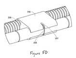
- FIG. 5Ais a perspective view of an insertion tool and a distractible intervertebral body fusion device according to an embodiment of the present invention.
- FIG. 5Bis a perspective view of an insertion tool and a distractible intervertebral body fusion device according to an embodiment of the present invention.
- FIG. 5Cis a perspective view of an insertion tool and a distractible intervertebral body fusion device according to an embodiment of the present invention.
- FIG. 5Dis a partial perspective view of an insertion tool according to an embodiment of the present invention.
- FIG. 6Ais an end view of a distractible intervertebral body fusion device according to an embodiment of the present invention.
- FIG. 6Bis a cross-sectional end view of the distractible intervertebral body fusion device of FIG. 6A taken looking into the page.
- FIG. 7Ais a front view of a distractible intervertebral body fusion device according to an embodiment of the present invention.
- FIG. 7Bis a cross-sectional view of the distractible intervertebral body fusion device of FIG. 7A taken along the lines 7 B- 7 B.
- FIG. 8Ais a front view of a distractible intervertebral body fusion device according to an embodiment of the present invention.
- FIG. 8Bis a cross-sectional view of the distractible intervertebral body fusion device of FIG. 8A taken along the lines 8 A- 8 A.
- FIG. 9Ais an exploded view of a distractible intervertebral body fusion device according to an embodiment of the present invention.
- FIG. 9Bis a perspective view of the distractible intervertebral body fusion device of FIG. 9A .
- FIG. 9Cis a front view of the distractible intervertebral body fusion device of FIG. 9A .
- FIG. 9Dis a cross-sectional view of the distractible intervertebral body fusion device of FIG. 9A taken along the lines 9 D- 9 D in FIG. 9C .
- FIG. 10Ais an exploded view of a distractible intervertebral body fusion device according to an embodiment of the present invention.
- FIG. 10Bis a perspective view of the distractible intervertebral body fusion device of FIG. 10A .
- FIG. 10Cis a bottom view of the distractible intervertebral body fusion device of FIG. 10A .
- FIG. 10Dis a cross-sectional view of the distractible intervertebral body fusion device of FIG. 10A taken along the lines 10 D- 10 D in FIG. 10C .
- FIG. 11Ais a perspective view of a distractible intervertebral body fusion device according to an embodiment of the present invention.
- FIG. 11Bis a front view of the distractible intervertebral body fusion device of FIG. 11A .
- FIG. 11Cis a cross-sectional view of the distractible intervertebral body fusion device of FIG. 11A taken along the lines 11 C- 11 C in FIG. 11B .
- FIG. 11Dis a cross-sectional view of the distractible intervertebral body fusion device of FIG. 11A taken along the lines 11 D- 11 D in FIG. 11B .
- FIG. 12Ais a perspective view of a distractible intervertebral body fusion device according to an embodiment of the present invention.
- FIG. 12Bis a side view of the distractible intervertebral body fusion device of FIG. 12A .
- FIG. 13Ais a perspective view of a distractible intervertebral body fusion device according to an embodiment of the present invention.
- FIG. 13Bis a side view of the distractible intervertebral body fusion device of FIG. 13A .
- FIG. 14Ais a perspective view of a distractible intervertebral body fusion device according to an embodiment of the present invention.
- FIG. 14Bis a side view of the distractible intervertebral body fusion device of FIG. 14A .
- FIG. 15is a perspective view of a pair of distractible intervertebral body fusion devices according to an embodiment of the present invention.
- FIG. 16Ais a top view of a distractible device according to an embodiment of the present invention in a compressed configuration.
- FIG. 16Bis a top view of the distractible device of FIG. 16A in an expanded configuration.
- FIG. 17Ais perspective view of a distractible device according to an embodiment of the present invention.
- FIG. 17Bis a partial cutaway view of the distractible device of FIG. 17A .
- FIG. 18Ais a perspective view of a distractible device according to an embodiment of the present invention.
- FIG. 18Bis a partial view of the distractible device according of FIG. 18A .
- FIG. 18Cis a partial view of the distractible device according of FIG. 18A .
- FIG. 18Dis a partial view of the distractible device according of FIG. 18A .
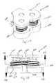
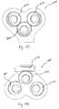
- FIGS. 1A-1Cthere can be seen a distractible intervertebral body fusion device 100 adapted for implantation into an intervertebral disc space of a patient according to an embodiment of the present invention.
- FIG. 1Ashows the device 100 in a fully compressed configuration
- FIG. 1Bshows the device 100 in a fully expanded configuration
- FIG. 1Cshows an exploded view of the device 100 .
- Device 100includes a first member 110 having a bearing surface 102 configured to interface with an end plate of one of a superior or an inferior vertebra of the intervertebral disc space and a second member 150 having a bearing surface 104 configured to interface with an end plate of the other of the superior or inferior vertebra.
- the bearing surfaces 102 , 104can include a textured surface, such as that provided by corrugations 114 , to create friction with the end plates of the vertebra to prevent accidental extrusion of the device 100 .
- the radii of the corrugation 114 valley and the corrugation 114 top widthcan be maximized to minimize the notch factor and reduce stress while still providing a corrugation design that reduces the propensity of the device 100 to extrude from the disc space.
- One or both of the members 110 , 150can also include an opening 173 , 153 extending through the member for facilitating bone growth through the device 100 .
- openingcan be filled with a gel, rubber, or other complaint material that can replicate the nucleus of an intervertebral disc and supplement the strength of the device in compressive, shear, and torsional loading conditions.
- a generally solid surface, a textured or etched surface, a scored or notched surface, or a surface with multiple openingscan be provided on each member 110 , 150 .
- Device 100can also include a pair of coaxial screw gear sleeve mechanisms including threaded post members 111 , 112 extending from first member 110 and a pair of threaded geared sleeves 120 , 130 configured to surround the post members 111 , 112 .
- Threaded post members 111 , 112can have threads 113 , 115 defined on an exterior surface thereof.
- Threaded geared sleeves 120 , 130can have both interior threads 122 , 132 configured to interface with the threads 113 , 115 of threaded post members 111 , 112 and exterior threads 121 , 131 .
- both the exterior 121 and interior 122 threads of one of the sleeves 120are of an opposite hand to the threads 131 , 132 of the other sleeve 130 .
- External threads 121 , 131 of sleeves 120 , 130can have gear teeth 124 , 134 cut into the thread.
- the gear teeth 124 , 134are not cut down to the root, or minor diameter, of the threads 121 , 131 in order to maximize the strength of the threads.
- threaded geared sleeves 120 , 130can fit within sleeve openings of 161 , 162 in second member 150 .
- Openings 161 , 162can include threaded portions 151 , 152 that mesh with exterior threads 121 , 131 of threaded geared sleeves 120 , 130 .
- sleeve openings 161 , 162extend all the way through bearing surface 104 of second member 150 .
- threaded geared sleeves 120 , 130can be substantially solid.
- threaded geared sleevescan include one or more slots through the sleeve for mass reduction and material savings or to promote bone in-growth.
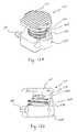
- the device 100can be expanded with the aid of a worm 140 that extends through a worm aperture 154 in the device 100 .
- the worm 140can have first 142 and second 141 opposing threaded sections configured to interface with the exterior threads having gear teeth 124 , 134 of threaded geared sleeves 120 , 130 through a pair of apertures 157 , 158 in threaded portions 151 , 152 of sleeve openings 161 , 162 .
- the worm 140can include a hex 143 , 144 at each end of the worm 140 that allows it to be driven by a delivery system (described below).
- Such a delivery systemcan also be attached to the device 100 when driving the worm 140 at tapped hole 156 A or tapped hole 156 B to stabilize the delivery system.
- Device 100can include a hex 143 , 144 and tapped hole 156 A, 156 B at each end of device, so that the device 100 can be inserted and driven from either end, or can include a hex and tapped hole at only one side of the device, limiting the device to insertion and distraction from a single direction.
- Bottom member 150can also include one or more scallops 155 above the worm aperture 154 that provide increased strength and thickness while still allowing the threaded geared sleeves 120 , 130 to rotate.
- a partial sectional view of a distractible intervertebral body fusion device 100 in FIG. 1Dhelps illustrate how the device can employ multiple coaxial screw gear sleeve mechanisms as telescoping mechanisms utilizing the threaded post members 111 , 112 , threaded geared sleeves 120 , 130 and the worm 140 to expand the first member 110 and second member 150 relative to each other.
- first threaded section 142 of worm 140pulls the gear teeth 134 of threaded geared sleeve 130 towards the hex head 144 . This causes the sleeve 130 to translate upward from the second member 150 along internal threads 152 .
- the threads for like components for each deviceare opposite handed, the threads 142 on one side of the worm 140 will be pulling the gear teeth 134 of the threaded geared sleeve 130 while the threads 141 on the other side of the worm 140 will be pushing the gear teeth 124 on the other sleeve 120 , or vice versa depending on the direction of rotation of the worm 140 .
- These opposing forces applied to the worm 140 by the threaded geared sleeves 120 , 130are carried in either tension or compression by the worm 140 . Therefore, the worm 140 is not substantially driven into or out of the worm aperture 154 as the device 100 is expanded or contracted. This is advantageous in that a pin or other retainer is not required to retain the worm and balance the forces in the device.
- Such a pincan be a point of excessive wear which can cause the life cycle of the device to be shorter lived.
- a pincan be employed to prevent the worm 140 from being able to be pulled or pushed axially, which can cause the device to become jammed.
- worm driveinclude piezoelectric actuators and any momentum imparting collision mechanism or configuration.
- a drive mechanismsuch as a worm
- the external threads of the threaded geared sleeveswould both be of the same hand and the worm would be screwed into the compressed device in the worm aperture.
- the axial position of the wormwould be constrained by the delivery system, instead of a pin, resulting in distraction of the device.
- the wormcould be screwed out of the worm aperture and the device could be locked in place by screwing in a threaded locking worm.
- the locking wormcould have an additional threaded or snapping feature that enables it to be permanently, or in a removable fashion, attached to the device.
- the locking wormcould be made from a radio transparent material such as PEEK, which would therefore allow imaging through the worm.
- the locking wormwould only need to be strong enough to inhibit the threaded geared sleeves from turning into or out of the device, and would not need to be strong enough to cause the device to distract.
- a larger radio transparent windowcould be formed by removing a portion of the sides of the bottom member on either side of the opening in the bottom member along the length of the device, so long as the device retained a necessary amount of stiffness.
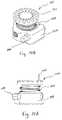
- FIGS. 2A and 2Ba preferred fit of gear teeth 124 , 134 of threaded geared sleeves 120 , 130 in internal threaded portions, 151 , 152 of second member 150 is shown.
- the gear teeth 124 , 134are thrust towards the internal threads 151 , 152 of the second member 150 by the worm, the load between the gear teeth 124 , 134 and threads 151 , 152 is balanced by the bearing surfaces 163 , 164 between the components, which results in the ability of the device 100 to distract a substantial load.
- This fit between the gear teeth 124 , 134 and the internal threads 151 , 152can be contrast with the fit shown in FIGS. 3A and 3B .
- threads depicted in the Figuresare all screw threads in the form of projecting helical ribs
- threadfor the purposes of the present invention can also refer to any other mechanism that translates rotational force into translational or longitudinal movement.
- threadscan be comprised of a recirculating or spiral arrangement of bearings or any other low friction arrangement, such as cooperating magnets.
- the height of the device 100 between the bearing surfaces 102 , 104 in the fully compressed configurationis 6.5 millimeters and the maximum fully distracted height is 12 millimeters, thus providing a very large amount of distraction relative to the initial height of the device.
- the maximum heightis defined by the largest height at which the device can meet the dynamic compressive, shear, and torsional requirements for implantable intervertebral body fusion devices. Variables that determine this height include the width of the threaded geared sleeves, which is limited by the desired width of the device, and the material from which the device is made. With regard to the material for the device, materials with higher fatigue performance allow the maximum height of the device to be taller even with a narrower width.
- the deviceis made from titanium.
- the devicemay also be made from cobalt chrome, MP35N, or PEEK, for increased strength characteristics or increased radiolucent characteristics, depending on the material.
- X-ray transparencyis a desirable property because it allows for the fusing bone to be imaged through the device.
- the devicecan be designed such that in the compressed configuration the threaded geared sleeves project through the bearing surface of second member in order to provide for an even greater amount of distraction.
- openings configured to contain the projecting portions of the sleevescan be cut into the adjacent vertebral end plate.
- device 100does not require a locking mechanism to maintain the desired height within the body. This is because, when driven backwards, the device exhibits a very high gear ratio which causes even the slightest friction in the system to overwhelm any amount of compression, torsion, or shear loading that might be applied to the device. In dynamic testing in shear, torsion, and compression, the maximum amount by which the height of the device changed was by approximately 0.01 millimeter. The device 100 , because height can be maintained at any point along the threaded geared sleeves, therefore also exhibits very high resolution height control, on the order of 1 micrometer.
- the external threads 121 , 131 and gear teeth 124 , 134 on the threaded geared sleeves 120 , 130can be substantially trapezoidal in shape.
- the threadis a trapezoidal 8 millimeter by 1.5 millimeter metric thread.
- a trapezoidal designenables a relatively large gear tooth size and, accordingly, a larger area over which the distraction loading is distributed.
- multiple gear teeth 124 , 134 on the threaded geared sleeves 120 , 130can be engaged by the worm 140 at the same time along the pressure angle ANG, as shown in FIGS. 4A and 4B . Distributing the distraction load over multiple teeth of the sleeves 120 , 130 and the worm 140 is critical to achieve the minimum device size while providing a maximum amount of distraction and load capacity.
- a delivery system 200 for implanting a distractible intervertebral body fusion device according to an embodiment of the present inventionis depicted in FIGS. 5A (compressed configuration), 5 B (partially distracted configuration, and 5 C (fully distracted configuration). Delivery system 200 also includes an actuation tool 300 for actuating the distraction.
- a hex 143 or 144 of deviceis first connected to the delivery system 200 via a socket driver on an end 201 of delivery shaft 203 .
- a threaded end 202 of delivery shaft 204can be threaded into one of tapped holes 156 A or 156 B in second member 150 of device 100 .
- the device 100can then be inserted into the body via a standard transforaminal lumbar interbody fusion (TLIF) or posterior lumbar interbody fusion (PLIF) procedure using the delivery system 200 .
- TLIFtransforaminal lumbar interbody fusion
- PLIFposterior lumbar interbody fusion
- a lateral interbody fusion through the lateral retroperitoneal corridoris another approach.
- the delivery system 200can guide the location of the device 100 as it is being inserted with use of handle 213 .
- Delivery system 200includes a hex 215 and a circumferential groove 214 at the near end of delivery shaft 204 , and also has a hex and circumferential groove (not pictured) at the end of delivery shaft 203 .
- the actuation tool 300can be connected to the delivery system by engaging an internal hex socket driver of the actuation tool with the hex on the end of the delivery shaft 203 , 204 .
- an internal snap ring or circumferential spring in actuation tool 300can engage the circumferential groove on delivery shaft 203 to ensure that the actuation tool 300 does not become accidentally disengaged during use.
- each mark 208can represent a distracted height of 1 millimeter.
- Delivery system 200can be configured so that when the device 100 reaches its maximum desired height, slider 206 abuts stop 205 so that it can be advanced no further, thus limiting the height of the device 100 .
- the device 100can limit its own expansion by welding two of the gear teeth 124 , 134 on one of the threaded geared sleeves 120 , 130 together so that they bind with the worm 140 when the device 100 has reached its maximum desired height.
- one or more of the gear teeth 124 , 134can be omitted or a small post can be inserted into the interstitial space between two gear teeth to limit the expansion of the device.
- a lever for applying torque to the shaft 204may be affixed to the hex 215 at the end of shaft 204 .
- the levermay be shaped and oriented such that when the device 100 is appropriately engaged with the delivery system 200 , the position of the lever allows access to the drive shaft 203 , whereas when the device is not appropriately engaged, the lever does not allow access to the drive shaft 203 .
- the slider 206may be contained with the handle 213 in order to reduce the length of the delivery system 200 .
- a tube able to carry loading in torsionmay be implemented around one of the shafts 203 , 204 to add to the structural rigidity of the delivery system.
- a small footmay be affixed to the tube to additionally support the ability of the delivery system to carry, and transmit, loading in torsion by and to the device.
- the shaft of the delivery system 200can be curved or bayonet in shape to allow visualization through a minimally invasive system and working channel.
- the actuation tool 300can include a recess or loop 304 that allows that user to spin the actuation tool 300 with a single finger and/or large gripping surfaces 301 that the user can grasp to turn the actuation tool 300 .
- the loopmay be lined with a slippery or bearing surface to enable the loop to spin easily around the user's gloved finger(s).
- the actuation tool 300can also include a broad surface 303 designed to receive the impact of a hammer for implantation. Recesses 302 can also be included on actuation tool 300 to afford the user an improved view of the device 100 while it is being implanted.
- Actuation tool 300can span both delivery shafts 203 , 204 and may extend over and/or receive handle 213 of delivery system 200 .
- the device 100can be driven by a powered actuation implement such as a pneumatic or electric drill or a motorized screwdriver mechanism, which, in some embodiments, can allow the tool to be controlled remotely.
- a powered actuation implementsuch as a pneumatic or electric drill or a motorized screwdriver mechanism, which, in some embodiments, can allow the tool to be controlled remotely.
- the actuation toolemploys sensors in the device to transmit data regarding the implantation parameters and environment, such as device load and muscular tension, to an operator or operating system to improve the performance of the surgical procedure and outcome.
- the delivery system 200could use small strain gauges located on the device 100 and/or load cells attached to the delivery shafts 203 , 204 and actuation tool to measure loads present during the implantation and distraction process. These gauges and/or load cells could be monitored by a microcontroller board located on the delivery system 200 and the information fed back to a monitoring computer via a standard interface such as a USB or wireless connection. This information could be used to closely monitor a procedure's progress, warn of impending problems and improve future procedures. If not fully bridged, the gauges could be configured as half bridges within the device and completed outside of the device. Standard signal conditioning amplifiers could be used to excite and condition the signal to yield a measurable output of voltage and current.
- the device 100can have a strengthened second member 150 as shown in FIGS. 6A and 6B .
- Thiscan be done by lowering the worm aperture 154 , and therefore the worm 140 , such that when the device 100 is expanded to its full height, the worm 140 engages a full gear tooth 134 A on the threaded geared sleeve 130 closest to the bottom 136 of the threaded geared sleeve 130 .
- Thisallows a top surface 166 of the second member 150 to be lowered, which allows the first member 110 to be thicker, and therefore stronger, while maintain the same initial height
- thisallows the material 168 between the top surface 166 of the second member 150 and the worm aperture 154 to be made thicker.
- a further advantage of this configurationis that at least one full internal thread 152 A of the second member 150 is in engagement with the threaded geared sleeve 134 when the device is fully distracted.
- an additional thickness 167can be added to the side of second member 150 opposite of the worm aperture 154 to what was previously described as the top surface 166 A of that side of the second member 150 . This allows for a full internal thread 152 B to engage the threaded geared sleeve 130 on the side opposite of internal thread 152 A.
- FIGS. 7A and 7Bdepict another embodiment of the present invention where in threaded posts 111 , 112 employ a buttress thread 113 A, 115 A (compare threads 113 A in FIG. 7B to threads 113 , 115 in FIG. 1D ).
- a buttress thread configurationresults in the load bearing thread face being perpendicular to the screw axis of the post 111 , 112 , which increases the axial strength of the device.
- FIGS. 8A and 8Bdepict a further embodiment that utilizes a standard 60 degree thread 113 B, 115 B on threaded posts 111 , 112 . 60 degree threads are considered industry standard and can therefore be created with common machining practices. This can result in a device that can be more quickly and inexpensively produced.
- FIGS. 9A-9Danother embodiment of a distractible intervertebral body fusion device 400 includes a single pair of threaded geared posts 423 extending between first member 410 and second member 450 rather than the separate threaded geared sleeves 120 , 130 and threaded posts 111 , 112 described previously.
- Threaded geared posts 423each include a threaded geared portion 421 and a post portion 411 .
- Threaded geared portions 421fit within openings 461 in second member 450 and interface with worm 440 and internal threads 451 to cause the device 400 to distract.
- Post portions 411fit within openings 416 in first member 410 and can be attached to washers 418 .
- Washers 418keep the first member 410 in place relative to the threaded geared posts 423 as the threaded geared posts 423 rotate freely independent of the first member 410 when the device 400 is actuated.
- the distraction between the first member 410 and the second member 450is caused by the thicker threaded geared portions 421 while the post portions 411 remain within the openings 416 in first member 410 . This leads to a device 400 having increased axial strength.
- FIGS. 10A-10Ddepict a further embodiment of a distractible intervertebral body fusion device 500 that allows for differential adjustment of the threaded geared sleeves 520 .
- Threaded posts 511can each include an arched portion 515 that corresponds to an arched recess 517 in first member 510 .
- the arched interface between the threaded posts 511 and the first member 510 created by the corresponding arched portions 515 and arched recesses 517allows the first member 510 to rotate and become angled relative to the second member 550 .
- a pin joint utilizing a pivot pin 572can be used to keep one interface between the first member 510 and a threaded post 511 stationary, while the other interface is allowed to slide due to the arched surfaces.
- Worm 540can be a two-part worm including a first portion 546 having a first threaded section 543 and second portion 548 having a second threaded section 544 that fits onto a post 547 of first portion 546 .
- the two portions 546 , 548can therefore be rotated independently of each other, with each driving a separate threaded geared sleeve 520 . Because each threaded geared sleeve 520 can be engaged separately, they can be distracted different amounts, resulting in an angled first member 510 as shown most clearly in FIG. 10D .
- Such a configurationaccommodates lordotic or kyphotic geometry.
- the arched recesses 517 in the first member 550 and arched surfaces 515 of the posts 511could be replaced with flexural joints or ball or cylinder and socket joints.
- FIGS. 11A-11DA distractible intervertebral body fusion device 600 according to another embodiment of the present invention is depicted in FIGS. 11A-11D .
- Device 600uses three coaxial screw gear sleeve mechanisms, each having a threaded geared sleeve 620 and a threaded post 621 , between first member 610 and second member 650 .
- the worm drive 640is rotated and it engages one of the threaded geared sleeves 620 , causing it to rotate.
- the first threaded geared sleeve 620rotates, it engages the other two threaded geared sleeves 620 , causing them to rotate and the device 600 to distract.
- the rotation of the threaded geared sleeves 620also causes the threaded posts 621 to distract, as described previously.
- Use of three coaxial screw gear sleeve mechanismsprovides for a device having increased strength in the axial direction, a broader surface area for supporting the endplate of the vertebral body, and a more shapely geometry.
- each of the three distraction mechanismscould be actuated independently to adjust the surface of the device in additional degrees of freedom.
- the drive mechanismsmay need to be flexible, in which case a bellows or spiral laser-cut drive mechanism capable of bending and transmitting torque could be implemented. More specifically, one such drive mechanism could wrap around many distraction mechanisms, and distract each one with only one input. In another embodiment, a flexible drive mechanism could be useful in actuating multiple drive mechanisms separately to control the members of the device in many spatial degrees.
- FIGS. 12A and 12Bdepict a distractible intervertebral body fusion device 700 that employs only a single coaxial screw gear mechanism having a threaded geared sleeve 720 and a threaded post 721 for distracting first member 710 relative to second member 750 with worm 740 .
- Device 700also can include first 774 and second 776 telescoping support elements. Telescoping support elements 774 , 776 serve to maintain the relative rotational positioning of the first member 710 with respect to the second member 750 , enabling the threaded geared sleeve 720 to rotate with respect to both the first member 710 and second member 750 to distract the device 700 .
- FIGS. 14A and 14Bdepict a further variation of device 700 that utilizes a plurality of spikes 778 extending from the first member 710 and second member 750 to rotationally constrain the first member 710 and second member 750 .
- the spikes 778contact the adjacent vertebral end plates and fix themselves to the end plates to prevent the first member 710 and second member 750 from rotating relative to each other.
- FIGS. 14A and 14Bdepicted in FIGS. 14A and 14B .
- This embodimentincludes only a threaded geared sleeve 720 between first member 710 and second member 750 and allows the first member 710 to rotate with the sleeve 720 as the device 700 is distracted via rotation of the worm 740 .
- first member 710could be rotationally free with respect to the threaded geared sleeve 720 so that the first member 710 is allowed to engage and not rotate against the endplate of the vertebral body.
- distractible intervertebral body fusion devices as described hereincan be made of titanium and the delivery system can be made primarily out of stainless steel.
- Components of each mechanism that slide against each othercan be made of different types of the general material.
- the first membercan be made from Ti 6Al 4V standard titanium, which has high smooth fatigue performance
- the threaded geared sleevescan be made from Ti 6Al 4V ELI, which has high notched fatigue performance.
- Such a combinationresults in each component being made out of a preferred material for its fatigue notch factor while the overall mechanism implements different materials where components are slidably arranged.
- deviceis shaped to be ergonomic.
- Devicecan have various shapes, such as, for example, rectangular, kidney, or football shaped.
- a kidney or football shaped devicemaximizes contact between the device and the vertebral bodies because the end plates of vertebrae tend to be slightly concave.
- One or both ends of the devicemay also be tapered in order to facilitate insertion. This minimizes the amount of force needed to initially insert the device and separate the vertebral bodies.
- the devicemay be convex along both its length and its width, or bi-convex. Device can be constructed in various sizes depending on the type of vertebra and size of patient with which it is being used.
- Devicecan be manufactured in various ways with, in some embodiments, different components of the device can be manufactured in different ways.
- thread millingcan be implemented to manufacture the various threads in device.
- Wire EDMcan be utilized to manufacture some or all of the holes and openings in the device. Assembly jigs and post processing steps can also be utilized to allow the device to be manufactured to exacting standards.
- a bone growth stimulantsuch as autograft, bone morphogenic protein, or bone enhancing material, may be delivered into device.
- bone growth stimulantis delivered through a hollow chamber in insertion tool before insertion tool is disengaged from device.
- the devicesupports in-vivo loads during the time fusion occurs between the vertebral bodies.
- the surface of the devicecan be treated to minimize surface roughness or to reduce pitting of the material within the body.
- a rough surface or pitscan increase the stress on the device, which can result in shortening of the fatigue life and/or reduce fatigue strength.
- the surfacecan be treated with electro-polishing, both removing burrs from the edges of the device and finishing the surface.
- the surfacecan be left untreated because a rough surface on the end plates helps prevent accidental extrusion of the device.
- the devicecan also be coated with a highly elastic, impermeable material to extend its fatigue life. Specifically, the impermeable material would prevent the corrosive properties of blood from degrading the device.
- the devicecan be comprised of a biocompatible material, so that no coating is necessary.
- the devicecan be made of a biodegradable material designed to degrade in the body at a selected stage of the healing process, such as after bone fusion.
- devices as described hereincan be used with various bone growth stimulants.
- a 3D premineralized silk fibroin protein scaffold carriercan be carried on the surface of or within the device to deliver a bone morphogenetic protein (BMP), which can optionally be combined with modified bone marrow stromal cells (bMSCs) to improve fusion.
- BMPbone morphogenetic protein
- bMSCsmodified bone marrow stromal cells
- a composite chitosan 3D fiber mesh scaffold or a gelatin scaffoldcan be used.
- the devicecan also utilize vascular endothelial growth factor (VEGF) by depositing immobilized VEGF on titanium alloy substrates coated with thin adherent polydopamine film to increase the attachment, viability and proliferation of human dermal cells to promote the development of blood supply to the fused bone through revascularization around the implant.
- VEGFvascular endothelial growth factor
- certain polymerssuch as biodegradable PLGA could be used to make a scaffold for VEGF to enhance neovascularization and bone regeneration.
- VEGFcan be used in conjunction with BMPs to inhibit the function of BMPs of promoting osteogenesis to allow the device to be continually adjusted over time.
- scaffolds on or around the devicecould be seeded with bone marrow derived stem cells, dental pulp derived stem cells and adipose derived stem cells.
- Scaffoldscan also be comprised of various materials including polyester (e.g., polylactic acid-co-glycolic acid or poly3-hydroxybuetyrate-co-3-hydorxyvalerate), silk (e.g., biomimetic, apatitie-coated porous biomaterial based on silk fibroin scaffolds), hydrogels such as polycaprolactone, polyepsilon-caprolactone/collagen (mPCL/Col) cospun with PEO or gelatin, mPCL/Col meshes with micron-sized fibers, and mPCL/Col microfibers cosprayed with Heprasil, and porous titanium and titanium alloys (such as a titanium-niobium-zirconium alloy) functionalized by a variety of surface treatments, such as a VEGF or calcium
- devicecan include structure adapted to retain bone within an interior of or adjacent to the implant.
- structurecan include a micro-level matrix or scaffolding or kerfs, divots, or other similar features in the body of device.
- Bonemay also be retained through use of a porous material such that bone is retained in the interstitial spaces of the material. Larger, extending features may also be implemented.
- Such featuressuch as a circumferential shroud, could also have the added function of stiffening the device in torsion.
- more than one distractible intervertebral body fusion devicecan be implanted into the disc space.
- a pair of devices 100can be implanted such that the outer surface 104 of the second member 150 of one of the devices 100 directly interfaces with the outer surface 102 of the first member 110 of the other device 100 .
- Such a configurationcan allow for use of a smaller access channel for implanting the devices.
- the cooperating surfaces 102 , 104 of the two devicesare flat.
- Devices 100can be actuated simultaneously or separately. Devices could also be flipped with respect to each other in order to have both drive mechanisms centrally located.
- the devicescould be configured to rotate or flex with respect to each other to allow for the bearing surfaces of the devices to adjust their position to comfortably engage with the endplates of the vertebral bodies, or to preserve motion of the spine.
- a rod and screwscan be used with the device as part of an assembly affixed to the vertebral body.
- posterior fixationwhereby rod(s) and screws are used to supplement the spine, may be used in combination with the device.
- the rod(s) and screwsmay be affixed to, or designed to engage, the implant.
- the members of the devicemay be extended and, effectively, folded over the sides of the adjacent vertebral bodies so that the device may be affixed to the vertebral bodies with screws placed through the extensions of the members of the device substantially parallel to the plane formed by the endplates of the vertebral bodies.
- an adhesivewhich may support osteogenesis, may be used to adhere the device to or within the spine.
- distractible intervertebral body fusion devicecan comprise an endplate enhanced with flexures to be capable of tilting front to back and/or side to side.
- coaxial screw gear sleeve mechanismsutilizing at least in part a flexible material can be oriented around the periphery of the device to allow for tilting in a variety of axes.
- a device capable of tiltingcan be beneficial in that providing additional degrees of flexibility built into the device can promote bone growth, distribute stress across the surface of the end plates, and allow the device to adjust to the curvature of an individual's spine.
- the devicecould be placed within a small sock-like slip made from, for example, silk, which could be filled with bone.
- a small sock-like slipmade from, for example, silk, which could be filled with bone.
- the sockwould prevent the bone from falling out of the implant and/or allow for more bone to be introduced into the implant from the space around the implant within the sock.
- Such a sockcould be closeable at one end and could attach to the delivery system during implantation of the device. The sock could be released from the delivery system during any of the later steps of implantation.
- a device in accordance with the various embodimentscan be used for a variety of intervertebral fusion applications, including, for example, cervical, thoracic anterior lumbar, trans-foraminal lumbar, extreme lateral lumbar, and posterior lumbar.
- Various embodiments of implantation procedures for these applicationsmay be as follows:
- CervicalThe device is implanted via an anterior approach at the C3 to C7 levels using autograft.
- the deviceis used with supplemental anterior plate fixation.
- Trans-foraminal lumbarThe device is implanted via a posterior approach from the L2 to S1 levels using autograft. The device is used with supplemental posterior rod fixation.
- Posterior lumbarThe device is implanted via a posterior approach from the L2 to S1 levels using autograft. Two devices are implanted; one on the left side of the disc space and the other on the right side of the disc space. The device is used with supplemental posterior rod fixation.
- Anterior lumbarThe device is implanted via an anterior approach from the L3 to S1 levels using autograft. The device is used with supplemental anterior plating fixation of posterior rod fixation.
- Extreme lateral lumbarThe device is implanted via a lateral approach from the T12 to L4 levels using autograft. The device is used with supplemental posterior rod fixation.
- the devicecan be used in vertebral body replacement. After resection of a vertebral body or multiple vertebrae due to fracture or tumor, the device can be distracted to bridge two separate vertebrae. The distracted device bridges and supports the void left after resection.
- the devicecan be constructed in different sizes to accommodate the size difference of cervical, thoracic and lumbar vertebrae.
- the devicecan be used as an interspinous distraction device as shown in FIGS. 16A and 16B .
- the device 800can be placed between two adjacent spinous processes 801 a , 801 b through a minimal access system.
- the devicecan be inserted in a collapsed configuration to allow ease of placement. Once in position, the device can be actuated to an expanded configuration with coaxial screw gear sleeve mechanisms 804 to lock the vertebrae in a distracted position.
- Coaxial screw gear sleeve mechanisms 804can be configured as described previously herein.
- the devicecan have gripping teeth 800 at the point of contact with the spinous processes 801 a , 801 b to help fix it in place.
- the devicecan be used for interspinous fusion.
- the devicecan be placed between two adjacent spinous processes through a minimal access system in a collapsed configuration. Once in position, the device can be actuated to lock the vertebra in a distracted position.
- the devicecan have a bolt locking mechanism or similar locking arrangement to lock the device in the distracted position and to lock the locking plates through the spinous processes.
- the devicecan also have gripping corrugations or features on the outside to help keep it in place. Autograft or bone fusion enhancing material can be placed in the open space in device.
- the devicecan be used as a distractible fracture reducing device for osteoporotic bone.
- the devicecan be inserted beneath an end plate fracture through a minimally invasive pedicle approach.
- the deviceis then actuated with a delivery system actuator. Once the fracture is reduced, the device is explanted and the void is filled with acrylic cement or another bone filler that will strengthen the bone.
- the devicecan be used in facet joint replacement. After resection of a hypertrophic facet joint, the device can be actuated. Each member can be fixed to adjacent vertebrae with a pedicle screw. This will allow motion similar to that of a facet joint and prevent instability.
- the devicecan be part of a soft fusion device system and can be used in combination with an intervertebral disc replacement device.
- the coaxial screw gear sleeve mechanism or threaded postmay also be used to make intervertebral disc replacement devices expandable.
- the devicecan be used as a programmable distraction cage with a dynameter and bone stimulator.
- a programmable micro-machine actuator devicecan be implanted within the device. The device is distracted during implantation and can provide force readings through a radio frequency communicator post-surgery. The shape of the device can be altered while it is implanted by distracting the members with the actuator device, which can result in lordosis, kyphosis, further distraction, or less distraction.
- a battery devicepowers the system and can also form a magnetic field that works as a bone stimulator. The battery life may be limited to a short period of time, such as one week.
- Small movements of the devicecan be used to generate electrical energy with piezo-electrics or conducting polymers that may be used to recharge the batteries, capacitors, or other such power storage devices.
- the devicemay be powered through an RF inductive or capacitatively coupled arrangement.
- the devicecan be a self-actuating distractible cage.
- the devicecan be inserted into the disc space in a collapsed state. Once the device is released, it can slowly distract to a preset height.
- the devicecan be used in facial maxillary surgery as a fracture lengthening device for mandibular fractures.
- the devicecan be designed with narrow members having perpendicular plates with holes that allow fixation of each member to either a proximal or distal fracture.
- the devicecan be actuated to a preset height. This will allow lengthening of the defect in cases of fracture bone loss, dysplasia, or hypoplasia.
- devicein orthopedic applications as a lengthening nail for distraction of long bone fractures. After an orthopedic fracture occurs with bone loss, a distractible elongating nail can be placed to lengthen the bone. The elongation occurs over a few days with micrometer movements. This application will involve a distraction device inserted in between the moving portion of the nails exerting counter-distraction forces, which will provide lengthening of the bone.
- the devicecan be used to replace phalangeal joints in the hand, metatarsal joints in the foot, or calcaneal-talus joints. These joints can have implants that will allow motion of adjacent bones and limit hyper-extension or hyper-flexion.
- FIGS. 17A and 17Bdepict a distractible device 900 including an enveloping coaxial screw gear sleeve with recirculating bearings according to another embodiment of the present invention.
- Device 900includes a post 910 , an enveloping coaxial screw gear sleeve 920 , a worm 930 and a housing 940 .
- Post 910includes a smooth outer surface 912 and a machined helical raceway 911 for bearings 913 .
- a helical raceway(not shown) is also machined into inner surface of enveloping coaxial screw gear sleeve 920 that is complementary to helical raceway 911 for accommodating bearings 913 .
- the inner surface of coaxial screw gear sleeve 920also includes a machined tunnel for recirculation of bearings 913 as the post 910 moves with respect to the sleeve 920 .
- the recirculating bearingsare depicted as bearings 914 in FIG. 17B .
- the outer surface of the enveloping coaxial screw gear sleevealso includes a helical raceway 921 for recirculating bearings 914 and an enveloping screw gear 922 .
- the worm 930has a helical thread configured to engage the enveloping screw gear 922 of the sleeve 920 .
- the inner surface of the housing 940has a helical raceway (not shown) that cooperates with helical raceway 921 to retain bearings 914 and a tunnel for recirculating bearings 914 as the coaxial screw gear sleeve 920 moves with respect to the housing 940 .
- the coaxial screw gear sleeve 920could have recirculating bearings both on the inside and the outside of the sleeve and the recirculation tunnel could be between the inside and the outside of the sleeve, facilitating assembly and manufacturing.
- the worm 930is rotated clockwise to engage the enveloping screw gear 922 to rotate and translate the enveloping coaxial screw gear sleeve 920 out of the housing 940 .
- Bearings 913 , 914enable the rotation of the enveloping coaxial screw gear sleeve 920 with very little friction, enabling the device 900 to exhibit a very high mechanical advantage and displacement control with very high resolution.
- the use of the enveloping screw gear 922enables the interface between the worm 930 and the enveloping coaxial screw gear sleeve 920 to carry substantially higher loading.
- Device 1000includes an enveloping coaxial screw gear 1010 , a housing 1020 and a worm 1030 .
- the outer surface of enveloping coaxial screw gear sleeve 1010includes a helical groove having a series of enveloping coaxial screw gear teeth 1014 .
- the helical groovecan cooperate with an internal thread 1021 on the inner surface 1022 of housing 1020 to allow the device 1000 to carry an axial load.
- the gear teeth 1014can be machined directly into the outer surface of the enveloping coaxial screw gear sleeve 1010 .
- the outer surface of the enveloping coaxial screw gear sleeve 1010can be a smooth machined surface that acts like a bearing surface when configured with a similar smooth bearing surface on the inner surface 1022 of housing 1020 to enable the device 1000 to carry a lateral load.
- the worm 1030is rotated to engage the enveloping coaxial screw gear teeth 1014 to rotate and translate the enveloping coaxial screw gear sleeve 1010 with respect to the housing 1020 .
- the inner surface 1010 and center bore 1012can be configured to contain a post similar to the post 910 described in FIGS. 17A and 17B to compound the distraction of the device.
- no thread 1021is present on the inner surface 1022 of housing 1020 , so the helical groove and/or gear teeth 1014 of the enveloping coxial screw gear sleeve 1010 cause the sleeve 1010 to translate with respect to the housing 1030 as the sleeve 1010 rotates.
- the worm 1030would carry any axial load, unassisted by an inclined interface between the enveloping coaxial screw gear sleeve 1010 and the housing 1020 .
Landscapes
- Health & Medical Sciences (AREA)
- Engineering & Computer Science (AREA)
- Orthopedic Medicine & Surgery (AREA)
- Biomedical Technology (AREA)
- Neurology (AREA)
- Life Sciences & Earth Sciences (AREA)
- Transplantation (AREA)
- Animal Behavior & Ethology (AREA)
- Heart & Thoracic Surgery (AREA)
- General Health & Medical Sciences (AREA)
- Public Health (AREA)
- Veterinary Medicine (AREA)
- Vascular Medicine (AREA)
- Cardiology (AREA)
- Oral & Maxillofacial Surgery (AREA)
- General Engineering & Computer Science (AREA)
- Surgery (AREA)
- Mechanical Engineering (AREA)
- Physical Education & Sports Medicine (AREA)
- Molecular Biology (AREA)
- Medical Informatics (AREA)
- Nuclear Medicine, Radiotherapy & Molecular Imaging (AREA)
- Prostheses (AREA)
- Surgical Instruments (AREA)
- Transmission Devices (AREA)
- Gear Transmission (AREA)
Abstract
Description
Claims (46)
Priority Applications (7)
| Application Number | Priority Date | Filing Date | Title |
|---|---|---|---|
| US12/841,465US8303663B2 (en) | 2009-07-22 | 2010-07-22 | Methods and apparatuses for vertebral body distraction and fusion employing a coaxial screw gear sleeve mechanism |
| US13/189,410US8636746B2 (en) | 2009-12-31 | 2011-07-22 | Methods and apparatus for insertion of vertebral body distraction and fusion devices |
| US13/591,463US8771360B2 (en) | 2009-07-22 | 2012-08-22 | Methods and apparatuses for vertebral body distraction and fusion employing a coaxial screw gear sleeve mechanism |
| US14/318,196US9474626B2 (en) | 2009-07-22 | 2014-06-27 | Methods and apparatuses for vertebral body distraction and fusion employing a coaxial screw gear sleeve mechanism |
| US15/332,066US10369008B2 (en) | 2009-07-22 | 2016-10-24 | Medical device employing a coaxial screw gear sleeve mechanism |
| US16/529,897US11612496B2 (en) | 2009-07-22 | 2019-08-02 | Medical device employing a coaxial screw gear sleeve mechanism |
| US18/124,908US20230320868A1 (en) | 2009-07-22 | 2023-03-22 | Medical Device Employing a Coaxial Screw Gear Sleeve Mechanism |
Applications Claiming Priority (3)
| Application Number | Priority Date | Filing Date | Title |
|---|---|---|---|
| US27154809P | 2009-07-22 | 2009-07-22 | |
| US36513110P | 2010-07-16 | 2010-07-16 | |
| US12/841,465US8303663B2 (en) | 2009-07-22 | 2010-07-22 | Methods and apparatuses for vertebral body distraction and fusion employing a coaxial screw gear sleeve mechanism |
Related Child Applications (2)
| Application Number | Title | Priority Date | Filing Date |
|---|---|---|---|
| US12/650,994Continuation-In-PartUS8523944B2 (en) | 2008-12-31 | 2009-12-31 | Methods and apparatus for vertebral body distraction and fusion employing flexure members |
| US13/591,463ContinuationUS8771360B2 (en) | 2009-07-22 | 2012-08-22 | Methods and apparatuses for vertebral body distraction and fusion employing a coaxial screw gear sleeve mechanism |
Publications (2)
| Publication Number | Publication Date |
|---|---|
| US20110160861A1 US20110160861A1 (en) | 2011-06-30 |
| US8303663B2true US8303663B2 (en) | 2012-11-06 |
Family
ID=43499660
Family Applications (9)
| Application Number | Title | Priority Date | Filing Date |
|---|---|---|---|
| US12/841,869Active2033-12-30US9358125B2 (en) | 2009-07-22 | 2010-07-22 | Coaxial screw gear sleeve mechanism |
| US12/841,465ActiveUS8303663B2 (en) | 2009-07-22 | 2010-07-22 | Methods and apparatuses for vertebral body distraction and fusion employing a coaxial screw gear sleeve mechanism |
| US13/591,463ActiveUS8771360B2 (en) | 2009-07-22 | 2012-08-22 | Methods and apparatuses for vertebral body distraction and fusion employing a coaxial screw gear sleeve mechanism |
| US14/318,196ActiveUS9474626B2 (en) | 2009-07-22 | 2014-06-27 | Methods and apparatuses for vertebral body distraction and fusion employing a coaxial screw gear sleeve mechanism |
| US15/174,454Active2030-11-02US10117757B2 (en) | 2009-07-22 | 2016-06-06 | Coaxial screw gear sleeve mechanism |
| US15/332,066ActiveUS10369008B2 (en) | 2009-07-22 | 2016-10-24 | Medical device employing a coaxial screw gear sleeve mechanism |
| US16/180,448Active2031-04-26US11026804B2 (en) | 2009-07-22 | 2018-11-05 | Coaxial screw gear sleeve mechanism |
| US16/529,897Active2032-04-18US11612496B2 (en) | 2009-07-22 | 2019-08-02 | Medical device employing a coaxial screw gear sleeve mechanism |
| US18/124,908PendingUS20230320868A1 (en) | 2009-07-22 | 2023-03-22 | Medical Device Employing a Coaxial Screw Gear Sleeve Mechanism |
Family Applications Before (1)
| Application Number | Title | Priority Date | Filing Date |
|---|---|---|---|
| US12/841,869Active2033-12-30US9358125B2 (en) | 2009-07-22 | 2010-07-22 | Coaxial screw gear sleeve mechanism |
Family Applications After (7)
| Application Number | Title | Priority Date | Filing Date |
|---|---|---|---|
| US13/591,463ActiveUS8771360B2 (en) | 2009-07-22 | 2012-08-22 | Methods and apparatuses for vertebral body distraction and fusion employing a coaxial screw gear sleeve mechanism |
| US14/318,196ActiveUS9474626B2 (en) | 2009-07-22 | 2014-06-27 | Methods and apparatuses for vertebral body distraction and fusion employing a coaxial screw gear sleeve mechanism |
| US15/174,454Active2030-11-02US10117757B2 (en) | 2009-07-22 | 2016-06-06 | Coaxial screw gear sleeve mechanism |
| US15/332,066ActiveUS10369008B2 (en) | 2009-07-22 | 2016-10-24 | Medical device employing a coaxial screw gear sleeve mechanism |
| US16/180,448Active2031-04-26US11026804B2 (en) | 2009-07-22 | 2018-11-05 | Coaxial screw gear sleeve mechanism |
| US16/529,897Active2032-04-18US11612496B2 (en) | 2009-07-22 | 2019-08-02 | Medical device employing a coaxial screw gear sleeve mechanism |
| US18/124,908PendingUS20230320868A1 (en) | 2009-07-22 | 2023-03-22 | Medical Device Employing a Coaxial Screw Gear Sleeve Mechanism |
Country Status (9)
| Country | Link |
|---|---|
| US (9) | US9358125B2 (en) |
| EP (2) | EP2456396B1 (en) |
| JP (1) | JP5656997B2 (en) |
| CN (1) | CN102625682B (en) |
| CA (1) | CA2768867C (en) |
| DK (1) | DK2456396T3 (en) |
| ES (2) | ES2653567T3 (en) |
| IN (1) | IN2012DN00952A (en) |
| WO (2) | WO2011011626A2 (en) |
Cited By (210)
| Publication number | Priority date | Publication date | Assignee | Title |
|---|---|---|---|---|
| US20110178599A1 (en)* | 2009-09-17 | 2011-07-21 | Brett Darrell C | Intervertebral implant having extendable bone fixation members |
| US20110230971A1 (en)* | 2009-04-15 | 2011-09-22 | Synthes Usa, Llc | Arcuate fixation member |
| US20120197404A1 (en)* | 2011-02-02 | 2012-08-02 | Philipp Brun | Intervertebral implant having extendable bone fixation members |
| US20120197403A1 (en)* | 2011-01-27 | 2012-08-02 | Warsaw Orthopedic. Inc. | Expandable medical implant |
| US20120232660A1 (en)* | 2010-04-12 | 2012-09-13 | Daniel Davenport | Expandable Trial Assembly For Expandable Vertebral Implant |
| US20120310350A1 (en)* | 2011-06-03 | 2012-12-06 | Biospine, Llc | Unidirectional dynamic interbody fusion device and method of use |
| US20130138112A1 (en)* | 2010-04-14 | 2013-05-30 | Depuy (Ireland) | Distractor |
| US20130253650A1 (en)* | 2008-12-10 | 2013-09-26 | Coalign Innovations, Inc. | Adjustable Distraction Cage With Linked Locking Mechanisms |
| US8771360B2 (en) | 2009-07-22 | 2014-07-08 | Spinex Tec, Llc | Methods and apparatuses for vertebral body distraction and fusion employing a coaxial screw gear sleeve mechanism |
| WO2014116891A1 (en)* | 2013-01-24 | 2014-07-31 | Biospine, Llc | Adjustable interbody fusion device and method of use |
| US20140288652A1 (en)* | 2013-03-12 | 2014-09-25 | Heinrich Boehm | Expandable implant for the spinal column |
| US8894710B2 (en) | 2008-12-10 | 2014-11-25 | Coalign Innovations, Inc. | Lockable spinal implant |
| US8900312B2 (en)* | 2013-03-12 | 2014-12-02 | Spine Wave, Inc. | Expandable interbody fusion device with graft chambers |
| US8906100B2 (en) | 2008-12-31 | 2014-12-09 | Ex Technology, Llc | Methods and apparatus for vertebral body distraction and fusion employing flexure members |
| US8932302B2 (en) | 2011-07-22 | 2015-01-13 | Spinex Tec, Llc | Methods and apparatus for insertion of vertebral body distraction and fusion devices |
| US8932355B2 (en) | 2008-02-22 | 2015-01-13 | Coalign Innovations, Inc. | Spinal implant with expandable fixation |
| EP2826446A1 (en) | 2013-07-19 | 2015-01-21 | Böhm, Heinrich, Dr. | Expandable implant for the spinal column |
| US8940049B1 (en) | 2014-04-01 | 2015-01-27 | Ex Technology, Llc | Expandable intervertebral cage |
| US9078767B1 (en) | 2014-03-06 | 2015-07-14 | Spine Wave, Inc. | Expandable spinal interbody fusion device |
| US20150335446A9 (en)* | 2010-01-12 | 2015-11-26 | Globus Medical, Inc | Expandable Spacer and Method of Use Thereof |
| US9216096B2 (en) | 2010-03-16 | 2015-12-22 | Pinnacle Spine Group, Llc | Intervertebral implants and related tools |
| US9265623B2 (en) | 2014-03-06 | 2016-02-23 | Spine Wave, Inc. | Method of expanding a spinal interbody fusion device |
| US9295562B2 (en) | 2008-01-17 | 2016-03-29 | DePuy Synthes Products, Inc. | Expandable intervertebral implant and associated method of manufacturing the same |
| US20160089247A1 (en)* | 2013-05-13 | 2016-03-31 | Biomet Spine, Llc | Adjustable interbody fusion devices |
| US9320610B2 (en) | 2011-08-16 | 2016-04-26 | Stryker European Holdings I, Llc | Expandable implant |
| US9320615B2 (en) | 2010-06-29 | 2016-04-26 | DePuy Synthes Products, Inc. | Distractible intervertebral implant |
| US9380932B1 (en) | 2011-11-02 | 2016-07-05 | Pinnacle Spine Group, Llc | Retractor devices for minimally invasive access to the spine |
| US9393130B2 (en) | 2013-05-20 | 2016-07-19 | K2M, Inc. | Adjustable implant and insertion tool |
| US9402737B2 (en) | 2007-06-26 | 2016-08-02 | DePuy Synthes Products, Inc. | Highly lordosed fusion cage |
| US9408715B2 (en) | 2009-04-15 | 2016-08-09 | DePuy Synthes Products, Inc. | Arcuate fixation member |
| US9414934B2 (en) | 2008-04-05 | 2016-08-16 | DePuy Synthes Products, Inc. | Expandable intervertebral implant |
| US9439783B2 (en) | 2014-03-06 | 2016-09-13 | Spine Wave, Inc. | Inserter for expanding body tissue |
| US9445921B2 (en) | 2014-03-06 | 2016-09-20 | Spine Wave, Inc. | Device for expanding and supporting body tissue |
| US9486328B2 (en) | 2014-04-01 | 2016-11-08 | Ex Technology, Llc | Expandable intervertebral cage |
| US9526620B2 (en) | 2009-03-30 | 2016-12-27 | DePuy Synthes Products, Inc. | Zero profile spinal fusion cage |
| US9561117B2 (en) | 2012-07-26 | 2017-02-07 | DePuy Synthes Products, Inc. | Expandable implant |
| US9597194B2 (en) | 2005-09-23 | 2017-03-21 | Ldr Medical | Intervertebral disc prosthesis |
| US9713535B2 (en) | 2006-02-15 | 2017-07-25 | Ldr Medical | Transforaminal intersomatic cage for an intervertebral fusion graft and an instrument for implanting the cage |
| US9717601B2 (en) | 2013-02-28 | 2017-08-01 | DePuy Synthes Products, Inc. | Expandable intervertebral implant, system, kit and method |
| US9724207B2 (en) | 2003-02-14 | 2017-08-08 | DePuy Synthes Products, Inc. | In-situ formed intervertebral fusion device and method |
| US9750619B2 (en) | 2011-09-07 | 2017-09-05 | Depuy Ireland Unlimited Company | Surgical instrument |
| US9750552B2 (en) | 2009-07-06 | 2017-09-05 | DePuy Synthes Products, Inc. | Expandable fixation assemblies |
| US9750618B1 (en) | 2016-11-29 | 2017-09-05 | Amendia, Inc. | Intervertebral implant device with independent distal-proximal expansion |
| US9782271B2 (en) | 2008-02-28 | 2017-10-10 | Stryker European Holdings I, Llc | Expandable intervertebral implant |
| US9795485B2 (en) | 2007-06-08 | 2017-10-24 | Ldr Medical | Intersomatic cage, intervertebral prosthesis, anchoring device and implantation instruments |
| US9833334B2 (en) | 2010-06-24 | 2017-12-05 | DePuy Synthes Products, Inc. | Enhanced cage insertion assembly |
| US9833331B2 (en) | 2009-12-31 | 2017-12-05 | Ldr Medical | Anchoring device and system for an intervertebral implant, intervertebral implant and implantation instrument |
| US9867717B2 (en) | 2009-03-19 | 2018-01-16 | Ex Technology, Llc | Stable device for intervertebral distraction and fusion |
| US9889019B2 (en) | 2013-08-29 | 2018-02-13 | Spineex, Inc. | Expandable and adjustable lordosis interbody fusion system |
| US9913727B2 (en) | 2015-07-02 | 2018-03-13 | Medos International Sarl | Expandable implant |
| US9937050B2 (en) | 2013-05-16 | 2018-04-10 | Ldr Medical | Vertebral implant, vertebral fastening device of the implant and implant instrumentation |
| US9949769B2 (en) | 2004-03-06 | 2018-04-24 | DePuy Synthes Products, Inc. | Dynamized interspinal implant |
| US20180110628A1 (en)* | 2016-10-26 | 2018-04-26 | Howmedica Osteonics Corp. | Expandable interbody implant with lateral articulation |
| US9974662B2 (en) | 2016-06-29 | 2018-05-22 | Globus Medical, Inc. | Expandable fusion device and method of installation thereof |
| US9993349B2 (en) | 2002-06-27 | 2018-06-12 | DePuy Synthes Products, Inc. | Intervertebral disc |
| US10052215B2 (en) | 2016-06-29 | 2018-08-21 | Globus Medical, Inc. | Expandable fusion device and method of installation thereof |
| US10070970B2 (en) | 2013-03-14 | 2018-09-11 | Pinnacle Spine Group, Llc | Interbody implants and graft delivery systems |
| US10154911B2 (en) | 2013-03-13 | 2018-12-18 | Life Spine, Inc. | Expandable implant assembly |
| US10159582B2 (en) | 2011-09-16 | 2018-12-25 | DePuy Synthes Products, Inc. | Removable, bone-securing cover plate for intervertebral fusion cage |
| US10172718B2 (en)* | 2005-03-31 | 2019-01-08 | Life Spine, Inc. | Expandable interbody and intravertebral body devices |
| US10182922B2 (en) | 2011-12-14 | 2019-01-22 | Biospine, Llc | Unilateral moveable interbody fusion device and method of use |
| US10219914B2 (en) | 2015-11-10 | 2019-03-05 | Globus Medical, Inc. | Stabilized expandable intervertebral spacer |
| US10314718B2 (en) | 2016-09-22 | 2019-06-11 | Loubert S. Suddaby | Expandable intervertebral fusion implant |
| US20190201210A1 (en)* | 2017-12-18 | 2019-07-04 | Nuvasive, Inc. | Expandable implant device |
| US10342675B2 (en) | 2013-03-11 | 2019-07-09 | Stryker European Holdings I, Llc | Expandable implant |
| WO2019140240A1 (en) | 2018-01-11 | 2019-07-18 | K2M, Inc. | Implants and instruments with flexible features |
| US10369015B2 (en) | 2010-09-23 | 2019-08-06 | DePuy Synthes Products, Inc. | Implant inserter having a laterally-extending dovetail engagement feature |
| US10383741B2 (en) | 2013-03-13 | 2019-08-20 | Life Spine, Inc. | Expandable spinal interbody assembly |
| US10390963B2 (en) | 2006-12-07 | 2019-08-27 | DePuy Synthes Products, Inc. | Intervertebral implant |
| US10398563B2 (en) | 2017-05-08 | 2019-09-03 | Medos International Sarl | Expandable cage |
| US10426632B2 (en) | 2013-03-13 | 2019-10-01 | Life Spine, Inc. | Expandable spinal interbody assembly |
| US10433974B2 (en) | 2003-06-30 | 2019-10-08 | DePuy Synthes Products, Inc. | Intervertebral implant with conformable endplate |
| US10470891B2 (en) | 2016-09-12 | 2019-11-12 | Howmedica Osteonics Corp. | Interbody implant with independent control of expansion at multiple locations |
| US10478310B2 (en) | 2014-05-06 | 2019-11-19 | Ldr Medical, S.A.S. | Vertebral implant, device for vertebral attachment of the implant and instrumentation for implantation thereof |
| US10500062B2 (en) | 2009-12-10 | 2019-12-10 | DePuy Synthes Products, Inc. | Bellows-like expandable interbody fusion cage |
| US10537436B2 (en) | 2016-11-01 | 2020-01-21 | DePuy Synthes Products, Inc. | Curved expandable cage |
| US10548743B2 (en) | 2014-12-16 | 2020-02-04 | Globus Medical, Inc. | Expandable fusion devices and methods of installation thereof |
| US10548738B2 (en) | 2016-04-07 | 2020-02-04 | Howmedica Osteonics Corp. | Expandable interbody implant |
| US10596010B2 (en) | 2017-09-18 | 2020-03-24 | Loubert S. Suddaby | Stand-alone expandable interbody spinal fusion device with locking mechanism |
| US10864086B2 (en) | 2010-02-24 | 2020-12-15 | Globus Medical, Inc. | Expandable intervertebral spacer and method of posterior insertion thereof |
| US10888433B2 (en) | 2016-12-14 | 2021-01-12 | DePuy Synthes Products, Inc. | Intervertebral implant inserter and related methods |
| US10940018B2 (en) | 2016-05-20 | 2021-03-09 | Howmedica Osteonics Corp. | Expandable interbody implant with lordosis correction |
| US10940016B2 (en) | 2017-07-05 | 2021-03-09 | Medos International Sarl | Expandable intervertebral fusion cage |
| US11033403B2 (en) | 2017-07-10 | 2021-06-15 | Life Spine, Inc. | Expandable implant assembly |
| US11065132B2 (en) | 2014-03-06 | 2021-07-20 | Spine Wave, Inc. | Method of expanding a space between opposing tissue surfaces |
| USRE48719E1 (en) | 2014-10-09 | 2021-09-07 | K2M, Inc. | Expandable spinal interbody spacer and method of use |
| WO2021207364A1 (en) | 2020-04-07 | 2021-10-14 | K2M, Inc. | Expandable implant with worm gear |
| US11191650B2 (en) | 2020-02-03 | 2021-12-07 | Globus Medical Inc. | Expandable fusions devices, instruments, and methods thereof |
| US11207192B2 (en) | 2017-01-26 | 2021-12-28 | Loubert S. Suddaby | Stand-alone expandable interbody spinal fusion device with integrated fixation mechanism |
| US11219532B2 (en) | 2017-09-18 | 2022-01-11 | Loubert S. Suddaby | Stand-alone expandable interbody spinal fusion device with locking mechanism |
| US11234835B2 (en) | 2019-03-05 | 2022-02-01 | Octagon Spine Llc | Transversely expandable minimally invasive intervertebral cage |
| US11285014B1 (en) | 2020-11-05 | 2022-03-29 | Warsaw Orthopedic, Inc. | Expandable inter-body device, system, and method |
| US11291554B1 (en) | 2021-05-03 | 2022-04-05 | Medtronic, Inc. | Unibody dual expanding interbody implant |
| US11298240B2 (en) | 2020-06-16 | 2022-04-12 | Globus Medical, Inc. | Expanding intervertebral implants |
| US11304818B2 (en) | 2013-03-13 | 2022-04-19 | Life Spine, Inc. | Expandable spinal interbody assembly |
| US11337829B2 (en) | 2018-03-09 | 2022-05-24 | K2M, Inc. | Devices for inserting and expanding spinal implants |
| US11344424B2 (en) | 2017-06-14 | 2022-05-31 | Medos International Sarl | Expandable intervertebral implant and related methods |
| US11357640B2 (en) | 2020-07-08 | 2022-06-14 | Globus Medical Inc. | Expandable interbody fusions devices |
| US11376134B1 (en) | 2020-11-05 | 2022-07-05 | Warsaw Orthopedic, Inc. | Dual expanding spinal implant, system, and method of use |
| US11382764B2 (en) | 2019-06-10 | 2022-07-12 | Life Spine, Inc. | Expandable implant assembly with compression features |
| US11395743B1 (en) | 2021-05-04 | 2022-07-26 | Warsaw Orthopedic, Inc. | Externally driven expandable interbody and related methods |
| US11426290B2 (en) | 2015-03-06 | 2022-08-30 | DePuy Synthes Products, Inc. | Expandable intervertebral implant, system, kit and method |
| US11426286B2 (en) | 2020-03-06 | 2022-08-30 | Eit Emerging Implant Technologies Gmbh | Expandable intervertebral implant |
| US11446156B2 (en) | 2018-10-25 | 2022-09-20 | Medos International Sarl | Expandable intervertebral implant, inserter instrument, and related methods |
| US11446161B2 (en) | 2019-08-15 | 2022-09-20 | Adcura, Inc. | Translating dual axis adjustable interbody fusion spinal system |
| US11452607B2 (en) | 2010-10-11 | 2022-09-27 | DePuy Synthes Products, Inc. | Expandable interspinous process spacer implant |
| US11452614B2 (en) | 2013-08-29 | 2022-09-27 | Adcura, Inc. | Expandable and adjustable lordosis interbody fusion system |
| US11491020B2 (en) | 2020-07-09 | 2022-11-08 | Globus Medical, Inc. | Articulating and expandable interbody fusions devices |
| US11491028B2 (en) | 2016-02-26 | 2022-11-08 | K2M, Inc. | Insertion instrument for expandable spinal implants |
| US11497622B2 (en) | 2019-03-05 | 2022-11-15 | Ex Technology, Llc | Transversely expandable minimally invasive intervertebral cage and insertion and extraction device |
| US11497619B2 (en) | 2013-03-07 | 2022-11-15 | DePuy Synthes Products, Inc. | Intervertebral implant |
| US11510788B2 (en) | 2016-06-28 | 2022-11-29 | Eit Emerging Implant Technologies Gmbh | Expandable, angularly adjustable intervertebral cages |
| US11517443B2 (en) | 2020-11-05 | 2022-12-06 | Warsaw Orthopedic, Inc. | Dual wedge expandable implant, system and method of use |
| US11554020B2 (en) | 2020-09-08 | 2023-01-17 | Life Spine, Inc. | Expandable implant with pivoting control assembly |
| US11564724B2 (en) | 2020-11-05 | 2023-01-31 | Warsaw Orthopedic, Inc. | Expandable inter-body device, system and method |
| US11596522B2 (en) | 2016-06-28 | 2023-03-07 | Eit Emerging Implant Technologies Gmbh | Expandable and angularly adjustable intervertebral cages with articulating joint |
| US11602439B2 (en) | 2020-04-16 | 2023-03-14 | Life Spine, Inc. | Expandable implant assembly |
| US11602440B2 (en) | 2020-06-25 | 2023-03-14 | Life Spine, Inc. | Expandable implant assembly |
| US11612499B2 (en) | 2021-06-24 | 2023-03-28 | Warsaw Orthopedic, Inc. | Expandable interbody implant |
| US11622864B2 (en) | 2019-06-28 | 2023-04-11 | Innovasis, Inc. | Expandable intervertebral implant |
| US11628068B2 (en) | 2013-03-15 | 2023-04-18 | Globus Medical, Inc. | Expandable intervertebral implant |
| US11638653B2 (en) | 2020-11-05 | 2023-05-02 | Warsaw Orthopedic, Inc. | Surgery instruments with a movable handle |
| US11648132B2 (en) | 2019-09-24 | 2023-05-16 | Adcura, Inc | Surgical instrument for operating spinal implant system with dual axis adjustability and method of operating same |
| US11660205B2 (en) | 2019-08-15 | 2023-05-30 | Adcura, Inc. | Dual-axis adjustable spinal systems and interbody fusion devices with fixation |
| US11666457B2 (en) | 2009-10-15 | 2023-06-06 | Globus Medical Inc. | Expandable fusion device and method of installation thereof |
| US11678894B2 (en) | 2017-12-15 | 2023-06-20 | Jonathan P. Cabot | Knee balancing instrument |
| US11690733B2 (en) | 2009-10-15 | 2023-07-04 | Globus Medical Inc. | Expandable fusion device and method of installation thereof |
| US11701236B2 (en) | 2013-03-01 | 2023-07-18 | Globus Medical, Inc. | Articulating expandable intervertebral implant |
| US11701239B2 (en) | 2017-01-26 | 2023-07-18 | Loubert S. Suddaby | Stand-alone expandable interbody spinal fusion device with integrated fixation mechanism |
| US11717420B2 (en) | 2011-09-30 | 2023-08-08 | Globus Medical, Inc. | Expandable fusion device and method of installation thereof |
| US11723780B2 (en) | 2015-07-17 | 2023-08-15 | Globus Medical, Inc. | Intervertebral spacer and plate |
| US11730608B2 (en) | 2021-07-13 | 2023-08-22 | Warsaw Orthopedic, Inc. | Monoblock expandable interbody implant |
| US11744714B2 (en) | 2015-05-21 | 2023-09-05 | Globus Medical Inc. | Device and method for deployment of an anchoring device for intervertebral spinal fusion |
| US11752009B2 (en) | 2021-04-06 | 2023-09-12 | Medos International Sarl | Expandable intervertebral fusion cage |
| US11759328B2 (en) | 2019-09-06 | 2023-09-19 | Globus Medical Inc. | Expandable motion preservation spacer |
| US11766340B2 (en) | 2013-03-01 | 2023-09-26 | Globus Medical, Inc. | Articulating expandable intervertebral implant |
| US11771564B2 (en) | 2013-02-15 | 2023-10-03 | Globus Medical Inc. | Articulating and expandable vertebral implant |
| US11793653B2 (en) | 2012-04-16 | 2023-10-24 | Biospine, Llc | Multiple spindle adjustable interbody fusion devices and methods of use |
| US11801148B2 (en) | 2010-06-25 | 2023-10-31 | Globus Medical, Inc. | Expandable fusion device and method of installation thereof |
| US11806250B2 (en) | 2018-02-22 | 2023-11-07 | Warsaw Orthopedic, Inc. | Expandable spinal implant system and method of using same |
| US11813175B2 (en) | 2012-12-31 | 2023-11-14 | Globus Medical, Inc. | Spinous process fixation system and methods thereof |
| US11826263B2 (en) | 2010-09-03 | 2023-11-28 | Globus Medical, Inc. | Expandable fusion device and method of installation thereof |
| US11833059B2 (en) | 2020-11-05 | 2023-12-05 | Warsaw Orthopedic, Inc. | Expandable inter-body device, expandable plate system, and associated methods |
| US11844703B2 (en) | 2010-06-25 | 2023-12-19 | Globus Medical Inc. | Expandable fusion device and method of installation thereof |
| US11850163B2 (en) | 2022-02-01 | 2023-12-26 | Warsaw Orthopedic, Inc. | Interbody implant with adjusting shims |
| US11850160B2 (en) | 2021-03-26 | 2023-12-26 | Medos International Sarl | Expandable lordotic intervertebral fusion cage |
| US11857432B2 (en) | 2020-04-13 | 2024-01-02 | Life Spine, Inc. | Expandable implant assembly |
| US11857437B2 (en) | 2010-09-03 | 2024-01-02 | Globus Medical, Inc. | Expandable fusion device and method of installation thereof |
| US11883080B1 (en) | 2022-07-13 | 2024-01-30 | Globus Medical, Inc | Reverse dynamization implants |
| US11890203B2 (en) | 2009-10-15 | 2024-02-06 | Globus Medical, Inc | Expandable fusion device and method of installation thereof |
| US11896493B2 (en) | 2015-12-16 | 2024-02-13 | Globus Medical, Inc | Expandable intervertebral spacer |
| US11896499B2 (en) | 2021-12-02 | 2024-02-13 | Globus Medical, Inc | Expandable fusion device with integrated deployable retention spikes |
| US11896492B2 (en) | 2013-03-15 | 2024-02-13 | Globus Medical, Inc. | Expandable intervertebral implant |
| US11896496B2 (en) | 2015-05-21 | 2024-02-13 | Globus Medical, Inc. | Device and method for deployment of an anchoring device for intervertebral spinal fusion |
| US11896494B2 (en) | 2017-07-10 | 2024-02-13 | Life Spine, Inc. | Expandable implant assembly |
| US11903844B2 (en) | 2015-05-21 | 2024-02-20 | Globus Medical, Inc. | Device and method for deployment of an anchoring device for intervertebral spinal fusion |
| US11911291B2 (en) | 2015-09-02 | 2024-02-27 | Globus Medical, Inc. | Implantable systems, devices and related methods |
| US11911287B2 (en) | 2010-06-24 | 2024-02-27 | DePuy Synthes Products, Inc. | Lateral spondylolisthesis reduction cage |
| US11925565B2 (en) | 2014-02-07 | 2024-03-12 | Globus Medical Inc. | Variable lordosis spacer and related methods of use |
| US11944551B2 (en) | 2012-12-11 | 2024-04-02 | Globus Medical, Inc. | Expandable vertebral implant |
| US11957598B2 (en) | 2004-02-04 | 2024-04-16 | Ldr Medical | Intervertebral disc prosthesis |
| US11963881B2 (en) | 2020-11-05 | 2024-04-23 | Warsaw Orthopedic, Inc. | Expandable inter-body device, system, and method |
| US11998455B2 (en) | 2016-09-14 | 2024-06-04 | Globus Medical, Inc. | Systems and methods for expandable corpectomy spacer implantation |
| US12011369B2 (en) | 2010-09-03 | 2024-06-18 | Globus Medical Inc. | Expandable interspinous process fixation device |
| US12011364B2 (en) | 2022-06-15 | 2024-06-18 | Globus Medical, Inc | Expandable footprint implant |
| US12011368B2 (en) | 2015-05-14 | 2024-06-18 | Globus Medical, Inc | Expandable inter vertebral implants and methods of installation thereof |
| US12011365B2 (en) | 2022-07-18 | 2024-06-18 | Octagon Spine Llc | Transversely expandable minimally invasive inter vertebral cage |
| US12016785B2 (en) | 2015-09-02 | 2024-06-25 | Globus Medical Inc | Expandable intervertebral fusion devices and methods of installation thereof |
| US12029659B2 (en) | 2015-12-15 | 2024-07-09 | Globus Medical, Inc. | Stabilized intervertebral spacer |
| US12029658B2 (en) | 2020-07-09 | 2024-07-09 | Globus Medical, Inc. | Intradiscal fixation systems |
| US12042395B2 (en) | 2019-06-11 | 2024-07-23 | Life Spine, Inc. | Expandable implant assembly |
| US12059359B2 (en) | 2010-09-03 | 2024-08-13 | Globus Medical Inc. | Expandable fusion device and method of installation thereof |
| US12059179B2 (en) | 2016-02-02 | 2024-08-13 | Globus Medical, Inc. | Expandable spinal fixation system |
| US12090064B2 (en) | 2022-03-01 | 2024-09-17 | Medos International Sarl | Stabilization members for expandable intervertebral implants, and related systems and methods |
| US12097126B2 (en) | 2021-09-29 | 2024-09-24 | Ex Technology, Llc | Expandable intervertebral cage |
| US12121453B2 (en) | 2020-11-05 | 2024-10-22 | Warsaw Orthopedic, Inc. | Dual wedge expandable implant with eyelets, system, and method of use |
| US12138029B2 (en) | 2014-06-25 | 2024-11-12 | Canary Medical Switzerland Ag | Devices, systems and methods for using and monitoring spinal implants |
| US12138177B2 (en) | 2017-11-09 | 2024-11-12 | Globus Medical Inc. | Expandable intervertebral implant |
| US12161563B2 (en) | 2016-09-14 | 2024-12-10 | Globus Medical, Inc. | Systems and methods for expandable corpectomy spacer implantation |
| US12167970B2 (en) | 2013-03-15 | 2024-12-17 | Globus Medical, Inc. | Expandable inter vertebral implant |
| US12171439B2 (en) | 2020-11-05 | 2024-12-24 | Warsaw Orthopedic, Inc. | Protected drill |
| US12193948B2 (en) | 2013-03-13 | 2025-01-14 | Life Spine, Inc. | Expandable implant assembly |
| US12213890B2 (en) | 2015-07-17 | 2025-02-04 | Globus Medical, Inc. | Intervertebral spacer and plate |
| US20250041074A1 (en)* | 2022-04-26 | 2025-02-06 | Statera Medical Inc. | Medical implant device |
| US12220323B2 (en) | 2019-07-18 | 2025-02-11 | Globus Medical, Inc. | Expanding intervertebral implants |
| US12232976B2 (en) | 2010-09-03 | 2025-02-25 | Globus Medical, Inc. | Expandable fusion device and method of installation thereof |
| US12232975B2 (en) | 2008-02-22 | 2025-02-25 | Howmedica Osteonics Corp. | Lockable spinal implant |
| US12239544B2 (en) | 2020-11-05 | 2025-03-04 | Warsaw Orthopedic, Inc. | Rhomboid shaped implants |
| US12251321B2 (en) | 2013-02-25 | 2025-03-18 | Globus Medical, Inc. | Expandable intervertebral implant |
| US12251317B2 (en) | 2010-09-03 | 2025-03-18 | Globus Medical, Inc. | Expandable fusion device and method of installation thereof |
| US12263092B2 (en) | 2019-12-20 | 2025-04-01 | Globus Medical Inc. | Stabilizing vertebrae with articulating implants |
| US12268614B2 (en) | 2021-06-24 | 2025-04-08 | Warsaw Orthopedic, Inc. | Interbody implant with adjusting shims |
| US12279971B2 (en) | 2010-04-12 | 2025-04-22 | Globus Medical, Inc. | Angling inserter tool for expandable vertebral implant |
| US12295865B2 (en) | 2021-06-24 | 2025-05-13 | Warsaw Orthopedic, Inc. | Expandable interbody implant and corresponding inserter |
| US12318308B2 (en) | 2020-11-05 | 2025-06-03 | Warsaw Orthopedic, Inc. | Dual expandable inter-body device |
| US12324748B2 (en) | 2021-12-02 | 2025-06-10 | Globus Medical, Inc. | Expandable fusion device with integrated deployable retention spikes |
| US12324745B2 (en) | 2020-01-23 | 2025-06-10 | Globus Medical Inc. | Articulating expandable interbody fusions devices |
| US12336917B2 (en) | 2020-05-15 | 2025-06-24 | Life Spine, Inc. | Steerable implant assembly |
| US12350170B2 (en) | 2013-03-15 | 2025-07-08 | Globus Medical, Inc. | Expandable intervertebral implant |
| US12370058B2 (en) | 2022-04-05 | 2025-07-29 | Spine Wave, Inc. | Belt driven expandable interbody fusion device |
| US12376967B2 (en) | 2010-09-03 | 2025-08-05 | Globus Medical, Inc. | Expandable fusion device and method of installation thereof |
| US12390339B2 (en) | 2012-05-30 | 2025-08-19 | Globus Medical Inc. | Expandable interbody spacer |
| US12390341B2 (en) | 2014-02-07 | 2025-08-19 | Globus Medical, Inc. | Variable lordosis spacer and related methods of use |
| US12396866B2 (en) | 2023-09-27 | 2025-08-26 | Globus Medical, Inc. | Expandable anterior lumbar implants |
| US12396867B2 (en) | 2023-03-21 | 2025-08-26 | Globus Medical, Inc. | Expandable footprint implant |
| US12414863B2 (en) | 2021-06-24 | 2025-09-16 | Warsaw Orthopedic, Inc. | Expandable interbody implant and corresponding surgical tool |
| US12419567B2 (en) | 2014-06-25 | 2025-09-23 | Canary Medical Switzerland Ag | Devices, systems and methods for using and monitoring orthopedic hardware |
| US12427038B2 (en) | 2023-06-27 | 2025-09-30 | Globus Medical Inc. | Expandable intervertebral interbody implants |
| US12427037B2 (en) | 2010-09-03 | 2025-09-30 | Globus Medical, Inc. | Expandable fusion device and method of installation thereof |
| US12440348B2 (en) | 2024-05-10 | 2025-10-14 | Globus Medical Inc. | Expandable fusion device and method of installation thereof |
Families Citing this family (140)
| Publication number | Priority date | Publication date | Assignee | Title |
|---|---|---|---|---|
| US7041309B2 (en) | 2002-06-13 | 2006-05-09 | Neuropro Technologies, Inc. | Spinal fusion using an HMG-CoA reductase inhibitor |
| US8597360B2 (en) | 2004-11-03 | 2013-12-03 | Neuropro Technologies, Inc. | Bone fusion device |
| WO2006058221A2 (en) | 2004-11-24 | 2006-06-01 | Abdou Samy M | Devices and methods for inter-vertebral orthopedic device placement |
| US7854765B2 (en) | 2006-04-20 | 2010-12-21 | Moskowitz Mosheh T | Electronically controlled artificial intervertebral disc with motor assisted actuation systems |
| US9526525B2 (en) | 2006-08-22 | 2016-12-27 | Neuropro Technologies, Inc. | Percutaneous system for dynamic spinal stabilization |
| US8088163B1 (en) | 2008-02-06 | 2012-01-03 | Kleiner Jeffrey B | Tools and methods for spinal fusion |
| US20210378834A1 (en) | 2008-05-22 | 2021-12-09 | Spinal Surgical Strategies, Inc., A Nevada Corporation D/B/A Kleiner Device Labs | Spinal fusion cage system with inserter |
| US8366748B2 (en) | 2008-12-05 | 2013-02-05 | Kleiner Jeffrey | Apparatus and method of spinal implant and fusion |
| BRPI0921108A2 (en)* | 2008-12-22 | 2016-02-16 | Synthes Gmbh | expandable vertebral body replacement method and system |
| US9247943B1 (en) | 2009-02-06 | 2016-02-02 | Kleiner Intellectual Property, Llc | Devices and methods for preparing an intervertebral workspace |
| US10973656B2 (en) | 2009-09-18 | 2021-04-13 | Spinal Surgical Strategies, Inc. | Bone graft delivery system and method for using same |
| US20170238984A1 (en) | 2009-09-18 | 2017-08-24 | Spinal Surgical Strategies, Llc | Bone graft delivery device with positioning handle |
| US10245159B1 (en) | 2009-09-18 | 2019-04-02 | Spinal Surgical Strategies, Llc | Bone graft delivery system and method for using same |
| US9629729B2 (en) | 2009-09-18 | 2017-04-25 | Spinal Surgical Strategies, Llc | Biological delivery system with adaptable fusion cage interface |
| US8906028B2 (en) | 2009-09-18 | 2014-12-09 | Spinal Surgical Strategies, Llc | Bone graft delivery device and method of using the same |
| US9155628B2 (en) | 2009-10-15 | 2015-10-13 | Globus Medical, Inc. | Expandable fusion device and method of installation thereof |
| US10806596B2 (en)* | 2009-10-15 | 2020-10-20 | Globus Medical, Inc. | Expandable fusion device and method installation thereof |
| US10327917B2 (en) | 2009-10-15 | 2019-06-25 | Globus Medical, Inc. | Expandable fusion device and method of installation thereof |
| US9216095B2 (en) | 2009-10-15 | 2015-12-22 | Globus Medical, Inc. | Expandable fusion device and method of installation thereof |
| US8709086B2 (en) | 2009-10-15 | 2014-04-29 | Globus Medical, Inc. | Expandable fusion device and method of installation thereof |
| US8556979B2 (en) | 2009-10-15 | 2013-10-15 | Globus Medical, Inc. | Expandable fusion device and method of installation thereof |
| US11564807B2 (en) | 2009-10-15 | 2023-01-31 | Globus Medical, Inc. | Expandable fusion device and method of installation thereof |
| US8062375B2 (en) | 2009-10-15 | 2011-11-22 | Globus Medical, Inc. | Expandable fusion device and method of installation thereof |
| RU2557692C2 (en)* | 2009-11-10 | 2015-07-27 | Смит Энд Нефью, Инк. | Adjustment of bone compression |
| US8764806B2 (en) | 2009-12-07 | 2014-07-01 | Samy Abdou | Devices and methods for minimally invasive spinal stabilization and instrumentation |
| US9599202B2 (en)* | 2009-12-18 | 2017-03-21 | Schaeffler Technologies AG & Co. KG | Internal recirculation insert for a ball screw and ball screw assembly including the insert |
| WO2011097315A1 (en) | 2010-02-02 | 2011-08-11 | Azadeh Farin | Spine surgery device |
| BR112013002765A2 (en) | 2010-07-15 | 2017-09-19 | Nlt Spine Ltd | deflectable implant, system and methods for implantation |
| US10512550B2 (en) | 2010-09-03 | 2019-12-24 | Globus Medical, Inc. | Expandable interspinous process fixation device |
| US8845732B2 (en) | 2010-09-03 | 2014-09-30 | Globus Medical, Inc. | Expandable fusion device and method of installation thereof |
| US11446162B2 (en) | 2010-09-03 | 2022-09-20 | Globus Medical, Inc. | Expandable fusion device and method of installation thereof |
| US10869768B2 (en) | 2010-09-03 | 2020-12-22 | Globus Medical Inc. | Expandable fusion device and method of installation thereof |
| US11793654B2 (en) | 2010-09-03 | 2023-10-24 | Globus Medical, Inc. | Expandable fusion device and method of installation thereof |
| US10085849B2 (en) | 2010-09-03 | 2018-10-02 | Globus Medical, Inc. | Expandable fusion device and method of installation thereof |
| US9907673B2 (en) | 2010-09-03 | 2018-03-06 | Globus Medical, Inc. | Expandable fusion device and method of installation thereof |
| US8435298B2 (en) | 2010-09-03 | 2013-05-07 | Globus Medical, Inc. | Expandable fusion device and method of installation thereof |
| US9855151B2 (en) | 2010-09-03 | 2018-01-02 | Globus Medical, Inc | Expandable fusion device and method of installation thereof |
| US8491659B2 (en) | 2010-09-03 | 2013-07-23 | Globus Medical, Inc. | Expandable fusion device and method of installation thereof |
| US10709573B2 (en) | 2010-09-03 | 2020-07-14 | Globus Medical Inc. | Expandable fusion device and method of installation thereof |
| US9474625B2 (en) | 2010-09-03 | 2016-10-25 | Globus Medical, Inc | Expandable fusion device and method of installation thereof |
| US10758367B2 (en) | 2010-09-03 | 2020-09-01 | Globus Medical Inc. | Expandable fusion device and method of installation thereof |
| US10779957B2 (en) | 2010-09-03 | 2020-09-22 | Globus Medical, Inc. | Expandable fusion device and method of installation thereof |
| US8377140B2 (en)* | 2011-01-12 | 2013-02-19 | Ebi, Llc | Expandable spinal implant device |
| WO2012112396A2 (en)* | 2011-02-14 | 2012-08-23 | Ellipse Technologies, Inc. | Device and method for treating fractured bones |
| DE102011002076A1 (en)* | 2011-04-15 | 2012-10-18 | Z.-Medical Gmbh & Co. Kg | Intervertebral implant and device for insertion |
| US10420654B2 (en) | 2011-08-09 | 2019-09-24 | Neuropro Technologies, Inc. | Bone fusion device, system and method |
| US9358123B2 (en) | 2011-08-09 | 2016-06-07 | Neuropro Spinal Jaxx, Inc. | Bone fusion device, apparatus and method |
| WO2013023096A1 (en) | 2011-08-09 | 2013-02-14 | Neuropro Technologies, Inc. | Bone fusion device, system and method |
| US8845728B1 (en) | 2011-09-23 | 2014-09-30 | Samy Abdou | Spinal fixation devices and methods of use |
| US8628578B2 (en)* | 2011-12-19 | 2014-01-14 | Warsaw Orthopedic, Inc. | Expandable interbody implant and methods of use |
| US20130190876A1 (en)* | 2012-01-19 | 2013-07-25 | Warsaw Orthopedic, Inc. | Expandable interbody implant and methods of use |
| US20130226240A1 (en) | 2012-02-22 | 2013-08-29 | Samy Abdou | Spinous process fixation devices and methods of use |
| US9381011B2 (en) | 2012-03-29 | 2016-07-05 | Depuy (Ireland) | Orthopedic surgical instrument for knee surgery |
| WO2013149134A2 (en)* | 2012-03-30 | 2013-10-03 | Olympus Biotech Corporation | Alif spinal implant |
| EP2833812B1 (en)* | 2012-04-05 | 2020-06-24 | Globus Medical, Inc. | Expandable fusion device |
| US9532883B2 (en)* | 2012-04-13 | 2017-01-03 | Neuropro Technologies, Inc. | Bone fusion device |
| US10159583B2 (en)* | 2012-04-13 | 2018-12-25 | Neuropro Technologies, Inc. | Bone fusion device |
| CN104582639A (en) | 2012-05-29 | 2015-04-29 | Nlt-脊椎有限公司 | Laterally deflectable implant |
| US9198767B2 (en) | 2012-08-28 | 2015-12-01 | Samy Abdou | Devices and methods for spinal stabilization and instrumentation |
| US9320617B2 (en) | 2012-10-22 | 2016-04-26 | Cogent Spine, LLC | Devices and methods for spinal stabilization and instrumentation |
| US9907671B2 (en)* | 2012-11-16 | 2018-03-06 | In Queue Innovations, Llc | Oblique expanding fusion cage device and method |
| US10299934B2 (en) | 2012-12-11 | 2019-05-28 | Globus Medical, Inc | Expandable vertebral implant |
| US9198772B2 (en) | 2013-03-01 | 2015-12-01 | Globus Medical, Inc. | Articulating expandable intervertebral implant |
| US9539043B2 (en)* | 2013-03-13 | 2017-01-10 | Ebi, Llc | Screw driver, combination, and related methods |
| US9707096B2 (en)* | 2013-03-14 | 2017-07-18 | K2M, Inc. | Spinal fixation device |
| US10292832B2 (en) | 2013-03-14 | 2019-05-21 | Ohio State Innovation Foundation | Spinal fixation device |
| US9456906B2 (en) | 2013-03-15 | 2016-10-04 | Globus Medical, Inc. | Expandable intervertebral implant |
| CA2906531C (en) | 2013-03-15 | 2020-10-06 | Neuropro Technologies, Inc. | Bodiless bone fusion device, apparatus and method |
| US9034045B2 (en) | 2013-03-15 | 2015-05-19 | Globus Medical, Inc | Expandable intervertebral implant |
| EP2777632B1 (en)* | 2013-03-15 | 2020-04-22 | Howmedica Osteonics Corp. | Adjustable distraction cage with linked locking mechanisms. |
| EP2981230B1 (en)* | 2013-04-03 | 2021-01-06 | Globus Medical, Inc. | Expandable fusion device |
| US10149770B2 (en) | 2013-07-09 | 2018-12-11 | Seaspine, Inc. | Orthopedic implant with adjustable angle between tissue contact surfaces |
| US9566167B2 (en) | 2013-08-22 | 2017-02-14 | K2M, Inc. | Expandable spinal implant |
| US9918848B2 (en)* | 2013-10-07 | 2018-03-20 | Warsaw Orthopedic, Inc. | Spinal implant system and method |
| US9820865B2 (en) | 2013-10-31 | 2017-11-21 | Nlt Spine Ltd. | Adjustable implant |
| US9259249B2 (en)* | 2013-11-26 | 2016-02-16 | Globus Medical, Inc. | Spinous process fixation system and methods thereof |
| DE102013113168A1 (en)* | 2013-11-28 | 2015-06-11 | Humantech Germany Gmbh | Vertebral body replacement implant with worm gear |
| US9737411B2 (en)* | 2013-12-11 | 2017-08-22 | Nlt Spine Ltd. | Worm-gear actuated orthopedic implants and methods |
| US10492923B2 (en) | 2014-06-25 | 2019-12-03 | Seaspine, Inc. | Expanding implant with hinged arms |
| KR101647450B1 (en)* | 2014-10-20 | 2016-08-10 | 주식회사 메드릭스 | Interspinous dynamic implant |
| KR101647446B1 (en)* | 2014-10-20 | 2016-08-10 | 주식회사 메드릭스 | Interspinous fusion implant |
| RU2017118371A (en)* | 2014-10-31 | 2018-11-26 | Фэсит-Линк Инк. | FULLY SLIDING INTERDOMBRINARY IMPLANT FOR Fusion |
| US20170312092A1 (en)* | 2014-10-31 | 2017-11-02 | Facet-Link Inc. | Fully expandable intervertebral fusion implant with traveller |
| WO2016077610A1 (en)* | 2014-11-12 | 2016-05-19 | Grotz Robert Thomas | Universally expanding cage |
| US10363142B2 (en)* | 2014-12-11 | 2019-07-30 | K2M, Inc. | Expandable spinal implants |
| US9877846B2 (en)* | 2015-01-20 | 2018-01-30 | Warsaw Orthopedic, Inc. | Spinal implant system and method |
| EP3253335B1 (en)* | 2015-02-05 | 2019-08-14 | Spectrum Spine IP Holdings, LLC | Expandable, adjustable inter-body fusion devices |
| FR3033247B1 (en)* | 2015-03-06 | 2017-03-24 | Spineart Sa | INTERVERTEBRAL CAGES AND THEIR APPLICATIONS |
| ES2821302T3 (en) | 2015-03-20 | 2021-04-26 | Intelligent Implants Ltd | Dynamic bone growth stimulation system |
| US9820867B2 (en)* | 2015-05-13 | 2017-11-21 | Gil Tepper | Three column spinal fixation implants and associated surgical methods |
| CN104983488B (en)* | 2015-05-19 | 2017-01-04 | 南方医科大学 | A kind of artificial cervical prosthese |
| US9820869B2 (en) | 2015-10-02 | 2017-11-21 | Henry E. Aryan | Intervertebral pressure monitor |
| US10857003B1 (en) | 2015-10-14 | 2020-12-08 | Samy Abdou | Devices and methods for vertebral stabilization |
| USD797290S1 (en) | 2015-10-19 | 2017-09-12 | Spinal Surgical Strategies, Llc | Bone graft delivery tool |
| US10617880B2 (en) | 2015-12-08 | 2020-04-14 | Intelligent Implants Limited | System and method for an electrical implant device with increased patient compliance |
| CN106895123A (en)* | 2015-12-18 | 2017-06-27 | 熵零技术逻辑工程院集团股份有限公司 | A kind of transmission device |
| CN105708536B (en)* | 2016-04-26 | 2018-02-23 | 山东省文登整骨医院 | Adjustment height anchor goes out formula Invasive lumbar fusion device |
| US10926000B2 (en)* | 2016-05-13 | 2021-02-23 | Colorado School Of Mines | Deposition-conversion method for tunable calcium phosphate coatings on substrates and apparatus prepared thereof |
| CN109152596B (en)* | 2016-05-19 | 2022-07-08 | 奥图斯外科手术股份有限公司 | Spinal curvature adjustment system |
| US10744000B1 (en)* | 2016-10-25 | 2020-08-18 | Samy Abdou | Devices and methods for vertebral bone realignment |
| US10973648B1 (en)* | 2016-10-25 | 2021-04-13 | Samy Abdou | Devices and methods for vertebral bone realignment |
| CN106725789A (en)* | 2016-12-30 | 2017-05-31 | 上海凯利泰医疗科技股份有限公司 | Fixing device between a kind of spinous process |
| US10973657B2 (en) | 2017-01-18 | 2021-04-13 | Neuropro Technologies, Inc. | Bone fusion surgical system and method |
| US10213321B2 (en) | 2017-01-18 | 2019-02-26 | Neuropro Technologies, Inc. | Bone fusion system, device and method including delivery apparatus |
| US10729560B2 (en) | 2017-01-18 | 2020-08-04 | Neuropro Technologies, Inc. | Bone fusion system, device and method including an insertion instrument |
| US10111760B2 (en) | 2017-01-18 | 2018-10-30 | Neuropro Technologies, Inc. | Bone fusion system, device and method including a measuring mechanism |
| EP3357459A1 (en) | 2017-02-03 | 2018-08-08 | Spinal Surgical Strategies, LLC | Bone graft delivery device with positioning handle |
| US10758365B2 (en) | 2017-05-08 | 2020-09-01 | Zavation Medical Products, Llc | Expandable spinal cage assemblies for supporting bone structures |
| US10966839B2 (en) | 2017-06-30 | 2021-04-06 | Warsaw Orthopedic, Inc. | Spinal implant system and method |
| US10441430B2 (en) | 2017-07-24 | 2019-10-15 | K2M, Inc. | Expandable spinal implants |
| CN107485470B (en)* | 2017-09-12 | 2019-07-12 | 张坤 | A medical orthopedic cervical intervertebral space dynamic stabilization implant device |
| CN109481099B (en)* | 2017-09-13 | 2024-06-21 | 医景通(北京)科技发展有限公司 | Fusion device |
| US10966736B2 (en) | 2018-05-21 | 2021-04-06 | Warsaw Orthopedic, Inc. | Spinal implant system and methods of use |
| AU2019333339B2 (en) | 2018-08-31 | 2025-03-27 | Knee Balancer IP Pty Ltd | Arrangements and methods in the preparation of the proximal surface of the tibia and/or femur and posterior femoral condyle proximal surfaces for the components of a prosthetic knee joint |
| US11179248B2 (en) | 2018-10-02 | 2021-11-23 | Samy Abdou | Devices and methods for spinal implantation |
| US11576789B2 (en) | 2018-10-03 | 2023-02-14 | Intelligent Implants Limited | System and method to alter bone growth in a targeted spatial region for the use with implants |
| CN109602466B (en)* | 2018-12-17 | 2024-02-06 | 南昌市第一医院 | Cervical vertebra facet joint fusion device |
| US11844706B2 (en) | 2019-03-20 | 2023-12-19 | Grabango Co. | System and method for positioning and orienting an orthopedic implant |
| CN110403688A (en)* | 2019-07-31 | 2019-11-05 | 浙江康慈医疗科技有限公司 | interspinous process distraction device |
| CN110934672B (en)* | 2019-10-09 | 2022-02-01 | 承德医学院附属医院 | Interbody fusion cage and implant |
| US11944818B2 (en) | 2019-11-01 | 2024-04-02 | Intelligent Implants Limited | System and method for embedding electronic components within an implant |
| US11439516B2 (en)* | 2020-03-19 | 2022-09-13 | K2M, Inc. | Implant with freely moveable endplates |
| US11547573B2 (en)* | 2020-04-08 | 2023-01-10 | K2M, Inc. | Expandable interbody implant with teeth driven linkages |
| US11911282B2 (en)* | 2020-04-24 | 2024-02-27 | Warsaw Orthopedic, Inc. | Spinal implant system and method |
| JP2023516746A (en)* | 2020-08-07 | 2023-04-20 | アルファテック スパイン, インコーポレイテッド | Deployable lordotic interbody implants and related methods |
| US11376052B2 (en)* | 2020-09-02 | 2022-07-05 | Curiteva, Inc | Expandable laminoplasty device |
| US11583411B2 (en)* | 2020-10-27 | 2023-02-21 | Loubert S. Suddaby | Expandable intervertebral fusion implant |
| WO2022133130A1 (en)* | 2020-12-16 | 2022-06-23 | Amplify Surgical, Inc. | Anchored intervertebral implants |
| CN112998915A (en)* | 2021-01-29 | 2021-06-22 | 苏州大学 | Bone loosening type locking spinal fusion cage |
| EP4312890A1 (en) | 2021-04-02 | 2024-02-07 | Nuvasive, Inc. | Expansion driver |
| JP2024514536A (en) | 2021-04-04 | 2024-04-02 | ニューヴェイジヴ,インコーポレイテッド | expandable implant |
| WO2023285675A1 (en) | 2021-07-16 | 2023-01-19 | Blue Ocean Spine Gmbh | Adjustable intervertebral cage, associated instrument and manufacturing process therefor |
| CN115670628A (en)* | 2021-07-23 | 2023-02-03 | 艾派(广州)医疗器械有限公司 | Fixator for opening and keeping interspinous space |
| WO2023060127A1 (en)* | 2021-10-08 | 2023-04-13 | Seaspine, Inc. | Expandable vertebral implant |
| US20230109882A1 (en)* | 2021-10-12 | 2023-04-13 | Statera Medical Inc. | Medical implant device |
| US12011360B2 (en)* | 2021-10-22 | 2024-06-18 | Linares Spinal Devices, Llc | Expandable spinal jack for installation between upper and lower succeeding superior articular processes |
| US11951015B2 (en)* | 2022-01-24 | 2024-04-09 | Linares Spinal Devices, Llc | Expandable worm screw jack for installation between upper and lower succeeding articular processes |
| US20230320864A1 (en)* | 2022-04-07 | 2023-10-12 | Linares Spinal Devices, Llc | Expandable worm screw jack for installation between upper and lower succeeding articular processes and having enhanced bone gripping geometry and teeth profiles |
| KR102807735B1 (en)* | 2023-07-18 | 2025-05-13 | 문주현 | Fall prevention safety block |
| CN120392387A (en)* | 2025-07-01 | 2025-08-01 | 北京爱康宜诚医疗器材有限公司 | intervertebral fusion prosthesis |
Citations (121)
| Publication number | Priority date | Publication date | Assignee | Title |
|---|---|---|---|---|
| US2106088A (en) | 1936-05-08 | 1938-01-18 | Gen Electric | Drive mechanism |
| US2231221A (en) | 1937-06-01 | 1941-02-11 | Laurence L Rector | Packing device |
| US2453656A (en) | 1945-09-15 | 1948-11-09 | Bullard Co | Rack and pinion gear means |
| US2666334A (en) | 1947-07-17 | 1954-01-19 | Charles R Nalle | Threaded article and support therefor |
| US2711105A (en) | 1951-06-02 | 1955-06-21 | Williams Earl Charles | Power transmission |
| US2842976A (en) | 1955-11-21 | 1958-07-15 | Young Sidney Geoffrey | Gear mechanisms |
| US3386128A (en) | 1966-09-26 | 1968-06-04 | Ryan Aeronautical Co | Self-actuating, self-locking hinge |
| US3449971A (en) | 1967-06-12 | 1969-06-17 | Lear Siegler Inc | Linear actuator |
| US3596863A (en) | 1969-01-28 | 1971-08-03 | Nasa | Fine adjustment mount |
| US3709132A (en) | 1970-11-27 | 1973-01-09 | Polaroid Corp | Photographic focus adjustment apparatus |
| US3708925A (en) | 1969-09-30 | 1973-01-09 | Tsukihoshi Gomu Kk | Screw-shaped gear hone and method of forming and using the same |
| US3916596A (en) | 1973-02-28 | 1975-11-04 | Hanley Ronald | Joint structure |
| US4261211A (en) | 1976-11-24 | 1981-04-14 | Anschutz & Co. G.M.B.H. | Flexure joint, particularly for connecting a gyroscope to its driving shaft |
| US4478109A (en) | 1981-09-28 | 1984-10-23 | Jacob Kobelt | Twin lever control assembly |
| US4528864A (en) | 1980-05-19 | 1985-07-16 | Incosym, Inc. | Universal joint flexure hinge suspension system and method for manufacturing this system |
| US4559717A (en) | 1984-02-21 | 1985-12-24 | The United States Of America As Represented By The Secretary Of Commerce | Flexure hinge |
| US4630495A (en) | 1982-02-11 | 1986-12-23 | Fairey Hydraulics Limited | Variable ratio power transmission means |
| US4691586A (en) | 1985-03-05 | 1987-09-08 | Staat Der Nederlanden (Staatsbedrijf Der Posterijen, Telegrafie En Telfonie) | Fine-adjusting device for accurate positioning an adjusting element |
| US4694703A (en) | 1984-06-28 | 1987-09-22 | Lear Siegler, Inc. | Circumferentially oriented flexure suspension |
| US4869552A (en) | 1988-09-14 | 1989-09-26 | Shelby Williams Industries, Inc. | Flexible backrest assembly for a chair |
| US5133108A (en) | 1990-06-26 | 1992-07-28 | Ftfm La Toulousaine | Panel articulation system |
| US5181371A (en) | 1991-08-05 | 1993-01-26 | Crane Plastics Company | Flexible joint assembly for partition assemblage |
| US5196857A (en) | 1991-06-03 | 1993-03-23 | General Electric Company | Stowable and deployable antenna array |
| US5198932A (en) | 1990-11-14 | 1993-03-30 | Fuji Photo Film Co., Ltd. | Zoom lens assembly |
| US5374556A (en) | 1992-07-23 | 1994-12-20 | Cell Robotics, Inc. | Flexure structure for stage positioning |
| US5439377A (en) | 1994-04-21 | 1995-08-08 | Milanovich; Philip J. | Bi-directional orthodontic appliance |
| US5664457A (en) | 1992-06-05 | 1997-09-09 | Amir Nejati | Screw gear means and method for same |
| US5904479A (en) | 1992-11-12 | 1999-05-18 | Staples; Jeffrey J. | Orthodontic palate expander apparatus |
| US5960670A (en) | 1995-12-12 | 1999-10-05 | Ut Automotive Dearborn, Inc. | Actuator for gear transfer case with cushion at end of travel |
| US5980252A (en) | 1995-05-08 | 1999-11-09 | Samchukov; Mikhail L. | Device and method for enhancing the shape, mass, and strength of alveolar and intramembranous bone |
| US5988006A (en) | 1994-12-12 | 1999-11-23 | Fleytman; Yakov | Method of moving objects with self-locking mechanical transmission |
| US6045579A (en) | 1997-05-01 | 2000-04-04 | Spinal Concepts, Inc. | Adjustable height fusion device |
| US6056491A (en) | 1999-04-23 | 2000-05-02 | Hsu; Kuo-Tai | Screw having cutting teeth formed on threads thereof |
| US6136031A (en) | 1998-06-17 | 2000-10-24 | Surgical Dynamics, Inc. | Artificial intervertebral disc |
| US6350317B1 (en) | 1999-12-30 | 2002-02-26 | Lam Research Corporation | Linear drive system for use in a plasma processing system |
| US6378172B1 (en) | 2000-08-01 | 2002-04-30 | Fabri-Craft, Inc. | Airplane container door hinge |
| US6395035B2 (en) | 1998-10-20 | 2002-05-28 | Synthes (U.S.A.) | Strain regulating fusion cage for spinal fusion surgery |
| US6454806B1 (en) | 1999-07-26 | 2002-09-24 | Advanced Prosthetic Technologies, Inc. | Spinal surgical prosthesis |
| US6484608B1 (en) | 2000-06-20 | 2002-11-26 | Hughes Electronics Corporation | Method and apparatus for providing two axis motion with a single drive device |
| US6517772B1 (en) | 2001-09-26 | 2003-02-11 | Federal-Mogul World Wide, Inc. | Apparatus and method for forming powder metal gears |
| US20030077110A1 (en) | 2001-10-22 | 2003-04-24 | Knowles Steven M. | Flexible joint assembly, service, and system using a flexible joint assembly |
| US6616695B1 (en) | 1998-01-30 | 2003-09-09 | Stryker Spine | Implant for replacing a vertebra |
| US6641614B1 (en) | 1997-05-01 | 2003-11-04 | Spinal Concepts, Inc. | Multi-variable-height fusion device |
| US20030233145A1 (en) | 2002-03-11 | 2003-12-18 | Landry Michael E. | Instrumentation and procedure for implanting spinal implant devices |
| US6719796B2 (en) | 1999-07-26 | 2004-04-13 | Advanced Prosthetic Technologies, Inc. | Spinal surgical prosthesis |
| US20040111157A1 (en) | 2001-10-18 | 2004-06-10 | Ralph James D. | Intervertebral spacer device having a slotted domed arch strip spring |
| US6752832B2 (en) | 2000-12-27 | 2004-06-22 | Ulrich Gmbh & Co., Kg | Vertebral implant and setting tool therefor |
| US6772479B2 (en) | 2001-06-21 | 2004-08-10 | The Aerospace Corporation | Conductive shape memory metal deployment latch hinge |
| US6802229B1 (en) | 2003-06-02 | 2004-10-12 | Michael Lambert | Gear drive having continuously variable drive ratio |
| US6808537B2 (en) | 2000-07-07 | 2004-10-26 | Gary Karlin Michelson | Expandable implant with interlocking walls |
| US20040225364A1 (en) | 2003-05-06 | 2004-11-11 | Marc Richelsoph | Artificial intervertebral disc |
| US20050000228A1 (en) | 2003-05-20 | 2005-01-06 | Snecma Moteurs | Combustion chamber having a flexible connexion between a chamber end wall and a chamber side wall |
| US20050033431A1 (en) | 2003-08-05 | 2005-02-10 | Charles Gordon | Artificial functional spinal unit assemblies |
| US6863673B2 (en)* | 2001-10-17 | 2005-03-08 | Movdice Holding, Inc. | Methods for adjustable bone fusion implants |
| US20050113924A1 (en) | 2003-08-07 | 2005-05-26 | Dynamic Spine, Inc. | Apparatus and method for performing spinal surgery |
| EP1342456B1 (en) | 1996-11-22 | 2005-07-27 | Glenn R. Buttermann | Intervertebral prosthetic device |
| US20050175406A1 (en) | 2002-01-22 | 2005-08-11 | Airbus Deutschland Gmbh | Joint for connecting a longitudinal side to an upper side of components and flexible strip for use in such a joint |
| US6953477B2 (en) | 2002-11-01 | 2005-10-11 | Sdgi Holdings, Inc. | Laterally expandable cage |
| US20060004455A1 (en) | 2004-06-09 | 2006-01-05 | Alain Leonard | Methods and apparatuses for bone restoration |
| US20060004447A1 (en) | 2004-06-30 | 2006-01-05 | Depuy Spine, Inc. | Adjustable posterior spinal column positioner |
| US20060025862A1 (en) | 2004-07-30 | 2006-02-02 | Spinalmotion, Inc. | Intervertebral prosthetic disc with metallic core |
| US7018415B1 (en) | 2002-09-23 | 2006-03-28 | Sdgi Holdings, Inc. | Expandable spinal fusion device and methods of promoting spinal fusion |
| US7051610B2 (en) | 2001-11-13 | 2006-05-30 | Douglas Holtz | Ball-worm transmission |
| US20060129244A1 (en) | 2004-10-25 | 2006-06-15 | Alphaspine, Inc. | Expandable intervertebral spacer method and apparatus |
| US7070598B2 (en) | 2002-06-25 | 2006-07-04 | Sdgi Holdings, Inc. | Minimally invasive expanding spacer and method |
| US20060247781A1 (en) | 2005-04-29 | 2006-11-02 | Sdgi Holdings, Inc. | Implant |
| US20060293752A1 (en) | 2005-06-27 | 2006-12-28 | Missoum Moumene | Intervertebral disc prosthesis and associated methods |
| US20070049943A1 (en) | 2005-04-12 | 2007-03-01 | Nathan Moskowitz | Bi-directional fixating transvertebral body screws, zero-profile horizontal intervertebral miniplates, total intervertebral body fusion devices, and posterior motion-calibrating interarticulating joint stapling device for spinal fusion |
| US7201751B2 (en) | 1997-01-02 | 2007-04-10 | St. Francis Medical Technologies, Inc. | Supplemental spine fixation device |
| US20070083267A1 (en) | 2005-09-26 | 2007-04-12 | George Miz | Posterior metal-on-metal disc replacement device and method |
| US20070129730A1 (en) | 2005-09-12 | 2007-06-07 | Woods Richard W | Posterior modular disc replacement system |
| US20070185577A1 (en) | 2003-09-30 | 2007-08-09 | Malek Michel H | Intervertebral disc prosthesis |
| US20070191954A1 (en)* | 2005-04-21 | 2007-08-16 | Noah Hansell | Expandable Vertebral Prosthesis |
| US20070191958A1 (en) | 2006-02-15 | 2007-08-16 | Abdou M S | Devices and Methods for Inter-Vertebral Orthopedic Device Placement |
| US20070219634A1 (en) | 2004-09-21 | 2007-09-20 | Greenhalgh E S | Expandable support device and method of use |
| US7273373B2 (en) | 2002-10-31 | 2007-09-25 | K. K. Hollyx | Artificial root of a tooth |
| US20070222100A1 (en) | 2006-03-21 | 2007-09-27 | Huber Engineered Woods L.L.C. | Method and system using NIR spectroscopy for in-line monitoring and controlling content in continuous production of engineered wood products |
| US20070255415A1 (en)* | 2006-05-01 | 2007-11-01 | Sdgi Holdings, Inc. | Expandable intervertebral spacers and methods of use |
| US20070282449A1 (en) | 2006-04-12 | 2007-12-06 | Spinalmotion, Inc. | Posterior spinal device and method |
| US7308747B2 (en) | 2003-01-21 | 2007-12-18 | Insitutec, Inc. | Method of positioning a platform relative to a fixed frame and a small scale positioning device |
| US20070293329A1 (en) | 2006-06-08 | 2007-12-20 | Emuge-Werk Richard Glimpel Gmbh & Co. Kg Fabrik Fur Prazisionswerkzeuge | Method and tool set for producing a thread in at least two working steps |
| US20070293948A1 (en) | 2001-12-12 | 2007-12-20 | Vita Special Purpose Corporation | Bioactive Spinal Implants and Method of Manufacture Thereof |
| US7316381B2 (en) | 2001-06-15 | 2008-01-08 | Trumpf Lasertechnik Gmbh | Articulated bearing supports for laser resonators |
| US20080026903A1 (en) | 2006-07-26 | 2008-01-31 | Iowa State University Research Foundation, Inc. | Geared, continuously variable speed transmission |
| US20080077246A1 (en) | 2006-09-21 | 2008-03-27 | Fehling Ag | Vertebral disc prosthesis |
| US20080100179A1 (en) | 2006-10-20 | 2008-05-01 | The Boeing Company | Enhanced displacement piezoelectric motor |
| US20080147194A1 (en) | 2005-09-26 | 2008-06-19 | Innvotec Srgical, Inc. | Selectively expanding spine cage, hydraulically controllable in three dimensions for enhanced spinal fusion |
| US20080161931A1 (en) | 2006-12-28 | 2008-07-03 | Mi4Spine, Llc | Vertebral disc annular fibrosis tensioning and lengthening device |
| US20080161920A1 (en) | 2006-10-03 | 2008-07-03 | Warsaw Orthopedic, Inc. | Dynamizing Interbody Implant and Methods for Stabilizing Vertebral Members |
| US20080168855A1 (en) | 2004-10-15 | 2008-07-17 | Bsh Bosch Und Siemens Hausgerate Gmbh | Adjusting Device, In Particular For the Adjustable Base of a Household Device |
| US20080188941A1 (en) | 2005-08-12 | 2008-08-07 | Innvotec Surgical, Inc. | Linearly expanding spine cage for enhanced spinal fusion |
| US7410201B1 (en) | 2004-10-29 | 2008-08-12 | Dana Automotive Systems Group, Llc | Actuator structure and method for attaching a gear or pulley to lead screw |
| US20080210039A1 (en) | 2005-03-09 | 2008-09-04 | Giancarlo Brun | Rolling Screw |
| US20080221694A1 (en) | 2006-03-22 | 2008-09-11 | Warnick David R | Pivotable Interbody Spacer System and Method |
| US7425103B2 (en) | 2002-01-22 | 2008-09-16 | Airbus Deutschland Gmbh | Joint for connecting components together on opposite longitudinal sides in addition to a flexible strip used for said joint |
| US20080234736A1 (en) | 2007-02-28 | 2008-09-25 | Warsaw Orthopedic, Inc. | Vertebral Stabilizer |
| EP1881209B1 (en) | 2006-07-20 | 2008-10-08 | Kuo-Tai Hsu | Wood screw with cutting teeth on threads and groove in shank |
| US7435032B1 (en) | 2006-08-08 | 2008-10-14 | The United States Of America As Represented By The Secretary Of The Air Force | Resilient joint for deployable structures |
| US20080281423A1 (en) | 2007-05-09 | 2008-11-13 | Ebi, L.P. | Interspinous implant |
| US20080319487A1 (en) | 2007-06-22 | 2008-12-25 | Simpirica Spine, Inc. | Methods and Devices for Controlled Flexion Restriction of Spinal Segments |
| US20090012564A1 (en) | 2007-03-07 | 2009-01-08 | Spineworks Medical, Inc. | Transdiscal interbody fusion device and method |
| US20090076614A1 (en) | 2007-09-17 | 2009-03-19 | Spinalmotion, Inc. | Intervertebral Prosthetic Disc with Shock Absorption Core |
| US20090164017A1 (en) | 2007-12-19 | 2009-06-25 | Robert Sommerich | Expandable Corpectomy Spinal Fusion Cage |
| US20090210061A1 (en) | 2008-02-14 | 2009-08-20 | U. S. Spinal Technologies, L.L.C. | Anterior lumbar interbody fusion cage device and associated method |
| US20090222100A1 (en) | 2008-02-28 | 2009-09-03 | Stryker Spine | Tool for implanting expandable intervertebral implant |
| US7584682B2 (en) | 2007-08-07 | 2009-09-08 | Chern Shing Top Co., Ltd. | Adjustment device with a dual-guiding structure |
| US7611538B2 (en) | 2003-08-04 | 2009-11-03 | Zimmer Spine S.A.S. | Intervertebral disk prosthesis |
| US20100004688A1 (en) | 2008-07-04 | 2010-01-07 | Aesculap Ag | Implant for mutual support of the spinous processes of vertebral bodies |
| US7674296B2 (en) | 2005-04-21 | 2010-03-09 | Globus Medical, Inc. | Expandable vertebral prosthesis |
| US20100082109A1 (en) | 2008-09-22 | 2010-04-01 | Stout Medical Group, L.P. | Expandable intervertebral implant |
| US20100094305A1 (en) | 2008-10-13 | 2010-04-15 | Arvin Chang | Spinal distraction system |
| US7753958B2 (en) | 2003-08-05 | 2010-07-13 | Gordon Charles R | Expandable intervertebral implant |
| US7758645B2 (en) | 2004-04-02 | 2010-07-20 | Synthes Usa, Llc | Modular intervertebral implant or intervertebral disk prosthesis |
| US7758648B2 (en)* | 2006-04-27 | 2010-07-20 | Warsaw Orthopedic, Inc. | Stabilized, adjustable expandable implant and method |
| US20100185291A1 (en) | 2008-12-31 | 2010-07-22 | Jimenez Omar F | Methods and apparatus for vertebral body distraction and fusion employing flexure members |
| US7892285B2 (en) | 2007-01-02 | 2011-02-22 | Zimmer Spine, Inc. | Universal joint total disc replacement |
| US20110093075A1 (en) | 2008-04-22 | 2011-04-21 | Kinetic Spine Technologies Inc. | Artificial intervertebral spacer |
| US20110112644A1 (en) | 2009-11-12 | 2011-05-12 | Zilberstein Boris | Disc prosthetic implant device |
| US7947078B2 (en) | 2007-01-09 | 2011-05-24 | Nonlinear Technologies Ltd. | Devices for forming curved or closed-loop structures |
| US8070813B2 (en) | 2005-09-26 | 2011-12-06 | Coalign Innovations, Inc. | Selectively expanding spine cage, hydraulically controllable in three dimensions for vertebral body replacement |
| US8192495B2 (en) | 2008-12-10 | 2012-06-05 | Coalign Innovations, Inc. | Lockable spinal implant |
Family Cites Families (122)
| Publication number | Priority date | Publication date | Assignee | Title |
|---|---|---|---|---|
| US283218A (en)* | 1883-08-14 | joseph de eyoke | ||
| US7019A (en)* | 1850-01-15 | Improvement in obstetrical supporters | ||
| US1388836A (en)* | 1921-08-23 | A corpora | ||
| US7025A (en)* | 1850-01-15 | Buckle | ||
| US703251A (en)* | 1902-04-14 | 1902-06-24 | James A Haire | Pipe-puller. |
| US811344A (en)* | 1905-10-27 | 1906-01-30 | John C Wands | Lifting device. |
| US1500859A (en)* | 1922-08-04 | 1924-07-08 | Charles V Wright | Lifting jack |
| US1547946A (en)* | 1923-03-30 | 1925-07-28 | Corson L Myers | Jack |
| US2891408A (en)* | 1953-03-23 | 1959-06-23 | Jr Joseph P Burt | Oil well pumping assembly |
| US3597938A (en)* | 1969-05-21 | 1971-08-10 | Singer General Precision | Flexure joint |
| US3575475A (en)* | 1969-06-03 | 1971-04-20 | Singer General Precision | Flexure joint |
| US3700289A (en) | 1970-04-15 | 1972-10-24 | Singer Co | Flexure hinge assembly |
| US3700290A (en) | 1971-04-05 | 1972-10-24 | Singer Co | Flexure hinge assembly |
| DE2453688A1 (en) | 1974-11-13 | 1976-05-20 | Helmut Hartz | ELASTIC COUPLING |
| US3988906A (en) | 1975-08-01 | 1976-11-02 | Smith Thomas R | Flexible coupling |
| FR2372998A1 (en)* | 1976-12-02 | 1978-06-30 | Sev Marchal | Worm gear transmission |
| US4478103A (en) | 1981-05-22 | 1984-10-23 | At&T Bell Laboratories | Worm gear mechanism |
| US4396047A (en)* | 1981-06-01 | 1983-08-02 | Balkus Carl E | Electric wood splitter |
| US4516303A (en)* | 1983-03-16 | 1985-05-14 | Kloster Kenneth D | Spring compressor |
| JPS63266886A (en) | 1987-04-24 | 1988-11-02 | Toshiba Corp | non-volatile semiconductor memory |
| JPH0581194A (en) | 1991-09-19 | 1993-04-02 | Nec Software Kansai Ltd | On line data processing method |
| US5172442A (en)* | 1992-01-03 | 1992-12-22 | Stryker Corporation | Litter support having telescoping threaded rod arrangement |
| US5222986A (en)* | 1992-01-27 | 1993-06-29 | Wright Donald M | Hand prosthesis for grasping large and small objects |
| JPH0581194U (en) | 1992-04-06 | 1993-11-02 | 日本ギア工業株式会社 | Dual screw jack |
| DE4224699A1 (en)* | 1992-07-25 | 1994-01-27 | Euwe Eugen Wexler Gmbh | Plastic joint for connecting two components - has two rigid and connectors and soft elastic section between, allowing movement of joint out of normal axis |
| US5313852A (en)* | 1992-11-06 | 1994-05-24 | Grumman Aerospace Corporation | Differential linear actuator |
| FR2715293B1 (en) | 1994-01-26 | 1996-03-22 | Biomat | Vertebral interbody fusion cage. |
| FR2722980B1 (en)* | 1994-07-26 | 1996-09-27 | Samani Jacques | INTERTEPINOUS VERTEBRAL IMPLANT |
| US5653763A (en) | 1996-03-29 | 1997-08-05 | Fastenetix, L.L.C. | Intervertebral space shape conforming cage device |
| US6039761A (en) | 1997-02-12 | 2000-03-21 | Li Medical Technologies, Inc. | Intervertebral spacer and tool and method for emplacement thereof |
| IL128261A0 (en) | 1999-01-27 | 1999-11-30 | Disc O Tech Medical Tech Ltd | Expandable element |
| US6175989B1 (en)* | 1998-05-26 | 2001-01-23 | Lockheed Corp | Shape memory alloy controllable hinge apparatus |
| FR2782632B1 (en) | 1998-08-28 | 2000-12-29 | Materiel Orthopedique En Abreg | EXPANSIBLE INTERSOMATIC FUSION CAGE |
| US6193757B1 (en) | 1998-10-29 | 2001-02-27 | Sdgi Holdings, Inc. | Expandable intervertebral spacers |
| US7824445B2 (en) | 1999-07-26 | 2010-11-02 | Ladislau Biro | Corpectomy vertebral body replacement implant system |
| US6866682B1 (en) | 1999-09-02 | 2005-03-15 | Stryker Spine | Distractable corpectomy device |
| NO310584B1 (en)* | 1999-10-20 | 2001-07-23 | Laerdal Medical As | Fastener for connecting two parts to each other, as well as the use of the fastener |
| US6821298B1 (en) | 2000-04-18 | 2004-11-23 | Roger P. Jackson | Anterior expandable spinal fusion cage system |
| US6454807B1 (en) | 2000-11-30 | 2002-09-24 | Roger P. Jackson | Articulated expandable spinal fusion cage system |
| US7169182B2 (en) | 2001-07-16 | 2007-01-30 | Spinecore, Inc. | Implanting an artificial intervertebral disc |
| US7128760B2 (en) | 2001-03-27 | 2006-10-31 | Warsaw Orthopedic, Inc. | Radially expanding interbody spinal fusion implants, instrumentation, and methods of insertion |
| DE10138079B4 (en) | 2001-08-03 | 2004-02-12 | Biedermann Motech Gmbh | Placeholder with variable axial length |
| US7087055B2 (en) | 2002-06-25 | 2006-08-08 | Sdgi Holdings, Inc. | Minimally invasive expanding spacer and method |
| US8317798B2 (en) | 2002-06-25 | 2012-11-27 | Warsaw Orthopedic | Minimally invasive expanding spacer and method |
| JP2004301135A (en) | 2003-03-28 | 2004-10-28 | Ntn Corp | Linear driving device |
| US7718241B2 (en)* | 2003-11-04 | 2010-05-18 | Larry E. Wittmeyer, Jr. | Multi-functional stack of repositionable sheets |
| US7763028B2 (en) | 2004-02-13 | 2010-07-27 | Warsaw Orthopedic, Inc. | Spacer with height and angle adjustments for spacing vertebral members |
| GB2411288B (en) | 2004-02-20 | 2006-01-04 | Melles Griot Ltd | Positioner device |
| US7507241B2 (en) | 2004-04-05 | 2009-03-24 | Expanding Orthopedics Inc. | Expandable bone device |
| US20050256576A1 (en) | 2004-05-13 | 2005-11-17 | Moskowitz Nathan C | Artificial expansile total lumbar and thoracic discs for posterior placement without supplemental instrumentation and its adaptation for anterior placement of artificial cervical, thoracic and lumbar discs |
| US7854766B2 (en) | 2004-05-13 | 2010-12-21 | Moskowitz Nathan C | Artificial total lumbar disc for unilateral safe and simple posterior placement in the lumbar spine, and removable bifunctional screw which drives vertical sliding expansile plate expansion, and interplate widening, and angled traction spikes |
| US8597360B2 (en) | 2004-11-03 | 2013-12-03 | Neuropro Technologies, Inc. | Bone fusion device |
| US20060095136A1 (en) | 2004-11-03 | 2006-05-04 | Mcluen Design, Inc. | Bone fusion device |
| DE102004055454A1 (en) | 2004-11-17 | 2006-05-24 | Biedermann Motech Gmbh | Flexible element for setting of bones e.g. spinal cord has loop-shaped staff which runs along the connecting axle from one end to another end on two opposite sides of axle |
| US9848993B2 (en) | 2005-04-12 | 2017-12-26 | Nathan C. Moskowitz | Zero-profile expandable intervertebral spacer devices for distraction and spinal fusion and a universal tool for their placement and expansion |
| US7704279B2 (en)* | 2005-04-12 | 2010-04-27 | Moskowitz Mosheh T | Bi-directional fixating transvertebral body screws, zero-profile horizontal intervertebral miniplates, expansile intervertebral body fusion devices, and posterior motion-calibrating interarticulating joint stapling device for spinal fusion |
| US8308802B2 (en)* | 2010-01-21 | 2012-11-13 | Globus Medical, Inc. | Expandable vertebral prosthesis |
| DE102005023823B4 (en) | 2005-05-24 | 2022-11-17 | Tecpharma Licensing Ag | Dosing device for an injection device and injection device with such a dosing device |
| US20060293748A1 (en) | 2005-06-24 | 2006-12-28 | Spineworks, Llc | Prosthetic implant, and a method and tool for the insertion of same |
| EP1903949A2 (en) | 2005-07-14 | 2008-04-02 | Stout Medical Group, L.P. | Expandable support device and method of use |
| US20070032791A1 (en) | 2005-07-14 | 2007-02-08 | Greenhalgh E S | Expandable support device and method of use |
| US20070067034A1 (en) | 2005-08-31 | 2007-03-22 | Chirico Paul E | Implantable devices and methods for treating micro-architecture deterioration of bone tissue |
| WO2007076377A2 (en) | 2005-12-19 | 2007-07-05 | Stout Medical Group, L.P. | Expandable support device |
| US7901409B2 (en) | 2006-01-20 | 2011-03-08 | Canaveral Villegas Living Trust | Intramedullar devices and methods to reduce and/or fix damaged bone |
| JP2007196792A (en) | 2006-01-25 | 2007-08-09 | Nsk Ltd | Electric power steering device |
| US7682376B2 (en)* | 2006-01-27 | 2010-03-23 | Warsaw Orthopedic, Inc. | Interspinous devices and methods of use |
| GB0605960D0 (en) | 2006-03-24 | 2006-05-03 | Galley Geoffrey H | Expandable spinal prosthesis |
| US8657882B2 (en)* | 2006-04-24 | 2014-02-25 | Warsaw Orthopedic, Inc. | Expandable intervertebral devices and methods of use |
| US7981157B2 (en)* | 2006-04-27 | 2011-07-19 | Warsaw Orthopedic, Inc. | Self-contained expandable implant and method |
| US7712389B2 (en)* | 2006-05-16 | 2010-05-11 | T-Motion Technology Co., Ltd. | Lifting device having parallel double screw rods |
| US20070288092A1 (en) | 2006-06-01 | 2007-12-13 | Bambakidis Nicholas | Expandable intervertebral implant and method |
| US8641764B2 (en)* | 2006-10-11 | 2014-02-04 | G&L Consulting, Llc | Spine implant insertion device and method |
| US20080114367A1 (en) | 2006-11-10 | 2008-05-15 | Syberspine Limited | Method and relaxable distracters for in-situ formation of intervertebral disc prosthesis |
| WO2008070863A2 (en)* | 2006-12-07 | 2008-06-12 | Interventional Spine, Inc. | Intervertebral implant |
| US8758407B2 (en)* | 2006-12-21 | 2014-06-24 | Warsaw Orthopedic, Inc. | Methods for positioning a load-bearing orthopedic implant device in vivo |
| JP2008208932A (en) | 2007-02-27 | 2008-09-11 | Aisin Seiki Co Ltd | Linear actuator |
| WO2008137192A1 (en) | 2007-05-08 | 2008-11-13 | Spinealign Medical, Inc. | Systems, devices and methods for stabilizing bone |
| US9371855B2 (en) | 2007-05-21 | 2016-06-21 | The United States Of America As Represented By The Administrator Of The National Aeronautics And Space Administration | Flexure based linear and rotary bearings |
| FR2917788B1 (en)* | 2007-06-19 | 2009-07-24 | Aircelle Sa | DOUBLE ACTION ACTUATOR WITH PROGRAM EFFECT |
| WO2009018349A2 (en) | 2007-07-30 | 2009-02-05 | Karidis, John, Peter | Adjustable length strut apparatus for orthopaedic applications |
| WO2009021144A2 (en) | 2007-08-07 | 2009-02-12 | Transcorp, Inc. | Device for variably adjusting intervertebral distraction and lordosis |
| US8142441B2 (en) | 2008-10-16 | 2012-03-27 | Aesculap Implant Systems, Llc | Surgical instrument and method of use for inserting an implant between two bones |
| WO2009064787A2 (en) | 2007-11-12 | 2009-05-22 | Synthes (U.S.A.) | Adjustable height intervertebral implant |
| US8088163B1 (en)* | 2008-02-06 | 2012-01-03 | Kleiner Jeffrey B | Tools and methods for spinal fusion |
| US8992620B2 (en)* | 2008-12-10 | 2015-03-31 | Coalign Innovations, Inc. | Adjustable distraction cage with linked locking mechanisms |
| EP2249747B1 (en) | 2008-03-07 | 2013-12-25 | Synthes GmbH | Expandable interbody spacer device |
| US8864770B2 (en) | 2008-03-12 | 2014-10-21 | Spinal Elements, Inc. | Offset opposing arm spinal implant distractor/inserter |
| US20090259316A1 (en) | 2008-04-15 | 2009-10-15 | Ginn Richard S | Spacer Devices and Systems for the Treatment of Spinal Stenosis and Methods for Using the Same |
| US20090299478A1 (en) | 2008-06-03 | 2009-12-03 | Warsaw Orthopedic, Inc. | Lordotic Implant for Posterior Approach |
| US20090306672A1 (en) | 2008-06-05 | 2009-12-10 | Alphatec Spine,Inc. | Alif inserter/distractor |
| US8114088B2 (en)* | 2008-09-19 | 2012-02-14 | Zimmer Spine, Inc. | Geared spinal implant inserter-distractor |
| EP2376030B1 (en) | 2008-12-31 | 2014-08-20 | Jimenez, Omar F. | Apparatus for vertebral body distraction and fusion employing flexure members |
| US8257443B2 (en)* | 2009-02-19 | 2012-09-04 | Aflatoon Kamran | Open body box form interbody fusion cage |
| US8628577B1 (en) | 2009-03-19 | 2014-01-14 | Ex Technology, Llc | Stable device for intervertebral distraction and fusion |
| US8277456B2 (en) | 2009-07-17 | 2012-10-02 | Ulrich Gmbh & Co. Kg | Spinal-column distractor |
| WO2011011626A2 (en)* | 2009-07-22 | 2011-01-27 | Spinex Tec, Llc | Coaxial screw gear sleeve mechanism |
| US10327917B2 (en) | 2009-10-15 | 2019-06-25 | Globus Medical, Inc. | Expandable fusion device and method of installation thereof |
| US8636746B2 (en)* | 2009-12-31 | 2014-01-28 | Spinex Tec, Llc | Methods and apparatus for insertion of vertebral body distraction and fusion devices |
| US8894711B2 (en) | 2010-01-11 | 2014-11-25 | Innova Spinal Technologies, Llc | Expandable intervertebral implant and associated surgical method |
| US8795366B2 (en) | 2010-01-11 | 2014-08-05 | Innova Spinal Technologies, Llc | Expandable intervertebral implant and associated surgical method |
| US8894712B2 (en) | 2010-01-11 | 2014-11-25 | Innova Spinal Technologies, Llc | Expandable intervertebral implant and associated surgical method |
| US9943297B2 (en) | 2010-05-17 | 2018-04-17 | Globus Medical, Inc. | Soft tissue repair system |
| WO2011150350A1 (en) | 2010-05-28 | 2011-12-01 | Benvenue Medical, Inc. | Disc space sizing devices and methods of using the same |
| US8496706B2 (en) | 2010-08-02 | 2013-07-30 | Ashraf A. Ragab | Bone cage with components for controlled expansion |
| US9351848B2 (en) | 2010-09-03 | 2016-05-31 | Globus Medical, Inc. | Expandable fusion device and method of installation thereof |
| US9308099B2 (en) | 2011-02-14 | 2016-04-12 | Imds Llc | Expandable intervertebral implants and instruments |
| US8518114B2 (en) | 2011-04-21 | 2013-08-27 | Warsaw Orthopedic, Inc. | Expandable implant system and methods of use |
| US9445919B2 (en) | 2011-12-19 | 2016-09-20 | Warsaw Orthopedic, Inc. | Expandable interbody implant and methods of use |
| US8628578B2 (en) | 2011-12-19 | 2014-01-14 | Warsaw Orthopedic, Inc. | Expandable interbody implant and methods of use |
| US8663329B2 (en) | 2012-01-28 | 2014-03-04 | Mark J Ernst | Expandable implant for mammalian bony segment stabilization |
| EP2838452B1 (en)* | 2012-04-16 | 2019-05-08 | BioSpine, LLC | Multiple spindle adjustable interbody fusion devices |
| EP2849686B1 (en) | 2012-05-18 | 2019-06-26 | Trinity Orthopedics, LLC | Articulating interbody cage |
| DE102012023042B3 (en) | 2012-11-26 | 2013-11-28 | Spontech Spine Intelligence Group Ag | Expandable cage for interbody fusion of lumbar vertebrae |
| EP2948106B1 (en) | 2013-01-24 | 2021-05-26 | BioSpine, LLC | Adjustable interbody fusion device |
| US9492288B2 (en) | 2013-02-20 | 2016-11-15 | Flexuspine, Inc. | Expandable fusion device for positioning between adjacent vertebral bodies |
| US9198772B2 (en)* | 2013-03-01 | 2015-12-01 | Globus Medical, Inc. | Articulating expandable intervertebral implant |
| DE102013102451A1 (en)* | 2013-03-12 | 2014-09-18 | Heinrich Böhm | Spreadable implant for the spine |
| US9480502B2 (en) | 2013-05-16 | 2016-11-01 | Smokey Mountain Spine, Llc | Expansion interspinous fixation device and method |
| DE102013107723A1 (en)* | 2013-07-19 | 2015-01-22 | Heinrich Böhm | Spreadable implant for the spine |
| US8940049B1 (en) | 2014-04-01 | 2015-01-27 | Ex Technology, Llc | Expandable intervertebral cage |
| US9486328B2 (en) | 2014-04-01 | 2016-11-08 | Ex Technology, Llc | Expandable intervertebral cage |
| US10758365B2 (en)* | 2017-05-08 | 2020-09-01 | Zavation Medical Products, Llc | Expandable spinal cage assemblies for supporting bone structures |
- 2010
- 2010-07-22WOPCT/US2010/042941patent/WO2011011626A2/enactiveApplication Filing
- 2010-07-22EPEP10802904.2Apatent/EP2456396B1/enactiveActive
- 2010-07-22CNCN201080043015.6Apatent/CN102625682B/enactiveActive
- 2010-07-22USUS12/841,869patent/US9358125B2/enactiveActive
- 2010-07-22ININ952DEN2012patent/IN2012DN00952A/enunknown
- 2010-07-22DKDK10802904.2Tpatent/DK2456396T3/enactive
- 2010-07-22ESES10802916.6Tpatent/ES2653567T3/enactiveActive
- 2010-07-22ESES10802904.2Tpatent/ES2651069T3/enactiveActive
- 2010-07-22EPEP10802916.6Apatent/EP2457001B1/enactiveActive
- 2010-07-22WOPCT/US2010/042915patent/WO2011011609A2/enactiveApplication Filing
- 2010-07-22USUS12/841,465patent/US8303663B2/enactiveActive
- 2010-07-22JPJP2012521784Apatent/JP5656997B2/enactiveActive
- 2010-07-22CACA2768867Apatent/CA2768867C/enactiveActive
- 2012
- 2012-08-22USUS13/591,463patent/US8771360B2/enactiveActive
- 2014
- 2014-06-27USUS14/318,196patent/US9474626B2/enactiveActive
- 2016
- 2016-06-06USUS15/174,454patent/US10117757B2/enactiveActive
- 2016-10-24USUS15/332,066patent/US10369008B2/enactiveActive
- 2018
- 2018-11-05USUS16/180,448patent/US11026804B2/enactiveActive
- 2019
- 2019-08-02USUS16/529,897patent/US11612496B2/enactiveActive
- 2023
- 2023-03-22USUS18/124,908patent/US20230320868A1/enactivePending
Patent Citations (130)
| Publication number | Priority date | Publication date | Assignee | Title |
|---|---|---|---|---|
| US2106088A (en) | 1936-05-08 | 1938-01-18 | Gen Electric | Drive mechanism |
| US2231221A (en) | 1937-06-01 | 1941-02-11 | Laurence L Rector | Packing device |
| US2453656A (en) | 1945-09-15 | 1948-11-09 | Bullard Co | Rack and pinion gear means |
| US2666334A (en) | 1947-07-17 | 1954-01-19 | Charles R Nalle | Threaded article and support therefor |
| US2711105A (en) | 1951-06-02 | 1955-06-21 | Williams Earl Charles | Power transmission |
| US2842976A (en) | 1955-11-21 | 1958-07-15 | Young Sidney Geoffrey | Gear mechanisms |
| US3386128A (en) | 1966-09-26 | 1968-06-04 | Ryan Aeronautical Co | Self-actuating, self-locking hinge |
| US3449971A (en) | 1967-06-12 | 1969-06-17 | Lear Siegler Inc | Linear actuator |
| US3596863A (en) | 1969-01-28 | 1971-08-03 | Nasa | Fine adjustment mount |
| US3708925A (en) | 1969-09-30 | 1973-01-09 | Tsukihoshi Gomu Kk | Screw-shaped gear hone and method of forming and using the same |
| US3709132A (en) | 1970-11-27 | 1973-01-09 | Polaroid Corp | Photographic focus adjustment apparatus |
| US3916596A (en) | 1973-02-28 | 1975-11-04 | Hanley Ronald | Joint structure |
| US4261211A (en) | 1976-11-24 | 1981-04-14 | Anschutz & Co. G.M.B.H. | Flexure joint, particularly for connecting a gyroscope to its driving shaft |
| US4528864A (en) | 1980-05-19 | 1985-07-16 | Incosym, Inc. | Universal joint flexure hinge suspension system and method for manufacturing this system |
| US4478109A (en) | 1981-09-28 | 1984-10-23 | Jacob Kobelt | Twin lever control assembly |
| US4630495A (en) | 1982-02-11 | 1986-12-23 | Fairey Hydraulics Limited | Variable ratio power transmission means |
| US4559717A (en) | 1984-02-21 | 1985-12-24 | The United States Of America As Represented By The Secretary Of Commerce | Flexure hinge |
| US4694703A (en) | 1984-06-28 | 1987-09-22 | Lear Siegler, Inc. | Circumferentially oriented flexure suspension |
| US4691586A (en) | 1985-03-05 | 1987-09-08 | Staat Der Nederlanden (Staatsbedrijf Der Posterijen, Telegrafie En Telfonie) | Fine-adjusting device for accurate positioning an adjusting element |
| US4869552A (en) | 1988-09-14 | 1989-09-26 | Shelby Williams Industries, Inc. | Flexible backrest assembly for a chair |
| US5133108A (en) | 1990-06-26 | 1992-07-28 | Ftfm La Toulousaine | Panel articulation system |
| US5198932A (en) | 1990-11-14 | 1993-03-30 | Fuji Photo Film Co., Ltd. | Zoom lens assembly |
| US5196857A (en) | 1991-06-03 | 1993-03-23 | General Electric Company | Stowable and deployable antenna array |
| US5181371A (en) | 1991-08-05 | 1993-01-26 | Crane Plastics Company | Flexible joint assembly for partition assemblage |
| US5664457A (en) | 1992-06-05 | 1997-09-09 | Amir Nejati | Screw gear means and method for same |
| US5374556A (en) | 1992-07-23 | 1994-12-20 | Cell Robotics, Inc. | Flexure structure for stage positioning |
| US5904479A (en) | 1992-11-12 | 1999-05-18 | Staples; Jeffrey J. | Orthodontic palate expander apparatus |
| US5439377A (en) | 1994-04-21 | 1995-08-08 | Milanovich; Philip J. | Bi-directional orthodontic appliance |
| US5988006A (en) | 1994-12-12 | 1999-11-23 | Fleytman; Yakov | Method of moving objects with self-locking mechanical transmission |
| US5980252A (en) | 1995-05-08 | 1999-11-09 | Samchukov; Mikhail L. | Device and method for enhancing the shape, mass, and strength of alveolar and intramembranous bone |
| US5960670A (en) | 1995-12-12 | 1999-10-05 | Ut Automotive Dearborn, Inc. | Actuator for gear transfer case with cushion at end of travel |
| EP1342456B1 (en) | 1996-11-22 | 2005-07-27 | Glenn R. Buttermann | Intervertebral prosthetic device |
| US7201751B2 (en) | 1997-01-02 | 2007-04-10 | St. Francis Medical Technologies, Inc. | Supplemental spine fixation device |
| US6045579A (en) | 1997-05-01 | 2000-04-04 | Spinal Concepts, Inc. | Adjustable height fusion device |
| US6641614B1 (en) | 1997-05-01 | 2003-11-04 | Spinal Concepts, Inc. | Multi-variable-height fusion device |
| US6616695B1 (en) | 1998-01-30 | 2003-09-09 | Stryker Spine | Implant for replacing a vertebra |
| US6315797B1 (en) | 1998-06-17 | 2001-11-13 | Surgical Dynamics, Inc. | Artificial intervertebral disc |
| US6136031A (en) | 1998-06-17 | 2000-10-24 | Surgical Dynamics, Inc. | Artificial intervertebral disc |
| US6395035B2 (en) | 1998-10-20 | 2002-05-28 | Synthes (U.S.A.) | Strain regulating fusion cage for spinal fusion surgery |
| US6056491A (en) | 1999-04-23 | 2000-05-02 | Hsu; Kuo-Tai | Screw having cutting teeth formed on threads thereof |
| US6454806B1 (en) | 1999-07-26 | 2002-09-24 | Advanced Prosthetic Technologies, Inc. | Spinal surgical prosthesis |
| US6719796B2 (en) | 1999-07-26 | 2004-04-13 | Advanced Prosthetic Technologies, Inc. | Spinal surgical prosthesis |
| US6350317B1 (en) | 1999-12-30 | 2002-02-26 | Lam Research Corporation | Linear drive system for use in a plasma processing system |
| US6484608B1 (en) | 2000-06-20 | 2002-11-26 | Hughes Electronics Corporation | Method and apparatus for providing two axis motion with a single drive device |
| US6808537B2 (en) | 2000-07-07 | 2004-10-26 | Gary Karlin Michelson | Expandable implant with interlocking walls |
| US6378172B1 (en) | 2000-08-01 | 2002-04-30 | Fabri-Craft, Inc. | Airplane container door hinge |
| US6752832B2 (en) | 2000-12-27 | 2004-06-22 | Ulrich Gmbh & Co., Kg | Vertebral implant and setting tool therefor |
| US7316381B2 (en) | 2001-06-15 | 2008-01-08 | Trumpf Lasertechnik Gmbh | Articulated bearing supports for laser resonators |
| US6772479B2 (en) | 2001-06-21 | 2004-08-10 | The Aerospace Corporation | Conductive shape memory metal deployment latch hinge |
| US6517772B1 (en) | 2001-09-26 | 2003-02-11 | Federal-Mogul World Wide, Inc. | Apparatus and method for forming powder metal gears |
| US6863673B2 (en)* | 2001-10-17 | 2005-03-08 | Movdice Holding, Inc. | Methods for adjustable bone fusion implants |
| US20040111157A1 (en) | 2001-10-18 | 2004-06-10 | Ralph James D. | Intervertebral spacer device having a slotted domed arch strip spring |
| US6932844B2 (en) | 2001-10-18 | 2005-08-23 | Spinecore, Inc. | Intervertebral spacer device having a slotted domed arch strip spring |
| US20030077110A1 (en) | 2001-10-22 | 2003-04-24 | Knowles Steven M. | Flexible joint assembly, service, and system using a flexible joint assembly |
| US7051610B2 (en) | 2001-11-13 | 2006-05-30 | Douglas Holtz | Ball-worm transmission |
| US20070293948A1 (en) | 2001-12-12 | 2007-12-20 | Vita Special Purpose Corporation | Bioactive Spinal Implants and Method of Manufacture Thereof |
| US7425103B2 (en) | 2002-01-22 | 2008-09-16 | Airbus Deutschland Gmbh | Joint for connecting components together on opposite longitudinal sides in addition to a flexible strip used for said joint |
| US20050175406A1 (en) | 2002-01-22 | 2005-08-11 | Airbus Deutschland Gmbh | Joint for connecting a longitudinal side to an upper side of components and flexible strip for use in such a joint |
| US20030233145A1 (en) | 2002-03-11 | 2003-12-18 | Landry Michael E. | Instrumentation and procedure for implanting spinal implant devices |
| US7070598B2 (en) | 2002-06-25 | 2006-07-04 | Sdgi Holdings, Inc. | Minimally invasive expanding spacer and method |
| US7018415B1 (en) | 2002-09-23 | 2006-03-28 | Sdgi Holdings, Inc. | Expandable spinal fusion device and methods of promoting spinal fusion |
| US20060149385A1 (en) | 2002-09-23 | 2006-07-06 | Mckay William F | Expandable spinal fusion device and methods of promoting spinal fusion |
| US7273373B2 (en) | 2002-10-31 | 2007-09-25 | K. K. Hollyx | Artificial root of a tooth |
| US6953477B2 (en) | 2002-11-01 | 2005-10-11 | Sdgi Holdings, Inc. | Laterally expandable cage |
| US7308747B2 (en) | 2003-01-21 | 2007-12-18 | Insitutec, Inc. | Method of positioning a platform relative to a fixed frame and a small scale positioning device |
| US20040225364A1 (en) | 2003-05-06 | 2004-11-11 | Marc Richelsoph | Artificial intervertebral disc |
| US20050000228A1 (en) | 2003-05-20 | 2005-01-06 | Snecma Moteurs | Combustion chamber having a flexible connexion between a chamber end wall and a chamber side wall |
| WO2004109155A1 (en) | 2003-06-02 | 2004-12-16 | Michael Lambert | Gear drive having continuously variable drive |
| US6802229B1 (en) | 2003-06-02 | 2004-10-12 | Michael Lambert | Gear drive having continuously variable drive ratio |
| US7611538B2 (en) | 2003-08-04 | 2009-11-03 | Zimmer Spine S.A.S. | Intervertebral disk prosthesis |
| US20050033431A1 (en) | 2003-08-05 | 2005-02-10 | Charles Gordon | Artificial functional spinal unit assemblies |
| US7753958B2 (en) | 2003-08-05 | 2010-07-13 | Gordon Charles R | Expandable intervertebral implant |
| US20050113924A1 (en) | 2003-08-07 | 2005-05-26 | Dynamic Spine, Inc. | Apparatus and method for performing spinal surgery |
| US20070185577A1 (en) | 2003-09-30 | 2007-08-09 | Malek Michel H | Intervertebral disc prosthesis |
| US7758645B2 (en) | 2004-04-02 | 2010-07-20 | Synthes Usa, Llc | Modular intervertebral implant or intervertebral disk prosthesis |
| US20060004455A1 (en) | 2004-06-09 | 2006-01-05 | Alain Leonard | Methods and apparatuses for bone restoration |
| US20060004447A1 (en) | 2004-06-30 | 2006-01-05 | Depuy Spine, Inc. | Adjustable posterior spinal column positioner |
| US20060025862A1 (en) | 2004-07-30 | 2006-02-02 | Spinalmotion, Inc. | Intervertebral prosthetic disc with metallic core |
| US20070219634A1 (en) | 2004-09-21 | 2007-09-20 | Greenhalgh E S | Expandable support device and method of use |
| US20080168855A1 (en) | 2004-10-15 | 2008-07-17 | Bsh Bosch Und Siemens Hausgerate Gmbh | Adjusting Device, In Particular For the Adjustable Base of a Household Device |
| US20060129244A1 (en) | 2004-10-25 | 2006-06-15 | Alphaspine, Inc. | Expandable intervertebral spacer method and apparatus |
| US7410201B1 (en) | 2004-10-29 | 2008-08-12 | Dana Automotive Systems Group, Llc | Actuator structure and method for attaching a gear or pulley to lead screw |
| US20080210039A1 (en) | 2005-03-09 | 2008-09-04 | Giancarlo Brun | Rolling Screw |
| US20070049943A1 (en) | 2005-04-12 | 2007-03-01 | Nathan Moskowitz | Bi-directional fixating transvertebral body screws, zero-profile horizontal intervertebral miniplates, total intervertebral body fusion devices, and posterior motion-calibrating interarticulating joint stapling device for spinal fusion |
| US20070191954A1 (en)* | 2005-04-21 | 2007-08-16 | Noah Hansell | Expandable Vertebral Prosthesis |
| US7674296B2 (en) | 2005-04-21 | 2010-03-09 | Globus Medical, Inc. | Expandable vertebral prosthesis |
| US20060247781A1 (en) | 2005-04-29 | 2006-11-02 | Sdgi Holdings, Inc. | Implant |
| US20060293752A1 (en) | 2005-06-27 | 2006-12-28 | Missoum Moumene | Intervertebral disc prosthesis and associated methods |
| US20080188941A1 (en) | 2005-08-12 | 2008-08-07 | Innvotec Surgical, Inc. | Linearly expanding spine cage for enhanced spinal fusion |
| US20070129730A1 (en) | 2005-09-12 | 2007-06-07 | Woods Richard W | Posterior modular disc replacement system |
| US20070083267A1 (en) | 2005-09-26 | 2007-04-12 | George Miz | Posterior metal-on-metal disc replacement device and method |
| US20080147194A1 (en) | 2005-09-26 | 2008-06-19 | Innvotec Srgical, Inc. | Selectively expanding spine cage, hydraulically controllable in three dimensions for enhanced spinal fusion |
| US8070813B2 (en) | 2005-09-26 | 2011-12-06 | Coalign Innovations, Inc. | Selectively expanding spine cage, hydraulically controllable in three dimensions for vertebral body replacement |
| US20110270398A1 (en) | 2005-09-26 | 2011-11-03 | Coalign Innovations, Inc. | Selectively Expanding Spine Cage, Hydraulically Controllable In Three Dimensions For Enhanced Spinal Fusion |
| US7985256B2 (en) | 2005-09-26 | 2011-07-26 | Coalign Innovations, Inc. | Selectively expanding spine cage, hydraulically controllable in three dimensions for enhanced spinal fusion |
| US20120116518A1 (en) | 2005-09-26 | 2012-05-10 | Coalign Innovations, Inc. | Selectively Expanding Spine Cage, Hydraulically Controllable In Three Dimensions for Vertebral Body Replacement |
| US20070191958A1 (en) | 2006-02-15 | 2007-08-16 | Abdou M S | Devices and Methods for Inter-Vertebral Orthopedic Device Placement |
| US20070222100A1 (en) | 2006-03-21 | 2007-09-27 | Huber Engineered Woods L.L.C. | Method and system using NIR spectroscopy for in-line monitoring and controlling content in continuous production of engineered wood products |
| US20080221694A1 (en) | 2006-03-22 | 2008-09-11 | Warnick David R | Pivotable Interbody Spacer System and Method |
| US20070282449A1 (en) | 2006-04-12 | 2007-12-06 | Spinalmotion, Inc. | Posterior spinal device and method |
| US7758648B2 (en)* | 2006-04-27 | 2010-07-20 | Warsaw Orthopedic, Inc. | Stabilized, adjustable expandable implant and method |
| US7708779B2 (en)* | 2006-05-01 | 2010-05-04 | Warsaw Orthopedic, Inc. | Expandable intervertebral spacers and methods of use |
| US20070255415A1 (en)* | 2006-05-01 | 2007-11-01 | Sdgi Holdings, Inc. | Expandable intervertebral spacers and methods of use |
| US20070293329A1 (en) | 2006-06-08 | 2007-12-20 | Emuge-Werk Richard Glimpel Gmbh & Co. Kg Fabrik Fur Prazisionswerkzeuge | Method and tool set for producing a thread in at least two working steps |
| EP1881209B1 (en) | 2006-07-20 | 2008-10-08 | Kuo-Tai Hsu | Wood screw with cutting teeth on threads and groove in shank |
| US20080026903A1 (en) | 2006-07-26 | 2008-01-31 | Iowa State University Research Foundation, Inc. | Geared, continuously variable speed transmission |
| US7435032B1 (en) | 2006-08-08 | 2008-10-14 | The United States Of America As Represented By The Secretary Of The Air Force | Resilient joint for deployable structures |
| US20080077246A1 (en) | 2006-09-21 | 2008-03-27 | Fehling Ag | Vertebral disc prosthesis |
| US20080161920A1 (en) | 2006-10-03 | 2008-07-03 | Warsaw Orthopedic, Inc. | Dynamizing Interbody Implant and Methods for Stabilizing Vertebral Members |
| US20080100179A1 (en) | 2006-10-20 | 2008-05-01 | The Boeing Company | Enhanced displacement piezoelectric motor |
| US20080161931A1 (en) | 2006-12-28 | 2008-07-03 | Mi4Spine, Llc | Vertebral disc annular fibrosis tensioning and lengthening device |
| US7892285B2 (en) | 2007-01-02 | 2011-02-22 | Zimmer Spine, Inc. | Universal joint total disc replacement |
| US7947078B2 (en) | 2007-01-09 | 2011-05-24 | Nonlinear Technologies Ltd. | Devices for forming curved or closed-loop structures |
| US20080234736A1 (en) | 2007-02-28 | 2008-09-25 | Warsaw Orthopedic, Inc. | Vertebral Stabilizer |
| US20090012564A1 (en) | 2007-03-07 | 2009-01-08 | Spineworks Medical, Inc. | Transdiscal interbody fusion device and method |
| US20080281423A1 (en) | 2007-05-09 | 2008-11-13 | Ebi, L.P. | Interspinous implant |
| US20080319487A1 (en) | 2007-06-22 | 2008-12-25 | Simpirica Spine, Inc. | Methods and Devices for Controlled Flexion Restriction of Spinal Segments |
| US7584682B2 (en) | 2007-08-07 | 2009-09-08 | Chern Shing Top Co., Ltd. | Adjustment device with a dual-guiding structure |
| US20090076614A1 (en) | 2007-09-17 | 2009-03-19 | Spinalmotion, Inc. | Intervertebral Prosthetic Disc with Shock Absorption Core |
| US20090164017A1 (en) | 2007-12-19 | 2009-06-25 | Robert Sommerich | Expandable Corpectomy Spinal Fusion Cage |
| US20090210061A1 (en) | 2008-02-14 | 2009-08-20 | U. S. Spinal Technologies, L.L.C. | Anterior lumbar interbody fusion cage device and associated method |
| US20090222100A1 (en) | 2008-02-28 | 2009-09-03 | Stryker Spine | Tool for implanting expandable intervertebral implant |
| US20110093075A1 (en) | 2008-04-22 | 2011-04-21 | Kinetic Spine Technologies Inc. | Artificial intervertebral spacer |
| US20100004688A1 (en) | 2008-07-04 | 2010-01-07 | Aesculap Ag | Implant for mutual support of the spinous processes of vertebral bodies |
| US20100082109A1 (en) | 2008-09-22 | 2010-04-01 | Stout Medical Group, L.P. | Expandable intervertebral implant |
| US20100094305A1 (en) | 2008-10-13 | 2010-04-15 | Arvin Chang | Spinal distraction system |
| US8192495B2 (en) | 2008-12-10 | 2012-06-05 | Coalign Innovations, Inc. | Lockable spinal implant |
| US20100185291A1 (en) | 2008-12-31 | 2010-07-22 | Jimenez Omar F | Methods and apparatus for vertebral body distraction and fusion employing flexure members |
| US20100209184A1 (en) | 2008-12-31 | 2010-08-19 | Jimenez Omar F | Flexible joint arrangement incorporating flexure members |
| US20110112644A1 (en) | 2009-11-12 | 2011-05-12 | Zilberstein Boris | Disc prosthetic implant device |
Non-Patent Citations (16)
| Title |
|---|
| Alexander H. Slocum, Fundamentals of Design (2005). |
| Amelie Jeanneau, et. al., A Compliant Rolling Contact Joint and its Application in a 3-DOF Planar Parallel Mechanism with Kinematic Analysis, ASME (2004) Design Engineering Technical Conferences (9 pages). |
| Application and File History of U.S. Appl. No. 12/407,608, Inventors Omar F. Jimenez, filed Mar. 19, 2009. |
| Application and File History of U.S. Appl. No. 12/650,994, Inventors Jimenez et al., filed Dec. 31, 2009. |
| Application and File History of U.S. Appl. No. 12/651,266, Inventors Jimenez et al., filed Dec. 31, 2009. |
| Application and File History of U.S. Appl. No. 12/841,869, Inventors Jimenez et al., filed Jul. 22, 2010. |
| Chou et al., Efficacy of Anterior Cervical Fusion: Comparison of Titanium Cages, polyetheretherketone (PEEK) cages and autogenous bone grafts, Journal of Clinical Neuroscience, 2008, pp. 1240-1245. |
| Hunter et al., Overview of Medical Devices, Department of Radiology, University of Arizona, Aug. 2001, pp. 89-140, vol. 30, No. 4, ISSN: 0363-0188. |
| International Search Report and Written Opinion of the International Searching Authority or the Declaration dated Nov. 29, 2010, International Application No. PCT/US2009/069958, filed Dec. 31, 2009, 9 pages. |
| International Search Report and Written Opinion of the International Searching Authority or the Declaration dated Sep. 27, 2010, International Application No. PCT/US2009/069876, filed Dec. 30, 2009, 12 pages. |
| International Search Report, Application No. PCT/US2010/042915, mailed Apr. 22, 2011. |
| Just L. Herder, Force Directed Design of Laparoscopic Forceps, 1998, ASME Design Engineering Technical Conference (8 pages). |
| Notification of Transmittal of the International Search Report and the Written Opinion of the International Searching Authority or the Declaration, Application No. PCT/US2010/042941, mailed Apr. 25, 2011. |
| Peter A. Halverson, et. al., Tension-based Multi-stable Compliant: Rolling-contact Elements, Department of Mechanical Engineering, Brigham Young University, Provo UT, USA 84602 (34 pages), 2007. |
| W. Kiisswetter, A Supplementary Instrumentation for Posterior Fusion of Spine in Scoliosis, Archives of Orthopedic Traumatic Surgery, 1980, 1 page. |
| Wenzel Spine, Inc., VariLift®-L Expandable Interbody Fusion Device: A proven solution for stand-alone fusion, Product Overview, 12 pages, © 2010. |
Cited By (436)
| Publication number | Priority date | Publication date | Assignee | Title |
|---|---|---|---|---|
| US10238500B2 (en) | 2002-06-27 | 2019-03-26 | DePuy Synthes Products, Inc. | Intervertebral disc |
| US9993349B2 (en) | 2002-06-27 | 2018-06-12 | DePuy Synthes Products, Inc. | Intervertebral disc |
| US10639164B2 (en) | 2003-02-14 | 2020-05-05 | DePuy Synthes Products, Inc. | In-situ formed intervertebral fusion device and method |
| US10583013B2 (en) | 2003-02-14 | 2020-03-10 | DePuy Synthes Products, Inc. | In-situ formed intervertebral fusion device and method |
| US9788963B2 (en) | 2003-02-14 | 2017-10-17 | DePuy Synthes Products, Inc. | In-situ formed intervertebral fusion device and method |
| US10376372B2 (en) | 2003-02-14 | 2019-08-13 | DePuy Synthes Products, Inc. | In-situ formed intervertebral fusion device and method |
| US9814590B2 (en) | 2003-02-14 | 2017-11-14 | DePuy Synthes Products, Inc. | In-situ formed intervertebral fusion device and method |
| US11207187B2 (en) | 2003-02-14 | 2021-12-28 | DePuy Synthes Products, Inc. | In-situ formed intervertebral fusion device and method |
| US11096794B2 (en) | 2003-02-14 | 2021-08-24 | DePuy Synthes Products, Inc. | In-situ formed intervertebral fusion device and method |
| US10085843B2 (en) | 2003-02-14 | 2018-10-02 | DePuy Synthes Products, Inc. | In-situ formed intervertebral fusion device and method |
| US10405986B2 (en) | 2003-02-14 | 2019-09-10 | DePuy Synthes Products, Inc. | In-situ formed intervertebral fusion device and method |
| US10420651B2 (en) | 2003-02-14 | 2019-09-24 | DePuy Synthes Products, Inc. | In-situ formed intervertebral fusion device and method |
| US10433971B2 (en) | 2003-02-14 | 2019-10-08 | DePuy Synthes Products, Inc. | In-situ formed intervertebral fusion device and method |
| US10575959B2 (en) | 2003-02-14 | 2020-03-03 | DePuy Synthes Products, Inc. | In-situ formed intervertebral fusion device and method |
| US10555817B2 (en) | 2003-02-14 | 2020-02-11 | DePuy Synthes Products, Inc. | In-situ formed intervertebral fusion device and method |
| US9724207B2 (en) | 2003-02-14 | 2017-08-08 | DePuy Synthes Products, Inc. | In-situ formed intervertebral fusion device and method |
| US10786361B2 (en) | 2003-02-14 | 2020-09-29 | DePuy Synthes Products, Inc. | In-situ formed intervertebral fusion device and method |
| US9801729B2 (en) | 2003-02-14 | 2017-10-31 | DePuy Synthes Products, Inc. | In-situ formed intervertebral fusion device and method |
| US9925060B2 (en) | 2003-02-14 | 2018-03-27 | DePuy Synthes Products, Inc. | In-situ formed intervertebral fusion device and method |
| US11432938B2 (en) | 2003-02-14 | 2022-09-06 | DePuy Synthes Products, Inc. | In-situ intervertebral fusion device and method |
| US10492918B2 (en) | 2003-02-14 | 2019-12-03 | DePuy Synthes Products, Inc. | In-situ formed intervertebral fusion device and method |
| US9814589B2 (en) | 2003-02-14 | 2017-11-14 | DePuy Synthes Products, Inc. | In-situ formed intervertebral fusion device and method |
| US9808351B2 (en) | 2003-02-14 | 2017-11-07 | DePuy Synthes Products, Inc. | In-situ formed intervertebral fusion device and method |
| US10433974B2 (en) | 2003-06-30 | 2019-10-08 | DePuy Synthes Products, Inc. | Intervertebral implant with conformable endplate |
| US11612493B2 (en) | 2003-06-30 | 2023-03-28 | DePuy Synthes Products, Inc. | Intervertebral implant with conformable endplate |
| US11957598B2 (en) | 2004-02-04 | 2024-04-16 | Ldr Medical | Intervertebral disc prosthesis |
| US9949769B2 (en) | 2004-03-06 | 2018-04-24 | DePuy Synthes Products, Inc. | Dynamized interspinal implant |
| US10433881B2 (en) | 2004-03-06 | 2019-10-08 | DePuy Synthes Products, Inc. | Dynamized interspinal implant |
| US10512489B2 (en) | 2004-03-06 | 2019-12-24 | DePuy Synthes Products, Inc. | Dynamized interspinal implant |
| US10172718B2 (en)* | 2005-03-31 | 2019-01-08 | Life Spine, Inc. | Expandable interbody and intravertebral body devices |
| US10492919B2 (en) | 2005-09-23 | 2019-12-03 | Ldr Medical | Intervertebral disc prosthesis |
| US11872138B2 (en) | 2005-09-23 | 2024-01-16 | Ldr Medical | Intervertebral disc prosthesis |
| US9597194B2 (en) | 2005-09-23 | 2017-03-21 | Ldr Medical | Intervertebral disc prosthesis |
| US9713535B2 (en) | 2006-02-15 | 2017-07-25 | Ldr Medical | Transforaminal intersomatic cage for an intervertebral fusion graft and an instrument for implanting the cage |
| US10758363B2 (en) | 2006-02-15 | 2020-09-01 | Ldr Medical | Transforaminal intersomatic cage for an intervertebral fusion graft and an instrument for implanting the cage |
| US11432942B2 (en) | 2006-12-07 | 2022-09-06 | DePuy Synthes Products, Inc. | Intervertebral implant |
| US10390963B2 (en) | 2006-12-07 | 2019-08-27 | DePuy Synthes Products, Inc. | Intervertebral implant |
| US11642229B2 (en) | 2006-12-07 | 2023-05-09 | DePuy Synthes Products, Inc. | Intervertebral implant |
| US10583015B2 (en) | 2006-12-07 | 2020-03-10 | DePuy Synthes Products, Inc. | Intervertebral implant |
| US11660206B2 (en) | 2006-12-07 | 2023-05-30 | DePuy Synthes Products, Inc. | Intervertebral implant |
| US11273050B2 (en) | 2006-12-07 | 2022-03-15 | DePuy Synthes Products, Inc. | Intervertebral implant |
| US10398566B2 (en) | 2006-12-07 | 2019-09-03 | DePuy Synthes Products, Inc. | Intervertebral implant |
| US11712345B2 (en) | 2006-12-07 | 2023-08-01 | DePuy Synthes Products, Inc. | Intervertebral implant |
| US11497618B2 (en) | 2006-12-07 | 2022-11-15 | DePuy Synthes Products, Inc. | Intervertebral implant |
| US10751187B2 (en) | 2007-06-08 | 2020-08-25 | Ldr Medical | Intersomatic cage, intervertebral prosthesis, anchoring device and implantation instruments |
| US9795485B2 (en) | 2007-06-08 | 2017-10-24 | Ldr Medical | Intersomatic cage, intervertebral prosthesis, anchoring device and implantation instruments |
| US11622868B2 (en) | 2007-06-26 | 2023-04-11 | DePuy Synthes Products, Inc. | Highly lordosed fusion cage |
| US9402737B2 (en) | 2007-06-26 | 2016-08-02 | DePuy Synthes Products, Inc. | Highly lordosed fusion cage |
| US9839530B2 (en) | 2007-06-26 | 2017-12-12 | DePuy Synthes Products, Inc. | Highly lordosed fusion cage |
| US10973652B2 (en) | 2007-06-26 | 2021-04-13 | DePuy Synthes Products, Inc. | Highly lordosed fusion cage |
| US10449058B2 (en) | 2008-01-17 | 2019-10-22 | DePuy Synthes Products, Inc. | Expandable intervertebral implant and associated method of manufacturing the same |
| US10433977B2 (en) | 2008-01-17 | 2019-10-08 | DePuy Synthes Products, Inc. | Expandable intervertebral implant and associated method of manufacturing the same |
| US9433510B2 (en) | 2008-01-17 | 2016-09-06 | DePuy Synthes Products, Inc. | Expandable intervertebral implant and associated method of manufacturing the same |
| US11737881B2 (en) | 2008-01-17 | 2023-08-29 | DePuy Synthes Products, Inc. | Expandable intervertebral implant and associated method of manufacturing the same |
| US9295562B2 (en) | 2008-01-17 | 2016-03-29 | DePuy Synthes Products, Inc. | Expandable intervertebral implant and associated method of manufacturing the same |
| US11202712B2 (en) | 2008-02-22 | 2021-12-21 | Howmedica Osteonics Corp. | Spinal implant with expandable fixation |
| US9545316B2 (en) | 2008-02-22 | 2017-01-17 | Howmedica Osteonics Corp. | Adjustable distraction cage with linked locking mechanisms |
| US8956413B2 (en) | 2008-02-22 | 2015-02-17 | Coalign Innovations, Inc. | Hydraulically actuated expanding spine cage with extendable locking anchor |
| US10342673B2 (en) | 2008-02-22 | 2019-07-09 | Howmedica Osteonics Corp. | Adjustable distraction cage with linked locking mechanisms |
| US12232975B2 (en) | 2008-02-22 | 2025-02-25 | Howmedica Osteonics Corp. | Lockable spinal implant |
| US11191647B2 (en) | 2008-02-22 | 2021-12-07 | Howmedica Osteonics Corp. | Adjustable distraction cage with linked locking mechanisms |
| US8932355B2 (en) | 2008-02-22 | 2015-01-13 | Coalign Innovations, Inc. | Spinal implant with expandable fixation |
| US10405988B2 (en) | 2008-02-22 | 2019-09-10 | Howmedica Osteonics Corp. | Spinal implant with expandable fixation |
| US9931222B2 (en) | 2008-02-22 | 2018-04-03 | Howmedica Osteonics Corp. | Spinal implant with expandable fixation |
| US9782271B2 (en) | 2008-02-28 | 2017-10-10 | Stryker European Holdings I, Llc | Expandable intervertebral implant |
| US9931223B2 (en) | 2008-04-05 | 2018-04-03 | DePuy Synthes Products, Inc. | Expandable intervertebral implant |
| US9414934B2 (en) | 2008-04-05 | 2016-08-16 | DePuy Synthes Products, Inc. | Expandable intervertebral implant |
| US10449056B2 (en) | 2008-04-05 | 2019-10-22 | DePuy Synthes Products, Inc. | Expandable intervertebral implant |
| US12023255B2 (en) | 2008-04-05 | 2024-07-02 | DePuy Synthes Products, Inc. | Expandable inter vertebral implant |
| US9526625B2 (en) | 2008-04-05 | 2016-12-27 | DePuy Synthes Products, Inc. | Expandable intervertebral implant |
| US11712341B2 (en) | 2008-04-05 | 2023-08-01 | DePuy Synthes Products, Inc. | Expandable intervertebral implant |
| US9597195B2 (en) | 2008-04-05 | 2017-03-21 | DePuy Synthes Products, Inc. | Expandable intervertebral implant |
| US9545314B2 (en) | 2008-04-05 | 2017-01-17 | DePuy Synthes Products, Inc. | Expandable intervertebral implant |
| US9993350B2 (en) | 2008-04-05 | 2018-06-12 | DePuy Synthes Products, Inc. | Expandable intervertebral implant |
| US11712342B2 (en) | 2008-04-05 | 2023-08-01 | DePuy Synthes Products, Inc. | Expandable intervertebral implant |
| US12011361B2 (en) | 2008-04-05 | 2024-06-18 | DePuy Synthes Products, Inc. | Expandable intervertebral implant |
| US11707359B2 (en) | 2008-04-05 | 2023-07-25 | DePuy Synthes Products, Inc. | Expandable intervertebral implant |
| US11602438B2 (en) | 2008-04-05 | 2023-03-14 | DePuy Synthes Products, Inc. | Expandable intervertebral implant |
| US9474623B2 (en) | 2008-04-05 | 2016-10-25 | DePuy Synthes Products, Inc. | Expandable intervertebral implant |
| US11701234B2 (en) | 2008-04-05 | 2023-07-18 | DePuy Synthes Products, Inc. | Expandable intervertebral implant |
| US11617655B2 (en) | 2008-04-05 | 2023-04-04 | DePuy Synthes Products, Inc. | Expandable intervertebral implant |
| US8894710B2 (en) | 2008-12-10 | 2014-11-25 | Coalign Innovations, Inc. | Lockable spinal implant |
| US8992620B2 (en)* | 2008-12-10 | 2015-03-31 | Coalign Innovations, Inc. | Adjustable distraction cage with linked locking mechanisms |
| US20130253650A1 (en)* | 2008-12-10 | 2013-09-26 | Coalign Innovations, Inc. | Adjustable Distraction Cage With Linked Locking Mechanisms |
| US9381092B2 (en) | 2008-12-31 | 2016-07-05 | Ex Technology, Llc | Flexible joint arrangement incorporating flexure members |
| US8906100B2 (en) | 2008-12-31 | 2014-12-09 | Ex Technology, Llc | Methods and apparatus for vertebral body distraction and fusion employing flexure members |
| US9445917B2 (en) | 2008-12-31 | 2016-09-20 | Ex Technology, Llc | Methods and apparatus for expandable medical device employing flexure members |
| US10060469B2 (en) | 2008-12-31 | 2018-08-28 | Ex Technology, Llc | Flexible joint arrangement incorporating flexure members |
| US9867717B2 (en) | 2009-03-19 | 2018-01-16 | Ex Technology, Llc | Stable device for intervertebral distraction and fusion |
| US9526620B2 (en) | 2009-03-30 | 2016-12-27 | DePuy Synthes Products, Inc. | Zero profile spinal fusion cage |
| US10624758B2 (en) | 2009-03-30 | 2020-04-21 | DePuy Synthes Products, Inc. | Zero profile spinal fusion cage |
| US9592129B2 (en) | 2009-03-30 | 2017-03-14 | DePuy Synthes Products, Inc. | Zero profile spinal fusion cage |
| US12097124B2 (en) | 2009-03-30 | 2024-09-24 | DePuy Synthes Products, Inc. | Zero profile spinal fusion cage |
| US11612491B2 (en) | 2009-03-30 | 2023-03-28 | DePuy Synthes Products, Inc. | Zero profile spinal fusion cage |
| US9408715B2 (en) | 2009-04-15 | 2016-08-09 | DePuy Synthes Products, Inc. | Arcuate fixation member |
| US8641766B2 (en) | 2009-04-15 | 2014-02-04 | DePuy Synthes Products, LLC | Arcuate fixation member |
| US11617654B2 (en) | 2009-04-15 | 2023-04-04 | DePuy Synthes Products, Inc. | Arcuate fixation member |
| US10716680B2 (en) | 2009-04-15 | 2020-07-21 | DePuy Synthes Products, Inc. | Arcuate fixation member |
| US12357467B2 (en) | 2009-04-15 | 2025-07-15 | DePuy Synthes Products, Inc. | Arcuate fixation member |
| US9925056B2 (en) | 2009-04-15 | 2018-03-27 | DePuy Synthes Products, Inc. | Arcuate fixation member |
| US10105236B2 (en) | 2009-04-15 | 2018-10-23 | DePuy Synthes Products, Inc. | Arcuate fixation member |
| US10806592B2 (en) | 2009-04-15 | 2020-10-20 | DePuy Synthes Products, Inc. | Arcuate fixation member |
| US12121452B2 (en) | 2009-04-15 | 2024-10-22 | DePuy Synthes Products, Inc. | Arcuate fixation member |
| US20110230971A1 (en)* | 2009-04-15 | 2011-09-22 | Synthes Usa, Llc | Arcuate fixation member |
| US9445913B2 (en) | 2009-04-15 | 2016-09-20 | DePuy Synthes Products, Inc. | Arcuate fixation member |
| US9750552B2 (en) | 2009-07-06 | 2017-09-05 | DePuy Synthes Products, Inc. | Expandable fixation assemblies |
| US10369008B2 (en) | 2009-07-22 | 2019-08-06 | Spinex Tec Llc | Medical device employing a coaxial screw gear sleeve mechanism |
| US11612496B2 (en) | 2009-07-22 | 2023-03-28 | Spinex Tec Llc | Medical device employing a coaxial screw gear sleeve mechanism |
| US8771360B2 (en) | 2009-07-22 | 2014-07-08 | Spinex Tec, Llc | Methods and apparatuses for vertebral body distraction and fusion employing a coaxial screw gear sleeve mechanism |
| US9474626B2 (en)* | 2009-07-22 | 2016-10-25 | Spinex Tec Llc | Methods and apparatuses for vertebral body distraction and fusion employing a coaxial screw gear sleeve mechanism |
| US11026804B2 (en) | 2009-07-22 | 2021-06-08 | Spinex Tec, Llc | Coaxial screw gear sleeve mechanism |
| US20150088258A1 (en)* | 2009-07-22 | 2015-03-26 | Spinex Tec Llc | Methods and Apparatuses for Vertebral Body Distraction and Fusion Employing a Coaxial Screw Gear Sleeve Mechanism |
| US8617245B2 (en) | 2009-09-17 | 2013-12-31 | DePuy Synthes Products, LLC | Intervertebral implant having extendable bone fixation members |
| US8932359B2 (en) | 2009-09-17 | 2015-01-13 | Expanding Concepts, Llc | Intervertebral implant having extendable bone fixation members |
| US20110178599A1 (en)* | 2009-09-17 | 2011-07-21 | Brett Darrell C | Intervertebral implant having extendable bone fixation members |
| US12023260B2 (en) | 2009-10-15 | 2024-07-02 | Globus Medical, Inc | Expandable fusion device and method of installation thereof |
| US12310860B2 (en) | 2009-10-15 | 2025-05-27 | Globus Medical, Inc. | Expandable fusion device and method of installation thereof |
| US11890203B2 (en) | 2009-10-15 | 2024-02-06 | Globus Medical, Inc | Expandable fusion device and method of installation thereof |
| US11690733B2 (en) | 2009-10-15 | 2023-07-04 | Globus Medical Inc. | Expandable fusion device and method of installation thereof |
| US11957603B2 (en) | 2009-10-15 | 2024-04-16 | Globus Medical Inc. | Expandable fusion device and method of installation thereof |
| US11666457B2 (en) | 2009-10-15 | 2023-06-06 | Globus Medical Inc. | Expandable fusion device and method of installation thereof |
| US10500062B2 (en) | 2009-12-10 | 2019-12-10 | DePuy Synthes Products, Inc. | Bellows-like expandable interbody fusion cage |
| US11607321B2 (en) | 2009-12-10 | 2023-03-21 | DePuy Synthes Products, Inc. | Bellows-like expandable interbody fusion cage |
| US10531961B2 (en) | 2009-12-31 | 2020-01-14 | Ldr Medical | Anchoring device and system for an intervertebral implant, intervertebral implant and implantation instrument |
| US10195046B2 (en) | 2009-12-31 | 2019-02-05 | Ldr Medical | Instruments and methods for removing fixation devices from intervertebral implants |
| US11246715B2 (en) | 2009-12-31 | 2022-02-15 | Ldr Medical | Anchoring device and system for an intervertebral implant, intervertebral implant and implantation instrument |
| US9833331B2 (en) | 2009-12-31 | 2017-12-05 | Ldr Medical | Anchoring device and system for an intervertebral implant, intervertebral implant and implantation instrument |
| US9492283B2 (en)* | 2010-01-12 | 2016-11-15 | Globus Medical, Inc. | Expandable spacer and method of use thereof |
| US20150335446A9 (en)* | 2010-01-12 | 2015-11-26 | Globus Medical, Inc | Expandable Spacer and Method of Use Thereof |
| US10864086B2 (en) | 2010-02-24 | 2020-12-15 | Globus Medical, Inc. | Expandable intervertebral spacer and method of posterior insertion thereof |
| US9788973B2 (en) | 2010-03-16 | 2017-10-17 | Pinnacle Spine Group, Llc | Spinal implant |
| US9216096B2 (en) | 2010-03-16 | 2015-12-22 | Pinnacle Spine Group, Llc | Intervertebral implants and related tools |
| US9649203B2 (en) | 2010-03-16 | 2017-05-16 | Pinnacle Spine Group, Llc | Methods of post-filling an intervertebral implant |
| US9271842B2 (en)* | 2010-04-12 | 2016-03-01 | Globus Medical, Inc. | Expandable trial assembly for expandable vertebral implant |
| US12279971B2 (en) | 2010-04-12 | 2025-04-22 | Globus Medical, Inc. | Angling inserter tool for expandable vertebral implant |
| US20120232660A1 (en)* | 2010-04-12 | 2012-09-13 | Daniel Davenport | Expandable Trial Assembly For Expandable Vertebral Implant |
| US20130138112A1 (en)* | 2010-04-14 | 2013-05-30 | Depuy (Ireland) | Distractor |
| US9044218B2 (en)* | 2010-04-14 | 2015-06-02 | Depuy (Ireland) | Distractor |
| US9833334B2 (en) | 2010-06-24 | 2017-12-05 | DePuy Synthes Products, Inc. | Enhanced cage insertion assembly |
| US10327911B2 (en) | 2010-06-24 | 2019-06-25 | DePuy Synthes Products, Inc. | Enhanced cage insertion assembly |
| US11872139B2 (en) | 2010-06-24 | 2024-01-16 | DePuy Synthes Products, Inc. | Enhanced cage insertion assembly |
| US12318304B2 (en) | 2010-06-24 | 2025-06-03 | DePuy Synthes Products, Inc. | Lateral spondylolisthesis reduction cage |
| US10966840B2 (en) | 2010-06-24 | 2021-04-06 | DePuy Synthes Products, Inc. | Enhanced cage insertion assembly |
| US11911287B2 (en) | 2010-06-24 | 2024-02-27 | DePuy Synthes Products, Inc. | Lateral spondylolisthesis reduction cage |
| US9895236B2 (en) | 2010-06-24 | 2018-02-20 | DePuy Synthes Products, Inc. | Enhanced cage insertion assembly |
| US12070396B2 (en) | 2010-06-25 | 2024-08-27 | Globus Medical Inc. | Expandable fusion device and method of installation thereof |
| US11844703B2 (en) | 2010-06-25 | 2023-12-19 | Globus Medical Inc. | Expandable fusion device and method of installation thereof |
| US11801148B2 (en) | 2010-06-25 | 2023-10-31 | Globus Medical, Inc. | Expandable fusion device and method of installation thereof |
| US9320615B2 (en) | 2010-06-29 | 2016-04-26 | DePuy Synthes Products, Inc. | Distractible intervertebral implant |
| US10548741B2 (en) | 2010-06-29 | 2020-02-04 | DePuy Synthes Products, Inc. | Distractible intervertebral implant |
| US9579215B2 (en) | 2010-06-29 | 2017-02-28 | DePuy Synthes Products, Inc. | Distractible intervertebral implant |
| US11654033B2 (en) | 2010-06-29 | 2023-05-23 | DePuy Synthes Products, Inc. | Distractible intervertebral implant |
| US11857437B2 (en) | 2010-09-03 | 2024-01-02 | Globus Medical, Inc. | Expandable fusion device and method of installation thereof |
| US12059358B2 (en) | 2010-09-03 | 2024-08-13 | Globus Medical Inc. | Expandable fusion device and method of installation thereof |
| US12059359B2 (en) | 2010-09-03 | 2024-08-13 | Globus Medical Inc. | Expandable fusion device and method of installation thereof |
| US12376967B2 (en) | 2010-09-03 | 2025-08-05 | Globus Medical, Inc. | Expandable fusion device and method of installation thereof |
| US12427037B2 (en) | 2010-09-03 | 2025-09-30 | Globus Medical, Inc. | Expandable fusion device and method of installation thereof |
| US12251317B2 (en) | 2010-09-03 | 2025-03-18 | Globus Medical, Inc. | Expandable fusion device and method of installation thereof |
| US12343265B2 (en) | 2010-09-03 | 2025-07-01 | Globus Medical, Inc. | Expandable fusion device and method of installation thereof |
| US12232976B2 (en) | 2010-09-03 | 2025-02-25 | Globus Medical, Inc. | Expandable fusion device and method of installation thereof |
| US12011369B2 (en) | 2010-09-03 | 2024-06-18 | Globus Medical Inc. | Expandable interspinous process fixation device |
| US11826263B2 (en) | 2010-09-03 | 2023-11-28 | Globus Medical, Inc. | Expandable fusion device and method of installation thereof |
| US12370057B2 (en) | 2010-09-03 | 2025-07-29 | Globus Medical, Inc. | Expandable fusion device and method of installation thereof |
| US10369015B2 (en) | 2010-09-23 | 2019-08-06 | DePuy Synthes Products, Inc. | Implant inserter having a laterally-extending dovetail engagement feature |
| US12109127B2 (en) | 2010-09-23 | 2024-10-08 | DePuy Synthes Products, Inc. | Implant inserter having a laterally-extending dovetail engagement feature |
| US11452607B2 (en) | 2010-10-11 | 2022-09-27 | DePuy Synthes Products, Inc. | Expandable interspinous process spacer implant |
| US20120197403A1 (en)* | 2011-01-27 | 2012-08-02 | Warsaw Orthopedic. Inc. | Expandable medical implant |
| US8740980B2 (en)* | 2011-01-27 | 2014-06-03 | Warsaw Orthopedic, Inc. | Expandable medical implant |
| US20120197404A1 (en)* | 2011-02-02 | 2012-08-02 | Philipp Brun | Intervertebral implant having extendable bone fixation members |
| US8545563B2 (en)* | 2011-02-02 | 2013-10-01 | DePuy Synthes Product, LLC | Intervertebral implant having extendable bone fixation members |
| US10842643B2 (en) | 2011-06-03 | 2020-11-24 | Biospine, Llc | Unidirectional dynamic interbody fusion device and method of use |
| US20120310350A1 (en)* | 2011-06-03 | 2012-12-06 | Biospine, Llc | Unidirectional dynamic interbody fusion device and method of use |
| US10143565B2 (en) | 2011-06-03 | 2018-12-04 | Biospine, Llc | Unidirectional dynamic interbody fusion device and method of use |
| US9066813B2 (en)* | 2011-06-03 | 2015-06-30 | Biomet Spine, Llc | Unidirectional dynamic interbody fusion device and method of use |
| US9498270B2 (en) | 2011-07-22 | 2016-11-22 | SpineX Tee, LLC | Methods and apparatus for insertion of vertebral body distraction and fusion devices |
| US8932302B2 (en) | 2011-07-22 | 2015-01-13 | Spinex Tec, Llc | Methods and apparatus for insertion of vertebral body distraction and fusion devices |
| US11648131B2 (en) | 2011-08-16 | 2023-05-16 | Stryker European Operations Holdings Llc | Expandable implant |
| US10898344B2 (en) | 2011-08-16 | 2021-01-26 | Stryker European Operations Holdings Llc | Expandable implant |
| US9320610B2 (en) | 2011-08-16 | 2016-04-26 | Stryker European Holdings I, Llc | Expandable implant |
| US9962270B2 (en) | 2011-08-16 | 2018-05-08 | Stryker European Holdings I, Llc | Expandable implant |
| US9750619B2 (en) | 2011-09-07 | 2017-09-05 | Depuy Ireland Unlimited Company | Surgical instrument |
| US10105242B2 (en) | 2011-09-07 | 2018-10-23 | Depuy Ireland Unlimited Company | Surgical instrument and method |
| US10159582B2 (en) | 2011-09-16 | 2018-12-25 | DePuy Synthes Products, Inc. | Removable, bone-securing cover plate for intervertebral fusion cage |
| US10813773B2 (en) | 2011-09-16 | 2020-10-27 | DePuy Synthes Products, Inc. | Removable, bone-securing cover plate for intervertebral fusion cage |
| US12171671B2 (en) | 2011-09-30 | 2024-12-24 | Globus Medical Inc. | Expandable fusion device and method of installation thereof |
| US11717420B2 (en) | 2011-09-30 | 2023-08-08 | Globus Medical, Inc. | Expandable fusion device and method of installation thereof |
| US9380932B1 (en) | 2011-11-02 | 2016-07-05 | Pinnacle Spine Group, Llc | Retractor devices for minimally invasive access to the spine |
| US10182922B2 (en) | 2011-12-14 | 2019-01-22 | Biospine, Llc | Unilateral moveable interbody fusion device and method of use |
| US11793653B2 (en) | 2012-04-16 | 2023-10-24 | Biospine, Llc | Multiple spindle adjustable interbody fusion devices and methods of use |
| US12390339B2 (en) | 2012-05-30 | 2025-08-19 | Globus Medical Inc. | Expandable interbody spacer |
| US10058433B2 (en) | 2012-07-26 | 2018-08-28 | DePuy Synthes Products, Inc. | Expandable implant |
| US9561117B2 (en) | 2012-07-26 | 2017-02-07 | DePuy Synthes Products, Inc. | Expandable implant |
| US11944551B2 (en) | 2012-12-11 | 2024-04-02 | Globus Medical, Inc. | Expandable vertebral implant |
| US11813175B2 (en) | 2012-12-31 | 2023-11-14 | Globus Medical, Inc. | Spinous process fixation system and methods thereof |
| US10667925B2 (en)* | 2013-01-24 | 2020-06-02 | Biospine, Llc | Adjustable interbody fusion device and method of use |
| WO2014116891A1 (en)* | 2013-01-24 | 2014-07-31 | Biospine, Llc | Adjustable interbody fusion device and method of use |
| US11534311B2 (en) | 2013-01-24 | 2022-12-27 | Biospine, Llc | Adjustable interbody fusion device and method of use |
| US20180263786A1 (en)* | 2013-01-24 | 2018-09-20 | Biospine, Llc | Adjustable interbody fusion device and method of use |
| US20150351925A1 (en)* | 2013-01-24 | 2015-12-10 | Biomet Spine, Llc | Adjustable interbody fusion device and method of use |
| US9974664B2 (en)* | 2013-01-24 | 2018-05-22 | Biospine, Llc | Adjustable interbody fusion device and method of use |
| US11771564B2 (en) | 2013-02-15 | 2023-10-03 | Globus Medical Inc. | Articulating and expandable vertebral implant |
| US12251321B2 (en) | 2013-02-25 | 2025-03-18 | Globus Medical, Inc. | Expandable intervertebral implant |
| US9717601B2 (en) | 2013-02-28 | 2017-08-01 | DePuy Synthes Products, Inc. | Expandable intervertebral implant, system, kit and method |
| USRE49973E1 (en) | 2013-02-28 | 2024-05-21 | DePuy Synthes Products, Inc. | Expandable intervertebral implant, system, kit and method |
| US11701236B2 (en) | 2013-03-01 | 2023-07-18 | Globus Medical, Inc. | Articulating expandable intervertebral implant |
| US11766340B2 (en) | 2013-03-01 | 2023-09-26 | Globus Medical, Inc. | Articulating expandable intervertebral implant |
| US11850164B2 (en) | 2013-03-07 | 2023-12-26 | DePuy Synthes Products, Inc. | Intervertebral implant |
| US11497619B2 (en) | 2013-03-07 | 2022-11-15 | DePuy Synthes Products, Inc. | Intervertebral implant |
| US10342675B2 (en) | 2013-03-11 | 2019-07-09 | Stryker European Holdings I, Llc | Expandable implant |
| US9517140B2 (en) | 2013-03-12 | 2016-12-13 | Spine Wave, Inc. | Apparatus for use in spinal interbody fusion |
| US9539106B2 (en)* | 2013-03-12 | 2017-01-10 | Heinrich Boehm | Expandable implant for the spinal column |
| US10022242B2 (en) | 2013-03-12 | 2018-07-17 | Spine Wave, Inc. | Apparatus for use in spinal interbody fusion |
| US10376387B2 (en) | 2013-03-12 | 2019-08-13 | Spine Wave, Inc | Apparatus for use in spinal interbody fusion |
| US9517142B2 (en) | 2013-03-12 | 2016-12-13 | Spine Wave, Inc. | Insert for insertion into an expandable spinal interbody fusion device |
| US20150081025A1 (en)* | 2013-03-12 | 2015-03-19 | Spine Wave, Inc. | Apparatus for use in spinal interbody fusion |
| US20140288652A1 (en)* | 2013-03-12 | 2014-09-25 | Heinrich Boehm | Expandable implant for the spinal column |
| US8900312B2 (en)* | 2013-03-12 | 2014-12-02 | Spine Wave, Inc. | Expandable interbody fusion device with graft chambers |
| US9949844B2 (en) | 2013-03-12 | 2018-04-24 | Spine Wave, Inc. | Apparatus for use in spinal interbody fusion |
| US9517141B2 (en)* | 2013-03-12 | 2016-12-13 | Spine Wave, Inc. | Apparatus for use in spinal interbody fusion |
| US10154911B2 (en) | 2013-03-13 | 2018-12-18 | Life Spine, Inc. | Expandable implant assembly |
| US11986398B2 (en) | 2013-03-13 | 2024-05-21 | Life Spine, Inc. | Expandable implant assembly |
| US12193948B2 (en) | 2013-03-13 | 2025-01-14 | Life Spine, Inc. | Expandable implant assembly |
| US10383741B2 (en) | 2013-03-13 | 2019-08-20 | Life Spine, Inc. | Expandable spinal interbody assembly |
| US11103362B2 (en) | 2013-03-13 | 2021-08-31 | Life Spine, Inc. | Expandable implant assembly |
| US10426632B2 (en) | 2013-03-13 | 2019-10-01 | Life Spine, Inc. | Expandable spinal interbody assembly |
| US11304818B2 (en) | 2013-03-13 | 2022-04-19 | Life Spine, Inc. | Expandable spinal interbody assembly |
| US10070970B2 (en) | 2013-03-14 | 2018-09-11 | Pinnacle Spine Group, Llc | Interbody implants and graft delivery systems |
| US12167970B2 (en) | 2013-03-15 | 2024-12-17 | Globus Medical, Inc. | Expandable inter vertebral implant |
| US12350170B2 (en) | 2013-03-15 | 2025-07-08 | Globus Medical, Inc. | Expandable intervertebral implant |
| US12178718B2 (en) | 2013-03-15 | 2024-12-31 | Globus Medical, Inc. | Expandable inter vertebral implant |
| US11896492B2 (en) | 2013-03-15 | 2024-02-13 | Globus Medical, Inc. | Expandable intervertebral implant |
| US11628068B2 (en) | 2013-03-15 | 2023-04-18 | Globus Medical, Inc. | Expandable intervertebral implant |
| US12268612B2 (en) | 2013-03-15 | 2025-04-08 | Globus Medical Inc. | Expandable intervertebral implant |
| US20160089247A1 (en)* | 2013-05-13 | 2016-03-31 | Biomet Spine, Llc | Adjustable interbody fusion devices |
| US11045327B2 (en) | 2013-05-13 | 2021-06-29 | Biospine, Llc | Adjustable interbody fusion devices and methods of use |
| US10278832B2 (en) | 2013-05-13 | 2019-05-07 | Biospine, Llc | Adjustable interbody fusion devices and methods of use |
| US9980825B2 (en)* | 2013-05-13 | 2018-05-29 | Biospine, Llc | Adjustable interbody fusion devices |
| US9974661B2 (en) | 2013-05-16 | 2018-05-22 | Ldr Medical | Vertebral implant, vertebral fastening device of the implant and implant instrumentation |
| US11633288B2 (en) | 2013-05-16 | 2023-04-25 | Ldr Medical | Vertebral implant, vertebral fastening device of the implant and implant instrumentation |
| US10154909B2 (en) | 2013-05-16 | 2018-12-18 | Ldr Medical | Vertebral implant, vertebral fastening device of the implant and implant instrumentation |
| US10779953B2 (en) | 2013-05-16 | 2020-09-22 | Ldr Medical | Vertebral implant, vertebral fastening device of the implant and implant instrumentation |
| US9937050B2 (en) | 2013-05-16 | 2018-04-10 | Ldr Medical | Vertebral implant, vertebral fastening device of the implant and implant instrumentation |
| US9393130B2 (en) | 2013-05-20 | 2016-07-19 | K2M, Inc. | Adjustable implant and insertion tool |
| USRE49753E1 (en) | 2013-05-20 | 2023-12-12 | K2M, Inc. | Adjustable implant and insertion tool |
| US9808353B2 (en) | 2013-05-20 | 2017-11-07 | K2M, Inc. | Adjustable implant and insertion tool |
| US9848991B2 (en) | 2013-07-19 | 2017-12-26 | Heinrich Boehm | Expandable implant for the spinal column |
| DE102013107723A1 (en)* | 2013-07-19 | 2015-01-22 | Heinrich Böhm | Spreadable implant for the spine |
| EP2826446A1 (en) | 2013-07-19 | 2015-01-21 | Böhm, Heinrich, Dr. | Expandable implant for the spinal column |
| US9889019B2 (en) | 2013-08-29 | 2018-02-13 | Spineex, Inc. | Expandable and adjustable lordosis interbody fusion system |
| US11452614B2 (en) | 2013-08-29 | 2022-09-27 | Adcura, Inc. | Expandable and adjustable lordosis interbody fusion system |
| US12213891B2 (en) | 2013-08-29 | 2025-02-04 | Adcura Inc. | Expandable and adjustable lordosis interbody fusion system |
| US12390341B2 (en) | 2014-02-07 | 2025-08-19 | Globus Medical, Inc. | Variable lordosis spacer and related methods of use |
| US12350171B2 (en) | 2014-02-07 | 2025-07-08 | Globus Medical, Inc. | Variable lordosis spacer and related methods of use |
| US11925565B2 (en) | 2014-02-07 | 2024-03-12 | Globus Medical Inc. | Variable lordosis spacer and related methods of use |
| US9114026B1 (en) | 2014-03-06 | 2015-08-25 | Spine Wave, Inc. | Inserter for an expandable spinal interbody fusion device |
| US9445921B2 (en) | 2014-03-06 | 2016-09-20 | Spine Wave, Inc. | Device for expanding and supporting body tissue |
| US9078767B1 (en) | 2014-03-06 | 2015-07-14 | Spine Wave, Inc. | Expandable spinal interbody fusion device |
| US9107766B1 (en) | 2014-03-06 | 2015-08-18 | Spine Wave, Inc. | Expandable spinal interbody fusion device and inserter |
| US9084686B1 (en) | 2014-03-06 | 2015-07-21 | Spine Wave, Inc. | Inserter for an expandable spinal interbody fusion device |
| US10682244B2 (en) | 2014-03-06 | 2020-06-16 | Spine Wave, Inc. | Inserter for expanding body tissue |
| US10314722B2 (en) | 2014-03-06 | 2019-06-11 | Spine Wave, Inc. | Inserter for expanding an expandable device |
| US9439783B2 (en) | 2014-03-06 | 2016-09-13 | Spine Wave, Inc. | Inserter for expanding body tissue |
| US9265623B2 (en) | 2014-03-06 | 2016-02-23 | Spine Wave, Inc. | Method of expanding a spinal interbody fusion device |
| US11065132B2 (en) | 2014-03-06 | 2021-07-20 | Spine Wave, Inc. | Method of expanding a space between opposing tissue surfaces |
| US9216094B2 (en) | 2014-03-06 | 2015-12-22 | Spine Wave, Inc. | Expandable spinal interbody fusion device and inserter |
| US10045861B2 (en) | 2014-03-06 | 2018-08-14 | Spine Wave, Inc. | Inserter for expanding body tissue |
| US9925067B2 (en) | 2014-03-06 | 2018-03-27 | Spine Wave, Inc. | Device for expanding and supporting body tissue |
| US10687963B2 (en) | 2014-04-01 | 2020-06-23 | Ex Technology, Llc | Expandable intervertebral cage |
| US10052214B2 (en) | 2014-04-01 | 2018-08-21 | Ex Technology, Llc | Expandable intervertebral cage |
| US11471301B2 (en) | 2014-04-01 | 2022-10-18 | Ex Technology, Llc | Expandable intervertebral cage |
| US9668879B2 (en) | 2014-04-01 | 2017-06-06 | Ex Technology, Llc | Expandable intervertebral cage |
| US8940049B1 (en) | 2014-04-01 | 2015-01-27 | Ex Technology, Llc | Expandable intervertebral cage |
| US9486328B2 (en) | 2014-04-01 | 2016-11-08 | Ex Technology, Llc | Expandable intervertebral cage |
| US12156819B2 (en) | 2014-04-01 | 2024-12-03 | Ex Technology, Llc | Expandable inter vertebral cage |
| US10478310B2 (en) | 2014-05-06 | 2019-11-19 | Ldr Medical, S.A.S. | Vertebral implant, device for vertebral attachment of the implant and instrumentation for implantation thereof |
| US10702391B2 (en) | 2014-05-06 | 2020-07-07 | Ldr Medical, S.A.S. | Vertebral implant, device for vertebral attachment of the implant and instrumentation for implantation thereof |
| US12419567B2 (en) | 2014-06-25 | 2025-09-23 | Canary Medical Switzerland Ag | Devices, systems and methods for using and monitoring orthopedic hardware |
| US12138029B2 (en) | 2014-06-25 | 2024-11-12 | Canary Medical Switzerland Ag | Devices, systems and methods for using and monitoring spinal implants |
| USRE50360E1 (en) | 2014-10-09 | 2025-04-08 | K2M, Inc. | Expandable spinal interbody spacer and method of use |
| USRE48719E1 (en) | 2014-10-09 | 2021-09-07 | K2M, Inc. | Expandable spinal interbody spacer and method of use |
| US11484414B2 (en) | 2014-12-16 | 2022-11-01 | Globus Medical Inc. | Expandable fusion devices and methods of installation thereof |
| US10548743B2 (en) | 2014-12-16 | 2020-02-04 | Globus Medical, Inc. | Expandable fusion devices and methods of installation thereof |
| US12178715B2 (en) | 2014-12-16 | 2024-12-31 | Globus Medical, Inc. | Expandable fusion devices and methods of installation thereof |
| US11426290B2 (en) | 2015-03-06 | 2022-08-30 | DePuy Synthes Products, Inc. | Expandable intervertebral implant, system, kit and method |
| US12011368B2 (en) | 2015-05-14 | 2024-06-18 | Globus Medical, Inc | Expandable inter vertebral implants and methods of installation thereof |
| US11903844B2 (en) | 2015-05-21 | 2024-02-20 | Globus Medical, Inc. | Device and method for deployment of an anchoring device for intervertebral spinal fusion |
| US12004965B2 (en) | 2015-05-21 | 2024-06-11 | Globus Medical, Inc | Device and method for deployment of an anchoring device for intervertebral spinal fusion |
| US11896496B2 (en) | 2015-05-21 | 2024-02-13 | Globus Medical, Inc. | Device and method for deployment of an anchoring device for intervertebral spinal fusion |
| US11744714B2 (en) | 2015-05-21 | 2023-09-05 | Globus Medical Inc. | Device and method for deployment of an anchoring device for intervertebral spinal fusion |
| US9913727B2 (en) | 2015-07-02 | 2018-03-13 | Medos International Sarl | Expandable implant |
| US11723780B2 (en) | 2015-07-17 | 2023-08-15 | Globus Medical, Inc. | Intervertebral spacer and plate |
| US12295863B2 (en) | 2015-07-17 | 2025-05-13 | Globus Medical, Inc. | Intervertebral spacer and plate |
| US12232977B2 (en) | 2015-07-17 | 2025-02-25 | Globus Medical, Inc. | Intervertebral spacer and plate |
| US12213890B2 (en) | 2015-07-17 | 2025-02-04 | Globus Medical, Inc. | Intervertebral spacer and plate |
| US11911291B2 (en) | 2015-09-02 | 2024-02-27 | Globus Medical, Inc. | Implantable systems, devices and related methods |
| US12016785B2 (en) | 2015-09-02 | 2024-06-25 | Globus Medical Inc | Expandable intervertebral fusion devices and methods of installation thereof |
| US10219914B2 (en) | 2015-11-10 | 2019-03-05 | Globus Medical, Inc. | Stabilized expandable intervertebral spacer |
| US11759331B2 (en) | 2015-11-10 | 2023-09-19 | Globus Medical, Inc. | Stabilized expandable intervertebral spacer |
| US12029659B2 (en) | 2015-12-15 | 2024-07-09 | Globus Medical, Inc. | Stabilized intervertebral spacer |
| US11896493B2 (en) | 2015-12-16 | 2024-02-13 | Globus Medical, Inc | Expandable intervertebral spacer |
| US12433759B2 (en) | 2015-12-16 | 2025-10-07 | Globus Medical Inc. | Expandable intervertebral spacer |
| US12059179B2 (en) | 2016-02-02 | 2024-08-13 | Globus Medical, Inc. | Expandable spinal fixation system |
| US11491028B2 (en) | 2016-02-26 | 2022-11-08 | K2M, Inc. | Insertion instrument for expandable spinal implants |
| US10548738B2 (en) | 2016-04-07 | 2020-02-04 | Howmedica Osteonics Corp. | Expandable interbody implant |
| US11583407B2 (en) | 2016-04-07 | 2023-02-21 | Howmedica Osteonics Corp. | Expandable interbody implant |
| US11806249B2 (en) | 2016-05-20 | 2023-11-07 | Howmedica Osteonics Corp. | Expandable interbody implant with lordosis correction |
| US10940018B2 (en) | 2016-05-20 | 2021-03-09 | Howmedica Osteonics Corp. | Expandable interbody implant with lordosis correction |
| US11596523B2 (en) | 2016-06-28 | 2023-03-07 | Eit Emerging Implant Technologies Gmbh | Expandable and angularly adjustable articulating intervertebral cages |
| US11510788B2 (en) | 2016-06-28 | 2022-11-29 | Eit Emerging Implant Technologies Gmbh | Expandable, angularly adjustable intervertebral cages |
| US11596522B2 (en) | 2016-06-28 | 2023-03-07 | Eit Emerging Implant Technologies Gmbh | Expandable and angularly adjustable intervertebral cages with articulating joint |
| US12433757B2 (en) | 2016-06-28 | 2025-10-07 | Eit Emerging Implant Technologies Gmbh | Expandable, angularly adjustable and articulating intervertebral cages |
| US12390343B2 (en) | 2016-06-28 | 2025-08-19 | Eit Emerging Implant Technologies Gmbh | Expandable, angularly adjustable intervertebral cages |
| US10052215B2 (en) | 2016-06-29 | 2018-08-21 | Globus Medical, Inc. | Expandable fusion device and method of installation thereof |
| US9974662B2 (en) | 2016-06-29 | 2018-05-22 | Globus Medical, Inc. | Expandable fusion device and method of installation thereof |
| US10758371B2 (en) | 2016-06-29 | 2020-09-01 | Globus Medical, Inc. | Expandable fusion device and method of installation thereof |
| US10314719B2 (en) | 2016-06-29 | 2019-06-11 | Globus Medical Inc. | Expandable fusion device and method of installation thereof |
| US11058547B2 (en) | 2016-09-12 | 2021-07-13 | Howmedica Osteonics Corp. | Interbody implant with independent control of expansion at multiple locations |
| US10470891B2 (en) | 2016-09-12 | 2019-11-12 | Howmedica Osteonics Corp. | Interbody implant with independent control of expansion at multiple locations |
| US11998455B2 (en) | 2016-09-14 | 2024-06-04 | Globus Medical, Inc. | Systems and methods for expandable corpectomy spacer implantation |
| US12161563B2 (en) | 2016-09-14 | 2024-12-10 | Globus Medical, Inc. | Systems and methods for expandable corpectomy spacer implantation |
| US10314718B2 (en) | 2016-09-22 | 2019-06-11 | Loubert S. Suddaby | Expandable intervertebral fusion implant |
| US20180110628A1 (en)* | 2016-10-26 | 2018-04-26 | Howmedica Osteonics Corp. | Expandable interbody implant with lateral articulation |
| US10485675B2 (en)* | 2016-10-26 | 2019-11-26 | Howmedica Osteonics Corp. | Expandable interbody implant with lateral articulation |
| US11071633B2 (en) | 2016-10-26 | 2021-07-27 | Howmedica Osteonics Corp. | Expandable interbody implant with lateral articulation |
| US11992418B2 (en) | 2016-10-26 | 2024-05-28 | Howmedica Osteonics Corp. | Expandable interbody implant with lateral articulation |
| US10537436B2 (en) | 2016-11-01 | 2020-01-21 | DePuy Synthes Products, Inc. | Curved expandable cage |
| US10758366B2 (en) | 2016-11-29 | 2020-09-01 | Amendia, Inc. | Intervertebral implant device with independent distal-proximal expansion |
| US10709572B2 (en) | 2016-11-29 | 2020-07-14 | Amendia, Inc. | Intervertebral implant device with independent distal-proximal expansion |
| US9750618B1 (en) | 2016-11-29 | 2017-09-05 | Amendia, Inc. | Intervertebral implant device with independent distal-proximal expansion |
| US10888433B2 (en) | 2016-12-14 | 2021-01-12 | DePuy Synthes Products, Inc. | Intervertebral implant inserter and related methods |
| US11701239B2 (en) | 2017-01-26 | 2023-07-18 | Loubert S. Suddaby | Stand-alone expandable interbody spinal fusion device with integrated fixation mechanism |
| US11207192B2 (en) | 2017-01-26 | 2021-12-28 | Loubert S. Suddaby | Stand-alone expandable interbody spinal fusion device with integrated fixation mechanism |
| US12427031B2 (en) | 2017-05-08 | 2025-09-30 | Medos International Sarl | Expandable cage |
| US10398563B2 (en) | 2017-05-08 | 2019-09-03 | Medos International Sarl | Expandable cage |
| US11446155B2 (en) | 2017-05-08 | 2022-09-20 | Medos International Sarl | Expandable cage |
| US11344424B2 (en) | 2017-06-14 | 2022-05-31 | Medos International Sarl | Expandable intervertebral implant and related methods |
| US10940016B2 (en) | 2017-07-05 | 2021-03-09 | Medos International Sarl | Expandable intervertebral fusion cage |
| US11896494B2 (en) | 2017-07-10 | 2024-02-13 | Life Spine, Inc. | Expandable implant assembly |
| US11033403B2 (en) | 2017-07-10 | 2021-06-15 | Life Spine, Inc. | Expandable implant assembly |
| US10596010B2 (en) | 2017-09-18 | 2020-03-24 | Loubert S. Suddaby | Stand-alone expandable interbody spinal fusion device with locking mechanism |
| US11219532B2 (en) | 2017-09-18 | 2022-01-11 | Loubert S. Suddaby | Stand-alone expandable interbody spinal fusion device with locking mechanism |
| US12138177B2 (en) | 2017-11-09 | 2024-11-12 | Globus Medical Inc. | Expandable intervertebral implant |
| US11678894B2 (en) | 2017-12-15 | 2023-06-20 | Jonathan P. Cabot | Knee balancing instrument |
| US11273047B2 (en)* | 2017-12-18 | 2022-03-15 | Nuvasive, Inc. | Expandable implant device |
| US20190201210A1 (en)* | 2017-12-18 | 2019-07-04 | Nuvasive, Inc. | Expandable implant device |
| AU2018388574B2 (en)* | 2017-12-18 | 2024-05-02 | Nuvasive, Inc. | Expandable implant device |
| US20220087831A1 (en)* | 2017-12-18 | 2022-03-24 | Nuvasive, Inc. | Expandable implant device |
| WO2019140240A1 (en) | 2018-01-11 | 2019-07-18 | K2M, Inc. | Implants and instruments with flexible features |
| US11596525B2 (en) | 2018-01-11 | 2023-03-07 | K2M, Inc. | Implants and instruments with flexible features |
| US11806250B2 (en) | 2018-02-22 | 2023-11-07 | Warsaw Orthopedic, Inc. | Expandable spinal implant system and method of using same |
| US12036132B2 (en) | 2018-02-22 | 2024-07-16 | Warsaw Orthopedic, Inc. | Expandable spinal implant system and method of using same |
| US11337829B2 (en) | 2018-03-09 | 2022-05-24 | K2M, Inc. | Devices for inserting and expanding spinal implants |
| US11779470B2 (en) | 2018-03-09 | 2023-10-10 | K2M, Inc. | Devices for inserting and expanding spinal implants |
| US11446156B2 (en) | 2018-10-25 | 2022-09-20 | Medos International Sarl | Expandable intervertebral implant, inserter instrument, and related methods |
| US11234835B2 (en) | 2019-03-05 | 2022-02-01 | Octagon Spine Llc | Transversely expandable minimally invasive intervertebral cage |
| US11497622B2 (en) | 2019-03-05 | 2022-11-15 | Ex Technology, Llc | Transversely expandable minimally invasive intervertebral cage and insertion and extraction device |
| US11911292B2 (en) | 2019-03-05 | 2024-02-27 | Octagon Spine Llc | Transversely expandable minimally invasive intervertebral cage |
| US12138179B2 (en) | 2019-06-10 | 2024-11-12 | Life Spine, Inc. | Expandable implant assembly with compression features |
| US11382764B2 (en) | 2019-06-10 | 2022-07-12 | Life Spine, Inc. | Expandable implant assembly with compression features |
| US12042395B2 (en) | 2019-06-11 | 2024-07-23 | Life Spine, Inc. | Expandable implant assembly |
| US11622864B2 (en) | 2019-06-28 | 2023-04-11 | Innovasis, Inc. | Expandable intervertebral implant |
| US12220323B2 (en) | 2019-07-18 | 2025-02-11 | Globus Medical, Inc. | Expanding intervertebral implants |
| US12070395B2 (en) | 2019-08-15 | 2024-08-27 | Adcura, Inc. | Invention translating dual axis adjustable interbody fusion spinal system |
| US11660205B2 (en) | 2019-08-15 | 2023-05-30 | Adcura, Inc. | Dual-axis adjustable spinal systems and interbody fusion devices with fixation |
| US11446161B2 (en) | 2019-08-15 | 2022-09-20 | Adcura, Inc. | Translating dual axis adjustable interbody fusion spinal system |
| US12144740B2 (en) | 2019-09-06 | 2024-11-19 | Globus Medical Inc. | Expandable motion preservation spacer |
| US11759328B2 (en) | 2019-09-06 | 2023-09-19 | Globus Medical Inc. | Expandable motion preservation spacer |
| US11648132B2 (en) | 2019-09-24 | 2023-05-16 | Adcura, Inc | Surgical instrument for operating spinal implant system with dual axis adjustability and method of operating same |
| US12263092B2 (en) | 2019-12-20 | 2025-04-01 | Globus Medical Inc. | Stabilizing vertebrae with articulating implants |
| US12324745B2 (en) | 2020-01-23 | 2025-06-10 | Globus Medical Inc. | Articulating expandable interbody fusions devices |
| US11191650B2 (en) | 2020-02-03 | 2021-12-07 | Globus Medical Inc. | Expandable fusions devices, instruments, and methods thereof |
| US11737891B2 (en) | 2020-02-03 | 2023-08-29 | Globus Medical, Inc. | Expandable fusions devices, instruments, and methods thereof |
| US12295862B2 (en) | 2020-02-03 | 2025-05-13 | Globus Medical Inc. | Expandable fusions devices, instruments, and methods thereof |
| US11806245B2 (en) | 2020-03-06 | 2023-11-07 | Eit Emerging Implant Technologies Gmbh | Expandable intervertebral implant |
| US11426286B2 (en) | 2020-03-06 | 2022-08-30 | Eit Emerging Implant Technologies Gmbh | Expandable intervertebral implant |
| WO2021207364A1 (en) | 2020-04-07 | 2021-10-14 | K2M, Inc. | Expandable implant with worm gear |
| US12403015B2 (en) | 2020-04-07 | 2025-09-02 | K2M, Inc. | Expandable implant with worm gear |
| US11857432B2 (en) | 2020-04-13 | 2024-01-02 | Life Spine, Inc. | Expandable implant assembly |
| US12138178B2 (en) | 2020-04-16 | 2024-11-12 | Life Spine, Inc. | Expandable implant assembly |
| US11602439B2 (en) | 2020-04-16 | 2023-03-14 | Life Spine, Inc. | Expandable implant assembly |
| US12336917B2 (en) | 2020-05-15 | 2025-06-24 | Life Spine, Inc. | Steerable implant assembly |
| US11850161B2 (en) | 2020-06-16 | 2023-12-26 | Globus Medical, Inc. | Expanding intervertebral implants |
| US11298240B2 (en) | 2020-06-16 | 2022-04-12 | Globus Medical, Inc. | Expanding intervertebral implants |
| US12076250B2 (en) | 2020-06-16 | 2024-09-03 | Globus Medical, Inc. | Expanding intervertebral implants |
| US11602440B2 (en) | 2020-06-25 | 2023-03-14 | Life Spine, Inc. | Expandable implant assembly |
| US12427033B2 (en) | 2020-06-25 | 2025-09-30 | Life Spine, Inc. | Expandable implant assembly |
| US12178713B2 (en) | 2020-07-08 | 2024-12-31 | Globus Medical, Inc. | Expandable interbody fusions devices |
| US11357640B2 (en) | 2020-07-08 | 2022-06-14 | Globus Medical Inc. | Expandable interbody fusions devices |
| US12083022B2 (en) | 2020-07-08 | 2024-09-10 | Globus Medical Inc. | Expandable interbody fusions devices |
| US12343263B2 (en) | 2020-07-09 | 2025-07-01 | Globus Medical, Inc. | Articulating and expandable interbody fusions devices |
| US12029658B2 (en) | 2020-07-09 | 2024-07-09 | Globus Medical, Inc. | Intradiscal fixation systems |
| US11491020B2 (en) | 2020-07-09 | 2022-11-08 | Globus Medical, Inc. | Articulating and expandable interbody fusions devices |
| US12364610B2 (en) | 2020-09-08 | 2025-07-22 | Life Spine, Inc. | Expandable implant with pivoting control assembly |
| US11554020B2 (en) | 2020-09-08 | 2023-01-17 | Life Spine, Inc. | Expandable implant with pivoting control assembly |
| US11833059B2 (en) | 2020-11-05 | 2023-12-05 | Warsaw Orthopedic, Inc. | Expandable inter-body device, expandable plate system, and associated methods |
| US11969196B2 (en) | 2020-11-05 | 2024-04-30 | Warsaw Orthopedic, Inc. | Expandable inter-body device, system, and method |
| US11564724B2 (en) | 2020-11-05 | 2023-01-31 | Warsaw Orthopedic, Inc. | Expandable inter-body device, system and method |
| US11517443B2 (en) | 2020-11-05 | 2022-12-06 | Warsaw Orthopedic, Inc. | Dual wedge expandable implant, system and method of use |
| US11285014B1 (en) | 2020-11-05 | 2022-03-29 | Warsaw Orthopedic, Inc. | Expandable inter-body device, system, and method |
| US12171439B2 (en) | 2020-11-05 | 2024-12-24 | Warsaw Orthopedic, Inc. | Protected drill |
| US11617658B2 (en) | 2020-11-05 | 2023-04-04 | Warsaw Orthopedic, Inc. | Expandable inter-body device, system and method |
| US11963881B2 (en) | 2020-11-05 | 2024-04-23 | Warsaw Orthopedic, Inc. | Expandable inter-body device, system, and method |
| US11376134B1 (en) | 2020-11-05 | 2022-07-05 | Warsaw Orthopedic, Inc. | Dual expanding spinal implant, system, and method of use |
| US11638653B2 (en) | 2020-11-05 | 2023-05-02 | Warsaw Orthopedic, Inc. | Surgery instruments with a movable handle |
| US12318308B2 (en) | 2020-11-05 | 2025-06-03 | Warsaw Orthopedic, Inc. | Dual expandable inter-body device |
| US12053392B2 (en) | 2020-11-05 | 2024-08-06 | Warsaw Orthopedic, Inc. | Expandable inter-body device, expandable plate system, and associated methods |
| US12121453B2 (en) | 2020-11-05 | 2024-10-22 | Warsaw Orthopedic, Inc. | Dual wedge expandable implant with eyelets, system, and method of use |
| US12239544B2 (en) | 2020-11-05 | 2025-03-04 | Warsaw Orthopedic, Inc. | Rhomboid shaped implants |
| US12364529B2 (en) | 2020-11-05 | 2025-07-22 | Warsaw Orthopedic, Inc. | Expandable inter-body device, system, and method |
| US11850160B2 (en) | 2021-03-26 | 2023-12-26 | Medos International Sarl | Expandable lordotic intervertebral fusion cage |
| US11752009B2 (en) | 2021-04-06 | 2023-09-12 | Medos International Sarl | Expandable intervertebral fusion cage |
| US12023258B2 (en) | 2021-04-06 | 2024-07-02 | Medos International Sarl | Expandable intervertebral fusion cage |
| US11291554B1 (en) | 2021-05-03 | 2022-04-05 | Medtronic, Inc. | Unibody dual expanding interbody implant |
| US11395743B1 (en) | 2021-05-04 | 2022-07-26 | Warsaw Orthopedic, Inc. | Externally driven expandable interbody and related methods |
| US12268614B2 (en) | 2021-06-24 | 2025-04-08 | Warsaw Orthopedic, Inc. | Interbody implant with adjusting shims |
| US12414863B2 (en) | 2021-06-24 | 2025-09-16 | Warsaw Orthopedic, Inc. | Expandable interbody implant and corresponding surgical tool |
| US12295865B2 (en) | 2021-06-24 | 2025-05-13 | Warsaw Orthopedic, Inc. | Expandable interbody implant and corresponding inserter |
| US11612499B2 (en) | 2021-06-24 | 2023-03-28 | Warsaw Orthopedic, Inc. | Expandable interbody implant |
| US11730608B2 (en) | 2021-07-13 | 2023-08-22 | Warsaw Orthopedic, Inc. | Monoblock expandable interbody implant |
| US12097126B2 (en) | 2021-09-29 | 2024-09-24 | Ex Technology, Llc | Expandable intervertebral cage |
| US12324748B2 (en) | 2021-12-02 | 2025-06-10 | Globus Medical, Inc. | Expandable fusion device with integrated deployable retention spikes |
| US11896499B2 (en) | 2021-12-02 | 2024-02-13 | Globus Medical, Inc | Expandable fusion device with integrated deployable retention spikes |
| US11850163B2 (en) | 2022-02-01 | 2023-12-26 | Warsaw Orthopedic, Inc. | Interbody implant with adjusting shims |
| US12440349B2 (en) | 2022-02-04 | 2025-10-14 | Warsaw Orthopedic, Inc. | Expandable interbody implant and breakoff screw |
| US12090064B2 (en) | 2022-03-01 | 2024-09-17 | Medos International Sarl | Stabilization members for expandable intervertebral implants, and related systems and methods |
| US12370058B2 (en) | 2022-04-05 | 2025-07-29 | Spine Wave, Inc. | Belt driven expandable interbody fusion device |
| US20250041074A1 (en)* | 2022-04-26 | 2025-02-06 | Statera Medical Inc. | Medical implant device |
| US12011364B2 (en) | 2022-06-15 | 2024-06-18 | Globus Medical, Inc | Expandable footprint implant |
| US11883080B1 (en) | 2022-07-13 | 2024-01-30 | Globus Medical, Inc | Reverse dynamization implants |
| US12011365B2 (en) | 2022-07-18 | 2024-06-18 | Octagon Spine Llc | Transversely expandable minimally invasive inter vertebral cage |
| US12396867B2 (en) | 2023-03-21 | 2025-08-26 | Globus Medical, Inc. | Expandable footprint implant |
| US12403017B2 (en) | 2023-03-21 | 2025-09-02 | Globus Medical, Inc. | Expandable footprint implant |
| US12440346B2 (en) | 2023-03-31 | 2025-10-14 | DePuy Synthes Products, Inc. | Expandable intervertebral implant |
| US12427038B2 (en) | 2023-06-27 | 2025-09-30 | Globus Medical Inc. | Expandable intervertebral interbody implants |
| US12396866B2 (en) | 2023-09-27 | 2025-08-26 | Globus Medical, Inc. | Expandable anterior lumbar implants |
| US12440348B2 (en) | 2024-05-10 | 2025-10-14 | Globus Medical Inc. | Expandable fusion device and method of installation thereof |
Also Published As
Similar Documents
| Publication | Publication Date | Title |
|---|---|---|
| US20230320868A1 (en) | Medical Device Employing a Coaxial Screw Gear Sleeve Mechanism | |
| US9445917B2 (en) | Methods and apparatus for expandable medical device employing flexure members | |
| US10369002B2 (en) | Expandable vertebral prosthesis | |
| EP2376030B1 (en) | Apparatus for vertebral body distraction and fusion employing flexure members | |
| US8636746B2 (en) | Methods and apparatus for insertion of vertebral body distraction and fusion devices | |
| EP1871307B1 (en) | Expandable vertebral prosthesis | |
| EP3111896A1 (en) | Prosthetic device |
Legal Events
| Date | Code | Title | Description |
|---|---|---|---|
| AS | Assignment | Owner name:SPINEX TEC, LLC, NEBRASKA Free format text:ASSIGNMENT OF ASSIGNORS INTEREST;ASSIGNORS:JIMENEZ, OMAR F.;FISCHER, ANDREW G.;SAFRIS, YEFIM;SIGNING DATES FROM 20110208 TO 20120313;REEL/FRAME:027867/0853 | |
| AS | Assignment | Owner name:SPINEX TEC, LLC, NEBRASKA Free format text:ASSIGNMENT OF ASSIGNORS INTEREST;ASSIGNORS:JIMENEZ, OMAR F.;POWLEY, NICHOLAS RANSOM;REEL/FRAME:028772/0711 Effective date:20120329 | |
| STCF | Information on status: patent grant | Free format text:PATENTED CASE | |
| FPAY | Fee payment | Year of fee payment:4 | |
| SULP | Surcharge for late payment | ||
| FEPP | Fee payment procedure | Free format text:ENTITY STATUS SET TO UNDISCOUNTED (ORIGINAL EVENT CODE: BIG.); ENTITY STATUS OF PATENT OWNER: LARGE ENTITY | |
| MAFP | Maintenance fee payment | Free format text:PAYMENT OF MAINTENANCE FEE, 8TH YEAR, LARGE ENTITY (ORIGINAL EVENT CODE: M1552); ENTITY STATUS OF PATENT OWNER: LARGE ENTITY Year of fee payment:8 | |
| MAFP | Maintenance fee payment | Free format text:PAYMENT OF MAINTENANCE FEE, 12TH YEAR, LARGE ENTITY (ORIGINAL EVENT CODE: M1553); ENTITY STATUS OF PATENT OWNER: LARGE ENTITY Year of fee payment:12 | |
| AS | Assignment | Owner name:TEXAS CAPITAL BANK, AS COLLATERAL AGENT, TEXAS Free format text:SECURITY INTEREST;ASSIGNORS:K2M, INC.;VB SPINE US OPCO LLC;REEL/FRAME:072340/0397 Effective date:20250401 |