US8303631B2 - Systems and methods for posterior dynamic stabilization - Google Patents
Systems and methods for posterior dynamic stabilizationDownload PDFInfo
- Publication number
- US8303631B2 US8303631B2US12/486,563US48656309AUS8303631B2US 8303631 B2US8303631 B2US 8303631B2US 48656309 AUS48656309 AUS 48656309AUS 8303631 B2US8303631 B2US 8303631B2
- Authority
- US
- United States
- Prior art keywords
- bridge
- bias
- implant
- bias element
- elements
- Prior art date
- Legal status (The legal status is an assumption and is not a legal conclusion. Google has not performed a legal analysis and makes no representation as to the accuracy of the status listed.)
- Active, expires
Links
- 230000006641stabilisationEffects0.000titleclaimsabstractdescription45
- 238000011105stabilizationMethods0.000titleclaimsabstractdescription45
- 238000000034methodMethods0.000titledescription11
- 238000004873anchoringMethods0.000claimsabstractdescription153
- 239000000463materialSubstances0.000claimsabstractdescription65
- 230000007246mechanismEffects0.000claimsdescription82
- 239000007943implantSubstances0.000claimsdescription74
- 230000000087stabilizing effectEffects0.000claimsdescription35
- 239000004753textileSubstances0.000claimsdescription21
- RTAQQCXQSZGOHL-UHFFFAOYSA-NTitaniumChemical compound[Ti]RTAQQCXQSZGOHL-UHFFFAOYSA-N0.000claimsdescription18
- 239000010936titaniumSubstances0.000claimsdescription18
- 239000004696Poly ether ether ketoneSubstances0.000claimsdescription15
- 239000004699Ultra-high molecular weight polyethyleneSubstances0.000claimsdescription15
- 229920002530polyetherether ketonePolymers0.000claimsdescription15
- 229920000785ultra high molecular weight polyethylenePolymers0.000claimsdescription15
- HLXZNVUGXRDIFK-UHFFFAOYSA-Nnickel titaniumChemical compound[Ti].[Ti].[Ti].[Ti].[Ti].[Ti].[Ti].[Ti].[Ti].[Ti].[Ti].[Ni].[Ni].[Ni].[Ni].[Ni].[Ni].[Ni].[Ni].[Ni].[Ni].[Ni].[Ni].[Ni].[Ni]HLXZNVUGXRDIFK-UHFFFAOYSA-N0.000claimsdescription14
- 229910001000nickel titaniumInorganic materials0.000claimsdescription14
- 239000010935stainless steelSubstances0.000claimsdescription14
- 229910001220stainless steelInorganic materials0.000claimsdescription14
- 229910052719titaniumInorganic materials0.000claimsdescription11
- 229920001971elastomerPolymers0.000claimsdescription8
- 239000000806elastomerSubstances0.000claimsdescription8
- 229920001296polysiloxanePolymers0.000claimsdescription8
- 229910000684Cobalt-chromeInorganic materials0.000claimsdescription7
- 229910001200FerrotitaniumInorganic materials0.000claimsdescription7
- 229910052782aluminiumInorganic materials0.000claimsdescription7
- XAGFODPZIPBFFR-UHFFFAOYSA-NaluminiumChemical compound[Al]XAGFODPZIPBFFR-UHFFFAOYSA-N0.000claimsdescription7
- DQXBYHZEEUGOBF-UHFFFAOYSA-Nbut-3-enoic acid;etheneChemical compoundC=C.OC(=O)CC=CDQXBYHZEEUGOBF-UHFFFAOYSA-N0.000claimsdescription7
- 239000010952cobalt-chromeSubstances0.000claimsdescription7
- 239000005038ethylene vinyl acetateSubstances0.000claimsdescription7
- 229920001200poly(ethylene-vinyl acetate)Polymers0.000claimsdescription7
- 229920001169thermoplasticPolymers0.000claimsdescription7
- 150000003673urethanesChemical class0.000claimsdescription7
- WAIPAZQMEIHHTJ-UHFFFAOYSA-N[Cr].[Co]Chemical compound[Cr].[Co]WAIPAZQMEIHHTJ-UHFFFAOYSA-N0.000claimsdescription6
- JUPQTSLXMOCDHR-UHFFFAOYSA-Nbenzene-1,4-diol;bis(4-fluorophenyl)methanoneChemical compoundOC1=CC=C(O)C=C1.C1=CC(F)=CC=C1C(=O)C1=CC=C(F)C=C1JUPQTSLXMOCDHR-UHFFFAOYSA-N0.000claims10
- 230000033001locomotionEffects0.000abstractdescription16
- 210000000988bone and boneAnatomy0.000description24
- 238000002684laminectomyMethods0.000description18
- 230000006837decompressionEffects0.000description10
- 230000004927fusionEffects0.000description10
- 206010023509KyphosisDiseases0.000description9
- 239000011248coating agentSubstances0.000description6
- 238000000576coating methodMethods0.000description6
- 238000012937correctionMethods0.000description6
- 206010041591Spinal osteoarthritisDiseases0.000description5
- 238000002513implantationMethods0.000description5
- 208000005801spondylosisDiseases0.000description5
- 238000001356surgical procedureMethods0.000description5
- 208000035874ExcoriationDiseases0.000description4
- 238000013459approachMethods0.000description4
- 238000007788rougheningMethods0.000description4
- 238000004381surface treatmentMethods0.000description4
- 238000011282treatmentMethods0.000description4
- 206010028570MyelopathyDiseases0.000description3
- 238000005516engineering processMethods0.000description3
- 230000007774longtermEffects0.000description3
- KJLPSBMDOIVXSN-UHFFFAOYSA-N4-[4-[2-[4-(3,4-dicarboxyphenoxy)phenyl]propan-2-yl]phenoxy]phthalic acidChemical compoundC=1C=C(OC=2C=C(C(C(O)=O)=CC=2)C(O)=O)C=CC=1C(C)(C)C(C=C1)=CC=C1OC1=CC=C(C(O)=O)C(C(O)=O)=C1KJLPSBMDOIVXSN-UHFFFAOYSA-N0.000description2
- 241001269524DuraSpecies0.000description2
- 208000007623LordosisDiseases0.000description2
- 206010041549Spinal cord compressionDiseases0.000description2
- 230000008901benefitEffects0.000description2
- 239000001506calcium phosphateSubstances0.000description2
- 208000036319cervical spondylosisDiseases0.000description2
- 230000006835compressionEffects0.000description2
- 238000007906compressionMethods0.000description2
- 230000007850degenerationEffects0.000description2
- 238000011161developmentMethods0.000description2
- 230000018109developmental processEffects0.000description2
- 229910052588hydroxylapatiteInorganic materials0.000description2
- 230000000642iatrogenic effectEffects0.000description2
- 238000003384imaging methodMethods0.000description2
- XYJRXVWERLGGKC-UHFFFAOYSA-Dpentacalcium;hydroxide;triphosphateChemical compound[OH-].[Ca+2].[Ca+2].[Ca+2].[Ca+2].[Ca+2].[O-]P([O-])([O-])=O.[O-]P([O-])([O-])=O.[O-]P([O-])([O-])=OXYJRXVWERLGGKC-UHFFFAOYSA-D0.000description2
- 210000000278spinal cordAnatomy0.000description2
- 208000024891symptomDiseases0.000description2
- 210000000115thoracic cavityAnatomy0.000description2
- QORWJWZARLRLPR-UHFFFAOYSA-Htricalcium bis(phosphate)Chemical compound[Ca+2].[Ca+2].[Ca+2].[O-]P([O-])([O-])=O.[O-]P([O-])([O-])=OQORWJWZARLRLPR-UHFFFAOYSA-H0.000description2
- 229940078499tricalcium phosphateDrugs0.000description2
- 229910000391tricalcium phosphateInorganic materials0.000description2
- 235000019731tricalcium phosphateNutrition0.000description2
- 208000034869Cervical myelopathyDiseases0.000description1
- 206010020880HypertrophyDiseases0.000description1
- 208000003618Intervertebral Disc DisplacementDiseases0.000description1
- 206010061246Intervertebral disc degenerationDiseases0.000description1
- 208000008558OsteophyteDiseases0.000description1
- 241000722921Tulipa gesnerianaSpecies0.000description1
- 230000032683agingEffects0.000description1
- 210000003484anatomyAnatomy0.000description1
- 238000005452bendingMethods0.000description1
- 230000002146bilateral effectEffects0.000description1
- 239000000560biocompatible materialSubstances0.000description1
- 230000015572biosynthetic processEffects0.000description1
- 230000001010compromised effectEffects0.000description1
- 230000006735deficitEffects0.000description1
- 230000003412degenerative effectEffects0.000description1
- 230000007560devascularizationEffects0.000description1
- 201000010099diseaseDiseases0.000description1
- 208000037265diseases, disorders, signs and symptomsDiseases0.000description1
- 201000010934exostosisDiseases0.000description1
- 208000028867ischemiaDiseases0.000description1
- 210000003041ligamentAnatomy0.000description1
- 210000004749ligamentum flavumAnatomy0.000description1
- 230000001045lordotic effectEffects0.000description1
- 238000005259measurementMethods0.000description1
- 239000000203mixtureSubstances0.000description1
- 210000003205muscleAnatomy0.000description1
- 230000001537neural effectEffects0.000description1
- 230000007971neurological deficitEffects0.000description1
- 230000007935neutral effectEffects0.000description1
- 230000001717pathogenic effectEffects0.000description1
- 230000001575pathological effectEffects0.000description1
- 230000007310pathophysiologyEffects0.000description1
- 230000002980postoperative effectEffects0.000description1
- 230000000750progressive effectEffects0.000description1
- 239000007787solidSubstances0.000description1
- 230000035882stressEffects0.000description1
- 238000013519translationMethods0.000description1
- 238000012800visualizationMethods0.000description1
Images


Classifications
- A—HUMAN NECESSITIES
- A61—MEDICAL OR VETERINARY SCIENCE; HYGIENE
- A61B—DIAGNOSIS; SURGERY; IDENTIFICATION
- A61B17/00—Surgical instruments, devices or methods
- A61B17/56—Surgical instruments or methods for treatment of bones or joints; Devices specially adapted therefor
- A61B17/58—Surgical instruments or methods for treatment of bones or joints; Devices specially adapted therefor for osteosynthesis, e.g. bone plates, screws or setting implements
- A61B17/68—Internal fixation devices, including fasteners and spinal fixators, even if a part thereof projects from the skin
- A61B17/70—Spinal positioners or stabilisers, e.g. stabilisers comprising fluid filler in an implant
- A61B17/7001—Screws or hooks combined with longitudinal elements which do not contact vertebrae
- A61B17/7043—Screws or hooks combined with longitudinal elements which do not contact vertebrae with a longitudinal element fixed to one or more transverse elements which connect multiple screws or hooks
- A—HUMAN NECESSITIES
- A61—MEDICAL OR VETERINARY SCIENCE; HYGIENE
- A61B—DIAGNOSIS; SURGERY; IDENTIFICATION
- A61B17/00—Surgical instruments, devices or methods
- A61B17/56—Surgical instruments or methods for treatment of bones or joints; Devices specially adapted therefor
- A61B17/58—Surgical instruments or methods for treatment of bones or joints; Devices specially adapted therefor for osteosynthesis, e.g. bone plates, screws or setting implements
- A61B17/68—Internal fixation devices, including fasteners and spinal fixators, even if a part thereof projects from the skin
- A61B17/70—Spinal positioners or stabilisers, e.g. stabilisers comprising fluid filler in an implant
- A61B17/7001—Screws or hooks combined with longitudinal elements which do not contact vertebrae
- A61B17/7002—Longitudinal elements, e.g. rods
- A61B17/7019—Longitudinal elements having flexible parts, or parts connected together, such that after implantation the elements can move relative to each other
- A61B17/7026—Longitudinal elements having flexible parts, or parts connected together, such that after implantation the elements can move relative to each other with a part that is flexible due to its form
- A—HUMAN NECESSITIES
- A61—MEDICAL OR VETERINARY SCIENCE; HYGIENE
- A61B—DIAGNOSIS; SURGERY; IDENTIFICATION
- A61B17/00—Surgical instruments, devices or methods
- A61B17/56—Surgical instruments or methods for treatment of bones or joints; Devices specially adapted therefor
- A61B17/58—Surgical instruments or methods for treatment of bones or joints; Devices specially adapted therefor for osteosynthesis, e.g. bone plates, screws or setting implements
- A61B17/68—Internal fixation devices, including fasteners and spinal fixators, even if a part thereof projects from the skin
- A61B17/70—Spinal positioners or stabilisers, e.g. stabilisers comprising fluid filler in an implant
- A61B17/7001—Screws or hooks combined with longitudinal elements which do not contact vertebrae
- A61B17/7002—Longitudinal elements, e.g. rods
- A61B17/7019—Longitudinal elements having flexible parts, or parts connected together, such that after implantation the elements can move relative to each other
- A61B17/7031—Longitudinal elements having flexible parts, or parts connected together, such that after implantation the elements can move relative to each other made wholly or partly of flexible material
- A—HUMAN NECESSITIES
- A61—MEDICAL OR VETERINARY SCIENCE; HYGIENE
- A61B—DIAGNOSIS; SURGERY; IDENTIFICATION
- A61B17/00—Surgical instruments, devices or methods
- A61B17/56—Surgical instruments or methods for treatment of bones or joints; Devices specially adapted therefor
- A61B17/58—Surgical instruments or methods for treatment of bones or joints; Devices specially adapted therefor for osteosynthesis, e.g. bone plates, screws or setting implements
- A61B17/68—Internal fixation devices, including fasteners and spinal fixators, even if a part thereof projects from the skin
- A61B17/70—Spinal positioners or stabilisers, e.g. stabilisers comprising fluid filler in an implant
- A61B17/7071—Implants for expanding or repairing the vertebral arch or wedged between laminae or pedicles; Tools therefor
- A—HUMAN NECESSITIES
- A61—MEDICAL OR VETERINARY SCIENCE; HYGIENE
- A61B—DIAGNOSIS; SURGERY; IDENTIFICATION
- A61B17/00—Surgical instruments, devices or methods
- A61B17/56—Surgical instruments or methods for treatment of bones or joints; Devices specially adapted therefor
- A61B17/58—Surgical instruments or methods for treatment of bones or joints; Devices specially adapted therefor for osteosynthesis, e.g. bone plates, screws or setting implements
- A61B17/88—Osteosynthesis instruments; Methods or means for implanting or extracting internal or external fixation devices
- A61B17/8869—Tensioning devices
- A—HUMAN NECESSITIES
- A61—MEDICAL OR VETERINARY SCIENCE; HYGIENE
- A61B—DIAGNOSIS; SURGERY; IDENTIFICATION
- A61B17/00—Surgical instruments, devices or methods
- A61B17/56—Surgical instruments or methods for treatment of bones or joints; Devices specially adapted therefor
- A61B17/58—Surgical instruments or methods for treatment of bones or joints; Devices specially adapted therefor for osteosynthesis, e.g. bone plates, screws or setting implements
- A61B17/68—Internal fixation devices, including fasteners and spinal fixators, even if a part thereof projects from the skin
- A61B17/80—Cortical plates, i.e. bone plates; Instruments for holding or positioning cortical plates, or for compressing bones attached to cortical plates
- A61B17/8033—Cortical plates, i.e. bone plates; Instruments for holding or positioning cortical plates, or for compressing bones attached to cortical plates having indirect contact with screw heads, or having contact with screw heads maintained with the aid of additional components, e.g. nuts, wedges or head covers
- A—HUMAN NECESSITIES
- A61—MEDICAL OR VETERINARY SCIENCE; HYGIENE
- A61B—DIAGNOSIS; SURGERY; IDENTIFICATION
- A61B17/00—Surgical instruments, devices or methods
- A61B17/56—Surgical instruments or methods for treatment of bones or joints; Devices specially adapted therefor
- A61B17/58—Surgical instruments or methods for treatment of bones or joints; Devices specially adapted therefor for osteosynthesis, e.g. bone plates, screws or setting implements
- A61B17/68—Internal fixation devices, including fasteners and spinal fixators, even if a part thereof projects from the skin
- A61B17/80—Cortical plates, i.e. bone plates; Instruments for holding or positioning cortical plates, or for compressing bones attached to cortical plates
- A61B17/8052—Cortical plates, i.e. bone plates; Instruments for holding or positioning cortical plates, or for compressing bones attached to cortical plates immobilised relative to screws by interlocking form of the heads and plate holes, e.g. conical or threaded
- A—HUMAN NECESSITIES
- A61—MEDICAL OR VETERINARY SCIENCE; HYGIENE
- A61B—DIAGNOSIS; SURGERY; IDENTIFICATION
- A61B17/00—Surgical instruments, devices or methods
- A61B17/56—Surgical instruments or methods for treatment of bones or joints; Devices specially adapted therefor
- A61B17/58—Surgical instruments or methods for treatment of bones or joints; Devices specially adapted therefor for osteosynthesis, e.g. bone plates, screws or setting implements
- A61B17/68—Internal fixation devices, including fasteners and spinal fixators, even if a part thereof projects from the skin
- A61B17/84—Fasteners therefor or fasteners being internal fixation devices
- A61B17/86—Pins or screws or threaded wires; nuts therefor
- A61B17/8665—Nuts
- A—HUMAN NECESSITIES
- A61—MEDICAL OR VETERINARY SCIENCE; HYGIENE
- A61B—DIAGNOSIS; SURGERY; IDENTIFICATION
- A61B17/00—Surgical instruments, devices or methods
- A61B17/56—Surgical instruments or methods for treatment of bones or joints; Devices specially adapted therefor
- A61B17/58—Surgical instruments or methods for treatment of bones or joints; Devices specially adapted therefor for osteosynthesis, e.g. bone plates, screws or setting implements
- A61B17/68—Internal fixation devices, including fasteners and spinal fixators, even if a part thereof projects from the skin
- A61B17/70—Spinal positioners or stabilisers, e.g. stabilisers comprising fluid filler in an implant
- A61B2017/7073—Spinal positioners or stabilisers, e.g. stabilisers comprising fluid filler in an implant with intervertebral connecting element crossing an imaginary spinal median surface
Definitions
- the inventionrelates to orthopaedics, and more particularly, to systems and methods for treatment for the cervical or thoracolumbar spine that embody both principles of providing motion restoration as well as balance control.
- Cervical spondylosisis an almost universal concomitant of human aging. More than half of middle-age populations have radiographic or pathologic evidence of cervical spondylosis. Spondylosis with resulting cord compression is the pathogenic factor in 55% of cervical myelopathy cases. The exact pathophysiology of cervical spondylotic myelopathy (CSM) remains unclear. Some proposed mechanisms include direct mechanical compression, microtrauma and ischemia to the cervical spinal cord.
- Surgical optionsinclude anterior discectomy and fusion (ACDF), corpectomy, laminectomy with or without fusion, and laminoplasty.
- ACDFanterior discectomy and fusion
- corpectomycorpectomy
- laminectomywith or without fusion
- laminoplastylaminoplasty
- the choice of an anterior or posterior approach to decompressionis influenced by several factors: the degree of disc herniation, osteophyte formation, ligamentous hypertrophy, facet degeneration, number of levels involved, spinal alignment and mobility must all be taken into consideration.
- a relative indication for an anterior approach, including corpectomy or cervical discectomy and fusionis the pre-operative presence of cervical kyphosis or straightening of cervical spine.
- an anterior single or multilevel approachrestores the alignment of the anterior and middle columns, avoiding post-laminectomy progression of kyphosis with worsening deficit.
- multi-level anterior proceduresmay be associated with significant risks and potential complications.
- myelopathy secondary to multilevel posterior diseaseparticularly in the elderly, a posterior approach may be more appropriate.
- laminoplastyhas been advocated as an alternative to laminectomy and fusion or multi-level corpectomy.
- Laminoplastyhas the theoretical advantage of preserving spinal motion.
- laminoplastyis not indicated in the setting of preoperative cervical straightening or kyphosis.
- pre-operative kyphotic deformity or degenerative spondylosis in the subaxial spinelaminectomy alone has been implicated in the development iatrogenic post-laminectomy kyphosis. Removal of the interspinous ligaments, ligamentum flavum along with devascularization of the paravertebral muscles has been implicated in the loss of the “posterior tension band” in decompression cases.
- multi-level decompression and fusioncan be associated with significant loss of range of motion for the subaxial cervical spine.
- multilevel fusioncan be associated with significant risks for adjacent segment degeneration.
- Laminectomyremains a mainstay of surgical decompression for multi-level CSM.
- drawbacksinclude the risks of post-laminectomy kyphosis, instability, accelerated spondylotic changes, and late neurological deficit.
- Post-laminectomy kyphosisis twice as likely to develop if there is preoperative loss of the normal cervical lordosis.
- Laminectomy with concomitant posterolateral fusionhas been advocated as a means of attaining neural decompression while avoiding iatrogenic kyphosis. Fusion has, however, the disadvantage of converting a functionally mobile, mechanically stable spinal unit into a fixed, nonfunctional one.
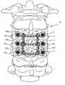
- FIG. 1provides a posterior perspective view of a dynamic stabilization system according to one embodiment of the invention, secured to a portion of a spine;
- FIG. 2Aprovides a posterior perspective view of a bridge element of the dynamic stabilization system of FIG. 1 ;
- FIG. 2Bprovides an anterior view of the bridge element of FIG. 2A ;
- FIG. 2Cprovides a caudal view of the bridge element of FIG. 2A ;
- FIG. 2Dprovides a medial perspective view of the bridge element of FIG. 2A ;
- FIG. 3Aprovides a caudal view of a bridge element and two anchoring members of the dynamic stabilization system of FIG. 1 ;
- FIG. 3Bprovides an exploded perspective view of an anchoring member of FIG. 3A ;
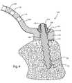
- FIG. 4provides an enlarged caudal cross-sectional view of a portion of the bridge element and one anchoring member of FIG. 3A , anchored in a vertebra;
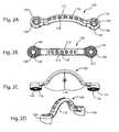
- FIG. 5Aprovides an enlarged perspective view of an elastically deformable bias element of FIG. 1 ;
- FIG. 5Bprovides an enlarged perspective view of an alternate embodiment of an elastically deformable bias element
- FIG. 5Cprovides an enlarged perspective view of an alternate embodiment of an elastically deformable bias element
- FIG. 5Dprovides an enlarged perspective view of an alternate embodiment of an elastically deformable bias element
- FIG. 6provides a partially exploded perspective view of a bridge element, two bias elements, two attachment mechanisms and two anchoring members of the dynamic stabilization system of FIG. 1 ;
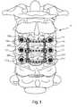
- FIG. 7provides a posterior perspective view of an alternate embodiment of a dynamic stabilization system, comprising two elastically deformable bias elements and two rigid bias elements, anchored to a portion of a spine;
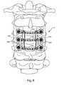
- FIG. 8provides a posterior perspective view of an alternate embodiment of a stabilization system, comprising four bias elements, anchored to a portion of a spine;
- FIG. 9provides a posterior perspective view of an alternate embodiment of a dynamic stabilization system, comprising two bias elements attached to bridge elements at the vertebral midline, anchored to a portion of a spine;
- FIG. 10provides a posterior perspective view of an alternate embodiment of a dynamic stabilization system, comprising two elastically deformable bias elements attached to cross each other at one vertebral level, and two rigid bias elements at a second vertebral level, anchored to a portion of a spine;
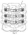
- FIG. 11provides a posterior perspective view of an alternate embodiment of a dynamic stabilization system comprising a bias element extending across two vertebral levels, anchored to a portion of a spine;
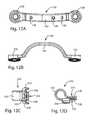
- FIG. 12Aprovides a posterior perspective view of a bridge element of the dynamic stabilization system of FIG. 11 ;
- FIG. 12Bprovides a caudal perspective view of the bridge element of FIG. 12A ;
- FIG. 12Ca perspective view of a clamp of the dynamic stabilization system of FIG. 11 ;
- FIG. 12Dprovides a perspective view of the clamp of FIG. 12C ;
- FIG. 13provides a perspective view of an alternate embodiment of a dynamic stabilization system comprising two elastically deformable bias elements extending across two vertebral levels, anchored to a portion of a spine, and a tensioning tool;
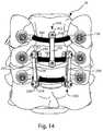
- FIG. 14provides a posterior perspective view of an alternate embodiment of a dynamic stabilization system, anchored to a portion of a spine;
- FIG. 15Aprovides a posterior perspective view of a bridge element of the dynamic stabilization system of FIG. 14 ;
- FIG. 15Bprovides a perspective view of a portion of the bridge element of FIG. 15A ;
- FIG. 15Ca perspective view of a clamp of the dynamic stabilization system of FIG. 14 ;
- FIG. 15Dprovides a perspective view of the clamp of FIG. 15C .
- the present inventionrelates to systems and methods for providing dynamic stabilization between spinal segments.
- Those of skill in the artwill recognize that the following description is merely illustrative of the principles of the invention, which may be applied in various ways to provide many different alternative embodiments. This description is made for the purpose of illustrating the general principles of this invention and is not meant to limit the inventive concepts in the appended claims.
- the systemallows semi-constrained motion between the spinal segments, preserving the normal mobility of the spine, while providing a restoring force that prevents post-operative kyphosis as well as allows correction of pre-existing deformity in the sagittal and/or coronal planes.
- the systemprovides motion restoration with the addition of balance control.
- lateral mass screwsmay be placed with a modified Magerl technique using anatomic landmarks.
- Laminectomymay be performed following placement of the screws and the decompression is achieved. Alternately, screws may be placed first, followed by laminectomy.
- the novel posterior cervical dynamic stabilization systemis affixed to the cervical spine. In the lumbar or thoracic spine, the novel posterior dynamic stabilization system could be affixed via pedicle screws. The following novel embodiments could be easily adapted for the lumbar and thoracic spines.
- a posterior dynamic stabilization system 10secured to a portion of a spine.
- laminectomyhas been performed on the C3, C4 and C5 cervical vertebrae.
- the system 10comprises at least two bridge elements 100 , each of which is sized and shaped to span medial-laterally across the resected vertebra between the lateral masses.
- Each bridge element 100comprises a first anchoring feature 106 , a second anchoring feature 108 , and a bridge body 110 extending between and connecting the anchoring features.
- Each bridge element 100may be secured to a vertebra by at least one anchoring member 150 .
- Each anchoring member 150may comprise an anchor or screw sized and shaped to be received in an anchoring feature 106 or 108 , and may interface with the anchoring feature to secure the bridge element 100 to the bone.
- At least one bias element 200is attached at one end to one bridge element 100 , and at another end to a second bridge element 100 , via attachment mechanisms 300 .
- Each bias element 200may be elastically deformable to provide dynamic stabilization between the vertebrae involved.
- one or more bias elementsmay comprise a more rigid material to provide a stiffer degree of stabilization.
- the system 10 depicted in FIG. 1includes four elastically deformable bias elements, allowing semi-constrained motion between the spinal segments, preserving the normal mobility of the spine.
- the distribution of the bias elementsmay be symmetrical as seen in FIG. 1 , while alternative embodiments include asymmetrically arranged bias elements.
- Bridge element 100may be referred to as a laminar bridge, and is essentially a prosthetic lamina to replace the lamina that has been removed during the laminectomy for decompression.
- the laminar bridgepreferably includes bone ingrowth contact areas that contact the bone and encourage long-term bony fixation, areas which are ideally located on the anterior faces near the bone anchor attachment location, in order to contact the posterior aspects of the lateral masses.
- the laminar bridgeis shaped to be situated well above the thecal sac to prevent any contact with the dura.
- Bridge element 100may comprise titanium, stainless steel, aluminum, cobalt chrome, Nitinol, PEEK (poly ether ether ketone), UHMWPE (ultra high molecular weight polyethylene), or other suitable sufficiently rigid biocompatible materials.
- a bridge elementmay comprise an elastically deformable material.
- the bridge elementsmay take many forms other than those depicted here to accomplish the same function.
- a bridge elementmay comprise two or more parts instead of the monolithic version shown.
- the bridgemay be tubular in form or include hollow portions to improve radiographic visualization if needed.
- the size of each bridge elementcan vary as needed. For example, in some cases, such as when a greater clearance of the dural sac is required on one side of the vertebra, a wider and/or longer anchoring feature may be required on such one side.
- the length, width, thickness and/or height of the bridge bodymay vary as required by patient anatomy or as needed for a desired correction.
- a bridge elementmay be medial-laterally symmetrical as depicted in FIGS. 2A-2D , or asymmetrical as needed.
- Each bridge element 100comprises a first end 102 having an anchoring feature 106 , and a second end 104 having an anchoring feature 108 .
- the bridge element 100further comprises a posterior side 112 and a generally opposite anterior side 114 .
- a plurality of individual discretely located attachment features 118are distributed along the bridge body 110 .
- the attachment featureswhich may be threaded to engage corresponding threads on an attachment mechanism, may be distributed evenly or unevenly along the bridge body.
- anchoring feature 106includes an aperture 116 extending from the posterior side to the anterior side of the bridge element.
- the aperture 116 depictedis substantially cylindrical; however in other embodiments the aperture may be tapered to accommodate polyaxial adjustability of an anchoring member received in the aperture.
- a concave cutout 120encircles the aperture opening. The cutout 120 allows for polyaxial adjustment of the anchoring member, and is faceted to interface with a correspondingly faceted surface of the anchoring member.
- the cutoutmay include surface features such as divots, splines, knurling, longitudinal grooves, circumferential grooves, facets, nubs, and combinations thereof, and/or include surface treatments, roughening or excoriation to promote gripping contact between the anchoring feature and the anchoring member, and to prevent unintended backout of the anchoring member.
- the anterior surface of the anchoring feature 106includes a bone apposition portion 122 .
- the bone apposition portion 122may be knurled as depicted in FIGS. 2B and 2C , and/or may include features such as roughening, excoriation, porous structures or treatments such as porous titanium coating, plasma-sprayed titanium, hydroxylapatite coating, tricalcium phosphate coating, to promote gripping contact and to promote bony ingrowth for long-term fixation.
- the anterior surface of the anchoring feature 106may be angled relative to the posterior surface of the bridge element, to optimally correspond to the natural or resected bone surface to which it is secured during implantation.
- Anchoring feature 108found at the second end 104 of the bridge element 100 , includes aperture 124 and bone apposition portion 126 , which correspond to those of anchoring feature 106 .
- bridge body 110extends medial-laterally between anchoring feature 106 and anchoring feature 108 .
- Bridge body 110is curved or arched to avoid contact with the dura when implanted, and a posterior height h of the curve or arch may exceed the height of the removed natural lamina.
- the attachment features 118 depictedare holes, which may include threads for engagement with threaded attachment members. Other embodiments may include attachment features which are at continuous non-discrete locations along the bridge body.
- attachment featuresconfigured to engage various attachment mechanisms such as clamps, threaded fasteners, locking nuts, posts, holes, press-fits, quick-release and quick-attachment connections, 1 ⁇ 4-turn connections, t-slots, dovetail joints, living hinges, and flanges, among others. All of the attachment features 118 may be medially offset from the anchoring features 106 , 108 when the bridge element 100 is properly secured to a vertebra in the manner set forth herein, that is, in a medial-lateral orientation so as to span the vertebra.
- a single bridge element 100may be secured by two anchoring members 150 .
- anchoring member 150comprises bone anchor 152 and nut 154 , which may be a locking nut.
- Bone anchor 152comprises distal threaded portion 156 , proximal threaded shank 158 , and drive feature 160 .
- drive feature 160is an external hex drive and is positioned between the distal and proximal threaded portions; however in other embodiments the drive feature may be internal and/or comprise a different shape or location.
- an alternate anchoring membermay comprise a screw with a proximally located internal drive feature having a rectangular, triangular or pentagonal shape.
- suitable screw-type bone anchorsmay include lateral mass screws, monoaxial bone screws, polyaxial bone screws, screws with spherical heads, pedicle screws, screws with trilobular or lobular heads, tulip heads, proximal shanks, nuts, slots, serrations, or grooves, among others.
- anchoring membersmay be substituted for bone screws, such as staples, wires, cable, clamps, or hooks, among others.
- Anchoring membersmay include structures to assist in long-term fixation, including but not limited to porous titanium coating, plasma-sprayed titanium, hydroxylapatite coating, tricalcium phosphate coating, porous structures and/or rough surface treatments.
- Nut 154comprises an internal lumen 162 shaped to engage with the bone anchor 152 .
- internal lumen 162is threaded such that it may threadedly engage the proximal threaded portion 158 of the bone anchor 152 .
- Nut 154further comprises a drive portion 164 and an interface portion 166 .
- the interface portion 166is convex and comprises surface facets which correspond to the faceting of concave cutout 120 on the bridge element.
- interface portion 166may comprise facets, and/or other surface features such as divots, splines, knurling, longitudinal grooves, circumferential grooves, facets, nubs, and combinations thereof, and/or include surface treatments, roughening or excoriation.
- FIG. 4a cross-sectional view of an anchoring member 150 in engagement with a bridge member 100 is shown.
- Distal threaded portion 156 of bone anchor 152is engaged in a bone, and anchoring feature 106 is placed over the bone screw such that aperture 116 surrounds drive feature 160 and bone apposition portion 122 contacts the surface of the bone.
- Nut 154is threaded onto the proximal threaded shank 158 to secure bridge member 100 to the bone, and convex interface portion 166 engages with concave cutout 120 .
- the inner diameter of concave cutout 120is greater than the outer diameter of convex interface portion 166 , to allow for polyaxial positioning of anchoring member 150 .
- aperture 116may also be tapered at its distal, or bone-engaging, end to also allow polyaxial placement of anchoring member 150 .
- bias element 200comprises a compliant, elastically deformable material which allows constrained motion between the first and second bridge elements.
- compliant, elastically deformable materialsmay include elastomers, silicones, urethanes, bio-absorbable materials, woven textile structures, knit textile structures, braided textile structures, molded thermoplastic polymers, ethylene-vinyl acetate, PEEK, or UHMWPE; and materials such as Nitinol, titanium, and stainless steel formed into elastically deformable structures such as springs.
- the bias elementis intended to replicate or partially simulate the natural posterior tension band in order to place physiologic constraints to motion and balance once these natural structures have been compromised after surgery.
- the preferred embodimentincludes a compliant material which is suited for tension/extension, such as a silicone or elastomer.
- the bias elementis preferably configured with two attachment ends to be secured to the laminar bridges, as well as a central portion which may be bowed posteriorly in order to encourage buckling in posterior direction during patient extension.
- the bias elementincurs tensile forces and the bias element resists those partially incurring deflection and allowing the flexion to occur.
- the bias elementmay allow all anatomic range of motions seen in the spine including flexion, extension, lateral bending and rotation.
- the bias elementmay have a restoring force, preventing the development of post-laminectomy deformity.
- the geometry of the bias elementmay be configured to provide a correcting force in all planes for correction of sagittal and coronal deformities.
- Bias element 200comprises a first fixation portion 202 , a second fixation 204 and a bias body 206 extending between the first and second fixation portions.
- the first and second fixation portions 202 , 204are each formed from a rigid material which is substantially more rigid and less compliant than the elastically deformable material.
- Such rigid materialsmay include titanium, stainless steel, aluminum, cobalt chromium, Nitinol, PEEK, and UHMWPE, among others.
- Each fixation portion 202 , 204comprises a joining feature 208 , which in the embodiment shown, is a hole.
- the joining feature 208is configured to cooperate with an attachment mechanism to join or attach the bias element to a bridge element.
- the bias body 206 of bias element 200comprises five separate strands of an elastically deformable material.
- Other embodiments of the bias elementmay include more or fewer strands, and/or strands which are woven, braided, knit, or otherwise intertwined.
- bias element 210comprises a bias body 212 having accordion-type folds or pleats.
- FIG. 5Cillustrates a bias element 220 with a substantially flat bias body 222
- FIG. 5Dillustrates a bias element 230 having a bias body 232 with a flexure 234 . It is appreciated that each material used, and/or configurations of the bias body, may be mixed and matched to provide bias elements with varying degrees of elasticity as necessary for the amount of motion and/or correction desired.
- bias elementswithin in the scope of the invention may have different cross-sectional geometries as well, such as circular, rectangular, ovoid, annular, or any freeform shape, as well as being solid, hollow, or porous. Also, bias elements may vary in length and/or width to provide varying degrees of elasticity or compliance.
- An alternative embodiment of the inventionmay include at least one bias element which is formed entirely of rigid materials, in order to provide additional motion or balance control constraints on the functional spinal unit, or motion segment, involved.
- Rigid materials suitable for such a more rigid, less compliant bias elementinclude titanium, stainless steel, aluminum, cobalt chromium, Nitinol, PEEK, and UHMWPE, among others.
- a rigid bias membermay be monolithically formed as one piece, or may include a body portion and fixation portions which are rigidly joined together.
- a system comprising rigid bias elements coupled between bridge elementsmay provide a rigid stabilizing force between the bridge elements. It is appreciated that compliant and rigid bias elements may be mixed and matched to achieve the customized needs of the patient in a multi-level procedure.
- the bias element(s)may be configured to specifically introduce sagittal (lordosis or kyphosis) or coronal balance. Alternatively, or in addition, the bias element(s) may introduce anterior or posterior translation.
- the shaft 314may be inserted through joining feature 208 , then screw 310 and bias element 200 are moved together toward the bridge element and the screw 310 engaged with the attachment feature 118 to attach the bias element to the bridge element.
- the joining feature 208 of the bias element 200may not be threaded, to allow angular adjustment of the bias element relative to the bridge elements before the position of the bias element is fixed by engaging the attachment mechanism 300 with the attachment feature 118 .
- Attachment mechanism 300may be a self-locking screw, or may comprise a locking washer, or backup nut to ensure locking engagement with the bias member and the bridge element, and to prevent unintended backout or removal of the attachment mechanism. It is appreciated that attachment mechanism 300 is removable to provide for revision or adjustment of the bias element relative to the bridge elements. It is also appreciated that other attachment mechanisms exist to secure the bias element to the laminar bridge, including but not limited to clamps, clips, threaded fasteners, posts, holes, press-fits, quick-release and quick-attachment connections, 1 ⁇ 4-turn connections, t-slots, dovetail joints, living hinges, and flanged connections.
- system 10may be implanted as follows.
- the cervical vertebraeare exposed, and bone anchors 152 are placed with a modified Magerl technique using anatomic landmarks.
- Laminectomyis then performed following placement of the anchors, and decompression is achieved.
- laminectomymay first be performed followed by placement of the anchors.
- Bridge elements 100are placed over the bone anchors and secured to the resected vertebrae by nuts 154 .
- Two bridge elements 100may be secured to adjacent vertebrae for single level stabilization, or three or more bridge elements may be used to provide stabilization across multiple levels.
- Bias elements 200are attached to the bridge elements via attachment mechanisms 150 .
- Each bias elementmay be attached to the bridge elements such that it extends essentially perpendicular to the bridge elements, as in FIG. 1 , or may be attached in a non-perpendicular position. As bias elements are attached, tension may be applied manually or with a tensioning tool to achieve a desired tension between the bridge elements.
- the implantation methods set forth hereinmay be applied to any of the posterior dynamic stabilization systems or variations disclosed.
- FIGS. 7-14show alternative embodiments of posterior dynamic stabilization systems.
- system 12comprises three bridge elements 100 secured to three respective vertebrae.
- Elastically deformable bias elements 200are secured bilaterally between the first and second bridge elements, to provide dynamic stabilization at that vertebral level.
- Rigid bias elements 400are secured bilaterally to the second and third bridge elements, to provide rigid stabilization at that vertebral level.
- Another alternative embodimentcould include elastically deformable bias elements secured to bridges at one vertebral level, and different elastically deformable bias elements with a lower or higher degree of elasticity, at a second vertebral level.
- system 14comprises three bridge elements 100 secured to three respective vertebrae.
- Rigid bias elements 400are secured bilaterally to the first and second bridge elements and to the second and third bridge elements, to provide rigid stabilization at both vertebral levels.
- the bridge elementsmay comprise elastically deformable material while the bias elements comprise rigid material, to provide dynamic stabilization at both vertebral levels.
- system 16comprises three bridge elements 100 secured to three respective vertebrae.
- An elastically deformable bias element 200is attached to the first and second bridge elements, aligned with the midline or sagittal plane of the vertebrae and the bridge elements.
- a second elastically deformable bias element 200is attached to the second and third bridge elements, and is also aligned with the midline or sagittal plane of the vertebrae and the bridge elements. It is appreciated that the second deformable bias element may have the same, or different, elasticity as the first bias element.
- Another alternative embodimentcould include rigid bias elements 400 aligned along the midline or sagittal plane at one or both vertebral levels.
- system 18comprises three bridge elements 100 secured to three respective vertebrae.
- a cephalad end of an elastically deformable bias element 200is attached to the first bridge element, and a caudal end is attached to the second bridge element at a location medial-laterally offset from the first location.
- a second elastically deformable bias element 200is attached in an opposite manner, so that the second bias element crosses over the first bias element.
- Two rigid bias elementsextend between the second and third bridge elements to provide rigid stabilization at that level.
- FIGS. 11-14depict posterior dynamic stabilization systems which each include a continuous length of elastically deformable material which is attached across two vertebral levels.
- system 20comprises three bridge elements 130 , each of which is oriented medial-laterally across a vertebra and secured to the vertebra via two anchoring members.
- a bias element 240extends across all three bridge elements at a midline or sagittal position, and is coupled to each bridge element by an attachment mechanism 320 .
- Attachment mechanism 320comprises a clamp 322 and a screw 324 . The screw engages the clamp and the bridge element to both attach the clamp to the bridge element and attach the bias element to the clamp at a desired tension.
- Bridge element 130is shown in FIGS. 12A and 12B .
- Bridge 130comprises a first end having an anchoring feature 136 , and a second end having an anchoring feature 138 .
- a plurality of individual discretely located attachment features 148are distributed along a bridge body 140 .
- the attachment featureswhich may be threaded to engage corresponding threads on an attachment mechanism, may be distributed evenly or unevenly along the bridge body.
- the bridge body 140 of bridge element 130is flatter than bridge body 110 of bridge element 100 . This flatter configuration helps to compensate for the anterior-posterior dimension of the clamp in order to provide a suitably low profile implant.
- Openings 330 , 332are sized and shaped to receive a shaft of screw 324 .
- clamp 322is positionable on a bridge element at an attachment feature 148 , with stops 334 , 336 positioned on either cephalad/caudal side of the bridge element.
- Bias element 240is insertable through the loop portion 325 .
- Screw 324is insertable through clamp openings 330 , 332 and into the attachment feature 148 . When screw 324 is tightened, loop portion 325 closes around bias element 240 , and clamp 322 is rigidly attached to the bridge element, unable to rotate or translate.
- attachment mechanismsexist to secure the bias element to the bridge, including but not limited to clamps, clips, threaded fasteners, posts, holes, press-fits, quick-release and quick-attachment connections, 1 ⁇ 4-turn connections, t-slots, dovetail joints, living hinges, and flanged connections.
- Bias element 240may comprise a single piece or multiple pieces of an elastically deformable material.
- the material composition, length, width, and/or elasticity of bias element 240may vary as needed to attain the desired tension for balance control, deformity correction or other desired outcome.
- posterior dynamic stabilization system 22comprises three bridge elements 131 , 132 , and 133 , bias elements 240 and 242 , assembled with a plurality of anchoring members and attachment mechanisms.
- Attachment mechanisms 341 , 342 , 343 , 344 , 345 and 346may each comprise an attachment mechanism 320 .
- Bias element 240has been tensioned and attached to the three bridge elements by attachment mechanisms 341 , 342 , 343 to provide tension at two vertebral levels.
- Bias element 242comprises a length of elastically deformable material. During an implantation process, bias element 242 may be inserted through the loop portions of attachment mechanisms 344 , 345 , 346 .
- the attachment mechanism 344 on bridge element 131may be tightened to firmly hold the bias element 242 .
- a tensioning tool 450may be coupled to a portion of the bias element, and actuated to provide tension to the bias element.
- the tensioning tool 450comprises a spring 452 , the tool configured such that deflection of the spring provides tension to the bias element.
- the spring deflectionmay be viewed through a window or slot in the tool and a measurement scale may be present on the tool to indicate the magnitude of tension on the bias element.
- the attachment mechanism 345 on bridge element 132may be tightened to lock down the bias element 242 at the desired tension.
- bias element 242may be adjusted between bridge element 132 and 133 by actuation of the tensioning tool, and attachment mechanism 346 tightened to lock down the bias element 242 at the desired tension. Bias element 242 may then be severed between attachment mechanism 346 and the tensioning tool. It is appreciated that bias element may be attached in the same manner as bias element 242 , and that the bias elements 240 , 242 can be inserted, tensioned and locked down in a cephalad-to-caudal order, or vice versa. It is also appreciated that a third bias element may be added to the system to provide additional dynamic support if desired.
- System 24comprises three bridge elements 180 , each secured in a medial-lateral orientation to a vertebra by anchoring members 150 .
- a single bias element 250is attached to first and second bridge elements 180 in a midline position.
- Two additional bias elements 250are attached to the second and third bridge elements in a bilateral arrangement.
- Attachment mechanisms 350which comprise clamp 352 and screw 354 , attach the bias elements 250 to the bridge elements 180 .
- Each bias element 250comprises a first fixation portion 252 , a second fixation portion 254 , and a bias body 256 , and each fixation portion comprises a joining feature 258 .
- FIGS. 15A-15Dshow the details of bridge element 180 and clamp 352 .
- Bridge element 180comprises a first end 182 having an anchoring feature 184 , and a second end 186 having an anchoring feature 188 .
- Bridge body 190has a circular cross-section, and an outer connection surface 192 .
- the connection surface 192is ridged in order to promote a non-slipping grip connection between the bridge body and the attachment mechanism(s) 340 .
- connection surface 192may comprise other gripping features such as knurling, longitudinal grooves, facets, nubs, and combinations thereof, and/or include surface treatments, roughening or excoriation.
- the attachment mechanisms 350can be attached to the bridge element 180 at any location along the bridge body 190 , thus providing a plurality of continuous non-discrete attachment locations. This configuration allows the practitioner to select the precise attachment location needed to produce the desired result, whether it is balance control, deformity correction or a combination.
- clamp 352comprises an open loop portion 356 sized to surround a portion of a bridge body 190 .
- a first tab 358 and a second tab 360are continuations of the loop portion 356 .
- Tab 358has an opening 362
- tab 360has an opening 364 , and the tabs are positioned relative to one another such that the openings are axially aligned.
- Openings 362 , 364are sized and shaped to receive a shaft of screw 354 .
- clamp 352is positionable on a bridge body 180 at any non-discrete location along the body.
- One joining feature 258 of a bias element 250may be placed adjacent the openings 362 , 364 of the clamp 352 .
- Screw 354is insertable through the joining feature 258 and the clamp openings 362 , 364 .
- loop portion 356closes around the bridge body 190
- clamp 352is rigidly attached to the bridge element.
- clamp 352Prior to tightening, clamp 352 may be rotated about the bridge body 190 to a desired position. This rotation allows for tension adjustment of the bias element 250 between the two bridge elements 180 .
- the positions of the attachment mechanisms along the lengths of bridge bodiesmay be adjusted, as can the rotational position of the attachment mechanism, by loosening the screw 354 , making the desired adjustment(s), and re-tightening the screw.
- the second joining feature of bias element 250is attached to a second bridge 180 in a similar fashion.
- attachment mechanismsexist to secure the bias element to the bridge, including but not limited to clamps, clips, threaded fasteners, locking nuts, posts, holes, press-fits, quick-release and quick-attachment connections, 1 ⁇ 4-turn connections, t-slots, dovetail joints, living hinges, and flanged connections.
Landscapes
- Health & Medical Sciences (AREA)
- Orthopedic Medicine & Surgery (AREA)
- Surgery (AREA)
- Life Sciences & Earth Sciences (AREA)
- Neurology (AREA)
- Medical Informatics (AREA)
- Biomedical Technology (AREA)
- Heart & Thoracic Surgery (AREA)
- Engineering & Computer Science (AREA)
- Molecular Biology (AREA)
- Animal Behavior & Ethology (AREA)
- General Health & Medical Sciences (AREA)
- Public Health (AREA)
- Veterinary Medicine (AREA)
- Nuclear Medicine, Radiotherapy & Molecular Imaging (AREA)
- Prostheses (AREA)
- Surgical Instruments (AREA)
Abstract
Description
Claims (67)
Priority Applications (1)
| Application Number | Priority Date | Filing Date | Title |
|---|---|---|---|
| US12/486,563US8303631B2 (en) | 2008-06-20 | 2009-06-17 | Systems and methods for posterior dynamic stabilization |
Applications Claiming Priority (2)
| Application Number | Priority Date | Filing Date | Title |
|---|---|---|---|
| US7453408P | 2008-06-20 | 2008-06-20 | |
| US12/486,563US8303631B2 (en) | 2008-06-20 | 2009-06-17 | Systems and methods for posterior dynamic stabilization |
Publications (2)
| Publication Number | Publication Date |
|---|---|
| US20090318968A1 US20090318968A1 (en) | 2009-12-24 |
| US8303631B2true US8303631B2 (en) | 2012-11-06 |
Family
ID=41431995
Family Applications (1)
| Application Number | Title | Priority Date | Filing Date |
|---|---|---|---|
| US12/486,563Active2030-09-23US8303631B2 (en) | 2008-06-20 | 2009-06-17 | Systems and methods for posterior dynamic stabilization |
Country Status (4)
| Country | Link |
|---|---|
| US (1) | US8303631B2 (en) |
| EP (1) | EP2303164A4 (en) |
| CA (1) | CA2726387A1 (en) |
| WO (1) | WO2009155360A2 (en) |
Cited By (7)
| Publication number | Priority date | Publication date | Assignee | Title |
|---|---|---|---|---|
| US9717541B2 (en) | 2015-04-13 | 2017-08-01 | DePuy Synthes Products, Inc. | Lamina implants and methods for spinal decompression |
| US20170252167A1 (en)* | 2016-03-03 | 2017-09-07 | Globus Medical, Inc. | Lamina plate assembly |
| US9962192B2 (en) | 2016-03-17 | 2018-05-08 | Medos International Sarl | Multipoint fixation implants |
| US10898232B2 (en) | 2018-03-20 | 2021-01-26 | Medos International Sàrl | Multipoint fixation implants and related methods |
| US11304728B2 (en) | 2020-02-14 | 2022-04-19 | Medos International Sarl | Integrated multipoint fixation screw |
| US11426210B2 (en) | 2019-09-25 | 2022-08-30 | Medos International Sàrl | Multipoint angled fixation implants for multiple screws and related methods |
| US11759333B2 (en)* | 2019-10-11 | 2023-09-19 | Warsaw Orthopedic, Inc. | Spinal implant system and methods of use |
Families Citing this family (79)
| Publication number | Priority date | Publication date | Assignee | Title |
|---|---|---|---|---|
| US7833250B2 (en) | 2004-11-10 | 2010-11-16 | Jackson Roger P | Polyaxial bone screw with helically wound capture connection |
| US8292926B2 (en) | 2005-09-30 | 2012-10-23 | Jackson Roger P | Dynamic stabilization connecting member with elastic core and outer sleeve |
| US10729469B2 (en) | 2006-01-09 | 2020-08-04 | Roger P. Jackson | Flexible spinal stabilization assembly with spacer having off-axis core member |
| US10258382B2 (en) | 2007-01-18 | 2019-04-16 | Roger P. Jackson | Rod-cord dynamic connection assemblies with slidable bone anchor attachment members along the cord |
| US7862587B2 (en) | 2004-02-27 | 2011-01-04 | Jackson Roger P | Dynamic stabilization assemblies, tool set and method |
| US8353932B2 (en) | 2005-09-30 | 2013-01-15 | Jackson Roger P | Polyaxial bone anchor assembly with one-piece closure, pressure insert and plastic elongate member |
| US8876868B2 (en) | 2002-09-06 | 2014-11-04 | Roger P. Jackson | Helical guide and advancement flange with radially loaded lip |
| US7621918B2 (en) | 2004-11-23 | 2009-11-24 | Jackson Roger P | Spinal fixation tool set and method |
| US7377923B2 (en) | 2003-05-22 | 2008-05-27 | Alphatec Spine, Inc. | Variable angle spinal screw assembly |
| US7766915B2 (en) | 2004-02-27 | 2010-08-03 | Jackson Roger P | Dynamic fixation assemblies with inner core and outer coil-like member |
| US7776067B2 (en) | 2005-05-27 | 2010-08-17 | Jackson Roger P | Polyaxial bone screw with shank articulation pressure insert and method |
| US7967850B2 (en) | 2003-06-18 | 2011-06-28 | Jackson Roger P | Polyaxial bone anchor with helical capture connection, insert and dual locking assembly |
| US8926670B2 (en) | 2003-06-18 | 2015-01-06 | Roger P. Jackson | Polyaxial bone screw assembly |
| US7179261B2 (en) | 2003-12-16 | 2007-02-20 | Depuy Spine, Inc. | Percutaneous access devices and bone anchor assemblies |
| US11419642B2 (en) | 2003-12-16 | 2022-08-23 | Medos International Sarl | Percutaneous access devices and bone anchor assemblies |
| US7527638B2 (en) | 2003-12-16 | 2009-05-05 | Depuy Spine, Inc. | Methods and devices for minimally invasive spinal fixation element placement |
| US11241261B2 (en) | 2005-09-30 | 2022-02-08 | Roger P Jackson | Apparatus and method for soft spinal stabilization using a tensionable cord and releasable end structure |
| JP2007525274A (en) | 2004-02-27 | 2007-09-06 | ロジャー・ピー・ジャクソン | Orthopedic implant rod reduction instrument set and method |
| US8152810B2 (en) | 2004-11-23 | 2012-04-10 | Jackson Roger P | Spinal fixation tool set and method |
| US7160300B2 (en) | 2004-02-27 | 2007-01-09 | Jackson Roger P | Orthopedic implant rod reduction tool set and method |
| US7651502B2 (en) | 2004-09-24 | 2010-01-26 | Jackson Roger P | Spinal fixation tool set and method for rod reduction and fastener insertion |
| US8926672B2 (en) | 2004-11-10 | 2015-01-06 | Roger P. Jackson | Splay control closure for open bone anchor |
| US8444681B2 (en) | 2009-06-15 | 2013-05-21 | Roger P. Jackson | Polyaxial bone anchor with pop-on shank, friction fit retainer and winged insert |
| US9168069B2 (en) | 2009-06-15 | 2015-10-27 | Roger P. Jackson | Polyaxial bone anchor with pop-on shank and winged insert with lower skirt for engaging a friction fit retainer |
| US20120029568A1 (en)* | 2006-01-09 | 2012-02-02 | Jackson Roger P | Spinal connecting members with radiused rigid sleeves and tensioned cords |
| WO2006057837A1 (en) | 2004-11-23 | 2006-06-01 | Jackson Roger P | Spinal fixation tool attachment structure |
| US9216041B2 (en) | 2009-06-15 | 2015-12-22 | Roger P. Jackson | Spinal connecting members with tensioned cords and rigid sleeves for engaging compression inserts |
| US7901437B2 (en) | 2007-01-26 | 2011-03-08 | Jackson Roger P | Dynamic stabilization member with molded connection |
| US8105368B2 (en) | 2005-09-30 | 2012-01-31 | Jackson Roger P | Dynamic stabilization connecting member with slitted core and outer sleeve |
| CA2670988C (en) | 2006-12-08 | 2014-03-25 | Roger P. Jackson | Tool system for dynamic spinal implants |
| US8475498B2 (en) | 2007-01-18 | 2013-07-02 | Roger P. Jackson | Dynamic stabilization connecting member with cord connection |
| US8366745B2 (en) | 2007-05-01 | 2013-02-05 | Jackson Roger P | Dynamic stabilization assembly having pre-compressed spacers with differential displacements |
| US10383660B2 (en) | 2007-05-01 | 2019-08-20 | Roger P. Jackson | Soft stabilization assemblies with pretensioned cords |
| US8979904B2 (en) | 2007-05-01 | 2015-03-17 | Roger P Jackson | Connecting member with tensioned cord, low profile rigid sleeve and spacer with torsion control |
| US9060813B1 (en) | 2008-02-29 | 2015-06-23 | Nuvasive, Inc. | Surgical fixation system and related methods |
| AU2010260521C1 (en) | 2008-08-01 | 2013-08-01 | Roger P. Jackson | Longitudinal connecting member with sleeved tensioned cords |
| US11229457B2 (en) | 2009-06-15 | 2022-01-25 | Roger P. Jackson | Pivotal bone anchor assembly with insert tool deployment |
| CN103826560A (en) | 2009-06-15 | 2014-05-28 | 罗杰.P.杰克逊 | Polyaxial Bone Anchor with Socket Stem and Winged Inserts with Friction Fit Compression Collars |
| US8998959B2 (en) | 2009-06-15 | 2015-04-07 | Roger P Jackson | Polyaxial bone anchors with pop-on shank, fully constrained friction fit retainer and lock and release insert |
| US9668771B2 (en) | 2009-06-15 | 2017-06-06 | Roger P Jackson | Soft stabilization assemblies with off-set connector |
| US8636772B2 (en)* | 2009-06-23 | 2014-01-28 | Osteomed Llc | Bone plates, screws, and instruments |
| US8246657B1 (en) | 2009-06-29 | 2012-08-21 | Nuvasive, Inc. | Spinal cross connector |
| EP2485654B1 (en) | 2009-10-05 | 2021-05-05 | Jackson P. Roger | Polyaxial bone anchor with non-pivotable retainer and pop-on shank, some with friction fit |
| US8690924B2 (en)* | 2010-02-04 | 2014-04-08 | Spinefrontier Inc | Spinal screw assembly |
| US9198696B1 (en) | 2010-05-27 | 2015-12-01 | Nuvasive, Inc. | Cross-connector and related methods |
| AU2011299558A1 (en) | 2010-09-08 | 2013-05-02 | Roger P. Jackson | Dynamic stabilization members with elastic and inelastic sections |
| DE102010041264A1 (en)* | 2010-09-23 | 2012-03-29 | Aces Gmbh | Dynamic stabilization device for the spine |
| US9301787B2 (en)* | 2010-09-27 | 2016-04-05 | Mmsn Limited Partnership | Medical apparatus and method for spinal surgery |
| US8491641B2 (en) | 2010-09-28 | 2013-07-23 | Spinofix, Inc. | Pedicle screws and dynamic adaptors |
| US8920475B1 (en)* | 2011-01-07 | 2014-12-30 | Lanx, Inc. | Vertebral fixation system including torque mitigation |
| US9247964B1 (en) | 2011-03-01 | 2016-02-02 | Nuasive, Inc. | Spinal Cross-connector |
| US9387013B1 (en) | 2011-03-01 | 2016-07-12 | Nuvasive, Inc. | Posterior cervical fixation system |
| US9585697B2 (en)* | 2011-04-01 | 2017-03-07 | Rebecca Elizabeth Stachniak | Posterior stabilization systems and methods |
| US9724132B2 (en)* | 2011-08-31 | 2017-08-08 | DePuy Synthes Products, Inc. | Devices and methods for cervical lateral fixation |
| US8911479B2 (en) | 2012-01-10 | 2014-12-16 | Roger P. Jackson | Multi-start closures for open implants |
| US9138325B2 (en)* | 2012-07-11 | 2015-09-22 | Globus Medical, Inc. | Lamina implant and method |
| US9055982B2 (en)* | 2012-09-25 | 2015-06-16 | Warsaw Orthopedic, Inc. | Spinal implant system and methods of use |
| US9757160B2 (en)* | 2012-09-28 | 2017-09-12 | Globus Medical, Inc. | Device and method for treatment of spinal deformity |
| US8911478B2 (en) | 2012-11-21 | 2014-12-16 | Roger P. Jackson | Splay control closure for open bone anchor |
| US10058354B2 (en) | 2013-01-28 | 2018-08-28 | Roger P. Jackson | Pivotal bone anchor assembly with frictional shank head seating surfaces |
| US8852239B2 (en) | 2013-02-15 | 2014-10-07 | Roger P Jackson | Sagittal angle screw with integral shank and receiver |
| US9566092B2 (en) | 2013-10-29 | 2017-02-14 | Roger P. Jackson | Cervical bone anchor with collet retainer and outer locking sleeve |
| US9717533B2 (en) | 2013-12-12 | 2017-08-01 | Roger P. Jackson | Bone anchor closure pivot-splay control flange form guide and advancement structure |
| US9451993B2 (en) | 2014-01-09 | 2016-09-27 | Roger P. Jackson | Bi-radial pop-on cervical bone anchor |
| US10105234B2 (en)* | 2014-03-13 | 2018-10-23 | Warsaw Orthopedic, Inc. | Spinal implant system and methods of use |
| US10064658B2 (en) | 2014-06-04 | 2018-09-04 | Roger P. Jackson | Polyaxial bone anchor with insert guides |
| US9597119B2 (en) | 2014-06-04 | 2017-03-21 | Roger P. Jackson | Polyaxial bone anchor with polymer sleeve |
| EP3203921B1 (en)* | 2014-10-09 | 2020-03-18 | Spinal Developments Pty Ltd | Spinal alignment and securement |
| US9895169B2 (en)* | 2015-08-21 | 2018-02-20 | Globus Medical, Inc. | Self in-fusing pedicle screw implant |
| US10695107B2 (en) | 2015-12-03 | 2020-06-30 | Warsaw Orthopedic, Inc. | Spinal implant system and methods of use |
| US11090166B2 (en)* | 2016-03-03 | 2021-08-17 | Globus Medical, Inc. | Lamina plate assembly |
| EP3636186B1 (en)* | 2017-06-08 | 2024-09-04 | National University Corporation Kobe University | Spinal fusion implant |
| US11076902B2 (en) | 2018-02-22 | 2021-08-03 | Phoenix Spine Holdings, Inc. | Locking screw assembly for facilitating direct lateral interbody fusion procedures |
| US11717372B2 (en) | 2018-02-22 | 2023-08-08 | Phoenix Spine Holdings, Inc. | Shape memory surgical sponge for retracting the dura during a laminectomy procedure |
| US10517651B1 (en)* | 2018-11-12 | 2019-12-31 | Medlastics Llc | Facet joint compression system for spinal stabilization |
| US20230277402A1 (en)* | 2020-06-26 | 2023-09-07 | Mazor Robotics Ltd. | Rotatable fixation bridge |
| US20240307129A1 (en)* | 2021-08-04 | 2024-09-19 | University Of Florida Research Foundation, Incorporated | Neurosurgical navigation system reference array apparatus |
| US11331125B1 (en) | 2021-10-07 | 2022-05-17 | Ortho Inventions, Llc | Low profile rod-to-rod coupler |
| US11883080B1 (en)* | 2022-07-13 | 2024-01-30 | Globus Medical, Inc | Reverse dynamization implants |
Citations (19)
| Publication number | Priority date | Publication date | Assignee | Title |
|---|---|---|---|---|
| US6585769B1 (en) | 1999-04-05 | 2003-07-01 | Howmedica Osteonics Corp. | Artificial spinal ligament |
| US20040049190A1 (en) | 2002-08-09 | 2004-03-11 | Biedermann Motech Gmbh | Dynamic stabilization device for bones, in particular for vertebrae |
| US20050203511A1 (en) | 2004-03-02 | 2005-09-15 | Wilson-Macdonald James | Orthopaedics device and system |
| US20050209694A1 (en) | 2004-03-12 | 2005-09-22 | Loeb Marvin P | Artificial spinal joints and method of use |
| US20060084982A1 (en)* | 2004-10-20 | 2006-04-20 | The Board Of Trustees Of The Leland Stanford Junior University | Systems and methods for posterior dynamic stabilization of the spine |
| US20060084991A1 (en) | 2004-09-30 | 2006-04-20 | Depuy Spine, Inc. | Posterior dynamic stabilizer devices |
| US20060241769A1 (en) | 2003-08-05 | 2006-10-26 | Southwest Research Institute | Artificial functional spinal implant unit system and method for use |
| US20060247637A1 (en) | 2004-08-09 | 2006-11-02 | Dennis Colleran | System and method for dynamic skeletal stabilization |
| WO2006116853A1 (en) | 2005-05-02 | 2006-11-09 | Kinetic Spine Technologies Inc. | Spinal stabilisation implant |
| US20060264948A1 (en) | 2005-05-03 | 2006-11-23 | Williams Lytton A | Bone anchored surgical mesh |
| US20070055373A1 (en) | 2005-09-08 | 2007-03-08 | Zimmer Spine, Inc. | Facet replacement/spacing and flexible spinal stabilization |
| US20070073293A1 (en) | 2003-10-16 | 2007-03-29 | Martz Erik O | System and method for flexible correction of bony motion segment |
| US20070073289A1 (en)* | 2005-09-27 | 2007-03-29 | Depuy Spine, Inc. | Posterior dynamic stabilization systems and methods |
| US20070233089A1 (en) | 2006-02-17 | 2007-10-04 | Endius, Inc. | Systems and methods for reducing adjacent level disc disease |
| US20080114357A1 (en) | 2006-11-15 | 2008-05-15 | Warsaw Orthopedic, Inc. | Inter-transverse process spacer device and method for use in correcting a spinal deformity |
| US20080281358A1 (en)* | 2006-12-11 | 2008-11-13 | Abdou M S | Dynamic spinal stabilization systems and methods of use |
| US20090093819A1 (en) | 2007-10-05 | 2009-04-09 | Abhijeet Joshi | Anisotropic spinal stabilization rod |
| US7867263B2 (en)* | 2007-08-07 | 2011-01-11 | Transcorp, Inc. | Implantable bone plate system and related method for spinal repair |
| US8012181B2 (en)* | 2008-02-26 | 2011-09-06 | Spartek Medical, Inc. | Modular in-line deflection rod and bone anchor system and method for dynamic stabilization of the spine |
Family Cites Families (5)
| Publication number | Priority date | Publication date | Assignee | Title |
|---|---|---|---|---|
| US6755831B2 (en)* | 2001-11-30 | 2004-06-29 | Regents Of The University Of Minnesota | Wrist surgery devices and techniques |
| US7717939B2 (en)* | 2004-03-31 | 2010-05-18 | Depuy Spine, Inc. | Rod attachment for head to head cross connector |
| US7857833B2 (en)* | 2005-10-06 | 2010-12-28 | Abdou M Samy | Devices and methods for inter-vertebral orthopedic device placement |
| WO2007052975A1 (en)* | 2005-11-03 | 2007-05-10 | Dong-Kyu Chin | Fixing device for spinous process |
| US20080039843A1 (en)* | 2006-08-11 | 2008-02-14 | Abdou M S | Spinal motion preservation devices and methods of use |
- 2009
- 2009-06-17USUS12/486,563patent/US8303631B2/enactiveActive
- 2009-06-17EPEP09767669Apatent/EP2303164A4/ennot_activeWithdrawn
- 2009-06-17CACA2726387Apatent/CA2726387A1/ennot_activeAbandoned
- 2009-06-17WOPCT/US2009/047684patent/WO2009155360A2/enactiveApplication Filing
Patent Citations (22)
| Publication number | Priority date | Publication date | Assignee | Title |
|---|---|---|---|---|
| US20060287723A1 (en) | 1999-04-05 | 2006-12-21 | Bone Runner Technologies, LLC | Method of repairing a bone joint |
| US6585769B1 (en) | 1999-04-05 | 2003-07-01 | Howmedica Osteonics Corp. | Artificial spinal ligament |
| US7115142B2 (en) | 1999-04-05 | 2006-10-03 | Bone Runner Technologies, LLC | Method of repairing a bone joint |
| US20040049190A1 (en) | 2002-08-09 | 2004-03-11 | Biedermann Motech Gmbh | Dynamic stabilization device for bones, in particular for vertebrae |
| US20060241769A1 (en) | 2003-08-05 | 2006-10-26 | Southwest Research Institute | Artificial functional spinal implant unit system and method for use |
| US20070073293A1 (en) | 2003-10-16 | 2007-03-29 | Martz Erik O | System and method for flexible correction of bony motion segment |
| US20050203511A1 (en) | 2004-03-02 | 2005-09-15 | Wilson-Macdonald James | Orthopaedics device and system |
| US20050209694A1 (en) | 2004-03-12 | 2005-09-22 | Loeb Marvin P | Artificial spinal joints and method of use |
| US20060247637A1 (en) | 2004-08-09 | 2006-11-02 | Dennis Colleran | System and method for dynamic skeletal stabilization |
| US20060084991A1 (en) | 2004-09-30 | 2006-04-20 | Depuy Spine, Inc. | Posterior dynamic stabilizer devices |
| US20060084982A1 (en)* | 2004-10-20 | 2006-04-20 | The Board Of Trustees Of The Leland Stanford Junior University | Systems and methods for posterior dynamic stabilization of the spine |
| WO2006116853A1 (en) | 2005-05-02 | 2006-11-09 | Kinetic Spine Technologies Inc. | Spinal stabilisation implant |
| US20080132954A1 (en) | 2005-05-02 | 2008-06-05 | Kinetic Spine Technologies, Inc. | Spinal stabilisation implant |
| US20060264948A1 (en) | 2005-05-03 | 2006-11-23 | Williams Lytton A | Bone anchored surgical mesh |
| US20070055373A1 (en) | 2005-09-08 | 2007-03-08 | Zimmer Spine, Inc. | Facet replacement/spacing and flexible spinal stabilization |
| US20070073289A1 (en)* | 2005-09-27 | 2007-03-29 | Depuy Spine, Inc. | Posterior dynamic stabilization systems and methods |
| US20070233089A1 (en) | 2006-02-17 | 2007-10-04 | Endius, Inc. | Systems and methods for reducing adjacent level disc disease |
| US20080114357A1 (en) | 2006-11-15 | 2008-05-15 | Warsaw Orthopedic, Inc. | Inter-transverse process spacer device and method for use in correcting a spinal deformity |
| US20080281358A1 (en)* | 2006-12-11 | 2008-11-13 | Abdou M S | Dynamic spinal stabilization systems and methods of use |
| US7867263B2 (en)* | 2007-08-07 | 2011-01-11 | Transcorp, Inc. | Implantable bone plate system and related method for spinal repair |
| US20090093819A1 (en) | 2007-10-05 | 2009-04-09 | Abhijeet Joshi | Anisotropic spinal stabilization rod |
| US8012181B2 (en)* | 2008-02-26 | 2011-09-06 | Spartek Medical, Inc. | Modular in-line deflection rod and bone anchor system and method for dynamic stabilization of the spine |
Cited By (19)
| Publication number | Priority date | Publication date | Assignee | Title |
|---|---|---|---|---|
| US11116551B2 (en) | 2015-04-13 | 2021-09-14 | DePuy Synthes Products, Inc. | Lamina implants and methods for spinal decompression |
| US9717541B2 (en) | 2015-04-13 | 2017-08-01 | DePuy Synthes Products, Inc. | Lamina implants and methods for spinal decompression |
| US10342584B2 (en) | 2015-04-13 | 2019-07-09 | DePuy Synthes Products, Inc. | Lamina implants and methods for spinal decompression |
| US20170252167A1 (en)* | 2016-03-03 | 2017-09-07 | Globus Medical, Inc. | Lamina plate assembly |
| US10667916B2 (en)* | 2016-03-03 | 2020-06-02 | Globus Medical, Inc. | Lamina plate assembly |
| US11154332B2 (en) | 2016-03-17 | 2021-10-26 | Medos International Sarl | Multipoint fixation implants |
| US12376888B2 (en) | 2016-03-17 | 2025-08-05 | Medos International Sàrl | Multipoint fixation implants |
| US10779861B2 (en) | 2016-03-17 | 2020-09-22 | Medos International Sarl | Multipoint fixation implants |
| US9962192B2 (en) | 2016-03-17 | 2018-05-08 | Medos International Sarl | Multipoint fixation implants |
| US11974784B2 (en) | 2016-03-17 | 2024-05-07 | Medos International Sàrl | Multipoint fixation implants |
| US10898232B2 (en) | 2018-03-20 | 2021-01-26 | Medos International Sàrl | Multipoint fixation implants and related methods |
| US11717327B2 (en) | 2018-03-20 | 2023-08-08 | Medos International Sarl | Multipoint fixation implants and related methods |
| US12256962B2 (en) | 2018-03-20 | 2025-03-25 | Medos International Srl | Multipoint fixation implants and related methods |
| US11426210B2 (en) | 2019-09-25 | 2022-08-30 | Medos International Sàrl | Multipoint angled fixation implants for multiple screws and related methods |
| US11998248B2 (en) | 2019-09-25 | 2024-06-04 | Medos International Sårl | Multipoint angled fixation implants for multiple screws and related methods |
| US11759333B2 (en)* | 2019-10-11 | 2023-09-19 | Warsaw Orthopedic, Inc. | Spinal implant system and methods of use |
| US12390351B2 (en)* | 2019-10-11 | 2025-08-19 | Warsaw Orthopedic, Inc | Spinal implant system and methods of use |
| US11304728B2 (en) | 2020-02-14 | 2022-04-19 | Medos International Sarl | Integrated multipoint fixation screw |
| US12185980B2 (en) | 2020-02-14 | 2025-01-07 | Medos International Sàrl | Integrated multipoint fixation screw |
Also Published As
| Publication number | Publication date |
|---|---|
| US20090318968A1 (en) | 2009-12-24 |
| WO2009155360A3 (en) | 2010-03-04 |
| WO2009155360A2 (en) | 2009-12-23 |
| CA2726387A1 (en) | 2009-12-23 |
| EP2303164A4 (en) | 2013-04-03 |
| EP2303164A2 (en) | 2011-04-06 |
Similar Documents
| Publication | Publication Date | Title |
|---|---|---|
| US8303631B2 (en) | Systems and methods for posterior dynamic stabilization | |
| US9844399B2 (en) | Facet joint implant crosslinking apparatus and method | |
| US7967844B2 (en) | Multi-level posterior dynamic stabilization systems and methods | |
| EP1871253B1 (en) | Interspinous vertebral and lumbosacral stabilization devices | |
| US8740944B2 (en) | Vertebral stabilizer | |
| US8007519B2 (en) | Dynamic spinal stabilization system and method of using the same | |
| US7658754B2 (en) | Method for the correction of spinal deformities using a rod-plate anterior system | |
| US7799055B2 (en) | Minimal spacing spinal stabilization device and method | |
| US8034085B2 (en) | Non-fusion spinal correction systems and methods | |
| US20130103088A1 (en) | Segmental Spinous Process Anchor System and Methods of Use | |
| US20190290329A1 (en) | Spinal Fixation Constructs and Related Methods | |
| US20060271055A1 (en) | Spinal stabilization | |
| US20150297262A1 (en) | Central Structures Spreader for the Lumbar Spine | |
| HK1190592B (en) | Interspinous vertebral and lumbosacral stabilization devices and methods of use | |
| HK1118001B (en) | Interspinous vertebral and lumbosacral stabilization devices | |
| HK1190592A (en) | Interspinous vertebral and lumbosacral stabilization devices and methods of use |
Legal Events
| Date | Code | Title | Description |
|---|---|---|---|
| AS | Assignment | Owner name:DUGGAL, NEIL, CANADA Free format text:ASSIGNMENT OF ASSIGNORS INTEREST;ASSIGNORS:DUGGAL, NEIL;BUTTERS, JOSHUA;FALLIN, T. WADE;AND OTHERS;SIGNING DATES FROM 20090615 TO 20100920;REEL/FRAME:025034/0067 Owner name:MEDICINELODGE, INC, DBA IMDS CO-INNOVATION, UTAH Free format text:ASSIGNMENT OF ASSIGNORS INTEREST;ASSIGNORS:DUGGAL, NEIL;BUTTERS, JOSHUA;FALLIN, T. WADE;AND OTHERS;SIGNING DATES FROM 20090615 TO 20100920;REEL/FRAME:025034/0067 | |
| STCF | Information on status: patent grant | Free format text:PATENTED CASE | |
| FEPP | Fee payment procedure | Free format text:PAYOR NUMBER ASSIGNED (ORIGINAL EVENT CODE: ASPN); ENTITY STATUS OF PATENT OWNER: SMALL ENTITY | |
| AS | Assignment | Owner name:DUGGAL, NEIL, CANADA Free format text:ASSIGNMENT OF ASSIGNORS INTEREST;ASSIGNOR:COORSTEK MEDICAL LLC D/B/A IMDS;REEL/FRAME:033436/0131 Effective date:20140724 | |
| AS | Assignment | Owner name:NEIL DUGGAL, CANADA Free format text:CORRECTIVE ASSIGNMENT TO CORRECT THE CONVEYING PARTY NAME PREVIOUSLY RECORDED AT REEL: 033436 FRAME: 0131. ASSIGNOR(S) HEREBY CONFIRMS THE ASSIGNMENT;ASSIGNOR:IMDS LLC;REEL/FRAME:033525/0686 Effective date:20140813 | |
| FPAY | Fee payment | Year of fee payment:4 | |
| MAFP | Maintenance fee payment | Free format text:PAYMENT OF MAINTENANCE FEE, 8TH YR, SMALL ENTITY (ORIGINAL EVENT CODE: M2552); ENTITY STATUS OF PATENT OWNER: SMALL ENTITY Year of fee payment:8 | |
| AS | Assignment | Owner name:2377469 ONTARIO INC., CANADA Free format text:ASSIGNMENT OF ASSIGNORS INTEREST;ASSIGNOR:DUGGAL, NEIL;REEL/FRAME:054818/0665 Effective date:20201215 | |
| FEPP | Fee payment procedure | Free format text:MAINTENANCE FEE REMINDER MAILED (ORIGINAL EVENT CODE: REM.); ENTITY STATUS OF PATENT OWNER: SMALL ENTITY | |
| FEPP | Fee payment procedure | Free format text:11.5 YR SURCHARGE- LATE PMT W/IN 6 MO, SMALL ENTITY (ORIGINAL EVENT CODE: M2556); ENTITY STATUS OF PATENT OWNER: SMALL ENTITY | |
| MAFP | Maintenance fee payment | Free format text:PAYMENT OF MAINTENANCE FEE, 12TH YR, SMALL ENTITY (ORIGINAL EVENT CODE: M2553); ENTITY STATUS OF PATENT OWNER: SMALL ENTITY Year of fee payment:12 |