US8303601B2 - Collet-activated distraction wedge inserter - Google Patents
Collet-activated distraction wedge inserterDownload PDFInfo
- Publication number
- US8303601B2 US8303601B2US11/448,416US44841606AUS8303601B2US 8303601 B2US8303601 B2US 8303601B2US 44841606 AUS44841606 AUS 44841606AUS 8303601 B2US8303601 B2US 8303601B2
- Authority
- US
- United States
- Prior art keywords
- collet
- handle
- wedge
- shaft
- roller
- Prior art date
- Legal status (The legal status is an assumption and is not a legal conclusion. Google has not performed a legal analysis and makes no representation as to the accuracy of the status listed.)
- Expired - Fee Related, expires
Links
- 238000000034methodMethods0.000claimsdescription18
- 230000000399orthopedic effectEffects0.000claimsdescription12
- 238000010420art techniqueMethods0.000description2
- 230000008569processEffects0.000description2
- 238000001356surgical procedureMethods0.000description2
- RTAQQCXQSZGOHL-UHFFFAOYSA-NTitaniumChemical compound[Ti]RTAQQCXQSZGOHL-UHFFFAOYSA-N0.000description1
- 230000009471actionEffects0.000description1
- 229910045601alloyInorganic materials0.000description1
- 239000000956alloySubstances0.000description1
- 238000004140cleaningMethods0.000description1
- 230000001010compromised effectEffects0.000description1
- 230000004927fusionEffects0.000description1
- 208000014674injuryDiseases0.000description1
- 238000009434installationMethods0.000description1
- 229910001092metal group alloyInorganic materials0.000description1
- 230000004048modificationEffects0.000description1
- 238000012986modificationMethods0.000description1
- 230000008520organizationEffects0.000description1
- 229920003023plasticPolymers0.000description1
- 239000004033plasticSubstances0.000description1
- 210000000278spinal cordAnatomy0.000description1
- 210000001032spinal nerveAnatomy0.000description1
- 239000010935stainless steelSubstances0.000description1
- 229910001220stainless steelInorganic materials0.000description1
- 239000000126substanceSubstances0.000description1
- 239000010936titaniumSubstances0.000description1
- 229910052719titaniumInorganic materials0.000description1
- 230000008736traumatic injuryEffects0.000description1
- 238000003466weldingMethods0.000description1
Images


Classifications
- A—HUMAN NECESSITIES
- A61—MEDICAL OR VETERINARY SCIENCE; HYGIENE
- A61B—DIAGNOSIS; SURGERY; IDENTIFICATION
- A61B17/00—Surgical instruments, devices or methods
- A61B17/02—Surgical instruments, devices or methods for holding wounds open, e.g. retractors; Tractors
- A61B17/025—Joint distractors
- A—HUMAN NECESSITIES
- A61—MEDICAL OR VETERINARY SCIENCE; HYGIENE
- A61B—DIAGNOSIS; SURGERY; IDENTIFICATION
- A61B17/00—Surgical instruments, devices or methods
- A61B2017/0046—Surgical instruments, devices or methods with a releasable handle; with handle and operating part separable
- A61B2017/00473—Distal part, e.g. tip or head
- A—HUMAN NECESSITIES
- A61—MEDICAL OR VETERINARY SCIENCE; HYGIENE
- A61B—DIAGNOSIS; SURGERY; IDENTIFICATION
- A61B17/00—Surgical instruments, devices or methods
- A61B17/02—Surgical instruments, devices or methods for holding wounds open, e.g. retractors; Tractors
- A61B17/025—Joint distractors
- A61B2017/0256—Joint distractors for the spine
Definitions
- the human spinal columnprovides support for the body while also protecting the delicate spinal cord and nerves traveling along the spinal column.
- the spinal columncomprises a series of vertebrae stacked on top of each other with an intervertebral disc between each vertebrae.
- the intervertebral discsadvantageously provide cushioning and dampening of compressive forces to the spinal column.
- the intervertebral discsmay be damaged or otherwise compromised.
- intervertebral disc replacement devicessuch as fusion devices, may be inserted to replace the failing disc or a portion thereof.
- the discmay be removed in whole or in part and the intervertebral disc replacement device inserted between the vertebral bodies. During this procedure, adjacent vertebrae may be distracted by a distraction instrument to assist with the removal process, endplate preparation, or other portions of the procedure.
- Present distraction instrumentsinclude wedges that may be inserted into the disk area for temporarily supporting the spinal structure.
- Conventional wedgesmay be threaded onto an installation tool, which typically comprises an elongated shaft with a handle, the shaft having external threads at its distal end for engagement with internal threads of the wedge.
- an installation tooltypically comprises an elongated shaft with a handle, the shaft having external threads at its distal end for engagement with internal threads of the wedge.
- the toolOnce inserted, the tool may be rotated and unthreaded from the wedge with the wedge left in place temporarily distracting the adjacent vertebrae.
- the unthreading of the tool from the wedge distractoris certainly time consuming and may be difficult because of cross-threading.
- the toolmay be left in place while other portions of the overall procedure are undertaken by the surgeon. However, this leaves the tool in the surgeon's line of sight.
- a device for inserting and removing a distraction wedgecomprising an outer member having a handle and an outer shaft, the outer shaft extending from the handle along a central axis from a proximal end of the outer member to a distal end of the outer member, the handle having a bore, the bore being in-line with the central axis, at least a portion of the bore being internally threaded, the outer shaft having at least one collet formed between a pair of slots extending from the distal end of the outer shaft toward the handle, the at least one collet having a cammed surface on the interior surface thereof.
- the devicealso comprises an inner member having a roller and a rod, the rod extending from the roller along a central axis from a proximal end of the inner member to a head formed at a distal end of the inner member, the rod having a threaded portion configured to mate with the internally threaded portion of the handle such that threading of the rod into the handle serves to advance the rod within the outer member toward the distal end of the outer member, whereby the rod is long enough with respect to the outer shaft that the head interferes with the cammed surface of the at least one collet to move the at least one collet outwardly in a radial direction from the central axis of the outer member.
- the at least one colletmay have a free end at the distal end of the shaft and a fixed end toward the proximal end, the fixed end formed at the proximal limit of the slots.
- the at least one colletmay include a shoulder between the fixed end and the free end.
- the at least one colletmay include a shoulder at the fixed end.
- the shaftmay be comprised of an upper shaft at its proximal end and a lower shaft at its distal end, the upper shaft having a diameter greater than that of the lower shaft.
- the devicemay further comprise a tapered portion between the upper shaft and the lower shaft.
- the handle and the shaftmay form a T-shaped device.
- the rollermay be a hand manipulable roller.
- the at least one colletmay be four collets and the pair of slots may be two of four total slots.
- the handlemay further comprise a cavity, the roller adapted to at least partially fit within the cavity when threaded in the handle.
- a system for spacing orthopedic bodiescomprising at least two wedges, each adapted to be inserted between a first orthopedic body and a second orthopedic body to distract the bodies away from each other, the wedge having an internal cavity; a distraction instrument for engaging with the internal cavity of the wedge, the instrument comprising an outer member and an inner member; the outer member formed from a handle and an outer shaft, the outer shaft extending from the handle along a central axis from a proximal end of the outer member to a distal end of the outer member, the handle having a bore, the bore being in-line with the central axis, at least a portion of the bore being internally threaded, the outer shaft having collets formed between slots which extend from the extreme distal end of the outer shaft toward the handle such that the collets include a free end and a fixed end, the fixed end being at the termination of the slots, the collets having a cammed internal surface; the inner member formed from a roller and a rod, the rod extending
- the colletsmay include shoulders and the wedge may include aperture extensions into which the shoulders may fit.
- the cavity of the wedgemay include inside limits, the shoulders adapted to abut the inside limits when the device is fully inserted into the cavity.
- the handle and the shaftmay form a T-shape.
- the handlemay include a cavity, at least a portion of the roller adapted to fit within the cavity.
- the rollermay abut the handle when the collets are deformed outwardly a sufficient distance to secure the wedge to the device.
- a method of distracting orthopedic bodies with a wedge having an internal cavity and an instrument having at least one collet adapted to fit freely within the cavity while in a first position and to frictionally engage the internal cavity after expanding to a second positioncomprising inserting the at least one collet of the instrument into the internal cavity of the wedge while the collet is in the first position; expanding the at least one collet into the second position to frictionally engage the wedge; inserting the wedge between two orthopedic bodies to distract the bodies.
- the methodmay further comprise retracting the at least one collet from the second expanded position back to the first position; removing the instrument from the wedge.
- the methodmay further comprise inserting the at least one collet of the instrument into the internal cavity of the wedge while the collet is in the first position; expanding the at least one collet into the second position to frictionally engage the wedge; removing the wedge from between the two orthopedic bodies.
- the devicemay further comprise a roller, and expansion of the at least one collet is achieved by rotation of the roller in a first direction.
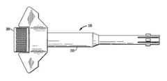
- FIG. 1is a plan view of a fully assembled collet-activated distraction wedge inserter in accordance with certain aspects of the present invention
- FIG. 2is a plan view of an outer member forming a portion of the collet-activated distraction wedge inserter of FIG. 1 , with certain internal portions shown in phantom for clarity;
- FIG. 3is a plan view of an inner member forming a portion of the collet-activated distraction wedge inserter of FIG. 1 ;
- FIG. 4is a partially cut-away plan view of the fully assembled collet-activated distraction wedge inserter of FIG. 1 , with certain internal portions shown in phantom for clarity;
- FIG. 5is a cross-sectional view of the distal end of the outer member shown in FIG. 2 ;
- FIG. 6is a cross-sectional view of the distal end of the outer member shown in FIG. 2 with the inner member shown in FIG. 3 at a first position;
- FIG. 7is a cross-sectional view of the distal end of the outer member shown in FIG. 2 with the inner member shown in FIG. 3 at a second position;
- FIG. 8is a side view of a distraction wedge that may be utilized with the collet-activated distraction wedge inserter of FIG. 1 ;
- FIG. 9is a rear view of the distraction wedge of FIG. 8 ;
- FIG. 10is a partial cross-sectional view of the collet-activated distraction wedge inserter of FIG. 1 partially engaged with the distraction wedge of FIG. 8 .
- the present inventionrelates to distraction wedge inserters, and more specifically collet-activated distraction wedge inserters.
- Such insertersmay be utilized to capture a distraction wedge at a distal end of the inserter, such that the wedge may be inserted between intervertebral bodies to provide access to the vertebrae for the procedure of, for example, implanting a permanent intervertebral disk replacement device. Together, the inserter and wedge distract the vertebral bodies. The inserter may then be temporarily disassociated with the wedge with the wedge left in place. This provides the surgeon with better access and visibility than he would have with the inserter in place. When it is desired that the wedge be removed from the spinal column, the inserter may then be quickly and positively reassociated with the wedge such that the wedge may be removed. In accordance with the present invention, such association of the inserter and wedge is achieved by frictional relation between radially expanding collets of the inserter and an aperture formed in the wedge, as will be discussed more fully below.
- a collet-activated distraction wedge inserter 100may comprise an outer member 200 and an inner member 300 , where the inner member is adapted to fit within the outer member.
- FIG. 2depicts a plan view of the outer member 200 in accordance with a preferred embodiment of the present invention.
- the outer member 200includes a handle 202 and a shaft 204 extending from the handle.
- the shaft 204which has a circular cross-section, extends through the handle 202 from a proximal end 206 of the outer member 200 to a distal end 208 along the length of a longitudinal centerline 207 .
- the shaft 204is hollow such that a bore 210 extends along its entire length from the proximal end 206 to the distal end 208 .
- the bore 210includes a threaded portion 212 which will be discussed in more detail below.
- the shaft 204may be connected to the handle 202 by any conventional biocompatible means, including pressure fit, threading, welding, chemical adhesion, or the like, such that the shaft and handle are virtually inseparable.
- the handle 202is generally formed from a handle base 214 , from which the shaft 204 extends, and handle projections 216 extending outwardly from the handle base 214 to form a cavity 218 at the proximal end 206 of the outer member 200 .
- the cavityis formed from a bearing surface 220 at the handle base 214 and a pair of upstanding walls 222 , formed by the handle projections 216 respectively.
- the handle 202includes a flat front face 203 and a flat rear face (not shown), and forms a generally T-shape with the shaft 204 .
- the device 100 and particularly the associated handle 202are ergonomically configured to permit ease and comfort in use.
- the device 100is also configured to permit one-handed use by grasping of the handle 202 , if so desired.
- the shaft 204is comprised of an upper shaft 224 and an adjacent lower shaft 226 , the upper shaft being closest to the handle 202 . It will be appreciated that the upper shaft 224 is formed to a greater diameter than the lower shaft 226 such that there resides a tapered portion 228 therebetween. At the distal end 208 of the lower shaft 226 , there is formed at least one collet 230 . In the preferred embodiment shown in FIG. 2 , there are four such collets 230 , with the rear-most collet being hidden from view in FIG. 2 .
- the collets 230are created by slots 232 formed in the hollow lower shaft 226 from the distal end 208 and extending toward the proximal end 206 such that each collet 230 includes a distal end 234 at the extreme distal end 208 of the lower shaft 226 and a proximal end 236 at a point toward the tapered portion 228 where the slot 232 ends. Each collet 230 is therefore cantilevered from the remainder of the lower shaft 226 at its respective proximal end 236 .
- the collets 230may each include a shoulder 238 extending outwardly from the collet's outer surface.
- a shouldercan be provided on less than each collet, but there are preferably at least two, and in the preferred embodiment one for each collet.
- the shoulder 238has an extreme outer diameter approximately equal to the diameter of the upper shaft 224 , which, as noted, is greater than the diameter of the lower shaft 226 .
- the shoulders on the colletsmay be replaced with one shoulder or a number of shoulders on the shaft 226 above the collets. Such a shoulder might be a single continuous annular shoulder.
- the shoulders 238may be configured on the collet 230 at the approximate mid-point between the distal end 234 and the proximal end 236 . Alternatively, the shoulders 238 may be configured at the proximal end 236 of each collet 230 . It will also be appreciated that the shoulders 238 may be located on the lower shaft 226 beyond the limits of the slots 232 , or closer toward the distal end 208 . The number of shoulders 238 may be less than that of the total number of collets 230 , if so desired. Alternatively, the collets 230 may not include shoulders 238 .
- the collet's inner surfaceforms a cammed surface 240 .
- the cammed surface 240is in essence an angled projection having an inner diameter less than that of the inner diameter of the lower shaft 226 .
- the function of the cammed surface 240will be discussed more fully below, but it will be appreciated that a rod that may freely fit within the lower shaft 226 may be cammed against the cammed surface 240 to force open the distal end 234 of each collet and spread apart same radially to create an outer diameter at the distal end 234 which is greater than the outer diameter of the remainder of the lower shaft 226 . This expansion may be utilized to secure a wedge.
- the inner member 300may comprise a roller 302 with a rod 304 extending along a central axis 301 therefrom.
- the roller 302may be formed between a base 306 at intersection of the roller 302 and the rod 304 to an upper limit 308 at a proximal end 310 of the inner member 300 .
- the roller 302may include a knurled portion 312 between the upper limit 308 and the base 306 , the knurled portion 312 being utilized for rotational manipulation by the surgeon.
- the rod 304may comprise an upper rod 314 positioned toward the proximal end 310 of the inner member 300 and a lower rod 316 positioned toward the distal end 318 of the inner member 300 .
- the upper rod 314has an outside diameter greater than that of the lower rod 316 , such that a tapered portion 320 lies therebetween.
- the lower rod 316culminates with a shaped head, such as the convex head 322 shown in FIG. 3 .
- the convex head 322is utilized to spread apart the collets 230 of the outer member 200 by camming against the cammed surface 240 of each collet. It will therefore be appreciated that other geometric shaped heads, such as cone shaped or pyramid shaped heads, may also be utilized suitably for this purpose.
- the upper rod 314also includes a threaded portion 324 adjacent to the roller 302 .
- the inner member 300is adapted to fit within the outer member 200 such that the threaded portion 324 of the upper rod 314 may thread within the threaded portion 212 of the handle 202 . This relationship is shown in FIG. 4 . It will be appreciated that as the inner member 300 is threaded into the outer member 200 , the convex head 322 moves closer to the cammed surface 240 of each collet 230 . When the roller 302 is fully threaded into the handle 202 , such that the base 306 of the roller contacts the bearing surface 220 of the cavity 218 , the convex head 322 will be fully engaged with the cammed surfaces 240 to spread the collets 230 apart.
- the upper limit 308 of the roller 302may be used as an impact surface against which a mallet may be struck when inserting the wedge to help drive the wedge in place.
- the force of the malletwill therefore be transferred from the roller 302 to the bearing surface 220 of the handle 202 , and not to any of the threaded portions 212 , 324 .
- FIG. 5depicts a cross-section of the distal end 208 of lower shaft 226 with the front-most collet 230 removed for clarity. In this view, the cammed surfaces 240 can be seen more clearly than in previous figures.
- FIG. 6also depicts a cross-section of the distal end 208 of lower shaft 226 with the front-most collet 230 removed for clarity, but with the lower rod 316 being inserted into the lower shaft 226 .
- the convex head 322is adjacent to the cammed surface 240 , but has not yet made significant contact as it moves from left to right.
- the convex head 322moves linearly toward the extreme distal end 208 of the lower shaft 226 .
- This movementcauses the convex head 322 to contact the cammed surfaces 240 to spread the cammed surfaces apart so as to expand the collets 230 radially outward at their respective distal ends 234 from fixed positions at the proximal ends 236 .
- This relationshipopens the distal end 208 of the lower shaft such that the outside diameter at the distal end is greater than that of the remainder of the lower shaft 226 . In use, this action spreads the collets 230 to frictionally engage the interior of a cavity, particularly the cavity of a distraction wedge, as will be discussed.
- FIG. 8depicts a distraction wedge 400 suitable for use with the collet-activated distraction wedge inserter 100 described herein.
- distraction wedge 400may include a side portion 402 tapering to an upper limit 404 and a lower limit 406 with an upper taper 408 and a lower taper 410 .
- the distraction wedge 400may extend between a back 412 and a tip 414 , the tip being formed by an upper angled portion 416 extending from the upper limit 404 to the tip 414 and a lower angled portion 418 extending from the lower limit 408 to the tip 414 .
- the back 412may include an aperture 420 .
- the aperture 420is preferably round and with a diameter slightly larger than the outer diameter of the lower shaft 226 , such that the lower shaft may fit within the aperture.
- the aperture 420may also include aperture extensions 422 extending from the aperture 420 to permit the shoulders 238 to also fit within the distraction wedge 400 . It will be appreciated that the shoulders 238 may abut against the inside limit 424 of the aperture extensions 422 to limit the distance in which the lower shaft 226 may enter the aperture 420 . This relationship is best shown in FIG. 10 , where the lower shaft 226 has been inserted into the aperture 420 such that the shoulders 238 abut the inside limit 424 . Once the lower shaft 226 is positioned as shown in FIG.
- the convex head 322 of the lower rod 316may be advanced toward the cammed surfaces 240 of the collets 230 to open the collets such that a frictional force is created between the collets and the interior walls 426 of the aperture 420 . This force serves to hold the distraction wedge 400 in fixed relation with the collet-activated distraction wedge inserter 100 .
- the distraction wedge 400may then be inserted into the spinal cavity of a patient during a surgical procedure to temporarily distract adjacent vertebrae.
- the roller 302may be rotated in a direction opposite to the rotation required to advance the convex head 322 , such that the convex head is retracted into the lower shaft whereby the collets 230 may rebound back to their natural positions with an outside diameter approximately equal to that of the remainder of the lower shaft 226 and removed from the distraction wedge 400 .
- the distal end 208 of the deviceis simply inserted into the aperture 420 of the distraction wedge 400 . Because the distal end 208 of the collet-activated distraction wedge inserter 100 may be fully inserted without any threading, it is very easy to instantly fully seat the distal end 208 within the aperture 420 .
- the distal end of the conventional insertermay be abutted against the aperture of a wedge, the distal end cannot be fully seated without rotating the inserter to fully thread the connection. Surgeons often find that the conventional inserter becomes disassociated with the wedge when such threading is attempted, as the distal end slips off of its engagement with the aperture because the distal end penetrates the aperture only slightly before threading begins.
- the surgeon utilizing a collet-activated distraction wedge inserter of the present inventioneasily ensures that the distal end 208 is fully inserted by simply pushing the distal end 208 into the aperture of the wedge until the shoulders 238 engage the inside limit 424 . At such point, the surgeon may rotate the roller 302 to advance the convex head 322 of the lower rod 316 against the cammed surface 240 of the collets 230 to spread the collets apart. In embodiments where shoulders are not provided, the surgeon may insert the distal end 208 of the collet-activated distraction wedge inserter 200 until the distal end abuts the rear wall 428 of the aperture 420 .
- the collet-activated distraction wedge inserter 100is configured such that the collets 230 are spread apart the optimal distance to create the requisite friction within the aperture 420 at the moment that the base 306 of the roller 302 abuts the bearing surface 220 of the handle 202 . At this point, the surgeon may withdraw the collet-activated distraction wedge inserter 100 from within the body along with the distraction wedge 400 due to the frictional relation between the two members.
- the abutting surfaces of the collets 230 and the aperture 420 of the wedge 400may be textured. It is preferred that such texturing be suitable for cleaning between uses of the collet-activated distraction wedge inserter 100 .
- the components comprising the collet-activated distraction wedge inserter 100may be formed from various biocompatible plastics or metal alloys. Particularly suitable alloys are stainless steel or titanium. Further, it will be appreciated that the inner member 300 may easily be withdrawn from the outer member 200 by completely unthreading the threaded portion 324 of the rod 304 from the threaded portion 212 of the handle 202 and withdrawing the inner member 300 from the outer member 200 such that the components may be cleaned and sterilized.
Landscapes
- Health & Medical Sciences (AREA)
- Life Sciences & Earth Sciences (AREA)
- Surgery (AREA)
- Heart & Thoracic Surgery (AREA)
- Engineering & Computer Science (AREA)
- Biomedical Technology (AREA)
- Nuclear Medicine, Radiotherapy & Molecular Imaging (AREA)
- Medical Informatics (AREA)
- Molecular Biology (AREA)
- Animal Behavior & Ethology (AREA)
- General Health & Medical Sciences (AREA)
- Public Health (AREA)
- Veterinary Medicine (AREA)
- Prostheses (AREA)
- Surgical Instruments (AREA)
Abstract
Description
Claims (20)
Priority Applications (1)
| Application Number | Priority Date | Filing Date | Title |
|---|---|---|---|
| US11/448,416US8303601B2 (en) | 2006-06-07 | 2006-06-07 | Collet-activated distraction wedge inserter |
Applications Claiming Priority (1)
| Application Number | Priority Date | Filing Date | Title |
|---|---|---|---|
| US11/448,416US8303601B2 (en) | 2006-06-07 | 2006-06-07 | Collet-activated distraction wedge inserter |
Publications (2)
| Publication Number | Publication Date |
|---|---|
| US20080071279A1 US20080071279A1 (en) | 2008-03-20 |
| US8303601B2true US8303601B2 (en) | 2012-11-06 |
Family
ID=39189613
Family Applications (1)
| Application Number | Title | Priority Date | Filing Date |
|---|---|---|---|
| US11/448,416Expired - Fee RelatedUS8303601B2 (en) | 2006-06-07 | 2006-06-07 | Collet-activated distraction wedge inserter |
Country Status (1)
| Country | Link |
|---|---|
| US (1) | US8303601B2 (en) |
Cited By (40)
| Publication number | Priority date | Publication date | Assignee | Title |
|---|---|---|---|---|
| US20130289634A1 (en)* | 2007-05-02 | 2013-10-31 | Zimmer, Inc, | Orthopedic tool for altering the connection between orthopedic components |
| US20140081278A1 (en)* | 2012-09-14 | 2014-03-20 | Biomet Manufacturing Corp. | Acetabular cup inserter handle |
| US20140172107A1 (en)* | 2009-10-02 | 2014-06-19 | Amedica Corporation | Biomedical implant inserters and related apparatus, systems, and methods |
| US9186484B2 (en) | 2010-07-01 | 2015-11-17 | DePuy Synthes Products, Inc. | Guidewire insertion methods and devices |
| US9289249B2 (en) | 2013-03-14 | 2016-03-22 | DePuy Synthes Products, Inc. | Bone anchors and surgical instruments with integrated guide tips |
| US9358123B2 (en) | 2011-08-09 | 2016-06-07 | Neuropro Spinal Jaxx, Inc. | Bone fusion device, apparatus and method |
| US20160310180A1 (en)* | 2015-04-24 | 2016-10-27 | Meditech Spine, Llc | Anterior spinal bone plate holding system and method |
| US9526525B2 (en) | 2006-08-22 | 2016-12-27 | Neuropro Technologies, Inc. | Percutaneous system for dynamic spinal stabilization |
| US9532883B2 (en) | 2012-04-13 | 2017-01-03 | Neuropro Technologies, Inc. | Bone fusion device |
| US9788971B1 (en) | 2013-05-22 | 2017-10-17 | Nuvasive, Inc. | Expandable fusion implant and related methods |
| US9801734B1 (en) | 2013-08-09 | 2017-10-31 | Nuvasive, Inc. | Lordotic expandable interbody implant |
| US9855087B2 (en) | 2014-08-04 | 2018-01-02 | DePuy Synthes Products, LLC | Methods and devices for spinal screw insertion |
| US20180028202A1 (en)* | 2016-08-01 | 2018-02-01 | Howmedica Osteonics Corp. | Centering guide system for arthroplasty |
| US9974665B2 (en) | 2004-11-03 | 2018-05-22 | Neuropro Technologies, Inc. | Bone fusion device |
| US10045768B2 (en) | 2014-07-06 | 2018-08-14 | Javier Garcia-Bengochea | Methods and devices for surgical access |
| US10098757B2 (en) | 2013-03-15 | 2018-10-16 | Neuropro Technologies Inc. | Bodiless bone fusion device, apparatus and method |
| US10111760B2 (en) | 2017-01-18 | 2018-10-30 | Neuropro Technologies, Inc. | Bone fusion system, device and method including a measuring mechanism |
| US10159583B2 (en) | 2012-04-13 | 2018-12-25 | Neuropro Technologies, Inc. | Bone fusion device |
| US10195053B2 (en) | 2009-09-18 | 2019-02-05 | Spinal Surgical Strategies, Llc | Bone graft delivery system and method for using same |
| US10213321B2 (en) | 2017-01-18 | 2019-02-26 | Neuropro Technologies, Inc. | Bone fusion system, device and method including delivery apparatus |
| US10245159B1 (en) | 2009-09-18 | 2019-04-02 | Spinal Surgical Strategies, Llc | Bone graft delivery system and method for using same |
| US10292830B2 (en) | 2011-08-09 | 2019-05-21 | Neuropro Technologies, Inc. | Bone fusion device, system and method |
| US10420654B2 (en) | 2011-08-09 | 2019-09-24 | Neuropro Technologies, Inc. | Bone fusion device, system and method |
| US10433883B2 (en) | 2017-06-27 | 2019-10-08 | Medos International Sarl | Spinal screw insertion devices and methods |
| US10687830B2 (en) | 2015-07-06 | 2020-06-23 | Javier Garcia-Bengochea | Methods and devices for surgical access |
| US10729560B2 (en) | 2017-01-18 | 2020-08-04 | Neuropro Technologies, Inc. | Bone fusion system, device and method including an insertion instrument |
| US10779872B2 (en) | 2017-11-02 | 2020-09-22 | Medos International Sarl | Bone anchor insertion instruments and methods |
| US10973656B2 (en) | 2009-09-18 | 2021-04-13 | Spinal Surgical Strategies, Inc. | Bone graft delivery system and method for using same |
| US10973657B2 (en) | 2017-01-18 | 2021-04-13 | Neuropro Technologies, Inc. | Bone fusion surgical system and method |
| US11123113B2 (en) | 2019-06-13 | 2021-09-21 | Medos International Sarl | Screw inserter instruments and methods |
| US11224472B2 (en) | 2019-06-13 | 2022-01-18 | Medos International Sarl | Screw inserter instruments and methods |
| USD956223S1 (en) | 2020-05-12 | 2022-06-28 | Innovasis, Inc. | Surgical retractor |
| USD956225S1 (en) | 2020-05-12 | 2022-06-28 | Innovasis, Inc. | Surgical retractor |
| USD956224S1 (en) | 2020-05-12 | 2022-06-28 | Innovasis, Inc. | Surgical retractor |
| US11432810B2 (en) | 2020-05-12 | 2022-09-06 | Innovasis, Inc. | Systems and methods for surgical retraction |
| US20220287756A1 (en)* | 2019-07-09 | 2022-09-15 | Chungnam National University Hospital | Apparatus for removing surgical polygonal locking screw |
| US11497621B2 (en)* | 2014-01-14 | 2022-11-15 | Nuvasive, Inc. | Inserter for implanting a spinal implant |
| US20230172730A1 (en)* | 2020-04-20 | 2023-06-08 | Howmedica Osteonics Corp. | Inserter for glenosphere |
| US20240024128A1 (en)* | 2022-07-25 | 2024-01-25 | DePuy Synthes Products, Inc. | Impaction handle for implanting a tibial tray of an orthopaedic knee prosthesis and associated method of making the same |
| US20250114134A1 (en)* | 2023-10-05 | 2025-04-10 | Shukla Medical | Arthroscopic washer extractor |
Families Citing this family (16)
| Publication number | Priority date | Publication date | Assignee | Title |
|---|---|---|---|---|
| US7766918B2 (en)* | 2006-01-31 | 2010-08-03 | Warsaw Orthopedic, Inc. | Spinal disc replacement surgical instrument and methods for use in spinal disc replacement |
| US9387308B2 (en) | 2007-04-23 | 2016-07-12 | Cardioguidance Biomedical, Llc | Guidewire with adjustable stiffness |
| JP2010524631A (en)* | 2007-04-23 | 2010-07-22 | インターヴェンショナル アンド サージカル イノヴェイションズ リミテッド ライアビリティ カンパニー | Guidewire with adjustable stiffness |
| US8556912B2 (en)* | 2007-10-30 | 2013-10-15 | DePuy Synthes Products, LLC | Taper disengagement tool |
| US8267939B2 (en) | 2008-02-28 | 2012-09-18 | Stryker Spine | Tool for implanting expandable intervertebral implant |
| CA2722918C (en)* | 2008-05-07 | 2014-07-15 | George A. Frey | Methods and apparatus for insertion of intervertebral implants and devices therefor |
| AU2014202207B2 (en)* | 2008-05-07 | 2015-07-09 | George A. Frey | Methods and apparatus for insertion of intervertebral implants and devices therefor |
| US9615938B2 (en) | 2008-05-07 | 2017-04-11 | Mighty Oak Medical, Inc. | Methods and apparatus for insertion of implant material |
| US8109935B2 (en) | 2009-05-15 | 2012-02-07 | Musculoskeletal Transplant Foundation | Implant inserter device |
| US8533921B2 (en) | 2010-06-15 | 2013-09-17 | DePuy Synthes Products, LLC | Spiral assembly tool |
| EP2729092B1 (en) | 2011-08-16 | 2016-09-21 | Stryker European Holdings I, LLC | Expandable implant |
| US9463052B2 (en) | 2012-01-12 | 2016-10-11 | Integrity Implants Inc. | Access assembly for anterior and lateral spinal procedures |
| US10342675B2 (en) | 2013-03-11 | 2019-07-09 | Stryker European Holdings I, Llc | Expandable implant |
| KR101451019B1 (en)* | 2013-06-19 | 2014-10-14 | 고려대학교 산학협력단 | Apparatus for pedical screw cap inducer |
| US10058350B2 (en) | 2015-09-24 | 2018-08-28 | Integrity Implants, Inc. | Access assembly for anterior and lateral spinal procedures |
| US20170303981A1 (en)* | 2016-04-21 | 2017-10-26 | Symmetry Medical Manufacturing, Inc. | Self-retaining screwdriver tip and mating drive feature |
Citations (228)
| Publication number | Priority date | Publication date | Assignee | Title |
|---|---|---|---|---|
| US5831A (en) | 1848-10-03 | Mill for grinding | ||
| US47102A (en) | 1865-04-04 | Screw-driver and tweezers | ||
| US99289A (en) | 1870-02-01 | corbin | ||
| US319095A (en)* | 1885-06-02 | Holder foe the settings of stones | ||
| US583158A (en) | 1897-05-25 | Combined screw-driver and screw-holder | ||
| US1584464A (en) | 1923-03-07 | 1926-05-11 | Clarence H Maranville | Medicinal applicator |
| US2243717A (en) | 1938-09-20 | 1941-05-27 | Moreira Franciseo Elias Godoy | Surgical device |
| US2472103A (en) | 1945-03-13 | 1949-06-07 | Josef H Giesen | Modified bone screw holder for surgical drills |
| US3574381A (en) | 1968-11-15 | 1971-04-13 | Robert M Ocheltree | Clamping tool |
| US3604487A (en) | 1969-03-10 | 1971-09-14 | Richard S Gilbert | Orthopedic screw driving means |
| US3867728A (en) | 1971-12-30 | 1975-02-25 | Cutter Lab | Prosthesis for spinal repair |
| US3867932A (en) | 1974-01-18 | 1975-02-25 | Donald R Huene | Assembly for inserting rigid shafts into fractured bones |
| US4124026A (en) | 1976-05-14 | 1978-11-07 | Deutsche Gardner-Denver Gmbh | Procedure and apparatus for screwing implants into bones |
| US4263903A (en) | 1979-01-08 | 1981-04-28 | Richards Manufacturing Co., Inc. | Medical staple means |
| US4399813A (en) | 1981-01-22 | 1983-08-23 | Barber Forest C | Apparatus and method for removing a prosthesis embedded in skeletal bone |
| US4455898A (en) | 1982-06-07 | 1984-06-26 | Marbourg Jr Edgar F | Tool for capture, control and manipulation of threaded fasteners |
| US4526072A (en) | 1983-08-19 | 1985-07-02 | Manhoff Jr Louis J | Screw holding device |
| US4716894A (en) | 1986-08-27 | 1988-01-05 | Zimmer, Inc. | Acetabular cup inserting instrument |
| FR2615097B1 (en) | 1987-05-12 | 1989-08-18 | Landos Applic Orthopediques Fs | PROSTHESIS IMPACTOR-EXTRACTOR, ESPECIALLY HIP |
| US4919679A (en) | 1989-01-31 | 1990-04-24 | Osteonics Corp. | Femoral stem surgical instrument system |
| US4946458A (en) | 1986-04-25 | 1990-08-07 | Harms Juergen | Pedicle screw |
| US4950270A (en) | 1989-02-03 | 1990-08-21 | Boehringer Mannheim Corporation | Cannulated self-tapping bone screw |
| US4994064A (en) | 1989-12-21 | 1991-02-19 | Aboczky Robert I | Instrument for orienting, inserting and impacting an acetabular cup prosthesis |
| US5029498A (en) | 1989-01-18 | 1991-07-09 | Kinsey Walter J | Non-slip screwdriver attachment |
| US5029598A (en) | 1989-04-21 | 1991-07-09 | Hoechst Aktiengesellschaft | Process for the uniform introduction of a fluid, and apparatus for carrying out the process |
| US5116339A (en) | 1990-07-11 | 1992-05-26 | Glock Steven R | Acetabular cup installation tool and method of installing an acetabular cup |
| US5123926A (en) | 1991-02-22 | 1992-06-23 | Madhavan Pisharodi | Artificial spinal prosthesis |
| US5167476A (en)* | 1990-11-16 | 1992-12-01 | Dalton Technology | Collet and tool assembly |
| US5171313A (en) | 1991-05-08 | 1992-12-15 | Othy, Inc. | Tool driver |
| US5176683A (en) | 1991-04-22 | 1993-01-05 | Kimsey Timothy P | Prosthesis press and method of using the same |
| US5192327A (en) | 1991-03-22 | 1993-03-09 | Brantigan John W | Surgical prosthetic implant for vertebrae |
| US5236460A (en) | 1990-02-12 | 1993-08-17 | Midas Rex Pneumatic Tools, Inc. | Vertebral body prosthesis |
| US5242443A (en) | 1991-08-15 | 1993-09-07 | Smith & Nephew Dyonics, Inc. | Percutaneous fixation of vertebrae |
| US5306308A (en) | 1989-10-23 | 1994-04-26 | Ulrich Gross | Intervertebral implant |
| US5352231A (en) | 1992-11-23 | 1994-10-04 | Danek Medical, Inc. | Nut starter wrench for orthopedic fixation system |
| US5370697A (en) | 1992-04-21 | 1994-12-06 | Sulzer Medizinaltechnik Ag | Artificial intervertebral disk member |
| US5423825A (en) | 1992-06-10 | 1995-06-13 | Levine; Andrew S. | Spinal fusion instruments and methods |
| US5429641A (en) | 1993-03-28 | 1995-07-04 | Gotfried; Yechiel | Surgical device for connection of fractured bones |
| US5431658A (en) | 1994-02-14 | 1995-07-11 | Moskovich; Ronald | Facilitator for vertebrae grafts and prostheses |
| US5462552A (en) | 1992-11-20 | 1995-10-31 | Kiester; P. Douglas | Bone cement removal and apparatus |
| US5484132A (en)* | 1995-02-08 | 1996-01-16 | George; Philip B. | Removable piton climbing aid and method of using |
| US5490859A (en) | 1992-11-13 | 1996-02-13 | Scimed Life Systems, Inc. | Expandable intravascular occlusion material removal devices and methods of use |
| US5527326A (en) | 1992-12-29 | 1996-06-18 | Thomas J. Fogarty | Vessel deposit shearing apparatus |
| US5571109A (en) | 1993-08-26 | 1996-11-05 | Man Ceramics Gmbh | System for the immobilization of vertebrae |
| FR2736537A1 (en) | 1995-07-12 | 1997-01-17 | Vila Thierry | Intersomatic implant for restoring normal anatomical space between vertebrae, to relieve pressure on nerve roots |
| US5605080A (en) | 1994-11-25 | 1997-02-25 | Elekta Instrument Gmbh | Screw driver |
| US5607424A (en) | 1995-04-10 | 1997-03-04 | Tropiano; Patrick | Domed cage |
| US5609635A (en) | 1988-06-28 | 1997-03-11 | Michelson; Gary K. | Lordotic interbody spinal fusion implants |
| US5628751A (en)* | 1993-06-21 | 1997-05-13 | United States Surgical Corporation | Orthopedic fastener applicator with rotational or longitudinal driver |
| US5649931A (en) | 1996-01-16 | 1997-07-22 | Zimmer, Inc. | Orthopaedic apparatus for driving and/or removing a bone screw |
| US5653762A (en) | 1994-03-18 | 1997-08-05 | Pisharodi; Madhavan | Method of stabilizing adjacent vertebrae with rotating, lockable, middle-expanded intervertebral disk stabilizer |
| US5658337A (en) | 1994-05-23 | 1997-08-19 | Spine-Tech, Inc. | Intervertebral fusion implant |
| US5683399A (en)* | 1995-12-01 | 1997-11-04 | Stelkast Incorporated | Acetabular cup insertion tool |
| US5713903A (en)* | 1991-03-22 | 1998-02-03 | United States Surgical Corporation | Orthopedic fastener |
| US5720753A (en) | 1991-03-22 | 1998-02-24 | United States Surgical Corporation | Orthopedic fastener |
| US5720751A (en) | 1996-11-27 | 1998-02-24 | Jackson; Roger P. | Tools for use in seating spinal rods in open ended implants |
| US5732992A (en) | 1996-12-26 | 1998-03-31 | Exactech, Incorporated | Medical appliance tool providing one hand actuation |
| US5741253A (en) | 1988-06-13 | 1998-04-21 | Michelson; Gary Karlin | Method for inserting spinal implants |
| US5776199A (en) | 1988-06-28 | 1998-07-07 | Sofamor Danek Properties | Artificial spinal fusion implants |
| US5782919A (en) | 1995-03-27 | 1998-07-21 | Sdgi Holdings, Inc. | Interbody fusion device and method for restoration of normal spinal anatomy |
| US5782830A (en) | 1995-10-16 | 1998-07-21 | Sdgi Holdings, Inc. | Implant insertion device |
| US5860973A (en) | 1995-02-27 | 1999-01-19 | Michelson; Gary Karlin | Translateral spinal implant |
| US5885299A (en) | 1994-09-15 | 1999-03-23 | Surgical Dynamics, Inc. | Apparatus and method for implant insertion |
| US5888228A (en) | 1995-10-20 | 1999-03-30 | Synthes (U.S.A.) | Intervertebral implant with cage and rotating element |
| US5888224A (en) | 1993-09-21 | 1999-03-30 | Synthesis (U.S.A.) | Implant for intervertebral space |
| US5888227A (en) | 1995-10-20 | 1999-03-30 | Synthes (U.S.A.) | Inter-vertebral implant |
| US5928230A (en) | 1996-09-26 | 1999-07-27 | Tosic; Aleksandar | Articulated external orthopedic fixation system and method of use |
| US5989289A (en) | 1995-10-16 | 1999-11-23 | Sdgi Holdings, Inc. | Bone grafts |
| GB2307861B (en) | 1995-12-08 | 1999-12-01 | Corin Medical Ltd | Surgical instrument and prosthesis combination |
| US6004326A (en) | 1997-09-10 | 1999-12-21 | United States Surgical | Method and instrumentation for implant insertion |
| US6017305A (en) | 1990-03-02 | 2000-01-25 | General Surgical Innovations, Inc. | Method of retracting bones |
| US6080193A (en) | 1997-05-01 | 2000-06-27 | Spinal Concepts, Inc. | Adjustable height fusion device |
| US6083225A (en) | 1996-03-14 | 2000-07-04 | Surgical Dynamics, Inc. | Method and instrumentation for implant insertion |
| US6110179A (en) | 1998-03-02 | 2000-08-29 | Benoist Girard Sas | Prosthesis inserter |
| US6113638A (en) | 1999-02-26 | 2000-09-05 | Williams; Lytton A. | Method and apparatus for intervertebral implant anchorage |
| US6113605A (en) | 1998-03-02 | 2000-09-05 | Benoist Girard & Cie | Prosthesis inserter |
| US6113602A (en) | 1999-03-26 | 2000-09-05 | Sulzer Spine-Tech Inc. | Posterior spinal instrument guide and method |
| US6156040A (en) | 1997-08-29 | 2000-12-05 | Sulzer Spine-Tech Inc. | Apparatus and method for spinal stablization |
| US6159215A (en) | 1997-12-19 | 2000-12-12 | Depuy Acromed, Inc. | Insertion instruments and method for delivering a vertebral body spacer |
| USRE37005E (en) | 1995-06-07 | 2000-12-26 | Sdgi Holdings, Inc. | Anterior spinal instrumentation and method for implantation and revision |
| US6174311B1 (en) | 1998-10-28 | 2001-01-16 | Sdgi Holdings, Inc. | Interbody fusion grafts and instrumentation |
| US6179875B1 (en) | 1998-06-17 | 2001-01-30 | Ulrich Gmbh & Co. Kg | Implant for fusing lumbar vertebrae and method of using same |
| US6189422B1 (en) | 1998-07-17 | 2001-02-20 | Karl Storz Gmbh & Co. Kg | Screwdriver |
| US6193721B1 (en) | 1997-02-11 | 2001-02-27 | Gary K. Michelson | Multi-lock anterior cervical plating system |
| US6197033B1 (en) | 1998-04-09 | 2001-03-06 | Sdgi Holdings, Inc. | Guide sleeve for offset vertebrae |
| US6200322B1 (en) | 1999-08-13 | 2001-03-13 | Sdgi Holdings, Inc. | Minimal exposure posterior spinal interbody instrumentation and technique |
| US6245108B1 (en) | 1999-02-25 | 2001-06-12 | Spineco | Spinal fusion implant |
| US6261296B1 (en) | 1998-10-02 | 2001-07-17 | Synthes U.S.A. | Spinal disc space distractor |
| US6267763B1 (en) | 1999-03-31 | 2001-07-31 | Surgical Dynamics, Inc. | Method and apparatus for spinal implant insertion |
| US20010016741A1 (en) | 2000-02-04 | 2001-08-23 | Burkus J. Kenneth | Methods and instrumentation for vertebral interbody fusion |
| US20010020170A1 (en)* | 1997-01-02 | 2001-09-06 | Zucherman James F. | Spinal implants, insertion instruments, and methods of use |
| US6290724B1 (en) | 1998-05-27 | 2001-09-18 | Nuvasive, Inc. | Methods for separating and stabilizing adjacent vertebrae |
| US20010031967A1 (en) | 1998-05-06 | 2001-10-18 | Nicholson James E. | Dovetail tome for implanting spinal fusion devices |
| US6319257B1 (en) | 1999-12-20 | 2001-11-20 | Kinamed, Inc. | Inserter assembly |
| US6319254B1 (en) | 1999-04-22 | 2001-11-20 | Newdeal | Compression osteosynthesis screw, and an ancillaty device for use therewith |
| US6328746B1 (en) | 1998-08-06 | 2001-12-11 | Michael A. Gambale | Surgical screw and driver system |
| US6331179B1 (en) | 2000-01-06 | 2001-12-18 | Spinal Concepts, Inc. | System and method for stabilizing the human spine with a bone plate |
| US20010053914A1 (en) | 2000-01-06 | 2001-12-20 | Landry Michael E. | Instrument and method for implanting an interbody fusion device |
| US20020010473A1 (en) | 2000-05-05 | 2002-01-24 | Jo-Wen Lin | Intervertebral distractor and implant insertion instrument |
| US6342057B1 (en) | 2000-04-28 | 2002-01-29 | Synthes (Usa) | Remotely aligned surgical drill guide |
| US20020019637A1 (en) | 1999-10-21 | 2002-02-14 | George Frey | Devices and techniques for a posterior lateral disc space approach |
| US20020022887A1 (en) | 1999-05-11 | 2002-02-21 | Huene Donald R. | Expandable implant for inter-vertebral stabilization, and a method of stabilizing vertebrae |
| US20020055745A1 (en) | 1998-05-27 | 2002-05-09 | Nuvasive, Inc. | Bone blocks and methods for inserting bone blocks into intervertebral spaces |
| US20020065560A1 (en) | 2000-06-12 | 2002-05-30 | Ortho Development Corporation | Intervertebral spacing implant system |
| US20020068936A1 (en) | 1999-02-04 | 2002-06-06 | Burkus J. Kenneth | Methods and instrumentation for vertebral interbody fusion |
| US6402757B1 (en) | 1999-03-12 | 2002-06-11 | Biomet, Inc. | Cannulated fastener system for repair of bone fracture |
| US20020082695A1 (en) | 2000-12-27 | 2002-06-27 | Ulrich Gmbh & Co. Kg | Vertebral implant and setting tool therefor |
| US20020099382A1 (en) | 2001-01-25 | 2002-07-25 | Salazar Bartolome J. | Guide bushing for coring reamer, storage package for reamer assembly, and method of use |
| US20020111632A1 (en) | 2001-02-10 | 2002-08-15 | Andre Lechot | Modular tool connection assembly |
| US6436117B1 (en) | 1998-03-27 | 2002-08-20 | Karl Storz Gmbh & Co. Kg | Surgical instrument with a continuous hollow channel for a further instrument |
| US20020116004A1 (en) | 1999-10-15 | 2002-08-22 | Mcgahan Thomas V. | Distraction instrument with fins for maintaining insertion location |
| US6440136B1 (en) | 2000-05-24 | 2002-08-27 | Medtronic Ps Medical, Inc. | Apparatus for attaching to bone |
| US6440133B1 (en) | 2001-07-03 | 2002-08-27 | Sdgi Holdings, Inc. | Rod reducer instruments and methods |
| US6440142B1 (en) | 2001-04-27 | 2002-08-27 | Third Millennium Engineering, Llc | Femoral ring loader |
| US6454807B1 (en)* | 2000-11-30 | 2002-09-24 | Roger P. Jackson | Articulated expandable spinal fusion cage system |
| US6458159B1 (en) | 2000-08-15 | 2002-10-01 | John S. Thalgott | Disc prosthesis |
| US20020143343A1 (en) | 2001-03-27 | 2002-10-03 | Surgical Dynamics, Inc. | Method and apparatus for spinal implant insertion |
| US20020151891A1 (en) | 2001-04-13 | 2002-10-17 | Glenn Melvin L. | Bone-anchor loading devices and methods of use therefor |
| US20020161366A1 (en) | 2000-12-29 | 2002-10-31 | Bruce Robie | Instrument system for preparing a disc space between adjacent vertebral bodies to receive a repair device |
| US20020165612A1 (en) | 2001-05-03 | 2002-11-07 | David Gerber | Intervertebral implant for transforaminal posterior lumbar interbody fusion procedure |
| US6478801B1 (en) | 2001-07-16 | 2002-11-12 | Third Millennium Engineering, Llc | Insertion tool for use with tapered trial intervertebral distraction spacers |
| US20020188295A1 (en) | 2000-11-07 | 2002-12-12 | Erik Martz | Spinal intervertebral implant insertion tool |
| US6511484B2 (en) | 2001-06-29 | 2003-01-28 | Depuy Acromed, Inc. | Tool and system for aligning and applying fastener to implanted anchor |
| US20030032960A1 (en) | 2000-10-27 | 2003-02-13 | Michael Dudasik | Facet fixation devices |
| US6527780B1 (en) | 2000-10-31 | 2003-03-04 | Odyssey Medical, Inc. | Medical implant insertion system |
| US20030060886A1 (en) | 1995-10-16 | 2003-03-27 | Van Hoeck James E. | Intervertebral spacers |
| US20030093082A1 (en) | 2000-06-26 | 2003-05-15 | Stryker Spine | Bone screw retaining system |
| US6565574B2 (en) | 1999-01-25 | 2003-05-20 | Gary K. Michelson | Distractor for use in spinal surgery |
| US6565573B1 (en) | 2001-04-16 | 2003-05-20 | Smith & Nephew, Inc. | Orthopedic screw and method of use |
| US20030097135A1 (en) | 2001-11-20 | 2003-05-22 | Penenberg Brad L. | Apparatus for, and method of, providing hip prosthesis implantation |
| US20030100906A1 (en) | 2001-11-28 | 2003-05-29 | Rosa Richard A. | Methods of minimally invasive unicompartmental knee replacement |
| US20030100907A1 (en) | 2001-11-28 | 2003-05-29 | Rosa Richard A. | Instrumentation for minimally invasive unicompartmental knee replacement |
| US20030105466A1 (en) | 2001-11-30 | 2003-06-05 | Ralph James D. | Spacer device and insertion instrument for use in anterior cervical fixation surgery |
| US20030105467A1 (en) | 2001-11-30 | 2003-06-05 | Ralph James D. | Distraction instrument for use in anterior cervical fixation surgery |
| US20030109883A1 (en) | 2001-12-06 | 2003-06-12 | Hiromi Matsuzaki | Surgical instruments and a set of surgical instruments for use in treatment of vertebral bodies |
| US6599294B2 (en) | 1999-01-30 | 2003-07-29 | Aesculap Ag & Co. Kg | Surgical instrument for introducing intervertebral implants |
| US6599320B1 (en)* | 1993-02-10 | 2003-07-29 | Sulzer Spine-Tech Inc. | Alignment guide assembly for spinal stabilization |
| US20030153916A1 (en) | 1993-06-10 | 2003-08-14 | Sofamor Danek Holdings, Inc. | Method of inserting spinal implants with the use of imaging |
| US6613091B1 (en) | 1995-03-27 | 2003-09-02 | Sdgi Holdings, Inc. | Spinal fusion implants and tools for insertion and revision |
| US20030171814A1 (en) | 2000-09-08 | 2003-09-11 | Muhanna Nabil L. | System and methods for inserting a vertebral spacer |
| US6626347B2 (en) | 2002-02-11 | 2003-09-30 | Kim Kwee Ng | Fastener retaining device for fastener driver |
| US20030187454A1 (en) | 1998-10-22 | 2003-10-02 | Gill Steven S. | Artificial intervertebral joint permitting translational and rotational motion |
| US20030187453A1 (en) | 1999-12-10 | 2003-10-02 | Fridolin Schlapfer | Device for distracting or compressing bones or bone fragments |
| US20030195520A1 (en) | 1999-02-04 | 2003-10-16 | Boyd Lawrence M. | Methods and instrumentation for vertebral interbody fusion |
| US20030204193A1 (en) | 2002-04-25 | 2003-10-30 | Stefan Gabriel | Suture anchor insertion tool |
| US20030204262A1 (en) | 2002-04-30 | 2003-10-30 | Ferguson Joe William | Quick disconnect orthopaedic trials |
| US6648888B1 (en) | 2002-09-06 | 2003-11-18 | Endius Incorporated | Surgical instrument for moving a vertebra |
| US6652533B2 (en)* | 2001-09-20 | 2003-11-25 | Depuy Acromed, Inc. | Medical inserter tool with slaphammer |
| US20030220650A1 (en) | 2002-03-18 | 2003-11-27 | Major Eric D. | Minimally invasive bone manipulation device and method of use |
| US6656190B2 (en) | 2000-03-15 | 2003-12-02 | Spinevision S. A. | Implant prehension device |
| US20030225414A1 (en) | 2002-04-04 | 2003-12-04 | Shimp Lawrence A. | Bio-implant insertion instrument |
| US6660038B2 (en) | 2000-03-22 | 2003-12-09 | Synthes (Usa) | Skeletal reconstruction cages |
| US20030229353A1 (en) | 2000-02-16 | 2003-12-11 | Cragg Andrew H. | Method and apparatus for providing posterior or anterior trans-sacral access to spinal vertebrae |
| US20030229355A1 (en) | 2002-06-10 | 2003-12-11 | Link Spine Group, Inc. | Surgical instrument for inserting intervertebral prosthesis |
| US20030233100A1 (en) | 2002-06-12 | 2003-12-18 | Michael Santarella | Modular hip inserter/positioner |
| US20030233097A1 (en) | 2002-04-23 | 2003-12-18 | Ferree Bret A. | Artificial disc replacement (ADR) distraction sleeves and cutting guides |
| US20040010262A1 (en) | 2002-07-12 | 2004-01-15 | Parkinson Fred W. | Tool for gripping and orthopedic implant |
| US20040010261A1 (en) | 2002-07-12 | 2004-01-15 | Hoag Stephen H. | Tool for releasably gripping an orthopedic implant |
| US20040024407A1 (en) | 2001-07-16 | 2004-02-05 | Ralph James D. | Vertebral bone distraction instruments |
| US20040024406A1 (en) | 2001-07-16 | 2004-02-05 | Ralph James D. | Trial intervertebral distraction spacers |
| US20040030346A1 (en) | 1999-10-21 | 2004-02-12 | George Frey | Devices and techniques for a posterior lateral disc space approach |
| US6699288B2 (en) | 2000-03-22 | 2004-03-02 | Scolio Gmbh | Cage-type intervertebral implant |
| US20040049202A1 (en) | 2001-09-13 | 2004-03-11 | Berger J. Lee | Spinal grooved director with built in balloon and method of using same |
| US6709438B2 (en) | 2000-08-10 | 2004-03-23 | Robert A Dixon | Cam action vertebral spreader |
| US6712819B2 (en) | 1998-10-20 | 2004-03-30 | St. Francis Medical Technologies, Inc. | Mating insertion instruments for spinal implants and methods of use |
| US6719760B2 (en) | 1999-08-26 | 2004-04-13 | Sdgi Holdings, Inc. | Devices and methods for implanting fusion cages |
| US20040073219A1 (en) | 2002-10-15 | 2004-04-15 | Skiba Jeffry B. | Insertion instrument |
| US20040087947A1 (en) | 2002-08-28 | 2004-05-06 | Roy Lim | Minimally invasive expanding spacer and method |
| US20040097932A1 (en) | 1998-04-09 | 2004-05-20 | Ray Eddie F. | Methods and instrumentation for vertebral interbody fusion |
| US20040106927A1 (en) | 2002-03-01 | 2004-06-03 | Ruffner Brian M. | Vertebral distractor |
| US6746454B2 (en) | 2000-11-07 | 2004-06-08 | Osteotech, Inc. | Implant insertion tool |
| US6746484B1 (en) | 1997-08-26 | 2004-06-08 | Society De Fabrication De Materiel De Orthopedique, S.A. | Spinal implant |
| US20040122442A1 (en) | 2002-12-20 | 2004-06-24 | High Plains Technology Group, Llc | Bone screw fastener and apparatus for inserting and removing same |
| US20040143332A1 (en) | 2002-10-31 | 2004-07-22 | Krueger David J. | Movable disc implant |
| US6767367B1 (en) | 2002-02-02 | 2004-07-27 | Gary K. Michelson | Spinal fusion implant having deployable bone engaging projections |
| US20040147937A1 (en) | 2003-01-24 | 2004-07-29 | Depuy Spine, Inc. | Spinal rod approximators |
| US6770074B2 (en) | 1988-06-13 | 2004-08-03 | Gary Karlin Michelson | Apparatus for use in inserting spinal implants |
| US20040153065A1 (en) | 2003-02-03 | 2004-08-05 | Lim Roy K. | Expanding interbody implant and articulating inserter and method |
| US20040167535A1 (en) | 2001-07-16 | 2004-08-26 | Errico Joseph P. | Instrumentation for manipulating artificial interverterbral disc trials having a cylindrical engagement surface |
| US20040176774A1 (en) | 2003-03-06 | 2004-09-09 | Rafail Zubok | Instrumentation and methods for use in implanting a cervical disc replacement device |
| US20040176780A1 (en) | 2003-01-17 | 2004-09-09 | Christian Knopfle | Bending pliers for perforated bone plates and bending-pliers system |
| US20040181233A1 (en) | 2001-03-01 | 2004-09-16 | Michelson Gary K. | Method for using arcuate dynamic lordotic guard with movable extensions for creating an implantation space posteriorly in the lumbar spine |
| US6805716B2 (en) | 2001-07-16 | 2004-10-19 | Spine Core, Inc. | Orthopedic device set for reorienting vertebral bones for the treatment of scoliosis |
| US6810994B2 (en)* | 2001-12-03 | 2004-11-02 | Brian C. Trask | Actuator for camming devices |
| US20040220582A1 (en) | 2001-01-12 | 2004-11-04 | Arnold Keller | Surgical instrument for inserting an intervertebral endoprosthesis |
| US20040220581A1 (en) | 2000-10-20 | 2004-11-04 | Foley Kevin T. | Methods and instruments for interbody surgical techniques |
| US20040220567A1 (en) | 2003-02-12 | 2004-11-04 | Sdgi Holdings, Inc. | Instruments and methods for aligning implants for insertion |
| US20040225295A1 (en) | 2001-07-16 | 2004-11-11 | Rafail Zubok | Wedge ramp distractor and related methods for use in implanting artificial intervertebral discs |
| US20040236342A1 (en) | 2002-04-23 | 2004-11-25 | Ferree Bret A. | Device to assess ADR motion |
| US20040267275A1 (en) | 2003-06-26 | 2004-12-30 | Cournoyer John R. | Spinal implant holder and rod reduction systems and methods |
| US20040267277A1 (en) | 2003-06-30 | 2004-12-30 | Zannis Anthony D. | Implant delivery instrument |
| US20050010213A1 (en) | 2003-07-08 | 2005-01-13 | Depuy Spine, Inc. | Attachment mechanism for surgical instrument |
| US20050010295A1 (en) | 2001-03-27 | 2005-01-13 | Michelson Gary K. | Radially expanding interbody spinal fusion implants, instrumentation, and method of insertion |
| US20050015095A1 (en) | 2003-07-15 | 2005-01-20 | Cervitech, Inc. | Insertion instrument for cervical prostheses |
| US20050015094A1 (en) | 2003-07-15 | 2005-01-20 | Cervitech, Inc. | Arrangement of a cervical prosthesis and insertion instrument |
| US20050021042A1 (en) | 2003-07-21 | 2005-01-27 | Theirry Marnay | Instruments and method for inserting an intervertebral implant |
| US20050033307A1 (en) | 2003-08-05 | 2005-02-10 | Cook Michael A. | Locking surgical instrument |
| US20050033305A1 (en) | 2003-07-08 | 2005-02-10 | Robert Schultz | Surgical instrument for handling an implant |
| US6855148B2 (en) | 1999-10-20 | 2005-02-15 | Sdgi Holdings, Inc. | Methods and instrumentation for distraction of a disc space |
| US20050038517A1 (en) | 2003-08-13 | 2005-02-17 | Carrison Harold F. | Apparatus and methods of reducing bone compression fractures using wedges |
| US20050038431A1 (en) | 2003-08-12 | 2005-02-17 | Depuy Acromed, Inc. | Device for insertion of implants |
| US6857343B1 (en) | 2003-09-30 | 2005-02-22 | Codman & Shurtleff, Inc. | Spring-loaded threaded fastener holder |
| US20050043740A1 (en) | 2003-08-20 | 2005-02-24 | Haid Regis W. | Technique and instrumentation for preparation of vertebral members |
| US20050055031A1 (en) | 2003-09-10 | 2005-03-10 | Roy Lim | Devices and methods for inserting spinal implants |
| US20050075643A1 (en) | 2002-10-08 | 2005-04-07 | Schwab Frank J. | Insertion device and techniques for orthopaedic implants |
| US20050072277A1 (en) | 2003-10-07 | 2005-04-07 | Knox Michael E. | Torque wrench |
| US20050085910A1 (en)* | 2003-10-16 | 2005-04-21 | Sweeney Patrick J. | Vertebral prosthesis |
| US20050090824A1 (en) | 2003-10-22 | 2005-04-28 | Endius Incorporated | Method and surgical tool for inserting a longitudinal member |
| US20050119665A1 (en) | 2001-10-29 | 2005-06-02 | Arnold Keller | Instrumentation for insertion of an inter-vertebral prosthesis |
| US20050131419A1 (en) | 2003-12-16 | 2005-06-16 | Mccord David | Pivoting implant holder |
| US20050131420A1 (en) | 2003-12-16 | 2005-06-16 | Techiera Richard C. | Pivoting implant holder |
| US20050131421A1 (en) | 2003-12-16 | 2005-06-16 | Anderson David G. | Methods and devices for minimally invasive spinal fixation element placement |
| US20050137602A1 (en) | 2003-10-23 | 2005-06-23 | Assell Robert L. | Method and apparatus for spinal distraction |
| US20050143749A1 (en) | 2003-12-31 | 2005-06-30 | Depuy Spine, Inc. | Inserter instrument and implant clip |
| US20050150335A1 (en) | 2002-04-02 | 2005-07-14 | Crane Electronics Ltd. | Torque sensing tool |
| US20050165398A1 (en) | 2004-01-26 | 2005-07-28 | Reiley Mark A. | Percutaneous spine distraction implant systems and methods |
| US20050165408A1 (en) | 2004-01-26 | 2005-07-28 | Puno Rolando M. | Methods and instrumentation for inserting intervertebral grafts and devices |
| US20050171554A1 (en) | 1997-06-03 | 2005-08-04 | Estes Bradley T. | Open intervertebral spacer |
| US20050187558A1 (en) | 2001-03-08 | 2005-08-25 | Johnson Wesley D. | Tissue distraction device |
| US20050192589A1 (en) | 2004-02-06 | 2005-09-01 | Douglas Raymond | Devices and methods for inserting a spinal fixation element |
| US20050203538A1 (en) | 2004-03-02 | 2005-09-15 | Janzen Lo | Surgical instrument for implants |
| US20050203532A1 (en) | 2004-03-12 | 2005-09-15 | Sdgi Holdings, Inc. | Technique and instrumentation for intervertebral prosthesis implantation using independent landmarks |
| US20050236342A1 (en) | 2004-04-06 | 2005-10-27 | Jeong Dae S | Roof rack assembly for a vehicle |
| US20060074418A1 (en)* | 2004-09-24 | 2006-04-06 | Jackson Roger P | Spinal fixation tool set and method for rod reduction and fastener insertion |
| US20060129238A1 (en)* | 2004-10-26 | 2006-06-15 | Adam Paltzer | Spinal stabilization device and methods |
| US20070093897A1 (en)* | 2005-10-21 | 2007-04-26 | Stryker Spine (In France) | System and method for fusion cage implantation |
| US7396357B2 (en)* | 2003-01-17 | 2008-07-08 | Tornier Sas | Ancillary tool and method for positioning a prosthetic acetabulum of a hip prosthesis |
| EP1437105B1 (en) | 2002-12-31 | 2008-10-08 | DePuy Spine, Inc. | Intervertebral fusion device |
- 2006
- 2006-06-07USUS11/448,416patent/US8303601B2/ennot_activeExpired - Fee Related
Patent Citations (256)
| Publication number | Priority date | Publication date | Assignee | Title |
|---|---|---|---|---|
| US5831A (en) | 1848-10-03 | Mill for grinding | ||
| US47102A (en) | 1865-04-04 | Screw-driver and tweezers | ||
| US99289A (en) | 1870-02-01 | corbin | ||
| US319095A (en)* | 1885-06-02 | Holder foe the settings of stones | ||
| US583158A (en) | 1897-05-25 | Combined screw-driver and screw-holder | ||
| US1584464A (en) | 1923-03-07 | 1926-05-11 | Clarence H Maranville | Medicinal applicator |
| US2243717A (en) | 1938-09-20 | 1941-05-27 | Moreira Franciseo Elias Godoy | Surgical device |
| US2472103A (en) | 1945-03-13 | 1949-06-07 | Josef H Giesen | Modified bone screw holder for surgical drills |
| US3574381A (en) | 1968-11-15 | 1971-04-13 | Robert M Ocheltree | Clamping tool |
| US3604487A (en) | 1969-03-10 | 1971-09-14 | Richard S Gilbert | Orthopedic screw driving means |
| US3867728A (en) | 1971-12-30 | 1975-02-25 | Cutter Lab | Prosthesis for spinal repair |
| US3867932A (en) | 1974-01-18 | 1975-02-25 | Donald R Huene | Assembly for inserting rigid shafts into fractured bones |
| US4124026A (en) | 1976-05-14 | 1978-11-07 | Deutsche Gardner-Denver Gmbh | Procedure and apparatus for screwing implants into bones |
| US4263903A (en) | 1979-01-08 | 1981-04-28 | Richards Manufacturing Co., Inc. | Medical staple means |
| US4399813A (en) | 1981-01-22 | 1983-08-23 | Barber Forest C | Apparatus and method for removing a prosthesis embedded in skeletal bone |
| US4455898A (en) | 1982-06-07 | 1984-06-26 | Marbourg Jr Edgar F | Tool for capture, control and manipulation of threaded fasteners |
| US4526072A (en) | 1983-08-19 | 1985-07-02 | Manhoff Jr Louis J | Screw holding device |
| US4946458A (en) | 1986-04-25 | 1990-08-07 | Harms Juergen | Pedicle screw |
| US4716894A (en) | 1986-08-27 | 1988-01-05 | Zimmer, Inc. | Acetabular cup inserting instrument |
| FR2615097B1 (en) | 1987-05-12 | 1989-08-18 | Landos Applic Orthopediques Fs | PROSTHESIS IMPACTOR-EXTRACTOR, ESPECIALLY HIP |
| US6770074B2 (en) | 1988-06-13 | 2004-08-03 | Gary Karlin Michelson | Apparatus for use in inserting spinal implants |
| US5741253A (en) | 1988-06-13 | 1998-04-21 | Michelson; Gary Karlin | Method for inserting spinal implants |
| US5609635A (en) | 1988-06-28 | 1997-03-11 | Michelson; Gary K. | Lordotic interbody spinal fusion implants |
| US5776199A (en) | 1988-06-28 | 1998-07-07 | Sofamor Danek Properties | Artificial spinal fusion implants |
| US5029498A (en) | 1989-01-18 | 1991-07-09 | Kinsey Walter J | Non-slip screwdriver attachment |
| US4919679A (en) | 1989-01-31 | 1990-04-24 | Osteonics Corp. | Femoral stem surgical instrument system |
| US4950270A (en) | 1989-02-03 | 1990-08-21 | Boehringer Mannheim Corporation | Cannulated self-tapping bone screw |
| US5029598A (en) | 1989-04-21 | 1991-07-09 | Hoechst Aktiengesellschaft | Process for the uniform introduction of a fluid, and apparatus for carrying out the process |
| US5306308A (en) | 1989-10-23 | 1994-04-26 | Ulrich Gross | Intervertebral implant |
| US4994064A (en) | 1989-12-21 | 1991-02-19 | Aboczky Robert I | Instrument for orienting, inserting and impacting an acetabular cup prosthesis |
| US5236460A (en) | 1990-02-12 | 1993-08-17 | Midas Rex Pneumatic Tools, Inc. | Vertebral body prosthesis |
| US6017305A (en) | 1990-03-02 | 2000-01-25 | General Surgical Innovations, Inc. | Method of retracting bones |
| US5116339A (en) | 1990-07-11 | 1992-05-26 | Glock Steven R | Acetabular cup installation tool and method of installing an acetabular cup |
| US5167476A (en)* | 1990-11-16 | 1992-12-01 | Dalton Technology | Collet and tool assembly |
| US5123926A (en) | 1991-02-22 | 1992-06-23 | Madhavan Pisharodi | Artificial spinal prosthesis |
| US5192327A (en) | 1991-03-22 | 1993-03-09 | Brantigan John W | Surgical prosthetic implant for vertebrae |
| US5713903A (en)* | 1991-03-22 | 1998-02-03 | United States Surgical Corporation | Orthopedic fastener |
| US5720753A (en) | 1991-03-22 | 1998-02-24 | United States Surgical Corporation | Orthopedic fastener |
| US5176683A (en) | 1991-04-22 | 1993-01-05 | Kimsey Timothy P | Prosthesis press and method of using the same |
| US5171313A (en) | 1991-05-08 | 1992-12-15 | Othy, Inc. | Tool driver |
| US5242443A (en) | 1991-08-15 | 1993-09-07 | Smith & Nephew Dyonics, Inc. | Percutaneous fixation of vertebrae |
| US5370697A (en) | 1992-04-21 | 1994-12-06 | Sulzer Medizinaltechnik Ag | Artificial intervertebral disk member |
| US5423825A (en) | 1992-06-10 | 1995-06-13 | Levine; Andrew S. | Spinal fusion instruments and methods |
| US5490859A (en) | 1992-11-13 | 1996-02-13 | Scimed Life Systems, Inc. | Expandable intravascular occlusion material removal devices and methods of use |
| US5462552A (en) | 1992-11-20 | 1995-10-31 | Kiester; P. Douglas | Bone cement removal and apparatus |
| US5352231A (en) | 1992-11-23 | 1994-10-04 | Danek Medical, Inc. | Nut starter wrench for orthopedic fixation system |
| US5527326A (en) | 1992-12-29 | 1996-06-18 | Thomas J. Fogarty | Vessel deposit shearing apparatus |
| US6599320B1 (en)* | 1993-02-10 | 2003-07-29 | Sulzer Spine-Tech Inc. | Alignment guide assembly for spinal stabilization |
| US5429641A (en) | 1993-03-28 | 1995-07-04 | Gotfried; Yechiel | Surgical device for connection of fractured bones |
| US20030153916A1 (en) | 1993-06-10 | 2003-08-14 | Sofamor Danek Holdings, Inc. | Method of inserting spinal implants with the use of imaging |
| US5628751A (en)* | 1993-06-21 | 1997-05-13 | United States Surgical Corporation | Orthopedic fastener applicator with rotational or longitudinal driver |
| US5571109A (en) | 1993-08-26 | 1996-11-05 | Man Ceramics Gmbh | System for the immobilization of vertebrae |
| US5888224A (en) | 1993-09-21 | 1999-03-30 | Synthesis (U.S.A.) | Implant for intervertebral space |
| US5431658A (en) | 1994-02-14 | 1995-07-11 | Moskovich; Ronald | Facilitator for vertebrae grafts and prostheses |
| US5653762A (en) | 1994-03-18 | 1997-08-05 | Pisharodi; Madhavan | Method of stabilizing adjacent vertebrae with rotating, lockable, middle-expanded intervertebral disk stabilizer |
| US5658337A (en) | 1994-05-23 | 1997-08-19 | Spine-Tech, Inc. | Intervertebral fusion implant |
| US5885299A (en) | 1994-09-15 | 1999-03-23 | Surgical Dynamics, Inc. | Apparatus and method for implant insertion |
| US5605080A (en) | 1994-11-25 | 1997-02-25 | Elekta Instrument Gmbh | Screw driver |
| US5484132A (en)* | 1995-02-08 | 1996-01-16 | George; Philip B. | Removable piton climbing aid and method of using |
| US5860973A (en) | 1995-02-27 | 1999-01-19 | Michelson; Gary Karlin | Translateral spinal implant |
| US5782919A (en) | 1995-03-27 | 1998-07-21 | Sdgi Holdings, Inc. | Interbody fusion device and method for restoration of normal spinal anatomy |
| US6613091B1 (en) | 1995-03-27 | 2003-09-02 | Sdgi Holdings, Inc. | Spinal fusion implants and tools for insertion and revision |
| US5607424A (en) | 1995-04-10 | 1997-03-04 | Tropiano; Patrick | Domed cage |
| USRE37005E (en) | 1995-06-07 | 2000-12-26 | Sdgi Holdings, Inc. | Anterior spinal instrumentation and method for implantation and revision |
| FR2736537A1 (en) | 1995-07-12 | 1997-01-17 | Vila Thierry | Intersomatic implant for restoring normal anatomical space between vertebrae, to relieve pressure on nerve roots |
| US20030060886A1 (en) | 1995-10-16 | 2003-03-27 | Van Hoeck James E. | Intervertebral spacers |
| US5782830A (en) | 1995-10-16 | 1998-07-21 | Sdgi Holdings, Inc. | Implant insertion device |
| US5989289A (en) | 1995-10-16 | 1999-11-23 | Sdgi Holdings, Inc. | Bone grafts |
| US20040230306A1 (en) | 1995-10-16 | 2004-11-18 | Hoeck James E. Van | Intervertebral spacers |
| US5888227A (en) | 1995-10-20 | 1999-03-30 | Synthes (U.S.A.) | Inter-vertebral implant |
| US5888228A (en) | 1995-10-20 | 1999-03-30 | Synthes (U.S.A.) | Intervertebral implant with cage and rotating element |
| US5683399A (en)* | 1995-12-01 | 1997-11-04 | Stelkast Incorporated | Acetabular cup insertion tool |
| GB2307861B (en) | 1995-12-08 | 1999-12-01 | Corin Medical Ltd | Surgical instrument and prosthesis combination |
| US5649931A (en) | 1996-01-16 | 1997-07-22 | Zimmer, Inc. | Orthopaedic apparatus for driving and/or removing a bone screw |
| US6083225A (en) | 1996-03-14 | 2000-07-04 | Surgical Dynamics, Inc. | Method and instrumentation for implant insertion |
| US5928230A (en) | 1996-09-26 | 1999-07-27 | Tosic; Aleksandar | Articulated external orthopedic fixation system and method of use |
| US5720751A (en) | 1996-11-27 | 1998-02-24 | Jackson; Roger P. | Tools for use in seating spinal rods in open ended implants |
| US5732992A (en) | 1996-12-26 | 1998-03-31 | Exactech, Incorporated | Medical appliance tool providing one hand actuation |
| US20010020170A1 (en)* | 1997-01-02 | 2001-09-06 | Zucherman James F. | Spinal implants, insertion instruments, and methods of use |
| US6902566B2 (en) | 1997-01-02 | 2005-06-07 | St. Francis Medical Technologies, Inc. | Spinal implants, insertion instruments, and methods of use |
| US20030191472A1 (en) | 1997-02-11 | 2003-10-09 | Michelson Gary K. | Multilock anterior cervical plating system |
| US6193721B1 (en) | 1997-02-11 | 2001-02-27 | Gary K. Michelson | Multi-lock anterior cervical plating system |
| US6080193A (en) | 1997-05-01 | 2000-06-27 | Spinal Concepts, Inc. | Adjustable height fusion device |
| US20050171554A1 (en) | 1997-06-03 | 2005-08-04 | Estes Bradley T. | Open intervertebral spacer |
| US20040204714A1 (en) | 1997-08-16 | 2004-10-14 | Mingyan Liu | Spinal implant and cutting tool preparation accessory for mounting the implant |
| US6746484B1 (en) | 1997-08-26 | 2004-06-08 | Society De Fabrication De Materiel De Orthopedique, S.A. | Spinal implant |
| US6562041B1 (en) | 1997-08-29 | 2003-05-13 | Sulzer Spine-Tech Inc. | Apparatus and method for spinal stabilization |
| US6156040A (en) | 1997-08-29 | 2000-12-05 | Sulzer Spine-Tech Inc. | Apparatus and method for spinal stablization |
| US6004326A (en) | 1997-09-10 | 1999-12-21 | United States Surgical | Method and instrumentation for implant insertion |
| US6159215A (en) | 1997-12-19 | 2000-12-12 | Depuy Acromed, Inc. | Insertion instruments and method for delivering a vertebral body spacer |
| US6113605A (en) | 1998-03-02 | 2000-09-05 | Benoist Girard & Cie | Prosthesis inserter |
| US6110179A (en) | 1998-03-02 | 2000-08-29 | Benoist Girard Sas | Prosthesis inserter |
| US6436117B1 (en) | 1998-03-27 | 2002-08-20 | Karl Storz Gmbh & Co. Kg | Surgical instrument with a continuous hollow channel for a further instrument |
| US6197033B1 (en) | 1998-04-09 | 2001-03-06 | Sdgi Holdings, Inc. | Guide sleeve for offset vertebrae |
| US20040097932A1 (en) | 1998-04-09 | 2004-05-20 | Ray Eddie F. | Methods and instrumentation for vertebral interbody fusion |
| US20010031967A1 (en) | 1998-05-06 | 2001-10-18 | Nicholson James E. | Dovetail tome for implanting spinal fusion devices |
| US6290724B1 (en) | 1998-05-27 | 2001-09-18 | Nuvasive, Inc. | Methods for separating and stabilizing adjacent vertebrae |
| US20020055745A1 (en) | 1998-05-27 | 2002-05-09 | Nuvasive, Inc. | Bone blocks and methods for inserting bone blocks into intervertebral spaces |
| US6179875B1 (en) | 1998-06-17 | 2001-01-30 | Ulrich Gmbh & Co. Kg | Implant for fusing lumbar vertebrae and method of using same |
| US6189422B1 (en) | 1998-07-17 | 2001-02-20 | Karl Storz Gmbh & Co. Kg | Screwdriver |
| US6328746B1 (en) | 1998-08-06 | 2001-12-11 | Michael A. Gambale | Surgical screw and driver system |
| US6712825B2 (en) | 1998-10-02 | 2004-03-30 | Max Aebi | Spinal disc space distractor |
| US6261296B1 (en) | 1998-10-02 | 2001-07-17 | Synthes U.S.A. | Spinal disc space distractor |
| US6712819B2 (en) | 1998-10-20 | 2004-03-30 | St. Francis Medical Technologies, Inc. | Mating insertion instruments for spinal implants and methods of use |
| US20040162617A1 (en) | 1998-10-20 | 2004-08-19 | St. Francis Medical Technologies, Inc. | Mating insertion instruments for spinal implants and methods of use |
| US20030187454A1 (en) | 1998-10-22 | 2003-10-02 | Gill Steven S. | Artificial intervertebral joint permitting translational and rotational motion |
| US6174311B1 (en) | 1998-10-28 | 2001-01-16 | Sdgi Holdings, Inc. | Interbody fusion grafts and instrumentation |
| US20040093083A1 (en) | 1998-10-28 | 2004-05-13 | Branch Charles L. | Interbody fusion grafts and instrumentation |
| US6565574B2 (en) | 1999-01-25 | 2003-05-20 | Gary K. Michelson | Distractor for use in spinal surgery |
| US6599294B2 (en) | 1999-01-30 | 2003-07-29 | Aesculap Ag & Co. Kg | Surgical instrument for introducing intervertebral implants |
| US20040024408A1 (en) | 1999-02-04 | 2004-02-05 | Burkus J. Kenneth | Methods and instrumentation for vertebral interbody fusion |
| US20020068936A1 (en) | 1999-02-04 | 2002-06-06 | Burkus J. Kenneth | Methods and instrumentation for vertebral interbody fusion |
| US20030195520A1 (en) | 1999-02-04 | 2003-10-16 | Boyd Lawrence M. | Methods and instrumentation for vertebral interbody fusion |
| US6743234B2 (en) | 1999-02-04 | 2004-06-01 | Sdgi Holdings, Inc. | Methods and instrumentation for vertebral interbody fusion |
| US6245108B1 (en) | 1999-02-25 | 2001-06-12 | Spineco | Spinal fusion implant |
| US6676703B2 (en) | 1999-02-25 | 2004-01-13 | Depuy Acromed, Inc. | Spinal fusion implant |
| US6113638A (en) | 1999-02-26 | 2000-09-05 | Williams; Lytton A. | Method and apparatus for intervertebral implant anchorage |
| US6402757B1 (en) | 1999-03-12 | 2002-06-11 | Biomet, Inc. | Cannulated fastener system for repair of bone fracture |
| US6113602A (en) | 1999-03-26 | 2000-09-05 | Sulzer Spine-Tech Inc. | Posterior spinal instrument guide and method |
| US6267763B1 (en) | 1999-03-31 | 2001-07-31 | Surgical Dynamics, Inc. | Method and apparatus for spinal implant insertion |
| US6319254B1 (en) | 1999-04-22 | 2001-11-20 | Newdeal | Compression osteosynthesis screw, and an ancillaty device for use therewith |
| US20020022887A1 (en) | 1999-05-11 | 2002-02-21 | Huene Donald R. | Expandable implant for inter-vertebral stabilization, and a method of stabilizing vertebrae |
| US6200322B1 (en) | 1999-08-13 | 2001-03-13 | Sdgi Holdings, Inc. | Minimal exposure posterior spinal interbody instrumentation and technique |
| US6719760B2 (en) | 1999-08-26 | 2004-04-13 | Sdgi Holdings, Inc. | Devices and methods for implanting fusion cages |
| US20020116004A1 (en) | 1999-10-15 | 2002-08-22 | Mcgahan Thomas V. | Distraction instrument with fins for maintaining insertion location |
| US6589247B2 (en) | 1999-10-15 | 2003-07-08 | Sdgi Holdings, Inc. | Distraction instrument with fins for maintaining insertion location |
| US20050154396A1 (en) | 1999-10-20 | 2005-07-14 | Foley Kevin T. | Methods and instrumentation for distraction of a disc space |
| US6855148B2 (en) | 1999-10-20 | 2005-02-15 | Sdgi Holdings, Inc. | Methods and instrumentation for distraction of a disc space |
| US20020019637A1 (en) | 1999-10-21 | 2002-02-14 | George Frey | Devices and techniques for a posterior lateral disc space approach |
| US20040030346A1 (en) | 1999-10-21 | 2004-02-12 | George Frey | Devices and techniques for a posterior lateral disc space approach |
| US20040117020A1 (en) | 1999-10-21 | 2004-06-17 | George Frey | Devices and techniques for a posterior lateral disc space approach |
| US20030187453A1 (en) | 1999-12-10 | 2003-10-02 | Fridolin Schlapfer | Device for distracting or compressing bones or bone fragments |
| US6319257B1 (en) | 1999-12-20 | 2001-11-20 | Kinamed, Inc. | Inserter assembly |
| US20010053914A1 (en) | 2000-01-06 | 2001-12-20 | Landry Michael E. | Instrument and method for implanting an interbody fusion device |
| US6331179B1 (en) | 2000-01-06 | 2001-12-18 | Spinal Concepts, Inc. | System and method for stabilizing the human spine with a bone plate |
| US6524312B2 (en) | 2000-01-06 | 2003-02-25 | Spinal Concepts, Inc. | Instrument and method for implanting an interbody fusion device |
| US6648895B2 (en) | 2000-02-04 | 2003-11-18 | Sdgi Holdings, Inc. | Methods and instrumentation for vertebral interbody fusion |
| US20010016741A1 (en) | 2000-02-04 | 2001-08-23 | Burkus J. Kenneth | Methods and instrumentation for vertebral interbody fusion |
| US20030229353A1 (en) | 2000-02-16 | 2003-12-11 | Cragg Andrew H. | Method and apparatus for providing posterior or anterior trans-sacral access to spinal vertebrae |
| US6656190B2 (en) | 2000-03-15 | 2003-12-02 | Spinevision S. A. | Implant prehension device |
| US6699288B2 (en) | 2000-03-22 | 2004-03-02 | Scolio Gmbh | Cage-type intervertebral implant |
| US6660038B2 (en) | 2000-03-22 | 2003-12-09 | Synthes (Usa) | Skeletal reconstruction cages |
| US6342057B1 (en) | 2000-04-28 | 2002-01-29 | Synthes (Usa) | Remotely aligned surgical drill guide |
| US20020010473A1 (en) | 2000-05-05 | 2002-01-24 | Jo-Wen Lin | Intervertebral distractor and implant insertion instrument |
| US6569168B2 (en) | 2000-05-05 | 2003-05-27 | Osteotech, Inc. | Intervertebral distractor and implant insertion instrument |
| US6440136B1 (en) | 2000-05-24 | 2002-08-27 | Medtronic Ps Medical, Inc. | Apparatus for attaching to bone |
| US20020065560A1 (en) | 2000-06-12 | 2002-05-30 | Ortho Development Corporation | Intervertebral spacing implant system |
| US20030093082A1 (en) | 2000-06-26 | 2003-05-15 | Stryker Spine | Bone screw retaining system |
| US6709438B2 (en) | 2000-08-10 | 2004-03-23 | Robert A Dixon | Cam action vertebral spreader |
| US6458159B1 (en) | 2000-08-15 | 2002-10-01 | John S. Thalgott | Disc prosthesis |
| US20030171814A1 (en) | 2000-09-08 | 2003-09-11 | Muhanna Nabil L. | System and methods for inserting a vertebral spacer |
| US20040220581A1 (en) | 2000-10-20 | 2004-11-04 | Foley Kevin T. | Methods and instruments for interbody surgical techniques |
| US20030032960A1 (en) | 2000-10-27 | 2003-02-13 | Michael Dudasik | Facet fixation devices |
| US6527780B1 (en) | 2000-10-31 | 2003-03-04 | Odyssey Medical, Inc. | Medical implant insertion system |
| US20020188295A1 (en) | 2000-11-07 | 2002-12-12 | Erik Martz | Spinal intervertebral implant insertion tool |
| US6746454B2 (en) | 2000-11-07 | 2004-06-08 | Osteotech, Inc. | Implant insertion tool |
| US6454807B1 (en)* | 2000-11-30 | 2002-09-24 | Roger P. Jackson | Articulated expandable spinal fusion cage system |
| US20020082695A1 (en) | 2000-12-27 | 2002-06-27 | Ulrich Gmbh & Co. Kg | Vertebral implant and setting tool therefor |
| US20020161366A1 (en) | 2000-12-29 | 2002-10-31 | Bruce Robie | Instrument system for preparing a disc space between adjacent vertebral bodies to receive a repair device |
| US20040220582A1 (en) | 2001-01-12 | 2004-11-04 | Arnold Keller | Surgical instrument for inserting an intervertebral endoprosthesis |
| US20020099383A1 (en) | 2001-01-25 | 2002-07-25 | Linvatec Corporation | Storage package for coring reamer assembly |
| US20020099382A1 (en) | 2001-01-25 | 2002-07-25 | Salazar Bartolome J. | Guide bushing for coring reamer, storage package for reamer assembly, and method of use |
| US20020111632A1 (en) | 2001-02-10 | 2002-08-15 | Andre Lechot | Modular tool connection assembly |
| US20040181233A1 (en) | 2001-03-01 | 2004-09-16 | Michelson Gary K. | Method for using arcuate dynamic lordotic guard with movable extensions for creating an implantation space posteriorly in the lumbar spine |
| US20050187558A1 (en) | 2001-03-08 | 2005-08-25 | Johnson Wesley D. | Tissue distraction device |
| US20050021041A1 (en) | 2001-03-27 | 2005-01-27 | Michelson Gary K. | Instrumentation for use with radially expanding interbody spinal fusion implant |
| US20020143343A1 (en) | 2001-03-27 | 2002-10-03 | Surgical Dynamics, Inc. | Method and apparatus for spinal implant insertion |
| US20050010295A1 (en) | 2001-03-27 | 2005-01-13 | Michelson Gary K. | Radially expanding interbody spinal fusion implants, instrumentation, and method of insertion |
| US20020151891A1 (en) | 2001-04-13 | 2002-10-17 | Glenn Melvin L. | Bone-anchor loading devices and methods of use therefor |
| US6565573B1 (en) | 2001-04-16 | 2003-05-20 | Smith & Nephew, Inc. | Orthopedic screw and method of use |
| US20040102790A1 (en) | 2001-04-27 | 2004-05-27 | Ralph James D. | Femoral ring loader |
| US6440142B1 (en) | 2001-04-27 | 2002-08-27 | Third Millennium Engineering, Llc | Femoral ring loader |
| US20020161375A1 (en) | 2001-04-27 | 2002-10-31 | Ralph James D. | Femoral ring loader |
| US20020165612A1 (en) | 2001-05-03 | 2002-11-07 | David Gerber | Intervertebral implant for transforaminal posterior lumbar interbody fusion procedure |
| US6719794B2 (en) | 2001-05-03 | 2004-04-13 | Synthes (U.S.A.) | Intervertebral implant for transforaminal posterior lumbar interbody fusion procedure |
| US20040167538A1 (en) | 2001-05-03 | 2004-08-26 | Synthes (U.S.A.) | Method of performing a transforaminal posterior lumbar interbody fusion procedure |
| US6511484B2 (en) | 2001-06-29 | 2003-01-28 | Depuy Acromed, Inc. | Tool and system for aligning and applying fastener to implanted anchor |
| US6440133B1 (en) | 2001-07-03 | 2002-08-27 | Sdgi Holdings, Inc. | Rod reducer instruments and methods |
| US20040167537A1 (en) | 2001-07-16 | 2004-08-26 | Errico Joseph P. | Artificial intervertebral disc trial having a controllably separable distal end |
| US20040024407A1 (en) | 2001-07-16 | 2004-02-05 | Ralph James D. | Vertebral bone distraction instruments |
| US20050038445A1 (en) | 2001-07-16 | 2005-02-17 | Errico Joseph P. | Instrumentation for repositioning and extracting an artificial intervertebral disc from an intervertebral space |
| US20040167534A1 (en) | 2001-07-16 | 2004-08-26 | Errico Joseph P. | Instrumentation for inserting and impacting an artificial intervertebral disc in an intervertebral space |
| US6478801B1 (en) | 2001-07-16 | 2002-11-12 | Third Millennium Engineering, Llc | Insertion tool for use with tapered trial intervertebral distraction spacers |
| US20040024406A1 (en) | 2001-07-16 | 2004-02-05 | Ralph James D. | Trial intervertebral distraction spacers |
| US6805716B2 (en) | 2001-07-16 | 2004-10-19 | Spine Core, Inc. | Orthopedic device set for reorienting vertebral bones for the treatment of scoliosis |
| US20040167535A1 (en) | 2001-07-16 | 2004-08-26 | Errico Joseph P. | Instrumentation for manipulating artificial interverterbral disc trials having a cylindrical engagement surface |
| US20040225295A1 (en) | 2001-07-16 | 2004-11-11 | Rafail Zubok | Wedge ramp distractor and related methods for use in implanting artificial intervertebral discs |
| US20050143747A1 (en) | 2001-07-16 | 2005-06-30 | Rafail Zubok | Parallel distractor and related methods for use in implanting an artificial intervertebral disc |
| US20040049202A1 (en) | 2001-09-13 | 2004-03-11 | Berger J. Lee | Spinal grooved director with built in balloon and method of using same |
| US6652533B2 (en)* | 2001-09-20 | 2003-11-25 | Depuy Acromed, Inc. | Medical inserter tool with slaphammer |
| US20050119665A1 (en) | 2001-10-29 | 2005-06-02 | Arnold Keller | Instrumentation for insertion of an inter-vertebral prosthesis |
| US20030097135A1 (en) | 2001-11-20 | 2003-05-22 | Penenberg Brad L. | Apparatus for, and method of, providing hip prosthesis implantation |
| US20030100907A1 (en) | 2001-11-28 | 2003-05-29 | Rosa Richard A. | Instrumentation for minimally invasive unicompartmental knee replacement |
| US20030100906A1 (en) | 2001-11-28 | 2003-05-29 | Rosa Richard A. | Methods of minimally invasive unicompartmental knee replacement |
| US20030105466A1 (en) | 2001-11-30 | 2003-06-05 | Ralph James D. | Spacer device and insertion instrument for use in anterior cervical fixation surgery |
| US20030105467A1 (en) | 2001-11-30 | 2003-06-05 | Ralph James D. | Distraction instrument for use in anterior cervical fixation surgery |
| US6810994B2 (en)* | 2001-12-03 | 2004-11-02 | Brian C. Trask | Actuator for camming devices |
| US20030109883A1 (en) | 2001-12-06 | 2003-06-12 | Hiromi Matsuzaki | Surgical instruments and a set of surgical instruments for use in treatment of vertebral bodies |
| US6767367B1 (en) | 2002-02-02 | 2004-07-27 | Gary K. Michelson | Spinal fusion implant having deployable bone engaging projections |
| US6626347B2 (en) | 2002-02-11 | 2003-09-30 | Kim Kwee Ng | Fastener retaining device for fastener driver |
| US20040106927A1 (en) | 2002-03-01 | 2004-06-03 | Ruffner Brian M. | Vertebral distractor |
| US20030220650A1 (en) | 2002-03-18 | 2003-11-27 | Major Eric D. | Minimally invasive bone manipulation device and method of use |
| US20050150335A1 (en) | 2002-04-02 | 2005-07-14 | Crane Electronics Ltd. | Torque sensing tool |
| US20030225414A1 (en) | 2002-04-04 | 2003-12-04 | Shimp Lawrence A. | Bio-implant insertion instrument |
| US20030233097A1 (en) | 2002-04-23 | 2003-12-18 | Ferree Bret A. | Artificial disc replacement (ADR) distraction sleeves and cutting guides |
| US20040236342A1 (en) | 2002-04-23 | 2004-11-25 | Ferree Bret A. | Device to assess ADR motion |
| US20030204193A1 (en) | 2002-04-25 | 2003-10-30 | Stefan Gabriel | Suture anchor insertion tool |
| US20030204262A1 (en) | 2002-04-30 | 2003-10-30 | Ferguson Joe William | Quick disconnect orthopaedic trials |
| US20030229355A1 (en) | 2002-06-10 | 2003-12-11 | Link Spine Group, Inc. | Surgical instrument for inserting intervertebral prosthesis |
| US20030233100A1 (en) | 2002-06-12 | 2003-12-18 | Michael Santarella | Modular hip inserter/positioner |
| US20040010261A1 (en) | 2002-07-12 | 2004-01-15 | Hoag Stephen H. | Tool for releasably gripping an orthopedic implant |
| US20040010262A1 (en) | 2002-07-12 | 2004-01-15 | Parkinson Fred W. | Tool for gripping and orthopedic implant |
| US20040087947A1 (en) | 2002-08-28 | 2004-05-06 | Roy Lim | Minimally invasive expanding spacer and method |
| US6648888B1 (en) | 2002-09-06 | 2003-11-18 | Endius Incorporated | Surgical instrument for moving a vertebra |
| US20050075643A1 (en) | 2002-10-08 | 2005-04-07 | Schwab Frank J. | Insertion device and techniques for orthopaedic implants |
| US20040073219A1 (en) | 2002-10-15 | 2004-04-15 | Skiba Jeffry B. | Insertion instrument |
| US20040143332A1 (en) | 2002-10-31 | 2004-07-22 | Krueger David J. | Movable disc implant |
| US20040122442A1 (en) | 2002-12-20 | 2004-06-24 | High Plains Technology Group, Llc | Bone screw fastener and apparatus for inserting and removing same |
| EP1437105B1 (en) | 2002-12-31 | 2008-10-08 | DePuy Spine, Inc. | Intervertebral fusion device |
| US7396357B2 (en)* | 2003-01-17 | 2008-07-08 | Tornier Sas | Ancillary tool and method for positioning a prosthetic acetabulum of a hip prosthesis |
| US20040176780A1 (en) | 2003-01-17 | 2004-09-09 | Christian Knopfle | Bending pliers for perforated bone plates and bending-pliers system |
| US20040147937A1 (en) | 2003-01-24 | 2004-07-29 | Depuy Spine, Inc. | Spinal rod approximators |
| US20040153065A1 (en) | 2003-02-03 | 2004-08-05 | Lim Roy K. | Expanding interbody implant and articulating inserter and method |
| US20040220567A1 (en) | 2003-02-12 | 2004-11-04 | Sdgi Holdings, Inc. | Instruments and methods for aligning implants for insertion |
| US6896676B2 (en) | 2003-03-06 | 2005-05-24 | Spinecore, Inc. | Instrumentation and methods for use in implanting a cervical disc replacement device |
| US20040176774A1 (en) | 2003-03-06 | 2004-09-09 | Rafail Zubok | Instrumentation and methods for use in implanting a cervical disc replacement device |
| US20040267275A1 (en) | 2003-06-26 | 2004-12-30 | Cournoyer John R. | Spinal implant holder and rod reduction systems and methods |
| US20040267277A1 (en) | 2003-06-30 | 2004-12-30 | Zannis Anthony D. | Implant delivery instrument |
| US20050033305A1 (en) | 2003-07-08 | 2005-02-10 | Robert Schultz | Surgical instrument for handling an implant |
| US20050010213A1 (en) | 2003-07-08 | 2005-01-13 | Depuy Spine, Inc. | Attachment mechanism for surgical instrument |
| US20050015094A1 (en) | 2003-07-15 | 2005-01-20 | Cervitech, Inc. | Arrangement of a cervical prosthesis and insertion instrument |
| US20050015095A1 (en) | 2003-07-15 | 2005-01-20 | Cervitech, Inc. | Insertion instrument for cervical prostheses |
| US20050021042A1 (en) | 2003-07-21 | 2005-01-27 | Theirry Marnay | Instruments and method for inserting an intervertebral implant |
| US20050033307A1 (en) | 2003-08-05 | 2005-02-10 | Cook Michael A. | Locking surgical instrument |
| US20050038431A1 (en) | 2003-08-12 | 2005-02-17 | Depuy Acromed, Inc. | Device for insertion of implants |
| US20050038517A1 (en) | 2003-08-13 | 2005-02-17 | Carrison Harold F. | Apparatus and methods of reducing bone compression fractures using wedges |
| US20050043740A1 (en) | 2003-08-20 | 2005-02-24 | Haid Regis W. | Technique and instrumentation for preparation of vertebral members |
| US20050055031A1 (en) | 2003-09-10 | 2005-03-10 | Roy Lim | Devices and methods for inserting spinal implants |
| US6857343B1 (en) | 2003-09-30 | 2005-02-22 | Codman & Shurtleff, Inc. | Spring-loaded threaded fastener holder |
| US20050072277A1 (en) | 2003-10-07 | 2005-04-07 | Knox Michael E. | Torque wrench |
| US20050085910A1 (en)* | 2003-10-16 | 2005-04-21 | Sweeney Patrick J. | Vertebral prosthesis |
| US20050090824A1 (en) | 2003-10-22 | 2005-04-28 | Endius Incorporated | Method and surgical tool for inserting a longitudinal member |
| US20050137602A1 (en) | 2003-10-23 | 2005-06-23 | Assell Robert L. | Method and apparatus for spinal distraction |
| US20050131421A1 (en) | 2003-12-16 | 2005-06-16 | Anderson David G. | Methods and devices for minimally invasive spinal fixation element placement |
| US20050131420A1 (en) | 2003-12-16 | 2005-06-16 | Techiera Richard C. | Pivoting implant holder |
| US20050131419A1 (en) | 2003-12-16 | 2005-06-16 | Mccord David | Pivoting implant holder |
| US20050143749A1 (en) | 2003-12-31 | 2005-06-30 | Depuy Spine, Inc. | Inserter instrument and implant clip |
| US20050165398A1 (en) | 2004-01-26 | 2005-07-28 | Reiley Mark A. | Percutaneous spine distraction implant systems and methods |
| US20050165408A1 (en) | 2004-01-26 | 2005-07-28 | Puno Rolando M. | Methods and instrumentation for inserting intervertebral grafts and devices |
| US20050192589A1 (en) | 2004-02-06 | 2005-09-01 | Douglas Raymond | Devices and methods for inserting a spinal fixation element |
| US20050203538A1 (en) | 2004-03-02 | 2005-09-15 | Janzen Lo | Surgical instrument for implants |
| US20050203532A1 (en) | 2004-03-12 | 2005-09-15 | Sdgi Holdings, Inc. | Technique and instrumentation for intervertebral prosthesis implantation using independent landmarks |
| US20050236342A1 (en) | 2004-04-06 | 2005-10-27 | Jeong Dae S | Roof rack assembly for a vehicle |
| US20060074418A1 (en)* | 2004-09-24 | 2006-04-06 | Jackson Roger P | Spinal fixation tool set and method for rod reduction and fastener insertion |
| US20060129238A1 (en)* | 2004-10-26 | 2006-06-15 | Adam Paltzer | Spinal stabilization device and methods |
| US20070093897A1 (en)* | 2005-10-21 | 2007-04-26 | Stryker Spine (In France) | System and method for fusion cage implantation |
Non-Patent Citations (6)
| Title |
|---|
| AlloCraftPL, Posterior Lumbar System, Product Information, Stryker Howmedica Osteonics, 2003. |
| Anterior Lumbar Interbody Fusion (ALIF), Product Information, Synthes Spine, 2001. |
| Peek Titanium, Surgical Technique, The PLIF Solution, Stryker Spine, 2000. |
| Peek, The High Tech Solution, Stryker Spine, (date not known). |
| Ray Threaded Fusion Cage Device and Ray TFC Unite Device, Stryker Spine, 2003. |
| Titanium, Immediate Stability, Stryker Spine, 2003. |
Cited By (81)
| Publication number | Priority date | Publication date | Assignee | Title |
|---|---|---|---|---|
| US11583414B2 (en) | 2004-11-03 | 2023-02-21 | Neuropro Technologies, Inc. | Bone fusion device |
| US9974665B2 (en) | 2004-11-03 | 2018-05-22 | Neuropro Technologies, Inc. | Bone fusion device |
| US10682240B2 (en) | 2004-11-03 | 2020-06-16 | Neuropro Technologies, Inc. | Bone fusion device |
| US9526525B2 (en) | 2006-08-22 | 2016-12-27 | Neuropro Technologies, Inc. | Percutaneous system for dynamic spinal stabilization |
| US20130289634A1 (en)* | 2007-05-02 | 2013-10-31 | Zimmer, Inc, | Orthopedic tool for altering the connection between orthopedic components |
| US9615941B2 (en) | 2007-05-02 | 2017-04-11 | Zimmer, Inc. | Orthopedic tool for altering the connection between orthopedic components |
| US10973656B2 (en) | 2009-09-18 | 2021-04-13 | Spinal Surgical Strategies, Inc. | Bone graft delivery system and method for using same |
| US10195053B2 (en) | 2009-09-18 | 2019-02-05 | Spinal Surgical Strategies, Llc | Bone graft delivery system and method for using same |
| US10245159B1 (en) | 2009-09-18 | 2019-04-02 | Spinal Surgical Strategies, Llc | Bone graft delivery system and method for using same |
| US11660208B2 (en) | 2009-09-18 | 2023-05-30 | Spinal Surgical Strategies, Inc. | Bone graft delivery system and method for using same |
| US12053393B2 (en) | 2009-09-18 | 2024-08-06 | Spinal Surgical Strategies, Inc. | Bone graft delivery system and method for use |
| US20140172107A1 (en)* | 2009-10-02 | 2014-06-19 | Amedica Corporation | Biomedical implant inserters and related apparatus, systems, and methods |
| US9668882B2 (en)* | 2009-10-02 | 2017-06-06 | Amedica Corporation | Biomedical implant inserters and related apparatus, systems, and methods |
| US9186484B2 (en) | 2010-07-01 | 2015-11-17 | DePuy Synthes Products, Inc. | Guidewire insertion methods and devices |
| US11452616B2 (en) | 2011-08-09 | 2022-09-27 | Neuropro Spinal Jaxx, Inc. | Bone fusion device, apparatus and method |
| US11432940B2 (en) | 2011-08-09 | 2022-09-06 | Neuropro Technologies, Inc. | Bone fusion device, system and method |
| US10292830B2 (en) | 2011-08-09 | 2019-05-21 | Neuropro Technologies, Inc. | Bone fusion device, system and method |
| US10420654B2 (en) | 2011-08-09 | 2019-09-24 | Neuropro Technologies, Inc. | Bone fusion device, system and method |
| US9358123B2 (en) | 2011-08-09 | 2016-06-07 | Neuropro Spinal Jaxx, Inc. | Bone fusion device, apparatus and method |
| US10736754B2 (en) | 2011-08-09 | 2020-08-11 | Neuropro Spinal Jaxx, Inc. | Bone fusion device, apparatus and method |
| US10092422B2 (en) | 2011-08-09 | 2018-10-09 | Neuropro Spinal Jaxx, Inc. | Bone fusion device, apparatus and method |
| US10016283B2 (en) | 2012-04-13 | 2018-07-10 | Neuropro Technologies, Inc. | Bone fusion device |
| US10159583B2 (en) | 2012-04-13 | 2018-12-25 | Neuropro Technologies, Inc. | Bone fusion device |
| US10709574B2 (en) | 2012-04-13 | 2020-07-14 | Neuropro Technologies, Inc. | Bone fusion device |
| US9532883B2 (en) | 2012-04-13 | 2017-01-03 | Neuropro Technologies, Inc. | Bone fusion device |
| US11439517B2 (en) | 2012-04-13 | 2022-09-13 | Neuropro Technologies, Inc. | Bone fusion device |
| US9439780B2 (en)* | 2012-09-14 | 2016-09-13 | Biomet Manufacturing, Llc | Acetabular cup inserter handle |
| US20140081278A1 (en)* | 2012-09-14 | 2014-03-20 | Biomet Manufacturing Corp. | Acetabular cup inserter handle |
| US11937857B2 (en) | 2013-03-14 | 2024-03-26 | DePuy Synthes Products, Inc. | Bone anchors and surgical instruments with integrated guide tips |
| US11457961B2 (en) | 2013-03-14 | 2022-10-04 | DePuy Synthes Products, Inc. | Bone anchors and surgical instruments with integrated guide tips |
| US10413339B2 (en) | 2013-03-14 | 2019-09-17 | DePuy Synthes Products, Inc. | Bone anchors and surgical instruments with integrated guide tips |
| US9289249B2 (en) | 2013-03-14 | 2016-03-22 | DePuy Synthes Products, Inc. | Bone anchors and surgical instruments with integrated guide tips |
| US9433445B2 (en) | 2013-03-14 | 2016-09-06 | DePuy Synthes Products, Inc. | Bone anchors and surgical instruments with integrated guide tips |
| US10575966B2 (en) | 2013-03-15 | 2020-03-03 | Neuropro Technologies, Inc. | Bodiless bone fusion device, apparatus and method |
| US10098757B2 (en) | 2013-03-15 | 2018-10-16 | Neuropro Technologies Inc. | Bodiless bone fusion device, apparatus and method |
| US11963884B2 (en) | 2013-03-15 | 2024-04-23 | Neuropro Technologies, Inc. | Bodiless bone fusion device, apparatus and method |
| US12409050B2 (en) | 2013-03-15 | 2025-09-09 | Neuropro Technologies, Inc. | Bone fusion device, apparatus and method |
| US11399956B2 (en) | 2013-03-15 | 2022-08-02 | Neuropro Technologies, Inc. | Bodiless bone fusion device, apparatus and method |
| US10219915B1 (en) | 2013-05-22 | 2019-03-05 | Nuvasive, Inc. | Expandable fusion implant and related methods |
| US9788971B1 (en) | 2013-05-22 | 2017-10-17 | Nuvasive, Inc. | Expandable fusion implant and related methods |
| US10492924B2 (en) | 2013-08-09 | 2019-12-03 | Nuvasive, Inc. | Lordotic expandable interbody implant |
| US12213893B2 (en) | 2013-08-09 | 2025-02-04 | Nuvasive, Inc. | Lordotic expandable interbody implant and method of using same |
| US9801734B1 (en) | 2013-08-09 | 2017-10-31 | Nuvasive, Inc. | Lordotic expandable interbody implant |
| US11696836B2 (en) | 2013-08-09 | 2023-07-11 | Nuvasive, Inc. | Lordotic expandable interbody implant |
| US11497621B2 (en)* | 2014-01-14 | 2022-11-15 | Nuvasive, Inc. | Inserter for implanting a spinal implant |
| US12127948B2 (en) | 2014-01-14 | 2024-10-29 | Globus Medical Inc. | System for implanting a spinal fusion implant and related methods |
| US12349891B2 (en) | 2014-07-06 | 2025-07-08 | Jgmg Bengochea, Llc | Apparatus for positioning a patient during surgery to maximize access to a surgical site of interest |
| US12070202B2 (en) | 2014-07-06 | 2024-08-27 | Jgmg Bengochea, Llc | Methods and devices for surgical access |
| US10045768B2 (en) | 2014-07-06 | 2018-08-14 | Javier Garcia-Bengochea | Methods and devices for surgical access |
| US9855087B2 (en) | 2014-08-04 | 2018-01-02 | DePuy Synthes Products, LLC | Methods and devices for spinal screw insertion |
| US11642158B2 (en) | 2014-08-04 | 2023-05-09 | DePuy Synthes Products, Inc. | Methods and devices for spinal screw insertion |
| US10568677B2 (en) | 2014-08-04 | 2020-02-25 | DePuy Synthes Products, Inc. | Methods and devices for spinal screw insertion |
| US20160310180A1 (en)* | 2015-04-24 | 2016-10-27 | Meditech Spine, Llc | Anterior spinal bone plate holding system and method |
| US10238439B2 (en)* | 2015-04-24 | 2019-03-26 | Meditech Spine, Llc | Anterior spinal bone plate holding system and method |
| US10687830B2 (en) | 2015-07-06 | 2020-06-23 | Javier Garcia-Bengochea | Methods and devices for surgical access |
| US20180028202A1 (en)* | 2016-08-01 | 2018-02-01 | Howmedica Osteonics Corp. | Centering guide system for arthroplasty |
| US10729560B2 (en) | 2017-01-18 | 2020-08-04 | Neuropro Technologies, Inc. | Bone fusion system, device and method including an insertion instrument |
| US10111760B2 (en) | 2017-01-18 | 2018-10-30 | Neuropro Technologies, Inc. | Bone fusion system, device and method including a measuring mechanism |
| US10729562B2 (en) | 2017-01-18 | 2020-08-04 | Neuropro Technologies, Inc. | Bone fusion system, device and method including a measuring mechanism |
| US11141289B2 (en) | 2017-01-18 | 2021-10-12 | Neuropro Technologies, Inc. | Bone fusion system, device and method including delivery apparatus |
| US11497623B2 (en) | 2017-01-18 | 2022-11-15 | Neuropro Technologies, Inc. | Bone fusion system, device and method including an insertion instrument |
| US12357472B2 (en) | 2017-01-18 | 2025-07-15 | Neuropro Technologies, Inc. | Bone fusion system, device and method including an insertion instrument |
| US12350173B2 (en) | 2017-01-18 | 2025-07-08 | Neuropro Technologies, Inc. | Bone fusion surgical system and method |
| US10973657B2 (en) | 2017-01-18 | 2021-04-13 | Neuropro Technologies, Inc. | Bone fusion surgical system and method |
| US10213321B2 (en) | 2017-01-18 | 2019-02-26 | Neuropro Technologies, Inc. | Bone fusion system, device and method including delivery apparatus |
| US11458029B2 (en) | 2017-01-18 | 2022-10-04 | Neuropro Technologies, Inc. | Bone fusion system, device and method including a measuring mechanism |
| US10433883B2 (en) | 2017-06-27 | 2019-10-08 | Medos International Sarl | Spinal screw insertion devices and methods |
| US11648038B2 (en) | 2017-06-27 | 2023-05-16 | Medos International Sarl | Spinal screw insertion devices and methods |
| US10779872B2 (en) | 2017-11-02 | 2020-09-22 | Medos International Sarl | Bone anchor insertion instruments and methods |
| US12336746B2 (en) | 2019-06-13 | 2025-06-24 | Medos International Sàrl | Screw inserter instruments and methods |
| US11224472B2 (en) | 2019-06-13 | 2022-01-18 | Medos International Sarl | Screw inserter instruments and methods |
| US11123113B2 (en) | 2019-06-13 | 2021-09-21 | Medos International Sarl | Screw inserter instruments and methods |
| US20220287756A1 (en)* | 2019-07-09 | 2022-09-15 | Chungnam National University Hospital | Apparatus for removing surgical polygonal locking screw |
| US20230172730A1 (en)* | 2020-04-20 | 2023-06-08 | Howmedica Osteonics Corp. | Inserter for glenosphere |
| USD956224S1 (en) | 2020-05-12 | 2022-06-28 | Innovasis, Inc. | Surgical retractor |
| USD956225S1 (en) | 2020-05-12 | 2022-06-28 | Innovasis, Inc. | Surgical retractor |
| USD956223S1 (en) | 2020-05-12 | 2022-06-28 | Innovasis, Inc. | Surgical retractor |
| US11432810B2 (en) | 2020-05-12 | 2022-09-06 | Innovasis, Inc. | Systems and methods for surgical retraction |
| US20240024128A1 (en)* | 2022-07-25 | 2024-01-25 | DePuy Synthes Products, Inc. | Impaction handle for implanting a tibial tray of an orthopaedic knee prosthesis and associated method of making the same |
| US12324749B2 (en)* | 2022-07-25 | 2025-06-10 | DePuy Synthes Products, Inc. | Impaction handle for implanting a tibial tray of an orthopaedic knee prosthesis and associated method of making the same |
| US20250114134A1 (en)* | 2023-10-05 | 2025-04-10 | Shukla Medical | Arthroscopic washer extractor |
Also Published As
| Publication number | Publication date |
|---|---|
| US20080071279A1 (en) | 2008-03-20 |
Similar Documents
| Publication | Publication Date | Title |
|---|---|---|
| US8303601B2 (en) | Collet-activated distraction wedge inserter | |
| US12357472B2 (en) | Bone fusion system, device and method including an insertion instrument | |
| US20220008223A1 (en) | Bone fusion system, device and method including delivery apparatus | |
| US12350173B2 (en) | Bone fusion surgical system and method | |
| US6524312B2 (en) | Instrument and method for implanting an interbody fusion device | |
| JP6524195B2 (en) | Multi-axial bone anchor with compound joint and pop-mounted shank | |
| WO2018136358A1 (en) | Bone fusion system, device and method including a measuring mechanism | |
| JP2669379B2 (en) | Interbody cavity cage | |
| US8801721B2 (en) | Apparatus and methods for inserting an implant | |
| JP3942560B2 (en) | Instruments used for bone drilling | |
| AU741780B2 (en) | Polyaxial locking plate | |
| US10117688B2 (en) | Securing fasteners | |
| US7959564B2 (en) | Pedicle seeker and retractor, and methods of use | |
| US10806598B2 (en) | Implant inserter | |
| US20090005787A1 (en) | Device and system for implanting polyaxial bone fasteners | |
| EP3162313B1 (en) | Semi-constrained bone screw and insertion instrument |
Legal Events
| Date | Code | Title | Description |
|---|---|---|---|
| AS | Assignment | Owner name:STRYKER SPINE, FRANCE Free format text:ASSIGNMENT OF ASSIGNORS INTEREST;ASSIGNORS:BANDEIRA, CARLA;TALIJAN, DAVID;REEL/FRAME:018205/0044 Effective date:20060818 | |
| STCF | Information on status: patent grant | Free format text:PATENTED CASE | |
| AS | Assignment | Owner name:STRYKER EUROPEAN HOLDINGS I, LLC, MICHIGAN Free format text:NUNC PRO TUNC ASSIGNMENT;ASSIGNOR:STRYKER EUROPEAN HOLDINGS VI, LLC;REEL/FRAME:037153/0391 Effective date:20151008 Owner name:STRYKER EUROPEAN HOLDINGS VI, LLC, MICHIGAN Free format text:NUNC PRO TUNC ASSIGNMENT;ASSIGNOR:STRYKER SPINE SAS;REEL/FRAME:037152/0825 Effective date:20151008 | |
| FPAY | Fee payment | Year of fee payment:4 | |
| AS | Assignment | Owner name:STRYKER EUROPEAN OPERATIONS HOLDINGS LLC, MICHIGAN Free format text:CHANGE OF NAME;ASSIGNOR:STRYKER EUROPEAN HOLDINGS III, LLC;REEL/FRAME:052860/0716 Effective date:20190226 Owner name:STRYKER EUROPEAN HOLDINGS III, LLC, DELAWARE Free format text:NUNC PRO TUNC ASSIGNMENT;ASSIGNOR:STRYKER EUROPEAN HOLDINGS I, LLC;REEL/FRAME:052861/0001 Effective date:20200519 | |
| FEPP | Fee payment procedure | Free format text:MAINTENANCE FEE REMINDER MAILED (ORIGINAL EVENT CODE: REM.); ENTITY STATUS OF PATENT OWNER: LARGE ENTITY | |
| LAPS | Lapse for failure to pay maintenance fees | Free format text:PATENT EXPIRED FOR FAILURE TO PAY MAINTENANCE FEES (ORIGINAL EVENT CODE: EXP.); ENTITY STATUS OF PATENT OWNER: LARGE ENTITY | |
| STCH | Information on status: patent discontinuation | Free format text:PATENT EXPIRED DUE TO NONPAYMENT OF MAINTENANCE FEES UNDER 37 CFR 1.362 | |
| FP | Lapsed due to failure to pay maintenance fee | Effective date:20201106 |