US8303599B2 - Syringe - Google Patents
SyringeDownload PDFInfo
- Publication number
- US8303599B2 US8303599B2US12/887,663US88766310AUS8303599B2US 8303599 B2US8303599 B2US 8303599B2US 88766310 AUS88766310 AUS 88766310AUS 8303599 B2US8303599 B2US 8303599B2
- Authority
- US
- United States
- Prior art keywords
- barrel
- syringe
- stand
- kit
- proximal portion
- Prior art date
- Legal status (The legal status is an assumption and is not a legal conclusion. Google has not performed a legal analysis and makes no representation as to the accuracy of the status listed.)
- Active
Links
Images


Classifications
- A—HUMAN NECESSITIES
- A61—MEDICAL OR VETERINARY SCIENCE; HYGIENE
- A61B—DIAGNOSIS; SURGERY; IDENTIFICATION
- A61B17/00—Surgical instruments, devices or methods
- A61B17/56—Surgical instruments or methods for treatment of bones or joints; Devices specially adapted therefor
- A61B17/58—Surgical instruments or methods for treatment of bones or joints; Devices specially adapted therefor for osteosynthesis, e.g. bone plates, screws or setting implements
- A61B17/88—Osteosynthesis instruments; Methods or means for implanting or extracting internal or external fixation devices
- A61B17/8802—Equipment for handling bone cement or other fluid fillers
- A61B17/8833—Osteosynthesis tools specially adapted for handling bone cement or fluid fillers; Means for supplying bone cement or fluid fillers to introducing tools, e.g. cartridge handling means
- A—HUMAN NECESSITIES
- A61—MEDICAL OR VETERINARY SCIENCE; HYGIENE
- A61B—DIAGNOSIS; SURGERY; IDENTIFICATION
- A61B50/00—Containers, covers, furniture or holders specially adapted for surgical or diagnostic appliances or instruments, e.g. sterile covers
- A61B50/20—Holders specially adapted for surgical or diagnostic appliances or instruments
- A61B50/24—Stands
- A—HUMAN NECESSITIES
- A61—MEDICAL OR VETERINARY SCIENCE; HYGIENE
- A61M—DEVICES FOR INTRODUCING MEDIA INTO, OR ONTO, THE BODY; DEVICES FOR TRANSDUCING BODY MEDIA OR FOR TAKING MEDIA FROM THE BODY; DEVICES FOR PRODUCING OR ENDING SLEEP OR STUPOR
- A61M5/00—Devices for bringing media into the body in a subcutaneous, intra-vascular or intramuscular way; Accessories therefor, e.g. filling or cleaning devices, arm-rests
- A61M5/008—Racks for supporting syringes or needles
- A—HUMAN NECESSITIES
- A61—MEDICAL OR VETERINARY SCIENCE; HYGIENE
- A61M—DEVICES FOR INTRODUCING MEDIA INTO, OR ONTO, THE BODY; DEVICES FOR TRANSDUCING BODY MEDIA OR FOR TAKING MEDIA FROM THE BODY; DEVICES FOR PRODUCING OR ENDING SLEEP OR STUPOR
- A61M5/00—Devices for bringing media into the body in a subcutaneous, intra-vascular or intramuscular way; Accessories therefor, e.g. filling or cleaning devices, arm-rests
- A61M5/178—Syringes
- A61M5/1782—Devices aiding filling of syringes in situ
- A—HUMAN NECESSITIES
- A61—MEDICAL OR VETERINARY SCIENCE; HYGIENE
- A61B—DIAGNOSIS; SURGERY; IDENTIFICATION
- A61B17/00—Surgical instruments, devices or methods
- A61B17/04—Surgical instruments, devices or methods for suturing wounds; Holders or packages for needles or suture materials
- A61B17/06—Needles ; Sutures; Needle-suture combinations; Holders or packages for needles or suture materials
- A61B17/06061—Holders for needles or sutures, e.g. racks, stands
- A—HUMAN NECESSITIES
- A61—MEDICAL OR VETERINARY SCIENCE; HYGIENE
- A61B—DIAGNOSIS; SURGERY; IDENTIFICATION
- A61B17/00—Surgical instruments, devices or methods
- A61B17/56—Surgical instruments or methods for treatment of bones or joints; Devices specially adapted therefor
- A61B17/58—Surgical instruments or methods for treatment of bones or joints; Devices specially adapted therefor for osteosynthesis, e.g. bone plates, screws or setting implements
- A61B17/88—Osteosynthesis instruments; Methods or means for implanting or extracting internal or external fixation devices
- A61B17/8802—Equipment for handling bone cement or other fluid fillers
- A61B17/8805—Equipment for handling bone cement or other fluid fillers for introducing fluid filler into bone or extracting it
- A61B17/8822—Equipment for handling bone cement or other fluid fillers for introducing fluid filler into bone or extracting it characterised by means facilitating expulsion of fluid from the introducer, e.g. a screw pump plunger, hydraulic force transmissions, application of vibrations or a vacuum
- A—HUMAN NECESSITIES
- A61—MEDICAL OR VETERINARY SCIENCE; HYGIENE
- A61B—DIAGNOSIS; SURGERY; IDENTIFICATION
- A61B17/00—Surgical instruments, devices or methods
- A61B17/56—Surgical instruments or methods for treatment of bones or joints; Devices specially adapted therefor
- A61B17/58—Surgical instruments or methods for treatment of bones or joints; Devices specially adapted therefor for osteosynthesis, e.g. bone plates, screws or setting implements
- A61B17/88—Osteosynthesis instruments; Methods or means for implanting or extracting internal or external fixation devices
- A61B17/8802—Equipment for handling bone cement or other fluid fillers
- A61B17/8805—Equipment for handling bone cement or other fluid fillers for introducing fluid filler into bone or extracting it
- A61B17/8825—Equipment for handling bone cement or other fluid fillers for introducing fluid filler into bone or extracting it characterised by syringe details
- A—HUMAN NECESSITIES
- A61—MEDICAL OR VETERINARY SCIENCE; HYGIENE
- A61B—DIAGNOSIS; SURGERY; IDENTIFICATION
- A61B17/00—Surgical instruments, devices or methods
- A61B17/56—Surgical instruments or methods for treatment of bones or joints; Devices specially adapted therefor
- A61B17/58—Surgical instruments or methods for treatment of bones or joints; Devices specially adapted therefor for osteosynthesis, e.g. bone plates, screws or setting implements
- A61B17/88—Osteosynthesis instruments; Methods or means for implanting or extracting internal or external fixation devices
- A61B17/8802—Equipment for handling bone cement or other fluid fillers
- A61B17/8805—Equipment for handling bone cement or other fluid fillers for introducing fluid filler into bone or extracting it
- A61B17/8827—Equipment for handling bone cement or other fluid fillers for introducing fluid filler into bone or extracting it with filtering, degassing, venting or pressure relief means
- A—HUMAN NECESSITIES
- A61—MEDICAL OR VETERINARY SCIENCE; HYGIENE
- A61B—DIAGNOSIS; SURGERY; IDENTIFICATION
- A61B50/00—Containers, covers, furniture or holders specially adapted for surgical or diagnostic appliances or instruments, e.g. sterile covers
- A61B50/30—Containers specially adapted for packaging, protecting, dispensing, collecting or disposing of surgical or diagnostic appliances or instruments
- A61B50/33—Trays
- A—HUMAN NECESSITIES
- A61—MEDICAL OR VETERINARY SCIENCE; HYGIENE
- A61M—DEVICES FOR INTRODUCING MEDIA INTO, OR ONTO, THE BODY; DEVICES FOR TRANSDUCING BODY MEDIA OR FOR TAKING MEDIA FROM THE BODY; DEVICES FOR PRODUCING OR ENDING SLEEP OR STUPOR
- A61M5/00—Devices for bringing media into the body in a subcutaneous, intra-vascular or intramuscular way; Accessories therefor, e.g. filling or cleaning devices, arm-rests
- A61M5/002—Packages specially adapted therefor, e.g. for syringes or needles, kits for diabetics
- A—HUMAN NECESSITIES
- A61—MEDICAL OR VETERINARY SCIENCE; HYGIENE
- A61M—DEVICES FOR INTRODUCING MEDIA INTO, OR ONTO, THE BODY; DEVICES FOR TRANSDUCING BODY MEDIA OR FOR TAKING MEDIA FROM THE BODY; DEVICES FOR PRODUCING OR ENDING SLEEP OR STUPOR
- A61M5/00—Devices for bringing media into the body in a subcutaneous, intra-vascular or intramuscular way; Accessories therefor, e.g. filling or cleaning devices, arm-rests
- A61M5/178—Syringes
- A61M5/31—Details
- A61M5/3129—Syringe barrels
- A61M5/3134—Syringe barrels characterised by constructional features of the distal end, i.e. end closest to the tip of the needle cannula
- A—HUMAN NECESSITIES
- A61—MEDICAL OR VETERINARY SCIENCE; HYGIENE
- A61M—DEVICES FOR INTRODUCING MEDIA INTO, OR ONTO, THE BODY; DEVICES FOR TRANSDUCING BODY MEDIA OR FOR TAKING MEDIA FROM THE BODY; DEVICES FOR PRODUCING OR ENDING SLEEP OR STUPOR
- A61M5/00—Devices for bringing media into the body in a subcutaneous, intra-vascular or intramuscular way; Accessories therefor, e.g. filling or cleaning devices, arm-rests
- A61M5/178—Syringes
- A61M5/31—Details
- A61M5/3129—Syringe barrels
- A61M5/3137—Specially designed finger grip means, e.g. for easy manipulation of the syringe rod
- Y—GENERAL TAGGING OF NEW TECHNOLOGICAL DEVELOPMENTS; GENERAL TAGGING OF CROSS-SECTIONAL TECHNOLOGIES SPANNING OVER SEVERAL SECTIONS OF THE IPC; TECHNICAL SUBJECTS COVERED BY FORMER USPC CROSS-REFERENCE ART COLLECTIONS [XRACs] AND DIGESTS
- Y10—TECHNICAL SUBJECTS COVERED BY FORMER USPC
- Y10T—TECHNICAL SUBJECTS COVERED BY FORMER US CLASSIFICATION
- Y10T29/00—Metal working
- Y10T29/49—Method of mechanical manufacture
- Y10T29/49826—Assembling or joining
Definitions
- the present inventionrelates to syringes and syringe stands and packages used in the medical field, with particular application in the orthopedic field.
- Many orthopedic proceduresrequire the use of any one of various types of bone cement compositions. Such compositions aid both in the setting of bone and in securing implants or other devices to bone during orthopedic procedures. Advances in bone cement compositions have led to rapid setting bone cement compositions, which are advantageous because they shorten the time required both for surgery and the time needed for recovery after surgery.
- Some forms of bone cement compositionsare heat-activated. Heat-activated bone cement compositions are caused to set into solid form by exposure to a heat source. Particularly, heat activated bone cement compositions are ideal because they set in response to body heat provided by the host into which they are deposited. Furthermore, some procedures require that such compositions are injected using a syringe.
- the present inventionrelates to a stand for use with a syringe having a feature, the stand having a base portion, and a top portion.
- the top portionhas an aperture formed therein, the aperture being structured to engage a feature of the syringe.
- the top portionis positioned relative to the base portion such that the syringe is maintained in an upright position when the feature of the syringe is engaged within the aperture.
- a preferred embodiment of the apertureincludes a series of projections and recesses configured to form a pressure-fit with the feature.
- a particular embodiment of the present inventionincludes a stand for use with a syringe having a barrel and a nozzle, the stand having a base portion, and a top portion.
- the top portionhas an aperture formed therein, the aperture being structured to engage the nozzle of the syringe.
- the top portionis positioned relative to said base portion such that the syringe is maintained in an upright position when the nozzle of the syringe is engaged within said aperture.
- An alternative embodiment of the present inventionincludes a stand for use with a syringe having a plunger with a proximal end, the stand having a base portion, and a top portion.
- the top portionhas an aperture formed therein, the aperture being structured to engage the proximal end of the plunger of the syringe.
- the top portionis positioned relative to the base portion such that the syringe is maintained in an upright position when the proximal end is engaged within the aperture.
- a stand according to one embodiment of the present inventionfurther includes a package portion affixed to the stand at the base thereof.
- the package portionincludes a compartment, preferably in the form of snap channel, wherein the compartment is adapted to hold the syringe within the package in a substantially horizontal position, particularly during shipping and storage of the syringe within the package.
- This embodimentcan further include additional compartments within package portion for other components that are relevant to bone cement preparation such as containers for bone cement ingredients, mixing devices and attachments for the syringe.
- a further embodiment of the present inventionincludes stand for use with a syringe having a proximal end and a distal end.
- the standincludes a base and a protrusion extending from the base.
- the protrusionis adapted to engage the proximal end of the syringe so as to maintain the syringe in a position such that the distal end of the syringe has a vertical position above a vertical position of the proximal end.
- the protrusionmay be structured so as to extend into the proximal end of the syringe and/or form a pressure fit within the syringe.
- the stand of the present embodimentmay include a support that contacts a portion of the syringe located between the proximal and distal ends thereof so as to maintain a position of the syringe.
- the syringemay include a first handle and a second handle projecting outwardly from the barrel and positioned between the proximal and distal ends of the syringe, and the support may contact the first and second handles.
- the handles of the syringeeach include an interior surface and the support includes a first pedestal and a second pedestal.
- each of the first and second pedestalsare positioned and shaped so as to project at least partially into the first and second handles, respectively.
- the first and second pedestalsmay respectively include a first surface and a second surface arranged so as to contact a portion of the interior surfaces the respective handles.
- a stand according to the present embodimentis structured so that a longitudinal axis of the syringe is maintained at an angle relative to a surface on which the stand is positioned.
- the angleis between about 40 and 70 degrees, and preferably about 45 degrees.
- An alternative aspect of the present inventionrelates to a stand for use with a syringe, including a base and a clip affixed to the base.
- the clipengages a portion of the syringe so as to removably secure the syringe to the stand in a position such that the distal end of the syringe is spaced vertically away from the base.
- the syringeincludes a handle extending outwardly from a barrel of the syringe, and the feature which the clip engages includes the handle of the syringe.
- the clipincludes a first surface and a second surface substantially parallel to each other.
- the first and second surfacesface each other and are spaced apart such that the first surface contacts a first area of the handle and the second surface contacts a second area of the handle.
- the first and second areas of the handlebeing on opposing sides of the handle.
- the base of the standfurther includes a surface for contacting a portion of the barrel of the syringe near the proximal end thereof so as to contribute to a pressure-fit between the clip and the handle of the syringe.
- the second surface of the clipincludes a projection extending therefrom so as to contact a third area of the handle of the syringe.
- a further alternative aspect of the present inventionrelates to a stand for use with a syringe, including a base and a support structure affixed to the base and structured to engage a portion of the syringe so as to removably secure the syringe to the stand such that a distal end of the syringe is spaced vertically away from the base.
- the present inventionalso includes a method of preparing a syringe to deliver a material, the method including the steps of: providing a syringe; providing a stand having an aperture capable of engaging a feature of the syringe, wherein the stand is capable of maintaining the syringe in an upright position; inserting the feature of the syringe within the aperture such that the syringe is maintained in an upright position; and depositing an amount of a material into the syringe.
- the present inventionfurther includes an alternative method of preparing a syringe to deliver a material.
- the methodincludes the step of providing a syringe having a proximal end and a distal end and a barrel extending between the proximal and distal ends, the barrel having an interior cavity for receiving a material.
- the methodalso includes providing a stand including a protrusion extending from a base, and positioning the syringe on the stand such that the protrusion engages the proximal end of the syringe so as to maintain the syringe in a position such that the distal end of the syringe has a vertical position above a vertical position of the proximal end.
- the stand of the present methodmay further include a support affixed to the base thereof.
- the step of positioning the syringeincluding positioning a portion of the barrel so as to rest against the support.
- the barrel of the syringe of the present inventionmay include a first handle having an interior surface and a second handle having an interior surface, the first and second handles projecting from the barrel.
- the support of the stand of the present methodmay include a first pedestal having a top surface thereof and a second pedestal having a top surface thereof.
- the step of positioning such a syringe on such a standmay include placing a portion of the interior surface of the first handle in contact with the top surface of the first pedestal and placing a portion of the interior surface of the second handle in contact with the top surface of the second pedestal.
- An alternative method of preparing a syringe to deliver a materialincludes placing a stand on a surface, the stand having a base adapted for stable resting on the surface and having a support structure adapted to engage a portion of the syringe. The method further includes engaging a portion of the syringe with the support structure so as to removably secure the syringe to the stand in a position such that distal end of the syringe is spaced vertically away from the base.
- the syringemay include a handle extending outwardly from a barrel thereof, the support structure may include a clip affixed to the base, and the step of engaging a portion of the syringe with the clip may include assembling the handle with the clip.
- the syringeincludes a barrel extending between the distal end and a proximal end, and the position of ht syringe is further such that the proximal end of the syringe is positioned adjacent to the base of the stand and the barrel extends away from the base at an angle relative to the surface.
- the angleis preferably between 30 and 90 degrees and, more preferably, the angle is approximately 45 degrees.
- the present inventionalso includes a kit having therein a syringe, components used in forming an injectable bone cement composition, and a container used in mixing the bone cement components.
- the kit of the present inventioncan further include a stand including a base portion and a top portion.
- the top portion of the standhas an aperture formed therein, the aperture being structured to engage a feature of the syringe.
- the top portionis positioned relative to the base portion such that the syringe is maintained in an upright position when the feature of the syringe is engaged within the aperture.
- the standcan further include a package portion for containing the other components for the kit.
- the kitincludes a desiccant to prevent aging of the components used in forming the bone cement composition, particularly those which may be in the form of a powder, and more particularly, those powders which may be more susceptible than others to moisture.
- a kit according to an embodiment of the presentincludes a syringe for delivering a material.
- the syringeincludes a barrel having a proximal end and a distal end and a plunger tip slideably engaged within the barrel so as to form a seal between an interior wall of the barrel and an outer periphery of the plunger tip.
- the kit of the present embodimentalso includes a stand having a base and a protrusion extending from the base.
- the protrusionis adapted to engage the proximal end of the syringe, the plunger tip being positioned within the barrel, so as to maintain the syringe in a position such that the distal end of the syringe has a vertical position above a vertical position of the proximal end.
- An alternative embodiment of the present inventionrelates to a kit including a syringe and a stand.
- the syringehas a barrel extending between a proximal end and a distal end thereof.
- the standincludes a base and a clip affixed to the base.
- the clipis adapted to engage a portion of the syringe so as to removably secure the syringe to the stand in a position such that the distal end of the syringe is spaced vertically away from the base.
- the kitmay further include a package portion, which may include a compartment for removably holding the syringe therein.
- the present inventionfurther includes a syringe for use with a stand, the syringe having a barrel, a nozzle, and a plunger.
- the barrelis divided into a proximal portion and a distal portion, the proximal portion and distal portions being separable to provide an opening into the barrel of the syringe.
- a further embodiment of the present inventionincludes syringe for delivering a material.
- the syringe of this embodimentincludes a barrel having a proximal end and a distal end, and a plunger tip slideably engaged within the barrel so as to form a seal between an interior wall of the barrel and an outer periphery of the plunger tip.
- a plunger rodis removably affixed to the plunger tip portion such that the plunger rod can be attached and detached from the plunger tip while the plunger tip is slideably engaged within the barrel.
- the syringe of the present embodimentmay be such that the distal end forms an opening for access to the barrel, the opening having a diameter substantially equal to a diameter of the barrel.
- the syringemay further include a nozzle capable of being removably affixed to the distal end of the opening, the nozzle having an opening with a diameter smaller than a diameter of the barrel.
- the syringe of the present embodimentmay include a funnel capable of being removably affixed to the distal end of the barrel, the funnel having an opening with an area at least as large as an area of the opening of the barrel.
- the syringe of the present inventionmay include a barrel having an outer periphery including a plurality of ribs extending outwardly therefrom for the purpose of counteracting the heat from a user's hand and its potential effect on a fast-setting bone cement or other adhesive or compound utilized in the syringe.
- FIG. 1is a perspective view of a syringe and a stand according to an embodiment of the present invention
- FIG. 2is a perspective view of a syringe and a stand according to a further embodiment of the present invention
- FIG. 3is a perspective assembly view of a syringe and a stand according to an alternative embodiment of the present invention during a step in a method of use thereof;
- FIG. 4is a perspective view of a syringe and a stand according to a further embodiment of the present invention.
- FIG. 5is a top view of a stand according to an embodiment of the present invention.
- FIG. 6is a perspective view of a kit including a syringe, a stand and components for use therewith according to an embodiment of the present invention
- FIG. 7is a perspective view of a stand according to an embodiment of the present invention.
- FIG. 8is an elevational cross-section view of the stand shown in FIG. 7 holding a syringe according to an embodiment of the present invention
- FIG. 9is a perspective view of the stand and syringe shown in FIG. 7 ;
- FIG. 10is an elevational cross section view of a stand as shown in FIGS. 7 and 8 holding a syringe according to an embodiment of the present invention.
- FIG. 11is a cross section view of a syringe adapted for use with the stand such as that shown in FIGS. 7-10 ;
- FIG. 12is a perspective view of a syringe and a stand according to an alternative embodiment of the present invention.
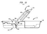
- FIG. 13is a cross-sectional view of the stand shown in FIG. 12 taken along line A-A with a syringe assembled therewith;
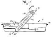
- FIG. 14is a cross-sectional view of the stand shown in FIG. 12 taken along line B-B with a syringe, show in full sectional view, assembled therewith.
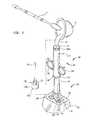
- stand 10includes base portion 12 and top portion 14 .
- base 12does not require the use of any particular shape; however, base 12 should be structured to allow stand 10 to stably rest on a surface while in use.
- base 12can include a flat bottom portion 24 that is sufficiently wide enough to stably support syringe 30 during use.
- the flat bottom portion 24includes a flange 26 formed thereon.
- stand 10includes a package portion 70 that is preferably attached to base 12 . The package portion is useful for transporting and storing with syringe 30 , other tools or materials that are used in connection with syringe 30 .
- Stand 10is preferably made of plastic or any other suitable polymeric material such as polyethylene, and is preferably transparent.
- the thickness and composition of the material used to form stand 10should result in stand 10 being flexible.
- stand 10is formed by vacuum molding or other similar methods.
- stand 10is in the form of a blister pack such that it is formed from a thin, unitary piece of material that is molded to form the three-dimensional shape of stand 10 . This results in the stand 10 having a generally hollow inside portion (not shown).
- the material comprising stand 10should be thin enough to be flexible, but should be thick enough to be rigid such that it securely engages an appropriate feature of syringe 30 .
- Such a featurecan include barrel 32 , including any section thereof, or handles 50 , which are affixed to barrel 32 , but will preferably include nozzle 34 or proximal end 46 of plunger 44 .
- top portion 14 of stand 10is generally planar, except for aperture 16 formed therein.
- Aperture 16is structured and dimensioned to receive nozzle 34 of syringe 30 and can take a variety of shapes from circular to more complicated geometric designs. Generally, the dimension of aperture 16 should be such that it forms a pressure fit with nozzle 34 . For example, if nozzle 34 is substantially circular, aperture 16 can also be circular, having a diameter that is slightly less than that of nozzle 34 .
- the pressure fit formed between aperture 16 and nozzle 34should be sufficient to hold syringe 30 in an upright position when inserted in the stand.
- uprightis not limited to a completely vertical position (i.e., orthogonal to the surface on which stand 10 rests), but includes any orientation of syringe 30 wherein the opening through which the injectable material 88 is deposited into syringe 30 has an elevation that is vertically greater than that of the portion of syringe 30 which is inserted into the stand.
- Syringe 30can vary in size, depending on the application for which it is designed. Accordingly, aperture 16 will be dimensioned to fit a specific one of these various sizes. Ideally, syringe 30 will be packaged with stand 10 having an aperture 16 of an appropriate size to match that of nozzle 34 of syringe 30 . In a preferred embodiment, stand 10 is integrally formed with part of packaging 70 for syringe 30 .
- aperture 16has a bottom portion 22 that is positioned below top portion 14 at a distance such that shoulder section 38 of syringe 30 contacts top portion 14 and port 36 of nozzle 34 contacts bottom surface 22 of aperture 16 .
- a preferred embodiment of stand 10includes an aperture 16 having a shape that forms a series of projections 18 and accompanying recesses 20 .
- Any number of projections 18 and recesses 20can be used in the shape of aperture 16 , but preferably aperture 16 has at least three projections 18 and three recesses 20 .
- projections 18make contact with nozzle 34
- recesses 20are spaced apart therefrom.
- Projections 18are dimensioned to form a pressure fit with nozzle 34 .
- aperture 16has one projection 18 and one recess 20 , wherein nozzle 34 makes contact with a portion of recess 20 and with projection 18 .
- aperture 16is tapered, having a greater diameter toward the top portion 14 than toward the bottom 22 thereof.
- aperture 116is adapted to engage the proximal end 146 of plunger 144 .
- Plunger 144is of the type normally used in connection with a syringe. Specifically, plunger 144 is cylindrical in shape and is dimensioned to fit within the open end 140 of syringe 130 . Plunger 144 typically includes a tip (such as tip 48 shown in FIG. 4 ) which effects a seal between the inside of the barrel 132 of syringe 130 . The seal between the tip and barrel 132 is preferably impervious to fluid.
- the seal formed between the tip and barrel 132provides a friction force therebetween, which is sufficient to support the weight of barrel 132 when syringe 130 is secured in stand 110 .
- Such an arrangementeliminates the need present in other embodiments of stand 10 to structure aperture 16 to form a seal over the open end of nozzle 34 .
- the present embodimentfacilitates the removal of air pockets or bubbles that may be present in the injectable composition when it is transferred into syringe 130 .
- Proximal end 146 of plunger 144varies in shape among differing plunger designs, but will typically form a surface that is larger in area than plunger rod 145 .
- Aperture 116can be adapted to receive any feature which may be present on the proximal end 146 of plunger 144 .
- Aperture 116can be of any shape that will provide a pressure-fit sufficient to engage proximal end 146 to maintain the syringe in an upright position.
- aperture 116will have a profile along a horizontal plane therethrough that substantially matches the profile of proximal end 146 when intersected by the same plane.
- aperture 116is tapered such that it is wider near the top surface 114 than at the bottom 122 of the aperture 116 . This arrangement aids in inserting proximal end 146 into the aperture 116 .
- aperture 116includes a series of projections 118 and recesses 120 designed to contact proximal end 146 at a predetermined number of points. Although any number of projections 118 and recesses 120 may be employed in such a design, it is preferable that the aperture has four projections and four recesses. The overall size of aperture 116 , as well as the projections 118 and recesses 120 will vary in accordance with the shape of proximal end 146 in a manner that can be determined by those having reasonable skill in the art.
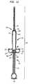
- Syringe 130 of the type depicted in FIG. 3is particularly advantageous for use with a stand of the present embodiment and, perhaps, for other purposes.
- This variation of syringe 130has a two-part barrel construction, wherein barrel 132 is divided into proximal and distal portions 132 a , 132 b .
- Distal portion 132 b of barrel 132includes nozzle 134
- proximal portion 132 aincludes open end 140 and handles 150 .
- Proximal and distal portions 132 a , 132 b of barrel 132are designed for mutual engagement therebetween and preferably include a mechanism, such as a thread-fit, pressure-fit or snap fit, to secure the engagement between the two portions 132 a , 132 b .
- this mechanismpreferably includes mating threaded sections 133 a , 133 b , one on each of proximal portion 132 a and distal portion 132 b .
- the male portion 133 a of the threaded section 133is included on proximal portion 132 a of barrel 132
- female threaded portion 133 bis included on distal portion 132 b.
- This variation of syringe 130operates with stand 110 by providing a sufficiently wide opening 152 to deposit the injectable substance 88 into barrel 132 .
- proximal end 146 of plunger 144is inserted into aperture 116 of stand 110 , the distal portion 132 b of barrel 132 having been removed from the proximal portion 132 a .
- the tip of plunger 144is positioned sufficiently near the opening end 140 to allow syringe 130 to contain the desired amount of injectable substance 88 .
- the position of the tip within barrel 132is maintained by the friction between the tip and the interior of barrel 132 .
- the injectable substance 88is then prepared and deposited into the syringe through opening 152 .
- distal portion 132 b of barrel 132is re-assembled onto proximal portion 132 a of barrel 132 and syringe 130 is used in a typical fashion.
- proximal portion 132 a of barrel 132represents a greater portion of the entire barrel 132 than does distal portion 132 b ; but the barrel may be divided anywhere, depending on the purpose for which it is divided.
- the distal portion 132 bneed only be large enough as necessary to support nozzle 134 .
- This arrangementallows the interior of barrel 132 to be filled with as much of injectable substance 88 as possible before distal portion 132 b is re-assembled onto proximal portion 132 b .
- This arrangementis also advantageous for a kit having several choices of different nozzle assemblies that can be fit onto the proximal portion 132 a .
- such different nozzlescould be differently sized for different applications and a surgeon could choose a nozzle intraoperatively.
- opening 152abuts the inside surface of shoulder section 138 of distal portion 132 b when distal portion 132 b is engaged onto proximal portion 132 a.
- a recesscan be provided in the package which is larger than the feature of the syringe to be held therein (whether it be the nozzle or the proximal plunger portion), as well as deeper so that the syringe can be placed in such large and deep recess and so held in an upright position.
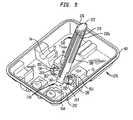
- stand 10is formed as part of package 70 .
- package 70is designed to carry syringe 30 .
- package 70is one for a bone cement preparation kit.
- a kit according to this embodiment of the present inventionis generally in the form of a blister pack in which stand 10 is connected to package 70 at base 12 of stand 10 .
- Stand 10can be located anywhere in package 70 but, for purposes of stability, is preferably located near the center of package 70 .
- Package 70has various compartments for the elements contained therein. Such elements include syringe 30 which is held within a snap channel 72 specifically designed to securely hold syringe 30 in a horizontal position within package 70 .
- package 70also contains a compartment 74 designed to hold wet ingredient container 60 , which is usually in the form of a second syringe.
- An additional compartment 76is also preferably formed within package 70 and is dimensioned to securely hold a mixing spatula 62 therein.
- a fourth compartment 78is preferably formed within package 70 such that it can hold a cannula 64 that is specifically adapted for attachment to nozzle 34 of syringe 30 .
- mixing bowl 86is preferably supplied with package 70 .
- Mixing bowl 86contains a dry ingredient which is part of a bone cement composition.
- the wet ingredientis added to the dry ingredient in mixing bowl 86 , and the two ingredients are mixed together using spatula 62 to form a bone cement composition.
- package 70is placed into an outer tray 82 , which further helps to maintain the sterility of package 70 and the components held therein.
- a lidis then affixed to flange 84 of outer tray 82 to seal the components therein.
- the lidis made from TyvekTM, or another material which serves the purpose of sealing the contents of package 70 so as to preserve the sterility and integrity of the ingredients.
- mixing bowl 86it is possible to supply mixing bowl 86 within package 70 , having a corresponding compartment (not shown) formed therein, it is preferred that mixing bowl 86 is not included within package 70 , but is otherwise supplied with package 70 . Such an arrangement is shown in FIG.
- mixing bowl 86having lid 87 affixed thereto, rests or is otherwise secured within a compartment formed in inner blister 71 .
- Inner blister 71is then placed in outer blister 83 and an outer lid (not shown) is affixed thereto.
- the assembled outer blister 83 and outer tray 82are each sealed in their own outer pouch (not shown), which is preferably made of foil.
- Outer tray 82 and outer blister 83are then inserted into a carton (not shown), which is typically made from cardboard or other similar material.
- a desiccantis preferably included with mixing bowl 86 , or any other container used to hold a dry ingredient of a bone cement composition used in connection with stand 10 .
- the inclusion of a desiccantensures that the storage environment of the powder is kept dry in order to prevent “aging” of the powder in the presence of free moisture, which would render the powder unusable.
- desiccantis included with mixing bowl 86 by placing a desiccant pack in outer blister 83 between outer blister 83 and inner blister 71 .
- a desiccant pack containing about 10 grams of color indicating silica gelis supplied, however other available desiccants include those made of clay and calcium chloride.
- the appropriate amount of desiccantvaries with the particular application, the determination of which is generally understood in the art.
- package 70includes an outer flange 80 to which a lid (not shown) is affixed.
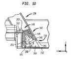
- stand 210includes a protrusion 260 extending generally upwardly from base 212 .
- Protrusion 260is structured to fit within the open end 140 of proximal end 142 of barrel 132 of syringe 130 (shown generally in FIG. 3 ).
- stand 210is shown in FIGS. 7-9 as including a package portion 270 integrally formed with base 212 , stand 210 may be formed so as to stand alone on a surface, supported by base 212 , as shown and described with respect to previous embodiments discussed herein.
- Protrusion 260may be shaped so as to form a pressure-fit within proximal end 142 of barrel 132 .
- protrusion 260may be sufficiently sized and shaped so as to alone support syringe 130 in an upright position. Alternatively, as discussed below, protrusion 260 may act together with another structure of the tray and/or the syringe to support the syringe.
- the shape of the protrusion 260 in a preferred embodimentsubstantially matches the shape of at least a portion of the interior of barrel 132 .
- the syringe 130 depicted in the Figureshas a substantially cylindrically-shaped barrel 132
- protrusion 260has a substantially cylindrical shape so as to match that of barrel 132 .
- any shapemay be used for protrusion which accomplishes the desired fit between protrusion 260 and barrel 132 .
- a partially matching shape for protrusion 260is contemplated.
- stand 210can further include a support that contacts a portion of barrel 132 located distally of proximal end 142 .
- the supportis in the form of a pair of pedestals 262 , 264 that fit within handles 150 of syringe 130 (as best shown in FIG. 9 ).
- Pedestals 262 , 264each include a top surface 263 , 265 , which preferably are shaped to contact the uppermost portion 151 of the respective handles 150 such that handles 150 are supported by pedestals 262 , 264 .
- top surfaces 263 , 265are contoured to match the shape of handles 150 of a syringe 130 provided therewith.
- top surfaces 263 , 265are concave so as to match the particular shape of the handles 150 included on syringe 130 shown in FIGS. 9 and 10 .
- stand 210preferably holds syringe 130 at an oblique angle relative to base 212 . This may be accomplished by orienting protrusion 260 at an angle relative to base 212 that substantially matches the desired angle for syringe. Additionally, pedestals 262 , 264 may be positioned so as to support syringe 130 at the desired angle. The proper position of top surfaces 263 , 265 will depend on the location of handles 150 with respect to opening 140 , and in particular with respect to lip 141 formed on the outside edge of opening 140 , which may contact base 212 at a point along the intersection between base 212 and protrusion 260 .
- top surfaces 263 , and 265will be spaced apart from protrusion in a lateral direction X and a vertical direction Z, as shown in FIG. 10 .
- syringe 130is positioned at an angle ⁇ relative to base 212 of between 40 and 70 degrees. More preferably, the angle ⁇ between syringe 130 and base 212 is about 45 degrees.
- top surfaces 263 , 264may include a vertical surface, which may provide additional support for handles 150 , particularly when stand 210 is structured to hold syringe 130 in an angled position.
- Syringe 130may be particularly adapted for use with the stand of the present embodiment.
- syringe 130includes an opening 152 at distal portion 132 a of barrel 132 , which provides for access to barrel 132 through which a material 88 can be poured.
- a funnel 170can be adapted to be affixed to barrel 132 at the opening 152 .
- Funnel 170can include a threaded portion (not shown) that substantially matches that of threaded portion 133 a included on distal end 132 a of barrel 132 .
- Funnel 170can be of any suitable shape, but is preferably structured to provide an opening 172 having an area greater than open end 152 .
- funnel 170can be used to provide an upwardly-angled edge 176 that may aide in pouring material 88 into syringe 130 when it is in an angled position.
- plunger 144may include rod 145 that is removable from tip 148 .
- tip 148is assembled within barrel 132 when syringe 130 is held on stand 210 so that material 88 is prevented from escaping through proximal end 142 of barrel 132 when syringe 130 is in the upright position shown in FIGS. 7-9 wherein proximal end 142 is vertically below distal end 132 a .
- Tip 148is preferably located within barrel 132 at a position which maximizes the amount of material that can be held therein, while allowing protrusion 260 to extend into barrel 132 at an appropriate distance.
- protrusion 260may have a top surface 266 that contacts the proximal surface of the plunger tip 148 in order to help support tip 148 when material 88 is poured into syringe 130 .
- plunger rod 145can be assembled with tip 148 so that material 88 can be expelled from syringe 130 using plunger 144 .
- tipmay include, for example a threaded hole 149
- rod 145may include a substantially mating threaded post 147 so that rod may be threaded and unthreaded from tip 148 as needed.
- Package portion 270 used with a syringe 130 of this typemay include an additional chamber 75 that can be used to hold plunger rod 145 during transportation and storage of syringe 130 .
- syringe 130may include a plurality of ribs 180 spaced around and projecting from the outside surface 131 of barrel 132 .
- ribs 180extend along barrel 130 in a proximal-distal direction, as shown; however, other arrangements are possible. Ribs 180 help space apart the hand of a user from barrel 132 , should the user need to hold syringe 130 by barrel 132 during use. This is intended to reduce the amount of heat transferred from the hand of the user to material 88 contained within barrel 132 , and is particularly advantageous when material 88 is a heat-activated composition.
- between four and eight ribs 180are included around outside surface 131 of barrel 132 .
- Funnel 170 and/or nozzle 134may also include ribs 180 which may additionally provide grip when attaching or removing these features from barrel 132 and may differentiate the features from barrel 132 .
- FIGS. 12-14A further alternative embodiment of stand 310 for use with syringe 130 is shown in FIGS. 12-14 .
- Stand 310is similar to previous embodiments, except in the mechanism used to hold syringe 130 .
- stand 310uses a clip 360 in order to hold syringe 130 in the desired position.
- the exemplary embodiment of clip 360 shown in FIGS. 12-14is structured so as to form a pressure fit at least on a portion of either or both handles 150 which project from the sides of barrel 132 of syringe 130 .
- Other arrangements, however,are possible where clip 360 forms a pressure fit with other features or areas of syringe 130 .
- a “clip”is characterized by a structure that forms a pressure fit with an object or a portion of an object inserted therein in order to retain the object, wherein the pressure fit is achieved in a preferred embodiment, in part, through deformation of the structure.
- a structuremay further act to retain an object by partially deforming into a maximum deformed position at an instance during insertion of the retained object into the clip and then by partially returning from the maximum deformed state when the object is fully inserted therein.
- clip 360includes tab 362 and surface 364 , wherein tab 362 contacts the proximal-most portion of handle 150 .
- Surface 364opposes the inside surface of tab 362 and is arranged to support handle 150 along a side thereof in order to maintain a position of syringe 130 relative to stand 310 .
- surface 364is positioned relative to base 312 of stand 310 at an angle of approximately 45 degrees, which acts to hold syringe 130 at an angle of approximately 45 degrees relative to base 312 .
- Other angles for the position of surface 364 relative to base 312are possible, including anywhere from 90 degrees to about 30 degrees, preferably between 30 degrees and 60 degrees, and more preferably about 45 degrees.
- Indentation 366may be formed in stand 310 so as to act with clip 360 in retaining syringe 130 . As shown in FIG. 14 , a portion of indentation 366 contacts a portion of barrel 132 of syringe 130 , particularly at the proximal end of barrel 132 . This contact between indentation 366 and the proximal end of barrel 132 furthers the retention of syringe 130 to stand 310 by providing an additional point of contact to make the angular position of syringe more stable and by furthering the pressure fit of clip 360 to syringe 130 . The pressure fit is furthered, in the exemplary embodiment depicted in FIGS.
- protrusion 362provides the fulcrum for such leverage by providing a force to handle opposed to the force applied by surface 364 and indentation 366 .
- Surface 364can include a bump 368 , or other similar protrusion, extending therefrom.
- Bump 368is positioned so as to abut the surface of handle 150 that faces away from clip. As shown in FIGS. 12-13 , bump 368 abuts the distal-most surface of handle 150 and acts to partially prevent upward displacement of syringe 130 relative to stand 310 .
- stand 310preferably includes a pair of clips 360 , each being sized and positioned to engage a respective one of the pair of handles 150 which project outwardly from barrel 132 .
- the clips 360are positioned such that one is on each side of indentation 366 .
- a further aspect of the present inventionincludes a method for using stand as discussed above.
- stand 10 according to FIG. 2is provided as well as a syringe 30 .
- Stand 10is placed on a surface and syringe 30 is inserted into the stand.
- Stand 10has an aperture 16 that secures syringe 10 at nozzle 34 .
- Stand 10is designed to maintain syringe 30 in an upright position.
- the injectable substance 88is then deposited into the barrel 32 of syringe 30 .
- This materialcan be anything that is intended to be injected using syringe 30 but is preferably an injectable bone cement composition.
- Plunger 44is then inserted into barrel 32 of syringe 30 .
- Syringe 30is then removed from stand 10 .
- Stand 10includes a package portion 70 that includes compartment 72 for holding syringe 30 in a horizontal position therein during shipment or storage of stand 10 .
- package 70contains additional compartments used to store other devices or containers used in connection with stand 10 .
- outer tray 82has a lid (not shown) affixed thereto at flange 84 thereof. Lid is first removed from flange 84 and syringe 30 is removed from snap channel 72 , where it is contained. Plunger 44 is then removed from barrel 32 of syringe 30 by pulling plunger 44 out of said barrel 32 .
- Plunger 44is then set aside and syringe 30 is inserted into stand 10 in an upright position.
- nozzle 34 of syringe 30is inserted into aperture 16 of stand 10 .
- proximal end 146 of plunger 144is inserted into aperture 116 , which is appropriately formed therein.
- spatula 62is included in compartment 76 , which is preferably in the form of a snap-channel, within package 70 , and a container 60 for a liquid ingredient is held compartment 74 within package 70 . Both spatula 62 and container 60 are removed from package 70 and set aside.
- mixing bowl 86which contains a dry ingredient for a bone cement composition, is provided.
- Mixing bowl 86contains lid 87 affixed thereto, which is removed and discarded.
- the liquid ingredient in container 60is then deposited into mixing bowl 86 , and spatula 62 is used to thoroughly mix the wet ingredient with the dry ingredient to form a bone cement composition.
- mixing bowl 86is placed near an appropriate opening of syringe 30 , which will vary by application. If the nozzle 34 of syringe is inserted into aperture 16 , this opening will be open end 40 . Alternatively, if proximal end 146 of plunger 144 is inserted into aperture 116 , then the mixing bowl will be placed near opening 152 . Mixing bowl 86 is then tilted such that injectable substance 88 flows into barrel 32 of syringe 30 . If necessary, spatula 62 is used to aid in this process.
- plunger 44is reinserted into barrel 32 .
- plunger 44is advanced into the barrel 32 until tip 48 of the plunger 44 contacts the upper surface of the injectable substance 88 contained within syringe 30 .
- plunger 44may include an air-release port (not shown) that begins at a small orifice in tip 48 of plunger 44 and continues to proximal end 46 of the plunger 44 . This arrangement allows for any air in the syringe 30 above the surface of the injectable substance 88 to escape from inside syringe 30 without forcing the injectable substance 88 from syringe 30 through nozzle 34 .
- package 70further contains a cannula 64 held compartment 78 .
- cannula 64is removed from compartment 78 and then syringe 30 is removed from stand 10 .
- Cannula 64is then assembled onto nozzle 34 of syringe 30 .
- Incorporation of male and female thread portionsaids in such assembly. This method allows for fast, efficient loading of a syringe 30 with an injectable substance 88 that is preferably a rapid-setting bone cement composition. It also allows for more accurate filling of syringe 30 by a single user.
- a stand according to the present inventionis preferable regardless of whether or not the bone cement composition is heat-activated, because any fast setting bone cement composition must be quickly mixed and deposited into syringe 30 for injecting into a host before the bone cement composition sets. Furthermore, because bone cements and other additional materials are loaded from the top of the syringe, difficulty may be experienced by a single person attempting to fill syringe 30 .
- syringe 30can be of any type related to any field of use.
- syringe 30relates to medical devices, and more particularly, to devices used in orthopedics, specifically delivery of rapid setting bone cement compositions.
- variations of syringe 30within other fields can be used in conjunction with the present invention.
Landscapes
- Health & Medical Sciences (AREA)
- Life Sciences & Earth Sciences (AREA)
- Animal Behavior & Ethology (AREA)
- Veterinary Medicine (AREA)
- Biomedical Technology (AREA)
- Heart & Thoracic Surgery (AREA)
- Public Health (AREA)
- Engineering & Computer Science (AREA)
- General Health & Medical Sciences (AREA)
- Surgery (AREA)
- Vascular Medicine (AREA)
- Hematology (AREA)
- Anesthesiology (AREA)
- Nuclear Medicine, Radiotherapy & Molecular Imaging (AREA)
- Medical Informatics (AREA)
- Molecular Biology (AREA)
- Orthopedic Medicine & Surgery (AREA)
- Infusion, Injection, And Reservoir Apparatuses (AREA)
- Medical Preparation Storing Or Oral Administration Devices (AREA)
Abstract
Description
Claims (18)
Priority Applications (1)
| Application Number | Priority Date | Filing Date | Title |
|---|---|---|---|
| US12/887,663US8303599B2 (en) | 2006-01-30 | 2010-09-22 | Syringe |
Applications Claiming Priority (4)
| Application Number | Priority Date | Filing Date | Title |
|---|---|---|---|
| US11/343,183US20070185495A1 (en) | 2006-01-30 | 2006-01-30 | Plug-in syringe stand |
| US11/522,224US20080125722A1 (en) | 2006-09-15 | 2006-09-15 | Syringe and stand |
| US11/641,618US8403936B2 (en) | 2006-01-30 | 2006-12-19 | Syringe and stand |
| US12/887,663US8303599B2 (en) | 2006-01-30 | 2010-09-22 | Syringe |
Related Parent Applications (1)
| Application Number | Title | Priority Date | Filing Date |
|---|---|---|---|
| US11/641,618ContinuationUS8403936B2 (en) | 2006-01-30 | 2006-12-19 | Syringe and stand |
Publications (2)
| Publication Number | Publication Date |
|---|---|
| US20110015640A1 US20110015640A1 (en) | 2011-01-20 |
| US8303599B2true US8303599B2 (en) | 2012-11-06 |
Family
ID=38792267
Family Applications (4)
| Application Number | Title | Priority Date | Filing Date |
|---|---|---|---|
| US11/343,183AbandonedUS20070185495A1 (en) | 2006-01-30 | 2006-01-30 | Plug-in syringe stand |
| US11/641,618Active2029-07-15US8403936B2 (en) | 2006-01-30 | 2006-12-19 | Syringe and stand |
| US12/887,663ActiveUS8303599B2 (en) | 2006-01-30 | 2010-09-22 | Syringe |
| US13/793,094Active2026-06-15US8945134B2 (en) | 2006-01-30 | 2013-03-11 | Syringe and stand |
Family Applications Before (2)
| Application Number | Title | Priority Date | Filing Date |
|---|---|---|---|
| US11/343,183AbandonedUS20070185495A1 (en) | 2006-01-30 | 2006-01-30 | Plug-in syringe stand |
| US11/641,618Active2029-07-15US8403936B2 (en) | 2006-01-30 | 2006-12-19 | Syringe and stand |
Family Applications After (1)
| Application Number | Title | Priority Date | Filing Date |
|---|---|---|---|
| US13/793,094Active2026-06-15US8945134B2 (en) | 2006-01-30 | 2013-03-11 | Syringe and stand |
Country Status (6)
| Country | Link |
|---|---|
| US (4) | US20070185495A1 (en) |
| EP (1) | EP1813299A3 (en) |
| JP (1) | JP2007216009A (en) |
| CN (1) | CN101011287A (en) |
| AU (2) | AU2007200378B2 (en) |
| CA (1) | CA2576533A1 (en) |
Cited By (29)
| Publication number | Priority date | Publication date | Assignee | Title |
|---|---|---|---|---|
| US20080287798A1 (en)* | 2007-05-15 | 2008-11-20 | General Electric Company | Packaging and fluid filling of ultrasound imaging catheters |
| US20140261855A1 (en)* | 2013-03-14 | 2014-09-18 | Warsaw Orthopedic, Inc. | Filling systems for bone delivery devices |
| US9114201B2 (en) | 2011-11-10 | 2015-08-25 | Panasonic Healthcare Holdings Co., Ltd. | Storage case for pharmaceutical syringe unit |
| US9333289B1 (en) | 2015-01-16 | 2016-05-10 | Plas-Tech Engineering, Inc. | Tamper evident closure container |
| USD775328S1 (en) | 2013-12-02 | 2016-12-27 | Bce Pharma Inc. | Needle protector support |
| USD782331S1 (en)* | 2015-07-30 | 2017-03-28 | S-Printing Solution Co., Ltd | Packaging for a printer component |
| USD782332S1 (en)* | 2015-07-30 | 2017-03-28 | S-Printing Solution Co., Ltd | Packaging for a printer component |
| USD782330S1 (en)* | 2015-07-30 | 2017-03-28 | S-Printing Solution Co., Ltd. | Packaging for a printer component |
| US20170143893A1 (en)* | 2014-08-06 | 2017-05-25 | Terumo Kabushiki Kaisha | Packaging body and package assembly |
| US9827349B1 (en)* | 2013-11-26 | 2017-11-28 | Abyrx Inc. | Settable surgical implants and their packaging |
| US9828157B2 (en)* | 2013-03-09 | 2017-11-28 | Rose Plastic Ag | Methods of packaging and packaging for sharp-edged tools |
| US9931330B2 (en) | 2012-11-08 | 2018-04-03 | Clearside Biomedical, Inc. | Methods and devices for the treatment of ocular diseases in human subjects |
| US10390901B2 (en) | 2016-02-10 | 2019-08-27 | Clearside Biomedical, Inc. | Ocular injection kit, packaging, and methods of use |
| US10722384B2 (en)* | 2017-03-01 | 2020-07-28 | Nordson Corporation | Medical material mixer and transfer apparatus and method for using the same |
| US10973681B2 (en) | 2016-08-12 | 2021-04-13 | Clearside Biomedical, Inc. | Devices and methods for adjusting the insertion depth of a needle for medicament delivery |
| US11197733B2 (en) | 2017-04-12 | 2021-12-14 | Mako Surgical Corp. | Packaging systems and methods for mounting a tool on a surgical device |
| US11351299B2 (en)* | 2019-03-15 | 2022-06-07 | Chiesi Farmaceutici S.P.A. | System comprising a pre-fillable syringe and a package for the pre-fillable syringe |
| US11369733B2 (en)* | 2019-03-15 | 2022-06-28 | Chiesi Farmaceutici S.P.A. | System comprising a pre-fillable syringe and a package for the pre-fillable syringe |
| US11395711B2 (en) | 2019-06-05 | 2022-07-26 | Stryker European Operations Limited | Packaging systems and methods for mounting a tool on a surgical device using the same |
| US11559428B2 (en) | 2013-05-03 | 2023-01-24 | Clearside Biomedical, Inc. | Apparatus and methods for ocular injection |
| US11596545B2 (en) | 2016-05-02 | 2023-03-07 | Clearside Biomedical, Inc. | Systems and methods for ocular drug delivery |
| US11690680B2 (en) | 2019-03-19 | 2023-07-04 | Mako Surgical Corp. | Trackable protective packaging for tools and methods for calibrating tool installation using the same |
| US11737802B1 (en)* | 2022-07-25 | 2023-08-29 | Zavation Medical Products, Llc | Bone cement mixer |
| US11752101B2 (en) | 2006-02-22 | 2023-09-12 | Clearside Biomedical, Inc. | Ocular injector and methods for accessing suprachoroidal space of the eye |
| USD1035436S1 (en) | 2022-08-26 | 2024-07-16 | Regeneron Pharmaceuticals, Inc. | Packaging |
| USD1042107S1 (en) | 2022-08-26 | 2024-09-17 | Regeneron Pharmaceuticals, Inc. | Packaging |
| US12090088B2 (en) | 2010-10-15 | 2024-09-17 | Clearside Biomedical, Inc. | Device for ocular access |
| US12090294B2 (en) | 2017-05-02 | 2024-09-17 | Georgia Tech Research Corporation | Targeted drug delivery methods using a microneedle |
| USD1047700S1 (en) | 2022-08-26 | 2024-10-22 | Regeneron Pharmaceuticals, Inc. | Packaging |
Families Citing this family (31)
| Publication number | Priority date | Publication date | Assignee | Title |
|---|---|---|---|---|
| AU2004100000A4 (en) | 2004-01-02 | 2004-02-12 | Sands Innovations Pty Ltd | Dispensing stirring implement |
| USD579561S1 (en)* | 2004-01-30 | 2008-10-28 | Physician Industries, Inc. | Portion of a syringe |
| US8192698B2 (en)* | 2006-01-27 | 2012-06-05 | Parker-Hannifin Corporation | Sampling probe, gripper and interface for laboratory sample management systems |
| US20070185495A1 (en) | 2006-01-30 | 2007-08-09 | Howmedica International S. De R. L. | Plug-in syringe stand |
| CN101600633A (en)* | 2007-01-31 | 2009-12-09 | 桑德斯创新有限公司 | Dispensing utensil and manufacture method thereof |
| CA2928681C (en)* | 2007-08-29 | 2018-03-27 | Etex Corporation | Bone cement mixing and delivery system and methods of use thereof |
| GB0723307D0 (en)* | 2007-11-28 | 2008-01-09 | Frontier Plastics Ltd | Mixing pan and mat |
| US8523016B2 (en) | 2008-12-09 | 2013-09-03 | Sands Innovations Pty Ltd. | Dispensing container |
| US8034034B2 (en)* | 2009-01-12 | 2011-10-11 | Howmedica Osteonics Corp. | Syringe and method of use |
| US8511500B2 (en) | 2010-06-07 | 2013-08-20 | Sands Innovations Pty. Ltd. | Dispensing container |
| US8485360B2 (en) | 2011-03-04 | 2013-07-16 | Sands Innovations Pty, Ltd. | Fracturable container |
| WO2013141187A1 (en)* | 2012-03-22 | 2013-09-26 | テルモ株式会社 | Drug injection device |
| US9889248B2 (en)* | 2012-05-21 | 2018-02-13 | Baxalta GmbH | Syringe storage tray |
| US9943641B2 (en)* | 2013-03-14 | 2018-04-17 | Becton, Dickinson And Company | Package for medical product |
| EP3003454B1 (en) | 2013-06-03 | 2020-01-08 | Clearside Biomedical, Inc. | Apparatus for drug delivery using multiple reservoirs |
| US9504507B2 (en)* | 2013-07-05 | 2016-11-29 | Tecres S.P.A. | Injector device for introducing biocompatible material into deep anatomical areas |
| US9532847B2 (en)* | 2013-07-16 | 2017-01-03 | Gt Urological, Llc | Medical device package |
| US20150223918A1 (en)* | 2014-02-11 | 2015-08-13 | Anoop S. Bawa | Dental paste dispenser and method of use |
| EP3142590B1 (en)* | 2014-05-16 | 2020-05-13 | Smith & Nephew plc | Reduced pressure wound therapy kit and packaging |
| WO2016113207A1 (en)* | 2015-01-12 | 2016-07-21 | Sanofi-Aventis Deutschland Gmbh | Packaging for pre-filled drug cartridges with peg for pushing cartridge stopper for priming purposes |
| WO2017220795A1 (en)* | 2016-06-24 | 2017-12-28 | Teva Pharmaceuticals International Gmbh | Medical device packaging |
| AR108886A1 (en) | 2016-06-27 | 2018-10-03 | Baxalta Inc | SYRINGE STABILIZER |
| WO2018129082A1 (en)* | 2017-01-03 | 2018-07-12 | Loma Linda University | Syringe steadying device, kit, and associated methods |
| US10709576B2 (en) | 2017-04-28 | 2020-07-14 | Warsaw Orthopedic, Inc. | Bone material dispensing apparatus and methods |
| DE102019002962A1 (en)* | 2019-04-30 | 2020-11-05 | Anton Härle | Medical transfer system |
| US11583403B2 (en) | 2019-11-15 | 2023-02-21 | Warsaw Orthopedic, Inc. | Bone implant holding and shaping tray |
| JP2023551606A (en)* | 2020-12-01 | 2023-12-08 | 武田薬品工業株式会社 | Fluid delivery system containers and methods of use |
| US11969194B2 (en) | 2021-07-19 | 2024-04-30 | Warsaw Orthopedic, Inc. | Bone material dispensing system and methods of use |
| US12329430B2 (en) | 2021-07-19 | 2025-06-17 | Warsaw Orthopedic, Inc. | Bone material dispensing system and methods of use |
| US12144744B2 (en) | 2021-07-19 | 2024-11-19 | Warsaw Orthopedic, Inc. | Bone material dispensing device with distal frame |
| WO2025006533A1 (en)* | 2023-06-26 | 2025-01-02 | Life Technologies Corporation | Assembly and system for controlled dispensing of fluid |
Citations (97)
| Publication number | Priority date | Publication date | Assignee | Title |
|---|---|---|---|---|
| US3083821A (en) | 1961-05-15 | 1963-04-02 | Kenneth W Woodson | Package sealing |
| US3618751A (en) | 1970-01-15 | 1971-11-09 | Joseph Nichlos | Crushing and dispensing container for administering pills |
| US3756571A (en) | 1971-10-29 | 1973-09-04 | R Winberg | Mixing capsule in particular for dental preparation |
| US4008803A (en) | 1972-11-08 | 1977-02-22 | Smith F Charles | Package for two reactive ingredients of a desired mix in a single pack |
| US4135868A (en) | 1977-04-05 | 1979-01-23 | Herbert Schainholz | Supports for instrument sterilization |
| US4277184A (en) | 1979-08-14 | 1981-07-07 | Alan Solomon | Disposable orthopedic implement and method |
| US4294349A (en) | 1978-07-21 | 1981-10-13 | Den-Mat, Inc. | Kit for repair of porcelain dental prostheses |
| US4299238A (en) | 1980-06-24 | 1981-11-10 | Baidwan Balinderjeet S | Vented piston and push-rod subassembly for use in a syringe barrel |
| US4341302A (en) | 1980-10-15 | 1982-07-27 | United Fillers Pty. Ltd. | Storing and mixing apparatus |
| US4364473A (en) | 1978-10-11 | 1982-12-21 | Bonyf Ag | Outfit for repair of split dental prosthesis |
| US4420085A (en) | 1982-01-15 | 1983-12-13 | The Kendall Company | Stand up organizer |
| USD280290S (en) | 1983-03-04 | 1985-08-27 | Felt Products Mfg. Co. | Combined packaging and mixing container |
| US4632672A (en) | 1985-10-07 | 1986-12-30 | Minnesota Mining And Manufacturing Company | Self venting syringe plunger |
| US4671263A (en) | 1984-07-11 | 1987-06-09 | Klaus Draenert | Device and process for mixing and applying bone cement |
| US4673085A (en) | 1984-12-27 | 1987-06-16 | Legrand | Package with peel-off film closure |
| US4697703A (en) | 1986-07-02 | 1987-10-06 | Malcolm Will | Joint prosthesis package |
| US4701165A (en)* | 1986-03-26 | 1987-10-20 | Abbott Interfast Corp. | Reusable syringes |
| US4820306A (en) | 1981-06-22 | 1989-04-11 | Sterling Drug Inc. | Method for augmentation of the alveolar ridge |
| US4832692A (en) | 1986-10-14 | 1989-05-23 | Cordis Corporation | Inflation syringe assembly for percutaneous transluminal angioplasty |
| US4838866A (en) | 1986-10-03 | 1989-06-13 | Marshall Sr William M | Liquid pump air release system |
| US4844251A (en) | 1986-08-12 | 1989-07-04 | L'oreal | Container means for separately storing at least two products to be brought into contact at the time of use |
| US4844249A (en) | 1988-06-03 | 1989-07-04 | Maurice Coulombe | Medical supplies container |
| US4865591A (en) | 1987-06-12 | 1989-09-12 | Hypoguard (Uk) Limited | Measured dose dispensing device |
| US4880610A (en) | 1988-04-20 | 1989-11-14 | Norian Corporation | In situ calcium phosphate minerals--method and composition |
| US4966601A (en) | 1986-03-21 | 1990-10-30 | Klaus Draenert | Evacuatable bone cement syringe |
| US4973168A (en) | 1989-01-13 | 1990-11-27 | Chan Kwan Ho | Vacuum mixing/bone cement cartridge and kit |
| US5007535A (en) | 1988-09-26 | 1991-04-16 | Hammerlit Gmbh | Syringe tray |
| US5047031A (en) | 1988-04-20 | 1991-09-10 | Norian Corporation | In situ calcium phosphate minerals method |
| US5102083A (en)* | 1990-05-09 | 1992-04-07 | Unique Barrier Products Inc. | Disposable syringe needle and scalpel holder |
| US5121779A (en)* | 1990-12-31 | 1992-06-16 | John Green | Funnel |
| US5129905A (en) | 1988-04-20 | 1992-07-14 | Norian Corporation | Methods for in situ prepared calcium phosphate minerals |
| US5178845A (en) | 1988-04-20 | 1993-01-12 | Norian Corporation | Intimate mixture of calcium and phosphate sources as precursor to hydroxyapatite |
| US5193672A (en)* | 1992-01-28 | 1993-03-16 | Depuy Inc. | Surgical instrument case |
| US5203459A (en) | 1991-05-14 | 1993-04-20 | Wade Leslie C | Prepackaged oral medication serving apparatus and method |
| US5238003A (en) | 1992-02-07 | 1993-08-24 | Baidwan Balinderjeet S | Plunger tip for blood gas syringe |
| US5240415A (en) | 1990-06-07 | 1993-08-31 | Haynie Michel B | Dental bleach system having separately compartmented fumed silica and hydrogen peroxide and method of using |
| US5265724A (en) | 1992-05-06 | 1993-11-30 | Dondlinger Steven C | Medical needle disposal package |
| US5333737A (en) | 1992-08-19 | 1994-08-02 | Power Poxy Adhesives, Inc. | Packaging system for two part epoxy adhesives and the like |
| US5334173A (en) | 1993-04-01 | 1994-08-02 | Leonard Bloom | Stabilizing foot means for cap of needle assembly and method thereof |
| US5462356A (en) | 1994-06-01 | 1995-10-31 | Murray; William M. | Bone and dental cement method and preform |
| US5514137A (en) | 1993-12-06 | 1996-05-07 | Coutts; Richard D. | Fixation of orthopedic devices |
| US5569442A (en) | 1994-11-04 | 1996-10-29 | Norian Corporation | Reactive tricalcium phosphate compositions and uses |
| US5586821A (en) | 1995-10-10 | 1996-12-24 | Zimmer, Inc. | Bone cement preparation kit |
| US5697981A (en) | 1994-08-23 | 1997-12-16 | Norian Corporation | Method for repairing bone |
| US5735825A (en) | 1996-03-22 | 1998-04-07 | Merit Medical Systems, Inc. | Syringe plunger tip |
| US5782971A (en) | 1991-06-28 | 1998-07-21 | Norian Corporation | Calcium phosphate cements comprising amorophous calcium phosphate |
| US5794904A (en) | 1994-08-11 | 1998-08-18 | Hackley; Carl L. | Holder for inverted bottles |
| US5823363A (en) | 1996-10-18 | 1998-10-20 | Cassel; Douglas | Medical syringe holding/transport apparatus |
| US5842785A (en) | 1994-02-22 | 1998-12-01 | Summit Medical Ltd. | Orthopedic bone cement mixing device with syringe dispenser |
| US5865803A (en) | 1997-05-19 | 1999-02-02 | Major; Miklos | Syringe device having a vented piston |
| US5900254A (en) | 1988-04-20 | 1999-05-04 | Norian Corporation | Carbonated hydroxyapatite compositions and uses |
| US5951160A (en) | 1997-11-20 | 1999-09-14 | Biomet, Inc. | Method and apparatus for packaging, mixing and delivering bone cement |
| US5968253A (en) | 1998-07-31 | 1999-10-19 | Norian Corporation | Calcium phosphate cements comprising antimicrobial agents |
| US5975295A (en) | 1997-10-30 | 1999-11-02 | Diamond; Richard B. | Apparatus and method for organizing and recapping medical needles and syringes |
| US5975305A (en) | 1998-06-25 | 1999-11-02 | Comar, Inc. | Unit dose spoon |
| US6002065A (en) | 1988-04-20 | 1999-12-14 | Norian Corporation | Kits for preparing calcium phosphate minerals |
| US6005162A (en) | 1988-04-20 | 1999-12-21 | Norian Corporation | Methods of repairing bone |
| USD422674S (en)* | 1999-06-10 | 2000-04-11 | Blitz U.S.A., Inc. | Funnel |
| US6083229A (en) | 1996-12-13 | 2000-07-04 | Norian Corporation | Methods and devices for the preparation, storage and administration of calcium phosphate cements |
| US6120481A (en)* | 1998-12-21 | 2000-09-19 | Becton, Dickinson And Company | Scale on a plastic syringe |
| JP2000325362A (en) | 1999-05-18 | 2000-11-28 | Shiyoufuu:Kk | Viscous material-filling syringe for dentistry |
| US6241734B1 (en) | 1998-08-14 | 2001-06-05 | Kyphon, Inc. | Systems and methods for placing materials into bone |
| US6257408B1 (en) | 1999-12-02 | 2001-07-10 | David Odierno | Needle sheathing and unsheathing safety device |
| US6273916B1 (en) | 1999-09-02 | 2001-08-14 | Cook Incorporated | Method and apparatus for strengthening vertebral bodies |
| US6312258B1 (en) | 1999-08-19 | 2001-11-06 | Arthur Ashman | Kit for immediate post-extraction implantation |
| US6348055B1 (en) | 1999-03-24 | 2002-02-19 | Parallax Medical, Inc. | Non-compliant system for delivery of implant material |
| US6364519B1 (en) | 2000-09-26 | 2002-04-02 | Smith & Nephew, Inc. | Bone cement system |
| US6382575B1 (en) | 2000-07-28 | 2002-05-07 | Paragon Medical, Inc. | Instrument holder for use in conjunction with a mounting plate |
| US6383190B1 (en) | 1998-04-01 | 2002-05-07 | Parallax Medical, Inc. | High pressure applicator |
| US6409972B1 (en) | 1995-06-06 | 2002-06-25 | Kwan-Ho Chan | Prepackaged liquid bone cement |
| USRE37776E1 (en)* | 1995-04-21 | 2002-07-02 | Stant Manufacturing Inc. | Closure assembly for a tank filler neck |
| US6450993B1 (en) | 1999-11-12 | 2002-09-17 | Bih-Chern Lin | Half-disposable syringe barrel |
| US6458147B1 (en) | 1998-11-06 | 2002-10-01 | Neomend, Inc. | Compositions, systems, and methods for arresting or controlling bleeding or fluid leakage in body tissue |
| US20020185406A1 (en) | 2001-04-13 | 2002-12-12 | Massengale Roger Dillard | Pain management kit for administration of medication |
| US20020191487A1 (en) | 2000-10-25 | 2002-12-19 | Kyphon Inc. | Systems and methods for mixing and transferring flowable materials |
| US6511459B1 (en) | 2000-09-29 | 2003-01-28 | Mallinckrodt Inc. | Syringe plunger having an improved sealing ability |
| US6511457B2 (en) | 2001-05-04 | 2003-01-28 | Garey Thompson | Airless syringe |
| US6516977B2 (en) | 1996-02-21 | 2003-02-11 | Kwan-Ho Chan | System and method for mixing bone cement |
| CN2553815Y (en) | 2002-07-08 | 2003-06-04 | 广州倍绣生物技术有限公司 | Combined support for syringe |
| US6588587B2 (en) | 1999-12-21 | 2003-07-08 | Cobe Cardiovascular, Inc. | Packaging system for medical components |
| USD479329S1 (en) | 2002-07-05 | 2003-09-02 | Lori L. Sanguinetti | Tiered daily syringe dispenser with side medicine holder |
| US20030191453A1 (en) | 2002-04-03 | 2003-10-09 | Velez Omar E. | Catheter assembly |
| US20040195131A1 (en) | 2003-04-03 | 2004-10-07 | Medical Components, Inc. | Snap tray for medical accessories |
| US20040215143A1 (en) | 2003-01-13 | 2004-10-28 | Martin Brady | Hollow stylet for infusion catheter systems, devices and methods |
| USD499180S1 (en)* | 2003-04-01 | 2004-11-30 | The Secretary Of State For Defence In Her Britannic Majesty's Government Of The United Kingdom Of Great Britain And Northern Ireland | Collection cone |
| US20040238391A1 (en) | 2003-05-30 | 2004-12-02 | Inter-Med, Inc. | Package construction for fluid applicator device |
| USD499616S1 (en)* | 2003-01-31 | 2004-12-14 | Le Creuset, S.A. | Three piece wine funnel assembly |
| US20040254538A1 (en)* | 2000-10-24 | 2004-12-16 | Murphy James P. | Delivery device for biological composites and method of preparation thereof |
| US20050033231A1 (en) | 2003-08-07 | 2005-02-10 | Medtronic Minimed, Inc. | Degassing method and system |
| US20050077225A1 (en) | 2003-10-10 | 2005-04-14 | Usher Kathryn M. | Apparatus and method for removing gasses from a liquid |
| US20050113843A1 (en) | 2003-11-25 | 2005-05-26 | Arramon Yves P. | Remotely actuated system for bone cement delivery |
| US6916308B2 (en) | 2000-06-08 | 2005-07-12 | Cook Incorporated | High pressure injection syringe |
| US6957909B1 (en) | 1999-07-24 | 2005-10-25 | Smith & Nephew, Inc. | Blister pack |
| US20050241965A1 (en) | 2004-04-30 | 2005-11-03 | Dentak | Kit for preparing a bone filler mixture, a cartridge specially adapted to said kit, and an implantation set including said kit |
| US7022112B2 (en) | 1997-03-21 | 2006-04-04 | Pokorney James L | High pressure syringe |
| US20070225654A1 (en) | 2006-01-30 | 2007-09-27 | Howmedica International S. De R.L. | Syringe and stand |
| US7308985B2 (en) | 2004-07-14 | 2007-12-18 | Scimed Life Systems, Inc. | Packaging for a kit, and related methods of use |
Family Cites Families (5)
| Publication number | Priority date | Publication date | Assignee | Title |
|---|---|---|---|---|
| WO1990006784A1 (en) | 1988-12-13 | 1990-06-28 | Kenneth Haydn Greene | Hypodermic syringe carriers |
| US5279577A (en)* | 1992-04-13 | 1994-01-18 | Collett Kenneth R | Hypodermic uncapping and recapping appliance and method |
| US5498242A (en)* | 1995-04-24 | 1996-03-12 | Cooke; Thomas H. | Medical needle sheath and stand for one-handed use |
| CA2196839A1 (en) | 1996-02-08 | 1997-08-09 | Peter W. Heyman | Modular rack system for use in packaging and handling syringe barrels |
| US6864519B2 (en)* | 2002-11-26 | 2005-03-08 | Taiwan Semiconductor Manufacturing Co., Ltd. | CMOS SRAM cell configured using multiple-gate transistors |
- 2006
- 2006-01-30USUS11/343,183patent/US20070185495A1/ennot_activeAbandoned
- 2006-12-19USUS11/641,618patent/US8403936B2/enactiveActive
- 2007
- 2007-01-30AUAU2007200378Apatent/AU2007200378B2/ennot_activeCeased
- 2007-01-30JPJP2007019711Apatent/JP2007216009A/enactivePending
- 2007-01-30EPEP07001947Apatent/EP1813299A3/ennot_activeWithdrawn
- 2007-01-30CNCNA2007100027926Apatent/CN101011287A/enactivePending
- 2007-01-30CACA002576533Apatent/CA2576533A1/ennot_activeAbandoned
- 2010
- 2010-09-22USUS12/887,663patent/US8303599B2/enactiveActive
- 2011
- 2011-03-18AUAU2011201234Apatent/AU2011201234A1/ennot_activeAbandoned
- 2013
- 2013-03-11USUS13/793,094patent/US8945134B2/enactiveActive
Patent Citations (111)
| Publication number | Priority date | Publication date | Assignee | Title |
|---|---|---|---|---|
| US3083821A (en) | 1961-05-15 | 1963-04-02 | Kenneth W Woodson | Package sealing |
| US3618751A (en) | 1970-01-15 | 1971-11-09 | Joseph Nichlos | Crushing and dispensing container for administering pills |
| US3756571A (en) | 1971-10-29 | 1973-09-04 | R Winberg | Mixing capsule in particular for dental preparation |
| US4008803A (en) | 1972-11-08 | 1977-02-22 | Smith F Charles | Package for two reactive ingredients of a desired mix in a single pack |
| US4135868A (en) | 1977-04-05 | 1979-01-23 | Herbert Schainholz | Supports for instrument sterilization |
| US4294349A (en) | 1978-07-21 | 1981-10-13 | Den-Mat, Inc. | Kit for repair of porcelain dental prostheses |
| US4364473A (en) | 1978-10-11 | 1982-12-21 | Bonyf Ag | Outfit for repair of split dental prosthesis |
| US4277184A (en) | 1979-08-14 | 1981-07-07 | Alan Solomon | Disposable orthopedic implement and method |
| US4299238A (en) | 1980-06-24 | 1981-11-10 | Baidwan Balinderjeet S | Vented piston and push-rod subassembly for use in a syringe barrel |
| US4341302A (en) | 1980-10-15 | 1982-07-27 | United Fillers Pty. Ltd. | Storing and mixing apparatus |
| US4820306A (en) | 1981-06-22 | 1989-04-11 | Sterling Drug Inc. | Method for augmentation of the alveolar ridge |
| US4420085A (en) | 1982-01-15 | 1983-12-13 | The Kendall Company | Stand up organizer |
| USD280290S (en) | 1983-03-04 | 1985-08-27 | Felt Products Mfg. Co. | Combined packaging and mixing container |
| US4671263A (en) | 1984-07-11 | 1987-06-09 | Klaus Draenert | Device and process for mixing and applying bone cement |
| US4673085A (en) | 1984-12-27 | 1987-06-16 | Legrand | Package with peel-off film closure |
| US4632672A (en) | 1985-10-07 | 1986-12-30 | Minnesota Mining And Manufacturing Company | Self venting syringe plunger |
| US4966601A (en) | 1986-03-21 | 1990-10-30 | Klaus Draenert | Evacuatable bone cement syringe |
| US4701165A (en)* | 1986-03-26 | 1987-10-20 | Abbott Interfast Corp. | Reusable syringes |
| US4697703A (en) | 1986-07-02 | 1987-10-06 | Malcolm Will | Joint prosthesis package |
| US4844251A (en) | 1986-08-12 | 1989-07-04 | L'oreal | Container means for separately storing at least two products to be brought into contact at the time of use |
| US4838866A (en) | 1986-10-03 | 1989-06-13 | Marshall Sr William M | Liquid pump air release system |
| US4832692A (en) | 1986-10-14 | 1989-05-23 | Cordis Corporation | Inflation syringe assembly for percutaneous transluminal angioplasty |
| US4865591A (en) | 1987-06-12 | 1989-09-12 | Hypoguard (Uk) Limited | Measured dose dispensing device |
| US5336264A (en) | 1988-04-20 | 1994-08-09 | Norian Corporation | Situ prepared calcium phosphate composition and method |
| US4880610A (en) | 1988-04-20 | 1989-11-14 | Norian Corporation | In situ calcium phosphate minerals--method and composition |
| US5820632A (en) | 1988-04-20 | 1998-10-13 | Norian Corporation | Prepared calcium phosphate composition and method |
| US5047031A (en) | 1988-04-20 | 1991-09-10 | Norian Corporation | In situ calcium phosphate minerals method |
| US5952010A (en) | 1988-04-20 | 1999-09-14 | Norian Corporation | Paste compositions capable of setting into carbonated apatite |
| US5129905A (en) | 1988-04-20 | 1992-07-14 | Norian Corporation | Methods for in situ prepared calcium phosphate minerals |
| US5178845A (en) | 1988-04-20 | 1993-01-12 | Norian Corporation | Intimate mixture of calcium and phosphate sources as precursor to hydroxyapatite |
| US6005162A (en) | 1988-04-20 | 1999-12-21 | Norian Corporation | Methods of repairing bone |
| US6002065A (en) | 1988-04-20 | 1999-12-14 | Norian Corporation | Kits for preparing calcium phosphate minerals |
| US5962028A (en) | 1988-04-20 | 1999-10-05 | Norian Corporation | Carbonated hydroxyapatite compositions and uses |
| US5900254A (en) | 1988-04-20 | 1999-05-04 | Norian Corporation | Carbonated hydroxyapatite compositions and uses |
| US4844249A (en) | 1988-06-03 | 1989-07-04 | Maurice Coulombe | Medical supplies container |
| US5007535A (en) | 1988-09-26 | 1991-04-16 | Hammerlit Gmbh | Syringe tray |
| US4973168A (en) | 1989-01-13 | 1990-11-27 | Chan Kwan Ho | Vacuum mixing/bone cement cartridge and kit |
| US5102083A (en)* | 1990-05-09 | 1992-04-07 | Unique Barrier Products Inc. | Disposable syringe needle and scalpel holder |
| US5240415A (en) | 1990-06-07 | 1993-08-31 | Haynie Michel B | Dental bleach system having separately compartmented fumed silica and hydrogen peroxide and method of using |
| US5121779A (en)* | 1990-12-31 | 1992-06-16 | John Green | Funnel |
| US5203459A (en) | 1991-05-14 | 1993-04-20 | Wade Leslie C | Prepackaged oral medication serving apparatus and method |
| US5782971B1 (en) | 1991-06-28 | 1999-09-21 | Norian Corp | Calcium phosphate cements comprising amorophous calcium phosphate |
| US5782971A (en) | 1991-06-28 | 1998-07-21 | Norian Corporation | Calcium phosphate cements comprising amorophous calcium phosphate |
| US5193672A (en)* | 1992-01-28 | 1993-03-16 | Depuy Inc. | Surgical instrument case |
| US5238003A (en) | 1992-02-07 | 1993-08-24 | Baidwan Balinderjeet S | Plunger tip for blood gas syringe |
| US5265724A (en) | 1992-05-06 | 1993-11-30 | Dondlinger Steven C | Medical needle disposal package |
| US5333737A (en) | 1992-08-19 | 1994-08-02 | Power Poxy Adhesives, Inc. | Packaging system for two part epoxy adhesives and the like |
| US5334173A (en) | 1993-04-01 | 1994-08-02 | Leonard Bloom | Stabilizing foot means for cap of needle assembly and method thereof |
| US5514137A (en) | 1993-12-06 | 1996-05-07 | Coutts; Richard D. | Fixation of orthopedic devices |
| US6592247B1 (en) | 1994-02-22 | 2003-07-15 | Summit Medical Ltd. | Bone cement mixing apparatus and method |
| US5842785A (en) | 1994-02-22 | 1998-12-01 | Summit Medical Ltd. | Orthopedic bone cement mixing device with syringe dispenser |
| US5462356A (en) | 1994-06-01 | 1995-10-31 | Murray; William M. | Bone and dental cement method and preform |
| US5794904A (en) | 1994-08-11 | 1998-08-18 | Hackley; Carl L. | Holder for inverted bottles |
| US5697981A (en) | 1994-08-23 | 1997-12-16 | Norian Corporation | Method for repairing bone |
| US5709742A (en) | 1994-11-04 | 1998-01-20 | Norian Corporation | Reactive tricalcium phosphate compositions |
| US5569442A (en) | 1994-11-04 | 1996-10-29 | Norian Corporation | Reactive tricalcium phosphate compositions and uses |
| USRE37776E1 (en)* | 1995-04-21 | 2002-07-02 | Stant Manufacturing Inc. | Closure assembly for a tank filler neck |
| US6409972B1 (en) | 1995-06-06 | 2002-06-25 | Kwan-Ho Chan | Prepackaged liquid bone cement |
| US5624184A (en) | 1995-10-10 | 1997-04-29 | Chan; Kwan-Ho | Bone cement preparation kit having a breakable mixing shaft forming an output port |
| US5586821A (en) | 1995-10-10 | 1996-12-24 | Zimmer, Inc. | Bone cement preparation kit |
| US6516977B2 (en) | 1996-02-21 | 2003-02-11 | Kwan-Ho Chan | System and method for mixing bone cement |
| US5735825A (en) | 1996-03-22 | 1998-04-07 | Merit Medical Systems, Inc. | Syringe plunger tip |
| US5823363A (en) | 1996-10-18 | 1998-10-20 | Cassel; Douglas | Medical syringe holding/transport apparatus |
| US6083229A (en) | 1996-12-13 | 2000-07-04 | Norian Corporation | Methods and devices for the preparation, storage and administration of calcium phosphate cements |
| US7022112B2 (en) | 1997-03-21 | 2006-04-04 | Pokorney James L | High pressure syringe |
| US5865803A (en) | 1997-05-19 | 1999-02-02 | Major; Miklos | Syringe device having a vented piston |
| US5975295A (en) | 1997-10-30 | 1999-11-02 | Diamond; Richard B. | Apparatus and method for organizing and recapping medical needles and syringes |
| US5951160A (en) | 1997-11-20 | 1999-09-14 | Biomet, Inc. | Method and apparatus for packaging, mixing and delivering bone cement |
| US20040215202A1 (en) | 1998-04-01 | 2004-10-28 | Preissman Howard E. | High pressure applicator |
| US6383190B1 (en) | 1998-04-01 | 2002-05-07 | Parallax Medical, Inc. | High pressure applicator |
| US5975305A (en) | 1998-06-25 | 1999-11-02 | Comar, Inc. | Unit dose spoon |
| US5968253A (en) | 1998-07-31 | 1999-10-19 | Norian Corporation | Calcium phosphate cements comprising antimicrobial agents |
| US6241734B1 (en) | 1998-08-14 | 2001-06-05 | Kyphon, Inc. | Systems and methods for placing materials into bone |
| US6458147B1 (en) | 1998-11-06 | 2002-10-01 | Neomend, Inc. | Compositions, systems, and methods for arresting or controlling bleeding or fluid leakage in body tissue |
| US6120481A (en)* | 1998-12-21 | 2000-09-19 | Becton, Dickinson And Company | Scale on a plastic syringe |
| US6348055B1 (en) | 1999-03-24 | 2002-02-19 | Parallax Medical, Inc. | Non-compliant system for delivery of implant material |
| JP2000325362A (en) | 1999-05-18 | 2000-11-28 | Shiyoufuu:Kk | Viscous material-filling syringe for dentistry |
| USD422674S (en)* | 1999-06-10 | 2000-04-11 | Blitz U.S.A., Inc. | Funnel |
| US6957909B1 (en) | 1999-07-24 | 2005-10-25 | Smith & Nephew, Inc. | Blister pack |
| US6312258B1 (en) | 1999-08-19 | 2001-11-06 | Arthur Ashman | Kit for immediate post-extraction implantation |
| US6273916B1 (en) | 1999-09-02 | 2001-08-14 | Cook Incorporated | Method and apparatus for strengthening vertebral bodies |
| US6450993B1 (en) | 1999-11-12 | 2002-09-17 | Bih-Chern Lin | Half-disposable syringe barrel |
| US6257408B1 (en) | 1999-12-02 | 2001-07-10 | David Odierno | Needle sheathing and unsheathing safety device |
| US6588587B2 (en) | 1999-12-21 | 2003-07-08 | Cobe Cardiovascular, Inc. | Packaging system for medical components |
| US6916308B2 (en) | 2000-06-08 | 2005-07-12 | Cook Incorporated | High pressure injection syringe |
| US6382575B1 (en) | 2000-07-28 | 2002-05-07 | Paragon Medical, Inc. | Instrument holder for use in conjunction with a mounting plate |
| US6364519B1 (en) | 2000-09-26 | 2002-04-02 | Smith & Nephew, Inc. | Bone cement system |
| US6511459B1 (en) | 2000-09-29 | 2003-01-28 | Mallinckrodt Inc. | Syringe plunger having an improved sealing ability |
| US20040254538A1 (en)* | 2000-10-24 | 2004-12-16 | Murphy James P. | Delivery device for biological composites and method of preparation thereof |
| US20080033447A1 (en) | 2000-10-25 | 2008-02-07 | Kyphon Inc. | Systems, methods and kits for mixing and transferring flowable materials |
| US7278778B2 (en) | 2000-10-25 | 2007-10-09 | Kyphon Inc. | System for mixing and transferring flowable materials |
| US20070121422A1 (en) | 2000-10-25 | 2007-05-31 | Kyphon Inc. | Methods for mixing and transferring flowable materials |
| US7160020B2 (en) | 2000-10-25 | 2007-01-09 | Kyphon Inc. | Methods for mixing and transferring flowable materials |
| US20060187747A1 (en) | 2000-10-25 | 2006-08-24 | Kyphon Inc. | Methods for mixing and transferring flowable materials |
| US20020191487A1 (en) | 2000-10-25 | 2002-12-19 | Kyphon Inc. | Systems and methods for mixing and transferring flowable materials |
| US20020185406A1 (en) | 2001-04-13 | 2002-12-12 | Massengale Roger Dillard | Pain management kit for administration of medication |
| US6511457B2 (en) | 2001-05-04 | 2003-01-28 | Garey Thompson | Airless syringe |
| US20030191453A1 (en) | 2002-04-03 | 2003-10-09 | Velez Omar E. | Catheter assembly |
| USD479329S1 (en) | 2002-07-05 | 2003-09-02 | Lori L. Sanguinetti | Tiered daily syringe dispenser with side medicine holder |
| CN2553815Y (en) | 2002-07-08 | 2003-06-04 | 广州倍绣生物技术有限公司 | Combined support for syringe |
| US20040215143A1 (en) | 2003-01-13 | 2004-10-28 | Martin Brady | Hollow stylet for infusion catheter systems, devices and methods |
| USD499616S1 (en)* | 2003-01-31 | 2004-12-14 | Le Creuset, S.A. | Three piece wine funnel assembly |
| USD499180S1 (en)* | 2003-04-01 | 2004-11-30 | The Secretary Of State For Defence In Her Britannic Majesty's Government Of The United Kingdom Of Great Britain And Northern Ireland | Collection cone |
| US20040195131A1 (en) | 2003-04-03 | 2004-10-07 | Medical Components, Inc. | Snap tray for medical accessories |
| US20040238391A1 (en) | 2003-05-30 | 2004-12-02 | Inter-Med, Inc. | Package construction for fluid applicator device |
| US20050033231A1 (en) | 2003-08-07 | 2005-02-10 | Medtronic Minimed, Inc. | Degassing method and system |
| US20050077225A1 (en) | 2003-10-10 | 2005-04-14 | Usher Kathryn M. | Apparatus and method for removing gasses from a liquid |
| US20050113843A1 (en) | 2003-11-25 | 2005-05-26 | Arramon Yves P. | Remotely actuated system for bone cement delivery |
| US20050241965A1 (en) | 2004-04-30 | 2005-11-03 | Dentak | Kit for preparing a bone filler mixture, a cartridge specially adapted to said kit, and an implantation set including said kit |
| US7308985B2 (en) | 2004-07-14 | 2007-12-18 | Scimed Life Systems, Inc. | Packaging for a kit, and related methods of use |
| US20070225654A1 (en) | 2006-01-30 | 2007-09-27 | Howmedica International S. De R.L. | Syringe and stand |
Non-Patent Citations (7)
| Title |
|---|
| Office Action from Corresponding Chinese Application No. 2007100027926, dated Feb. 23, 2011. |
| Office Action from Corresponding Chinese Application No. 2007100027926, dated Nov. 27, 2009. |
| Office Action from Corresponding Japanese Application No. 2007-19711, dated Apr. 26, 2011. |
| Office Action from Corresponding Japanese Application No. 2007-19711, dated Jul. 20, 2010. |
| Office Action from U.S. Appl. No. 11/343,183, mailed Feb. 27, 2009. |
| Office Action from U.S. Appl. No. 11/522,224 mailed Apr. 9, 2010. |
| Office Action from U.S. Appl. No. 11/522,224, mailed Jun. 26, 2008. |
Cited By (49)
| Publication number | Priority date | Publication date | Assignee | Title |
|---|---|---|---|---|
| US11944703B2 (en) | 2006-02-22 | 2024-04-02 | Clearside Biomedical, Inc. | Ocular injector and methods for accessing suprachoroidal space of the eye |
| US11752101B2 (en) | 2006-02-22 | 2023-09-12 | Clearside Biomedical, Inc. | Ocular injector and methods for accessing suprachoroidal space of the eye |
| US9629607B2 (en)* | 2007-05-15 | 2017-04-25 | General Electric Company | Packaging and fluid filling of ultrasound imaging catheters |
| US20080287798A1 (en)* | 2007-05-15 | 2008-11-20 | General Electric Company | Packaging and fluid filling of ultrasound imaging catheters |
| US12090088B2 (en) | 2010-10-15 | 2024-09-17 | Clearside Biomedical, Inc. | Device for ocular access |
| US9114201B2 (en) | 2011-11-10 | 2015-08-25 | Panasonic Healthcare Holdings Co., Ltd. | Storage case for pharmaceutical syringe unit |
| US12350261B2 (en) | 2012-11-08 | 2025-07-08 | Clearside Biomedical, Inc. | Methods and devices for the treatment of ocular diseases in human subjects |
| US9931330B2 (en) | 2012-11-08 | 2018-04-03 | Clearside Biomedical, Inc. | Methods and devices for the treatment of ocular diseases in human subjects |
| US9828157B2 (en)* | 2013-03-09 | 2017-11-28 | Rose Plastic Ag | Methods of packaging and packaging for sharp-edged tools |
| US9283013B2 (en)* | 2013-03-14 | 2016-03-15 | Warsaw Orthopedic, Inc. | Filling systems for bone delivery devices |
| US20140261855A1 (en)* | 2013-03-14 | 2014-09-18 | Warsaw Orthopedic, Inc. | Filling systems for bone delivery devices |
| US11559428B2 (en) | 2013-05-03 | 2023-01-24 | Clearside Biomedical, Inc. | Apparatus and methods for ocular injection |
| US12409252B2 (en) | 2013-11-26 | 2025-09-09 | Abyrx, Inc. | Settable surgical implants and their packaging |
| US9827349B1 (en)* | 2013-11-26 | 2017-11-28 | Abyrx Inc. | Settable surgical implants and their packaging |
| US10517998B2 (en) | 2013-11-26 | 2019-12-31 | Abyrx, Inc. | Settable surgical implants and their packaging |
| US11426493B2 (en) | 2013-11-26 | 2022-08-30 | Abyrx, Inc. | Settable surgical implants and their packaging |
| USD775328S1 (en) | 2013-12-02 | 2016-12-27 | Bce Pharma Inc. | Needle protector support |
| US20170143893A1 (en)* | 2014-08-06 | 2017-05-25 | Terumo Kabushiki Kaisha | Packaging body and package assembly |
| US11504467B2 (en) | 2014-08-06 | 2022-11-22 | Terumo Kabushiki Kaisha | Liquid injection device and assembly including same |
| US11357908B2 (en) | 2015-01-16 | 2022-06-14 | Plas-Tech Engineering, Inc. | Tamper evident closure container |
| US12121694B2 (en) | 2015-01-16 | 2024-10-22 | Plas-Tech Engineering, Inc. | Tamper evident closure container |
| US11857754B2 (en) | 2015-01-16 | 2024-01-02 | Plas-Tech Engineering, Inc. | Tamper evident closure container |
| US9333289B1 (en) | 2015-01-16 | 2016-05-10 | Plas-Tech Engineering, Inc. | Tamper evident closure container |
| US10342914B2 (en) | 2015-01-16 | 2019-07-09 | Plas-Tech Engineering, Inc. | Tamper evident closure container |
| US11541164B2 (en) | 2015-01-16 | 2023-01-03 | Plas-Tech Engineering, Inc. | Tamper evident closure container |
| USD782330S1 (en)* | 2015-07-30 | 2017-03-28 | S-Printing Solution Co., Ltd. | Packaging for a printer component |
| USD782331S1 (en)* | 2015-07-30 | 2017-03-28 | S-Printing Solution Co., Ltd | Packaging for a printer component |
| USD782332S1 (en)* | 2015-07-30 | 2017-03-28 | S-Printing Solution Co., Ltd | Packaging for a printer component |
| US10390901B2 (en) | 2016-02-10 | 2019-08-27 | Clearside Biomedical, Inc. | Ocular injection kit, packaging, and methods of use |
| US11596545B2 (en) | 2016-05-02 | 2023-03-07 | Clearside Biomedical, Inc. | Systems and methods for ocular drug delivery |
| US12127975B2 (en) | 2016-08-12 | 2024-10-29 | Clearside Biomedical, Inc. | Devices and methods for adjusting the insertion depth of a needle for medicament delivery |
| US10973681B2 (en) | 2016-08-12 | 2021-04-13 | Clearside Biomedical, Inc. | Devices and methods for adjusting the insertion depth of a needle for medicament delivery |
| US10722384B2 (en)* | 2017-03-01 | 2020-07-28 | Nordson Corporation | Medical material mixer and transfer apparatus and method for using the same |
| US11197733B2 (en) | 2017-04-12 | 2021-12-14 | Mako Surgical Corp. | Packaging systems and methods for mounting a tool on a surgical device |
| US12161489B2 (en) | 2017-04-12 | 2024-12-10 | Mako Surgical Corp. | Packaging systems and methods for mounting a tool on a surgical device |
| US12090294B2 (en) | 2017-05-02 | 2024-09-17 | Georgia Tech Research Corporation | Targeted drug delivery methods using a microneedle |
| US11351299B2 (en)* | 2019-03-15 | 2022-06-07 | Chiesi Farmaceutici S.P.A. | System comprising a pre-fillable syringe and a package for the pre-fillable syringe |
| US11369733B2 (en)* | 2019-03-15 | 2022-06-28 | Chiesi Farmaceutici S.P.A. | System comprising a pre-fillable syringe and a package for the pre-fillable syringe |
| US12408990B2 (en) | 2019-03-19 | 2025-09-09 | Mako Surgical Corp. | Trackable protective packaging for tools and methods for calibrating tool installation using the same |
| US11690680B2 (en) | 2019-03-19 | 2023-07-04 | Mako Surgical Corp. | Trackable protective packaging for tools and methods for calibrating tool installation using the same |
| US11395711B2 (en) | 2019-06-05 | 2022-07-26 | Stryker European Operations Limited | Packaging systems and methods for mounting a tool on a surgical device using the same |
| US11602405B2 (en) | 2019-06-05 | 2023-03-14 | Stryker European Operations Limited | Packaging systems and methods for mounting a tool on a surgical device using the same |
| US11850080B2 (en) | 2019-06-05 | 2023-12-26 | Stryker European Operations Limited | Packaging systems and methods for mounting a tool on a surgical device using the same |
| US12137955B2 (en)* | 2022-07-25 | 2024-11-12 | Zavation Medical Products, Llc | Bone cement mixer |
| US11737802B1 (en)* | 2022-07-25 | 2023-08-29 | Zavation Medical Products, Llc | Bone cement mixer |
| US20240024007A1 (en)* | 2022-07-25 | 2024-01-25 | Zavation Medical Products, Llc | Bone cement mixer |
| USD1047700S1 (en) | 2022-08-26 | 2024-10-22 | Regeneron Pharmaceuticals, Inc. | Packaging |
| USD1042107S1 (en) | 2022-08-26 | 2024-09-17 | Regeneron Pharmaceuticals, Inc. | Packaging |
| USD1035436S1 (en) | 2022-08-26 | 2024-07-16 | Regeneron Pharmaceuticals, Inc. | Packaging |
Also Published As
| Publication number | Publication date |
|---|---|
| AU2007200378B2 (en) | 2011-01-27 |
| EP1813299A2 (en) | 2007-08-01 |
| US20070185495A1 (en) | 2007-08-09 |
| AU2007200378A1 (en) | 2007-08-16 |
| AU2011201234A1 (en) | 2011-04-07 |
| CA2576533A1 (en) | 2007-07-30 |
| JP2007216009A (en) | 2007-08-30 |
| EP1813299A3 (en) | 2007-10-10 |
| US20130186511A1 (en) | 2013-07-25 |
| US20070225654A1 (en) | 2007-09-27 |
| CN101011287A (en) | 2007-08-08 |
| US8403936B2 (en) | 2013-03-26 |
| US8945134B2 (en) | 2015-02-03 |
| US20110015640A1 (en) | 2011-01-20 |
Similar Documents
| Publication | Publication Date | Title |
|---|---|---|
| US8303599B2 (en) | Syringe | |
| US20080125722A1 (en) | Syringe and stand | |
| EP1425107B1 (en) | Kit and method for dispensing an adhesive tissue sealant | |
| US6572256B2 (en) | Multi-component, product handling and delivering system | |
| ES2366670T3 (en) | DISPENSER FOR A FABRIC ADHESIVE SEALER. | |
| US4551135A (en) | Syringe for extrusion of semi-plastic material | |
| US4820306A (en) | Method for augmentation of the alveolar ridge | |
| US9095871B2 (en) | Cartridge system and dispensing tube for said cartridge system | |
| RU2251404C2 (en) | Disposal pipette | |
| KR20080081375A (en) | System and method for mixing and conveying flowable materials | |
| JP2002524106A (en) | Direct double filling device for sealing material | |
| US20140102579A1 (en) | Needle guide | |
| US20050111300A1 (en) | Device for the mixing and discharge of liquid and pulverulent materials for medical use | |
| US8147477B2 (en) | Mixing tool | |
| US6848598B2 (en) | Fluid dispensing apparatus | |
| JP2003020058A (en) | Quantifying and dispensing apparatus for liquid | |
| KR200442317Y1 (en) | Syringes for powder injection | |
| US8220623B2 (en) | Container | |
| US20090250359A1 (en) | Bone filler packing container having function as mixing tray | |
| KR200373442Y1 (en) | A drug scoop insert instrument | |
| WO2023095094A1 (en) | Ocular drug transfer and dispensing device | |
| CN116194387A (en) | Deformable prepackaging equipment for injectable liquids | |
| WO2004006825A2 (en) | Ampules for delivery of small liquid volumes |
Legal Events
| Date | Code | Title | Description |
|---|---|---|---|
| AS | Assignment | Owner name:HOWMEDICA INTERNATIONAL S. DE R.L., IRELAND Free format text:ASSIGNMENT OF ASSIGNORS INTEREST;ASSIGNORS:HESS, BRIAN J.;MURPHY, MATTHEW E.;REEL/FRAME:025035/0716 Effective date:20070423 | |
| AS | Assignment | Owner name:STRYKER LEIBINGER GMBH & CO. KG, GERMANY Free format text:ASSIGNMENT OF ASSIGNORS INTEREST;ASSIGNOR:HOWMEDICA INTERNATIONAL S. DE R.L.;REEL/FRAME:025083/0117 Effective date:20080528 | |
| STCF | Information on status: patent grant | Free format text:PATENTED CASE | |
| CC | Certificate of correction | ||
| AS | Assignment | Owner name:STRYKER EUROPEAN HOLDINGS I, LLC, MICHIGAN Free format text:NUNC PRO TUNC ASSIGNMENT;ASSIGNOR:STRYKER EUROPEAN HOLDINGS VI, LLC;REEL/FRAME:037153/0391 Effective date:20151008 Owner name:STRYKER EUROPEAN HOLDINGS VI, LLC, MICHIGAN Free format text:NUNC PRO TUNC ASSIGNMENT;ASSIGNOR:STRYKER LEIBINGER GMBH & CO. KG;REEL/FRAME:037152/0910 Effective date:20151008 | |
| FPAY | Fee payment | Year of fee payment:4 | |
| MAFP | Maintenance fee payment | Free format text:PAYMENT OF MAINTENANCE FEE, 8TH YEAR, LARGE ENTITY (ORIGINAL EVENT CODE: M1552); ENTITY STATUS OF PATENT OWNER: LARGE ENTITY Year of fee payment:8 | |
| AS | Assignment | Owner name:STRYKER EUROPEAN OPERATIONS HOLDINGS LLC, MICHIGAN Free format text:CHANGE OF NAME;ASSIGNOR:STRYKER EUROPEAN HOLDINGS III, LLC;REEL/FRAME:052860/0716 Effective date:20190226 Owner name:STRYKER EUROPEAN HOLDINGS III, LLC, DELAWARE Free format text:NUNC PRO TUNC ASSIGNMENT;ASSIGNOR:STRYKER EUROPEAN HOLDINGS I, LLC;REEL/FRAME:052861/0001 Effective date:20200519 | |
| MAFP | Maintenance fee payment | Free format text:PAYMENT OF MAINTENANCE FEE, 12TH YEAR, LARGE ENTITY (ORIGINAL EVENT CODE: M1553); ENTITY STATUS OF PATENT OWNER: LARGE ENTITY Year of fee payment:12 | |
| AS | Assignment | Owner name:STRYKER EUROPEAN OPERATIONS HOLDINGS LLC, MICHIGAN Free format text:CHANGE OF ADDRESS;ASSIGNOR:STRYKER EUROPEAN OPERATIONS HOLDINGS LLC;REEL/FRAME:069730/0754 Effective date:20241217 |