US8303590B2 - Lockable intramedullary fixation device - Google Patents
Lockable intramedullary fixation deviceDownload PDFInfo
- Publication number
- US8303590B2 US8303590B2US11/627,575US62757507AUS8303590B2US 8303590 B2US8303590 B2US 8303590B2US 62757507 AUS62757507 AUS 62757507AUS 8303590 B2US8303590 B2US 8303590B2
- Authority
- US
- United States
- Prior art keywords
- guiding
- bore
- fastener
- bores
- securing device
- Prior art date
- Legal status (The legal status is an assumption and is not a legal conclusion. Google has not performed a legal analysis and makes no representation as to the accuracy of the status listed.)
- Active, expires
Links
Images


Classifications
- A—HUMAN NECESSITIES
- A61—MEDICAL OR VETERINARY SCIENCE; HYGIENE
- A61B—DIAGNOSIS; SURGERY; IDENTIFICATION
- A61B17/00—Surgical instruments, devices or methods
- A61B17/56—Surgical instruments or methods for treatment of bones or joints; Devices specially adapted therefor
- A61B17/58—Surgical instruments or methods for treatment of bones or joints; Devices specially adapted therefor for osteosynthesis, e.g. bone plates, screws or setting implements
- A61B17/68—Internal fixation devices, including fasteners and spinal fixators, even if a part thereof projects from the skin
- A61B17/74—Devices for the head or neck or trochanter of the femur
- A61B17/742—Devices for the head or neck or trochanter of the femur having one or more longitudinal elements oriented along or parallel to the axis of the neck
- A61B17/744—Devices for the head or neck or trochanter of the femur having one or more longitudinal elements oriented along or parallel to the axis of the neck the longitudinal elements coupled to an intramedullary nail
- A—HUMAN NECESSITIES
- A61—MEDICAL OR VETERINARY SCIENCE; HYGIENE
- A61B—DIAGNOSIS; SURGERY; IDENTIFICATION
- A61B17/00—Surgical instruments, devices or methods
- A61B17/56—Surgical instruments or methods for treatment of bones or joints; Devices specially adapted therefor
- A61B17/58—Surgical instruments or methods for treatment of bones or joints; Devices specially adapted therefor for osteosynthesis, e.g. bone plates, screws or setting implements
- A61B17/68—Internal fixation devices, including fasteners and spinal fixators, even if a part thereof projects from the skin
- A61B17/72—Intramedullary devices, e.g. pins or nails
- A61B17/7233—Intramedullary devices, e.g. pins or nails with special means of locking the nail to the bone
- A61B17/7241—Intramedullary devices, e.g. pins or nails with special means of locking the nail to the bone the nail having separate elements through which screws pass
- A—HUMAN NECESSITIES
- A61—MEDICAL OR VETERINARY SCIENCE; HYGIENE
- A61B—DIAGNOSIS; SURGERY; IDENTIFICATION
- A61B17/00—Surgical instruments, devices or methods
- A61B17/16—Instruments for performing osteoclasis; Drills or chisels for bones; Trepans
- A61B17/17—Guides or aligning means for drills, mills, pins or wires
- A61B17/1721—Guides or aligning means for drills, mills, pins or wires for applying pins along or parallel to the axis of the femoral neck
- A—HUMAN NECESSITIES
- A61—MEDICAL OR VETERINARY SCIENCE; HYGIENE
- A61B—DIAGNOSIS; SURGERY; IDENTIFICATION
- A61B17/00—Surgical instruments, devices or methods
- A61B17/16—Instruments for performing osteoclasis; Drills or chisels for bones; Trepans
- A61B17/17—Guides or aligning means for drills, mills, pins or wires
- A61B17/1725—Guides or aligning means for drills, mills, pins or wires for applying transverse screws or pins through intramedullary nails or pins
- A—HUMAN NECESSITIES
- A61—MEDICAL OR VETERINARY SCIENCE; HYGIENE
- A61B—DIAGNOSIS; SURGERY; IDENTIFICATION
- A61B17/00—Surgical instruments, devices or methods
- A61B17/56—Surgical instruments or methods for treatment of bones or joints; Devices specially adapted therefor
- A61B17/58—Surgical instruments or methods for treatment of bones or joints; Devices specially adapted therefor for osteosynthesis, e.g. bone plates, screws or setting implements
- A61B17/68—Internal fixation devices, including fasteners and spinal fixators, even if a part thereof projects from the skin
- A61B17/72—Intramedullary devices, e.g. pins or nails
- A61B17/7216—Intramedullary devices, e.g. pins or nails for bone lengthening or compression
- A61B17/7225—Intramedullary devices, e.g. pins or nails for bone lengthening or compression for bone compression
Definitions
- Different nailing systems and associated instrumentsare known for the fixation of fractures of the femur, such as shaft fractures, subtrochanteric fractures, intertrochanteric fractures, neck fractures and combinations thereof, as well as for reconstruction of the femur following tumor resection or other surgery.
- the present teachingsprovide for versatile and effective internal fixation devices that can be used for internal fixation of long bones.
- the present teachingsprovide an orthopedic device that includes an intramedullary implant defining a longitudinal bore, and a cannulated movable member receivable within the longitudinal bore and telescopically movable relative to the longitudinal bore.
- the movable memberdefines a plurality of guiding bores for bone fasteners, and is movable between a fastener engagement position and a fastener disengagement position.
- the guiding borescan be at an angle relative to the longitudinal bore of the intramedullary implant.
- the present teachingsprovide an orthopedic device that includes an intramedullary implant defining a longitudinal bore and a plurality of fastener bores inclined relative to the longitudinal bore, a plurality of bone fasteners receivable in corresponding fastener bores, and a securing device.
- the securing devicecan move telescopically within the longitudinal bore between a first position that engages at least two bone fasteners to the intramedullary implant, and a second position that disengages the two bone fasteners from to the intramedullary implant.
- the present teachingsprovide an intramedullary implant defining a longitudinal bore and at least first and second fastener bores inclined relative to the longitudinal bore.
- the orthopedic devicecan further include at least first and second of bone fasteners receivable in the corresponding first and second fastener bores, a movable member and a locking member.
- the movable memberdefines at least first and second guiding bores for receiving the first and second fasteners, and can telescopically move within the longitudinal bore between a first position that engages the first and second bone fasteners to the intramedullary implant, and a second position that disengages the first and second bone fasteners from to the intramedullary implant, the movable member.
- the locking membercan have an externally threaded portion threadably engageable to a threaded portion of the longitudinal bore, and a resilient portion couplable to the movable member.
- the present teachingfurther provide an orthopedic device that includes an intramedullary implant defining a longitudinal bore, at least one bone fastener, and a securing device.
- the securing deviceis movable within the longitudinal bore between a locked position that engages the at least one bone fastener to the intramedullary implant, and an unlocked position that disengages the at least one bone fastener from to the intramedullary implant.
- the securing deviceincludes at least one guiding bore threadably engageable or threadably disengageable with the at least one bone fastener while the securing device is in the locked position.
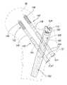
- FIG. 1is an environmental view of a fixation device according to the present teachings, illustrating a trochanteric procedure with interlocking fixation fasteners;
- FIG. 1Ais a sectional view of a proximal portion of an intramedullary implant of the fixation device of FIG. 1 ;
- FIG. 2is an enlarged view of a detail of FIG. 1 ;
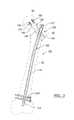
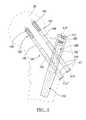
- FIG. 3is an environmental view of a fixation device according to the present teachings, illustrating a trochanteric procedure with reconstruction fixation fasteners;
- FIG. 4is an enlarged view of a detail of the fixation device of FIG. 3 ;
- FIG. 4Ais a partial cut-out view of a detail of the fixation device of FIG. 3
- FIG. 5A-Care various perspective view of an insert for the fixation devices of FIGS. 2 and 3 ;
- FIG. 5Dis a top view of the insert if FIG. 5A ;
- FIG. 5Eis a sectional view of the insert of FIG. 5A ;
- FIG. 6Ais a perspective view of a locking member according to the present teachings.
- FIG. 6Bis a side view of the locking member of FIG. 6A ;
- FIG. 6Cis a sectional view of the locking member of FIG. 6A ;
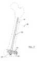
- FIG. 7is an environmental view of a fixation device according to the present teachings, illustrating a retrograde femoral procedure
- FIG. 8is an enlarged view of a detail of FIG. 7 ;
- FIG. 8Ais a side view of an intramedullary implant of the fixation device of FIG. 7 ;
- FIG. 8Bis another side view of an intramedullary implant of the fixation device of FIG. 7 , shown partially in section;
- FIGS. 9A and 9Bare perspective views of an insert for the fixation device of FIG. 7 ;
- FIG. 9Cis a sectional view of the insert of FIG. 9A ;
- FIG. 10is an environmental view of a fixation device according to the present teachings, illustrating a piriformis procedure with interlocking fixation fasteners
- FIG. 11is an enlarged view of a detail of FIG. 10 ;
- FIG. 12is an environmental view of a fixation device according to the present teachings, illustrating a piriformis procedure with reconstruction fixation fasteners
- FIG. 13is an enlarged view of a detail of FIG. 12 ;
- FIGS. 14A and 14Bare perspective views of an insert for the fixation devices of FIGS. 10 and 12 ;
- FIG. 14Cis a sectional view of the insert of FIG. 14A ;
- FIG. 15is a partially exploded perspective view of a portion of a fixation device according to the present teachings.
- FIG. 16is a perspective view illustrating an insert assembled with a locking member for an intramedullary nail according to the present teachings
- FIG. 17Ais an environmental perspective view of a fixation device according to the present teachings, illustrating a femoral procedure with transverse fixation fasteners;
- FIG. 17Bis an enlarged detail of FIG. 17A ;
- FIG. 18Ais a perspective view illustrating a first position of an insert for an intramedullary nail according to the present teachings
- FIG. 18Bis a perspective view illustrating a second position of the insert of FIG. 18A ;
- FIG. 19Ais a perspective view illustrating instruments for engaging and disengaging an insert for an intramedullary nail according to the present teachings.
- FIG. 19Bis an enlarged detail of FIG. 19A .
- FIGS. 1-6Cillustrate fixation devices for trochanteric femoral fixation
- FIGS. 7-9Bfor retrograde femoral fixation
- FIGS. 10-14Cfor piriformis femoral fixation
- FIGS. 15-19Bfor cortical tibia fixation.
- each fixation device 100can include an intramedullary nail or implant 102 , a telescopic clamp or securing device 200 that includes a hollow insert or similar movable member 160 and a cannulated set screw or similar locking member 180 , and various bone fasteners, including single-piece interlocking fasteners 104 and reconstruction fasteners 140 , including lag screws and telescopic screws slidable within sleeves.
- the movable member 160can be cannulated and can include a plurality of openings defining guiding bores configured for guiding the orientation of corresponding bone fasteners, as is described below in reference to particular procedures.
- the fixation device 100can include an elongated intramedullary implant 102 and an elongated interlocking fastener 104 .
- the intramedullary implant 102can include a shaft 110 having proximal and distal portions 112 , 114 and received in the intramedullary canal of the femur 80 .
- the proximal portion 112 of the intramedullary implant 102can include a proximal longitudinal bore 113 defining a longitudinal axis A.
- a proximal inner surface 111 of the proximal longitudinal bore 113can be of elliptical or other non-circular shape, having different major and minor diameters such that the cross-section has an elongated shape.
- the interlocking fastener 104can be oriented along the axis B passing through fastener bore 136 of the intramedullary implant 102 .
- the interlocking fastener 104can extend from a proximal lateral position near the greater trochanter 82 to a more distal medial position near the lesser trochanter 84 of the femur 80 , as shown in FIG. 2 .
- the interlocking fastener 104can include a head 106 and a shaft 108 with threads, ridges or other anchoring formations.
- One or more fasteners 104 ′can be inserted through the distal portion 114 of the intramedullary implant 102 for fixation to the distal femur.
- FIGS. 1A , 3 and 4another exemplary fixation device 100 according to the present teachings is shown implanted in the femur 80 for a reconstructive trochanteric procedure.
- Two reconstruction fasteners 140can be oriented along the directions defined by the first and second axes C and C′ passing through the corresponding first and second fastener bores 120 , 130 of the intramedullary implant 102 . Accordingly, the reconstruction fasteners 140 can be oriented at respective first and second angles ⁇ and ⁇ ′ relative to the longitudinal axis A, as described above.
- the reconstruction fasteners 140can extend from the vicinity of the greater trochanter 82 through the femoral neck 88 and into the femoral head 86 .
- Each reconstruction fastener 140can be a two-piece telescoping component including a sleeve 144 having a longitudinal bore 150 and a lag screw 142 that can pass through the bore 150 of the sleeve 144 and can slide relative to the sleeve 142 .
- the lag screw 142can include an unthreaded portion 140 receivable in the bore 150 of the sleeve 144 , and a threaded or bone anchoring portion 146 .
- either the interlocking fastener 104 or the reconstruction fasteners 140can be secured to the intramedullary implant 102 using a securing device 200 .
- the securing device 200can include a telescopic insert or movable member 160 , and a locking member 180 , such as a set screw.
- the movable member 160can be adapted for locking multiple fasteners to the intramedullary implant 102 , as shown in FIGS. 2 and 4 .
- the movable member 160can include a circular longitudinal bore 162 defining longitudinal axis “A 1 ”.
- the longitudinal axes A and A 1can substantially coincide.
- the movable member 160can define first and second guiding bores 164 , 166 oriented along the first and second axes C 1 , C 1 ′, as shown in FIG. 5C .
- the first and second axes C, C′ of the intramedullary implantcan substantially coincide with the first and second axes C 1 , C 1 ′ of the movable insert 160 .
- the first guiding bore 162can be fully enclosed within the movable member 160 and defined by first and second openings 170 , 172 .
- the first and second opening 170 , 172can be axially offset, can have closed perimeters and can be formed on opposing sides of the movable insert 160 along the first axis C 1 .
- the second guiding bore 166can be partially enclosed and defined by a third opening 174 having an open perimeter, as shown in FIG. 5C . It will be appreciated, however, that the second guiding bore 166 can also be fully enclosed and defined by two opposing openings along the axis C 1 ′ of the movable member 160 .
- the first and second reconstruction fasteners 140can be inserted through the first and second guiding bores 164 , 166 of the movable member 160 and through the corresponding first and second fastener bores 120 , 130 of the intramedullary implant 102 along the axes C, C′, as shown in FIG. 4 .
- the movable member 160can also include a third guiding bore 168 defined along axis B 1 and at an angle ⁇ relative to the longitudinal axis A 1 .
- the guiding bore 168can be defined by the first opening 170 and an opposite-side and longitudinally offset and open-perimeter fourth opening 176 .
- the perimeter of the opening fourth 176can intersect the perimeter of the third opening 174 , such that the fourth and third openings 174 , 176 can communicate, as shown in FIGS. 5A and 5C .
- An interlocking fastener 104can be received in the third guiding bore 168 passing through the third fastener bore 136 of the intramedullary implant 102 , when reconstruction fasteners 140 are not used, as shown in FIG. 2 .
- Ridges or other engagement formations 178can be provided in portions of any guiding bores of the movable member 160 for engaging corresponding threads or ridges 108 of interlocking fasteners 104 . Ridges 178 are illustrated, for example, in FIGS. 5A-5C in connection with trochanteric femoral procedures, in FIGS. 9A-9C for retrograde femoral procedures, in FIGS. 14A and 14B for piriformis femoral procedures, and in FIGS.
- the movable member 160can include a proximal end portion having an outer surface 161 with elliptical or elongated cross-section, and a body with a circular cylindrical surface 163 , as shown in FIGS. 5D and 5E .
- the outer surface 161 of the movable member 160can mate with the inner surface 111 of the proximal longitudinal bore 113 providing a keyed insertion, such that the movable member 160 can be inserted in the proximal longitudinal bore 113 in either one of two directions that are 180 degrees apart, as illustrated in FIG. 15 in connection with a movable member 160 and an intramedullary implant 102 for a tibial procedure described below.
- the longitudinal inner bore 162 of the movable member 160can be circular.
- the locking member 180can include a longitudinal bore 182 along a longitudinal axis A 2 .
- the locking member 180can include a threaded portion 184 and an unthreaded cylindrical portion 185 .
- the threaded portion 184can threadably engage a threaded inner surface 115 of the proximal longitudinal bore 113 of the intramedullary implant 102 , as shown in FIGS. 15 and 16 in connection with a movable member 160 and intramedullary implant 102 for a tibial procedure described below.
- the locking member 180can also include a distal flexible or resilient portion 186 defined by a plurality of legs 188 extending from the unthreaded portion 185 of the locking member 180 and separated by slots 190 .
- the resilient portion 186can define a step or flange 192 that can be retained into a groove 167 of the movable member 160 , shown in FIG. 5E , for example, when the resilient portion 186 is snap-fitted into the longitudinal bore 162 of the movable member 160 , as shown in FIGS. 15 and 16 .
- the locking member 180can also include a driver engagement formation 194 in a proximal portion of the bore 182 for engaging a driver 500 .
- the driver 500can be rotated for threadably engaging the locking member 180 with the intramedullary implant 102 , such that advancement of locking member 180 and corresponding advancement of the movable member distally or proximally can engage or disengage the movable member 160 from corresponding bone fasteners, such as fasteners 104 , as shown in FIGS. 19A , 19 B, 18 A and 18 B, in connection with a tibial procedure, as described in further detail below.
- the locking member 180can also include holes or other openings 196 that interrupt the threads of the threaded portion 184 .
- an exemplary fixation device 100is illustrated for a retrograde interlocking femoral fixation procedure.
- the retrograde intramedullary implant 102can be inserted in the distal portion of the femur 80 in a retrograde direction and can interlock at least up to three bone fasteners 104 using the movable member 160 and the locking member 180 of the securing device 200 .
- the retrograde intramedullary implant 102can define a plurality of through-bores, for example first, second and third bores 302 , 302 ′, 302 ′′ oriented transversely or at other different angles relative to longitudinal axis A of the retrograde intramedullary implant 102 .
- the movable member 160can include corresponding first, second and third guiding bores 304 , 304 ′, 304 ′′ oriented along first, second and third axes C 2 , C 2 ′, and C 2 ′, as shown in FIGS. 8 and 9A .
- the first and second guiding bores 304 , 304 ′can have closed perimeters, while the third guiding bore 304 ′′ can have an open perimeter defining a pair of opposing legs 306 .
- first, second and third guiding bores 304 , 304 ′, 304 ′′′can be aligned or circumferentially offset relative to one another or relative to the longitudinal axis A 1 , and can be parallel or non-parallel.
- the structure and function of the locking member 180 and other features of the securing device 200 and retrograde intramedullary implant 102are similar to those described above in connection with trochanteric procedure illustrated in FIGS. 1-6C and are not repeated.
- FIGS. 10-14Ban exemplary fixation device 100 according to the present teachings is illustrated for piriformis femoral procedures.
- FIGS. 10 and 11illustrate an interlocking piriformis fixation procedure
- FIGS. 12 and 13illustrate a reconstruction piriformis fixation procedure.
- the piriformis intramedullary implant 102 , the piriformis interlocking fastener 104 and the piriformis securing device 200are similar to the corresponding components described in connection with the trochanteric procedures illustrated in FIGS. 1-6C and their description is not repeated, except to note different or additional elements.
- the piriformis intramedullary implant 102can be configured for entry through the piriformis fossa near the greater trochanter 82 , as shown in FIG. 11 .
- the reconstruction fasteners 140can include single-piece piriformis lag screws 142 having a threaded portion 146 , an unthreaded portion 148 and a head 147 , as shown in FIG. 13 .
- the piriformis lag screws 142can pass through the piriformis intramedullary implant 102 along axes C, C′, and through the piriformis movable member 160 of piriformis securing device 200 along corresponding axes C 1 , C 1 ′ at angles ⁇ and ⁇ ′, which can be equal or different.
- the piriformis lag screws 142can be also be used with sleeves 144 in a telescopic manner, as described in connection with the trochanteric procedure illustrated in FIG. 4 .
- FIGS. 14A-14CVarious views of the piriformis movable member 160 are illustrated in FIGS. 14A-14C using the same reference characters as used in FIGS. 5A-5E to describe similar elements.
- the tibial movable member 160can include first, second and third bores 171 , 173 , 175 transversely oriented relative to the longitudinal axis A 1 of the movable member 160 , and circumferentially offset relative to one another, as shown in FIGS. 16 , 17 A, and 17 B.
- the first and second bores 171 , 173can have closed perimeters and receive corresponding interlocking fasteners 104 , such as cortical screws that pass through corresponding bores of the tibial intramedullary implant 102 for fixation into the tibia 70 , as shown in FIGS. 17A and 17B .
- the third bore 175can have an open perimeter defining two opposing legs 169 .
- FIGS. 18A and 18Buse of the securing device 200 for active compression of fractures is illustrated.
- An interlocking fastener 104can pass through the third bore 175 of the movable member 160 and through an elongated slot 103 of the intramedullary implant 102 .
- FIG. 18Aillustrates the securing device 200 in a first position that allows dynamic movement along the slot 103 .
- FIG. 18Billustrates the securing device 200 in a second position, in which the fastener 104 engages the distal wall of the slot 103 .
- the movable member 160can be moved from the first to the second position by rotation of the locking member 180 , such that the locking member 180 threadably moves relative to the intramedullary implant 102 and forces the movable member 160 to move distally in the direction of arrow D relative to the intramedullary implant 102 .
- the targeting device 600can include a radiolucent targeting arm 602 , a driving handle 604 and a cannulated connecting bolt 606 that connects the targeting device 600 to the intramedullary implant 102 .
- a driver 500 with a flexible driving shaft 502can pass through the bore 608 of the connecting bolt 606 and engage the driver engagement formations 194 of the locking member 180 .
- Rotating the driver shaft 502 clockwise or counterclockwiserotates the locking member 180 correspondingly, and correspondingly urges the movable member 160 distally to a position of engagement with the interlocking fasteners 104 , or proximally to a position of disengagement.
- any interlocking fastener 104can be removed by rotating the interlocking fastener 104 , such that the threaded shaft 108 of the interlocking fastener 104 moves relative to the ridges 178 of the corresponding bore of the movable member 160 , while the securing device 200 remains in its locked position relative to the intramedullary implant 102 .
- the present teachingsprovide a securing device for intramedullary implant fixation that can be used telescopically to lock the intramedullary implant with more than one bone fasteners in interlocking or reconstructive procedures for the femur and tibia. Further, active compression of a fracture site can be obtained with the same securing device.
Landscapes
- Health & Medical Sciences (AREA)
- Orthopedic Medicine & Surgery (AREA)
- Surgery (AREA)
- Life Sciences & Earth Sciences (AREA)
- Heart & Thoracic Surgery (AREA)
- Nuclear Medicine, Radiotherapy & Molecular Imaging (AREA)
- Engineering & Computer Science (AREA)
- Biomedical Technology (AREA)
- Neurology (AREA)
- Medical Informatics (AREA)
- Molecular Biology (AREA)
- Animal Behavior & Ethology (AREA)
- General Health & Medical Sciences (AREA)
- Public Health (AREA)
- Veterinary Medicine (AREA)
- Surgical Instruments (AREA)
- Prostheses (AREA)
Abstract
Description
Claims (24)
Priority Applications (12)
| Application Number | Priority Date | Filing Date | Title |
|---|---|---|---|
| US11/627,575US8303590B2 (en) | 2007-01-26 | 2007-01-26 | Lockable intramedullary fixation device |
| AU2008211285AAU2008211285B2 (en) | 2007-01-26 | 2008-01-17 | Lockable intramedullary fixation device |
| CN200880006581.2ACN101626733B (en) | 2007-01-26 | 2008-01-17 | Lockable intermedullary fixation device |
| PCT/US2008/000568WO2008094407A1 (en) | 2007-01-26 | 2008-01-17 | Lockable intramedullary fixation device |
| ES08724539TES2379027T3 (en) | 2007-01-26 | 2008-01-17 | Intermedullary locking device lockable |
| EP08724539AEP2109404B1 (en) | 2007-01-26 | 2008-01-17 | Lockable intermedullary fixation device |
| AT08724539TATE540629T1 (en) | 2007-01-26 | 2008-01-17 | LOCKABLE INTRAMEDULLARY FASTENING DEVICE |
| US12/117,765US8157802B2 (en) | 2007-01-26 | 2008-05-09 | Intramedullary implant with locking and compression devices |
| US12/183,142US9320551B2 (en) | 2007-01-26 | 2008-07-31 | Lockable intramedullary fixation device |
| US13/415,336US9308031B2 (en) | 2007-01-26 | 2012-03-08 | Lockable intramedullary fixation device |
| US15/088,397US9572606B2 (en) | 2007-01-26 | 2016-04-01 | Lockable intramedullary fixation device |
| US15/095,431US9943346B2 (en) | 2007-01-26 | 2016-04-11 | Lockable intramedullary fixation device |
Applications Claiming Priority (1)
| Application Number | Priority Date | Filing Date | Title |
|---|---|---|---|
| US11/627,575US8303590B2 (en) | 2007-01-26 | 2007-01-26 | Lockable intramedullary fixation device |
Related Parent Applications (1)
| Application Number | Title | Priority Date | Filing Date |
|---|---|---|---|
| US12/117,765Continuation-In-PartUS8157802B2 (en) | 2007-01-26 | 2008-05-09 | Intramedullary implant with locking and compression devices |
Related Child Applications (2)
| Application Number | Title | Priority Date | Filing Date |
|---|---|---|---|
| US12/117,765Continuation-In-PartUS8157802B2 (en) | 2007-01-26 | 2008-05-09 | Intramedullary implant with locking and compression devices |
| US12/183,142Continuation-In-PartUS9320551B2 (en) | 2007-01-26 | 2008-07-31 | Lockable intramedullary fixation device |
Publications (2)
| Publication Number | Publication Date |
|---|---|
| US20080183171A1 US20080183171A1 (en) | 2008-07-31 |
| US8303590B2true US8303590B2 (en) | 2012-11-06 |
Family
ID=39357960
Family Applications (1)
| Application Number | Title | Priority Date | Filing Date |
|---|---|---|---|
| US11/627,575Active2030-05-26US8303590B2 (en) | 2007-01-26 | 2007-01-26 | Lockable intramedullary fixation device |
Country Status (7)
| Country | Link |
|---|---|
| US (1) | US8303590B2 (en) |
| EP (1) | EP2109404B1 (en) |
| CN (1) | CN101626733B (en) |
| AT (1) | ATE540629T1 (en) |
| AU (1) | AU2008211285B2 (en) |
| ES (1) | ES2379027T3 (en) |
| WO (1) | WO2008094407A1 (en) |
Cited By (20)
| Publication number | Priority date | Publication date | Assignee | Title |
|---|---|---|---|---|
| US20120130502A1 (en)* | 2006-12-07 | 2012-05-24 | Ihip Surgical, Llc | Method and apparatus for hip replacement |
| US20130158553A1 (en)* | 2011-12-20 | 2013-06-20 | Synthes Usa, Llc | Self Centering Feature for an Intramedullary Nail |
| US8795381B2 (en) | 2006-12-07 | 2014-08-05 | Ihip Surgical, Llc | Methods and systems for hip replacement |
| US8974540B2 (en) | 2006-12-07 | 2015-03-10 | Ihip Surgical, Llc | Method and apparatus for attachment in a modular hip replacement or fracture fixation device |
| US9320551B2 (en) | 2007-01-26 | 2016-04-26 | Biomet Manufacturing, Llc | Lockable intramedullary fixation device |
| US9662153B2 (en) | 2007-12-17 | 2017-05-30 | Wright Medical Technology, Inc. | Guide assembly for intramedullary fixation and method of using the same |
| US9782206B2 (en) | 2011-02-08 | 2017-10-10 | Stryker European Holdings I, Llc | Implant system for bone fixation |
| US9895177B2 (en) | 2016-01-15 | 2018-02-20 | ARTHREX, GmbH | Bone fixation device for treatment of femoral fractures |
| US9895178B2 (en)* | 2015-04-24 | 2018-02-20 | Biomet Manufacturing, Llc | Variable angle locking insert for intramedullary nail |
| US9943346B2 (en) | 2007-01-26 | 2018-04-17 | Biomet Manufacturing, Llc | Lockable intramedullary fixation device |
| WO2018125779A1 (en) | 2016-12-28 | 2018-07-05 | William Scott Van Dyke | Joint compression instrumentation |
| US10492803B2 (en) | 2016-09-22 | 2019-12-03 | Globus Medical, Inc. | Systems and methods for intramedullary nail implantation |
| US10610270B2 (en) | 2018-01-15 | 2020-04-07 | Glw, Inc. | Hybrid intramedullary rods |
| US11083503B2 (en) | 2016-09-22 | 2021-08-10 | Globus Medical, Inc. | Systems and methods for intramedullary nail implantation |
| US11426220B2 (en) | 2017-10-11 | 2022-08-30 | Howmedica Osteonics Corp. | Humeral fixation plate guides |
| US11617604B2 (en) | 2020-04-15 | 2023-04-04 | DePuy Synthes Products, Inc. | Intramedullary nail assembly |
| US11633219B2 (en) | 2019-06-26 | 2023-04-25 | Globus Medical, Inc. | Fenestrated pedicle nail |
| RU2805794C1 (en)* | 2023-03-02 | 2023-10-24 | Общество С Ограниченной Ответственностью "Орто-Сув" | Intramedullary nail for osteosynthesis |
| US11857228B2 (en) | 2020-03-06 | 2024-01-02 | Stryker European Operations Limited | Set screw for femoral nail |
| US12207849B2 (en) | 2020-03-06 | 2025-01-28 | Stryker European Operations Limited | Set screw for femoral nail |
Families Citing this family (48)
| Publication number | Priority date | Publication date | Assignee | Title |
|---|---|---|---|---|
| US8157802B2 (en)* | 2007-01-26 | 2012-04-17 | Ebi, Llc | Intramedullary implant with locking and compression devices |
| US7918853B2 (en) | 2007-03-20 | 2011-04-05 | Smith & Nephew, Inc. | Orthopaedic plate and screw assembly |
| US8394103B2 (en)* | 2007-10-16 | 2013-03-12 | Biomet Manufacturing Corp. | Method and apparatus for orthopedic fixation |
| CA2781407A1 (en) | 2008-01-14 | 2009-07-23 | Michael P. Brenzel | Apparatus and methods for fracture repair |
| CN104068925B (en) | 2008-03-26 | 2017-07-14 | 斯恩蒂斯有限公司 | For the universal anchor by physical attachment on bone tissue |
| US20110046625A1 (en)* | 2008-05-07 | 2011-02-24 | Tornier | Surgical technique and apparatus for proximal humeral fracture repair |
| CN102046111A (en) | 2008-06-05 | 2011-05-04 | 斯恩蒂斯有限公司 | Articulating disc implant |
| EP2339976B1 (en) | 2008-07-09 | 2016-03-16 | Icon Orthopaedic Concepts, LLC | Ankle arthrodesis nail and outrigger assembly |
| US8414584B2 (en) | 2008-07-09 | 2013-04-09 | Icon Orthopaedic Concepts, Llc | Ankle arthrodesis nail and outrigger assembly |
| US10251757B2 (en) | 2008-09-17 | 2019-04-09 | Skeletal Dynamics Llc | Grooved slot allowing adjustment of the position of a bone fixation device for osteosynthesis |
| US9095440B2 (en)* | 2008-09-17 | 2015-08-04 | Skeletal Dynamics, Llc | Intramedullary arthrodesis nail and method of use |
| US9060808B2 (en) | 2008-12-05 | 2015-06-23 | DePuy Synthes Products, Inc. | Anchor-in-anchor system for use in bone fixation |
| JP5759900B2 (en)* | 2008-12-05 | 2015-08-05 | ジンテス ゲゼルシャフト ミット ベシュレンクテル ハフツング | Anchor-in-anchor system for use in bone fixation |
| US9295504B2 (en)* | 2009-03-31 | 2016-03-29 | Biomet C.V. | Intramedullary nail with locking key |
| US8834469B2 (en)* | 2009-06-30 | 2014-09-16 | Smith & Nephew, Inc. | Orthopaedic implant and fastener assembly |
| US8915917B2 (en) | 2009-08-13 | 2014-12-23 | Cork Institute Of Technology | Intramedullary nails for long bone fracture setting |
| US20110178520A1 (en) | 2010-01-15 | 2011-07-21 | Kyle Taylor | Rotary-rigid orthopaedic rod |
| WO2011091052A1 (en) | 2010-01-20 | 2011-07-28 | Kyle Taylor | Apparatus and methods for bone access and cavity preparation |
| US8764751B2 (en)* | 2010-03-04 | 2014-07-01 | Skeletal Dynamics, Llc | Endosteal nail plate for fixing bone segments |
| WO2011112615A1 (en) | 2010-03-08 | 2011-09-15 | Krinke Todd A | Apparatus and methods for securing a bone implant |
| US8540714B2 (en)* | 2010-05-11 | 2013-09-24 | Orthopediatrics Corp. | Pediatric intramedullary nail |
| CN102338283B (en)* | 2010-07-23 | 2015-06-03 | 阳江纳谷科技有限公司 | Electric torch capable of condensing light |
| KR101789498B1 (en)* | 2010-07-09 | 2017-10-25 | 신세스 게엠바하 | Intramedullary nail |
| US9782617B2 (en) | 2010-09-19 | 2017-10-10 | Thomas Alan Ferguson, JR. | Piri-stretcher system |
| US9101794B2 (en) | 2010-09-19 | 2015-08-11 | Thomas Alan Ferguson, JR. | Piri-stretcher |
| USD703824S1 (en) | 2010-09-19 | 2014-04-29 | Thomas Alan Ferguson, JR. | Leg stretching device |
| US8876821B2 (en)* | 2010-11-24 | 2014-11-04 | Kyle Kinmon | Intramedullary nail, system, and method with dynamic compression |
| BR112013020956B1 (en)* | 2011-02-14 | 2020-12-08 | Synthes Gmbh | bone fixation set |
| CN104519833B (en)* | 2011-11-30 | 2017-09-26 | 史密夫和内修有限公司 | Orthopedic implant with powered penetrating fixation slot |
| ES2656974T3 (en) | 2012-01-19 | 2018-03-01 | Stryker European Holdings I, Llc | Cuff for suprarrotulian surgery |
| DE202012103384U1 (en)* | 2012-09-05 | 2012-09-24 | Signus Medizintechnik Gmbh | Pelvic ring implant |
| EP2916742B1 (en) | 2012-11-12 | 2018-08-29 | Ziran, Navid | Dynamic axial nail for intramedullary treatment of long bone fractures |
| US9480509B2 (en)* | 2013-11-07 | 2016-11-01 | Four Studies Ltd. | Osteosynthesis apparatus for proximal femur fracture and master screw-type screw apparatus for osteosynthesis apparatus for proximal femur fracture |
| CN105939677A (en) | 2013-12-12 | 2016-09-14 | 康文图斯整形外科公司 | Tissue displacement tools and methods |
| US9480506B2 (en)* | 2015-01-11 | 2016-11-01 | Mohammad Javad Zehtab | Compression device for interlocking compression nailing systems and method of use |
| TWI589263B (en)* | 2015-06-04 | 2017-07-01 | 愛派司生技股份有限公司 | A fixation system for hip fracture use thereof |
| AU2017251120B2 (en)* | 2016-04-14 | 2022-01-27 | Orthoxel Dac | An intramedullary nail system |
| WO2018042595A1 (en)* | 2016-09-01 | 2018-03-08 | 株式会社オーミック | Thighbone fixing tool |
| CN106618719B (en)* | 2017-01-11 | 2023-04-18 | 海口市人民医院 | Hollow lag screw guide pin aiming fixer for reduction through posterior femoral lesser tuberosity |
| US10251682B2 (en)* | 2017-03-22 | 2019-04-09 | DePuy Synthes Products, Inc. | Distal radius nail |
| WO2019010252A2 (en) | 2017-07-04 | 2019-01-10 | Conventus Orthopaedics, Inc. | APPARATUS AND METHODS FOR TREATING BONES |
| CN107582218A (en)* | 2017-10-09 | 2018-01-16 | 北京爱康宜诚医疗器材有限公司 | Pattern of fusion femoral stem system |
| US11446072B2 (en) | 2017-10-10 | 2022-09-20 | DePuy Synthes Products, Inc. | Self-retaining nail to insertion handle interface |
| US10932828B2 (en) | 2018-01-25 | 2021-03-02 | Advanced Orthopaedic Solutions, Inc. | Bone nail |
| EP3626184A1 (en)* | 2018-09-21 | 2020-03-25 | OrthoXel DAC | A femoral nail system |
| IT201900005180A1 (en)* | 2019-04-05 | 2020-10-05 | Enrico Paganelli | ENDOMIDOLLAR NAIL |
| US20220192720A1 (en)* | 2020-12-18 | 2022-06-23 | DePuy Synthes Products, Inc. | Screw-in-screw bone fixation system |
| US12004785B2 (en) | 2022-04-21 | 2024-06-11 | DePuy Synthes Products, Inc. | Retrograde femoral intramedullary nail, and related systems and methods |
Citations (91)
| Publication number | Priority date | Publication date | Assignee | Title |
|---|---|---|---|---|
| US2068152A (en) | 1934-03-03 | 1937-01-19 | Trumbull Electric Mfg Co | Solderless electrical terminal |
| US2201674A (en) | 1938-03-12 | 1940-05-21 | Trumbull Electric Mfg Co | Electrical terminal |
| US2222156A (en) | 1939-04-18 | 1940-11-19 | Trumbull Electric Mfg Co | Solderless wire terminal |
| US2725915A (en)* | 1951-09-21 | 1955-12-06 | Nylok Corp | Self-locking stud insert |
| US2789276A (en) | 1954-04-15 | 1957-04-16 | Crouse Hinds Co | Terminal clamp |
| US2913031A (en)* | 1958-04-03 | 1959-11-17 | Long Lok Corp | Self-locking screw threaded fastener member having an elongated resilient insert |
| US3308865A (en)* | 1965-05-04 | 1967-03-14 | American Standard Products Inc | Bolt anchoring means |
| US3501993A (en) | 1968-12-17 | 1970-03-24 | Henry F Swenson | Setscrew with rotatable plastic end |
| US3709218A (en) | 1970-04-24 | 1973-01-09 | W Halloran | Combination intramedullary fixation and external bone compression apparatus |
| US3836941A (en) | 1973-07-05 | 1974-09-17 | Thomas & Betts Corp | Electrical connector with resilient pressure pad |
| US3990438A (en)* | 1975-04-21 | 1976-11-09 | Pritchard Rowland W | Bone fracture fixation and compression apparatus |
| US4354399A (en) | 1978-11-29 | 1982-10-19 | Shimano Industrial Company Limited | Handle bar fixing device for a bicycle |
| US4450835A (en) | 1981-02-20 | 1984-05-29 | Howmedica, Inc. | Method and system for inserting a surgical wire |
| US4622959A (en)* | 1985-03-05 | 1986-11-18 | Marcus Randall E | Multi-use femoral intramedullary nail |
| US4710075A (en) | 1986-10-01 | 1987-12-01 | Boehringer Mannheim Corporation | Adjustable drill gauge |
| US4733661A (en) | 1987-04-27 | 1988-03-29 | Palestrant Aubrey M | Guidance device for C.T. guided drainage and biopsy procedures |
| US4756307A (en) | 1987-02-09 | 1988-07-12 | Zimmer, Inc. | Nail device |
| US4776330A (en) | 1986-06-23 | 1988-10-11 | Pfizer Hospital Products Group, Inc. | Modular femoral fixation system |
| US4828562A (en) | 1988-02-04 | 1989-05-09 | Pfizer Hospital Products Group, Inc. | Anterior cruciate ligament prosthesis |
| US4827917A (en) | 1986-12-30 | 1989-05-09 | Richards Medical Company | Fermoral fracture device |
| US4858602A (en) | 1985-12-06 | 1989-08-22 | Howmedica GmbH Werk Schonkirchen | Bone nail for the treatment of upper arm fractures |
| US4875475A (en) | 1984-11-30 | 1989-10-24 | Synthes (U.S.A.) | Device for treating a bone |
| US4895572A (en) | 1988-11-25 | 1990-01-23 | Ira Chernoff | Interlocking femoral prosthesis device |
| US5034013A (en) | 1989-04-24 | 1991-07-23 | Zimmer Inc. | Intramedullary nail |
| US5041115A (en) | 1988-03-14 | 1991-08-20 | Synthes (U.S.A.) | Medullary nail for the tibia |
| US5066296A (en) | 1989-02-02 | 1991-11-19 | Pfizer Hopsital Products Group, Inc. | Apparatus for treating a fracture |
| US5112333A (en) | 1990-02-07 | 1992-05-12 | Fixel Irving E | Intramedullary nail |
| US5190544A (en) | 1986-06-23 | 1993-03-02 | Pfizer Hospital Products Group, Inc. | Modular femoral fixation system |
| US5295991A (en) | 1991-05-24 | 1994-03-22 | Synthes (U.S.A.) | Surgical instrument for positioning osteosynthetic elements |
| US5383525A (en)* | 1992-08-26 | 1995-01-24 | Camco International Inc. | Threaded ring retention mechanism |
| WO1995034248A1 (en) | 1994-06-10 | 1995-12-21 | Michael Gordon Matthews | Intramedullary nail |
| US5505734A (en) | 1993-10-06 | 1996-04-09 | Gruppo Industriale Bioimpianti S.R.L. | Lockable intramedullary nail for the humerus |
| US5549610A (en) | 1994-10-31 | 1996-08-27 | Smith & Nephew Richards Inc. | Femoral intramedullary nail |
| US5653709A (en)* | 1992-12-04 | 1997-08-05 | Synthes (U.S.A.) | Modular marrow nail |
| US5658287A (en)* | 1995-06-05 | 1997-08-19 | Gruppo Industriale Bioimpianti S.R.L. | Locked intramedullary nail, suitable in particular for fractures of the femur |
| US5690515A (en) | 1996-07-16 | 1997-11-25 | Cipolla; Frank G. | Splicing block for multi-strand electric cable |
| US5697930A (en) | 1995-01-30 | 1997-12-16 | Asahi Kogaku Kogyo Kabushiki Kaisha | Intramedullary nail for humerus |
| US5704939A (en) | 1996-04-09 | 1998-01-06 | Justin; Daniel F. | Intramedullary skeletal distractor and method |
| US5728128A (en) | 1997-02-11 | 1998-03-17 | Wright Medical Technology, Inc. | Femoral neck anteversion guide |
| US5935127A (en) | 1997-12-17 | 1999-08-10 | Biomet, Inc. | Apparatus and method for treatment of a fracture in a long bone |
| US6004324A (en) | 1996-11-22 | 1999-12-21 | Howmedica Gmbh | Adjustable locking nail |
| US6010506A (en) | 1998-09-14 | 2000-01-04 | Smith & Nephew, Inc. | Intramedullary nail hybrid bow |
| US6019761A (en) | 1998-12-23 | 2000-02-01 | Gustilo; Ramon B. | Intramedullary nail and method of use |
| US6036696A (en) | 1997-12-19 | 2000-03-14 | Stryker Technologies Corporation | Guide-pin placement device and method of use |
| US6080024A (en) | 1999-03-08 | 2000-06-27 | Hubbell Incorporated | Multi-stranded conductor terminal assembly having resilient contact pad with undulations |
| US6106528A (en)* | 1997-02-11 | 2000-08-22 | Orthomatrix, Inc. | Modular intramedullary fixation system and insertion instrumentation |
| US6120504A (en) | 1998-12-10 | 2000-09-19 | Biomet Inc. | Intramedullary nail having dual distal bore formation |
| US6221074B1 (en)* | 1999-06-10 | 2001-04-24 | Orthodyne, Inc. | Femoral intramedullary rod system |
| US6228086B1 (en)* | 1997-03-19 | 2001-05-08 | Stryker Trauma-Selzach Ag | Modular intramedullary nail |
| WO2001043652A1 (en) | 1999-12-15 | 2001-06-21 | Wolfram Mittelmeier | Compression bone nail |
| US6296645B1 (en) | 1999-04-09 | 2001-10-02 | Depuy Orthopaedics, Inc. | Intramedullary nail with non-metal spacers |
| US6406477B1 (en) | 2000-07-27 | 2002-06-18 | Koi Inc. | Intramedullary nail |
| US20020133156A1 (en) | 1999-06-10 | 2002-09-19 | Cole J. Dean | Femoral intramedullary rod system |
| US6461360B1 (en) | 1999-05-12 | 2002-10-08 | Sulzer Orthopedics Ltd. | Locking nail for the repair of femur shaft fractures |
| US20020156473A1 (en)* | 2001-04-24 | 2002-10-24 | Bramlet Dale G. | Intramedullary hip nail with bifurcated lock |
| US6547791B1 (en) | 1998-07-27 | 2003-04-15 | Stryker Trauma - Selzach Ag | Retrograde tibial nail |
| US6562042B2 (en) | 2000-02-02 | 2003-05-13 | Owen A. Nelson | Orthopedic implant used to repair intertrochanteric fractures and a method for inserting the same |
| US6579294B2 (en) | 2000-07-26 | 2003-06-17 | Stryker Trauma Gmbh | Locking nail for fracture fixation |
| WO2003061495A2 (en) | 2002-01-23 | 2003-07-31 | Disc-O-Tech Medical Technologies, Ltd. | Locking mechanism for intramedullary nails |
| US20030195515A1 (en) | 1999-10-21 | 2003-10-16 | Sohngen Gary W. | Modular intramedullary nail |
| WO2003094763A1 (en) | 2002-05-14 | 2003-11-20 | Tantum Ag | Osteosynthesis device |
| US6702816B2 (en)* | 2001-05-25 | 2004-03-09 | Sulzer Orthopedics Ltd. | Femur marrow nail for insertion at the knee joint |
| US20040138663A1 (en)* | 2001-05-23 | 2004-07-15 | Yona Kosashvili | Magnetically-actuable intramedullary device |
| US20040158252A1 (en)* | 2003-01-23 | 2004-08-12 | Stryker Trauma Gmbh | Implant for osteosynthesis |
| WO2004082493A1 (en) | 2003-03-20 | 2004-09-30 | Stryker Trauma Sa | A bone connection device |
| US6808527B2 (en) | 2000-04-10 | 2004-10-26 | Depuy Orthopaedics, Inc. | Intramedullary nail with snap-in window insert |
| WO2004100810A1 (en) | 2003-05-17 | 2004-11-25 | Depuy International Limited | An intramedullary nail assembly |
| US20040260307A1 (en) | 2003-06-20 | 2004-12-23 | Stryker Trauma Gmbh | Drilling tool guide wire alignment device |
| US6835197B2 (en) | 2001-10-17 | 2004-12-28 | Christoph Andreas Roth | Bone fixation system |
| US20050010223A1 (en)* | 2003-07-08 | 2005-01-13 | Yechiel Gotfried | Intramedullary nail system and method for fixation of a fractured bone |
| US20050101958A1 (en) | 2002-11-04 | 2005-05-12 | Michael Adam | Bone fixing system |
| US20050107790A1 (en) | 2001-12-29 | 2005-05-19 | Benwen Qian | Intramedullary pin |
| US20050143739A1 (en)* | 2003-12-25 | 2005-06-30 | Homs Engineering Inc. | Intramedullary nail |
| EP1557131A1 (en) | 2004-01-20 | 2005-07-27 | Depuy Orthopaedics, Inc. | Intramedullary nail for static or dynamic fixation |
| US20050203510A1 (en)* | 2004-03-11 | 2005-09-15 | Sohngen Gary W. | Fixation instrument for treating a bone fracture |
| US6960212B2 (en) | 2001-02-12 | 2005-11-01 | Aesculap Ii, Inc. | Rod to rod connector |
| US20060111716A1 (en)* | 2003-03-21 | 2006-05-25 | Andre Schlienger | Intramedullary nail |
| US20060111717A1 (en)* | 2003-05-09 | 2006-05-25 | Aesculap Ag & Co. Kg | Implant with a threaded bore for a bone screw |
| US20060149264A1 (en) | 2004-12-20 | 2006-07-06 | Castaneda Javier E | Screw locking systems for bone plates |
| US20060173457A1 (en)* | 2005-02-01 | 2006-08-03 | Tornier | Humeral nail |
| US20060200141A1 (en)* | 2005-02-18 | 2006-09-07 | Si Janna | Hindfoot nail |
| US20060200160A1 (en) | 2005-02-18 | 2006-09-07 | Ebi, L.P. | Internal fixation assemblies and associated instruments |
| WO2006107222A2 (en) | 2005-04-05 | 2006-10-12 | Orthopaedic Innovations Manufacturing, Inc. | Intramedullary nail distal targeting device |
| US20060235395A1 (en) | 2003-08-29 | 2006-10-19 | Robert Frigg | Intramedullary nail |
| WO2007038560A1 (en) | 2005-09-28 | 2007-04-05 | Smith & Nephew, Inc. | Instrumentation for reducing fractures , particularly femoral neck |
| US20070233100A1 (en) | 2006-03-31 | 2007-10-04 | Metzinger Anthony J | Variable angle intramedullary nail |
| US20080221577A1 (en) | 2007-01-26 | 2008-09-11 | Ebi, Llc | Intramedullary implant with locking and compression devices |
| US20080294164A1 (en) | 2007-01-26 | 2008-11-27 | Ebi, Llc. | Lockable intramedullary fixation device |
| US20080300637A1 (en) | 2005-07-25 | 2008-12-04 | Smith & Nephew, Inc. | Systems and methods for using polyaxial plates |
| US20090048600A1 (en) | 2007-06-22 | 2009-02-19 | Anthem Orthopaedics Van, Llc | Intramedullary rod with pivotable fastener and method for using same |
| US7527627B2 (en)* | 2003-09-08 | 2009-05-05 | Smith & Nephew, Inc. | Orthopaedic implant and screw assembly |
- 2007
- 2007-01-26USUS11/627,575patent/US8303590B2/enactiveActive
- 2008
- 2008-01-17CNCN200880006581.2Apatent/CN101626733B/enactiveActive
- 2008-01-17EPEP08724539Apatent/EP2109404B1/enactiveActive
- 2008-01-17AUAU2008211285Apatent/AU2008211285B2/enactiveActive
- 2008-01-17WOPCT/US2008/000568patent/WO2008094407A1/enactiveApplication Filing
- 2008-01-17ATAT08724539Tpatent/ATE540629T1/enactive
- 2008-01-17ESES08724539Tpatent/ES2379027T3/enactiveActive
Patent Citations (120)
| Publication number | Priority date | Publication date | Assignee | Title |
|---|---|---|---|---|
| US2068152A (en) | 1934-03-03 | 1937-01-19 | Trumbull Electric Mfg Co | Solderless electrical terminal |
| US2201674A (en) | 1938-03-12 | 1940-05-21 | Trumbull Electric Mfg Co | Electrical terminal |
| US2222156A (en) | 1939-04-18 | 1940-11-19 | Trumbull Electric Mfg Co | Solderless wire terminal |
| US2725915A (en)* | 1951-09-21 | 1955-12-06 | Nylok Corp | Self-locking stud insert |
| US2789276A (en) | 1954-04-15 | 1957-04-16 | Crouse Hinds Co | Terminal clamp |
| US2913031A (en)* | 1958-04-03 | 1959-11-17 | Long Lok Corp | Self-locking screw threaded fastener member having an elongated resilient insert |
| US3308865A (en)* | 1965-05-04 | 1967-03-14 | American Standard Products Inc | Bolt anchoring means |
| US3501993A (en) | 1968-12-17 | 1970-03-24 | Henry F Swenson | Setscrew with rotatable plastic end |
| US3709218A (en) | 1970-04-24 | 1973-01-09 | W Halloran | Combination intramedullary fixation and external bone compression apparatus |
| US3836941A (en) | 1973-07-05 | 1974-09-17 | Thomas & Betts Corp | Electrical connector with resilient pressure pad |
| US3990438A (en)* | 1975-04-21 | 1976-11-09 | Pritchard Rowland W | Bone fracture fixation and compression apparatus |
| US4354399A (en) | 1978-11-29 | 1982-10-19 | Shimano Industrial Company Limited | Handle bar fixing device for a bicycle |
| US4450835A (en) | 1981-02-20 | 1984-05-29 | Howmedica, Inc. | Method and system for inserting a surgical wire |
| US4875475A (en) | 1984-11-30 | 1989-10-24 | Synthes (U.S.A.) | Device for treating a bone |
| US4622959A (en)* | 1985-03-05 | 1986-11-18 | Marcus Randall E | Multi-use femoral intramedullary nail |
| US4858602A (en) | 1985-12-06 | 1989-08-22 | Howmedica GmbH Werk Schonkirchen | Bone nail for the treatment of upper arm fractures |
| US5041114A (en) | 1986-06-23 | 1991-08-20 | Pfizer Hospital Products Group, Inc. | Modular femoral fixation system |
| US4776330A (en) | 1986-06-23 | 1988-10-11 | Pfizer Hospital Products Group, Inc. | Modular femoral fixation system |
| US5190544A (en) | 1986-06-23 | 1993-03-02 | Pfizer Hospital Products Group, Inc. | Modular femoral fixation system |
| US4710075A (en) | 1986-10-01 | 1987-12-01 | Boehringer Mannheim Corporation | Adjustable drill gauge |
| US4827917A (en) | 1986-12-30 | 1989-05-09 | Richards Medical Company | Fermoral fracture device |
| US4756307A (en) | 1987-02-09 | 1988-07-12 | Zimmer, Inc. | Nail device |
| US4733661A (en) | 1987-04-27 | 1988-03-29 | Palestrant Aubrey M | Guidance device for C.T. guided drainage and biopsy procedures |
| US4828562A (en) | 1988-02-04 | 1989-05-09 | Pfizer Hospital Products Group, Inc. | Anterior cruciate ligament prosthesis |
| US5041115A (en) | 1988-03-14 | 1991-08-20 | Synthes (U.S.A.) | Medullary nail for the tibia |
| US4895572A (en) | 1988-11-25 | 1990-01-23 | Ira Chernoff | Interlocking femoral prosthesis device |
| US5066296A (en) | 1989-02-02 | 1991-11-19 | Pfizer Hopsital Products Group, Inc. | Apparatus for treating a fracture |
| US5034013A (en) | 1989-04-24 | 1991-07-23 | Zimmer Inc. | Intramedullary nail |
| US5112333A (en) | 1990-02-07 | 1992-05-12 | Fixel Irving E | Intramedullary nail |
| US5295991A (en) | 1991-05-24 | 1994-03-22 | Synthes (U.S.A.) | Surgical instrument for positioning osteosynthetic elements |
| US5383525A (en)* | 1992-08-26 | 1995-01-24 | Camco International Inc. | Threaded ring retention mechanism |
| US5653709A (en)* | 1992-12-04 | 1997-08-05 | Synthes (U.S.A.) | Modular marrow nail |
| US5505734A (en) | 1993-10-06 | 1996-04-09 | Gruppo Industriale Bioimpianti S.R.L. | Lockable intramedullary nail for the humerus |
| WO1995034248A1 (en) | 1994-06-10 | 1995-12-21 | Michael Gordon Matthews | Intramedullary nail |
| US5779705A (en) | 1994-06-10 | 1998-07-14 | Matthews; Michael Gordon | Intramedullary nail |
| EP0764006A1 (en) | 1994-06-10 | 1997-03-26 | Michael Gordon Matthews | Intramedullary nail |
| GB2290478A (en) | 1994-06-10 | 1996-01-03 | Michael Gordon Matthews | Intramedullary nail fracture stabilisation |
| DE69511549T2 (en) | 1994-06-10 | 2000-03-30 | Michael Gordon Matthews | MARKING NAIL |
| ES2134479T3 (en) | 1994-06-10 | 1999-10-01 | Michael Gordon Matthews | INTRAMEDULAR NAIL. |
| US5549610A (en) | 1994-10-31 | 1996-08-27 | Smith & Nephew Richards Inc. | Femoral intramedullary nail |
| US5697930A (en) | 1995-01-30 | 1997-12-16 | Asahi Kogaku Kogyo Kabushiki Kaisha | Intramedullary nail for humerus |
| US5658287A (en)* | 1995-06-05 | 1997-08-19 | Gruppo Industriale Bioimpianti S.R.L. | Locked intramedullary nail, suitable in particular for fractures of the femur |
| US5704939A (en) | 1996-04-09 | 1998-01-06 | Justin; Daniel F. | Intramedullary skeletal distractor and method |
| US5690515A (en) | 1996-07-16 | 1997-11-25 | Cipolla; Frank G. | Splicing block for multi-strand electric cable |
| US6004324A (en) | 1996-11-22 | 1999-12-21 | Howmedica Gmbh | Adjustable locking nail |
| US6168595B1 (en) | 1997-02-11 | 2001-01-02 | Orthomatrix, Inc. | Modular intramedullary fixation system and insertion instrumentation |
| US5728128A (en) | 1997-02-11 | 1998-03-17 | Wright Medical Technology, Inc. | Femoral neck anteversion guide |
| US6106528A (en)* | 1997-02-11 | 2000-08-22 | Orthomatrix, Inc. | Modular intramedullary fixation system and insertion instrumentation |
| US6569165B2 (en)* | 1997-03-19 | 2003-05-27 | Stryker Trauma Selzach Ag | Modular intramedullary nail |
| US20030114855A1 (en) | 1997-03-19 | 2003-06-19 | Stryker Trauma-Selzach Ag | Modular intramedullary nail |
| US20050273103A1 (en) | 1997-03-19 | 2005-12-08 | Stryker Trauma S.A. | Modular intramedullary nail |
| US6228086B1 (en)* | 1997-03-19 | 2001-05-08 | Stryker Trauma-Selzach Ag | Modular intramedullary nail |
| US6932819B2 (en) | 1997-03-19 | 2005-08-23 | Stryker Trauma Sa | Modular intramedullary nail |
| US5935127A (en) | 1997-12-17 | 1999-08-10 | Biomet, Inc. | Apparatus and method for treatment of a fracture in a long bone |
| US6036696A (en) | 1997-12-19 | 2000-03-14 | Stryker Technologies Corporation | Guide-pin placement device and method of use |
| US6520969B2 (en) | 1997-12-19 | 2003-02-18 | Stryker Technologies Corporation | Guide-pin placement device |
| US6214013B1 (en) | 1997-12-19 | 2001-04-10 | Stryker Technologies Corporation | Method of using a guide-pin placement device |
| US6547791B1 (en) | 1998-07-27 | 2003-04-15 | Stryker Trauma - Selzach Ag | Retrograde tibial nail |
| US6010506A (en) | 1998-09-14 | 2000-01-04 | Smith & Nephew, Inc. | Intramedullary nail hybrid bow |
| US6120504A (en) | 1998-12-10 | 2000-09-19 | Biomet Inc. | Intramedullary nail having dual distal bore formation |
| US6019761A (en) | 1998-12-23 | 2000-02-01 | Gustilo; Ramon B. | Intramedullary nail and method of use |
| US6080024A (en) | 1999-03-08 | 2000-06-27 | Hubbell Incorporated | Multi-stranded conductor terminal assembly having resilient contact pad with undulations |
| US6709436B1 (en) | 1999-04-09 | 2004-03-23 | Depuy Orthopaedics, Inc. | Non-metal spacers for intramedullary nail |
| US6786908B2 (en) | 1999-04-09 | 2004-09-07 | Depuy Orthopaedics, Inc. | Bone fracture support implant with non-metal spacers |
| US6296645B1 (en) | 1999-04-09 | 2001-10-02 | Depuy Orthopaedics, Inc. | Intramedullary nail with non-metal spacers |
| US6461360B1 (en) | 1999-05-12 | 2002-10-08 | Sulzer Orthopedics Ltd. | Locking nail for the repair of femur shaft fractures |
| US20020133156A1 (en) | 1999-06-10 | 2002-09-19 | Cole J. Dean | Femoral intramedullary rod system |
| US20060122600A1 (en) | 1999-06-10 | 2006-06-08 | Orthodyne, Inc. | Femoral intramedullary rod system |
| US6221074B1 (en)* | 1999-06-10 | 2001-04-24 | Orthodyne, Inc. | Femoral intramedullary rod system |
| US7018380B2 (en) | 1999-06-10 | 2006-03-28 | Cole J Dean | Femoral intramedullary rod system |
| US7041104B1 (en) | 1999-06-10 | 2006-05-09 | Orthodyne, Inc. | Femoral intramedullary rod system |
| US6402753B1 (en) | 1999-06-10 | 2002-06-11 | Orthodyne, Inc. | Femoral intramedullary rod system |
| US6926719B2 (en) | 1999-10-21 | 2005-08-09 | Gary W. Sohngen | Modular intramedullary nail |
| US6921400B2 (en) | 1999-10-21 | 2005-07-26 | Gary W. Sohngen | Modular intramedullary nail |
| US20030195515A1 (en) | 1999-10-21 | 2003-10-16 | Sohngen Gary W. | Modular intramedullary nail |
| WO2001043652A1 (en) | 1999-12-15 | 2001-06-21 | Wolfram Mittelmeier | Compression bone nail |
| US6562042B2 (en) | 2000-02-02 | 2003-05-13 | Owen A. Nelson | Orthopedic implant used to repair intertrochanteric fractures and a method for inserting the same |
| US6808527B2 (en) | 2000-04-10 | 2004-10-26 | Depuy Orthopaedics, Inc. | Intramedullary nail with snap-in window insert |
| US6579294B2 (en) | 2000-07-26 | 2003-06-17 | Stryker Trauma Gmbh | Locking nail for fracture fixation |
| US6406477B1 (en) | 2000-07-27 | 2002-06-18 | Koi Inc. | Intramedullary nail |
| US6960212B2 (en) | 2001-02-12 | 2005-11-01 | Aesculap Ii, Inc. | Rod to rod connector |
| US6648889B2 (en) | 2001-04-24 | 2003-11-18 | Dale G. Bramlet | Intramedullary hip nail with bifurcated lock |
| US20020156473A1 (en)* | 2001-04-24 | 2002-10-24 | Bramlet Dale G. | Intramedullary hip nail with bifurcated lock |
| US20040138663A1 (en)* | 2001-05-23 | 2004-07-15 | Yona Kosashvili | Magnetically-actuable intramedullary device |
| US6702816B2 (en)* | 2001-05-25 | 2004-03-09 | Sulzer Orthopedics Ltd. | Femur marrow nail for insertion at the knee joint |
| US7306600B2 (en) | 2001-10-17 | 2007-12-11 | Synthes (U.S.A.) | Bone fixation system |
| US20050070903A1 (en) | 2001-10-17 | 2005-03-31 | Roth Christoph Andreas | Bone fixation system |
| US6835197B2 (en) | 2001-10-17 | 2004-12-28 | Christoph Andreas Roth | Bone fixation system |
| US7182765B2 (en) | 2001-10-17 | 2007-02-27 | Synthes (Usa) | Bone fixation system |
| US20050107790A1 (en) | 2001-12-29 | 2005-05-19 | Benwen Qian | Intramedullary pin |
| US20050069397A1 (en) | 2002-01-23 | 2005-03-31 | Ronen Shavit | Locking mechanism for intramedullary nails |
| WO2003061495A2 (en) | 2002-01-23 | 2003-07-31 | Disc-O-Tech Medical Technologies, Ltd. | Locking mechanism for intramedullary nails |
| WO2003094763A1 (en) | 2002-05-14 | 2003-11-20 | Tantum Ag | Osteosynthesis device |
| US20050101958A1 (en) | 2002-11-04 | 2005-05-12 | Michael Adam | Bone fixing system |
| US20040158252A1 (en)* | 2003-01-23 | 2004-08-12 | Stryker Trauma Gmbh | Implant for osteosynthesis |
| WO2004082493A1 (en) | 2003-03-20 | 2004-09-30 | Stryker Trauma Sa | A bone connection device |
| US20060111716A1 (en)* | 2003-03-21 | 2006-05-25 | Andre Schlienger | Intramedullary nail |
| US20060111717A1 (en)* | 2003-05-09 | 2006-05-25 | Aesculap Ag & Co. Kg | Implant with a threaded bore for a bone screw |
| US7763021B2 (en)* | 2003-05-17 | 2010-07-27 | Depuy International Limited | Intramedullary nail assembly |
| WO2004100810A1 (en) | 2003-05-17 | 2004-11-25 | Depuy International Limited | An intramedullary nail assembly |
| US20070100343A1 (en) | 2003-05-17 | 2007-05-03 | Cole Dean J | Intramedullary nail assembly |
| US20040260307A1 (en) | 2003-06-20 | 2004-12-23 | Stryker Trauma Gmbh | Drilling tool guide wire alignment device |
| US7455673B2 (en) | 2003-07-08 | 2008-11-25 | Yechiel Gotfried | Intramedullary nail system and method for fixation of a fractured bone |
| US20050010223A1 (en)* | 2003-07-08 | 2005-01-13 | Yechiel Gotfried | Intramedullary nail system and method for fixation of a fractured bone |
| US20060235395A1 (en) | 2003-08-29 | 2006-10-19 | Robert Frigg | Intramedullary nail |
| US7527627B2 (en)* | 2003-09-08 | 2009-05-05 | Smith & Nephew, Inc. | Orthopaedic implant and screw assembly |
| US20050143739A1 (en)* | 2003-12-25 | 2005-06-30 | Homs Engineering Inc. | Intramedullary nail |
| EP1557131A1 (en) | 2004-01-20 | 2005-07-27 | Depuy Orthopaedics, Inc. | Intramedullary nail for static or dynamic fixation |
| US20050203510A1 (en)* | 2004-03-11 | 2005-09-15 | Sohngen Gary W. | Fixation instrument for treating a bone fracture |
| US20060149264A1 (en) | 2004-12-20 | 2006-07-06 | Castaneda Javier E | Screw locking systems for bone plates |
| US20060173457A1 (en)* | 2005-02-01 | 2006-08-03 | Tornier | Humeral nail |
| US20060200141A1 (en)* | 2005-02-18 | 2006-09-07 | Si Janna | Hindfoot nail |
| US20060200160A1 (en) | 2005-02-18 | 2006-09-07 | Ebi, L.P. | Internal fixation assemblies and associated instruments |
| WO2006107222A2 (en) | 2005-04-05 | 2006-10-12 | Orthopaedic Innovations Manufacturing, Inc. | Intramedullary nail distal targeting device |
| US20080300637A1 (en) | 2005-07-25 | 2008-12-04 | Smith & Nephew, Inc. | Systems and methods for using polyaxial plates |
| WO2007038560A1 (en) | 2005-09-28 | 2007-04-05 | Smith & Nephew, Inc. | Instrumentation for reducing fractures , particularly femoral neck |
| US20070233100A1 (en) | 2006-03-31 | 2007-10-04 | Metzinger Anthony J | Variable angle intramedullary nail |
| US20080294164A1 (en) | 2007-01-26 | 2008-11-27 | Ebi, Llc. | Lockable intramedullary fixation device |
| US20080221577A1 (en) | 2007-01-26 | 2008-09-11 | Ebi, Llc | Intramedullary implant with locking and compression devices |
| US20090048600A1 (en) | 2007-06-22 | 2009-02-19 | Anthem Orthopaedics Van, Llc | Intramedullary rod with pivotable fastener and method for using same |
Non-Patent Citations (20)
| Title |
|---|
| Chinese First Office Action Dated Aug. 17, 2011; Machine Translation provided by Unitalen. |
| Damron, Timothy A., et al., Long Gamma Nail Stabilization of Pathologic and Impending Pathologic Femur Fractures, the University of Pennsylvania Orthopaedic Journal, 1999, pp. 13-20, vol. 12. |
| Final Office Action for U.S. Appl. No. 12/117,765 Mailed Sep. 13, 2011. |
| Final Office Action for U.S. Appl. No. 12/183,142 Mailed Sep. 6, 2011. |
| First Office Action regarding Chinese Patent Application No. 200880006581.2, dated Jan. 30, 2011. English translation provided by Unitalen Attorenys at Law. |
| First Office Action regarding Chinese Patent Application No. 200910137547.5, dated Jan. 26, 2011. English translation provided by Unitalen Attorneys at Law. |
| First Official Report for Australian Patent Application No. 2008211285, dated Jul. 4, 2012. |
| Halder, S.C., The Gamma Nail for Peritrochanteric Fractures, The Journal of Bone and Joint Surgery, May 1992, pp. 340-344, vol. 74-B, No. 3, 1992 British Editorial Society of Bone and Joint Surgery. |
| Non-Final Office Action for U.S. Appl. No. 12/117,765, mailed Mar. 17, 2011. |
| Non-Final Office Action for U.S. Appl. No. 12/183,142, mailed Mar. 16, 2011. |
| Office Action regarding European Patent Application No. 08 724 539.5-2310, dated Apr. 19, 2011. |
| Office Action regarding European Patent Application No. 08 724 539.5—2310, dated Apr. 19, 2011. |
| PCT international Preliminary Report on Patentability (Chapter 1 of the Patent Cooperation Treaty) with PCT Written Opinion of the International Searching Authority for PCT/US2008/000568 mailed Aug. 6, 2009. |
| PCT International Search Report and The Written Opinion of the International Searching Authority for PCT/US2008/000568 mailed Jun. 2, 2008. |
| Second Chinese Office Action for Patent Application No. 200910137547.5 Mailed Dec. 16, 2011 (English Translation provided by Peksung Intellectual Property Ltd.). |
| Stryker® Trauma, Gamma3(TM) The Compact Version of the Gamma(TM) Nail System, Operative Technique, Hip Fracture System, Trochanteric and Long Nails, Brochure, © 2004 Stryker, Printed in USA. |
| Stryker® Trauma, Gamma3™ The Compact Version of the Gamma™ Nail System, Operative Technique, Hip Fracture System, Trochanteric and Long Nails, Brochure, © 2004 Stryker, Printed in USA. |
| Stryker® Trauma, One Shot(TM) Device, Gamma® Locking Nail Instruments, Opera Tive Technique, ©2000 Stryker Corporation. |
| Stryker® Trauma, One Shot™ Device, Gamma® Locking Nail Instruments, Opera Tive Technique, ©2000 Stryker Corporation. |
| Synthes®, The Titanium Femoral Nail System, Solid and Cannulated Nails, Technique Guide, ©1996 Synthes (USA). |
Cited By (31)
| Publication number | Priority date | Publication date | Assignee | Title |
|---|---|---|---|---|
| US20120130502A1 (en)* | 2006-12-07 | 2012-05-24 | Ihip Surgical, Llc | Method and apparatus for hip replacement |
| US8579985B2 (en)* | 2006-12-07 | 2013-11-12 | Ihip Surgical, Llc | Method and apparatus for hip replacement |
| US8795381B2 (en) | 2006-12-07 | 2014-08-05 | Ihip Surgical, Llc | Methods and systems for hip replacement |
| US8974540B2 (en) | 2006-12-07 | 2015-03-10 | Ihip Surgical, Llc | Method and apparatus for attachment in a modular hip replacement or fracture fixation device |
| US9237949B2 (en) | 2006-12-07 | 2016-01-19 | Ihip Surgical, Llc | Method and apparatus for hip replacement |
| US9943346B2 (en) | 2007-01-26 | 2018-04-17 | Biomet Manufacturing, Llc | Lockable intramedullary fixation device |
| US9320551B2 (en) | 2007-01-26 | 2016-04-26 | Biomet Manufacturing, Llc | Lockable intramedullary fixation device |
| US9572606B2 (en) | 2007-01-26 | 2017-02-21 | Biomet Manufacturing, Llc | Lockable intramedullary fixation device |
| US9662153B2 (en) | 2007-12-17 | 2017-05-30 | Wright Medical Technology, Inc. | Guide assembly for intramedullary fixation and method of using the same |
| US10034696B2 (en) | 2011-02-08 | 2018-07-31 | Stryker European Holdings I, Llc | Implant system for bone fixation |
| US9782206B2 (en) | 2011-02-08 | 2017-10-10 | Stryker European Holdings I, Llc | Implant system for bone fixation |
| US20130158553A1 (en)* | 2011-12-20 | 2013-06-20 | Synthes Usa, Llc | Self Centering Feature for an Intramedullary Nail |
| US10039582B2 (en)* | 2011-12-20 | 2018-08-07 | DePuy Synthes Products, Inc. | Self centering feature for an intramedullary nail |
| US9895178B2 (en)* | 2015-04-24 | 2018-02-20 | Biomet Manufacturing, Llc | Variable angle locking insert for intramedullary nail |
| US10675067B2 (en) | 2015-04-24 | 2020-06-09 | Biomet Manufacturing, Llc | Variable angle locking insert for intramedullary nail |
| US9895177B2 (en) | 2016-01-15 | 2018-02-20 | ARTHREX, GmbH | Bone fixation device for treatment of femoral fractures |
| US11490905B2 (en) | 2016-09-22 | 2022-11-08 | Globus Medical, Inc. | Systems and methods for intramedullary nail implantation |
| US10492803B2 (en) | 2016-09-22 | 2019-12-03 | Globus Medical, Inc. | Systems and methods for intramedullary nail implantation |
| US12285178B2 (en) | 2016-09-22 | 2025-04-29 | Globus Medical, Inc. | Systems and methods for intramedullary nail implantation |
| US11083503B2 (en) | 2016-09-22 | 2021-08-10 | Globus Medical, Inc. | Systems and methods for intramedullary nail implantation |
| WO2018125779A1 (en) | 2016-12-28 | 2018-07-05 | William Scott Van Dyke | Joint compression instrumentation |
| US11426220B2 (en) | 2017-10-11 | 2022-08-30 | Howmedica Osteonics Corp. | Humeral fixation plate guides |
| US12137953B2 (en) | 2017-10-11 | 2024-11-12 | Howmedica Osteonics Corp. | Humeral fixation plates |
| US11826083B2 (en) | 2018-01-15 | 2023-11-28 | Glw, Inc. | Hybrid intramedullary rods |
| US10610270B2 (en) | 2018-01-15 | 2020-04-07 | Glw, Inc. | Hybrid intramedullary rods |
| US11633219B2 (en) | 2019-06-26 | 2023-04-25 | Globus Medical, Inc. | Fenestrated pedicle nail |
| US11857228B2 (en) | 2020-03-06 | 2024-01-02 | Stryker European Operations Limited | Set screw for femoral nail |
| US12207849B2 (en) | 2020-03-06 | 2025-01-28 | Stryker European Operations Limited | Set screw for femoral nail |
| US12349948B2 (en) | 2020-03-06 | 2025-07-08 | Stryker European Operations Limited | Set screw for femoral nail |
| US11617604B2 (en) | 2020-04-15 | 2023-04-04 | DePuy Synthes Products, Inc. | Intramedullary nail assembly |
| RU2805794C1 (en)* | 2023-03-02 | 2023-10-24 | Общество С Ограниченной Ответственностью "Орто-Сув" | Intramedullary nail for osteosynthesis |
Also Published As
| Publication number | Publication date |
|---|---|
| US20080183171A1 (en) | 2008-07-31 |
| ATE540629T1 (en) | 2012-01-15 |
| AU2008211285B2 (en) | 2013-11-14 |
| ES2379027T3 (en) | 2012-04-20 |
| EP2109404B1 (en) | 2012-01-11 |
| AU2008211285A1 (en) | 2008-08-07 |
| WO2008094407A9 (en) | 2008-12-31 |
| CN101626733B (en) | 2013-07-17 |
| WO2008094407A1 (en) | 2008-08-07 |
| CN101626733A (en) | 2010-01-13 |
| EP2109404A1 (en) | 2009-10-21 |
Similar Documents
| Publication | Publication Date | Title |
|---|---|---|
| US8303590B2 (en) | Lockable intramedullary fixation device | |
| US9572606B2 (en) | Lockable intramedullary fixation device | |
| US9943346B2 (en) | Lockable intramedullary fixation device | |
| EP3427679B1 (en) | Lockable intramedullary fixation device | |
| US12268430B2 (en) | Systems and methods for intramedullary nail implantation | |
| US8157802B2 (en) | Intramedullary implant with locking and compression devices | |
| US10335214B2 (en) | Multiplexed screws | |
| US7763023B2 (en) | Intramedullary nail system and method for fixation of a fractured bone | |
| US20080140077A1 (en) | Femoral Universal Nail | |
| US20100249781A1 (en) | Intramedullary nail with locking key | |
| US10166055B2 (en) | Method and apparatus for bone fixation | |
| WO2016053388A1 (en) | Intramedullary nail system including tang-deployment screw with male interface |
Legal Events
| Date | Code | Title | Description |
|---|---|---|---|
| AS | Assignment | Owner name:EBI, L.P., NEW JERSEY Free format text:ASSIGNMENT OF ASSIGNORS INTEREST;ASSIGNORS:ELGHAZALY, TIMOTHY M.;WALULIK, STEPHEN B.;BAILEY, KIRK J.;REEL/FRAME:018812/0124 Effective date:20070124 | |
| AS | Assignment | Owner name:BANK OF AMERICA, N.A., AS ADMINISTRATIVE AGENT FOR Free format text:SECURITY AGREEMENT;ASSIGNORS:LVB ACQUISITION, INC.;BIOMET, INC.;REEL/FRAME:020362/0001 Effective date:20070925 | |
| AS | Assignment | Owner name:EBI, LLC, NEW JERSEY Free format text:CHANGE OF NAME;ASSIGNOR:EBI, L.P.;REEL/FRAME:021083/0437 Effective date:20080229 | |
| AS | Assignment | Owner name:EBI, LLC, NEW JERSEY Free format text:ASSIGNMENT OF ASSIGNORS INTEREST;ASSIGNORS:FRANK, PHILIP H.;O'REILLY, JOSEPH M.;REEL/FRAME:021280/0686;SIGNING DATES FROM 20080624 TO 20080625 Owner name:EBI, LLC, NEW JERSEY Free format text:ASSIGNMENT OF ASSIGNORS INTEREST;ASSIGNORS:FRANK, PHILIP H.;O'REILLY, JOSEPH M.;SIGNING DATES FROM 20080624 TO 20080625;REEL/FRAME:021280/0686 | |
| AS | Assignment | Owner name:EBI, LLC, NEW JERSEY Free format text:CHANGE OF NAME;ASSIGNOR:EBI, INC.;REEL/FRAME:021387/0450 Effective date:20080227 Owner name:EBI, LLC,NEW JERSEY Free format text:CHANGE OF NAME;ASSIGNOR:EBI, INC.;REEL/FRAME:021387/0450 Effective date:20080227 | |
| AS | Assignment | Owner name:EBI, LLC, NEW JERSEY Free format text:CORRECTIVE ASSIGNMENT TO CORRECT THE ASSIGNOR INCORRECTLY IDENTIFIED AS EBI, INC. ON ORIGINAL RECORDATION COVERSHEET SHOULD HAVE BEEN IDENTIFIED AS EBI, L.P. PREVIOUSLY RECORDED ON REEL 021387 FRAME 0450;ASSIGNOR:EBI, L.P.;REEL/FRAME:022727/0859 Effective date:20080227 Owner name:EBI, LLC,NEW JERSEY Free format text:CORRECTIVE ASSIGNMENT TO CORRECT THE ASSIGNOR INCORRECTLY IDENTIFIED AS EBI, INC. ON ORIGINAL RECORDATION COVERSHEET SHOULD HAVE BEEN IDENTIFIED AS EBI, L.P. PREVIOUSLY RECORDED ON REEL 021387 FRAME 0450. ASSIGNOR(S) HEREBY CONFIRMS THE ORIGINAL CONVEYANCE TEXT APPEARING IN NAME CHANGE DOCUMENTATION REFLECTS EBI, L.P. IS NOW KNOWN AS EBI, LLC.;ASSIGNOR:EBI, L.P.;REEL/FRAME:022727/0859 Effective date:20080227 Owner name:EBI, LLC, NEW JERSEY Free format text:CORRECTIVE ASSIGNMENT TO CORRECT THE ASSIGNOR INCORRECTLY IDENTIFIED AS EBI, INC. ON ORIGINAL RECORDATION COVERSHEET SHOULD HAVE BEEN IDENTIFIED AS EBI, L.P. PREVIOUSLY RECORDED ON REEL 021387 FRAME 0450. ASSIGNOR(S) HEREBY CONFIRMS THE ORIGINAL CONVEYANCE TEXT APPEARING IN NAME CHANGE DOCUMENTATION REFLECTS EBI, L.P. IS NOW KNOWN AS EBI, LLC.;ASSIGNOR:EBI, L.P.;REEL/FRAME:022727/0859 Effective date:20080227 | |
| STCF | Information on status: patent grant | Free format text:PATENTED CASE | |
| CC | Certificate of correction | ||
| AS | Assignment | Owner name:BIOMET MANUFACTURING, LLC, INDIANA Free format text:ASSIGNMENT OF ASSIGNORS INTEREST;ASSIGNOR:EBI, LLC;REEL/FRAME:031307/0797 Effective date:20130925 | |
| AS | Assignment | Owner name:LVB ACQUISITION, INC., INDIANA Free format text:RELEASE OF SECURITY INTEREST IN PATENTS RECORDED AT REEL 020362/ FRAME 0001;ASSIGNOR:BANK OF AMERICA, N.A., AS ADMINISTRATIVE AGENT;REEL/FRAME:037155/0133 Effective date:20150624 Owner name:BIOMET, INC., INDIANA Free format text:RELEASE OF SECURITY INTEREST IN PATENTS RECORDED AT REEL 020362/ FRAME 0001;ASSIGNOR:BANK OF AMERICA, N.A., AS ADMINISTRATIVE AGENT;REEL/FRAME:037155/0133 Effective date:20150624 | |
| FPAY | Fee payment | Year of fee payment:4 | |
| MAFP | Maintenance fee payment | Free format text:PAYMENT OF MAINTENANCE FEE, 8TH YEAR, LARGE ENTITY (ORIGINAL EVENT CODE: M1552); ENTITY STATUS OF PATENT OWNER: LARGE ENTITY Year of fee payment:8 | |
| MAFP | Maintenance fee payment | Free format text:PAYMENT OF MAINTENANCE FEE, 12TH YEAR, LARGE ENTITY (ORIGINAL EVENT CODE: M1553); ENTITY STATUS OF PATENT OWNER: LARGE ENTITY Year of fee payment:12 |