US8303538B2 - Rheolytic thrombectomy catheter with self-inflating distal balloon - Google Patents
Rheolytic thrombectomy catheter with self-inflating distal balloonDownload PDFInfo
- Publication number
- US8303538B2 US8303538B2US12/336,750US33675008AUS8303538B2US 8303538 B2US8303538 B2US 8303538B2US 33675008 AUS33675008 AUS 33675008AUS 8303538 B2US8303538 B2US 8303538B2
- Authority
- US
- United States
- Prior art keywords
- distal
- self
- fluid jet
- balloon
- catheter tube
- Prior art date
- Legal status (The legal status is an assumption and is not a legal conclusion. Google has not performed a legal analysis and makes no representation as to the accuracy of the status listed.)
- Active, expires
Links
Images


Classifications
- A—HUMAN NECESSITIES
- A61—MEDICAL OR VETERINARY SCIENCE; HYGIENE
- A61B—DIAGNOSIS; SURGERY; IDENTIFICATION
- A61B17/00—Surgical instruments, devices or methods
- A61B17/32—Surgical cutting instruments
- A61B17/3203—Fluid jet cutting instruments
- A61B17/32037—Fluid jet cutting instruments for removing obstructions from inner organs or blood vessels, e.g. for atherectomy
- A—HUMAN NECESSITIES
- A61—MEDICAL OR VETERINARY SCIENCE; HYGIENE
- A61B—DIAGNOSIS; SURGERY; IDENTIFICATION
- A61B17/00—Surgical instruments, devices or methods
- A61B17/22—Implements for squeezing-off ulcers or the like on inner organs of the body; Implements for scraping-out cavities of body organs, e.g. bones; for invasive removal or destruction of calculus using mechanical vibrations; for removing obstructions in blood vessels, not otherwise provided for
- A61B2017/22051—Implements for squeezing-off ulcers or the like on inner organs of the body; Implements for scraping-out cavities of body organs, e.g. bones; for invasive removal or destruction of calculus using mechanical vibrations; for removing obstructions in blood vessels, not otherwise provided for with an inflatable part, e.g. balloon, for positioning, blocking, or immobilisation
- A61B2017/22062—Implements for squeezing-off ulcers or the like on inner organs of the body; Implements for scraping-out cavities of body organs, e.g. bones; for invasive removal or destruction of calculus using mechanical vibrations; for removing obstructions in blood vessels, not otherwise provided for with an inflatable part, e.g. balloon, for positioning, blocking, or immobilisation to be filled with liquid
- A—HUMAN NECESSITIES
- A61—MEDICAL OR VETERINARY SCIENCE; HYGIENE
- A61B—DIAGNOSIS; SURGERY; IDENTIFICATION
- A61B17/00—Surgical instruments, devices or methods
- A61B17/22—Implements for squeezing-off ulcers or the like on inner organs of the body; Implements for scraping-out cavities of body organs, e.g. bones; for invasive removal or destruction of calculus using mechanical vibrations; for removing obstructions in blood vessels, not otherwise provided for
- A61B2017/22051—Implements for squeezing-off ulcers or the like on inner organs of the body; Implements for scraping-out cavities of body organs, e.g. bones; for invasive removal or destruction of calculus using mechanical vibrations; for removing obstructions in blood vessels, not otherwise provided for with an inflatable part, e.g. balloon, for positioning, blocking, or immobilisation
- A61B2017/22065—Functions of balloons
- A61B2017/22067—Blocking; Occlusion
- A—HUMAN NECESSITIES
- A61—MEDICAL OR VETERINARY SCIENCE; HYGIENE
- A61B—DIAGNOSIS; SURGERY; IDENTIFICATION
- A61B17/00—Surgical instruments, devices or methods
- A61B17/22—Implements for squeezing-off ulcers or the like on inner organs of the body; Implements for scraping-out cavities of body organs, e.g. bones; for invasive removal or destruction of calculus using mechanical vibrations; for removing obstructions in blood vessels, not otherwise provided for
- A61B2017/22051—Implements for squeezing-off ulcers or the like on inner organs of the body; Implements for scraping-out cavities of body organs, e.g. bones; for invasive removal or destruction of calculus using mechanical vibrations; for removing obstructions in blood vessels, not otherwise provided for with an inflatable part, e.g. balloon, for positioning, blocking, or immobilisation
- A61B2017/22065—Functions of balloons
- A61B2017/22068—Centering
- A—HUMAN NECESSITIES
- A61—MEDICAL OR VETERINARY SCIENCE; HYGIENE
- A61B—DIAGNOSIS; SURGERY; IDENTIFICATION
- A61B17/00—Surgical instruments, devices or methods
- A61B17/22—Implements for squeezing-off ulcers or the like on inner organs of the body; Implements for scraping-out cavities of body organs, e.g. bones; for invasive removal or destruction of calculus using mechanical vibrations; for removing obstructions in blood vessels, not otherwise provided for
- A61B2017/22082—Implements for squeezing-off ulcers or the like on inner organs of the body; Implements for scraping-out cavities of body organs, e.g. bones; for invasive removal or destruction of calculus using mechanical vibrations; for removing obstructions in blood vessels, not otherwise provided for after introduction of a substance
- A61B2017/22084—Implements for squeezing-off ulcers or the like on inner organs of the body; Implements for scraping-out cavities of body organs, e.g. bones; for invasive removal or destruction of calculus using mechanical vibrations; for removing obstructions in blood vessels, not otherwise provided for after introduction of a substance stone- or thrombus-dissolving
Definitions
- the present disclosuresets forth a thrombectomy catheter, but more specifically relates to a rheolytic thrombectomy catheter with a self-inflating distal balloon, alternately referred to herein as the “rheolytic thrombectomy catheter” for purposes of brevity.
- rheolytic thrombectomy cathetera rheolytic thrombectomy catheter with a self-inflating distal balloon
- the present disclosuredescribes a rheolytic thrombectomy catheter utilizing the concept of a continuously formed inflatable and expandable balloon which is continuously formed of the same material as the catheter tube (exhaust tube) and which is automatically inflated by an internal pressurization caused by high velocity fluid jet flows and the like.
- a conceptcan also be applied to other thrombectomy catheters and systems, such as, but not limited to, all AngioJet® catheters including rapid exchange catheters, over-the-wire catheters, and catheters which are pressurized by a fluid flow source.
- a self-inflating balloonis located distal to an inflow gap or orifice and distal to a fluid jet emanator.
- This self-inflating balloonis inflated and expanded by the utilization of internal operating forces consisting of forwardly directed high velocity fluid jet streams and entrained thrombus particulate therein.
- the self-inflating balloonis aligned within the walls of the blood vessel to isolate sections of the blood vessel distal and proximal to the inflated balloon in order to prevent flow of thrombus particulate, fluids and the like, distal to the self-inflating balloon and to provide a stagnant nonflow region proximal to the self-inflating balloon.
- Vessel safetyis improved and enhanced by use of the devices of the present disclosure.
- vessel damageis primarily inflicted by the inflow orifices.
- the vessel wallcan be sucked in by the negative pressures at the inflow orifices to the point that the internal high velocity jet streams can damage the vessel wall.
- merely moving the catheter while the inflow orifices have been sucked onto the vessel wallis a likely mechanism for vessel damage from cross stream catheters.
- Vessel damageincreases with the size of the inflow orifices and with the proximity of the high velocity fluid jet stream origin to the inlet orifice.
- an inlet gap(inlet orifice) is positionally located away from the vessel wall by the centering action of the self-inflating balloon. Additionally, inflation of the self-inflating balloon ensures centering of the device in the vessel in order that treatment may be provided equally in all circumferential directions. Furthermore, the centering feature enables a greater and more uniform delivery of drugs into tougher mural thrombus. This design enables a more effective and greater removal of tougher and more organized thrombus.
- the general purpose of the devices of the present disclosureare to provide a rheolytic thrombectomy catheter with a self-inflating distal balloon, also referred to as a rheolytic thrombectomy catheter and system sold under the trademark AngioJet®, to elegantly stop and/or impede blood flow in a vessel while simultaneously increasing the efficacy of thrombus removal.
- Flow cessationoptimizes the effectiveness of thrombectomies, embolization containment, and procedures involving drug infusion, as well as minimizing hemolysis.
- the distal balloonis capable of pulling tough plug material within a conduit, i.e., an embolectomy.
- Other issues addressed by use of the devices of the present disclosurerelate to catheter centering which enables more aggressively sized inflow windows for enhanced performance.
- Use of devices of the present disclosurealso relate to modified embolectomies.
- the main structure and feature of the devices described in the present disclosureinvolve use of a distally located self-inflating balloon integral to and formed from a thin wall section of the exhaust tube of the rheolytic thrombectomy catheter which is inflatingly deployed using the back pressure created by the operation of forwardly and rearwardly directed high velocity fluid jet streams used in a thrombectomy catheter, such as an AngioJet® catheter. More specifically, most of a number of high velocity fluid jet streams are emitted retrograde from an emanator and along an inflow gap to entrain thrombus particles in a blood vessel for exhausting overboard through the lumen of a catheter tube. A lesser number of high velocity fluid jet streams are emitted antegrade from the emanator to inflate a dead ended balloon located distal to the emanator.
- the deviceis a rheolytic thrombectomy catheter and can be used for removal of thrombus in coronary arteries, peripheral arteries or veins, neurological arteries or veins, or arterial venous conduits.
- the expanded balloonwill be more efficacious in removing more organized clots and could be used just to increase the amount of debris/thrombus removed from a particular vessel length.
- Use of the devicecan minimize any distal or proximal embolization and can be used to deliver drugs more effectively in a stagnant field.
- the distally located ballooncan also be used for centering or positioning of the device in a vessel.
- the devices of the present disclosurecan be used to minimize hemolysis during operation of the AngioJet® catheter.
- the present disclosuredescribes the addition of a self-inflating distal balloon to any of the AngioJet® catheter models.
- the self-inflating balloonis distally located with respect to a high velocity fluid jet stream emanator.
- this conceptgoes one step further by creating a self-inflating balloon out of the distal exhaust tube (Pebax® material or polyurethane, etc.) while using the exhaust pressure of the high velocity fluid jet streams to fill and sustain the self-inflating balloon for purposes of distal protection or occlusion.
- This arrangementminimizes profile, minimizes the number of components and design complexity, minimizes manufacturing costs, and is very easy to use since the self-inflating balloon is deployed automatically when the rheolytic thrombectomy catheter is activated.
- AngioJet® cathetersremove debris more effectively in a stagnant flow
- this devicehas several applications. Thrombus will in some cases have tough end caps. Thus, if the device is deployed distally and then retracted during activation, the cap material could be withdrawn (potentially into a large introducer sheath). With this in mind, the device should also minimize any distal or proximal embolization. It could also be used to deliver drugs more effectively in a stagnant field.
- the self-inflating ballooncould also be used for centering or positioning the catheter in a vessel to minimize vessel damage caused by unequal cross stream jet positioning. The occlusion of the blood field during activation should also minimize hemolysis. Finally, the self-inflating balloon could also be used to break up clots as it is moved through a blocked vessel, thereby performing a modified embolectomy.
- a rheolytic thrombectomy catheter with a self-inflating distal balloonincluding a manifold, a catheter tube connected to and extending distally from the manifold, a catheter tube having a proximal section which is connected to and extended distally from the manifold being interrupted distally by an inflow gap to continue as a catheter tube distal section, a high pressure tube extending through portions of the manifold, through the proximal section of the catheter tube, and through a proximal marker band and support ring and extending further across the inflow gap to communicatingly terminate within a fluid jet emanator secured in place in the catheter tube distal section by a distal marker band, a balloon inflation inflow orifice located in the catheter tube distal section, a distally located thin section of the catheter tube distal section comprising a self-inflating balloon located distal to the balloon inflation inflow orifice of the catheter tube distal portion, and
- the rheolytic thrombectomy catheterincorporates and exemplifies many of the features and teachings of the present disclosure and includes enhancements of a rheolytic thrombectomy catheter and system sold under the trademark AngioJet®.
- One significant aspect and feature of the devices of the present disclosureis a self-inflating distal balloon which is formed from the catheter tube itself.
- Another significant aspect and feature of the devices of the present disclosureis a self-inflating distal balloon which is deployed and inflatingly maintained by the back pressure created by the use of rearwardly and forwardly directed high velocity fluid jet streams during the operation of the devices of the present disclosure.
- Yet another significant aspect and feature of the devices of the present disclosureis a self-inflating distal balloon, one end of which is fixed and positioned by a marker band with an underlying stabilizing saddle or by another suitable means.
- Still another significant aspect and feature of the devices of the present disclosureis a self-inflating distal balloon which is used for the purpose of the cessation of fluid flow in a blood vessel or other conduit.
- Another significant aspect and feature of the devices of the present disclosureis a self-inflating distal balloon which is used for the purpose of the cessation of fluid flow in a blood vessel or other conduit in order to maximize the effect of a thrombectomy catheter in terms of debris or tissue removal.
- Another significant aspect and feature of the devices of the present disclosureis a self-inflating distal balloon which is used for the purpose of the cessation of fluid flow in a blood vessel or other conduit in order to maximize the effect of a thrombectomy catheter in terms of debris or tissue removal from a distal protection filter wire or balloon.
- Yet another significant aspect and feature of the devices of the present disclosureis a self-inflating distal balloon used for the purpose of centering the catheter.
- Still another significant aspect and feature of the devices of the present disclosureis a self-inflating distal balloon used for the purpose of a modified embolectomy.
- Another significant aspect and feature of the devices of the present disclosureis the use of devices for the purpose of infusing drugs into a thrombus adhering to a vessel wall or for treatment of a vessel wall.
- Still another significant aspect and feature of the devices of the present disclosureis a distal balloon which is inflated primarily by forwardly facing jets.
- Yet another significant aspect and feature of the devices of the present disclosureis a self-inflating distal balloon which inflation is assisted by fluid entrainment inflow produced by forwardly facing high velocity fluid jet streams passing a balloon inflation inflow orifice.
- Still another significant aspect and feature of the devices of the present disclosureis the influence of rearwardly directed and forwardly directed jets where a distal balloon is inflated by high velocity fluid jet streams emanating from the forwardly facing jets and where the high velocity fluid jet streams emanating from the rearwardly facing jets provide for proximally directed entrainment of particulate via an inflow gap or orifice to remove such particulate proximally.
- Another significant aspect and feature of the devices of the present disclosureis a self-inflating distal balloon having a diameter which could range from 2-20 mm.
- Yet another significant aspect and feature of the devices of the present disclosureis a self-inflating distal balloon which could range from 2-200 mm in length.
- Still another significant aspect and feature of the devices of the present disclosureis a self-inflating distal balloon which may be compliant, semi-compliant, or noncompliant in nature.
- Still another significant aspect and feature of the devices of the present disclosureis a self-inflating distal balloon having an internal operating pressure up to 20 ATM.
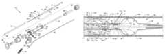
- FIG. 1is a plan view of the visible components of a rheolytic thrombectomy catheter
- FIG. 2is an isometric exploded and segmented view of the rheolytic thrombectomy catheter
- FIG. 3is an assembled view, in partial cross section, of the components of the manifold and closely associated components and features thereof, including a guidewire;
- FIG. 4is a partial cross section of the catheter distal section and a portion of the catheter proximal section
- FIG. 5is an isometric view of the fluid jet emanator shown connected to and in communication with a high pressure tube;
- FIG. 6illustrates the device as connected to ancillary devices for use
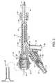
- FIG. 7is a side view, in partial cross section, of the rheolytic thrombectomy catheter in the performance of the method and use thereof;
- FIG. 8a first alternative embodiment, is an illustration similar in many respects to FIG. 2 showing a rheolytic thrombectomy catheter having an inflow orifice in lieu of the inflow gap of the first embodiment;
- FIG. 9is an illustration similar in many respects to FIG. 4 showing the distal end of the rheolytic thrombectomy catheter and the arrangement of a single inflow orifice in relation to the self-inflating balloon, to the fluid jet emanator, and to the balloon inflow inflation orifice;
- FIG. 10a second alternative embodiment, is an illustration similar in many respects to FIG. 8 showing a rheolytic thrombectomy catheter;
- FIG. 11is an illustration similar in many respects to FIG. 9 showing the distal end of the rheolytic thrombectomy catheter and the arrangement and relationship of the balloon inflation inflow orifice, the inflow orifice, the added outflow orifice, the fluid jet emanator, and the self-inflating balloon to each other;
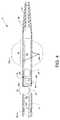
- FIG. 12is an illustration similar in many respects to FIG. 7 showing the operation of the rheolytic thrombectomy catheter in the performance of the method and use thereof;
- FIG. 13a third alternative embodiment, is an illustration similar in many respects to FIG. 8 showing a rheolytic thrombectomy catheter;
- FIG. 14is an illustration similar in many respects to FIG. 5 showing an alternative fluid jet emanator
- FIG. 15is an illustration similar in many respects to FIG. 9 showing the distal end of the rheolytic thrombectomy catheter and the arrangement of the inflow orifice and the arrangement of the jet orifices of the fluid jet emanator and the arrangement of the balloon inflation inflow orifice in relation to the self-inflating balloon; and,
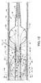
- FIG. 16is an illustration closely related to FIGS. 7 and 12 showing the rheolytic thrombectomy catheter in the performance of the method and use thereof.
- FIG. 1is a plan view of the visible components of rheolytic thrombectomy catheter 10 .
- the deviceincludes a one-piece manifold 12 having multiple structures extending therefrom or attached thereto, and also includes a flexible catheter tube 14 , preferably constructed of one or more sections of Pebax® material, and other components associated therewith as described herein.
- the visible portion of the one-piece manifold 12includes a central tubular body 16 (e.g., central elongated tubular body), a threaded exhaust branch 18 and a high pressure connection branch 20 extending angularly from central tubular body 16 , a partially shown cavity body 22 extending proximally from central tubular body 16 and a threaded connection port 24 extending distally from central tubular body 16 .
- the proximal end of catheter tube 14is secured to manifold 12 by the use of a Luer fitting 26 accommodated by threaded connection port 24 .
- the proximal end of catheter tube 14extends through a strain relief tube 28 and through Luer fitting 26 to communicate with manifold 12 .
- hemostasis nut 30in alignment with and threadingly engaged with the proximal region of cavity body 22 .
- a threaded high pressure connection port 32is secured to high pressure connection branch 20 by a Luer connector 34 .
- An introducer 36is also shown.
- Catheter tube 14extends distally and is interrupted by an annular inflow gap 38 between the proximal and distal sections of catheter tube 14 .
- the proximal section of catheter tube 14is that section which is proximal to inflow gap 38 .
- the distal section of catheter tube 14i.e., that part of which is distal to inflow gap 38 , includes a self-inflating balloon 40 (shown as an inflated balloon 40 a by dashed lines) which is integral to the distal section of catheter tube 14 .
- a tapered flexible tip 42extends distally from the distal section of catheter tube 14 and is secured thereto.
- a fluid jet emanator 52not shown in FIG. 1 but shown in FIGS.
- catheter tube 14is located distal to inflow gap 38 inside of the distal section of catheter tube 14 .
- a balloon inflation inflow orifice 44is located at and extends through the proximal portion of the distal section of catheter tube 14 .
- the proximal section of catheter tube 14functions as an exhaust tube for the evacuation of macerated effluence, thrombus, fluids or other debris from the site of a thrombus or lesion.
- catheter tube 14includes a hydrophilic coating to enhance deliverability along the vasculature or other structure.
- Catheter tube 14is made from a flexible plastic material such as Pebax® or another suitable flexible material.
- FIG. 2is an isometric exploded and segmented view of rheolytic thrombectomy catheter 10
- FIG. 3is an assembled view, in partial cross section, of the components of manifold 12 and closely associated components and features thereof, including a guidewire 46 such as is incorporated in the use of devices of the present disclosure.
- a collection of assembled componentsincluding a high pressure tube 50 and a fluid jet emanator 52 , deliver a high pressure saline or other suitable fluid to the distal section of catheter tube 14 for creation of high velocity fluid jet streams which are directed both proximally and distally from fluid jet emanator 52 , as later described in detail.
- High pressure tube 50preferably of flexible stainless steel or other suitable material, originates within closely associated features or components attached to manifold 12 and passes through and is generally distal to strain relief tube 28 and extends along a greater portion of and within lumen 82 of catheter tube 14 to terminate at fluid jet emanator 52 .
- the distal end of high pressure tube 50including fluid jet emanator 52 , is also shown in greater detail in FIGS. 4 and 5 .
- manifold 12has connected and communicating passageways and cavities ( FIG. 3 ) including a high pressure connection branch passageway 54 , an exhaust branch passageway 56 , a tapered central passageway 58 extending from and through threaded connection port 24 and through central tubular body 16 to and communicating with a multiple radius cavity 60 , which preferably is cylindrical and located central to cavity body 22 .
- External threads 62are located about the proximal portion of cavity body 22 at the proximal region of manifold 12 for accommodating of internal threads 64 of hemostasis nut 30 .
- Beneficial to the devices of the present disclosureis the use of a flexible self-sealing hemostasis valve 66 , and the use of a washer 68 which is located distal to self-sealing hemostasis valve 66 , the shapes and functions of which are described in the referenced U.S. Pat. No. 7,226,433.
- Self-sealing hemostasis valve 66 and washer 68are aligned in and housed within the greater radius portion of the multiple radius cavity 60 of cavity body 22 .
- Hemostasis nut 30includes a centrally located cylindrical boss 70 .
- Washer 68 and self-sealing hemostasis valve 66are captured within the greater radius portion of multiple radius cavity 60 by threaded engagement of hemostasis nut 30 to threads 62 at the proximal end of manifold 12 .
- Cylindrical boss 70is brought to bear against the collective self-sealing hemostasis valve 66 and washer 68 bringing pressure to bear, as required, against self-sealing hemostasis valve 66 , which pressure culminates in a forcible sealing of self-sealing hemostasis valve 66 about guidewire 46 .
- ferrule 76which is aligned within a passageway 78 of threaded high pressure connection port 32 , the combination of which is partially aligned within an interior passageway 80 of Luer connector 34 .
- the proximal end of flexible high pressure tube 50e.g., elongated flexible high pressure tube
- flexible high pressure tube 50shown in segmented form in FIG. 2
- ferrule 76can be utilized for the delivery of high pressure ablation liquids or for the delivery of drugs or other liquids and is suitably secured in a central passageway of ferrule 76 to communicate with interior passageway 78 of threaded high pressure connection port 32 , as shown in FIG. 3 .
- the threaded high pressure connection port 32serving as a fluid source for the flexible high pressure tube 50 , wherein the port 32 is connected with a saline reservoir or injection system.
- the proximal end of high pressure tube 50also extends through the high pressure connection branch passageway 54 , through part of tapered central passageway 58 , through strain relief tube 28 and Luer fitting 26 , and through a lumen 82 of catheter tube 14 .
- high pressure tube 50extends through support ring 84 and is suitably connected thereto to provide an anchoring and alignment structure for high pressure tube 50 in order to affix the distal portion of high pressure tube 50 at the proximal end of the distal section of catheter tube 14 .
- high pressure tube 50also extends through radiopaque marker band 88 .
- the concentrically aligned radiopaque marker band 88 and support ring 84are shown forcibly contacting the full wall thickness of catheter tube 14 adjacent the distal end of the proximal section of catheter tube 14 .
- High pressure tube 50preferably is attached to support ring 84 , such as by welding or other suitable means, where support ring 84 functions as a support for catheter tube 14 in the region beneath radiopaque marker band 88 .
- a short distal section of high pressure tube 50extends across inflow gap 38 and terminates within an internal annular manifold (not shown) of fluid jet emanator 52 and is suitably attached thereto where fluid jet emanator 52 communicates with the lumen of high pressure tube 50 , such as in the closely related fluid jet emanator described in the previously referenced patent application Ser. No. 11/096,592 or other applications or patents assigned to the assignee. Fluid jet emanator 52 , also shown in FIG.
- FIG. 5as an isometric view, includes an annular groove 94 which is in coordinated use with a radiopaque marker band 92 on catheter tube 14 to secure fluid jet emanator 52 within the proximal end of the distal section of catheter tube 14 (see FIG. 4 ).
- Other designs for fluid jet emanator, 52such as those disclosed in U.S. Pat. Nos. 5,370,609 and 6,676,637, both of which are incorporated herein by reference, can also be utilized with the devices of the present disclosure, along with other designs and securitization methods described in the literature by the assignee of the present disclosure.
- the distally located radiopaque marker band 92is forcibly applied around the proximal end of the distal section of catheter tube 14 to cause a frictional annular engagement with all or part of an annular groove 94 of the fluid jet emanator 52 .
- Such frictional engagementis sufficient to place the outer radial surface of both radiopaque marker bands 92 and 88 in a position lesser than the general and greater outer radial surface of catheter tube 14 , thereby providing, in part, a catheter tube 14 having no elements protruding beyond the general outer radial surface thereof for an unimpeded and smooth distal or proximal transition of catheter tube 14 within a vein, artery or the like.
- a passageway 98( FIG.
- tapeered flexible tip 42is shown in FIG. 4 suitably secured to the distal end of the distal section of catheter tube 14 .
- Tapered flexible tip 42includes a multiple radius inner passageway 96 for the accommodation of a guidewire 46 .
- radiopaque marker band 88is shown displaced a short distance distal to support ring 84 and fluid jet emanator 52 is shown displaced proximally a short distance from radiopaque marker band 92 for the purpose of clarity, but are shown in frictional engagement in their actual positions along and with respect to the distal section of catheter tube 14 in FIG. 4 .
- radiopaque marker bands 88 and 92 , support ring 84 , and fluid jet emanator 52 , respectively, to each other and to catheter tube 14are shown best in FIG. 4 .
- self-inflating balloon 40is shown contiguous with the distal section of catheter tube 14 , wherein self-inflating balloon 40 has a reduced wall thickness 14 a when compared to the general wall thickness of catheter tube 14 .
- the reduced wall thickness 14 a of self-inflating balloon 40is of a suitable thickness in order to allow the inflation of self-inflating balloon 40 to thereby expand, meet and align against the wall of the vasculature or against the thrombus, whereby a thrombectomy procedure, drug delivery procedure or other procedure can take place.
- self-inflating balloon 40can range in length from 2 mm to 200 mm.
- the central diameter of self-inflating balloon 40can range from 2 mm to 20 mm.
- Inflated balloon 40 acan be expanded, as desired, with an internal pressure up to 20 ATM.
- Expansion of self-inflating balloon 40is shown by dashed lines 40 a .
- reduced wall thickness 14 a of self-inflating balloon 40can be formed from other materials, as known in the art, and then bonded or extruded to catheter tube 14 to maintain a continuous structure throughout the length of catheter tube 14 (e.g., in the examples described herein and shown in the drawings the elongate flexible catheter tube 14 is substantially continuous from the proximal section through the elongated distal section containing the self-inflating balloon 40 therein).
- Tapered flexible tip 42as opposed to a rounded and nontapered flexible tip, can part and more easily penetrate thrombotic deposits or lesions during its insertional travel in a distal direction instead of advancing or pushing such thrombotic deposits or lesions distally.
- the decreasing diameter in a distal direction of tapered flexible tip 42also allows for an increased flexibility in negotiating and passing through tortuous paths.
- Exhaust tube support ring 84 in combination with radiopaque marker band 88 and fluid jet emanator 52 within and about the proximal and distal sections of catheter tube 14 , respectively,are examples of structures offering support or reinforcement along catheter tube 14 .
- Such a support ring 84 , marker bands 88 and 92 , and the external structure of fluid jet emanator 52provide for the use of a thinner wall thickness for catheter tube 14 and allow for a larger and more effective and efficiently sized lumen 82 of catheter tube 14 , as well as contributing to a reduced sized outer diameter.
- Such support rings and external structure of fluid jet emanator 52also contribute to supportively maintain the diameter and overall shape of catheter tube 14 when catheter tube 14 is pushed or advanced along a vein or vessel, as well as aiding in torsional support.
- FIG. 5is an isometric view of fluid jet emanator 52 shown connected to and in communication with high pressure tube 50 .
- Fluid jet emanator 52includes the previously described annular groove 94 and passageway 98 as well as a plurality of forwardly (distally) directed orifices 100 a - 100 n and a plurality of rearwardly (proximally) directed orifices 101 a - 101 n in parallel to the longitudinal axis of fluid jet emanator 52 .
- high pressure tube 50delivers a high pressure saline or other suitable fluid to fluid jet emanator 52 for the creation and distribution of high velocity fluid jet streams 102 of saline or other suitable fluids which are directed distally from the orifices 100 a - 100 n of fluid jet emanator 52 to perform functions as described herein.
- Fluid jet emanator 52also creates and distributes high velocity fluid jet streams 103 of saline or other suitable fluids which are directed proximally from orifices 101 a - 101 n to perform functions as described herein.
- fluid jet emanator 52Although the use of the particular style of fluid jet emanator 52 is shown, other fluid jet emanators having other configurations emanating high velocity fluid jet streams 102 and 103 can also be used in lieu of fluid jet emanator 52 and the use of other fluid jet emanators shall not be considered to be limiting to the scope of the present disclosure.
- a normal guidewireis deployed in a vessel requiring treatment or, in the alternative, a filter guidewire or balloon occlusion guidewire could also be used.
- Distally located components of the rheolytic thrombectomy catheter 10consisting mainly of catheter tube 14 , high pressure tube 50 , fluid jet emanator 52 , the distal section of catheter tube 14 , and uninflated balloon 40 and other components directly associated therewith, are advanced over and/or along a guidewire in the vasculature for the purpose of debris/thrombus removal, drug infusion, or other procedures and maneuvered into the appropriate position for treatment.
- a guide catheter or sheathcan be incorporated as necessary to offer assistance in placing catheter tube 14 of the rheolytic thrombectomy catheter 10 within the desired location of the vasculature.
- Rheolytic thrombectomy catheter 10is then activated, wherein self-inflating balloon 40 is automatically and expandingly deployed reforming as an expanded balloon 40 a , and then thrombus, debris and the like are removed or drugs can be infused by a desired procedure.
- Self-inflating balloon 40can be alternately pressurized and depressurized, whereby rheolytic thrombectomy catheter 10 may be moved proximally or distally during the procedure to maximize the effect of the system.
- self-inflating balloon 40is generally deflated sufficiently under normal arterial pressure to be removed safely, or deflation can be aided with a manual syringe attached to an effluent line, or deflation can be aided by means of a roller pump. Further interventions can be executed as normal over the remaining guidewire or guidewire device.
- FIGS. 6 and 7illustrate the mode of operation, where FIG. 6 illustrates rheolytic thrombectomy catheter 10 connected to ancillary devices, and FIG. 7 illustrates the distal portion of rheolytic thrombectomy catheter 10 in the performance of the method and use of the devices of the present disclosure.
- the mode of operationis best understood by referring to FIGS. 6 and 7 along with the previously described figures.
- rheolytic thrombectomy catheter 10is shown engaged over and about a guidewire 46 , wherein guidewire 46 (described herein from the distal to proximal direction) slidably passes through passageway 96 of tapered flexible tip 42 , into and through lumen 82 of the distal section of catheter tube 14 , past balloon inflation inflow orifice 44 , followed by transiting passageway 98 of fluid jet emanator 52 , past inflow gap 38 , followed by transiting the distal end of lumen 82 at the proximal section of catheter tube 14 , strain relief tube 28 , tapered central passageway 58 ( FIG.
- a high pressure fluid source 104 and a high pressure fluid pump 106are connected to manifold 12 via threaded high pressure connection port 32 and connector 108 .
- the fluid sourcemay consist of saline, one or more drugs for attacking the thrombus, or a mixture of saline and one or more drugs.
- An exhaust regulator 110such as a roller pump or other suitable device, and collection chamber 112 are connected to threaded exhaust branch 18 by a connector 114 , as shown.
- FIG. 7is a side view, in partial cross section, of rheolytic thrombectomy catheter 10 in the performance of the method and use thereof with particular attention given to the distal section of catheter tube 14 , flexible tapered tip 42 , balloon inflation inflow orifice 44 , inflated balloon 40 a interposed between flexible tapered tip 42 and the balloon inflow orifice 44 , fluid jet emanator 52 , inflow gap 38 , and other closely associated components positioned in a blood vessel 116 containing thrombotic particulate and/or debris 118 .
- high pressure tube 50delivers a high pressure saline or other suitable fluid to fluid jet emanator 52 to produce and distribute high velocity fluid jet streams 102 of saline or other suitable fluids which are directed distally from the orifices 100 a - 100 n (FIG.
- fluid jet emanator 52within and along the distal section of catheter tube 14 in close proximity to balloon inflation inflow orifice 44 and thence within the confines of self-inflating balloon 40 resulting in inflated balloon 40 a for the purposes of, but not limited to, impeding fluid flow within blood vessel 116 to effect a stagnate flow in the thrombectomy region, to provide centering of the distal section of catheter tube 14 , and to accomplish thrombectomy functions as described herein.
- the high pressure saline, or other suitable fluidis delivered by high pressure tube 50 to fluid jet emanator 52 to produce and distribute high velocity fluid jet streams 103 of saline or other suitable fluids which are directed proximally from the orifices 101 a - 101 n ( FIG. 5 ) of fluid jet emanator 52 , and thence to transit and cross inflow gap 38 , and finally into the distal end of the proximal section of catheter tube 14 where other functions as described herein are performed.
- Self-inflating balloon 40is automatically and expandingly deployed to reform as an inflated balloon 40 a primarily by the pressure of pressurized distally directed high velocity fluid jet streams 102 emanating from the jet orifices 100 a - 100 n of fluid jet emanator 52 .
- Fluid entrainment inflow 99shown by the directed arrows in FIG. 7 of the first embodiment, as well as in the later described alternative embodiments, assists in the inflation of the self-inflating balloon. Pressurized inflation of inflated balloon 40 a or maintaining a state of inflation is also assisted by utilizing back pressure along the length of catheter tube 14 .
- An operational advantageis the utilization of the exhaust outflow and internal pressure which is created by high velocity fluid jet stream(s) 103 in combination with the restriction of the outflow, such as influenced by exhaust regulator 110 , to cause automatic expansion of balloon 40 which forcibly impinges and seals against the inner walls of blood vessel 116 .
- the reduced thickness of the material comprising balloon 40allows balloon 40 to expand sufficiently to become an inflated balloon 40 a restricted by impingement with the wall of blood vessel 116 .
- Inflation pressure and fluid flowscan be influenced by controlling of the input pressure fluid at high pressure fluid pump 106 and/or by controlling of the exhaust rate at exhaust regulator 110 .
- fluid jet emanatorsof appropriate size and/or configuration can be incorporated in lieu of fluid jet emanator 52 within the proximal end of the distal section of catheter tube 14 to emanate or emit one or more high velocity fluid jet streams 102 distally and to emanate or emit one or more high velocity fluid jet streams 103 proximally along or near the longitudinal axis of catheter tube 14 .
- Inflation of balloon 40 to form inflated balloon 40 apositions the peripheral circumference of inflated balloon 40 against the wall of blood vessel 116 in order to effect a fluid flow reduction or cessation within blood vessel 116 .
- Inflated balloon 40 ai.e., balloon 40
- Inflated balloon 40 aprovides uniform centering and positioning of the distal section of catheter tube 14 within blood vessel 116 , thereby providing substantially equal spacing between the wall of blood vessel 116 and inflow gap 38 for uniform access and clearance thereto and thereabout.
- Inflated balloon 40 aalso provides a spacing between blood vessel 116 and balloon inflation inflow orifice 44 in order to provide access and clearance to and about balloon inflation inflow orifice 44 .
- High velocity fluid jet streams 103provide a low pressure region at inflow gap 38 to ingest and entrain thrombotic particulate and/or debris 118 therethrough to impinge on, provide drag forces on, and break up or macerate thrombotic particulate and/or debris 118 . Then, by entrainment, these jet streams urge and carry along one or more particles of thrombotic particulate and/or debris 118 or lesion particulate along lumen 82 of catheter tube 14 . The entrainment of thrombotic particulate and/or debris 118 through inflow gap 38 is based on entrainment by high velocity fluid jet streams 103 .
- the outflow of fluid and thrombusis driven proximally through catheter tube 14 by an internal pressure which is produced by high velocity fluid jet streams 103 and the fluid entrained through inflow gap 38 .
- Cessation of fluid flow in a blood vessel or other conduitmaximizes the effect of rheolytic thrombectomy catheter 10 in terms of debris or tissue removal.
- Use of the devices of the present disclosurecan also provide for the performance of a modified embolectomy by breaking up clots as inflated balloon 40 a is moved through a blocked vessel or can be used to minimize any distal or proximal embolization.
- FIG. 8a first alternative embodiment, is an illustration similar in many respects to FIG. 2 showing a rheolytic thrombectomy catheter 10 a having an inflow orifice 120 in lieu of inflow gap 38 of the first embodiment where all numerals correspond to those elements previously described or as otherwise described herein.
- catheter tube 14is not interrupted by the use of inflow gap 38 and is characterized as having distal sections generally distal to fluid jet emanator 52 and proximal sections generally proximal to fluid jet emanator 52 .
- FIG. 9is an illustration similar in many respects to FIG.
- catheter tube 14extends across the former location of inflow gap 38 of the first embodiment and is continuous thereacross.
- Fluid jet emanator 52is secured in the manner previously described.
- the performance of the method and use thereofclosely parallels that of the preferred embodiment of FIG. 1 by utilizing enabling connections to the ancillary devices shown in FIG. 6 whereby inflow orifice 120 , instead of inflow gap 38 , is used.
- High velocity fluid jet streams 103 of saline or other suitable fluidsprovide a low pressure region at inflow orifice 120 to ingest and entrain thrombotic particulate and/or debris 118 .
- FIG. 10a second alternative embodiment, is an illustration similar in many respects to FIG. 8 showing a rheolytic thrombectomy catheter 10 b , where all numerals correspond to those elements previously described or as otherwise described herein.
- An additional feature of rheolytic thrombectomy catheter 10 bis an outflow orifice 122 located on the distal section of catheter tube 14 in a position proximal to inflow orifice 120 .
- the outflow orifice 122is smaller than the inflow orifice as shown, for instance, in FIGS. 10 and 11 .
- FIG. 11is an illustration similar in many respects to FIG. 9 showing the distal end of rheolytic thrombectomy catheter 10 b and the arrangement and relationship of balloon inflation inflow orifice 44 , inflow orifice(s) 120 , added outflow orifice 122 , fluid jet emanator 52 , and self-inflating balloon 40 to each other.
- reduced wall thickness 14 a of self-inflating balloon 40can be formed from other materials, as known in the art, and then bonded or extruded to catheter tube 14 to maintain a continuous structure throughout the length of catheter tube 14 .
- FIG. 12is an illustration similar in many respects to FIG. 7 showing the operation of rheolytic thrombectomy catheter 10 b in the performance of the method and use thereof which closely parallels that of the preferred embodiment of FIG. 1 by utilizing enabling connections to the ancillary devices shown in FIG. 6 .
- balloon inflation inflow orifice 44is oriented away from the viewer and one or more inflow orifices 120 and outflow orifices 122 are shown at the top and the bottom of catheter tube 14 .
- Shown in particularis a cross section view of the distal and proximal sections of catheter tube 14 including inflated balloon 40 a , flexible tapered tip 42 , and other closely associated components positioned in a blood vessel 116 , artery or the like at and having been positioned through the site of a thrombotic deposit or lesion 118 a .
- the distal portion of high pressure tube 50delivers a high pressure saline or other suitable fluid to fluid jet emanator 52 to produce and distribute high velocity fluid jet streams 102 of saline or other suitable fluids which are directed distally from orifices 100 a - 100 n of fluid jet emanator 52 within and along the distal section of catheter tube 14 in close proximity to balloon inflation inflow orifice 44 and thence within the confines of self-inflating balloon 40 to cause the inflation of inflated balloon 40 a for the purposes of, but not limited to, impeding fluid flow within blood vessel 116 to effect a stagnate flow in the thrombectomy region, to provide centering of the distal and proximal sections of catheter tube 14 and to accomplish thrombectomy functions as described herein.
- self-inflating balloon 40is automatically and expandingly deployed to reform as an inflated balloon 40 a primarily by the pressure of the pressurized distally directed high velocity fluid jet streams 102 of saline or other suitable fluid emanating from jet orifices 100 a - 100 n of fluid jet emanator 52 .
- Multiple high velocity fluid jet streams 103 of saline (or other suitable fluids)are emitted in a proximal direction from jet orifices 101 a - 101 n of fluid jet emanator 52 and pass outwardly through one or more of outflow orifice(s) 122 in a radial direction.
- This actionproduces high velocity cross stream jet(s) 124 a - 124 n directed outwardly toward the wall of blood vessel 116 and these jet(s) are influenced by the low pressure at inflow orifice(s) 120 to cause high velocity cross stream jet(s) 124 to flow distally and circumferentially to impinge on, provide drag forces on, and break up thrombotic deposits or lesions 118 a .
- the jet(s)urge and carry along the loosened thrombotic particulate and/or debris 118 (and/or lesions) through the inflow orifice(s) 120 , a relatively low pressure region, into the high velocity jet streams 103 where the thrombotic particulate and/or debris 118 (and/or lesions) is further macerated into microscopic particles, and thence into catheter tube lumen 82 , and finally through lumen 82 for subsequent exhausting.
- the exhaust outflowis driven by an internal pressure which is created by high velocity fluid jet stream(s) 103 and the fluid entrained through inflow orifice(s) 120 to cause pressurization within lumen 82 .
- An advantage provided by the distally located inflated balloon 40 ais that in a no-flow situation where the distal flow of blood is stopped by inflation of intervening inflated balloon 40 a , the particles of thrombotic particulate and/or debris 118 adjacent outflow orifice(s) 122 and inflow orifice(s) 120 are substantially trapped and can be more effectively circulated, recirculated and rediluted until all that remains is saline and minute particles of thrombotic particulate and/or debris 118 . These particles are subsequently removed in a proximal direction through lumen 82 of catheter tube 14 by promoting flow via exhaust regulator 110 .
- Another advantageis the utilization of the exhaust outflow and internal pressure which is created by high velocity fluid jet stream(s) 103 in combination with the restriction of the outflow, such as influenced by exhaust regulator 110 , to cause automatic expansion of balloon 40 which forcibly impinges and seals against the inner wall of blood vessel 116 .
- the reduced thickness of the material comprising balloon 40allows balloon 40 to expand sufficiently to become an inflated balloon 40 a which expansion is restricted by its impingement with the wall of blood vessel 116 .
- Inflation pressure and fluid flowscan be influenced by controlling the input fluid pressure at high pressure fluid pump 106 and by controlling the exhaust rate at exhaust regulator 110 .
- other fluid jet emanators of different structurescan be incorporated within the distal portion of catheter tube 14 as an alternative to jet emanator 52 to accomplish the same purpose as that described for fluid jet emanator 52 .
- FIG. 13a third alternative embodiment, is an illustration similar in many respects to FIG. 8 showing a rheolytic thrombectomy catheter 10 c , where all numerals correspond to those elements previously described or as otherwise described herein.
- An additional feature of rheolytic thrombectomy catheter 10 cis a fluid jet emanator 52 a corresponding in general design to that of fluid jet emanator 52 shown in FIG. 5 , but including features which provide for the emanation of outwardly directed high velocity fluid radial jets 125 a - 125 n therefrom, as shown in FIG. 14 .
- FIG. 14is an illustration similar in many respects to FIG. 5 showing a fluid jet emanator 52 a , where all numerals correspond to those elements previously described or as otherwise described herein.
- Additional uniformly aligned and spaced orifices 126 a - 126 nare arranged about the proximal peripheral circumference of fluid jet emanator 52 a and are in communication with an internal manifold (not shown) and with jet orifices 101 a - 101 n and provide for outwardly directed emanation of high velocity fluid radial jets 125 a - 125 n of saline or other suitable fluids therefrom.
- orientation of orifices 126 a - 126 ncan be randomly or otherwise angulated with respect to perpendicular orientation in order to provide high velocity fluid radial jets 125 a - 125 n at other than perpendicular emanation therefrom and directed as desired.
- FIG. 15is an illustration similar in many respects to FIG. 9 showing the distal end of rheolytic thrombectomy catheter 10 c and the arrangement of inflow orifice 120 and the arrangement of jet orifices 126 a - 126 n of fluid jet emanator 52 a and the arrangement of balloon inflation inflow orifice 44 in relation to self-inflating balloon 40 . Also shown is the plurality of holes 128 a - 128 n extending through the wall of the catheter tube 14 in corresponding alignment with jet orifices 126 a - 126 n . High velocity fluid radial jets 125 a - 125 n ( FIG. 14 ) emanate through jet orifices 126 a - 126 n and through the plurality of holes 128 a - 128 n in order to provide treatment, as shown and described in FIG. 16 .
- FIG. 16is an illustration closely related to FIG. 7 and FIG. 12 showing rheolytic thrombectomy catheter 10 b in the performance of the method and use thereof which closely parallels that of the preferred embodiment of FIG. 1 by utilizing enabling connections to the ancillary devices shown in FIG. 6 .
- balloon inflation inflow orifice 44is oriented away from the viewer and one or more inflow orifices 120 are shown at the top and the bottom of catheter tube 14 .
- radially directed high velocity fluid radial jets 125 a - 125 n from the radial jet orifices 126 a - 126 nprovides for impingement of thrombotic deposits or lesions 118 a on the inner wall of blood vessel 116 adjacent to the region of inflow orifice(s) 120 .
- This actionimpinges, ablates and loosens thrombotic deposits or lesions 118 a , whereby thrombotic particulate and/or debris 118 (and/or lesions) and fluids can be then entrained by high velocity fluid jet streams 103 of saline or other suitable fluids and exhausted proximally through catheter tube 14 .
- drugs for treatment or for lysing of thrombotic deposits or lesions 118 acan also be delivered via the radial jet orifices 126 a - 126 n and high velocity fluid radial jets 125 a - 125 n in order to soften the thrombotic deposits or lesions 118 a in the region adjacent to the inflow orifice(s) 120 , thereby benefiting and making use of high velocity fluid radial jets 125 a - 125 n more effective.
- the drugsare delivered through high pressure tube 50 to the sites of the thrombotic deposits or lesions 118 a using fluid jet emanator 52 a , or could be delivered by the fluid jet emanators 52 and closely associated components in the previous embodiments.
Landscapes
- Health & Medical Sciences (AREA)
- Surgery (AREA)
- Life Sciences & Earth Sciences (AREA)
- Biomedical Technology (AREA)
- Nuclear Medicine, Radiotherapy & Molecular Imaging (AREA)
- Engineering & Computer Science (AREA)
- Vascular Medicine (AREA)
- Heart & Thoracic Surgery (AREA)
- Medical Informatics (AREA)
- Molecular Biology (AREA)
- Animal Behavior & Ethology (AREA)
- General Health & Medical Sciences (AREA)
- Public Health (AREA)
- Veterinary Medicine (AREA)
- Surgical Instruments (AREA)
Abstract
Description
Claims (10)
Priority Applications (1)
| Application Number | Priority Date | Filing Date | Title |
|---|---|---|---|
| US12/336,750US8303538B2 (en) | 2007-12-17 | 2008-12-17 | Rheolytic thrombectomy catheter with self-inflating distal balloon |
Applications Claiming Priority (2)
| Application Number | Priority Date | Filing Date | Title |
|---|---|---|---|
| US785207P | 2007-12-17 | 2007-12-17 | |
| US12/336,750US8303538B2 (en) | 2007-12-17 | 2008-12-17 | Rheolytic thrombectomy catheter with self-inflating distal balloon |
Publications (2)
| Publication Number | Publication Date |
|---|---|
| US20090156983A1 US20090156983A1 (en) | 2009-06-18 |
| US8303538B2true US8303538B2 (en) | 2012-11-06 |
Family
ID=40754198
Family Applications (1)
| Application Number | Title | Priority Date | Filing Date |
|---|---|---|---|
| US12/336,750Active2031-03-31US8303538B2 (en) | 2007-12-17 | 2008-12-17 | Rheolytic thrombectomy catheter with self-inflating distal balloon |
Country Status (2)
| Country | Link |
|---|---|
| US (1) | US8303538B2 (en) |
| WO (1) | WO2009079539A1 (en) |
Cited By (4)
| Publication number | Priority date | Publication date | Assignee | Title |
|---|---|---|---|---|
| US20140257097A1 (en)* | 2013-03-11 | 2014-09-11 | Medrad, Inc. | Double action infusion pump |
| US10743907B2 (en) | 2014-11-07 | 2020-08-18 | National University Of Ireland, Galway | Thrombectomy device |
| US10779852B2 (en) | 2013-03-15 | 2020-09-22 | National University Of Ireland, Galway | Device suitable for removing matter from inside the lumen and the wall of a body lumen |
| US11679195B2 (en) | 2021-04-27 | 2023-06-20 | Contego Medical, Inc. | Thrombus aspiration system and methods for controlling blood loss |
Families Citing this family (10)
| Publication number | Priority date | Publication date | Assignee | Title |
|---|---|---|---|---|
| US20140277006A1 (en)* | 2013-03-14 | 2014-09-18 | Medrad, Inc. | Thrombectomy catheters, systems and methods |
| EP3035876B1 (en) | 2013-09-18 | 2018-11-14 | Xablecath Inc. | Device and system for crossing and treating an occlusion |
| WO2015061801A2 (en)* | 2013-10-26 | 2015-04-30 | Accumed Radial Systems Llc | System, apparatus, and method for creating a lumen |
| EP3182920B1 (en)* | 2014-08-21 | 2024-03-13 | Koninklijke Philips N.V. | Device for crossing occlusions |
| EP3258861A4 (en)* | 2015-02-18 | 2018-06-27 | Xablecath Inc. | Systems and methods for crossing and treating an occlusion |
| US20200078564A1 (en)* | 2018-09-10 | 2020-03-12 | Becton, Dickinson And Company | Peripheral intravenous catheter assembly having an extension set |
| US11602617B2 (en) | 2019-04-18 | 2023-03-14 | Michael Bonnette | Pumpless thrombectomy system |
| CN115916075A (en) | 2020-01-30 | 2023-04-04 | 尤利耶尔医疗股份公司 | Device and method for neurovascular endoluminal intervention |
| CN111184555B (en)* | 2020-03-19 | 2021-04-13 | 昆山金泰医疗科技有限公司 | Controllable liquid medicine injection thrombus removing device |
| US11737767B2 (en) | 2022-01-21 | 2023-08-29 | Julier Medical AG | Neurovascular catheter and method of use |
Citations (214)
| Publication number | Priority date | Publication date | Assignee | Title |
|---|---|---|---|---|
| US3435826A (en) | 1964-05-27 | 1969-04-01 | Edwards Lab Inc | Embolectomy catheter |
| US3695208A (en) | 1970-11-16 | 1972-10-03 | Ind Patent Dev Corp | Food storage apparatus for use in water-borne vessels |
| US3752617A (en) | 1969-10-13 | 1973-08-14 | Sherwood Medical Ind Inc | Apparatus for extruding products of plural components of varied proportions with scrap reclamation |
| US3833003A (en) | 1972-07-05 | 1974-09-03 | A Taricco | Intravascular occluding catheter |
| US3930505A (en) | 1974-06-24 | 1976-01-06 | Hydro Pulse Corporation | Surgical apparatus for removal of tissue |
| US4168709A (en) | 1975-03-10 | 1979-09-25 | Bentov Itzhak E | Dilator |
| GB1571459A (en) | 1977-12-20 | 1980-07-16 | Instavac Ltd | Vacuum pumps and vacuum pump assemblies |
| US4224943A (en) | 1979-01-24 | 1980-09-30 | Sorenson Research Co., Inc. | Cannula and method for bidirectional blood flow |
| US4248234A (en) | 1979-03-08 | 1981-02-03 | Critikon, Inc. | Catheter with variable flexural modulus and method of using same |
| US4290428A (en) | 1978-09-01 | 1981-09-22 | Durand Alain J M | Catheter with bulb |
| US4328811A (en) | 1980-07-28 | 1982-05-11 | Fogarty Thomas J | Calibrating dilation catheter |
| US4385635A (en) | 1980-04-25 | 1983-05-31 | Ruiz Oscar F | Angiographic catheter with soft tip end |
| US4515592A (en) | 1980-05-13 | 1985-05-07 | Arrow International, Inc. | Catheter shield |
| US4535757A (en) | 1982-03-12 | 1985-08-20 | Webster Wilton W Jr | Autoinflatable catheter |
| DE3421390C2 (en) | 1984-06-08 | 1986-07-17 | Werner Dr.med. 4330 Mülheim Schubert | High pressure catheter with cutting and / or abrasion device |
| US4610662A (en) | 1981-11-24 | 1986-09-09 | Schneider Medintag Ag | Method for the elimination or the enlargement of points of constriction in vessels carrying body fluids |
| US4631052A (en) | 1984-01-03 | 1986-12-23 | Intravascular Surgical Instruments, Inc. | Method and apparatus for surgically removing remote deposits |
| US4636346A (en) | 1984-03-08 | 1987-01-13 | Cordis Corporation | Preparing guiding catheter |
| US4690672A (en) | 1984-09-06 | 1987-09-01 | Veltrup Elmar M | Apparatus for removing solid structures from body passages |
| EP0251512A1 (en) | 1986-06-09 | 1988-01-07 | The Regents Of The University Of California | Apparatus for removing gallstones |
| US4739768A (en) | 1986-06-02 | 1988-04-26 | Target Therapeutics | Catheter for guide-wire tracking |
| US4747405A (en) | 1984-03-01 | 1988-05-31 | Vaser, Inc. | Angioplasty catheter |
| US4781186A (en) | 1984-05-30 | 1988-11-01 | Devices For Vascular Intervention, Inc. | Atherectomy device having a flexible housing |
| US4782834A (en) | 1987-01-06 | 1988-11-08 | Advanced Cardiovascular Systems, Inc. | Dual lumen dilatation catheter and method of manufacturing the same |
| US4790813A (en) | 1984-12-17 | 1988-12-13 | Intravascular Surgical Instruments, Inc. | Method and apparatus for surgically removing remote deposits |
| US4834710A (en) | 1987-10-08 | 1989-05-30 | Arrow International Investment Corporation | Catheter shield and test structure |
| US4842579A (en) | 1984-05-14 | 1989-06-27 | Surgical Systems & Instruments, Inc. | Atherectomy device |
| US4883459A (en) | 1983-07-29 | 1989-11-28 | Reynaldo Calderon | Retrograde perfusion |
| US4888146A (en) | 1988-05-19 | 1989-12-19 | Dandeneau James V | Method and apparatus of forming extruded article |
| US4898574A (en) | 1986-05-08 | 1990-02-06 | Olympus Optical Co., Ltd. | Lithotomic apparatus |
| US4898591A (en) | 1988-08-09 | 1990-02-06 | Mallinckrodt, Inc. | Nylon-PEBA copolymer catheter |
| US4902276A (en) | 1986-06-09 | 1990-02-20 | The Regents Of The University Of California | Apparatus and method for removing obstructions in bodily organs or cavities |
| US4913698A (en) | 1987-10-26 | 1990-04-03 | Marui Ika Company, Limited | Aqua-stream and aspirator for brain surgery |
| US4917667A (en) | 1988-02-11 | 1990-04-17 | Retroperfusion Systems, Inc. | Retroperfusion balloon catheter and method |
| WO1990005493A1 (en) | 1988-11-15 | 1990-05-31 | Svedman Paal | Surgical instrument |
| US4950238A (en) | 1988-07-07 | 1990-08-21 | Clarence E. Sikes | Hydro-rotary vascular catheter |
| US5011469A (en) | 1988-08-29 | 1991-04-30 | Shiley, Inc. | Peripheral cardiopulmonary bypass and coronary reperfusion system |
| US5015232A (en) | 1989-04-20 | 1991-05-14 | Cook Incorporated | Decompression enteroclysis balloon catheter |
| US5042976A (en) | 1987-01-13 | 1991-08-27 | Terumo Kabushiki Kaisha | Balloon catheter and manufacturing method of the same |
| US5085649A (en) | 1990-11-21 | 1992-02-04 | Flynn Vincent J | Torque controlled tubing |
| US5085549A (en) | 1990-12-24 | 1992-02-04 | Ford Motor Company | Three-axis variability compensating fastener |
| US5085635A (en) | 1990-05-18 | 1992-02-04 | Cragg Andrew H | Valved-tip angiographic catheter |
| US5086842A (en) | 1989-09-07 | 1992-02-11 | Institut Francais Du Petrole | Device and installation for the cleaning of drains, particularly in a petroleum production well |
| US5090960A (en) | 1990-01-12 | 1992-02-25 | Don Michael T Anthony | Regional perfusion dissolution catheter |
| US5092873A (en) | 1990-02-28 | 1992-03-03 | Devices For Vascular Intervention, Inc. | Balloon configuration for atherectomy catheter |
| US5114399A (en) | 1990-10-01 | 1992-05-19 | Intramed Laboratories | Surgical device |
| US5135482A (en) | 1985-12-31 | 1992-08-04 | Arnold Neracher | Hydrodynamic device for the elimination of an organic deposit obstructing a vessel of a human body |
| US5163431A (en) | 1990-04-09 | 1992-11-17 | Cordis Corporation | Angiographic catheter |
| US5171221A (en) | 1991-02-05 | 1992-12-15 | Target Therapeutics | Single lumen low profile valved balloon catheter |
| EP0528181A1 (en) | 1991-08-21 | 1993-02-24 | Mitsubishi Cable Industries, Ltd. | Process and apparatus for producing elongated body elastic modulus changing type |
| US5215614A (en) | 1989-06-29 | 1993-06-01 | Cordis Europa N.V. | Method for manufacturing a catheter |
| US5221270A (en) | 1991-06-28 | 1993-06-22 | Cook Incorporated | Soft tip guiding catheter |
| US5222941A (en) | 1990-01-12 | 1993-06-29 | Don Michael T Anthony | Method of dissolving an obstruction in a vessel |
| US5234416A (en) | 1991-06-06 | 1993-08-10 | Advanced Cardiovascular Systems, Inc. | Intravascular catheter with a nontraumatic distal tip |
| US5250059A (en) | 1992-01-22 | 1993-10-05 | Devices For Vascular Intervention, Inc. | Atherectomy catheter having flexible nose cone |
| US5250034A (en) | 1990-09-17 | 1993-10-05 | E-Z-Em, Inc. | Pressure responsive valve catheter |
| US5254107A (en) | 1991-03-06 | 1993-10-19 | Cordis Corporation | Catheter having extended braid reinforced transitional tip |
| US5259842A (en) | 1992-01-25 | 1993-11-09 | Hp-Media Gesellschaft Mgh Fur Medizintechnische Systeme | High-pressure liquid dispenser for the dispensing of sterile liquid |
| US5267979A (en) | 1990-09-17 | 1993-12-07 | E-Z-Em, Inc. | Pressure responsive valve catheter |
| US5273526A (en) | 1991-06-21 | 1993-12-28 | Lake Region Manufacturing Company, Inc. | Vascular occulusion removal devices and method |
| US5300022A (en) | 1992-11-12 | 1994-04-05 | Martin Klapper | Urinary catheter and bladder irrigation system |
| US5306249A (en) | 1990-01-12 | 1994-04-26 | Don Michel T Anthony | Method of treating body passage walls |
| US5308342A (en) | 1991-08-07 | 1994-05-03 | Target Therapeutics, Inc. | Variable stiffness catheter |
| WO1994010917A1 (en) | 1992-11-13 | 1994-05-26 | Drasler William J | Thrombectomy and tissue removal method and device |
| USRE34633E (en) | 1987-11-13 | 1994-06-07 | Cook Incorporated | Balloon guide |
| US5318518A (en) | 1991-08-14 | 1994-06-07 | Hp Medica Gesellschaft Mbh Fur Medizintechnische Systeme | Irrigating catheter |
| US5320599A (en) | 1990-02-14 | 1994-06-14 | Cordis Corporation | Drainage catheter |
| US5324285A (en) | 1989-04-28 | 1994-06-28 | C.B.A. Moulin De Classe | Laser-catheter |
| US5331679A (en) | 1991-12-09 | 1994-07-19 | Kabushiki Kaisha Toshiba | Fuel spacer for fuel assembly |
| US5342386A (en) | 1992-10-26 | 1994-08-30 | Cordis Corporation | Catheter with multiple flexibilities along the shaft |
| US5356388A (en) | 1992-09-22 | 1994-10-18 | Target Therapeutics, Inc. | Perfusion catheter system |
| US5358485A (en) | 1992-01-13 | 1994-10-25 | Schneider (Usa) Inc. | Cutter for atherectomy catheter |
| US5360379A (en) | 1993-10-25 | 1994-11-01 | Alliedsignal Inc. | Packaging machinery belt with non-directional splice |
| US5370609A (en) | 1990-08-06 | 1994-12-06 | Possis Medical, Inc. | Thrombectomy device |
| US5372601A (en) | 1993-03-30 | 1994-12-13 | Lary; Banning G. | Longitudinal reciprocating incisor |
| US5380307A (en) | 1992-09-30 | 1995-01-10 | Target Therapeutics, Inc. | Catheter with atraumatic drug delivery tip |
| US5385548A (en) | 1993-04-22 | 1995-01-31 | Dlp, Inc. | Balloon catheter for retrograde perfusion |
| US5399164A (en) | 1992-11-02 | 1995-03-21 | Catheter Imaging Systems | Catheter having a multiple durometer |
| WO1995010232A1 (en) | 1993-10-08 | 1995-04-20 | Lake Region Manufacturing Company, Inc. | Rheolytic occlusion removal catheter system and method |
| US5409454A (en) | 1991-02-19 | 1995-04-25 | Arrow International Investment Corp. | Apparatus for atherectomy |
| US5425723A (en) | 1993-12-30 | 1995-06-20 | Boston Scientific Corporation | Infusion catheter with uniform distribution of fluids |
| US5456665A (en) | 1994-03-04 | 1995-10-10 | Arrow International Investment Corp. | Intra-aortic balloon catheter |
| US5456674A (en) | 1993-03-31 | 1995-10-10 | Cordis Corporation | Catheters with variable properties |
| US5478330A (en) | 1992-12-01 | 1995-12-26 | Cardiac Pathways Corporation | Steerable catheter with adjustable bend location and/or radius and method |
| US5492532A (en) | 1989-03-17 | 1996-02-20 | B. Braun Medical, Inc. | Balloon catheter |
| US5496294A (en) | 1994-07-08 | 1996-03-05 | Target Therapeutics, Inc. | Catheter with kink-resistant distal tip |
| US5496267A (en) | 1990-11-08 | 1996-03-05 | Possis Medical, Inc. | Asymmetric water jet atherectomy |
| US5499973A (en) | 1994-09-08 | 1996-03-19 | Saab; Mark A. | Variable stiffness balloon dilatation catheters |
| US5514092A (en) | 1994-08-08 | 1996-05-07 | Schneider (Usa) Inc. | Drug delivery and dilatation-drug delivery catheters in a rapid exchange configuration |
| US5513956A (en) | 1994-01-14 | 1996-05-07 | Arrow International Investment Corp. | Circulatory assisted device with motor driven gas pump |
| US5531685A (en) | 1993-06-11 | 1996-07-02 | Catheter Research, Inc. | Steerable variable stiffness device |
| US5531679A (en) | 1994-03-14 | 1996-07-02 | Schulman; Joseph H. | Fluidic infusion system for catheter or probe |
| US5536242A (en) | 1994-07-01 | 1996-07-16 | Scimed Life Systems, Inc. | Intravascular device utilizing fluid to extract occlusive material |
| US5554121A (en) | 1994-07-25 | 1996-09-10 | Advanced Cardiovascular Systems, Inc. | Intraluminal catheter with high strength proximal shaft |
| US5558642A (en) | 1991-08-02 | 1996-09-24 | Scimed Life Systems, Inc. | Drug delivery catheter |
| US5571094A (en) | 1992-01-09 | 1996-11-05 | Advanced Cardiovascular Systems, Inc. | Guidewire replacement device |
| US5599325A (en) | 1994-05-18 | 1997-02-04 | Schneider (Usa) Inc | Thin wall catheter with reinforcing sleeve |
| US5599299A (en) | 1992-05-11 | 1997-02-04 | Arrow Precision Products, Inc. | Multi-lumen endoscopic catheter |
| US5609574A (en) | 1992-11-02 | 1997-03-11 | Localmed, Inc. | Intravascular catheter with infusion array |
| US5628730A (en) | 1990-06-15 | 1997-05-13 | Cortrak Medical, Inc. | Phoretic balloon catheter with hydrogel coating |
| US5643279A (en) | 1996-03-12 | 1997-07-01 | Cordis Corporation | Method of catheter balloon manufacture and use |
| US5658263A (en) | 1995-05-18 | 1997-08-19 | Cordis Corporation | Multisegmented guiding catheter for use in medical catheter systems |
| US5662608A (en) | 1995-07-26 | 1997-09-02 | Intelliwire, Inc. | Low profile balloon catheter and method |
| US5662622A (en) | 1995-04-04 | 1997-09-02 | Cordis Corporation | Intravascular catheter |
| US5668702A (en) | 1994-04-21 | 1997-09-16 | Nassimi; Shary | Combination axial and surface mount cylindrical package containing one or more electronic components |
| US5676659A (en) | 1993-11-12 | 1997-10-14 | Medtronic, Inc. | Small diameter, high torque catheter |
| US5681336A (en) | 1995-09-07 | 1997-10-28 | Boston Scientific Corporation | Therapeutic device for treating vien graft lesions |
| US5683345A (en) | 1994-10-27 | 1997-11-04 | Novoste Corporation | Method and apparatus for treating a desired area in the vascular system of a patient |
| US5687714A (en) | 1995-10-10 | 1997-11-18 | The United States Of America As Represented By The Department Of Health And Human Services | Self-cleaning endotracheal tube apparatus |
| US5702439A (en) | 1990-08-28 | 1997-12-30 | Scimed Life Systems, Inc. | Balloon catheter with distal guide wire lumen |
| US5704926A (en) | 1994-11-23 | 1998-01-06 | Navarre Biomedical, Ltd. | Flexible catheter |
| US5713849A (en) | 1994-07-19 | 1998-02-03 | Cordis Corporation | Suction catheter and method |
| US5769828A (en) | 1996-06-13 | 1998-06-23 | Medtronic, Inc. | Two-stage venous cannula with expandable reinforcing member |
| US5792167A (en) | 1996-09-13 | 1998-08-11 | Stryker Corporation | Surgical irrigation pump and tool system |
| US5795325A (en) | 1991-07-16 | 1998-08-18 | Heartport, Inc. | Methods and apparatus for anchoring an occluding member |
| US5795322A (en) | 1995-04-10 | 1998-08-18 | Cordis Corporation | Catheter with filter and thrombus-discharge device |
| US5817046A (en) | 1997-07-14 | 1998-10-06 | Delcath Systems, Inc. | Apparatus and method for isolated pelvic perfusion |
| US5843022A (en) | 1995-10-25 | 1998-12-01 | Scimied Life Systems, Inc. | Intravascular device utilizing fluid to extract occlusive material |
| US5900444A (en) | 1996-10-08 | 1999-05-04 | Zamore; Alan | Irradiation conversion of thermoplastic to thermoset polyurethane |
| US5906590A (en) | 1995-05-22 | 1999-05-25 | Ep Technologies, Inc. | Bidirectional steerable catheter with deflectable distal tip |
| US5919163A (en) | 1997-07-14 | 1999-07-06 | Delcath Systems, Inc. | Catheter with slidable balloon |
| US5928181A (en) | 1997-11-21 | 1999-07-27 | Advanced International Technologies, Inc. | Cardiac bypass catheter system and method of use |
| US5929633A (en) | 1996-11-29 | 1999-07-27 | Fischer; Helmut | Device for measuring the thickness of thin layers |
| US5935501A (en) | 1994-03-18 | 1999-08-10 | Arrow International, Inc. | Method for making a packaging sheath for intra-aortic balloon catheters |
| US5939320A (en) | 1996-05-20 | 1999-08-17 | New York University | G-coupled receptors associated with macrophage-trophic HIV, and diagnostic and therapeutic uses thereof |
| US5944686A (en) | 1995-06-07 | 1999-08-31 | Hydrocision, Inc. | Instrument for creating a fluid jet |
| US5951513A (en) | 1995-02-24 | 1999-09-14 | Advanced Cardiovascular Systems, Inc. | Balloon catheter having non-bonded integral balloon and methods for its manufacture |
| US5957901A (en) | 1997-10-14 | 1999-09-28 | Merit Medical Systems, Inc. | Catheter with improved spray pattern for pharmaco-mechanical thrombolysis therapy |
| US5989210A (en) | 1998-02-06 | 1999-11-23 | Possis Medical, Inc. | Rheolytic thrombectomy catheter and method of using same |
| US5989271A (en) | 1998-11-09 | 1999-11-23 | Possis Medical, Inc. | Flexible tip rheolytic thrombectomy catheter and method of constructing same |
| US6001078A (en) | 1996-05-29 | 1999-12-14 | Cordis Corporation | Selective positioning drainage catheter |
| US6004269A (en) | 1993-07-01 | 1999-12-21 | Boston Scientific Corporation | Catheters for imaging, sensing electrical potentials, and ablating tissue |
| US6004339A (en) | 1996-11-13 | 1999-12-21 | Angiodynamics Incorporated | Balloon catheter with multiple distensibilities |
| US6022336A (en) | 1996-05-20 | 2000-02-08 | Percusurge, Inc. | Catheter system for emboli containment |
| US6024729A (en) | 1998-03-10 | 2000-02-15 | Vernay Laboratories, Inc. | Hemostasis valve assembly including guide wire seal |
| US6027499A (en) | 1997-05-23 | 2000-02-22 | Fiber-Tech Medical, Inc. (Assignee Of Jennifer B. Cartledge) | Method and apparatus for cryogenic spray ablation of gastrointestinal mucosa |
| US6044845A (en) | 1998-02-03 | 2000-04-04 | Salient Interventional Systems, Inc. | Methods and systems for treating ischemia |
| US6062623A (en) | 1998-05-18 | 2000-05-16 | Prince Corporation | Latch for vehicle overhead storage bin |
| US6063069A (en) | 1997-05-19 | 2000-05-16 | Micro Therapeutics Inc. | Method and apparatus for power lysis of a thrombus |
| US6068623A (en) | 1997-03-06 | 2000-05-30 | Percusurge, Inc. | Hollow medical wires and methods of constructing same |
| US6074374A (en) | 1998-07-31 | 2000-06-13 | Angiodynamics, Inc. | Catheter with lumen occluding means |
| US6099496A (en) | 1998-09-30 | 2000-08-08 | Medtronic Ave, Inc. | Catheter having a variable length shaft segment and method of use |
| US6106642A (en) | 1998-02-19 | 2000-08-22 | Boston Scientific Limited | Process for the improved ductility of nitinol |
| US6129698A (en) | 1996-05-24 | 2000-10-10 | Beck; Robert C | Catheter |
| US6129697A (en) | 1990-08-06 | 2000-10-10 | Possis Medical, Inc. | Thrombectomy and tissue removal device |
| US6135977A (en) | 1994-02-16 | 2000-10-24 | Possis Medical, Inc. | Rheolytic catheter |
| US6165199A (en) | 1999-01-12 | 2000-12-26 | Coaxia, Inc. | Medical device for removing thromboembolic material from cerebral arteries and methods of use |
| USRE37153E1 (en) | 1992-10-13 | 2001-05-01 | Sentry Equipment Corp. | Variable pressure reducing device |
| US6224570B1 (en) | 1998-02-06 | 2001-05-01 | Possis Medical, Inc. | Rheolytic thrombectomy catheter and method of using same |
| US6241744B1 (en) | 1998-08-14 | 2001-06-05 | Fox Hollow Technologies, Inc. | Apparatus for deploying a guidewire across a complex lesion |
| US6273880B1 (en) | 1998-01-21 | 2001-08-14 | St. Jude Medical Anastomotic Technology Group, Inc. | Catheters with integrated lumen and methods of their manufacture and use |
| US6283950B1 (en) | 1998-06-11 | 2001-09-04 | Angiodynamics, Inc. | Occluding wire assembly |
| US20010051785A1 (en) | 1990-08-06 | 2001-12-13 | Possis Medical, Inc. | Thrombectomy catheter and system |
| US6331176B1 (en) | 1999-03-11 | 2001-12-18 | Advanced Cardiovascular Systems, Inc. | Bleed back control assembly and method |
| US20010053920A1 (en) | 2000-03-27 | 2001-12-20 | Wilson-Cook Medical Inc. | Apparatus for measuring esophageal sphincter compliance |
| US20020032408A1 (en) | 2000-07-14 | 2002-03-14 | Cook Incorporated | Medical device including tube having a braid and an expanded coil |
| US6375635B1 (en) | 1999-05-18 | 2002-04-23 | Hydrocision, Inc. | Fluid jet surgical instruments |
| US20020049423A1 (en) | 2000-05-18 | 2002-04-25 | Wilson-Cook Medical Inc. | Medical device with improved wire guide access |
| US6395208B1 (en) | 1999-01-25 | 2002-05-28 | Atrium Medical Corporation | Method of making an expandable fluoropolymer device |
| US20020068895A1 (en) | 1999-12-10 | 2002-06-06 | Beck Robert C. | Interventional device |
| US20020077594A1 (en) | 2000-12-19 | 2002-06-20 | Scimed Life Systems, Inc. | Drug delivery catheter having a highly compliant balloon with infusion holes |
| US20020120226A1 (en) | 1999-12-10 | 2002-08-29 | Beck Robert C. | Fluidic interventional device and method of distal protection |
| US20020188276A1 (en) | 2000-01-25 | 2002-12-12 | Bacchus Vascular, Inc. | Apparatus and methods for clot dissolution |
| US6524300B2 (en) | 2000-01-03 | 2003-02-25 | Angiodynamics, Inc. | Infusion catheter with non-uniform drug delivery density |
| US6544220B2 (en) | 2001-02-14 | 2003-04-08 | Scimed Life Systems, Inc. | Fluid jet PMR |
| US20030069541A1 (en) | 1999-03-09 | 2003-04-10 | Durect Corporation | Implantable device for access to a treatment site |
| US20030088194A1 (en) | 2001-11-06 | 2003-05-08 | Bonnette Michael J. | Gas Inflation/evacution system for guidewire having occlusive device |
| US6592549B2 (en) | 2001-03-14 | 2003-07-15 | Scimed Life Systems, Inc. | Rapid exchange stent delivery system and associated components |
| US6596818B1 (en) | 1996-10-08 | 2003-07-22 | Alan M. Zamore | Irradiation conversion of thermoplastic to thermoset polymers |
| US20030139751A1 (en) | 2000-01-25 | 2003-07-24 | Bacchus Vascular Inc. | Apparatus and methods for clot dissolution |
| US20030195490A1 (en) | 2000-05-25 | 2003-10-16 | Cook Incorporated | Medical device including unitary, continuous portion of varying durometer |
| US6652548B2 (en) | 2000-03-31 | 2003-11-25 | Bacchus Vascular Inc. | Expansible shearing catheters for thrombus removal |
| US6656550B1 (en) | 1996-10-08 | 2003-12-02 | Alan M. Zamore | Dilatation device of uniform outer diameter |
| US20040006306A1 (en) | 2002-05-14 | 2004-01-08 | Bacchus Vascular Inc. | Apparatus and method for removing occlusive material within blood vessels |
| US6676637B1 (en) | 1998-02-06 | 2004-01-13 | Possis Medical, Inc. | Single operator exchange fluid jet thrombectomy method |
| EP1382366A1 (en) | 2002-07-16 | 2004-01-21 | Possis Medical, Inc. | Rapid exchange fluid jet thrombectomy device and method |
| US20040019323A1 (en) | 2002-04-23 | 2004-01-29 | Wilson-Cook Medical, Inc. | Precalibrated inflation device for balloon catheter |
| US20040039306A1 (en) | 2002-08-26 | 2004-02-26 | Mark Eberhart | Crimp and cut tool for sealing and unsealing guide wires and tubular instruments |
| US20040068248A1 (en) | 1999-11-24 | 2004-04-08 | Mooney Charles R. | Vascular access devices having hemostatic safety valve |
| US20040093008A1 (en) | 1996-10-08 | 2004-05-13 | Zamore Alan M. | Reduced profile medical balloon element |
| US6749583B2 (en) | 1996-04-01 | 2004-06-15 | Medtronic, Inc. | Catheter with autoinflating, autoregulating balloon |
| US6790196B2 (en) | 2001-12-18 | 2004-09-14 | Scimed Life Systems, Inc. | Aspirating devices for removal of thrombus/lipid from a body lumen |
| US20040193196A1 (en) | 2003-03-25 | 2004-09-30 | Angiodynamics, Inc, | Device and method for converting a balloon catheter into a cutting ballon catheter |
| US20040210194A1 (en) | 1998-02-06 | 2004-10-21 | Bonnette Michael John | Thrombectomy catheter device having a self-sealing hemostasis valve |
| US6834842B2 (en) | 2002-01-09 | 2004-12-28 | Scimed Life Systems, Inc. | Fluid management valve |
| US20050049574A1 (en) | 2003-09-02 | 2005-03-03 | Velocimed Dmc, Inc. | Devices and methods for crossing a chronic total occlusion |
| US20050059957A1 (en) | 2003-01-17 | 2005-03-17 | Campbell Carey V. | Catheter assembly |
| US20050107738A1 (en) | 2000-07-21 | 2005-05-19 | Slater Charles R. | Occludable intravascular catheter for drug delivery and method of using the same |
| US6939320B2 (en) | 1998-05-18 | 2005-09-06 | Boston Scientific Scimed., Inc. | Localized delivery of drug agents |
| US6942635B2 (en) | 2002-04-04 | 2005-09-13 | Angiodynamics, Inc. | Blood treatment catheter and method |
| US20060047239A1 (en) | 2004-08-26 | 2006-03-02 | Flowcardia, Inc. | Ultrasound catheter devices and methods |
| US20060054123A1 (en) | 2004-03-02 | 2006-03-16 | Ab Skf | Oil separator |
| US20060064123A1 (en) | 1998-02-06 | 2006-03-23 | Possis Medical, Inc. | Rapid exchange fluid jet thrombectomy device and method |
| US7033776B2 (en) | 1999-12-17 | 2006-04-25 | Amgen Inc. | Method for treatment of indwelling catheter occlusion using fibrinolytic metalloproteinases |
| US20060129091A1 (en) | 2004-12-10 | 2006-06-15 | Possis Medical, Inc. | Enhanced cross stream mechanical thrombectomy catheter with backloading manifold |
| US20060217791A1 (en) | 2005-03-23 | 2006-09-28 | Arrow International, Inc. | Multi-lumen catheter having external electrical leads |
| US20070010847A1 (en) | 2005-06-22 | 2007-01-11 | Futurematrix Interventional, Inc. | Balloon dilation catheter having transition from coaxial lumens to non-coaxial multiple lumens |
| US7163533B2 (en) | 2002-04-04 | 2007-01-16 | Angiodynamics, Inc. | Vascular treatment device and method |
| US7182756B2 (en) | 2002-05-29 | 2007-02-27 | Wilson-Cook Medical, Inc. | Device for directing a wire guide |
| US20070073233A1 (en) | 2005-09-28 | 2007-03-29 | Possis Medical, Inc. | Thrombectomy catheter deployment system |
| US7220269B1 (en) | 2003-11-06 | 2007-05-22 | Possis Medical, Inc. | Thrombectomy catheter system with occluder and method of using same |
| US20070282303A1 (en) | 2004-04-27 | 2007-12-06 | Nash John E | Thrombectomy and soft debris removal device |
| US20070282422A1 (en) | 2006-05-10 | 2007-12-06 | Cook Incorporated | Medical devices and methods for local delivery of elastin-stabilizing compounds |
| US20080033350A1 (en) | 2001-01-24 | 2008-02-07 | Arrow International, Inc. | Multi-lumen catheter with attachable hub |
| US7369358B2 (en) | 2004-02-05 | 2008-05-06 | Seagate Technology Llc | Grounded writer core |
| US7374560B2 (en) | 2001-05-01 | 2008-05-20 | St. Jude Medical, Cardiology Division, Inc. | Emboli protection devices and related methods of use |
| US20080188830A1 (en) | 2007-02-06 | 2008-08-07 | Arrow International, Inc. | Selectively reinforced medical devices |
| US7422579B2 (en) | 2001-05-01 | 2008-09-09 | St. Jude Medical Cardiology Divison, Inc. | Emboli protection devices and related methods of use |
| US20080275393A1 (en) | 2004-08-24 | 2008-11-06 | Bonnette Michael J | Isolation thrombectomy catheter system |
| US20080300576A1 (en) | 2007-06-01 | 2008-12-04 | Arrow International, Inc. | Catheter insertion assembly |
| EP1800708B1 (en) | 2005-12-22 | 2008-12-10 | Cordis Corporation | Guidewire with distal expansion feature |
| US20080306427A1 (en) | 2007-06-05 | 2008-12-11 | Cook Incorporated | Chronic Hemodialysis Catheter with Balloon |
| US7726433B2 (en) | 2005-10-11 | 2010-06-01 | Toyota Jidosha Kabushiki Kaisha | Airbag device for vehicle |
| US8162878B2 (en) | 2005-12-05 | 2012-04-24 | Medrad, Inc. | Exhaust-pressure-operated balloon catheter system |
- 2008
- 2008-12-17WOPCT/US2008/087109patent/WO2009079539A1/enactiveApplication Filing
- 2008-12-17USUS12/336,750patent/US8303538B2/enactiveActive
Patent Citations (242)
| Publication number | Priority date | Publication date | Assignee | Title |
|---|---|---|---|---|
| US3435826A (en) | 1964-05-27 | 1969-04-01 | Edwards Lab Inc | Embolectomy catheter |
| US3752617A (en) | 1969-10-13 | 1973-08-14 | Sherwood Medical Ind Inc | Apparatus for extruding products of plural components of varied proportions with scrap reclamation |
| US3695208A (en) | 1970-11-16 | 1972-10-03 | Ind Patent Dev Corp | Food storage apparatus for use in water-borne vessels |
| US3833003A (en) | 1972-07-05 | 1974-09-03 | A Taricco | Intravascular occluding catheter |
| US3930505A (en) | 1974-06-24 | 1976-01-06 | Hydro Pulse Corporation | Surgical apparatus for removal of tissue |
| US4168709A (en) | 1975-03-10 | 1979-09-25 | Bentov Itzhak E | Dilator |
| GB1571459A (en) | 1977-12-20 | 1980-07-16 | Instavac Ltd | Vacuum pumps and vacuum pump assemblies |
| US4290428A (en) | 1978-09-01 | 1981-09-22 | Durand Alain J M | Catheter with bulb |
| US4224943A (en) | 1979-01-24 | 1980-09-30 | Sorenson Research Co., Inc. | Cannula and method for bidirectional blood flow |
| US4248234A (en) | 1979-03-08 | 1981-02-03 | Critikon, Inc. | Catheter with variable flexural modulus and method of using same |
| US4385635A (en) | 1980-04-25 | 1983-05-31 | Ruiz Oscar F | Angiographic catheter with soft tip end |
| US4515592A (en) | 1980-05-13 | 1985-05-07 | Arrow International, Inc. | Catheter shield |
| US4328811A (en) | 1980-07-28 | 1982-05-11 | Fogarty Thomas J | Calibrating dilation catheter |
| US4610662A (en) | 1981-11-24 | 1986-09-09 | Schneider Medintag Ag | Method for the elimination or the enlargement of points of constriction in vessels carrying body fluids |
| US4535757A (en) | 1982-03-12 | 1985-08-20 | Webster Wilton W Jr | Autoinflatable catheter |
| US4883459A (en) | 1983-07-29 | 1989-11-28 | Reynaldo Calderon | Retrograde perfusion |
| US4631052A (en) | 1984-01-03 | 1986-12-23 | Intravascular Surgical Instruments, Inc. | Method and apparatus for surgically removing remote deposits |
| US4747405A (en) | 1984-03-01 | 1988-05-31 | Vaser, Inc. | Angioplasty catheter |
| US4636346A (en) | 1984-03-08 | 1987-01-13 | Cordis Corporation | Preparing guiding catheter |
| US4842579A (en) | 1984-05-14 | 1989-06-27 | Surgical Systems & Instruments, Inc. | Atherectomy device |
| US4842579B1 (en) | 1984-05-14 | 1995-10-31 | Surgical Systems & Instr Inc | Atherectomy device |
| US4781186A (en) | 1984-05-30 | 1988-11-01 | Devices For Vascular Intervention, Inc. | Atherectomy device having a flexible housing |
| DE3421390C2 (en) | 1984-06-08 | 1986-07-17 | Werner Dr.med. 4330 Mülheim Schubert | High pressure catheter with cutting and / or abrasion device |
| US4690672A (en) | 1984-09-06 | 1987-09-01 | Veltrup Elmar M | Apparatus for removing solid structures from body passages |
| US4790813A (en) | 1984-12-17 | 1988-12-13 | Intravascular Surgical Instruments, Inc. | Method and apparatus for surgically removing remote deposits |
| US5135482A (en) | 1985-12-31 | 1992-08-04 | Arnold Neracher | Hydrodynamic device for the elimination of an organic deposit obstructing a vessel of a human body |
| US4898574A (en) | 1986-05-08 | 1990-02-06 | Olympus Optical Co., Ltd. | Lithotomic apparatus |
| US4739768A (en) | 1986-06-02 | 1988-04-26 | Target Therapeutics | Catheter for guide-wire tracking |
| US4739768B1 (en) | 1986-06-02 | 1994-11-15 | Target Therapeutics Inc | Catheter for guide-wire tracking |
| US4739768B2 (en) | 1986-06-02 | 1995-10-24 | Target Therapeutics Inc | Catheter for guide-wire tracking |
| US4902276A (en) | 1986-06-09 | 1990-02-20 | The Regents Of The University Of California | Apparatus and method for removing obstructions in bodily organs or cavities |
| EP0251512A1 (en) | 1986-06-09 | 1988-01-07 | The Regents Of The University Of California | Apparatus for removing gallstones |
| US4782834A (en) | 1987-01-06 | 1988-11-08 | Advanced Cardiovascular Systems, Inc. | Dual lumen dilatation catheter and method of manufacturing the same |
| US5042976A (en) | 1987-01-13 | 1991-08-27 | Terumo Kabushiki Kaisha | Balloon catheter and manufacturing method of the same |
| US4834710A (en) | 1987-10-08 | 1989-05-30 | Arrow International Investment Corporation | Catheter shield and test structure |
| US4913698A (en) | 1987-10-26 | 1990-04-03 | Marui Ika Company, Limited | Aqua-stream and aspirator for brain surgery |
| USRE34633E (en) | 1987-11-13 | 1994-06-07 | Cook Incorporated | Balloon guide |
| US4917667A (en) | 1988-02-11 | 1990-04-17 | Retroperfusion Systems, Inc. | Retroperfusion balloon catheter and method |
| US4888146A (en) | 1988-05-19 | 1989-12-19 | Dandeneau James V | Method and apparatus of forming extruded article |
| US4950238A (en) | 1988-07-07 | 1990-08-21 | Clarence E. Sikes | Hydro-rotary vascular catheter |
| US4898591A (en) | 1988-08-09 | 1990-02-06 | Mallinckrodt, Inc. | Nylon-PEBA copolymer catheter |
| US5011469A (en) | 1988-08-29 | 1991-04-30 | Shiley, Inc. | Peripheral cardiopulmonary bypass and coronary reperfusion system |
| WO1990005493A1 (en) | 1988-11-15 | 1990-05-31 | Svedman Paal | Surgical instrument |
| US5492532A (en) | 1989-03-17 | 1996-02-20 | B. Braun Medical, Inc. | Balloon catheter |
| US5015232A (en) | 1989-04-20 | 1991-05-14 | Cook Incorporated | Decompression enteroclysis balloon catheter |
| US5242395A (en) | 1989-04-20 | 1993-09-07 | Cook Incorporated | Balloon decompression catheter |
| US5324285A (en) | 1989-04-28 | 1994-06-28 | C.B.A. Moulin De Classe | Laser-catheter |
| US5215614A (en) | 1989-06-29 | 1993-06-01 | Cordis Europa N.V. | Method for manufacturing a catheter |
| US5086842A (en) | 1989-09-07 | 1992-02-11 | Institut Francais Du Petrole | Device and installation for the cleaning of drains, particularly in a petroleum production well |
| US5306249A (en) | 1990-01-12 | 1994-04-26 | Don Michel T Anthony | Method of treating body passage walls |
| US5222941A (en) | 1990-01-12 | 1993-06-29 | Don Michael T Anthony | Method of dissolving an obstruction in a vessel |
| US5090960A (en) | 1990-01-12 | 1992-02-25 | Don Michael T Anthony | Regional perfusion dissolution catheter |
| US5320599A (en) | 1990-02-14 | 1994-06-14 | Cordis Corporation | Drainage catheter |
| US5092873A (en) | 1990-02-28 | 1992-03-03 | Devices For Vascular Intervention, Inc. | Balloon configuration for atherectomy catheter |
| US5163431A (en) | 1990-04-09 | 1992-11-17 | Cordis Corporation | Angiographic catheter |
| US5085635A (en) | 1990-05-18 | 1992-02-04 | Cragg Andrew H | Valved-tip angiographic catheter |
| US5628730A (en) | 1990-06-15 | 1997-05-13 | Cortrak Medical, Inc. | Phoretic balloon catheter with hydrogel coating |
| US6096001A (en) | 1990-08-06 | 2000-08-01 | Possis Medical, Inc. | Thrombectomy and tissue removal device |
| US20010051785A1 (en) | 1990-08-06 | 2001-12-13 | Possis Medical, Inc. | Thrombectomy catheter and system |
| US6129697A (en) | 1990-08-06 | 2000-10-10 | Possis Medical, Inc. | Thrombectomy and tissue removal device |
| US6945951B1 (en) | 1990-08-06 | 2005-09-20 | Possis Medical, Inc. | Thrombectomy catheter and system |
| US6258061B1 (en) | 1990-08-06 | 2001-07-10 | Possis Medical, Inc. | Thrombectomy and tissue removal device |
| US6926726B2 (en) | 1990-08-06 | 2005-08-09 | Possis Medical, Inc. | Thrombectomy and tissue removal method |
| US20010056257A1 (en) | 1990-08-06 | 2001-12-27 | William J. Drasler | Thrombectomy and tissue removal method and device |
| US5370609A (en) | 1990-08-06 | 1994-12-06 | Possis Medical, Inc. | Thrombectomy device |
| US20010051811A1 (en) | 1990-08-06 | 2001-12-13 | Possis Medical, Inc. | Thrombectomy catheter and system |
| US5702439A (en) | 1990-08-28 | 1997-12-30 | Scimed Life Systems, Inc. | Balloon catheter with distal guide wire lumen |
| US5267979A (en) | 1990-09-17 | 1993-12-07 | E-Z-Em, Inc. | Pressure responsive valve catheter |
| US5250034A (en) | 1990-09-17 | 1993-10-05 | E-Z-Em, Inc. | Pressure responsive valve catheter |
| US5114399A (en) | 1990-10-01 | 1992-05-19 | Intramed Laboratories | Surgical device |
| US5496267A (en) | 1990-11-08 | 1996-03-05 | Possis Medical, Inc. | Asymmetric water jet atherectomy |
| US5085649A (en) | 1990-11-21 | 1992-02-04 | Flynn Vincent J | Torque controlled tubing |
| US5085549A (en) | 1990-12-24 | 1992-02-04 | Ford Motor Company | Three-axis variability compensating fastener |
| US5171221A (en) | 1991-02-05 | 1992-12-15 | Target Therapeutics | Single lumen low profile valved balloon catheter |
| US5409454A (en) | 1991-02-19 | 1995-04-25 | Arrow International Investment Corp. | Apparatus for atherectomy |
| US5254107A (en) | 1991-03-06 | 1993-10-19 | Cordis Corporation | Catheter having extended braid reinforced transitional tip |
| US5234416A (en) | 1991-06-06 | 1993-08-10 | Advanced Cardiovascular Systems, Inc. | Intravascular catheter with a nontraumatic distal tip |
| US5273526A (en) | 1991-06-21 | 1993-12-28 | Lake Region Manufacturing Company, Inc. | Vascular occulusion removal devices and method |
| US5221270A (en) | 1991-06-28 | 1993-06-22 | Cook Incorporated | Soft tip guiding catheter |
| US5795325A (en) | 1991-07-16 | 1998-08-18 | Heartport, Inc. | Methods and apparatus for anchoring an occluding member |
| US5558642A (en) | 1991-08-02 | 1996-09-24 | Scimed Life Systems, Inc. | Drug delivery catheter |
| US5308342A (en) | 1991-08-07 | 1994-05-03 | Target Therapeutics, Inc. | Variable stiffness catheter |
| US5318518A (en) | 1991-08-14 | 1994-06-07 | Hp Medica Gesellschaft Mbh Fur Medizintechnische Systeme | Irrigating catheter |
| EP0528181A1 (en) | 1991-08-21 | 1993-02-24 | Mitsubishi Cable Industries, Ltd. | Process and apparatus for producing elongated body elastic modulus changing type |
| US5331679A (en) | 1991-12-09 | 1994-07-19 | Kabushiki Kaisha Toshiba | Fuel spacer for fuel assembly |
| US5571094A (en) | 1992-01-09 | 1996-11-05 | Advanced Cardiovascular Systems, Inc. | Guidewire replacement device |
| US5358485A (en) | 1992-01-13 | 1994-10-25 | Schneider (Usa) Inc. | Cutter for atherectomy catheter |
| US5250059A (en) | 1992-01-22 | 1993-10-05 | Devices For Vascular Intervention, Inc. | Atherectomy catheter having flexible nose cone |
| US5259842A (en) | 1992-01-25 | 1993-11-09 | Hp-Media Gesellschaft Mgh Fur Medizintechnische Systeme | High-pressure liquid dispenser for the dispensing of sterile liquid |
| US5599299A (en) | 1992-05-11 | 1997-02-04 | Arrow Precision Products, Inc. | Multi-lumen endoscopic catheter |
| US5356388A (en) | 1992-09-22 | 1994-10-18 | Target Therapeutics, Inc. | Perfusion catheter system |
| US5380307A (en) | 1992-09-30 | 1995-01-10 | Target Therapeutics, Inc. | Catheter with atraumatic drug delivery tip |
| USRE37153E1 (en) | 1992-10-13 | 2001-05-01 | Sentry Equipment Corp. | Variable pressure reducing device |
| US5342386A (en) | 1992-10-26 | 1994-08-30 | Cordis Corporation | Catheter with multiple flexibilities along the shaft |
| US5609574A (en) | 1992-11-02 | 1997-03-11 | Localmed, Inc. | Intravascular catheter with infusion array |
| US5624397A (en) | 1992-11-02 | 1997-04-29 | Snoke; Phillip J. | Catheter having a multiple durometer |
| US5399164A (en) | 1992-11-02 | 1995-03-21 | Catheter Imaging Systems | Catheter having a multiple durometer |
| US5542924A (en) | 1992-11-02 | 1996-08-06 | Catheter Imaging Systems | Method of forming a catheter having a multiple durometer |
| US5300022A (en) | 1992-11-12 | 1994-04-05 | Martin Klapper | Urinary catheter and bladder irrigation system |
| WO1994010917A1 (en) | 1992-11-13 | 1994-05-26 | Drasler William J | Thrombectomy and tissue removal method and device |
| US5478330A (en) | 1992-12-01 | 1995-12-26 | Cardiac Pathways Corporation | Steerable catheter with adjustable bend location and/or radius and method |
| US5372601A (en) | 1993-03-30 | 1994-12-13 | Lary; Banning G. | Longitudinal reciprocating incisor |
| US5456674A (en) | 1993-03-31 | 1995-10-10 | Cordis Corporation | Catheters with variable properties |
| US5385548A (en) | 1993-04-22 | 1995-01-31 | Dlp, Inc. | Balloon catheter for retrograde perfusion |
| US5531685A (en) | 1993-06-11 | 1996-07-02 | Catheter Research, Inc. | Steerable variable stiffness device |
| US6004269A (en) | 1993-07-01 | 1999-12-21 | Boston Scientific Corporation | Catheters for imaging, sensing electrical potentials, and ablating tissue |
| WO1995010232A1 (en) | 1993-10-08 | 1995-04-20 | Lake Region Manufacturing Company, Inc. | Rheolytic occlusion removal catheter system and method |
| US5634897A (en) | 1993-10-08 | 1997-06-03 | Lake Region Manufacturing, Inc. | Rheolytic occlusion removal catheter system and method |
| US5360379A (en) | 1993-10-25 | 1994-11-01 | Alliedsignal Inc. | Packaging machinery belt with non-directional splice |
| US5676659A (en) | 1993-11-12 | 1997-10-14 | Medtronic, Inc. | Small diameter, high torque catheter |
| US5425723A (en) | 1993-12-30 | 1995-06-20 | Boston Scientific Corporation | Infusion catheter with uniform distribution of fluids |
| US5513956A (en) | 1994-01-14 | 1996-05-07 | Arrow International Investment Corp. | Circulatory assisted device with motor driven gas pump |
| US6135977A (en) | 1994-02-16 | 2000-10-24 | Possis Medical, Inc. | Rheolytic catheter |
| US5456665A (en) | 1994-03-04 | 1995-10-10 | Arrow International Investment Corp. | Intra-aortic balloon catheter |
| US5456665C1 (en) | 1994-03-04 | 2001-05-22 | Arrow Internat Invest Corp | Intra-aortic balloon catheter |
| US5531679A (en) | 1994-03-14 | 1996-07-02 | Schulman; Joseph H. | Fluidic infusion system for catheter or probe |
| US5935501A (en) | 1994-03-18 | 1999-08-10 | Arrow International, Inc. | Method for making a packaging sheath for intra-aortic balloon catheters |
| US5668702A (en) | 1994-04-21 | 1997-09-16 | Nassimi; Shary | Combination axial and surface mount cylindrical package containing one or more electronic components |
| US5599325A (en) | 1994-05-18 | 1997-02-04 | Schneider (Usa) Inc | Thin wall catheter with reinforcing sleeve |
| US5536242A (en) | 1994-07-01 | 1996-07-16 | Scimed Life Systems, Inc. | Intravascular device utilizing fluid to extract occlusive material |
| US5496294A (en) | 1994-07-08 | 1996-03-05 | Target Therapeutics, Inc. | Catheter with kink-resistant distal tip |
| US5713849A (en) | 1994-07-19 | 1998-02-03 | Cordis Corporation | Suction catheter and method |
| US5554121B1 (en) | 1994-07-25 | 1998-07-14 | Advanced Cardiovascular System | Intraluminal catheter with high strength proximal shaft |
| US5554121A (en) | 1994-07-25 | 1996-09-10 | Advanced Cardiovascular Systems, Inc. | Intraluminal catheter with high strength proximal shaft |
| US5514092A (en) | 1994-08-08 | 1996-05-07 | Schneider (Usa) Inc. | Drug delivery and dilatation-drug delivery catheters in a rapid exchange configuration |
| US5499973A (en) | 1994-09-08 | 1996-03-19 | Saab; Mark A. | Variable stiffness balloon dilatation catheters |
| US5683345A (en) | 1994-10-27 | 1997-11-04 | Novoste Corporation | Method and apparatus for treating a desired area in the vascular system of a patient |
| US5704926A (en) | 1994-11-23 | 1998-01-06 | Navarre Biomedical, Ltd. | Flexible catheter |
| US5951513A (en) | 1995-02-24 | 1999-09-14 | Advanced Cardiovascular Systems, Inc. | Balloon catheter having non-bonded integral balloon and methods for its manufacture |
| US5662622A (en) | 1995-04-04 | 1997-09-02 | Cordis Corporation | Intravascular catheter |
| US5795322A (en) | 1995-04-10 | 1998-08-18 | Cordis Corporation | Catheter with filter and thrombus-discharge device |
| US5658263A (en) | 1995-05-18 | 1997-08-19 | Cordis Corporation | Multisegmented guiding catheter for use in medical catheter systems |
| US5906590A (en) | 1995-05-22 | 1999-05-25 | Ep Technologies, Inc. | Bidirectional steerable catheter with deflectable distal tip |
| US5944686A (en) | 1995-06-07 | 1999-08-31 | Hydrocision, Inc. | Instrument for creating a fluid jet |
| US5662608A (en) | 1995-07-26 | 1997-09-02 | Intelliwire, Inc. | Low profile balloon catheter and method |
| US5681336A (en) | 1995-09-07 | 1997-10-28 | Boston Scientific Corporation | Therapeutic device for treating vien graft lesions |
| US5687714A (en) | 1995-10-10 | 1997-11-18 | The United States Of America As Represented By The Department Of Health And Human Services | Self-cleaning endotracheal tube apparatus |
| US5843022A (en) | 1995-10-25 | 1998-12-01 | Scimied Life Systems, Inc. | Intravascular device utilizing fluid to extract occlusive material |
| US5643279A (en) | 1996-03-12 | 1997-07-01 | Cordis Corporation | Method of catheter balloon manufacture and use |
| US6749583B2 (en) | 1996-04-01 | 2004-06-15 | Medtronic, Inc. | Catheter with autoinflating, autoregulating balloon |
| US5939320A (en) | 1996-05-20 | 1999-08-17 | New York University | G-coupled receptors associated with macrophage-trophic HIV, and diagnostic and therapeutic uses thereof |
| US6022336A (en) | 1996-05-20 | 2000-02-08 | Percusurge, Inc. | Catheter system for emboli containment |
| US6129698A (en) | 1996-05-24 | 2000-10-10 | Beck; Robert C | Catheter |
| US6001078A (en) | 1996-05-29 | 1999-12-14 | Cordis Corporation | Selective positioning drainage catheter |
| US5769828A (en) | 1996-06-13 | 1998-06-23 | Medtronic, Inc. | Two-stage venous cannula with expandable reinforcing member |
| US5792167A (en) | 1996-09-13 | 1998-08-11 | Stryker Corporation | Surgical irrigation pump and tool system |
| US6656550B1 (en) | 1996-10-08 | 2003-12-02 | Alan M. Zamore | Dilatation device of uniform outer diameter |
| US20040093008A1 (en) | 1996-10-08 | 2004-05-13 | Zamore Alan M. | Reduced profile medical balloon element |
| US6596818B1 (en) | 1996-10-08 | 2003-07-22 | Alan M. Zamore | Irradiation conversion of thermoplastic to thermoset polymers |
| US5900444A (en) | 1996-10-08 | 1999-05-04 | Zamore; Alan | Irradiation conversion of thermoplastic to thermoset polyurethane |
| US6004339A (en) | 1996-11-13 | 1999-12-21 | Angiodynamics Incorporated | Balloon catheter with multiple distensibilities |
| US5929633A (en) | 1996-11-29 | 1999-07-27 | Fischer; Helmut | Device for measuring the thickness of thin layers |
| US6068623A (en) | 1997-03-06 | 2000-05-30 | Percusurge, Inc. | Hollow medical wires and methods of constructing same |
| US6063069A (en) | 1997-05-19 | 2000-05-16 | Micro Therapeutics Inc. | Method and apparatus for power lysis of a thrombus |
| US6027499A (en) | 1997-05-23 | 2000-02-22 | Fiber-Tech Medical, Inc. (Assignee Of Jennifer B. Cartledge) | Method and apparatus for cryogenic spray ablation of gastrointestinal mucosa |
| US5919163A (en) | 1997-07-14 | 1999-07-06 | Delcath Systems, Inc. | Catheter with slidable balloon |
| US5817046A (en) | 1997-07-14 | 1998-10-06 | Delcath Systems, Inc. | Apparatus and method for isolated pelvic perfusion |
| US5957901A (en) | 1997-10-14 | 1999-09-28 | Merit Medical Systems, Inc. | Catheter with improved spray pattern for pharmaco-mechanical thrombolysis therapy |
| US6179816B1 (en) | 1997-10-14 | 2001-01-30 | Merit Medical Systems, Inc. | Catheter with uniform spray pattern along infusion length |
| US5928181A (en) | 1997-11-21 | 1999-07-27 | Advanced International Technologies, Inc. | Cardiac bypass catheter system and method of use |
| US6273880B1 (en) | 1998-01-21 | 2001-08-14 | St. Jude Medical Anastomotic Technology Group, Inc. | Catheters with integrated lumen and methods of their manufacture and use |
| US6044845A (en) | 1998-02-03 | 2000-04-04 | Salient Interventional Systems, Inc. | Methods and systems for treating ischemia |
| US5989210A (en) | 1998-02-06 | 1999-11-23 | Possis Medical, Inc. | Rheolytic thrombectomy catheter and method of using same |
| US6224570B1 (en) | 1998-02-06 | 2001-05-01 | Possis Medical, Inc. | Rheolytic thrombectomy catheter and method of using same |
| US6755803B1 (en) | 1998-02-06 | 2004-06-29 | Possis Medical, Inc. | Single operator exchange fluid jet thrombectomy device |
| US7226433B2 (en) | 1998-02-06 | 2007-06-05 | Possis Medical, Inc. | Thrombectomy catheter device having a self-sealing hemostasis valve |
| US20060064123A1 (en) | 1998-02-06 | 2006-03-23 | Possis Medical, Inc. | Rapid exchange fluid jet thrombectomy device and method |
| US20040210194A1 (en) | 1998-02-06 | 2004-10-21 | Bonnette Michael John | Thrombectomy catheter device having a self-sealing hemostasis valve |
| US6676637B1 (en) | 1998-02-06 | 2004-01-13 | Possis Medical, Inc. | Single operator exchange fluid jet thrombectomy method |
| US6875193B1 (en) | 1998-02-06 | 2005-04-05 | Possis Medical, Inc. | Rapid exchange fluid jet thrombectomy device and method |
| US6106642A (en) | 1998-02-19 | 2000-08-22 | Boston Scientific Limited | Process for the improved ductility of nitinol |
| US6024729A (en) | 1998-03-10 | 2000-02-15 | Vernay Laboratories, Inc. | Hemostasis valve assembly including guide wire seal |
| US6062623A (en) | 1998-05-18 | 2000-05-16 | Prince Corporation | Latch for vehicle overhead storage bin |
| US6939320B2 (en) | 1998-05-18 | 2005-09-06 | Boston Scientific Scimed., Inc. | Localized delivery of drug agents |
| US6283950B1 (en) | 1998-06-11 | 2001-09-04 | Angiodynamics, Inc. | Occluding wire assembly |
| US6074374A (en) | 1998-07-31 | 2000-06-13 | Angiodynamics, Inc. | Catheter with lumen occluding means |
| US6241744B1 (en) | 1998-08-14 | 2001-06-05 | Fox Hollow Technologies, Inc. | Apparatus for deploying a guidewire across a complex lesion |
| US6099496A (en) | 1998-09-30 | 2000-08-08 | Medtronic Ave, Inc. | Catheter having a variable length shaft segment and method of use |
| US5989271A (en) | 1998-11-09 | 1999-11-23 | Possis Medical, Inc. | Flexible tip rheolytic thrombectomy catheter and method of constructing same |
| US6165199A (en) | 1999-01-12 | 2000-12-26 | Coaxia, Inc. | Medical device for removing thromboembolic material from cerebral arteries and methods of use |
| US6395208B1 (en) | 1999-01-25 | 2002-05-28 | Atrium Medical Corporation | Method of making an expandable fluoropolymer device |
| US20030069541A1 (en) | 1999-03-09 | 2003-04-10 | Durect Corporation | Implantable device for access to a treatment site |
| US6331176B1 (en) | 1999-03-11 | 2001-12-18 | Advanced Cardiovascular Systems, Inc. | Bleed back control assembly and method |
| US6375635B1 (en) | 1999-05-18 | 2002-04-23 | Hydrocision, Inc. | Fluid jet surgical instruments |
| US20040068248A1 (en) | 1999-11-24 | 2004-04-08 | Mooney Charles R. | Vascular access devices having hemostatic safety valve |
| US20020068895A1 (en) | 1999-12-10 | 2002-06-06 | Beck Robert C. | Interventional device |
| US20020120226A1 (en) | 1999-12-10 | 2002-08-29 | Beck Robert C. | Fluidic interventional device and method of distal protection |
| US7033776B2 (en) | 1999-12-17 | 2006-04-25 | Amgen Inc. | Method for treatment of indwelling catheter occlusion using fibrinolytic metalloproteinases |
| US6524300B2 (en) | 2000-01-03 | 2003-02-25 | Angiodynamics, Inc. | Infusion catheter with non-uniform drug delivery density |
| US20030139751A1 (en) | 2000-01-25 | 2003-07-24 | Bacchus Vascular Inc. | Apparatus and methods for clot dissolution |
| US6929633B2 (en) | 2000-01-25 | 2005-08-16 | Bacchus Vascular, Inc. | Apparatus and methods for clot dissolution |
| US20020188276A1 (en) | 2000-01-25 | 2002-12-12 | Bacchus Vascular, Inc. | Apparatus and methods for clot dissolution |
| US6773452B2 (en) | 2000-03-27 | 2004-08-10 | Wilson-Cook Medical Incorporated | Manometry apparatus for measuring esophageal sphincter compliance |
| US20010053920A1 (en) | 2000-03-27 | 2001-12-20 | Wilson-Cook Medical Inc. | Apparatus for measuring esophageal sphincter compliance |
| US6652548B2 (en) | 2000-03-31 | 2003-11-25 | Bacchus Vascular Inc. | Expansible shearing catheters for thrombus removal |
| US6533782B2 (en) | 2000-05-18 | 2003-03-18 | Wilson-Cook Medical Incorporated | Medical device with improved wire guide access |
| US20020049423A1 (en) | 2000-05-18 | 2002-04-25 | Wilson-Cook Medical Inc. | Medical device with improved wire guide access |
| US20060016064A1 (en) | 2000-05-25 | 2006-01-26 | Cook Incorporated And Sabin Corporation | Medical device including unitary, continuous portion of varying durometer |
| US20030195490A1 (en) | 2000-05-25 | 2003-10-16 | Cook Incorporated | Medical device including unitary, continuous portion of varying durometer |
| US20020032408A1 (en) | 2000-07-14 | 2002-03-14 | Cook Incorporated | Medical device including tube having a braid and an expanded coil |
| US20050107738A1 (en) | 2000-07-21 | 2005-05-19 | Slater Charles R. | Occludable intravascular catheter for drug delivery and method of using the same |
| US20020077594A1 (en) | 2000-12-19 | 2002-06-20 | Scimed Life Systems, Inc. | Drug delivery catheter having a highly compliant balloon with infusion holes |
| US20080033350A1 (en) | 2001-01-24 | 2008-02-07 | Arrow International, Inc. | Multi-lumen catheter with attachable hub |
| US6544220B2 (en) | 2001-02-14 | 2003-04-08 | Scimed Life Systems, Inc. | Fluid jet PMR |
| US6592549B2 (en) | 2001-03-14 | 2003-07-15 | Scimed Life Systems, Inc. | Rapid exchange stent delivery system and associated components |
| US7374560B2 (en) | 2001-05-01 | 2008-05-20 | St. Jude Medical, Cardiology Division, Inc. | Emboli protection devices and related methods of use |
| US7422579B2 (en) | 2001-05-01 | 2008-09-09 | St. Jude Medical Cardiology Divison, Inc. | Emboli protection devices and related methods of use |
| US20030088194A1 (en) | 2001-11-06 | 2003-05-08 | Bonnette Michael J. | Gas Inflation/evacution system for guidewire having occlusive device |
| US6790196B2 (en) | 2001-12-18 | 2004-09-14 | Scimed Life Systems, Inc. | Aspirating devices for removal of thrombus/lipid from a body lumen |
| US6834842B2 (en) | 2002-01-09 | 2004-12-28 | Scimed Life Systems, Inc. | Fluid management valve |
| US7163533B2 (en) | 2002-04-04 | 2007-01-16 | Angiodynamics, Inc. | Vascular treatment device and method |
| US6942635B2 (en) | 2002-04-04 | 2005-09-13 | Angiodynamics, Inc. | Blood treatment catheter and method |
| US7314461B2 (en) | 2002-04-23 | 2008-01-01 | Wilson-Cook Medical, Inc. | Precalibrated inflation device for balloon catheter |
| US20040019323A1 (en) | 2002-04-23 | 2004-01-29 | Wilson-Cook Medical, Inc. | Precalibrated inflation device for balloon catheter |
| US20040006306A1 (en) | 2002-05-14 | 2004-01-08 | Bacchus Vascular Inc. | Apparatus and method for removing occlusive material within blood vessels |
| US7399307B2 (en) | 2002-05-14 | 2008-07-15 | Bacchus Vascular, Inc. | Apparatus and method for removing occlusive material within blood vessels |
| US7182756B2 (en) | 2002-05-29 | 2007-02-27 | Wilson-Cook Medical, Inc. | Device for directing a wire guide |
| EP1382366A1 (en) | 2002-07-16 | 2004-01-21 | Possis Medical, Inc. | Rapid exchange fluid jet thrombectomy device and method |
| US20040039306A1 (en) | 2002-08-26 | 2004-02-26 | Mark Eberhart | Crimp and cut tool for sealing and unsealing guide wires and tubular instruments |
| US20050059957A1 (en) | 2003-01-17 | 2005-03-17 | Campbell Carey V. | Catheter assembly |
| US7396358B2 (en) | 2003-03-25 | 2008-07-08 | Angiodynamics, Inc. | Device and method for converting a balloon catheter into a cutting balloon catheter |
| US7131981B2 (en) | 2003-03-25 | 2006-11-07 | Angiodynamics, Inc. | Device and method for converting a balloon catheter into a cutting balloon catheter |
| US20040193196A1 (en) | 2003-03-25 | 2004-09-30 | Angiodynamics, Inc, | Device and method for converting a balloon catheter into a cutting ballon catheter |
| US20050049574A1 (en) | 2003-09-02 | 2005-03-03 | Velocimed Dmc, Inc. | Devices and methods for crossing a chronic total occlusion |
| US7220269B1 (en) | 2003-11-06 | 2007-05-22 | Possis Medical, Inc. | Thrombectomy catheter system with occluder and method of using same |
| US7369358B2 (en) | 2004-02-05 | 2008-05-06 | Seagate Technology Llc | Grounded writer core |
| US20060054123A1 (en) | 2004-03-02 | 2006-03-16 | Ab Skf | Oil separator |
| US20070282303A1 (en) | 2004-04-27 | 2007-12-06 | Nash John E | Thrombectomy and soft debris removal device |
| US20080275393A1 (en) | 2004-08-24 | 2008-11-06 | Bonnette Michael J | Isolation thrombectomy catheter system |
| US20060047239A1 (en) | 2004-08-26 | 2006-03-02 | Flowcardia, Inc. | Ultrasound catheter devices and methods |
| US20060129091A1 (en) | 2004-12-10 | 2006-06-15 | Possis Medical, Inc. | Enhanced cross stream mechanical thrombectomy catheter with backloading manifold |
| US20060217791A1 (en) | 2005-03-23 | 2006-09-28 | Arrow International, Inc. | Multi-lumen catheter having external electrical leads |
| US20070010847A1 (en) | 2005-06-22 | 2007-01-11 | Futurematrix Interventional, Inc. | Balloon dilation catheter having transition from coaxial lumens to non-coaxial multiple lumens |
| US7500982B2 (en) | 2005-06-22 | 2009-03-10 | Futurematrix Interventional, Inc. | Balloon dilation catheter having transition from coaxial lumens to non-coaxial multiple lumens |
| US20070073233A1 (en) | 2005-09-28 | 2007-03-29 | Possis Medical, Inc. | Thrombectomy catheter deployment system |
| US7726433B2 (en) | 2005-10-11 | 2010-06-01 | Toyota Jidosha Kabushiki Kaisha | Airbag device for vehicle |
| US8162878B2 (en) | 2005-12-05 | 2012-04-24 | Medrad, Inc. | Exhaust-pressure-operated balloon catheter system |
| EP1800708B1 (en) | 2005-12-22 | 2008-12-10 | Cordis Corporation | Guidewire with distal expansion feature |
| US20070282422A1 (en) | 2006-05-10 | 2007-12-06 | Cook Incorporated | Medical devices and methods for local delivery of elastin-stabilizing compounds |
| US20080188830A1 (en) | 2007-02-06 | 2008-08-07 | Arrow International, Inc. | Selectively reinforced medical devices |
| US20080300576A1 (en) | 2007-06-01 | 2008-12-04 | Arrow International, Inc. | Catheter insertion assembly |
| US20080306427A1 (en) | 2007-06-05 | 2008-12-11 | Cook Incorporated | Chronic Hemodialysis Catheter with Balloon |
Non-Patent Citations (8)
| Title |
|---|
| Final Rejection from corresponding U.S. Appl. No. 11/294,006, Aug. 6, 2008. |
| Final Rejection Issued Jan. 26, 2010 in Corresponding U.S. Appl. No. 11/294,006. |
| International Search Report from corresponding International Application PCT/US06/46621, Nov. 10, 2008. |
| International Search Report from corresponding International Application PCT/US08/87109, Feb. 11, 2009. |
| International Search Report from corresponding International Application PCT/US08/87422, Feb. 12, 2009. |
| Office Action from related U.S. Appl. No. 12/338,376, dated Feb. 1, 2012. |
| Office Action Issued Aug. 31, 2009 in Corresponding U.S. Appl. No. 11/294,006. |
| Office Action Issued Mar. 17, 2009 in Corresponding U.S. Appl. No. 11/294,006. |
Cited By (17)
| Publication number | Priority date | Publication date | Assignee | Title |
|---|---|---|---|---|
| US11260168B2 (en) | 2013-03-11 | 2022-03-01 | Boston Scientific Limited | Double action infusion pump |
| US9107986B2 (en)* | 2013-03-11 | 2015-08-18 | Boston Scientific Limited | Double action infusion pump |
| US10004846B2 (en) | 2013-03-11 | 2018-06-26 | Boston Scientific Limited | Double action infusion pump |
| US20140257097A1 (en)* | 2013-03-11 | 2014-09-11 | Medrad, Inc. | Double action infusion pump |
| US11278307B2 (en) | 2013-03-15 | 2022-03-22 | Vetex Medical Limited | Thrombectomy devices with aspiration |
| US10813663B2 (en) | 2013-03-15 | 2020-10-27 | National University Of Ireland, Galway | Device suitable for removing matter from inside the lumen and the wall of a body lumen |
| US10874421B2 (en) | 2013-03-15 | 2020-12-29 | National University Of Ireland, Galway | Extraction devices |
| US10779852B2 (en) | 2013-03-15 | 2020-09-22 | National University Of Ireland, Galway | Device suitable for removing matter from inside the lumen and the wall of a body lumen |
| US11317939B2 (en) | 2013-03-15 | 2022-05-03 | Vetex Medical Limited | Thrombectomy devices with maceration |
| US11406418B2 (en) | 2013-03-15 | 2022-08-09 | Vetex Medial Limited | Thrombectomy devices with control assemblies |
| US11896257B2 (en) | 2013-03-15 | 2024-02-13 | Vetex Medical Limited | Thrombectomy devices with control assemblies |
| US10743907B2 (en) | 2014-11-07 | 2020-08-18 | National University Of Ireland, Galway | Thrombectomy device |
| US11963694B2 (en) | 2014-11-07 | 2024-04-23 | Vetex Medical Limited | Thrombectomy device |
| US11679195B2 (en) | 2021-04-27 | 2023-06-20 | Contego Medical, Inc. | Thrombus aspiration system and methods for controlling blood loss |
| US11679194B2 (en) | 2021-04-27 | 2023-06-20 | Contego Medical, Inc. | Thrombus aspiration system and methods for controlling blood loss |
| US11717603B2 (en) | 2021-04-27 | 2023-08-08 | Contego Medical, Inc. | Thrombus aspiration system and methods for controlling blood loss |
| US11931502B2 (en) | 2021-04-27 | 2024-03-19 | Contego Medical, Inc. | Thrombus aspiration system and methods for controlling blood loss |
Also Published As
| Publication number | Publication date |
|---|---|
| WO2009079539A1 (en) | 2009-06-25 |
| US20090156983A1 (en) | 2009-06-18 |
Similar Documents
| Publication | Publication Date | Title |
|---|---|---|
| US12420060B2 (en) | Direct stream hydrodynamic catheter system | |
| US8303538B2 (en) | Rheolytic thrombectomy catheter with self-inflating distal balloon | |
| US8439878B2 (en) | Rheolytic thrombectomy catheter with self-inflating proximal balloon with drug infusion capabilities | |
| US10321932B2 (en) | Direct stream hydrodynamic catheter system | |
| US8162878B2 (en) | Exhaust-pressure-operated balloon catheter system | |
| US20230133123A1 (en) | Torus balloon with energy emitters for intravascular lithotripsy | |
| US6790204B2 (en) | Method for containing and removing occlusions in the carotid arteries | |
| US8657777B2 (en) | Rapid exchange fluid jet catheter | |
| US7494485B2 (en) | Fluidic interventional device and method of distal protection | |
| US7316678B2 (en) | Catheter with associated extension lumen | |
| US20080275393A1 (en) | Isolation thrombectomy catheter system | |
| US20060200191A1 (en) | Method and apparatuses for treating an intravascular occlusion | |
| WO1998038930A1 (en) | Catheter system for containing and removing vascular occlusions | |
| US8974418B2 (en) | Forwardly directed fluid jet crossing catheter | |
| WO1998038930A9 (en) | Catheter system for containing and removing vascular occlusions | |
| WO2021225743A1 (en) | Torus balloon with energy emitters for intravascular lithotripsy | |
| KR20230107573A (en) | Pulmonary embolization system |
Legal Events
| Date | Code | Title | Description |
|---|---|---|---|
| AS | Assignment | Owner name:MEDRAD, INC., PENNSYLVANIA Free format text:ASSIGNMENT OF ASSIGNORS INTEREST;ASSIGNORS:BONNETTE, MICHAEL J.;THOR, ERIC J.;KOZAK, DEBRA M.;REEL/FRAME:021992/0400;SIGNING DATES FROM 20081111 TO 20081211 Owner name:MEDRAD, INC., PENNSYLVANIA Free format text:ASSIGNMENT OF ASSIGNORS INTEREST;ASSIGNORS:BONNETTE, MICHAEL J.;THOR, ERIC J.;KOZAK, DEBRA M.;SIGNING DATES FROM 20081111 TO 20081211;REEL/FRAME:021992/0400 | |
| STCF | Information on status: patent grant | Free format text:PATENTED CASE | |
| AS | Assignment | Owner name:BAYER MEDICAL CARE INC., PENNSYLVANIA Free format text:CHANGE OF NAME;ASSIGNOR:MEDRAD, INC.;REEL/FRAME:032250/0165 Effective date:20131107 | |
| AS | Assignment | Owner name:BOSTON SCIENTIFIC LIMITED, BERMUDA Free format text:ASSIGNMENT OF ASSIGNORS INTEREST;ASSIGNOR:BAYER MEDICAL CARE INC.;REEL/FRAME:033729/0215 Effective date:20140827 | |
| FPAY | Fee payment | Year of fee payment:4 | |
| MAFP | Maintenance fee payment | Free format text:PAYMENT OF MAINTENANCE FEE, 8TH YEAR, LARGE ENTITY (ORIGINAL EVENT CODE: M1552); ENTITY STATUS OF PATENT OWNER: LARGE ENTITY Year of fee payment:8 | |
| AS | Assignment | Owner name:BOSTON SCIENTIFIC MEDICAL DEVICE LIMITED, IRELAND Free format text:ASSIGNMENT OF ASSIGNORS INTEREST;ASSIGNOR:BOSTON SCIENTIFIC LIMITED;REEL/FRAME:065580/0083 Effective date:20191231 | |
| MAFP | Maintenance fee payment | Free format text:PAYMENT OF MAINTENANCE FEE, 12TH YEAR, LARGE ENTITY (ORIGINAL EVENT CODE: M1553); ENTITY STATUS OF PATENT OWNER: LARGE ENTITY Year of fee payment:12 |