US8303519B2 - Guide wire having markings to indicate changes in structural features - Google Patents
Guide wire having markings to indicate changes in structural featuresDownload PDFInfo
- Publication number
- US8303519B2 US8303519B2US11/230,038US23003805AUS8303519B2US 8303519 B2US8303519 B2US 8303519B2US 23003805 AUS23003805 AUS 23003805AUS 8303519 B2US8303519 B2US 8303519B2
- Authority
- US
- United States
- Prior art keywords
- guide wire
- marking
- endoscope
- distal end
- wire according
- Prior art date
- Legal status (The legal status is an assumption and is not a legal conclusion. Google has not performed a legal analysis and makes no representation as to the accuracy of the status listed.)
- Expired - Fee Related, expires
Links
Images


Classifications
- A—HUMAN NECESSITIES
- A61—MEDICAL OR VETERINARY SCIENCE; HYGIENE
- A61M—DEVICES FOR INTRODUCING MEDIA INTO, OR ONTO, THE BODY; DEVICES FOR TRANSDUCING BODY MEDIA OR FOR TAKING MEDIA FROM THE BODY; DEVICES FOR PRODUCING OR ENDING SLEEP OR STUPOR
- A61M25/00—Catheters; Hollow probes
- A61M25/01—Introducing, guiding, advancing, emplacing or holding catheters
- A61M25/09—Guide wires
- A—HUMAN NECESSITIES
- A61—MEDICAL OR VETERINARY SCIENCE; HYGIENE
- A61B—DIAGNOSIS; SURGERY; IDENTIFICATION
- A61B1/00—Instruments for performing medical examinations of the interior of cavities or tubes of the body by visual or photographical inspection, e.g. endoscopes; Illuminating arrangements therefor
- A61B1/012—Instruments for performing medical examinations of the interior of cavities or tubes of the body by visual or photographical inspection, e.g. endoscopes; Illuminating arrangements therefor characterised by internal passages or accessories therefor
- A61B1/018—Instruments for performing medical examinations of the interior of cavities or tubes of the body by visual or photographical inspection, e.g. endoscopes; Illuminating arrangements therefor characterised by internal passages or accessories therefor for receiving instruments
- A—HUMAN NECESSITIES
- A61—MEDICAL OR VETERINARY SCIENCE; HYGIENE
- A61B—DIAGNOSIS; SURGERY; IDENTIFICATION
- A61B17/00—Surgical instruments, devices or methods
- A61B17/22—Implements for squeezing-off ulcers or the like on inner organs of the body; Implements for scraping-out cavities of body organs, e.g. bones; for invasive removal or destruction of calculus using mechanical vibrations; for removing obstructions in blood vessels, not otherwise provided for
- A61B2017/22038—Implements for squeezing-off ulcers or the like on inner organs of the body; Implements for scraping-out cavities of body organs, e.g. bones; for invasive removal or destruction of calculus using mechanical vibrations; for removing obstructions in blood vessels, not otherwise provided for with a guide wire
- A61B2017/22042—Details of the tip of the guide wire
- A—HUMAN NECESSITIES
- A61—MEDICAL OR VETERINARY SCIENCE; HYGIENE
- A61B—DIAGNOSIS; SURGERY; IDENTIFICATION
- A61B90/00—Instruments, implements or accessories specially adapted for surgery or diagnosis and not covered by any of the groups A61B1/00 - A61B50/00, e.g. for luxation treatment or for protecting wound edges
- A61B90/06—Measuring instruments not otherwise provided for
- A61B2090/062—Measuring instruments not otherwise provided for penetration depth
- A—HUMAN NECESSITIES
- A61—MEDICAL OR VETERINARY SCIENCE; HYGIENE
- A61B—DIAGNOSIS; SURGERY; IDENTIFICATION
- A61B90/00—Instruments, implements or accessories specially adapted for surgery or diagnosis and not covered by any of the groups A61B1/00 - A61B50/00, e.g. for luxation treatment or for protecting wound edges
- A61B90/39—Markers, e.g. radio-opaque or breast lesions markers
- A—HUMAN NECESSITIES
- A61—MEDICAL OR VETERINARY SCIENCE; HYGIENE
- A61M—DEVICES FOR INTRODUCING MEDIA INTO, OR ONTO, THE BODY; DEVICES FOR TRANSDUCING BODY MEDIA OR FOR TAKING MEDIA FROM THE BODY; DEVICES FOR PRODUCING OR ENDING SLEEP OR STUPOR
- A61M25/00—Catheters; Hollow probes
- A61M2025/0008—Catheters; Hollow probes having visible markings on its surface, i.e. visible to the naked eye, for any purpose, e.g. insertion depth markers, rotational markers or identification of type
- A—HUMAN NECESSITIES
- A61—MEDICAL OR VETERINARY SCIENCE; HYGIENE
- A61M—DEVICES FOR INTRODUCING MEDIA INTO, OR ONTO, THE BODY; DEVICES FOR TRANSDUCING BODY MEDIA OR FOR TAKING MEDIA FROM THE BODY; DEVICES FOR PRODUCING OR ENDING SLEEP OR STUPOR
- A61M25/00—Catheters; Hollow probes
- A61M25/0043—Catheters; Hollow probes characterised by structural features
- A61M25/0045—Catheters; Hollow probes characterised by structural features multi-layered, e.g. coated
- A61M2025/0046—Coatings for improving slidability
- A—HUMAN NECESSITIES
- A61—MEDICAL OR VETERINARY SCIENCE; HYGIENE
- A61M—DEVICES FOR INTRODUCING MEDIA INTO, OR ONTO, THE BODY; DEVICES FOR TRANSDUCING BODY MEDIA OR FOR TAKING MEDIA FROM THE BODY; DEVICES FOR PRODUCING OR ENDING SLEEP OR STUPOR
- A61M25/00—Catheters; Hollow probes
- A61M25/01—Introducing, guiding, advancing, emplacing or holding catheters
- A61M25/09—Guide wires
- A61M2025/09058—Basic structures of guide wires
- A61M2025/09066—Basic structures of guide wires having a coil without a core possibly combined with a sheath
- A—HUMAN NECESSITIES
- A61—MEDICAL OR VETERINARY SCIENCE; HYGIENE
- A61M—DEVICES FOR INTRODUCING MEDIA INTO, OR ONTO, THE BODY; DEVICES FOR TRANSDUCING BODY MEDIA OR FOR TAKING MEDIA FROM THE BODY; DEVICES FOR PRODUCING OR ENDING SLEEP OR STUPOR
- A61M25/00—Catheters; Hollow probes
- A61M25/0043—Catheters; Hollow probes characterised by structural features
- A61M25/0054—Catheters; Hollow probes characterised by structural features with regions for increasing flexibility
Definitions
- the present inventionrelates to a guide wire for use in medical treatments. More particularly, it relates to a guide wire that is used to make an approach through the duodenal papilla to the pancreatic obiliary duct, by using an endoscope inserted through the mouth.
- guide wiresare generally known. Some have desired flexibility, each formed by coiling a wire of metal such as stainless steel. Others have a tapered distal part, each made of a single wire of super elastic metal such as nickel-titanium alloy.
- Such a guide wireis used to guide an instrument, such as catheter, into a narrow tract or lumen, or to replace the catheter with another.
- the guide wiremay have marking that is fit to the specific use of the guide wire.
- U.S. Pat. No. 5,084,022discloses a guide wire that has marks provided at regular intervals. The mark intervals serve to measure the length of an object.
- Jpn. UM Appln. KOKAI Publication No. 4-108556 and Jpn. Pat. Appln. KOKAI Publication No. 2001-46508disclose guide wires having marking that may be used to confirm the depth to which an instrument is inserted into, for example, the papilla.
- U.S. Pat. No. 5,379,779discloses a guide wire having marking that may be used to determine whether the guide wire moves or not while the catheter is being replaced by another.
- Jpn. Pat. Appln. KOKAI Publication No. 11-89940 and Jpn. Pat. Appln. KOKAI Publication No. 11-137693discloses guide wires having an angled part at the distal end. These guide wires have marking that enables the user to determine visually the position or orientation of the angled part.
- the marking on any conventional guide wire described abovehelps the user to determine mainly the posture, position or motion of the guide wire.
- the catheter(not shown) is usually pulled back, pulling its distal end into the endoscope 102 , while the guide wire remains inserted in the papilla. Then, the hebel 103 at the distal end of the endoscope is raised to the uppermost position, bending the guide wire 1 and fastening the same to the endoscope.
- the force fastening the wire 1 to the endoscopecannot be sufficient because the distal part is soft. If the guide wire 1 is bent at the distal part that is soft, the fastening force is so small that the guide wire 1 may move in the direction of the arrow while the catheter is being replaced with another. If the guide wire 1 is so moves, it may slip from the papilla or a narrow tract.
- a stent(not shown) or a catheter 104 mounted on a guide wire 1 is being inserted into the capilla or the like. If the distal part of the guide wire 1 has been inserted a little into the capilla, the stent or catheter is more rigid than the distal part of the guide wire 1 . Hence, the guide wire is straightened along the stent or catheter and is no longer bent.
- the distal part of the guide wire 1may slip from the papilla. Then, the catheter can no longer be replaced in some cases.
- the distal part of the guide wiremay be coated with lubricant for smooth insertion. In this case, the guide wire will be more likely to slip from the papilla if an error is made, however small the error is, in manipulating the stent or catheter while only the distal end of the guide wire remains inserted in the papilla.
- An object of the inventionis to provide a guide wire that excels in operability because it has marking that helps to observe its structural features through an endoscope.
- a guide wire according to this inventionis designed to achieve the object.
- the guide wireis to be inserted into a lumen of the patient and used therein. It is characterized by the marking provided on that part which undergoes structural changes.
- the present inventionprovides a guide wire to be inserted into a lumen of the patient and used therein, which is characterized by marking showing a specific position and provided on that part which lies at a distance of 60 mm to 400 mm from the distal end.
- That part of the guide wire according to this inventionwhich undergoes structural changes, extends from the highly flexible distal part to the greatly rigid proximal portion.
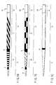
- FIGS. 1A to 1Care diagrams explaining various types of guide wires according to preferred embodiments of this invention.
- FIGS. 2A and 2Bare diagrams showing how a guide wire according to an embodiment of the invention is used.
- FIGS. 3A and 3Bare diagrams showing how a conventional guide wire is used.
- a guide wire 10comprises a core wire made of a single wire of nickel-titanium alloy, which is coated with urethane resin.
- the guide wire 10has a distal part 12 and a proximal part 13 .
- the distal part 12is flexible.
- the proximal part 13is greatly rigid.
- the distal part 12attains flexibility, because it is tapered by means of, for example, center-less polishing.
- the center-less polishingis performed over an appropriate distance, about 150 mm from the distal end in the present embodiment.
- the guide wire 10has markings 14 , 15 , 16 and 17 .
- the marking 14is a broad ring provided at a distance of, for example, 70 mm from the distal end.
- the marking 15consists of ring-shaped markers arranged at regular intervals of 3 mm, each having a width of, for example, 2 mm.
- the marking 16is a broad ring provided at a distance of, for example, 150 mm from the distal end.
- the marking 17is a spiral marker having a width of, for example, 2 mm.
- the proximal part 18starting 15 at 250 mm from the distal end, has no marking.
- the broad-ring marking 14indicates a particular depth to which or beyond which the distal part 12 should be inserted into, for example, the papilla, lest it should slip from the papilla.
- the position of the marking 14is not limited to the one shown in FIG. 1A .
- the marking 14can be provided at any other position, if it indicates the particular depth.
- the position the marking 14 should takecan be determined by the characteristic in structure or rigidity of the guide wire 10 , such as the tapering angle. It is desired that the marking 14 be a ring-like shape that uninterruptedly extends around the guide wire 10 , and have such a shape and such a size as can be reliably seen, in whichever manner it is bent.
- the mark 15which consists of ring-shaped markers arranged at intervals, makes it easy to determine whether the guide wire 10 is moving in the axial direction.
- the marking 17which is a spiral marker, makes it easy to determine whether the guide wire 10 is rotating.
- the markings 15 and 17may be of any shapes other than those shown, provided they enable the user to determine in which direction the guide wire 10 is moving or rotating.
- the markings 15 and 17may have the same shape or pattern. If they have different patterns as in this embodiment, they can help identify the distal part 12 and the proximal part 13 , respectively. Consisting of ring-shaped markers arranged at intervals, the marking 15 helps the user to determine accurately how much the guide wire 10 has moved in its axial direction.
- the marking 16i.e., the broad ring provided between the markings 15 and 17 , indicates the position at which the flexible distal part 12 terminates and the rigid proximal part 13 starts. Thus, the marking 16 will be located at a different position if the distal part 12 , which is tapered, is lengthened or shortened.
- the guide wire 10may be inserted, as the conventional guide wire, from the papilla into the pancreatic obiliary duct, through an endoscope 102 inserted in, for example, the duodenum.
- the surgeon or operatorinserts the guide wire 10 into the papilla, while observing the most distal marking 14 through the endoscope 102 . Since the marking 14 is shaped like a broad ring, it can easily be recognized whichever position the distal part 12 takes, or no matter whether the distal part 12 is inclined or rotated.
- the marking 14has been inserted into the papilla, it can no longer be seen through the endoscope 102 . This indicates that the guide wire 10 has been inserted into the papilla to a sufficient depth. If the operator manipulates the guide wire 10 , the distal part 12 will not slip out of the papilla. If the marking 14 is seen in the view field of the endoscope 102 , it indicates that the distal part 12 has not been sufficiently inserted into the papilla or has been pulled too much from the papilla. Thus, the operator can know that the distal part 12 may slip from the papilla if he or she manipulates the guide wire 10 in this condition.
- the marking 15consists of ring-shaped markers arranged at intervals and the marking 17 is a spiral marker.
- the marking 15enables the operator to determine how the guide wire 10 is moving in its axial direction
- the marking 17enables the operator to determine how the guide wire 10 is rotating. If the operator knows the width of the ring-shaped markers, he or she can easily determine how long the wire 10 has moved.
- FIG. 2Aillustrates how a catheter 104 is replaced by another, by using the guide wire 10 .
- an endoscope 102inserted into, for example, the duodenum 101 as shown in FIG. 2A .
- the catheter 104is pulled into the endoscope 102 , leaving the guide wire 10 in the duodenum 101 in the same way as the conventional guide wire.
- the catheter 104can no longer be seen in the view field of the endoscope 102 . Only the guide wire 10 is seen in the view field.
- the operatorraises the hebel 103 to the uppermost position. While the marking 16 remains in the view field of the endoscope 102 , not only the flexible distal part 12 , but also the rigid proximal part 13 projects from the endoscope 102 to a position near the hebel 103 . Hence, the rigid proximal part 13 is bent when the hebel 103 is raised. Therefore, the proximal part 13 is reliably secured to the endoscope 102 .
- the guide wire 10Since the guide wire 10 has its proximal part 13 bent and is therefore is firmly secured to the endoscope 102 , only the catheter 104 can be pulled from the endoscope 102 . After pulling the catheter 104 , another catheter (not shown) can be inserted into the endoscope 102 .
- the marking 16is inserted in the papilla when the catheter 104 is inserted into the papilla, that part of the guide wire 10 which is exposed, extending from the forceps port of the endoscope 102 to the entrance of the papilla, has sufficient rigidity.
- the catheter 104As the catheter 104 is further moved forward in this condition, it advances along the guide wire 10 and can be easily inserted into the capilla. This is because that part of the guide wire 10 which lies near the capilla is far more rigid than the catheter 104 .
- the rigidity of any part of the guide wire 10can therefore be determined through the endoscope. Further, it can be determined whether the part of the wire 10 is moving forward or backward and whether it is rotating or not. This helps the operator to manipulate the guide wire 10 easily and reliably. The guide wire 10 is greatly improved in operability.
- a guide wire 10 Aaccording to this embodiment comprises a single wire made of nickel-titanium alloy, having a tapered distal end and coated with urethane resin. A part of the distal end has a lubricant coating 19 .
- the present embodimenthas marking 14 and marking 16 .
- the marking 14is provided on the proximal end of the lubricant coating 19 .
- the marking 16is provided on the junction between the flexible distal part 12 and the rigid proximal part 13 .
- Marking 25consisting of polka dots is provided on that part of the distal part 12 , which extends between the marking 14 and the making 16 .
- Marking 27is provided on the proximal part 13 , adjacent to the marking 16 .
- the marking 14serves to prevent the guide wire 10 A from slipping out of the papilla as in the first embodiment, due to an error made in manipulating the guide wire 10 A. Unlike the marking 14 on provided on the first embodiment, which helps to determine the depth to which the wire has been inserted, the marking 14 helps to determine whether the lubricant coating 19 on the distal end of the guide wire 10 A is completely inserted in the papilla.
- the operatorcan determine whether the lubricant coating 19 has been completely inserted into the papilla or not. Hence, he or she can prevent the guide wire 10 A from slipping out of the papilla against his or her intension, while he or she is manipulating the guide wire 10 A.
- the marking 25located between the marking 14 and the marking 16 , consists of many small makers, i.e., polka dots. Therefore, the marking 25 enables the operator to determine not only how the guide wire 10 A is moving forward or backward, but also how it is rotating. Since the polka dots are arranged at specific intervals in the axial direction of the wire, the marking 25 can be used to determine how long the guide wire 10 A has moved, as in the first embodiment.
- any marking on a guide wire of this typeshould have bright color so that it may be well seen through the endoscope. If the marking is of bright color, however, it excessively reflects the intense light coming from the light source provided in the endoscope. Inevitably, the object of interest appears white in the view field of the endoscope and can hardly be recognized. (Hereinafter, this phenomenon will be referred to as “halation.”) Hence, it is desired that the guide wire 10 A has dark color and a small amount of markings of bright color are applied to the guide wire.
- the markersi.e., polka dots
- the markersare small and of bright color. This much serves to prevent halation.
- the marking 27 provided on the proximal part 13is a checkered pattern. Like the marking 25 , this marking 27 can be used to determine how the guide wire 10 A is moving forward or backward, how it is rotating, and how long the guide wire 10 A has moved.
- the guide wire 10 A according to this embodimentcan be used in the same manner as the first embodiment.
- the guide wire 10 Ahas lubricant coating 19 .
- the marking 14which is provided at the boundary between the distal part having the lubricant coating 19 and the proximal part having no lubricant coating, where the surface condition changes, may be used in place of, or together with, the markings 14 and 16 of the first embodiment, whose shapes indicate a position where the structural feature changes. Then, the marking 14 can serve to determine the lubricity.
- the lubricity and rigidity of the guide wire 10 Acan be determined from the marking 14 , marking 16 , marking 25 and marking 27 all observed through the endoscope. This improves the operability of the guide wire 10 A.
- a guide wire 10 B according to this embodimenthas marking 16 identical to the marking 16 provided on the first embodiment.
- the wire 10 Bhas no marking similar to the other markings provided on the first embodiment. Instead, it has small numerals used as markers, which are arranged in a helical line.
- the numeralsshould represent distances from the distal end. Nonetheless, they may represent other values. They may be spaced at regular intervals or any other type of intervals.
- the markersare not limited to numerals. They may be markers of any other type, e.g., characters or symbols, which can be recognized through the endoscope.
- the guide wire 10 Bachieves the same advantage as the two embodiments described above.
- the marking 14 and marking 16 on the guide wire 10 A according to the second embodimenthave been provided by the manufacturer.
- the operatormust manipulate the guide wire 10 A in accordance with the marking 14 and the marking 16 .
- the small numerals on the guide wire 10 B according to this embodimentmay assume whatever significance the operator selects in accordance with his or her taste or the patient's condition. In accordance with the numerals, the operator can manipulate the wire 10 B.
- the operatorwants to secure a soft part of the guide wire 10 B at the hebel 103 , he or she secures a flexible part of the guide wire 10 B, which is more distal than the marking 16 .
- the operatormay manipulate the guide wire, using any small numeral, for example “9” as reference mark, instead of the marking 16 .
- the markings 14 , 15 , 16 and 17 on the guide wire 10 (first embodiment) and the markings 25 and 27 on the guide wired 10 A (second embodiment), which indicate specific positions, and the marking on the guide wire 10 B (third embodiment), which consists of numerals, characters or symbols,should be provided at positions in a range between 60 mm and 400 mm from the distal end of the guide wire. This is because the guide wire would not be inserted to a depth beyond 400 mm from the papilla and because no advantages result if its structural features, such as flexibility, are sharply changed at a distance within 60 mm from the distal end. If its structural features are so changed, its behavior is unstable and may not be easily inserted. Thus, the marking should better be provided in said range.
- the position where the structural features changeis not limited to one that is based on shape.
- the positioncan be one at which the surface condition changes. For example, it is the boundary between the distal part having lubricant coating and the proximal part that having no lubricant coating.
- each guide wire according to this inventioncan be determined through an endoscope. This can prevent the guide wire from slipping from the capilla while the guide wire is being manipulated and can ultimately improve the operability of the guide wire.
Landscapes
- Health & Medical Sciences (AREA)
- Life Sciences & Earth Sciences (AREA)
- Biophysics (AREA)
- Pulmonology (AREA)
- Engineering & Computer Science (AREA)
- Anesthesiology (AREA)
- Biomedical Technology (AREA)
- Heart & Thoracic Surgery (AREA)
- Hematology (AREA)
- Animal Behavior & Ethology (AREA)
- General Health & Medical Sciences (AREA)
- Public Health (AREA)
- Veterinary Medicine (AREA)
- Media Introduction/Drainage Providing Device (AREA)
- Endoscopes (AREA)
Abstract
Description
Claims (11)
Applications Claiming Priority (1)
| Application Number | Priority Date | Filing Date | Title |
|---|---|---|---|
| PCT/JP2003/003642WO2004084712A1 (en) | 2003-03-25 | 2003-03-25 | Guide wire |
Related Parent Applications (1)
| Application Number | Title | Priority Date | Filing Date |
|---|---|---|---|
| PCT/JP2003/003642ContinuationWO2004084712A1 (en) | 2003-03-25 | 2003-03-25 | Guide wire |
Publications (2)
| Publication Number | Publication Date |
|---|---|
| US20060015040A1 US20060015040A1 (en) | 2006-01-19 |
| US8303519B2true US8303519B2 (en) | 2012-11-06 |
Family
ID=33045134
Family Applications (1)
| Application Number | Title | Priority Date | Filing Date |
|---|---|---|---|
| US11/230,038Expired - Fee RelatedUS8303519B2 (en) | 2003-03-25 | 2005-09-19 | Guide wire having markings to indicate changes in structural features |
Country Status (4)
| Country | Link |
|---|---|
| US (1) | US8303519B2 (en) |
| EP (1) | EP1607035A4 (en) |
| AU (1) | AU2003227198A1 (en) |
| WO (1) | WO2004084712A1 (en) |
Cited By (2)
| Publication number | Priority date | Publication date | Assignee | Title |
|---|---|---|---|---|
| USD847335S1 (en)* | 2015-11-26 | 2019-04-30 | Asahi Intecc Co., Ltd. | Guidewire |
| US12440374B2 (en) | 2023-01-12 | 2025-10-14 | Innovative Drive Corporation | Mechanical hole punch for the reduction of intraocular pressure and methods of use |
Families Citing this family (15)
| Publication number | Priority date | Publication date | Assignee | Title |
|---|---|---|---|---|
| WO2008013441A1 (en)* | 2006-07-26 | 2008-01-31 | Johan Willem Pieter Marsman | Facilitation of antegrade insertion of a guidewire into the superficial femoral artery |
| US8002714B2 (en) | 2006-08-17 | 2011-08-23 | Ethicon Endo-Surgery, Inc. | Guidewire structure including a medical guidewire and method for using a medical instrument |
| US9028427B2 (en) | 2007-03-14 | 2015-05-12 | Terumo Kabushiki Kaisha | Guide wire |
| JP5137544B2 (en)* | 2007-12-03 | 2013-02-06 | Hoya株式会社 | Endoscopic high-frequency treatment instrument |
| CN101918070B (en)* | 2008-01-18 | 2013-09-04 | 泰尔茂株式会社 | Guide wire |
| WO2009112048A1 (en)* | 2008-03-11 | 2009-09-17 | Epflex Feinwerktechnik Gmbh | Guide wire having marking pattern |
| CN102469927A (en)* | 2009-10-09 | 2012-05-23 | 奥林巴斯医疗株式会社 | Endoscope device |
| JP5204921B1 (en)* | 2012-12-06 | 2013-06-05 | 多摩メディカル有限会社 | Medical guide pin with scale |
| US20140277091A1 (en)* | 2013-03-14 | 2014-09-18 | Cook Medical Technologies Llc | Detachable delivery device |
| JP2015065979A (en)* | 2013-09-26 | 2015-04-13 | テルモ株式会社 | Guide wire |
| US11135350B2 (en)* | 2015-01-27 | 2021-10-05 | Stacey JACOVINI | Catheter anchor drain |
| WO2017183151A1 (en)* | 2016-04-21 | 2017-10-26 | オリンパス株式会社 | Endoscopic treatment tool |
| WO2018068125A1 (en)* | 2016-10-14 | 2018-04-19 | Patrick Gooi | Reusable ab-interno trabeculotomy system |
| US11364077B2 (en)* | 2017-03-24 | 2022-06-21 | The Spectranetics Corporation | Laser energy delivery devices including distal tip orientation indicators |
| WO2019155828A1 (en)* | 2018-02-09 | 2019-08-15 | グンゼ株式会社 | Medical guide wire |
Citations (20)
| Publication number | Priority date | Publication date | Assignee | Title |
|---|---|---|---|---|
| US4676249A (en) | 1986-05-19 | 1987-06-30 | Cordis Corporation | Multi-mode guidewire |
| US4682607A (en)* | 1985-12-02 | 1987-07-28 | Vlv Associates | Wire guide |
| US5084022A (en) | 1989-10-04 | 1992-01-28 | Lake Region Manufacturing Company, Inc. | Graduated guidewire |
| JPH04108556A (en) | 1990-08-27 | 1992-04-09 | Trinity Ind Corp | Coating booth |
| US5253653A (en) | 1991-10-31 | 1993-10-19 | Boston Scientific Corp. | Fluoroscopically viewable guidewire for catheters |
| US5320602A (en)* | 1993-05-14 | 1994-06-14 | Wilson-Cook Medical, Inc. | Peel-away endoscopic retrograde cholangio pancreatography catheter and a method for using the same |
| US5379779A (en) | 1993-08-16 | 1995-01-10 | Boston Scientific Corporation | Zebra exchange guidewire |
| US5479938A (en) | 1994-02-07 | 1996-01-02 | Cordis Corporation | Lumen diameter reference guidewire |
| US5498250A (en)* | 1994-05-18 | 1996-03-12 | Scimed Life Systems, Inc. | Catheter guide wire with multiple radiopacity |
| US5599300A (en) | 1992-05-11 | 1997-02-04 | Arrow Precision Products, Inc. | Method for electrosurgically obtaining access to the biliary tree with an adjustably positionable needle-knife |
| JPH0994298A (en) | 1995-09-28 | 1997-04-08 | Terumo Corp | Guide wire |
| US5836893A (en)* | 1996-03-08 | 1998-11-17 | Scimed Life Systems, Inc. | Intravascular guidewire |
| JPH1189940A (en) | 1997-09-24 | 1999-04-06 | Nippon Sherwood Medical Industries Ltd | Guide wire |
| JPH11137693A (en) | 1997-11-13 | 1999-05-25 | Unitika Ltd | Guide wire for medical treatment |
| US5916178A (en) | 1995-03-30 | 1999-06-29 | Medtronic, Inc. | Steerable high support guidewire with thin wall nitinol tube |
| US6036682A (en)* | 1997-12-02 | 2000-03-14 | Scimed Life Systems, Inc. | Catheter having a plurality of integral radiopaque bands |
| JP2001046508A (en) | 1999-06-01 | 2001-02-20 | Piolax Inc | Clinical guide wire |
| US6613002B1 (en)* | 1999-06-05 | 2003-09-02 | Wilson-Cook Medical Incorporated | System of indicia for a medical device |
| US7278973B2 (en)* | 2002-03-25 | 2007-10-09 | Terumo Kabushiki Kaisha | Guide wire |
| JP4108556B2 (en) | 2003-07-10 | 2008-06-25 | 株式会社エース電研 | Game ball supply device |
- 2003
- 2003-03-25WOPCT/JP2003/003642patent/WO2004084712A1/enactiveApplication Filing
- 2003-03-25AUAU2003227198Apatent/AU2003227198A1/ennot_activeAbandoned
- 2003-03-25EPEP03715400Apatent/EP1607035A4/ennot_activeCeased
- 2005
- 2005-09-19USUS11/230,038patent/US8303519B2/ennot_activeExpired - Fee Related
Patent Citations (20)
| Publication number | Priority date | Publication date | Assignee | Title |
|---|---|---|---|---|
| US4682607A (en)* | 1985-12-02 | 1987-07-28 | Vlv Associates | Wire guide |
| US4676249A (en) | 1986-05-19 | 1987-06-30 | Cordis Corporation | Multi-mode guidewire |
| US5084022A (en) | 1989-10-04 | 1992-01-28 | Lake Region Manufacturing Company, Inc. | Graduated guidewire |
| JPH04108556A (en) | 1990-08-27 | 1992-04-09 | Trinity Ind Corp | Coating booth |
| US5253653A (en) | 1991-10-31 | 1993-10-19 | Boston Scientific Corp. | Fluoroscopically viewable guidewire for catheters |
| US5599300A (en) | 1992-05-11 | 1997-02-04 | Arrow Precision Products, Inc. | Method for electrosurgically obtaining access to the biliary tree with an adjustably positionable needle-knife |
| US5320602A (en)* | 1993-05-14 | 1994-06-14 | Wilson-Cook Medical, Inc. | Peel-away endoscopic retrograde cholangio pancreatography catheter and a method for using the same |
| US5379779A (en) | 1993-08-16 | 1995-01-10 | Boston Scientific Corporation | Zebra exchange guidewire |
| US5479938A (en) | 1994-02-07 | 1996-01-02 | Cordis Corporation | Lumen diameter reference guidewire |
| US5498250A (en)* | 1994-05-18 | 1996-03-12 | Scimed Life Systems, Inc. | Catheter guide wire with multiple radiopacity |
| US5916178A (en) | 1995-03-30 | 1999-06-29 | Medtronic, Inc. | Steerable high support guidewire with thin wall nitinol tube |
| JPH0994298A (en) | 1995-09-28 | 1997-04-08 | Terumo Corp | Guide wire |
| US5836893A (en)* | 1996-03-08 | 1998-11-17 | Scimed Life Systems, Inc. | Intravascular guidewire |
| JPH1189940A (en) | 1997-09-24 | 1999-04-06 | Nippon Sherwood Medical Industries Ltd | Guide wire |
| JPH11137693A (en) | 1997-11-13 | 1999-05-25 | Unitika Ltd | Guide wire for medical treatment |
| US6036682A (en)* | 1997-12-02 | 2000-03-14 | Scimed Life Systems, Inc. | Catheter having a plurality of integral radiopaque bands |
| JP2001046508A (en) | 1999-06-01 | 2001-02-20 | Piolax Inc | Clinical guide wire |
| US6613002B1 (en)* | 1999-06-05 | 2003-09-02 | Wilson-Cook Medical Incorporated | System of indicia for a medical device |
| US7278973B2 (en)* | 2002-03-25 | 2007-10-09 | Terumo Kabushiki Kaisha | Guide wire |
| JP4108556B2 (en) | 2003-07-10 | 2008-06-25 | 株式会社エース電研 | Game ball supply device |
Cited By (2)
| Publication number | Priority date | Publication date | Assignee | Title |
|---|---|---|---|---|
| USD847335S1 (en)* | 2015-11-26 | 2019-04-30 | Asahi Intecc Co., Ltd. | Guidewire |
| US12440374B2 (en) | 2023-01-12 | 2025-10-14 | Innovative Drive Corporation | Mechanical hole punch for the reduction of intraocular pressure and methods of use |
Also Published As
| Publication number | Publication date |
|---|---|
| AU2003227198A1 (en) | 2004-10-18 |
| EP1607035A4 (en) | 2009-03-11 |
| WO2004084712A1 (en) | 2004-10-07 |
| US20060015040A1 (en) | 2006-01-19 |
| EP1607035A1 (en) | 2005-12-21 |
Similar Documents
| Publication | Publication Date | Title |
|---|---|---|
| US8303519B2 (en) | Guide wire having markings to indicate changes in structural features | |
| US7758565B2 (en) | Identifiable wire guide | |
| EP1854500A1 (en) | Treatment tool inserting/withdrawing auxiliary device | |
| US5749887A (en) | Twisted strand localization wire | |
| US6613002B1 (en) | System of indicia for a medical device | |
| US9089258B2 (en) | Endoscopic methods and devices for transnasal procedures | |
| JP5512716B2 (en) | Guide wire | |
| US20210113092A1 (en) | Introduction of shaped medical instruments into the body of a subject | |
| EP1299033B1 (en) | System of indicia for a medical device | |
| WO2012002299A1 (en) | Catheter | |
| JP2012071145A (en) | End effector for surgical instrument, surgical instrument, and method for forming the end effector | |
| AU2001229024A1 (en) | System of indicia for a medical device | |
| JP2006150066A (en) | Medical guide wire | |
| WO2010082399A1 (en) | Selective cannulation method to lumen tissue having branch site and endoscopic tool | |
| CA2622519A1 (en) | Multiple stage wire guide | |
| JP2024533097A (en) | Microcatheter Caliper | |
| JP4970677B2 (en) | Guide wire | |
| JP5032760B2 (en) | Medical guidewire | |
| CN108495683A (en) | Anchor seal wire | |
| US20080097190A1 (en) | Slitted marker | |
| JP2008132027A (en) | Delivery device for tubular organ treatment instrument | |
| CN113597323B (en) | Guide wire | |
| JP3179894U (en) | catheter | |
| JPH10118011A (en) | Endoscope system using stylet | |
| JP4402814B2 (en) | Medical guidewire |
Legal Events
| Date | Code | Title | Description |
|---|---|---|---|
| AS | Assignment | Owner name:OLYMPUS CORPORATION, JAPAN Free format text:ASSIGNMENT OF ASSIGNORS INTEREST;ASSIGNORS:YUNOKI, SEIKO;SHIBAKI, KENJI;IWASAKA, MASAYUKI;SIGNING DATES FROM 20050825 TO 20050905;REEL/FRAME:017016/0025 Owner name:OLYMPUS CORPORATION, JAPAN Free format text:ASSIGNMENT OF ASSIGNORS INTEREST;ASSIGNORS:YUNOKI, SEIKO;SHIBAKI, KENJI;IWASAKA, MASAYUKI;REEL/FRAME:017016/0025;SIGNING DATES FROM 20050825 TO 20050905 | |
| ZAAA | Notice of allowance and fees due | Free format text:ORIGINAL CODE: NOA | |
| ZAAB | Notice of allowance mailed | Free format text:ORIGINAL CODE: MN/=. | |
| STCF | Information on status: patent grant | Free format text:PATENTED CASE | |
| FEPP | Fee payment procedure | Free format text:PAYOR NUMBER ASSIGNED (ORIGINAL EVENT CODE: ASPN); ENTITY STATUS OF PATENT OWNER: LARGE ENTITY | |
| FPAY | Fee payment | Year of fee payment:4 | |
| AS | Assignment | Owner name:OLYMPUS CORPORATION, JAPAN Free format text:CHANGE OF ADDRESS;ASSIGNOR:OLYMPUS CORPORATION;REEL/FRAME:039344/0502 Effective date:20160401 | |
| MAFP | Maintenance fee payment | Free format text:PAYMENT OF MAINTENANCE FEE, 8TH YEAR, LARGE ENTITY (ORIGINAL EVENT CODE: M1552); ENTITY STATUS OF PATENT OWNER: LARGE ENTITY Year of fee payment:8 | |
| FEPP | Fee payment procedure | Free format text:MAINTENANCE FEE REMINDER MAILED (ORIGINAL EVENT CODE: REM.); ENTITY STATUS OF PATENT OWNER: LARGE ENTITY | |
| LAPS | Lapse for failure to pay maintenance fees | Free format text:PATENT EXPIRED FOR FAILURE TO PAY MAINTENANCE FEES (ORIGINAL EVENT CODE: EXP.); ENTITY STATUS OF PATENT OWNER: LARGE ENTITY | |
| STCH | Information on status: patent discontinuation | Free format text:PATENT EXPIRED DUE TO NONPAYMENT OF MAINTENANCE FEES UNDER 37 CFR 1.362 | |
| FP | Lapsed due to failure to pay maintenance fee | Effective date:20241106 |