US8301762B1 - Service grouping for network reporting - Google Patents
Service grouping for network reportingDownload PDFInfo
- Publication number
- US8301762B1 US8301762B1US12/480,681US48068109AUS8301762B1US 8301762 B1US8301762 B1US 8301762B1US 48068109 AUS48068109 AUS 48068109AUS 8301762 B1US8301762 B1US 8301762B1
- Authority
- US
- United States
- Prior art keywords
- customer
- port
- ports
- data
- physical
- Prior art date
- Legal status (The legal status is an assumption and is not a legal conclusion. Google has not performed a legal analysis and makes no representation as to the accuracy of the status listed.)
- Expired - Fee Related, expires
Links
Images


Classifications
- H—ELECTRICITY
- H04—ELECTRIC COMMUNICATION TECHNIQUE
- H04L—TRANSMISSION OF DIGITAL INFORMATION, e.g. TELEGRAPHIC COMMUNICATION
- H04L41/00—Arrangements for maintenance, administration or management of data switching networks, e.g. of packet switching networks
- H04L41/08—Configuration management of networks or network elements
- H04L41/085—Retrieval of network configuration; Tracking network configuration history
- H04L41/0853—Retrieval of network configuration; Tracking network configuration history by actively collecting configuration information or by backing up configuration information
- G—PHYSICS
- G06—COMPUTING OR CALCULATING; COUNTING
- G06F—ELECTRIC DIGITAL DATA PROCESSING
- G06F16/00—Information retrieval; Database structures therefor; File system structures therefor
- G06F16/20—Information retrieval; Database structures therefor; File system structures therefor of structured data, e.g. relational data
- G06F16/28—Databases characterised by their database models, e.g. relational or object models
- G06F16/284—Relational databases
- G06F16/285—Clustering or classification
- H—ELECTRICITY
- H04—ELECTRIC COMMUNICATION TECHNIQUE
- H04L—TRANSMISSION OF DIGITAL INFORMATION, e.g. TELEGRAPHIC COMMUNICATION
- H04L41/00—Arrangements for maintenance, administration or management of data switching networks, e.g. of packet switching networks
- H04L41/12—Discovery or management of network topologies
- H—ELECTRICITY
- H04—ELECTRIC COMMUNICATION TECHNIQUE
- H04L—TRANSMISSION OF DIGITAL INFORMATION, e.g. TELEGRAPHIC COMMUNICATION
- H04L41/00—Arrangements for maintenance, administration or management of data switching networks, e.g. of packet switching networks
- H04L41/22—Arrangements for maintenance, administration or management of data switching networks, e.g. of packet switching networks comprising specially adapted graphical user interfaces [GUI]
- H—ELECTRICITY
- H04—ELECTRIC COMMUNICATION TECHNIQUE
- H04L—TRANSMISSION OF DIGITAL INFORMATION, e.g. TELEGRAPHIC COMMUNICATION
- H04L43/00—Arrangements for monitoring or testing data switching networks
- H04L43/08—Monitoring or testing based on specific metrics, e.g. QoS, energy consumption or environmental parameters
- H04L43/0805—Monitoring or testing based on specific metrics, e.g. QoS, energy consumption or environmental parameters by checking availability
- H04L43/0817—Monitoring or testing based on specific metrics, e.g. QoS, energy consumption or environmental parameters by checking availability by checking functioning
Definitions
- a network service providermay monitor the status of network devices through a network monitoring system that includes network data for network devices.
- a customermay use computers at a specific location for a specific purpose, such as communicating with the customer's other sales centers and distribution centers.
- the network monitoring systemmay not have customer data that would readily enable a technician or a customer to monitor the operation of network devices that provide service to the customer or to evaluate the effect of the network devices on communication with the customer's other sales centers and distribution centers.
- a systemfor service grouping in network reporting.
- the systemincludes a data retriever, a data analysis tool, and a user interface, each stored in a memory, and a processor.
- the data retrieverretrieves router configuration data from data stores for routers in a service provider network.
- the data analysis toolparses the router configuration data to create port data for each port on each router in the service provider network and integrates the port data with customer data to create an integrated database.
- the data analysis toolalso identifies ports associated with a customer, identifies the ports associated with the customer which are bundled into bundled logical ports, and identifies the ports associated with the customer which are partitioned into partitioned logical ports.
- the data analysis toolcreates a hierarchy of port information based on the ports associated with the customer, the bundled logical ports, the partitioned logical ports, and a service provided to the customer.
- the user interfacedisplays the hierarchy of port information to enable the customer to troubleshoot ports.
- a computer implemented methodfor service grouping in network reporting.
- a data analysis tool stored in a memory and executed by a processorparses router configuration data to create port data for each port on each router in a service provider network.
- the data analysis toolintegrates the port data with customer data to create an integrated database.
- the data analysis toolidentifies ports associated with a customer.
- the data analysis toolidentifies ports associated with the customer which are bundled into bundled logical ports.
- the data analysis toolidentifies ports associated with the customer which are partitioned into partitioned logical ports.
- the data analysis toolcreates a hierarchy of port information based on the ports associated with the customer, the bundled logical ports, the partitioned logical ports, and a service provided to the customer.
- the hierarchy of port informationis displayed via a user interface stored in a memory and executed by a processor to enable the customer to troubleshoot ports.
- a systemfor service grouping in network reporting.
- the systemincludes a data retriever, a data analysis tool, and a user interface, each stored in a memory, and a processor.
- the data retrieverretrieves router configuration data from data stores for routers in a service provider network.
- the data analysis toolparses the router configuration data to create port data for each port on each router in the service provider network and integrates the port data with customer data to create an integrated database.
- the data analysis toolalso identifies ports associated with a customer, identifies the ports associated with the customer which are bundled into bundled logical ports, and identifies the ports associated with the customer which are partitioned into partitioned logical ports.
- the data analysis toolcreates a hierarchy of port information based on the ports associated with the customer, the bundled logical ports, the partitioned logical ports, a service provided to the customer, and a geographical location associated with the service.
- the user interfacedisplays the hierarchy of port information to enable the customer to troubleshoot ports.
- FIG. 1is a block diagram of an illustrative system for service grouping in network reporting according to some embodiments of the present disclosure.
- FIG. 2shows a schema for an integrated database for service grouping in network reporting according to some embodiments of the present disclosure.
- FIG. 3shows a frame of a graphical user interface for service grouping in network reporting according to some embodiments of the present disclosure.
- FIG. 4shows a method for service grouping in network reporting according to some embodiments of the present disclosure.
- FIG. 5illustrates an exemplary computer system suitable for implementing the several embodiments of the disclosure.
- a monitoring system providing service grouping in network reportingis provided to enable a customer to monitor the service provider network based on service groupings of customer links.
- a portis the physical interface between a router and a circuit or cable.
- a customer linkis the collection of all the circuits and ports that are between two end points that enable communication between those end points. For many instances, a customer link comprises a single circuit and a single port. However, some network services may bundle two or more smaller circuits to create a larger virtual circuit. These bundles may be associated with two or more ports. All of the ports providing a bundled service may be located on the same router card. The monitoring system determines which ports provide a bundled service and treats those ports accordingly. The monitoring system also allocates every port into customer links.
- the monitoring systemretrieves router configuration data to create an integrated database.
- the monitoring systemaccesses network information in router configuration data stores instead of directly accessing routers, thus eliminating the possibility of interfering with router operation.
- the systemintegrates the network information with customer information to create an integrated database for subsequent access.
- a data analysis toolidentifies ports associated with a customer, identifies the ports associated with the customer which are bundled into bundled logical ports, and identifies the ports associated with the customer which are partitioned into partitioned logical ports. For example, the data analysis tool may identify that a customer purchased services supported by three physical ports. Each of the first two physical ports provides the capability for a data service to communicate at 1.5 megabits per second, and may be bundled as a first service grouping into a bundled logical port that provides the capability for a high-speed data service to communicate at 3.0 megabits per second.
- the third physical portmay be partitioned as a second service grouping into two partitioned logical ports, with one of the partitioned logical ports enabling internal network communication and the other partitioned logical port enabling external Internet access.
- the data analysis toolcreates a hierarchy of port information based on the ports associated with the customer, the bundled logical ports, the partitioned logical ports, and a service provided to the customer. Based on the service groupings derived from the configurations of the ports, the hierarchy of port information may depict logical ports and physical ports at a primary level of port information presented to the customer and depict logical ports and physical ports at a secondary level of port information presented to the customer.
- the hierarchy of port informationdepicts the bundled logical port of the first service grouping and the partitioned logical ports of the second service grouping as the primary level of port information presented to the customer and the unbundled physical ports of the first service grouping and the partitioned physical port of the second service grouping as a secondary level of port information presented to the customer.
- a user interfacedisplays the hierarchy of port information to enable the customer to troubleshoot ports.
- the customerpurchased a high-speed data service that may communicate at 3.0 megabits per second, an internal network connection, and an external Internet connection.
- a customermay use the user interface to view port information, but displaying the information associated with the three physical ports that provide the customer's services may cause customer confusion due to the customer's expectations of viewing a high-speed data service, an internal network connection, and an external Internet connection.
- the user interfacedisplays information associated with the logical ports and the supporting physical ports that provide the customer services in a manner that matches the customer's expectations.
- the customermay view the primary level of port information to identify a potential problem with a logical port, and select to view port information associated with any physical ports that support the logical port in question. If the customer identifies that one of the physical ports that provides the capability for a data service to communicate at 1.5 megabits per second is down, the customer can better report the problem to a customer service technician.
- the hierarchy of port informationnot only presents port information to the customer based on the customer's expectations, but also enables the customer to troubleshoot logical and physical ports whenever customer service is impacted.
- the system 100includes a network 102 , a sales center 104 , a distribution center 106 , a database server 108 , and a user interface 110 .
- the network 102enables communications for the centers 104 - 106 .
- the centers 104 - 106may be any type of centers 104 - 106 .
- the database server 108monitors communications by the centers 104 - 106 on the network 102 .
- the user interface 110enables a user to interface with the database server 108 .
- the database server 108stores data retrieved by a data retriever 112 that accesses the network 102 .
- the data retriever 112retrieves network data 114 from network devices, such as a first router 116 and a second router 118 that communicate as part of the network 102 .
- the network data 114may include data that identifies which routers, cards, and ports are connected to which customers at which locations.
- the network 102may include thousands of routers 116 - 118 for routing messages between computers. Each router 116 - 118 forwards data packets across the network 102 toward their destinations.
- the first router 116sends and receives data packets for a first external computer 120 and a first internal computer 122 at the sales center 104 ; and the second router 118 sends and receives data packets for a second external computer 124 and a second internal computer 126 at the distribution center 106 .
- the sales center 104may use the first external computer 120 to communicate with external customer computers over an external network, such as the Internet.
- the sales center 104may use the first internal computer 122 to communicate in a customer network with other internal customer computers, such as the second internal computer 126 at the distribution center 106 .
- the distribution center 106may use the second external computer 124 to communicate with external customer computers over an external network, such as the Internet.
- the distribution center 106may use the second internal computer 126 to communicate in the customer network with other internal customer computers, such as the first internal computer 122 at the sales center 104 .
- the network data 114may include data for multiple networks 102 , with each network 102 including any number of routers 116 - 118 and data for each of the routers 116 - 118 .
- the network data 114may be compiled from router configuration data that is stored off-line in a data store as a recovery file to enable a router to recover after power outages or router maintenance.
- the router configuration datamay include which customer computer is linked to which port on which card for which router.
- the router configuration data for the first router 116may be stored in a file in non-volatile memory in a first router configuration data store 128 .
- the first router configuration data store 128may be a backup data store associated with or on board the first router 116 .
- the router configuration data for the second router 118may be stored in a file in non-volatile memory in a second router configuration data store 130 .
- the data retriever 112By accessing router configuration data in the first router configuration data store 128 and the second router configuration data store 130 , the data retriever 112 has the option of not directly accessing the first router 116 or the second router 118 . Not directly accessing routers reduces the possibility of interfering with router operation.
- the on-line routers 116 - 118may store their router configuration data in the off-line backup data stores 128 - 130 periodically, such as each day when throughput is low.
- the network data 114may alternatively be in part compiled from the router configuration data that is used by the routers 116 - 118 .
- the first router 116includes a first card 132 and a second card 134
- the second router 118includes a third card 136 .
- Each card 132 - 136may include multiple ports that each link with a customer computer.
- the first card 132includes a first port 138 and a second port 140
- the second card 134includes a third port 142 and a fourth port 144
- the third card 136includes a fifth port 146 and a sixth port 148 .
- One customermay have multiple customer computers that link to the network 102 through the routers 116 - 118 .
- the sales center 104 for the customerincludes the first external computer 120 linked to both the first port 138 and the second port 140 on the first card 132 on the first router 116 , and the first internal computer 122 linked to the third port 142 on the second card 134 on the first router 116 . Additionally, the distribution center 106 for the customer includes the second external computer 124 linked to the fifth port 146 on the third card 136 on the second router 118 and the second internal computer 126 also linked to the fifth port 146 on the third card 136 on the second router 118 .
- the database server 108stores the network data 114 separate from customer data 150 , which may be entered from the user interface 110 .
- the database server 104includes a data analysis tool 152 that integrates the network data 114 with the customer data 150 to create an integrated database 154 .
- the network data 114includes the port data for the individual ports 138 - 148 .
- the data analysis tool 152may receive input from a user through the user interface 110 and display the network data 114 and the customer data 150 from the integrated database 154 on the user interface 110 .
- the data retriever 112retrieves the network data 114 from the network 102 to provide to the data analysis tool 152 to store in the integrated database 154 . Although depicted as retrieving the network data 114 from only one network, the network 102 , the data retriever 112 may retrieve the network data 114 from any number of networks 102 .
- the data analysis tool 152may integrate the network data 114 from any number of networks 102 with the customer data 150 to create the integrated database 154 .
- the data analysis tool 152identifies the ports associated with a customer, identifies the ports associated with the customer which are bundled into bundled logical ports, and identifies the ports associated with the customer which are partitioned into partitioned logical ports. For example, the data analysis tool 152 may identify that a customer purchased services supported by four physical ports 138 , 140 , 142 , and 146 .
- the servicesmay be a voice communication service, a data communication service, a frame relay service, and/or an asynchronous transfer mode service.
- each of the physical ports 138 and 140 that provide the capability for a data service to communicate at 1.5 megabits per secondmay be bundled into a bundled logical port that provides the capability for a high-speed data service to communicate at 3.0 megabits per second for a data service.
- the data analysis tool 152may combine information associated with the ports which are bundled into the bundled logical ports to create information associated with the bundled logical ports. For example, the data analysis tool 152 combines information associated with the ports 138 and 140 to create information associated with the bundled logical port for the first external computer 120 .
- the physical port 146may be partitioned into two partitioned logical ports, with one of the partitioned logical ports enabling internal network communication for the second internal computer 126 and the other partitioned logical port enabling external Internet access for the second external computer 124 .
- the partitioned logical portsmay be separated by a firewall that enables the physical port 146 to provide two different services to the computers 124 and 126 .
- the data analysis tool 152may divide information associated with the ports which are partitioned into partitioned logical ports to create information associated with each of the partitioned logical ports. For example, the data analysis tool 152 divides information associated with the physical port 146 to create information associated with each of the partitioned logical ports for the computers 124 and 126 .
- the data analysis tool 152creates a hierarchy of port information based on the ports associated with the customer, the bundled logical ports, the partitioned logical ports, and a service provided to the customer.
- the hierarchy of port informationdepicts the bundled logical port and the partitioned logical ports as the primary level of port information presented to the customer and depicts the port 142 , the unbundled physical ports 138 and 140 , and the partitioned physical port 146 as a secondary level of port information presented to the customer.
- the hierarchy of port informationmay include a parent port that is associated with a child port.
- the data analysis tool 152may determine parent ports and child ports based on applying a set of rules to the customer's ports and the customer service groupings derived from the configurations of a customer's ports.
- the data analysis tool 152also may display port information via the user interface 110 to enable a user to determine the parent ports and the child ports based on the customer's ports and the customer services provided by the customer's ports. For example, the data analysis tool 152 creates a hierarchy of port information that depicts the bundled logical port that provides the capability to communicate at 3.0 megabits per second for a data service as a parent port at the primary level of port information presented to the customer.
- the hierarchy of port informationdepicts each of the unbundled physical ports 138 and 140 that provide the capability to communicate at 1.5 megabits per second as the child ports at a secondary level of port information presented to the customer.
- the customermay initially view the bundled logical port for the data service that communicates at 3.0 megabits per second as a parent port at the primary level of port information.
- the hierarchy of port informationmay include information associated with an internet protocol address, a product, a characteristic, a bandwidth allocation, and/or an operational detail. For example, the customer may view the primary level of port information and notice that an operational detail indicates that the bundled logical port is communicating at significantly less than 3.0 megabits per second even though the bandwidth allocation for this port is for 3.0 megabits per second.
- the customermay select for the bundled logical port to display the child ports of this parent port. If the customer views the secondary level of port information that displays the child ports of the selected parent port, the customer may notice that the unbundled physical port 138 is communicating at significantly less than 1.5 megabits per second, which may be the cause for the bundled logical port communicating at significantly less than 3.0 megabits per second.
- the hierarchy of port informationmay include a history of information associated with the operational detail.
- the operational detail for the unbundled physical port 138may indicate that the port 138 was communicating at 1.5 megabits per second during a first time period, communicating at 1.0 megabits per second during a second time period, and communicating at 0.5 megabits per second during a third time period. Viewing the history of this operational detail may enable a customer to detect trends or patterns in their customer service. Depicting the hierarchy of port information as relationships between parent ports and child ports in the hierarchy of port information may enable a customer to examine a high level overview of customer services and detect problems with ports before the problems become more serious.
- the hierarchy of port informationmay include a first peer port that relates to a second peer port based on the service provided to the customer.
- a first peer portmay be a port associated with inbound communications for a gateway and a second peer port may be a port associated with outbound communications for the gateway.
- the hierarchy of port informationmay depict one of the peer ports as a parent port at the primary level of port information and the other peer port as a child port at the secondary level of port information.
- the customermay view one of the peer ports as a parent port at the primary level of port information, and the customer may select for the peer port to display the child port of this parent port.
- the customermay view the secondary level of port information that displays the other peer port as a child port of the selected parent port.
- the hierarchy of port informationmay depict logical ports and physical ports at the primary level of port information presented to the customer and depict logical ports and physical ports at the secondary level of port information presented to the customer.
- the user interface 110displays the hierarchy of port information to enable the customer to troubleshoot ports.
- the customerpurchased a connection that may communicate at 3.0 megabits per second and an internal network connection that may communicate at 1.5 megabits per second for the sales center 104 , and purchased both an internal network connection and an external Internet connection that each may communicate at 0.75 megabits per second for the distribution center 106 .
- the user interface 110displays information associated with the two logical ports and the four supporting physical ports that provide the customer services in a manner that matches the customer's expectations.
- the user interface 110initially may display only a portion of the ports associated with the customer, the bundled logical ports, and the partitioned logical ports.
- the user interface 110may respond to a selection to view more information by displaying a previously un-displayed port of the ports associated with the customer, the bundled logical ports, and the partitioned logical ports.
- the user interface 110initially displays the bundled logical port that provides the capability to communicate at 3.0 megabits per second for a data service as a parent port at the primary level of port information presented to the customer, but does not initially display the unbundled physical ports 138 and 140 that are the child ports for the bundled logical port that serves as their parent port.
- the user interface 110displays each of the unbundled physical ports 138 and 140 that provide the capability to communicate at 1.5 megabits per second as the child ports at a secondary level of port information presented to the customer.
- the user interface 110may either continue displaying the parent port or discontinue displaying the parent port.
- the user interface 110may display a port as duplicate ports.
- the customerpurchased an internal network connection that may communicate at 0.75 megabits per second for the second internal computer 126 at the distribution center 106 and an external Internet connection that may communicate at 0.75 megabits per second for the second external computer 124 at the distribution center 106 .
- the network service providerpartitioned the fifth port 146 that may communicate at 1.5 megabits per second into two partitioned logical ports that each may communicate at 0.75 megabits per second to provide an internal network connection and an external Internet connection at the distribution center 106 .
- the hierarchy of port informationmay depict the two partitioned logical ports that provide the internal network connection and the external Internet connection as parent ports at the primary level of port information presented to the customer.
- the user interface 110may display the fifth port 146 that may communicate at 1.5 megabits per second as the child port of the first partitioned logical port that may communicate at 0.75 megabits per second. If the customer selects to view more information associated with the second partitioned logical port that provides the external network connection, the user interface 110 may display the fifth port 146 that may communicate at 1.5 megabits per second as the child port of the second partitioned logical port that may communicate at 0.75 megabits per second.
- the user interface 110may display the fifth port 146 that may communicate at 1.5 megabits per second as the child port of both the first partitioned logical port and the second partitioned logical port that each may communicate at 0.75 megabits per second. In this situation, the user interface 110 displays the fifth port 146 twice in the same hierarchy of port information. Although data management rules tend to prohibit displaying duplicate information, the user interface 110 may display some ports as duplicate ports to enable customers to understand the relationship between the logical ports and the physical ports that provide their customer service.
- the customermay use the user interface 110 to view the primary level of port information to identify a potential problem with a logical port and select to view port information associated with any physical ports that support the logical port in question.
- the hierarchy of port informationnot only presents port information to the customer based on the customer's expectations, but also enables the customer to troubleshoot logical and physical ports whenever customer service is impacted. If the customer views the hierarchy of port information and detects a port problem, the customer may generate a trouble ticket for failed ports or request the network service provider to generate the trouble ticket.
- the schema 200includes the integrated database 154 , customer accounts 202 , router data 204 , and port data 206 .
- the integrated database 154includes the network data 114 and the customer data 150 .
- the customer data 150is related to the customer accounts 202 , which may be a customer database that includes business information, such as billing plans, billing information, and customer names lists 208 .
- Each of the customer names lists 208includes a list of one or more customer names used by a specific customer. For example, “Great Gadgets Corporation,” “Great Gadgets Corp.,” “Great Gadgets,” and “Great Corp.” may be customer names used by the customer Great Gadgets Corporation. In contrast, “Great Games Company” is a customer name used by a customer that is unrelated to Great Gadgets Corporation.
- the integrated database 154uses the customer names lists 208 to integrate the network data 114 with the corresponding customer in the customer data 150 .
- the network data 114 for “Great Gadgets Corporation,” “Great Gadgets Corp.,” “Great Gadgets,” and “Great Corp.”are integrated with the customer data 150 for the customer Great Gadgets Corporation, but the network data 114 for “Great Games” is integrated with the customer data 150 for a different customer.
- the integrated database 154may present customer names from the customer names lists 208 to a user through the user interface 110 to enable the user to select which customer names in the customer names lists 208 correspond to which customers.
- the network data 114includes router data 204 , which includes network information, such as card data 210 for a specific router.
- the network data 114may include data for multiple networks, with each network including any number of routers and data for each of the routers.
- the router data 204may be based on router configuration data that is stored off-line in a data store as a recovery file to enable a router to recover after power outages or router maintenance.
- the router data 204includes the card data 210
- the card data 210includes the port data 206 , which may include connectivity information that specifies which specific ports located on specific cards are connected to which customer locations.
- the data retriever 112retrieves the router data 204 , which the database server 108 parses to determine the card data 210 and the port data 206 related to the card data 210 . Only one instance of the port data 206 is depicted for the purpose of illustration, but each card may include multiple ports and the card data 210 may be related to instances of the port data 206 for each port.
- the port data 206includes a customer name 212 , a customer location 214 , and a customer link 216 .
- the port data 206may also include customer bandwidth, status, configuration, and data output.
- the integrated database 154uses the customer name 212 for a specific port with the customer names lists 208 to determine to which customer the specific port corresponds. By determining which specific ports correspond to which customers, the database server 108 may respond to a selection through the user interface 110 to view more information associated with a specific service group of customer ports by displaying the port data 206 for each port that corresponds to the specific customer service group.
- the customer location 214may include a geographic location for a specific router, such as New York, Chicago, or Atlanta.
- the customer location 214also may include the street address for a customer linked to a specific router.
- the integrated database 154may display the router data 204 for each router related to the customer that is at a general or specific location selected through the user interface 110 . For example, if a user requests to view port information for ports that identify Atlanta as a general location and Great Gadgets Corporation as a customer, the integrated database 154 displays the router data 204 for each of Great Gadgets Corporation's routers that are located in Atlanta.
- parsing the router data 204may determine the port data 206 that specifies the customer name 212 for a port is “Great Corp.” and the customer link is between the first external computer 120 at the sales center 104 and both the first port 138 and the second port 140 on the first card 132 on the first router 116 .
- parsing the router data 204may determine the customer location 214 that specifies Chicago as the geographic location for the router that contains the port and the customer link is between the first internal computer 122 at the sales center 104 and the third port 142 on the second card 134 on the first router 116 .
- the port data 206 related to the network data 114specifies that the customer name 212 for the first port 138 is “Great Corp.,” and the port data 206 related to the network data 114 specifies that the customer name 212 for the second port 140 is “Great Corp.”
- the database server 108integrates the port data 206 for the first port 138 and the port data 206 for the second port 140 with the customer data 150 for Great Gadgets Corporation.
- the database server 108stores this integrated network data 114 and customer data 150 in the integrated database 154 .
- the integrated database 154may include network data 114 that is both current and historical data. Because a customer may communicate through multiple networks from the same location, the integrated database 154 may display the name of the corresponding network along with the router data 204 for each router.
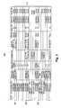
- FIG. 3shows a frame 300 of a graphical user interface for service grouping in network reporting according to some embodiments of the present disclosure.
- the numbers and types of each element in FIG. 3are depicted for the purpose of an illustrative example, as the frame 300 may include any number and type of elements. Additionally, the graphic user interface may contain other frames and control elements.
- the database server 108may provide the frame 300 via the user interface 110 to enable a user to troubleshoot ports.
- the frame 300depicts a hierarchy of port information that includes a H 302 column, a circuit identifier column 304 , a product column 306 , a speed column 308 , an IP address column 310 , a street column 312 , a city column 314 , a state column 316 , a status column 318 , a details column 320 , and rows 322 that correspond to each of the columns 302 - 320 .
- the rows 322include rows 324 of information for ports in Delaware, rows 326 of information for ports in Virginia, and rows 328 of information for ports in Texas.
- the H column 302list the hierarchy position for corresponding ports, such as a “+” for a parent port which does not have its child ports currently displayed, a “ ⁇ ” for a parent port which has its child ports currently displayed, and a “ ⁇ ” for child ports that are currently displayed.
- the circuit identifier column 304displays the identifier for the circuit for a corresponding port. When a parent port is selected to view more information, the circuit identifier column 304 may display the virtual private network routing and forwarding technology identifier and the data link connection identifier for corresponding child ports in a virtual private network.
- the product column 306displays products that provide customer service for corresponding ports.
- the product column 306may display whether a corresponding child port is a logical port or a physical port.
- the speed column 308displays allocated bandwidth for corresponding ports. When a parent port is selected to view more information, the speed column 308 may display allocated bandwidth for corresponding child ports.
- the IP address column 310displays the internet protocol address for corresponding ports. When a parent port is selected to view more information, the IP address column 310 may display the internet protocol address for corresponding child ports.
- the street column 312displays the physical street address, such as 8180 Upland Cir., associated with corresponding ports.
- the city column 314displays the city, such as Newark, associated with corresponding ports.
- the state column 316displays the state, such as Texas, associated with corresponding ports.
- the status column 318displays whether a corresponding port is operational or not.
- the details column 320displays operational details for a corresponding port, such as a current rate of communication.
- the rows 324display the hierarchy of port information for the customer's ports in the state of Delaware.
- the rows 324initially displayed information for three parent ports that were each labeled with a “+” sign.
- the “+” sign for the second parent portchanged to a “ ⁇ ” sign and the frame 300 displayed information for the four child ports for the selected parent port. If the customer selects to view less information associated with the second of the three parent ports again, the “ ⁇ ” sign for the second parent port changes to a “+” sign and the frame 300 no longer displays information for the four child ports for the selected parent port.
- the selected parent portis a bundled logical port that provides a communication speed that is equivalent to four T ⁇ 1 lines, which are also known as digital signal 1 lines.
- the four displayed child portsare physical ports that each provides a T ⁇ 1 line. If the customer notices a change in service for the bundled logical port that serves as the parent port for the four physical ports, the customer may select to view the details 320 of the parent port, select the parent port to view the four child ports, and select to view the details 320 for each of the physical ports that are the child ports of the bundled logical port.
- the rows 326display the hierarchy of port information for the customer's ports in the state of Virginia.
- the rows 326initially displayed information for one parent port that was labeled with a “+” sign.
- the “+” sign for the parent portchanged to a “ ⁇ ” sign and the frame 300 displayed information for the two child ports for the selected parent port.
- the “ ⁇ ” sign for the parent portchanges to a “+” sign and the frame 300 no longer displays information for the two child ports for the selected parent port.
- the parent portis a physical port that is partitioned into two logical partitioned ports to provide both voice and data communication for the customer's location in Virginia.
- the two displayed child portsare the logical partitioned ports for voice and data communications. If the customer notices a change in service for the physical port that serves as the parent port for the two partitioned logical ports, the customer may select to view the details 320 of the parent port, select the parent port to view the two child ports, and select to view the details 320 for each of the partitioned logical ports that are the child ports of the physical port.
- the rows 328display the hierarchy of port information for the customer's ports in the state of Texas.
- the rows 328initially displayed information for three parent ports that were each labeled with a “+” sign.
- the “+” sign for the second parent portchanged to a “ ⁇ ” sign and the frame 300 displayed information for the four child ports for the selected parent port. If the customer selects to view less information associated with the second of the three parent ports again, the “ ⁇ ” sign for the second parent port changes to a “+” sign and the frame 300 no longer displays information for the four child ports for the selected parent port.
- the selected parent portis a bundled logical port that provides a communication speed that is equivalent to two T ⁇ 1 lines.
- the four displayed child portsare two physical ports that each provides a T ⁇ 1 line and two partitioned logical ports that provide voice communication and data communication. If the customer notices a change in service for the bundled logical port that serves as the parent port for the two physical ports and the two logical ports, the customer may select to view the details 320 of the parent port, select the parent port to view the four child ports, and select to view the details 320 for each of the physical ports and logical ports that are the child ports of the bundled logical port.
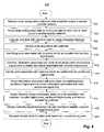
- FIG. 4a method 400 for service grouping in network reporting is depicted according to some embodiments of the present disclosure. Executing the method 400 results in creating a database of port data and customer data, identifying physical ports and logical ports associated with a customer, creating a hierarchy of port information based on the logical ports and the physical ports, and displaying the hierarchy of port information to enable a customer to troubleshoot ports.
- router configuration datais retrieved from data stores for routers in a service provider network.
- the data retriever 112retrieves the router configuration data from the router configuration data stores 128 - 130 so that the on-line routers are not directly accessed during normal operations.
- router configuration datais parsed to determine port data for each port on each router in a service provider network.
- the data retriever 112retrieves the router data 204 and the database server 108 parses the router data 204 to determine the port data 206 for each port on each router.
- the data retriever 112retrieves the router data 204 and parses the router data 204 to determine the port data 206 for each port on each router.
- port datais integrated with customer data to create an integrated database.
- the database server 108uses the customer name 212 for each port on each router in combination with the customer names lists 208 to integrate the customer data 150 with the network data 114 , which includes the port data 206 , to create the integrated database 154 .
- ports associated with a customerare identified.
- the data analysis tool 152identifies the ports 138 - 148 associated with a customer.
- ports associated with a customer which are bundled into bundled logical portsare identified.
- the data analysis tool 152identifies the ports 138 and 140 which are bundled into a bundled logical port for the first external computer 120 .
- information associated with ports which are bundled into bundled logical portsis combined to create information associated with bundled logical ports.
- the data analysis tool 152combines information associated with the ports 138 and 140 to create information associated with the bundled logical port for the first external computer 120 .
- ports which are partitioned into partitioned logical portsare identified.
- the data analysis tool 152identifies the port 146 which is partitioned into partitioned logical ports for the second external computer 124 and the second internal computer 126 .
- information associated with ports which are partitioned into partitioned logical portsis divided to create information associated with each partitioned logical port.
- the data analysis tool 152divides information associated with the port 146 to create information associated with the partitioned logical ports for the second external computer 124 and the second internal computer 126 .
- a hierarchy of port informationis created based on ports associated with a customer, bundled logical ports, partitioned logical ports, and service provided to the customer.
- the data analysis tool 152creates a hierarchy of port information based on the ports 138 - 148 , the bundled logical port for the first external computer 120 , the partitioned logical ports for the second external computer 124 and the second internal computer 126 , and the services provided to the customer.
- a hierarchy of port informationis displayed via a user interface to enable a customer to troubleshoot ports.
- the user interface 110displays the frame 300 to enable the customer to troubleshoot ports.
- a trouble ticketis optionally generated for failed ports based on troubleshooting ports.
- the user interface 110generates a trouble ticket for failed ports based on the customer detecting that the unbundled physical port 138 is currently communicating at 0.0 megabits per second with a flag that indicates that the unbundled physical port 138 is down.
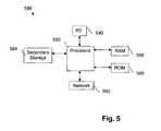
- FIG. 5illustrates a computer system 580 suitable for implementing one or more embodiments disclosed herein.
- the computer system 580includes a processor 582 (which may be referred to as a central processor unit or CPU) that is in communication with memory devices including secondary storage 584 , read only memory (ROM) 586 , random access memory (RAM) 588 , input/output (I/O) devices 590 , and network connectivity devices 592 .
- the processor 582may be implemented as one or more CPU chips.
- a design that is still subject to frequent changemay be preferred to be implemented in software, because re-spinning a hardware implementation is more expensive than re-spinning a software design.
- a design that is stable that will be produced in large volumemay be preferred to be implemented in hardware, for example in an application specific integrated circuit (ASIC), because for large production runs the hardware implementation may be less expensive than the software implementation.
- ASICapplication specific integrated circuit
- a designmay be developed and tested in a software form and later transformed, by well known design rules, to an equivalent hardware implementation in an application specific integrated circuit that hardwires the instructions of the software.
- a machine controlled by a new ASICis a particular machine or apparatus, likewise a computer that has been programmed and/or loaded with executable instructions may be viewed as a particular machine or apparatus.
- the secondary storage 584is typically comprised of one or more disk drives or tape drives and is used for non-volatile storage of data and as an over-flow data storage device if RAM 588 is not large enough to hold all working data. Secondary storage 584 may be used to store programs which are loaded into RAM 588 when such programs are selected for execution.
- the ROM 586is used to store instructions and perhaps data which are read during program execution. ROM 586 is a non-volatile memory device which typically has a small memory capacity relative to the larger memory capacity of secondary storage 584 .
- the RAM 588is used to store volatile data and perhaps to store instructions. Access to both ROM 586 and RAM 588 is typically faster than to secondary storage 584 .
- I/O devices 590may include printers, video monitors, liquid crystal displays (LCDs), touch screen displays, keyboards, keypads, switches, dials, mice, track balls, voice recognizers, card readers, paper tape readers, or other well-known input devices.
- LCDsliquid crystal displays
- touch screen displayskeyboards, keypads, switches, dials, mice, track balls, voice recognizers, card readers, paper tape readers, or other well-known input devices.
- the network connectivity devices 592may take the form of modems, modem banks, Ethernet cards, universal serial bus (USB) interface cards, serial interfaces, token ring cards, fiber distributed data interface (FDDI) cards, wireless local area network (WLAN) cards, radio transceiver cards such as code division multiple access (CDMA), global system for mobile communications (GSM), and/or worldwide interoperability for microwave access (WiMAX) radio transceiver cards, and other well-known network devices.
- These network connectivity devices 592may enable the processor 582 to communicate with an Internet or one or more intranets. With such a network connection, it is contemplated that the processor 582 might receive information from the network, or might output information to the network in the course of performing the above-described method steps. Such information, which is often represented as a sequence of instructions to be executed using processor 582 , may be received from and outputted to the network, for example, in the form of a computer data signal embodied in a carrier wave.
- Such informationmay be received from and outputted to the network, for example, in the form of a computer data baseband signal or signal embodied in a carrier wave.
- the baseband signal or signal embodied in the carrier wave generated by the network connectivity devices 592may propagate in or on the surface of electrical conductors, in coaxial cables, in waveguides, in optical media, for example optical fiber, or in the air or free space.
- the information contained in the baseband signal or signal embedded in the carrier wavemay be ordered according to different sequences, as may be desirable for either processing or generating the information or transmitting or receiving the information.
- the baseband signal or signal embedded in the carrier wave, or other types of signals currently used or hereafter developed, referred to herein as the transmission mediummay be generated according to several methods well known to one skilled in the art.
- the processor 582executes instructions, codes, computer programs, scripts which it accesses from hard disk, floppy disk, optical disk (these various disk based systems may all be considered secondary storage 584 ), ROM 586 , RAM 588 , or the network connectivity devices 592 . While only one processor 582 is shown, multiple processors may be present. Thus, while instructions may be discussed as executed by a processor, the instructions may be executed simultaneously, serially, or otherwise executed by one or multiple processors.
Landscapes
- Engineering & Computer Science (AREA)
- Computer Networks & Wireless Communication (AREA)
- Signal Processing (AREA)
- Databases & Information Systems (AREA)
- Theoretical Computer Science (AREA)
- Data Mining & Analysis (AREA)
- Physics & Mathematics (AREA)
- General Engineering & Computer Science (AREA)
- General Physics & Mathematics (AREA)
- Human Computer Interaction (AREA)
- Data Exchanges In Wide-Area Networks (AREA)
Abstract
Description
Claims (18)
Priority Applications (1)
| Application Number | Priority Date | Filing Date | Title |
|---|---|---|---|
| US12/480,681US8301762B1 (en) | 2009-06-08 | 2009-06-08 | Service grouping for network reporting |
Applications Claiming Priority (1)
| Application Number | Priority Date | Filing Date | Title |
|---|---|---|---|
| US12/480,681US8301762B1 (en) | 2009-06-08 | 2009-06-08 | Service grouping for network reporting |
Publications (1)
| Publication Number | Publication Date |
|---|---|
| US8301762B1true US8301762B1 (en) | 2012-10-30 |
Family
ID=47045885
Family Applications (1)
| Application Number | Title | Priority Date | Filing Date |
|---|---|---|---|
| US12/480,681Expired - Fee RelatedUS8301762B1 (en) | 2009-06-08 | 2009-06-08 | Service grouping for network reporting |
Country Status (1)
| Country | Link |
|---|---|
| US (1) | US8301762B1 (en) |
Cited By (5)
| Publication number | Priority date | Publication date | Assignee | Title |
|---|---|---|---|---|
| US20130047035A1 (en)* | 2011-08-18 | 2013-02-21 | Honeywell International Inc. | System and Method of Troubleshooting |
| US8644146B1 (en) | 2010-08-02 | 2014-02-04 | Sprint Communications Company L.P. | Enabling user defined network change leveraging as-built data |
| US9305029B1 (en) | 2011-11-25 | 2016-04-05 | Sprint Communications Company L.P. | Inventory centric knowledge management |
| US20190124009A1 (en)* | 2007-10-17 | 2019-04-25 | Dispersive Networks, Inc. | Virtual dispersive networking systems and methods |
| US10402765B1 (en)* | 2015-02-17 | 2019-09-03 | Sprint Communications Company L.P. | Analysis for network management using customer provided information |
Citations (66)
| Publication number | Priority date | Publication date | Assignee | Title |
|---|---|---|---|---|
| US5825775A (en)* | 1994-11-14 | 1998-10-20 | Bay Networks, Inc. | Method and apparatus for managing an integrated router/hub |
| US5898826A (en) | 1995-11-22 | 1999-04-27 | Intel Corporation | Method and apparatus for deadlock-free routing around an unusable routing component in an N-dimensional network |
| US6046988A (en) | 1995-11-16 | 2000-04-04 | Loran Network Systems Llc | Method of determining the topology of a network of objects |
| US20020022985A1 (en) | 1999-12-30 | 2002-02-21 | Guidice Rebecca R. | Method and system for monitoring and modifying a consumption forecast over a computer network |
| US6393483B1 (en)* | 1997-06-30 | 2002-05-21 | Adaptec, Inc. | Method and apparatus for network interface card load balancing and port aggregation |
| US20020078232A1 (en) | 2000-12-20 | 2002-06-20 | Nortel Networks Limited | OSPF backup interface |
| US20020087393A1 (en) | 1998-07-31 | 2002-07-04 | Laurent Philonenko | Dynamically updated QoS parameterization according to expected business revenue |
| US20020101821A1 (en)* | 2000-04-21 | 2002-08-01 | Anja Feldmann | System and method for deriving traffic demands for a packet-switched network |
| US20020103921A1 (en) | 2001-01-31 | 2002-08-01 | Shekar Nair | Method and system for routing broadband internet traffic |
| US20020164007A1 (en) | 1999-06-02 | 2002-11-07 | Dictaphone Corporation | System and method for multi-stage data logging |
| US20020181047A1 (en) | 2001-06-01 | 2002-12-05 | Richard Lauder | Optical firewall |
| US20020186259A1 (en)* | 2001-04-20 | 2002-12-12 | General Instrument Corporation | Graphical user interface for a transport multiplexer |
| US20030055972A1 (en) | 2001-07-09 | 2003-03-20 | Fuller William Tracy | Methods and systems for shared storage virtualization |
| US6570867B1 (en)* | 1999-04-09 | 2003-05-27 | Nortel Networks Limited | Routes and paths management |
| US20030145072A1 (en) | 2002-01-31 | 2003-07-31 | Lau Richard C. | Auto-discovery of network configuration |
| US6650347B1 (en)* | 1999-02-24 | 2003-11-18 | Cisco Technology, Inc. | Heirarchical GUI representation for web based network management applications |
| US20040006618A1 (en) | 2002-07-03 | 2004-01-08 | Hitachi, Ltd. | Network construction system |
| US20040031059A1 (en)* | 2001-05-08 | 2004-02-12 | Bialk Harvey R. | Method and system for generating geographic visual displays of broadband network data |
| US6700967B2 (en) | 2000-05-17 | 2004-03-02 | International Business Machines Corporation | Presence information method and system |
| US20040059781A1 (en) | 2002-09-19 | 2004-03-25 | Nortel Networks Limited | Dynamic presence indicators |
| US20040064581A1 (en) | 2002-07-11 | 2004-04-01 | Sony Corporation | Data forwarding controller communication terminal apparatus, data communication system and method, and computer program |
| US20040071164A1 (en) | 2002-01-08 | 2004-04-15 | Baum Robert T. | Methods and apparatus for protecting against IP address assignments based on a false MAC address |
| US20040139193A1 (en)* | 2003-01-09 | 2004-07-15 | Refai Khaled F. | Network management programmable configuration management framework |
| US6788697B1 (en)* | 1999-12-06 | 2004-09-07 | Nortel Networks Limited | Buffer management scheme employing dynamic thresholds |
| US6792273B1 (en) | 1998-12-18 | 2004-09-14 | Telefonaktiebolaget Lm Ericsson (Publ) | Method and apparatus for resource reservation in a mobile radio communication system |
| US20040210621A1 (en) | 2003-04-18 | 2004-10-21 | Antonellis Robert J. | Method and system for order optimization |
| US6813634B1 (en) | 2000-02-03 | 2004-11-02 | International Business Machines Corporation | Network fault alerting system and method |
| US20040264484A1 (en)* | 2003-06-27 | 2004-12-30 | Kui Ping H. | System and method for bridge port administration |
| US20050091482A1 (en)* | 2003-08-01 | 2005-04-28 | West Ridge Networks | Systems and methods for inferring services on a network |
| US20050094653A1 (en) | 2003-11-03 | 2005-05-05 | Marconi Communications, Inc. | Permanent virtual channel/path connection modify |
| US20050240835A1 (en) | 2004-04-07 | 2005-10-27 | Alcatel | Agent based router monitoring, diagnostic and maintenance |
| US6973042B1 (en) | 1998-10-28 | 2005-12-06 | Cisco Technology, Inc. | Hop by hop quality of service measurement system |
| US6978223B2 (en) | 2001-09-06 | 2005-12-20 | Bbnt Solutions Llc | Systems and methods for network performance measurement using packet signature collection |
| US7016301B1 (en)* | 1999-09-01 | 2006-03-21 | Cisco Technology, Inc. | Fair multiplexing scheme for multiple input port router |
| US20060146694A1 (en) | 2004-12-16 | 2006-07-06 | Fujitsu Limited | Program and method for verifying reliability of network |
| US20060187855A1 (en) | 2005-02-19 | 2006-08-24 | Cisco Technology, Inc. | Techniques for customer self-provisioning of edge nodes for a virtual private network |
| US7099912B2 (en) | 2001-04-24 | 2006-08-29 | Hitachi, Ltd. | Integrated service management system |
| US7099305B1 (en) | 2002-04-30 | 2006-08-29 | Covad Communications Group, Inc. | Systems and method for automated monitoring of availability in xDSL access networks |
| US7110362B2 (en) | 2001-02-15 | 2006-09-19 | Oki Electric Industry Co., Ltd. | Network management system |
| US20060215577A1 (en) | 2005-03-22 | 2006-09-28 | Guichard James N | System and methods for identifying network path performance |
| US7143152B1 (en)* | 2000-03-31 | 2006-11-28 | Verizon Laboratories Inc. | Graphical user interface and method for customer centric network management |
| US20060268740A1 (en) | 2005-05-24 | 2006-11-30 | Eric Rosenberg | Method for building virtual private networks using routers |
| US20070041554A1 (en) | 2005-08-12 | 2007-02-22 | Sbc Knowledge Ventures L.P. | Method and system for comprehensive testing of network connections |
| US20070050497A1 (en) | 2005-08-29 | 2007-03-01 | Haley Michael R | System and method for detecting status changes in a network using virtual coordinate mapping |
| US20070053368A1 (en)* | 2005-09-08 | 2007-03-08 | Darda Chang | Graphical representations of aggregation groups |
| US7213021B2 (en) | 2004-03-11 | 2007-05-01 | Hitachi, Ltd. | Method and apparatus for storage network management |
| US20070250625A1 (en) | 2006-04-25 | 2007-10-25 | Titus Timothy G | Real-time services network quality control |
| US20070274285A1 (en) | 2006-05-23 | 2007-11-29 | Werber Ryan A | System and method for configuring a router |
| US20080002975A1 (en)* | 2006-06-29 | 2008-01-03 | Nortel Networks Limited | Method and system for configuring a connection-oriented packet network over a wavelength division multiplexed optical network |
| US7376864B1 (en) | 1998-12-30 | 2008-05-20 | Oracle International Corporation | Method and system for diagnostic preservation of the state of a computer system |
| US7376719B1 (en) | 2004-04-14 | 2008-05-20 | Juniper Networks, Inc. | Automatic generation of configuration data using implementation-specific configuration policies |
| US7424526B1 (en) | 2001-07-31 | 2008-09-09 | Sprint Communications Company L.P. | Internet service node incorporating a bandwidth measurement device and associated methods for evaluating data transfers |
| US7464152B2 (en)* | 2001-09-20 | 2008-12-09 | Hitachi, Ltd. | Integrated service management system for remote customer support |
| US7467225B2 (en) | 1999-03-05 | 2008-12-16 | At&T Corp | System, method and apparatus for network service load and reliability management |
| US20080317039A1 (en)* | 2007-06-20 | 2008-12-25 | Michael Satterlee | Methods, systems, and/or devices for providing network access |
| US20090067324A1 (en)* | 2007-09-06 | 2009-03-12 | Harris Stratex Networks Operating Corporation | Resilient Data Communications with Physical Layer Link Aggregation, Extended Failure Detection and Load Balancing |
| US20090201911A1 (en) | 2007-09-18 | 2009-08-13 | Sunrocket, Inc. | Highly Scalable Internet Protocol-Based Communications System |
| US20090222547A1 (en)* | 2003-08-15 | 2009-09-03 | Dennis Joseph Boylan | Generating Displays of Networking Addresses |
| US7751392B1 (en)* | 2007-01-05 | 2010-07-06 | Sprint Communications Company L.P. | Customer link diversity monitoring |
| US20100195489A1 (en)* | 2009-02-03 | 2010-08-05 | Google Inc. | Interface monitoring for link aggregation |
| US7830816B1 (en) | 2007-08-13 | 2010-11-09 | Sprint Communications Company L.P. | Network access and quality of service troubleshooting |
| US7831709B1 (en)* | 2008-02-24 | 2010-11-09 | Sprint Communications Company L.P. | Flexible grouping for port analysis |
| US7869432B1 (en)* | 2007-06-29 | 2011-01-11 | Force 10 Networks, Inc | Peer-to-peer link aggregation across a service provider network |
| US7904533B1 (en)* | 2006-10-21 | 2011-03-08 | Sprint Communications Company L.P. | Integrated network and customer database |
| US7904553B1 (en) | 2008-11-18 | 2011-03-08 | Sprint Communications Company L.P. | Translating network data into customer availability |
| US7917854B1 (en)* | 2002-10-28 | 2011-03-29 | Nortel Networks Limited | Telecommunications network administration graphical user interface |
- 2009
- 2009-06-08USUS12/480,681patent/US8301762B1/ennot_activeExpired - Fee Related
Patent Citations (67)
| Publication number | Priority date | Publication date | Assignee | Title |
|---|---|---|---|---|
| US5825775A (en)* | 1994-11-14 | 1998-10-20 | Bay Networks, Inc. | Method and apparatus for managing an integrated router/hub |
| US6046988A (en) | 1995-11-16 | 2000-04-04 | Loran Network Systems Llc | Method of determining the topology of a network of objects |
| US5898826A (en) | 1995-11-22 | 1999-04-27 | Intel Corporation | Method and apparatus for deadlock-free routing around an unusable routing component in an N-dimensional network |
| US6393483B1 (en)* | 1997-06-30 | 2002-05-21 | Adaptec, Inc. | Method and apparatus for network interface card load balancing and port aggregation |
| US20020087393A1 (en) | 1998-07-31 | 2002-07-04 | Laurent Philonenko | Dynamically updated QoS parameterization according to expected business revenue |
| US6973042B1 (en) | 1998-10-28 | 2005-12-06 | Cisco Technology, Inc. | Hop by hop quality of service measurement system |
| US6792273B1 (en) | 1998-12-18 | 2004-09-14 | Telefonaktiebolaget Lm Ericsson (Publ) | Method and apparatus for resource reservation in a mobile radio communication system |
| US7376864B1 (en) | 1998-12-30 | 2008-05-20 | Oracle International Corporation | Method and system for diagnostic preservation of the state of a computer system |
| US6650347B1 (en)* | 1999-02-24 | 2003-11-18 | Cisco Technology, Inc. | Heirarchical GUI representation for web based network management applications |
| US7467225B2 (en) | 1999-03-05 | 2008-12-16 | At&T Corp | System, method and apparatus for network service load and reliability management |
| US6570867B1 (en)* | 1999-04-09 | 2003-05-27 | Nortel Networks Limited | Routes and paths management |
| US20020164007A1 (en) | 1999-06-02 | 2002-11-07 | Dictaphone Corporation | System and method for multi-stage data logging |
| US7016301B1 (en)* | 1999-09-01 | 2006-03-21 | Cisco Technology, Inc. | Fair multiplexing scheme for multiple input port router |
| US6788697B1 (en)* | 1999-12-06 | 2004-09-07 | Nortel Networks Limited | Buffer management scheme employing dynamic thresholds |
| US20020022985A1 (en) | 1999-12-30 | 2002-02-21 | Guidice Rebecca R. | Method and system for monitoring and modifying a consumption forecast over a computer network |
| US6813634B1 (en) | 2000-02-03 | 2004-11-02 | International Business Machines Corporation | Network fault alerting system and method |
| US7143152B1 (en)* | 2000-03-31 | 2006-11-28 | Verizon Laboratories Inc. | Graphical user interface and method for customer centric network management |
| US20020103631A1 (en)* | 2000-04-21 | 2002-08-01 | Anja Feldmann | Traffic engineering system and method |
| US20020101821A1 (en)* | 2000-04-21 | 2002-08-01 | Anja Feldmann | System and method for deriving traffic demands for a packet-switched network |
| US6700967B2 (en) | 2000-05-17 | 2004-03-02 | International Business Machines Corporation | Presence information method and system |
| US20020078232A1 (en) | 2000-12-20 | 2002-06-20 | Nortel Networks Limited | OSPF backup interface |
| US20020103921A1 (en) | 2001-01-31 | 2002-08-01 | Shekar Nair | Method and system for routing broadband internet traffic |
| US7110362B2 (en) | 2001-02-15 | 2006-09-19 | Oki Electric Industry Co., Ltd. | Network management system |
| US20020186259A1 (en)* | 2001-04-20 | 2002-12-12 | General Instrument Corporation | Graphical user interface for a transport multiplexer |
| US7099912B2 (en) | 2001-04-24 | 2006-08-29 | Hitachi, Ltd. | Integrated service management system |
| US20040031059A1 (en)* | 2001-05-08 | 2004-02-12 | Bialk Harvey R. | Method and system for generating geographic visual displays of broadband network data |
| US20020181047A1 (en) | 2001-06-01 | 2002-12-05 | Richard Lauder | Optical firewall |
| US20030055972A1 (en) | 2001-07-09 | 2003-03-20 | Fuller William Tracy | Methods and systems for shared storage virtualization |
| US7424526B1 (en) | 2001-07-31 | 2008-09-09 | Sprint Communications Company L.P. | Internet service node incorporating a bandwidth measurement device and associated methods for evaluating data transfers |
| US6978223B2 (en) | 2001-09-06 | 2005-12-20 | Bbnt Solutions Llc | Systems and methods for network performance measurement using packet signature collection |
| US7464152B2 (en)* | 2001-09-20 | 2008-12-09 | Hitachi, Ltd. | Integrated service management system for remote customer support |
| US20040071164A1 (en) | 2002-01-08 | 2004-04-15 | Baum Robert T. | Methods and apparatus for protecting against IP address assignments based on a false MAC address |
| US20030145072A1 (en) | 2002-01-31 | 2003-07-31 | Lau Richard C. | Auto-discovery of network configuration |
| US7099305B1 (en) | 2002-04-30 | 2006-08-29 | Covad Communications Group, Inc. | Systems and method for automated monitoring of availability in xDSL access networks |
| US20040006618A1 (en) | 2002-07-03 | 2004-01-08 | Hitachi, Ltd. | Network construction system |
| US20040064581A1 (en) | 2002-07-11 | 2004-04-01 | Sony Corporation | Data forwarding controller communication terminal apparatus, data communication system and method, and computer program |
| US20040059781A1 (en) | 2002-09-19 | 2004-03-25 | Nortel Networks Limited | Dynamic presence indicators |
| US7917854B1 (en)* | 2002-10-28 | 2011-03-29 | Nortel Networks Limited | Telecommunications network administration graphical user interface |
| US20040139193A1 (en)* | 2003-01-09 | 2004-07-15 | Refai Khaled F. | Network management programmable configuration management framework |
| US20040210621A1 (en) | 2003-04-18 | 2004-10-21 | Antonellis Robert J. | Method and system for order optimization |
| US20040264484A1 (en)* | 2003-06-27 | 2004-12-30 | Kui Ping H. | System and method for bridge port administration |
| US20050091482A1 (en)* | 2003-08-01 | 2005-04-28 | West Ridge Networks | Systems and methods for inferring services on a network |
| US20090222547A1 (en)* | 2003-08-15 | 2009-09-03 | Dennis Joseph Boylan | Generating Displays of Networking Addresses |
| US20050094653A1 (en) | 2003-11-03 | 2005-05-05 | Marconi Communications, Inc. | Permanent virtual channel/path connection modify |
| US7213021B2 (en) | 2004-03-11 | 2007-05-01 | Hitachi, Ltd. | Method and apparatus for storage network management |
| US20050240835A1 (en) | 2004-04-07 | 2005-10-27 | Alcatel | Agent based router monitoring, diagnostic and maintenance |
| US7376719B1 (en) | 2004-04-14 | 2008-05-20 | Juniper Networks, Inc. | Automatic generation of configuration data using implementation-specific configuration policies |
| US20060146694A1 (en) | 2004-12-16 | 2006-07-06 | Fujitsu Limited | Program and method for verifying reliability of network |
| US20060187855A1 (en) | 2005-02-19 | 2006-08-24 | Cisco Technology, Inc. | Techniques for customer self-provisioning of edge nodes for a virtual private network |
| US20060215577A1 (en) | 2005-03-22 | 2006-09-28 | Guichard James N | System and methods for identifying network path performance |
| US20060268740A1 (en) | 2005-05-24 | 2006-11-30 | Eric Rosenberg | Method for building virtual private networks using routers |
| US20070041554A1 (en) | 2005-08-12 | 2007-02-22 | Sbc Knowledge Ventures L.P. | Method and system for comprehensive testing of network connections |
| US20070050497A1 (en) | 2005-08-29 | 2007-03-01 | Haley Michael R | System and method for detecting status changes in a network using virtual coordinate mapping |
| US20070053368A1 (en)* | 2005-09-08 | 2007-03-08 | Darda Chang | Graphical representations of aggregation groups |
| US20070250625A1 (en) | 2006-04-25 | 2007-10-25 | Titus Timothy G | Real-time services network quality control |
| US20070274285A1 (en) | 2006-05-23 | 2007-11-29 | Werber Ryan A | System and method for configuring a router |
| US20080002975A1 (en)* | 2006-06-29 | 2008-01-03 | Nortel Networks Limited | Method and system for configuring a connection-oriented packet network over a wavelength division multiplexed optical network |
| US7904533B1 (en)* | 2006-10-21 | 2011-03-08 | Sprint Communications Company L.P. | Integrated network and customer database |
| US7751392B1 (en)* | 2007-01-05 | 2010-07-06 | Sprint Communications Company L.P. | Customer link diversity monitoring |
| US20080317039A1 (en)* | 2007-06-20 | 2008-12-25 | Michael Satterlee | Methods, systems, and/or devices for providing network access |
| US7869432B1 (en)* | 2007-06-29 | 2011-01-11 | Force 10 Networks, Inc | Peer-to-peer link aggregation across a service provider network |
| US7830816B1 (en) | 2007-08-13 | 2010-11-09 | Sprint Communications Company L.P. | Network access and quality of service troubleshooting |
| US20090067324A1 (en)* | 2007-09-06 | 2009-03-12 | Harris Stratex Networks Operating Corporation | Resilient Data Communications with Physical Layer Link Aggregation, Extended Failure Detection and Load Balancing |
| US20090201911A1 (en) | 2007-09-18 | 2009-08-13 | Sunrocket, Inc. | Highly Scalable Internet Protocol-Based Communications System |
| US7831709B1 (en)* | 2008-02-24 | 2010-11-09 | Sprint Communications Company L.P. | Flexible grouping for port analysis |
| US7904553B1 (en) | 2008-11-18 | 2011-03-08 | Sprint Communications Company L.P. | Translating network data into customer availability |
| US20100195489A1 (en)* | 2009-02-03 | 2010-08-05 | Google Inc. | Interface monitoring for link aggregation |
Non-Patent Citations (27)
| Title |
|---|
| Advisory Action dated Feb. 10, 2011, U.S. Appl. No. 11/746,273, filed May 9, 2007. |
| Advisory Action dated Feb. 17, 2010, U.S. Appl. No. 11/620,140, filed Jan. 5, 2007. |
| Advisory Action dated Mar. 24, 2010, U.S. Appl. No. 11/838,175, filed Aug. 13, 2007. |
| Baader II, Michael Joseph, et al., "Associating Problem Tickets Based on Integrated Network and Customer Database," U.S. Appl. No. 12/546,351, filed Aug. 24, 2009. |
| Final Office Action dated Aug. 13, 2009, U.S. Appl. No. 11/551,704, filed Oct. 21, 2006. |
| Final Office Action dated Nov. 19, 2010, U.S. Appl. No. 11/746,273, filed May 9, 2007. |
| Final Office Action dated Nov. 24, 2009, U.S. Appl. No. 11/838,175, filed Aug. 13, 2007. |
| Final Office Action dated Nov. 27, 2009, U.S. Appl. No. 11/620,140, filed Jan. 5, 2007. |
| Gonzalez, Jose, et al., "Virtual Link Mapping", U.S. Appl. No. 11/746,273, filed May 9, 2007. |
| Notice of Allowance dated Aug. 2, 2010, U.S. Appl. No. 11/838,175, filed Aug. 13, 2007. |
| Notice of Allowance dated Jul. 26, 2010, U.S. Appl. No. 12/036,289, filed Feb. 24, 2008. |
| Notice of Allowance dated Mar. 22, 2010, U.S. Appl. No. 11/620,140, filed Jan. 5, 2007. |
| Notice of Allowance dated Oct. 15, 2010, U.S. Appl. No. 12/273,537, filed Nov. 18, 2008. |
| Notice of Allowance dated Oct. 28, 2010, U.S. Appl. No. 11/551,704, filed Oct. 21, 2006. |
| Office Action (Advisory Action) dated Oct. 16, 2009, U.S. Appl. No. 11/551,704, filed Oct. 21, 2006. |
| Office Action dated Apr. 3, 2009, U.S. Appl. No. 11/838,175, filed Aug. 13, 2007. |
| Office Action dated Dec. 31, 2009, U.S. Appl. No. 11/551,704, filed Oct. 21, 2006. |
| Office Action dated Jun. 15, 2009, U.S. Appl. No. 11/620,140, filed Jan. 5, 2007. |
| Office Action dated Mar. 2, 2009, U.S. Appl. No. 11/551,704, filed Oct. 21, 2006. |
| Office Action dated Mar. 31, 2011, U.S. Appl. No. 11/746,273, filed May 9, 2007. |
| Office Action dated May 20, 2010, U.S. Appl. No. 11/551,704, filed Oct. 21, 2006. |
| Office Action dated May 25, 2010, U.S. Appl. No. 11/746,273, filed May 9, 2007. |
| Office Action dated Nov. 1, 2011, U.S. Appl. No. 11/746,273, filed May 9, 2007. |
| Office Action-First Action Interview Pilot Program Pre-Interview Communication dated Apr. 2, 2010, U.S. Appl. No. 12/036,289, filed Feb. 24, 2008. |
| Supplemental Notice of Allowance dated Dec. 8, 2010, U.S. Appl. No. 11/551,704, filed Oct. 21, 2006. |
| Supplemental Notice of Allowance dated Jan. 10, 2011, U.S. Appl. No. 12/273,537, filed Nov. 18, 2008. |
| Supplemental Notice of Allowance dated Nov. 12, 2010, U.S. Appl. No. 12/273,537, filed Nov. 18, 2008. |
Cited By (7)
| Publication number | Priority date | Publication date | Assignee | Title |
|---|---|---|---|---|
| US20190124009A1 (en)* | 2007-10-17 | 2019-04-25 | Dispersive Networks, Inc. | Virtual dispersive networking systems and methods |
| US10819642B2 (en)* | 2007-10-17 | 2020-10-27 | Dispersive Networks, Inc. | Virtual dispersive networking systems and methods |
| US8644146B1 (en) | 2010-08-02 | 2014-02-04 | Sprint Communications Company L.P. | Enabling user defined network change leveraging as-built data |
| US20130047035A1 (en)* | 2011-08-18 | 2013-02-21 | Honeywell International Inc. | System and Method of Troubleshooting |
| US8635337B2 (en)* | 2011-08-18 | 2014-01-21 | Honeywell International Inc. | System and method of troubleshooting |
| US9305029B1 (en) | 2011-11-25 | 2016-04-05 | Sprint Communications Company L.P. | Inventory centric knowledge management |
| US10402765B1 (en)* | 2015-02-17 | 2019-09-03 | Sprint Communications Company L.P. | Analysis for network management using customer provided information |
Similar Documents
| Publication | Publication Date | Title |
|---|---|---|
| US12068938B2 (en) | Network health data aggregation service | |
| US12335117B2 (en) | Visualization of network health information | |
| US7831709B1 (en) | Flexible grouping for port analysis | |
| US10567249B1 (en) | Network path visualization using node grouping and pagination | |
| US10243820B2 (en) | Filtering network health information based on customer impact | |
| US7933983B2 (en) | Method and system for performing load balancing across control planes in a data center | |
| US9992082B2 (en) | Classifier based graph rendering for visualization of a telecommunications network topology | |
| US7373399B2 (en) | System and method for an enterprise-to-enterprise compare within a utility data center (UDC) | |
| US10911263B2 (en) | Programmatic interfaces for network health information | |
| US8458323B1 (en) | Associating problem tickets based on an integrated network and customer database | |
| US9065738B2 (en) | Methods and apparatus for identifying the impact of changes in computer networks | |
| US20030212898A1 (en) | System and method for remotely monitoring and deploying virtual support services across multiple virtual lans (VLANS) within a data center | |
| US7751392B1 (en) | Customer link diversity monitoring | |
| US8824335B2 (en) | Endpoint-to-endpoint communications status monitoring | |
| US7904553B1 (en) | Translating network data into customer availability | |
| US6950865B1 (en) | Network audit tool | |
| US7898971B2 (en) | Method and apparatus for automating hub and spoke Internet Protocol Virtual Private Network trouble diagnostics | |
| EP3326068B1 (en) | System and method for monitoring and managing objects across data centers | |
| US8301762B1 (en) | Service grouping for network reporting | |
| US7904533B1 (en) | Integrated network and customer database | |
| US8289878B1 (en) | Virtual link mapping | |
| US20120030572A1 (en) | Network visualization system | |
| US10402765B1 (en) | Analysis for network management using customer provided information | |
| US20140096045A1 (en) | Alarm clustering mechanism | |
| KR101829881B1 (en) | Flow management system, controller and method for detecting fault |
Legal Events
| Date | Code | Title | Description |
|---|---|---|---|
| AS | Assignment | Owner name:SPRINT COMMUNICATIONS COMPANY L.P., KANSAS Free format text:ASSIGNMENT OF ASSIGNORS INTEREST;ASSIGNORS:LOBO, SHANE A.;LUSHEAR, BRIAN;MYERS, KIRK;AND OTHERS;SIGNING DATES FROM 20090601 TO 20090603;REEL/FRAME:022801/0205 | |
| AS | Assignment | Owner name:SPRINT COMMUNICATIONS COMPANY L.P., KANSAS Free format text:CORRECTIVE ASSIGNMENT TO CORRECT THE ASSIGNOR NAMES PREVIOUSLY RECORDED ON REEL 022801 FRAME 0205. ASSIGNOR(S) HEREBY CONFIRMS THE ASSIGNMENT;ASSIGNORS:LOBO, SHANE A.;LUSHEAR, BRIAN;MYERS, KIRK;AND OTHERS;SIGNING DATES FROM 20090601 TO 20090603;REEL/FRAME:022829/0679 | |
| STCF | Information on status: patent grant | Free format text:PATENTED CASE | |
| FPAY | Fee payment | Year of fee payment:4 | |
| AS | Assignment | Owner name:DEUTSCHE BANK TRUST COMPANY AMERICAS, NEW YORK Free format text:GRANT OF FIRST PRIORITY AND JUNIOR PRIORITY SECURITY INTEREST IN PATENT RIGHTS;ASSIGNOR:SPRINT COMMUNICATIONS COMPANY L.P.;REEL/FRAME:041895/0210 Effective date:20170203 | |
| AS | Assignment | Owner name:SPRINT COMMUNICATIONS COMPANY L.P., KANSAS Free format text:TERMINATION AND RELEASE OF FIRST PRIORITY AND JUNIOR PRIORITY SECURITY INTEREST IN PATENT RIGHTS;ASSIGNOR:DEUTSCHE BANK TRUST COMPANY AMERICAS;REEL/FRAME:052969/0475 Effective date:20200401 Owner name:DEUTSCHE BANK TRUST COMPANY AMERICAS, NEW YORK Free format text:SECURITY AGREEMENT;ASSIGNORS:T-MOBILE USA, INC.;ISBV LLC;T-MOBILE CENTRAL LLC;AND OTHERS;REEL/FRAME:053182/0001 Effective date:20200401 | |
| FEPP | Fee payment procedure | Free format text:MAINTENANCE FEE REMINDER MAILED (ORIGINAL EVENT CODE: REM.); ENTITY STATUS OF PATENT OWNER: LARGE ENTITY | |
| LAPS | Lapse for failure to pay maintenance fees | Free format text:PATENT EXPIRED FOR FAILURE TO PAY MAINTENANCE FEES (ORIGINAL EVENT CODE: EXP.); ENTITY STATUS OF PATENT OWNER: LARGE ENTITY | |
| STCH | Information on status: patent discontinuation | Free format text:PATENT EXPIRED DUE TO NONPAYMENT OF MAINTENANCE FEES UNDER 37 CFR 1.362 | |
| FP | Lapsed due to failure to pay maintenance fee | Effective date:20201030 | |
| AS | Assignment | Owner name:SPRINT SPECTRUM LLC, KANSAS Free format text:RELEASE BY SECURED PARTY;ASSIGNOR:DEUTSCHE BANK TRUST COMPANY AMERICAS;REEL/FRAME:062595/0001 Effective date:20220822 Owner name:SPRINT INTERNATIONAL INCORPORATED, KANSAS Free format text:RELEASE BY SECURED PARTY;ASSIGNOR:DEUTSCHE BANK TRUST COMPANY AMERICAS;REEL/FRAME:062595/0001 Effective date:20220822 Owner name:SPRINT COMMUNICATIONS COMPANY L.P., KANSAS Free format text:RELEASE BY SECURED PARTY;ASSIGNOR:DEUTSCHE BANK TRUST COMPANY AMERICAS;REEL/FRAME:062595/0001 Effective date:20220822 Owner name:SPRINTCOM LLC, KANSAS Free format text:RELEASE BY SECURED PARTY;ASSIGNOR:DEUTSCHE BANK TRUST COMPANY AMERICAS;REEL/FRAME:062595/0001 Effective date:20220822 Owner name:CLEARWIRE IP HOLDINGS LLC, KANSAS Free format text:RELEASE BY SECURED PARTY;ASSIGNOR:DEUTSCHE BANK TRUST COMPANY AMERICAS;REEL/FRAME:062595/0001 Effective date:20220822 Owner name:CLEARWIRE COMMUNICATIONS LLC, KANSAS Free format text:RELEASE BY SECURED PARTY;ASSIGNOR:DEUTSCHE BANK TRUST COMPANY AMERICAS;REEL/FRAME:062595/0001 Effective date:20220822 Owner name:BOOST WORLDWIDE, LLC, KANSAS Free format text:RELEASE BY SECURED PARTY;ASSIGNOR:DEUTSCHE BANK TRUST COMPANY AMERICAS;REEL/FRAME:062595/0001 Effective date:20220822 Owner name:ASSURANCE WIRELESS USA, L.P., KANSAS Free format text:RELEASE BY SECURED PARTY;ASSIGNOR:DEUTSCHE BANK TRUST COMPANY AMERICAS;REEL/FRAME:062595/0001 Effective date:20220822 Owner name:T-MOBILE USA, INC., WASHINGTON Free format text:RELEASE BY SECURED PARTY;ASSIGNOR:DEUTSCHE BANK TRUST COMPANY AMERICAS;REEL/FRAME:062595/0001 Effective date:20220822 Owner name:T-MOBILE CENTRAL LLC, WASHINGTON Free format text:RELEASE BY SECURED PARTY;ASSIGNOR:DEUTSCHE BANK TRUST COMPANY AMERICAS;REEL/FRAME:062595/0001 Effective date:20220822 Owner name:PUSHSPRING, LLC, WASHINGTON Free format text:RELEASE BY SECURED PARTY;ASSIGNOR:DEUTSCHE BANK TRUST COMPANY AMERICAS;REEL/FRAME:062595/0001 Effective date:20220822 Owner name:LAYER3 TV, LLC, WASHINGTON Free format text:RELEASE BY SECURED PARTY;ASSIGNOR:DEUTSCHE BANK TRUST COMPANY AMERICAS;REEL/FRAME:062595/0001 Effective date:20220822 Owner name:IBSV LLC, WASHINGTON Free format text:RELEASE BY SECURED PARTY;ASSIGNOR:DEUTSCHE BANK TRUST COMPANY AMERICAS;REEL/FRAME:062595/0001 Effective date:20220822 |