US8301386B1 - Classification and web-based presentation of oil and gas SCADA data - Google Patents
Classification and web-based presentation of oil and gas SCADA dataDownload PDFInfo
- Publication number
- US8301386B1 US8301386B1US12/359,146US35914609AUS8301386B1US 8301386 B1US8301386 B1US 8301386B1US 35914609 AUS35914609 AUS 35914609AUS 8301386 B1US8301386 B1US 8301386B1
- Authority
- US
- United States
- Prior art keywords
- data
- oil
- field
- gas
- devices
- Prior art date
- Legal status (The legal status is an assumption and is not a legal conclusion. Google has not performed a legal analysis and makes no representation as to the accuracy of the status listed.)
- Expired - Fee Related, expires
Links
Images


Classifications
- G—PHYSICS
- G05—CONTROLLING; REGULATING
- G05B—CONTROL OR REGULATING SYSTEMS IN GENERAL; FUNCTIONAL ELEMENTS OF SUCH SYSTEMS; MONITORING OR TESTING ARRANGEMENTS FOR SUCH SYSTEMS OR ELEMENTS
- G05B19/00—Programme-control systems
- G05B19/02—Programme-control systems electric
- G05B19/18—Numerical control [NC], i.e. automatically operating machines, in particular machine tools, e.g. in a manufacturing environment, so as to execute positioning, movement or co-ordinated operations by means of programme data in numerical form
- G05B19/408—Numerical control [NC], i.e. automatically operating machines, in particular machine tools, e.g. in a manufacturing environment, so as to execute positioning, movement or co-ordinated operations by means of programme data in numerical form characterised by data handling or data format, e.g. reading, buffering or conversion of data
- G—PHYSICS
- G06—COMPUTING OR CALCULATING; COUNTING
- G06F—ELECTRIC DIGITAL DATA PROCESSING
- G06F16/00—Information retrieval; Database structures therefor; File system structures therefor
- G06F16/90—Details of database functions independent of the retrieved data types
- G06F16/95—Retrieval from the web
- G06F16/958—Organisation or management of web site content, e.g. publishing, maintaining pages or automatic linking
- G06F16/972—Access to data in other repository systems, e.g. legacy data or dynamic Web page generation
- G—PHYSICS
- G06—COMPUTING OR CALCULATING; COUNTING
- G06Q—INFORMATION AND COMMUNICATION TECHNOLOGY [ICT] SPECIALLY ADAPTED FOR ADMINISTRATIVE, COMMERCIAL, FINANCIAL, MANAGERIAL OR SUPERVISORY PURPOSES; SYSTEMS OR METHODS SPECIALLY ADAPTED FOR ADMINISTRATIVE, COMMERCIAL, FINANCIAL, MANAGERIAL OR SUPERVISORY PURPOSES, NOT OTHERWISE PROVIDED FOR
- G06Q10/00—Administration; Management
- G06Q10/06—Resources, workflows, human or project management; Enterprise or organisation planning; Enterprise or organisation modelling
- G—PHYSICS
- G06—COMPUTING OR CALCULATING; COUNTING
- G06Q—INFORMATION AND COMMUNICATION TECHNOLOGY [ICT] SPECIALLY ADAPTED FOR ADMINISTRATIVE, COMMERCIAL, FINANCIAL, MANAGERIAL OR SUPERVISORY PURPOSES; SYSTEMS OR METHODS SPECIALLY ADAPTED FOR ADMINISTRATIVE, COMMERCIAL, FINANCIAL, MANAGERIAL OR SUPERVISORY PURPOSES, NOT OTHERWISE PROVIDED FOR
- G06Q50/00—Information and communication technology [ICT] specially adapted for implementation of business processes of specific business sectors, e.g. utilities or tourism
- G06Q50/02—Agriculture; Fishing; Forestry; Mining
- G—PHYSICS
- G05—CONTROLLING; REGULATING
- G05B—CONTROL OR REGULATING SYSTEMS IN GENERAL; FUNCTIONAL ELEMENTS OF SUCH SYSTEMS; MONITORING OR TESTING ARRANGEMENTS FOR SUCH SYSTEMS OR ELEMENTS
- G05B2219/00—Program-control systems
- G05B2219/30—Nc systems
- G05B2219/32—Operator till task planning
- G05B2219/32149—Display working condition data, real measured data and tolerance
- G—PHYSICS
- G05—CONTROLLING; REGULATING
- G05B—CONTROL OR REGULATING SYSTEMS IN GENERAL; FUNCTIONAL ELEMENTS OF SUCH SYSTEMS; MONITORING OR TESTING ARRANGEMENTS FOR SUCH SYSTEMS OR ELEMENTS
- G05B2219/00—Program-control systems
- G05B2219/30—Nc systems
- G05B2219/35—Nc in input of data, input till input file format
- G05B2219/35379—Conversion, normalize
Definitions
- Inventionrelates generally to data processing, and in particular to a system for device-agnostic acquisition, processing and presentation of data produced by one or more devices and meters in the field.
- SCADASupervisory Control And Data Acquisition
- One or more serverssuch as Supervisory Control And Data Acquisition (SCADA) servers, gather and store data from one or more field devices or meters.
- SCADASupervisory Control And Data Acquisition
- RPIRemote polling interfaces
- SCADA serversgather and store data from one or more field devices or meters.
- RPIRemote polling interfaces
- Data gathered from a plurality of heterogeneous SCADA serversare normalized and consolidated into one or more databases for subsequent processing and presentation, thereby collecting and unifying data from a plurality of heterogeneous sources into a device-agnostic and unified presentation for user viewing and interaction.
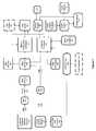
- FIG. 1is a block diagram illustrating a system for acquiring, processing and presenting data produced by one or more devices and meters in the field.
- FIG. 2illustrates an example user interface showing a hierarchical view of key performance data, such as production and pressure.
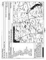
- FIG. 3illustrates an example user interface showing a mapping interface which may present wells, compressors, tanks, or other device types that have been entered into the system.
- One or more serverssuch as Supervisory Control And Data Acquisition (SCADA) servers, gather and store data from the one or more field devices or meters.
- SCADASupervisory Control And Data Acquisition
- RPIRemote polling interfaces
- Data gathered from a plurality of heterogeneous SCADA serversare normalized according to a common set of device-agnostic data types and data values, and are consolidated into one or more databases for subsequent processing by one or more computers, for storage on one or more computer-readable media, and/or for presentation using visual displays or other graphical representations.
- the systems and methodsthereby provide for collecting and unifying data from a plurality of heterogeneous sources into a device-agnostic and unified presentation for user viewing and interaction.
- FIG. 1illustrates a system in accordance with an embodiment of the present invention.
- one or more polling serverspoll one or more field devices or meters for values (not shown in FIG. 1 ).
- Field devices and metersare typically situated in remote locations and may be battery or solar powered.
- Field devicesmay communicate with polling servers using a wireless communication network, frame relay data lines, modems, or other such forms of communication.
- the polling serverssend the polled data values to one or more SCADA servers 110 .
- the SCADA serversare thereby able to gather data in real time from remote locations in order to monitor or control equipment and conditions.
- SCADA servers 102reside at customer sites and on customers' own private networks.
- the polled datamay comprise a variety of information such as meter flow, meter pressure, device battery voltage, device temperature, and the like. Polled data values have identifiers which identify the particular meter or device that originated the particular piece of data, a numerical value indicating the actual measured quantity, and a time stamp indicating the time of the measurement.
- the polling enginescomprise logic for obtaining this data from the field meters and field devices.
- the SCADA servers 110in turn obtain this data from the polling engines.
- One or more Remote Polling Interfaces (RPI) 104are configured to communicate with the one or more SCADA servers 110 .
- An RPI 104comprises software running on an application server which communicates with a SCADA 110 server. This level of indirection from the field meters and devices to the RPIs 104 exists because the operators of the RPIs 104 may not necessarily have access to the actual devices and meters out in the field. There may be various owners, operators or working interests who may not be interested in allowing unrestricted third-party access to their hardware devices out in the field. However, such owners, operators or working interests do interface with their devices and meters via one or more polling engines which store polled data values into their own internal memory or database. The operators of the RPIs 104 receive permission to extract data values out of such polling engine databases.
- An RPI 104preferably provides a secure transport mechanism (for example using a cryptographically secured communication protocol) for SCADA data and initiates the data polling from the SCADA servers 110 with which it communicates.
- An RPI 104can integrate data from a plurality of heterogeneous SCADA servers 110 and facilitate consolidation of that data into one database.
- the techniques of the present inventionare not limited to communicating and interfacing with SCADA servers 110 .
- the presented techniqueswork with any server that stores data and allows the export of such data to an RPI 104 for the gathering and consolidation of such data, as described herein.
- an RPI 104periodically wakes up and makes requests of one or more SCADA servers 110 for new data values since the last request.
- the RPI 104packages the data into a pre-determined format, for example in an eXtensible Markup Language (XML) format (if the data is not already in such format).
- XMLeXtensible Markup Language
- This binding of the received data to its origin (i.e. to the originating SCADA servers, or to the originating field meters or devices) and the packaging of the dataare herein referred to as “snapshotting” the data.
- the packaged datais for consumption by one or more data handlers 106 .
- the RPI 104optionally further compresses and encrypts the received data prior to sending the data to a data center via a secure transport, such as via a secure web service provider 111 .
- an operations center 150is provided to serve as an internal administrative tool for the setup and configuration of new devices or meter in the field.
- technicians at the operations center 150store into an XML file (or other suitable storage or format) information about the device or meter (for example device or meter ID, device or meter location, device or meter owner, etc.), the type of data values originating from the device or meter, any identifying tags that are to be associated with data values originating from that device or meter.
- the type of the incoming datais stored in a configuration database 130 and is associated with the device or meter.
- Thisallows future interpretation and tagging of incoming data values from that particular device or meter.
- thisallows the present embodiments to operate in a device or meter-agnostic fashion and gather and process data originating from a heterogeneous set of field meters and devices.
- incoming dataarrives, it is accompanied by sufficient information to indicate not just the data values, but also time stamps and data origin.
- the reverse processingis performed on the data: the data is decrypted and uncompressed (if needed) and is subsequently consumed by one or more data handlers 106 .
- Data handlers 106process the incoming data to determine which one or more customers are to receive the data. This information is indicated in a master configuration database 130 . Once a data handler 106 determines the customers, it simply writes the data into the corresponding customer databases 120 . Optionally, once a data handler 106 processes received data, it also creates a backup 107 of it.
- incoming data valuescomprise an ID identifying the originating device, a data value, and a time stamp.
- An IDmay comprise a serial number for the originating device or meter, or any other suitable identifier uniquely identifying the device or meter.
- the device IDis used to look up, in the master configuration database 130 , any tags that are to be applied to the data originating at this device. Such tags describe the types of the data values.
- a field device with ID # 1234may produce the incoming data value 25 accompanied by a time stamp of Jan. 1, 2008, 10 am. Looking up this ID in the database 130 , as well as any subsequent lookups in customer database 120 , may indicate for example that the device identified by ID # 1234 produces data values that indicate pump pressure. From this information, it is concluded that the incoming data indicates a pressure of 25 psi at pump # 1234 at 10 am on Jan. 1, 2008.
- the databasealso indicates the customers associated with a particular device, based on the device ID. This allows incoming data values to be grouped by customer, allowing the customer to view all or portions of their device data via one convenient user interface over a secure network, such as served by a secure web server over the Internet or over a private network, as further described below.
- Values obtained from the fieldare tagged according to their general data type, even when they originate from different meters with different configurations or manufacturers. For example, battery voltages coming in from the field on particular meters manufactured by different manufacturers may differ in their incoming format, but they may be tagged as a certain battery “type” to provide consistency. As another example, a first meter manufactured by a first manufacturer may refer to the flow for the previous day as “Production Yesterday,” while a second meter manufactured by a second manufacturer may refer to the same flow for the previous day differently as “Previous Data Flow,” but they may be consistently tagged as “Previous Day Flow” in order to standardize the incoming data.
- Such data “type” tagsprovide a consistent set of data types for the data set and thereby create a context for the gathered pieces of incoming data. This allows for type-based aggregations, comparisons and/or analyses to be performed on data coming in from a wide range of meters in an “apples to apples” manner that provides data consistency and makes such aggregations, comparisons and/or analyses meaningful. This is referred to herein as “data normalization” and adds business knowledge to otherwise raw data coming in from the field. Data normalization, as referred to herein, provides a context for supporting and making higher-level business decisions that conventional meter-centric systems do not provide.
- a data handler 106validates the incoming data to sift out corrupted data, such as a ⁇ 5,000,000 psi pressure reading on a pump in the field.
- a server 140serves a set of one or more user interfaces 141 , such as comprising web pages or other user interface technology as known to those of skill in the art.
- the server 140provides a web-based application for users to view and interact with the data. Users may view with the visual presentation using a computer display or screen or other visual presentation devices, and may interact with the data using computer keyboards, computer mice, touch screens, or any other input devices, as should be obvious to those of ordinary skill in the art.
- the embodiments of the present inventionprovide a higher-level view of the customers' data. While a conventional meter-centric user interface presents data from one meter at a time, the present embodiments provide group-centric or hierarchy-centric data views. This provides group-level collections of meters or devices and allows users to see data at the field-level or at the division-level with respect to the customer's business hierarchy. Such a business hierarchy may comprise parent companies, child companies, subsidiaries, divisions, and so forth.
- FIG. 2illustrates an example “Rollup Variance” user interface, showing a hierarchical view of key performance data, such as production and pressure, which can be used for surveillance and/or for drill-down reviews. Variance analysis can be performed against prior period averages and/or against imported corporate targets. When a variance is noted, the user may quickly drill down from field to well to device in order to identify and resolve the problem.
- key performance datasuch as production and pressure
- FIG. 3illustrates an example “Mapping Interface” user interface.
- Wells, compressors, tanks, or other device typeswhose locations have been entered into the system will be available on the map view.
- the locationsmay be entered using Global Positioning System (GPS) coordinates, or using any other known methods for indicating locations on a geographical map.
- GPSGlobal Positioning System
- the Mapping Interfacedisplays key performance data when a user mouses over, or otherwise indicates, a corresponding icon or designator (such as a pushpin icon) on the map.
- An advantageous result of the above data processingis that many details involved in the collection of field data are abstracted from the users who view the data. Such details include the particulars of the data centers that house the data values, particular differences between field devices and field meters manufactured by different manufacturers, particular pieces of hardware or software or protocols involved in getting the data values from the field to the databases, etc. This is in contrast to conventional systems that are hardware specific, polling interface or polling driver specific, or otherwise specific to particular technologies or origins or transports which, while present, are not of primary interest to a user who is primarily interested in gaining visibility into the data.
- a report engine 160uses information stored in the customer databases 120 to import or export data. This allows distribution of customized reports to customers based on data from associated customer databases 120 .
- the reportmay be based on normalized data, as described above, thereby allowing the report to group and present similar data consistently and thereby provide a standardized and unified view. Normalized data may be characterized based upon oil and gas contract day.
- An alarm engine 170references an alarm engine database 171 indicating one or more triggers for customer notification, such as one or more user-configured setpoints indicating trigger or alarm conditions based on the data.
- the alarm engine 170causes a notification to be sent out.
- the alarm engine 170may cause an email server 172 to send one or more email messages to customers alerting them to the fact that one or more trigger conditions have been activated.
- alarm engine 170may use a voice callout mechanism 173 (e.g. a text-to-speech robotic voice service) to communicate the trigger activation to the customer, or may generate fax messages, text messages, or other types of notification.
- a voice callout mechanism 173e.g. a text-to-speech robotic voice service
- data handlers 106process and insert data into customer databases 120 , they invoke logic that checks whether the data that is about to be inserted into a database is outside of set alarm thresholds. If so, the data handler 106 communicates that with the alarm engine 170 . In one embodiment, the data handlers 106 and the alarm engine 170 communicate via a database, with the data handlers 106 inserting events into the database which indicate incoming values that are outside of alarm thresholds, and the alarm engine 170 periodically checks the database for new database entries and processes their alarms. Some alarm examples include battery voltage thresholds, pressure thresholds, and flow-rate thresholds.
- a data processor 180comprises a number of processes for continually processing the incoming data.
- One such processis the meta tag engine 181 .
- the meta tag engine 181stores and generates data about incoming data values. Examples of tags include battery level, flow rate, pressure, tubing, casing, etc.
- the meta tag engine 181inspects the values and determines whether the values should be included in a computation. Examples of such computations include historic measurements such as periodic low, average values or high/low values.
- Other such enginesmay include a calculated tag engine, for performing configurable calculations based on associated tag values and storing the results as calculated tags, thereby providing historical rollup and/or other statistical or aggregate values.
- a communications monitor enginefor monitoring a given customer's data and sending alerts when such data has become stale or has not been updated in a predetermined period of time, thereby proactively alerting the system and/or operators of the system when expected data updates are not being received. Such alerts typically point to potential issues in the field.
- a tagmay periodically summarize incoming pressure values into a daily low, average and high value for pressure. Such tags save the effort of recomputing such values at later dates. The period of such tag computations may depend on service level agreements with customers for particular meters or devices in the field.
- a statistical analysis engineperforms predictive root cause analysis on incoming data.
- the statistical analysis engineconsiders historical data and/or signatures, and assigns probabilities to the presence of problems at particular meters in the field.
- the analysis engineis designed to detect common well problems such as well loading, low flow due to pressure interference, and well loading from fill.
- the statistical analysis engineallows a user to specify one or more of: a physical scope, a monitoring time series, an application scope, and an application scope for the analysis. These will be presently described.
- the physical scope of an analysismay be for a device, a group of devices, a field, or for other such collections of devices.
- the time series specificationmay be for a raw data capture frequency, such as per data tick, hourly, daily, weekly, or other such interval, thereby normalizing the data according to a chosen time interval.
- a capture rollup operatormay be used, examples of which include taking the minimum, maximum, sum, or average of the captured data.
- the frequency of the time series itselfmay be specified as well, for example by having the time series be captured on an hourly, daily, monthly, or other interval basis.
- One or more parametersmay be specified for the time series, with example parameters including pressure, volume, ratio of pressure to volume, or other such parameters.
- Time series start and end pointsmay be specified as well.
- Starting pointsmay be specified in terms of absolute date and time, or in terms of a specified number of intervals ago.
- End timesmay be specified in terms of absolute date and time as well, or in terms of a specified number of intervals ago, or be marked by the last data point.
- the usermay specify which results of the time series are to be monitored and optionally visually represented (for example plotted graphically and displayed on a monitor).
- Such definitionsmay be named and saved for subsequent reference. Note that such a specification may comprise a single data point, or a plurality of data points.
- the usermay further specify a comparison basis, which may be another time series or a set of absolute numbers. Once a comparison basis is specified, the user may further select a standard of difference, which may be comprise an absolute difference, a percent increase, a percent decrease, or a probability of difference. Lastly, the user may choose one or more alarm types and parameters to be triggered by the statistical analysis engine. The statistical analysis engine may then be activated with the specified parameters.
- the systemcomprises one or more live data and control servers 190 for allowing users of the system to write data back into field meters or devices, thereby providing control over the operation of field devices.
- live data and control servers 190for allowing users of the system to write data back into field meters or devices, thereby providing control over the operation of field devices.
- remote controlling of meters in the fieldcan be done via an interface provided by one or more web servers to users.
- one or more SCADA serverscan be communicated with and controlled via a unified web interface, thereby unifying the monitoring and control of SCADA servers and field meters.
- Such computer systemsmay comprise memory elements for storing instructions read from computer readable media and executable by a processor or other such controller.
- the computer systemsmay comprise communication subsystems for communicating with other systems over wired or wireless connections, as well as input/output (I/O) devices such as computer keyboards, computer mice, track balls, pointing devices, computer displays or screens, graphics subsystems, printers, and any other such peripheral devices or systems as should be known to those of ordinary skill in the art.
- I/Oinput/output
- the present systemsmay communicate with mobile devices to get input from user and/or to provide the above-described visual, textual, or auditory outputs to users.
Landscapes
- Engineering & Computer Science (AREA)
- Business, Economics & Management (AREA)
- Theoretical Computer Science (AREA)
- Physics & Mathematics (AREA)
- General Physics & Mathematics (AREA)
- Strategic Management (AREA)
- Economics (AREA)
- Human Resources & Organizations (AREA)
- General Business, Economics & Management (AREA)
- Tourism & Hospitality (AREA)
- Databases & Information Systems (AREA)
- Entrepreneurship & Innovation (AREA)
- Marketing (AREA)
- Quality & Reliability (AREA)
- Animal Husbandry (AREA)
- Operations Research (AREA)
- Educational Administration (AREA)
- Development Economics (AREA)
- Automation & Control Theory (AREA)
- Manufacturing & Machinery (AREA)
- Life Sciences & Earth Sciences (AREA)
- Agronomy & Crop Science (AREA)
- Game Theory and Decision Science (AREA)
- Marine Sciences & Fisheries (AREA)
- Mining & Mineral Resources (AREA)
- Health & Medical Sciences (AREA)
- General Health & Medical Sciences (AREA)
- Primary Health Care (AREA)
- Human Computer Interaction (AREA)
- Data Mining & Analysis (AREA)
- General Engineering & Computer Science (AREA)
- Arrangements For Transmission Of Measured Signals (AREA)
- Selective Calling Equipment (AREA)
Abstract
Description
Claims (20)
Priority Applications (2)
| Application Number | Priority Date | Filing Date | Title |
|---|---|---|---|
| US12/359,146US8301386B1 (en) | 2009-01-23 | 2009-01-23 | Classification and web-based presentation of oil and gas SCADA data |
| PCT/US2010/021471WO2010085468A2 (en) | 2009-01-23 | 2010-01-20 | Classification and web-based presentation of oil and gas scada data |
Applications Claiming Priority (1)
| Application Number | Priority Date | Filing Date | Title |
|---|---|---|---|
| US12/359,146US8301386B1 (en) | 2009-01-23 | 2009-01-23 | Classification and web-based presentation of oil and gas SCADA data |
Publications (1)
| Publication Number | Publication Date |
|---|---|
| US8301386B1true US8301386B1 (en) | 2012-10-30 |
Family
ID=42356381
Family Applications (1)
| Application Number | Title | Priority Date | Filing Date |
|---|---|---|---|
| US12/359,146Expired - Fee RelatedUS8301386B1 (en) | 2009-01-23 | 2009-01-23 | Classification and web-based presentation of oil and gas SCADA data |
Country Status (2)
| Country | Link |
|---|---|
| US (1) | US8301386B1 (en) |
| WO (1) | WO2010085468A2 (en) |
Cited By (32)
| Publication number | Priority date | Publication date | Assignee | Title |
|---|---|---|---|---|
| US8649909B1 (en) | 2012-12-07 | 2014-02-11 | Amplisine Labs, LLC | Remote control of fluid-handling devices |
| US20150112989A1 (en)* | 2013-10-21 | 2015-04-23 | Honeywell International Inc. | Opus enterprise report system |
| US20160026678A1 (en)* | 2014-07-28 | 2016-01-28 | Schlumberger Technology Corporation | System and method of facilitating oilfield data analysis |
| US20160085972A1 (en)* | 2014-09-23 | 2016-03-24 | Accenture Global Services Limited | Industrial security agent platform |
| US20160142514A1 (en)* | 2014-11-19 | 2016-05-19 | Itron, Inc. | Application Platform Operable on Network Node |
| US9835662B2 (en) | 2014-12-02 | 2017-12-05 | Itron, Inc. | Electrical network topology determination |
| US9852387B2 (en) | 2008-10-28 | 2017-12-26 | Honeywell International Inc. | Building management system site categories |
| US9924242B2 (en) | 2012-04-20 | 2018-03-20 | Itron Global Sarl | Automatic network topology detection and fraud detection |
| US9933762B2 (en) | 2014-07-09 | 2018-04-03 | Honeywell International Inc. | Multisite version and upgrade management system |
| US10209689B2 (en) | 2015-09-23 | 2019-02-19 | Honeywell International Inc. | Supervisor history service import manager |
| US10209283B2 (en) | 2014-10-20 | 2019-02-19 | Itron, Inc. | Electrical phase identification |
| US10289086B2 (en) | 2012-10-22 | 2019-05-14 | Honeywell International Inc. | Supervisor user management system |
| US10312681B2 (en) | 2015-05-28 | 2019-06-04 | Itron, Inc. | Automatic network device electrical phase identification |
| US10362104B2 (en) | 2015-09-23 | 2019-07-23 | Honeywell International Inc. | Data manager |
| RU2706587C1 (en)* | 2018-09-25 | 2019-11-19 | Дмитрий Валерьевич Хачатуров | Digital data collection, processing, storage and transmission system and method |
| US10571493B2 (en) | 2014-02-25 | 2020-02-25 | Itron, Inc. | Smart grid topology estimator |
| WO2020068027A1 (en)* | 2018-09-25 | 2020-04-02 | Дмитрий Валерьевич ХАЧАТУРОВ | System and method for processing, storing and transmitting digital data |
| US10705499B2 (en) | 2018-03-30 | 2020-07-07 | Schlumberger Technology Corporation | System and method for automated shutdown and startup for a network |
| US10761509B2 (en) | 2017-06-23 | 2020-09-01 | Honeywell International Inc. | Efficient method and system for automatically generating data points in a SCADA system |
| US10782679B2 (en) | 2016-12-15 | 2020-09-22 | Schlumberger Technology Corporation | Relationship tagging of data in well construction |
| US10890060B2 (en) | 2018-12-07 | 2021-01-12 | Schlumberger Technology Corporation | Zone management system and equipment interlocks |
| US10907466B2 (en) | 2018-12-07 | 2021-02-02 | Schlumberger Technology Corporation | Zone management system and equipment interlocks |
| US10920562B2 (en) | 2017-11-01 | 2021-02-16 | Schlumberger Technology Corporation | Remote control and monitoring of engine control system |
| US11016457B1 (en) | 2019-07-19 | 2021-05-25 | zdSCADA, LP | Supervisory control and data acquisition (SCADA) system for use with SCADA devices having disparate communication technologies |
| US11021944B2 (en) | 2017-06-13 | 2021-06-01 | Schlumberger Technology Corporation | Well construction communication and control |
| US11079417B2 (en) | 2014-02-25 | 2021-08-03 | Itron, Inc. | Detection of electric power diversion |
| US11143010B2 (en) | 2017-06-13 | 2021-10-12 | Schlumberger Technology Corporation | Well construction communication and control |
| US11215045B2 (en) | 2015-11-04 | 2022-01-04 | Schlumberger Technology Corporation | Characterizing responses in a drilling system |
| US11422999B2 (en) | 2017-07-17 | 2022-08-23 | Schlumberger Technology Corporation | System and method for using data with operation context |
| US11514383B2 (en) | 2019-09-13 | 2022-11-29 | Schlumberger Technology Corporation | Method and system for integrated well construction |
| US12055027B2 (en) | 2020-03-06 | 2024-08-06 | Schlumberger Technology Corporation | Automating well construction operations based on detected abnormal events |
| US12366152B2 (en) | 2018-06-04 | 2025-07-22 | Schlumberger Technology Corporation | Well construction workstation and control |
Families Citing this family (2)
| Publication number | Priority date | Publication date | Assignee | Title |
|---|---|---|---|---|
| WO2012130586A1 (en)* | 2011-03-30 | 2012-10-04 | Siemens Aktiengesellschaft | Apparatus and method for operating analysis and/or optimization of a technical system |
| KR102544578B1 (en) | 2016-03-07 | 2023-06-15 | 엘에스일렉트릭(주) | Controlling method of data display apparatus |
Citations (6)
| Publication number | Priority date | Publication date | Assignee | Title |
|---|---|---|---|---|
| WO1999039276A1 (en) | 1998-01-15 | 1999-08-05 | Eutech Cybernetics Pte Ltd. | Method and apparatus for the creation of personalized supervisory and control data acquisition systems for the management and integration of real-time enterprise-wide applications and systems |
| WO2001099078A2 (en) | 2000-06-20 | 2001-12-27 | Eutech Cybernetics, Inc. | Remote real-time data monitoring and control system |
| US20020147503A1 (en) | 2001-04-05 | 2002-10-10 | Osburn Douglas C. | Remote terminal unit |
| US20020147808A1 (en) | 2001-04-05 | 2002-10-10 | Osburn Douglas C. | Integrated automation system |
| US20050007249A1 (en)* | 1999-02-22 | 2005-01-13 | Evren Eryurek | Integrated alert generation in a process plant |
| US20070050157A1 (en)* | 2005-06-10 | 2007-03-01 | Sensicore, Inc. | Systems and methods for fluid quality sensing, data sharing and data visualization |
- 2009
- 2009-01-23USUS12/359,146patent/US8301386B1/ennot_activeExpired - Fee Related
- 2010
- 2010-01-20WOPCT/US2010/021471patent/WO2010085468A2/enactiveApplication Filing
Patent Citations (19)
| Publication number | Priority date | Publication date | Assignee | Title |
|---|---|---|---|---|
| EP1047998A4 (en) | 1998-01-15 | 2005-01-05 | Eutech Cybernetics Pte Ltd | Method and apparatus for the creation of personalized supervisory and control data acquisition systems for the management and integration of real-time enterprise-wide applications and systems |
| US6571140B1 (en) | 1998-01-15 | 2003-05-27 | Eutech Cybernetics Pte Ltd. | Service-oriented community agent |
| US6067477A (en)* | 1998-01-15 | 2000-05-23 | Eutech Cybernetics Pte Ltd. | Method and apparatus for the creation of personalized supervisory and control data acquisition systems for the management and integration of real-time enterprise-wide applications and systems |
| US6477434B1 (en)* | 1998-01-15 | 2002-11-05 | Bandu Wewalaarachchi | Method and apparatus for the creation of personalized supervisory and control data acquisition systems for the management and integration of real-time enterprise-wide applications and systems |
| CN1293780A (en) | 1998-01-15 | 2001-05-02 | 尤泰克控制论私人有限公司 | Method and apparatus for creating a personalized monitoring and control data acquisition system |
| WO1999039276A1 (en) | 1998-01-15 | 1999-08-05 | Eutech Cybernetics Pte Ltd. | Method and apparatus for the creation of personalized supervisory and control data acquisition systems for the management and integration of real-time enterprise-wide applications and systems |
| JP2002502072A (en) | 1998-01-15 | 2002-01-22 | ユーテク サイバーネティクス プライベート リミティド | Method and apparatus for creating a dedicated monitoring and control data collection system for managing and integrating enterprise real-time applications and systems |
| EP1047998A1 (en) | 1998-01-15 | 2000-11-02 | Eutech Cybernetics Pte Ltd. | Method and apparatus for the creation of personalized supervisory and control data acquisition systems for the management and integration of real-time enterprise-wide applications and systems |
| CA2317493A1 (en) | 1998-01-15 | 1999-08-05 | Haritharan Gunasingham | Method and apparatus for the creation of personalized supervisory and control data acquisition systems for the management and integration of real-time enterprise-wide applicationsand systems |
| US20050007249A1 (en)* | 1999-02-22 | 2005-01-13 | Evren Eryurek | Integrated alert generation in a process plant |
| WO2001099078A2 (en) | 2000-06-20 | 2001-12-27 | Eutech Cybernetics, Inc. | Remote real-time data monitoring and control system |
| US20020147503A1 (en) | 2001-04-05 | 2002-10-10 | Osburn Douglas C. | Remote terminal unit |
| US6628992B2 (en) | 2001-04-05 | 2003-09-30 | Automation Solutions, Inc. | Remote terminal unit |
| US20020147808A1 (en) | 2001-04-05 | 2002-10-10 | Osburn Douglas C. | Integrated automation system |
| US6950851B2 (en) | 2001-04-05 | 2005-09-27 | Osburn Iii Douglas C | System and method for communication for a supervisory control and data acquisition (SCADA) system |
| US6961753B1 (en) | 2001-04-05 | 2005-11-01 | Osburn Iii Douglas C | Enterprise server for communication for a supervisory control and data acquisition (SCADA) System |
| US7225248B1 (en) | 2001-04-05 | 2007-05-29 | Dj Inventions, Llc | Integrated automation system with publisher interface |
| US20070050157A1 (en)* | 2005-06-10 | 2007-03-01 | Sensicore, Inc. | Systems and methods for fluid quality sensing, data sharing and data visualization |
| US7424399B2 (en) | 2005-06-10 | 2008-09-09 | Ge Analytical Instruments, Inc. | Systems and methods for fluid quality sensing, data sharing and data visualization |
Cited By (46)
| Publication number | Priority date | Publication date | Assignee | Title |
|---|---|---|---|---|
| US10565532B2 (en) | 2008-10-28 | 2020-02-18 | Honeywell International Inc. | Building management system site categories |
| US9852387B2 (en) | 2008-10-28 | 2017-12-26 | Honeywell International Inc. | Building management system site categories |
| US10327048B2 (en) | 2012-04-20 | 2019-06-18 | Itron Global Sarl | Automatic network topology detection and fraud detection |
| US9924242B2 (en) | 2012-04-20 | 2018-03-20 | Itron Global Sarl | Automatic network topology detection and fraud detection |
| US10289086B2 (en) | 2012-10-22 | 2019-05-14 | Honeywell International Inc. | Supervisor user management system |
| US12321184B2 (en) | 2012-12-07 | 2025-06-03 | Sitepro, Inc. | Remote control of fluid-handling devices |
| US8649909B1 (en) | 2012-12-07 | 2014-02-11 | Amplisine Labs, LLC | Remote control of fluid-handling devices |
| US20150112989A1 (en)* | 2013-10-21 | 2015-04-23 | Honeywell International Inc. | Opus enterprise report system |
| US9971977B2 (en)* | 2013-10-21 | 2018-05-15 | Honeywell International Inc. | Opus enterprise report system |
| US10571493B2 (en) | 2014-02-25 | 2020-02-25 | Itron, Inc. | Smart grid topology estimator |
| US11079417B2 (en) | 2014-02-25 | 2021-08-03 | Itron, Inc. | Detection of electric power diversion |
| US10338550B2 (en) | 2014-07-09 | 2019-07-02 | Honeywell International Inc. | Multisite version and upgrade management system |
| US9933762B2 (en) | 2014-07-09 | 2018-04-03 | Honeywell International Inc. | Multisite version and upgrade management system |
| US20160026678A1 (en)* | 2014-07-28 | 2016-01-28 | Schlumberger Technology Corporation | System and method of facilitating oilfield data analysis |
| US9870476B2 (en)* | 2014-09-23 | 2018-01-16 | Accenture Global Services Limited | Industrial security agent platform |
| US20180144144A1 (en)* | 2014-09-23 | 2018-05-24 | Accenture Global Services Limited | Industrial security agent platform |
| US9864864B2 (en)* | 2014-09-23 | 2018-01-09 | Accenture Global Services Limited | Industrial security agent platform |
| US10824736B2 (en)* | 2014-09-23 | 2020-11-03 | Accenture Global Services Limited | Industrial security agent platform |
| US20160087958A1 (en)* | 2014-09-23 | 2016-03-24 | Accenture Global Services Limited | Industrial security agent platform |
| US20160085972A1 (en)* | 2014-09-23 | 2016-03-24 | Accenture Global Services Limited | Industrial security agent platform |
| US10209283B2 (en) | 2014-10-20 | 2019-02-19 | Itron, Inc. | Electrical phase identification |
| US9781231B2 (en)* | 2014-11-19 | 2017-10-03 | Itron, Inc. | Application platform operable on network node |
| US20160142514A1 (en)* | 2014-11-19 | 2016-05-19 | Itron, Inc. | Application Platform Operable on Network Node |
| US10459016B2 (en) | 2014-12-02 | 2019-10-29 | Itron, Inc. | Electrical network topology determination |
| US9835662B2 (en) | 2014-12-02 | 2017-12-05 | Itron, Inc. | Electrical network topology determination |
| US10312681B2 (en) | 2015-05-28 | 2019-06-04 | Itron, Inc. | Automatic network device electrical phase identification |
| US10362104B2 (en) | 2015-09-23 | 2019-07-23 | Honeywell International Inc. | Data manager |
| US10209689B2 (en) | 2015-09-23 | 2019-02-19 | Honeywell International Inc. | Supervisor history service import manager |
| US10951696B2 (en) | 2015-09-23 | 2021-03-16 | Honeywell International Inc. | Data manager |
| US11215045B2 (en) | 2015-11-04 | 2022-01-04 | Schlumberger Technology Corporation | Characterizing responses in a drilling system |
| US10782679B2 (en) | 2016-12-15 | 2020-09-22 | Schlumberger Technology Corporation | Relationship tagging of data in well construction |
| US11795805B2 (en) | 2017-06-13 | 2023-10-24 | Schlumberger Technology Corporation | Well construction communication and control |
| US11021944B2 (en) | 2017-06-13 | 2021-06-01 | Schlumberger Technology Corporation | Well construction communication and control |
| US11143010B2 (en) | 2017-06-13 | 2021-10-12 | Schlumberger Technology Corporation | Well construction communication and control |
| US10761509B2 (en) | 2017-06-23 | 2020-09-01 | Honeywell International Inc. | Efficient method and system for automatically generating data points in a SCADA system |
| US11422999B2 (en) | 2017-07-17 | 2022-08-23 | Schlumberger Technology Corporation | System and method for using data with operation context |
| US10920562B2 (en) | 2017-11-01 | 2021-02-16 | Schlumberger Technology Corporation | Remote control and monitoring of engine control system |
| US10705499B2 (en) | 2018-03-30 | 2020-07-07 | Schlumberger Technology Corporation | System and method for automated shutdown and startup for a network |
| US12366152B2 (en) | 2018-06-04 | 2025-07-22 | Schlumberger Technology Corporation | Well construction workstation and control |
| WO2020068027A1 (en)* | 2018-09-25 | 2020-04-02 | Дмитрий Валерьевич ХАЧАТУРОВ | System and method for processing, storing and transmitting digital data |
| RU2706587C1 (en)* | 2018-09-25 | 2019-11-19 | Дмитрий Валерьевич Хачатуров | Digital data collection, processing, storage and transmission system and method |
| US10907466B2 (en) | 2018-12-07 | 2021-02-02 | Schlumberger Technology Corporation | Zone management system and equipment interlocks |
| US10890060B2 (en) | 2018-12-07 | 2021-01-12 | Schlumberger Technology Corporation | Zone management system and equipment interlocks |
| US11016457B1 (en) | 2019-07-19 | 2021-05-25 | zdSCADA, LP | Supervisory control and data acquisition (SCADA) system for use with SCADA devices having disparate communication technologies |
| US11514383B2 (en) | 2019-09-13 | 2022-11-29 | Schlumberger Technology Corporation | Method and system for integrated well construction |
| US12055027B2 (en) | 2020-03-06 | 2024-08-06 | Schlumberger Technology Corporation | Automating well construction operations based on detected abnormal events |
Also Published As
| Publication number | Publication date |
|---|---|
| WO2010085468A2 (en) | 2010-07-29 |
| WO2010085468A3 (en) | 2010-11-04 |
Similar Documents
| Publication | Publication Date | Title |
|---|---|---|
| US8301386B1 (en) | Classification and web-based presentation of oil and gas SCADA data | |
| US12099468B2 (en) | Systems and methods for collecting, analyzing, billing, and reporting data from intelligent electronic devices | |
| US20090070168A1 (en) | Enterprise energy management system with social network approach to data analysis | |
| JP6318307B2 (en) | System and method for resource consumption analysis | |
| US8065342B1 (en) | Method and system for monitoring a mobile equipment fleet | |
| US11258855B2 (en) | System and method for analyzing and monitoring smart meter network communications | |
| US9059898B2 (en) | System and method for tracking configuration changes in enterprise product | |
| US20190196795A1 (en) | Automated streaming data model generation | |
| US20180132015A1 (en) | Integrated Solution of Internet of Things and Smart Grid Network Pertaining to Communication, Data and Asset Serialization, and Data Modeling Algorithms | |
| US20030110249A1 (en) | System and method for monitoring key performance indicators in a business | |
| US20130151979A1 (en) | System and method for enterprise utility data aggregation, management, and reporting | |
| US20190086452A1 (en) | Systems and methods for managing resource consumption | |
| US10162344B2 (en) | Mechanism and approach for monitoring building automation systems through user defined content notifications | |
| WO2016049369A1 (en) | Utilizing machine learning to identify non-technical loss | |
| US20190086878A1 (en) | Systems and methods for determining baseline consumption | |
| US11063998B2 (en) | System and method for energy management information system reliability assurance | |
| US20070100900A1 (en) | Apparatus for remote monitoring of equipment, with feed for feeding data | |
| Patabendige et al. | Detection and interpretation of anomalous water use for non-residential customers | |
| CN116028543A (en) | Fusion collaboration system and method for mine multielement information | |
| US20250013603A1 (en) | Systems and methods for collecting, analyzing, billing, and reporting data from intelligent electronic devices | |
| US20100070890A1 (en) | Method for Providing a Manufacturing Execution System (MES) Service to Third Parties | |
| US9625613B2 (en) | Weather determination system and method | |
| US9177399B2 (en) | Method and system for plotting a distribution of data | |
| WO2021097041A1 (en) | Operational anomaly feedback loop system and method | |
| CN116401138B (en) | Operating system running state detection method and device, electronic equipment and medium |
Legal Events
| Date | Code | Title | Description |
|---|---|---|---|
| AS | Assignment | Owner name:ELYNX TECHNOLOGIES, LLC, OKLAHOMA Free format text:ASSIGNMENT OF ASSIGNORS INTEREST;ASSIGNORS:REDMOND, DOUG;MCDANIEL, RAY;SALLEE, DUANE;REEL/FRAME:022150/0743 Effective date:20090123 | |
| ZAAA | Notice of allowance and fees due | Free format text:ORIGINAL CODE: NOA | |
| ZAAB | Notice of allowance mailed | Free format text:ORIGINAL CODE: MN/=. | |
| STCF | Information on status: patent grant | Free format text:PATENTED CASE | |
| FPAY | Fee payment | Year of fee payment:4 | |
| MAFP | Maintenance fee payment | Free format text:PAYMENT OF MAINTENANCE FEE, 8TH YR, SMALL ENTITY (ORIGINAL EVENT CODE: M2552); ENTITY STATUS OF PATENT OWNER: SMALL ENTITY Year of fee payment:8 | |
| FEPP | Fee payment procedure | Free format text:MAINTENANCE FEE REMINDER MAILED (ORIGINAL EVENT CODE: REM.); ENTITY STATUS OF PATENT OWNER: SMALL ENTITY | |
| LAPS | Lapse for failure to pay maintenance fees | Free format text:PATENT EXPIRED FOR FAILURE TO PAY MAINTENANCE FEES (ORIGINAL EVENT CODE: EXP.); ENTITY STATUS OF PATENT OWNER: SMALL ENTITY | |
| STCH | Information on status: patent discontinuation | Free format text:PATENT EXPIRED DUE TO NONPAYMENT OF MAINTENANCE FEES UNDER 37 CFR 1.362 | |
| FP | Lapsed due to failure to pay maintenance fee | Effective date:20241030 |