US8301004B2 - Fiber optic cable assemblies employing a furcation body having anti-rotation feature - Google Patents
Fiber optic cable assemblies employing a furcation body having anti-rotation featureDownload PDFInfo
- Publication number
- US8301004B2 US8301004B2US12/417,325US41732509AUS8301004B2US 8301004 B2US8301004 B2US 8301004B2US 41732509 AUS41732509 AUS 41732509AUS 8301004 B2US8301004 B2US 8301004B2
- Authority
- US
- United States
- Prior art keywords
- furcation
- fiber optic
- furcation body
- optic cable
- attachment
- Prior art date
- Legal status (The legal status is an assumption and is not a legal conclusion. Google has not performed a legal analysis and makes no representation as to the accuracy of the status listed.)
- Active, expires
Links
- 239000000835fiberSubstances0.000titleclaimsabstractdescription298
- 230000000712assemblyEffects0.000titledescription61
- 238000000429assemblyMethods0.000titledescription61
- 230000000295complement effectEffects0.000claimsabstractdescription6
- 230000001737promoting effectEffects0.000claims1
- 230000002401inhibitory effectEffects0.000description8
- 239000013307optical fiberSubstances0.000description6
- 230000007246mechanismEffects0.000description5
- 230000008901benefitEffects0.000description4
- 238000012986modificationMethods0.000description4
- 230000004048modificationEffects0.000description4
- 230000003287optical effectEffects0.000description4
- 239000000463materialSubstances0.000description3
- 229910052751metalInorganic materials0.000description3
- 239000002184metalSubstances0.000description3
- 238000000034methodMethods0.000description3
- 239000004033plasticSubstances0.000description3
- 238000005452bendingMethods0.000description2
- 239000002131composite materialSubstances0.000description2
- 230000000717retained effectEffects0.000description2
- 239000004593EpoxySubstances0.000description1
- 229910052782aluminiumInorganic materials0.000description1
- XAGFODPZIPBFFR-UHFFFAOYSA-NaluminiumChemical compound[Al]XAGFODPZIPBFFR-UHFFFAOYSA-N0.000description1
- 230000005540biological transmissionEffects0.000description1
- 238000004891communicationMethods0.000description1
- 230000006835compressionEffects0.000description1
- 238000007906compressionMethods0.000description1
- 238000010276constructionMethods0.000description1
- 238000005516engineering processMethods0.000description1
- 230000005484gravityEffects0.000description1
- 238000009434installationMethods0.000description1
- 230000008520organizationEffects0.000description1
- 238000013519translationMethods0.000description1
Images


Classifications
- G—PHYSICS
- G02—OPTICS
- G02B—OPTICAL ELEMENTS, SYSTEMS OR APPARATUS
- G02B6/00—Light guides; Structural details of arrangements comprising light guides and other optical elements, e.g. couplings
- G02B6/44—Mechanical structures for providing tensile strength and external protection for fibres, e.g. optical transmission cables
- G02B6/4439—Auxiliary devices
- G02B6/4471—Terminating devices ; Cable clamps
- G02B6/44715—Fan-out devices
- G—PHYSICS
- G02—OPTICS
- G02B—OPTICAL ELEMENTS, SYSTEMS OR APPARATUS
- G02B6/00—Light guides; Structural details of arrangements comprising light guides and other optical elements, e.g. couplings
- G02B6/44—Mechanical structures for providing tensile strength and external protection for fibres, e.g. optical transmission cables
- G02B6/4439—Auxiliary devices
- G02B6/444—Systems or boxes with surplus lengths
- G02B6/4453—Cassettes
- G—PHYSICS
- G02—OPTICS
- G02B—OPTICAL ELEMENTS, SYSTEMS OR APPARATUS
- G02B6/00—Light guides; Structural details of arrangements comprising light guides and other optical elements, e.g. couplings
- G02B6/44—Mechanical structures for providing tensile strength and external protection for fibres, e.g. optical transmission cables
- G02B6/4439—Auxiliary devices
- G02B6/4471—Terminating devices ; Cable clamps
- G02B6/44765—Terminating devices ; Cable clamps with means for strain-relieving to exterior cable layers
Definitions
- the technology of the disclosurerelates to the management of fiber optic cable assemblies having a furcation body and structures for securing the same to fiber optic equipment.
- optical fiber useincludes extremely wide bandwidth and low noise operation. Because of these advantages, optical fiber is increasingly being used for a variety of applications, including but not limited to broadband voice, video, and data transmission. As a result, fiber optic communications networks include a number of interconnection points at which multiple optical fibers are interconnected.
- Fiber optic installationssuch as data centers, local-area networks (LAN) and the like route fiber optic cables to fiber optic equipment to establish optical connections.
- the fiber optic cablesmay be installed by pulling fiber optic cables to the equipment in cable runs under the floor, in the ceiling, or riser locations, etc.
- Preconnectorized fiber optic cable assembliesare typically furcated to separate out individual or groups of optical fibers for making optical connections at the fiber optic equipment.
- the cable assemblytypically includes a furcation assembly near an end of the cable assembly where the optical fibers are split from the fiber optic cable.
- the furcation assemblyincludes a furcation body or plug that is usually secured such as on the outside of the housing for positioning, inhibiting damage, and strain relief.
- high-density fiber optic equipment designsmay not be possible due to the inability of the fiber optic equipment to support a sufficient density of furcation assemblies.
- furcation assembly securing techniquescan be simple fasteners, such tape, a Ty-Wraps®, or Velcro® as examples, and can be used to fasten the furcation assembly to the fiber optic equipment.
- these securing techniquesmay not be easily integrated into fiber optic equipment and/or not securely mount the furcation assembly.
- changes or reconfigurations of fiber optic cables or optical connections in already installed fiber optic equipmentare necessary, it may be cumbersome to detach installed furcation assemblies and reattach them to the fiber optic equipment.
- these securing techniquesmay affect the stability and strength of the furcation assembly attachment to fiber optic equipment, including the ability of the furcation plug to withstand lateral and rotational forces.
- Fiber optic cable assemblieshaving a fiber optic cable and a furcation body.
- the fiber optic cableis received into the furcation body and furcated into one or more furcated legs inside the furcation body.
- An anti-rotation featuremay be integrated into the furcation body for inhibiting rotation of the furcation body when mounted in or to fiber optic equipment.
- An attachment featurecan also provide for inhibiting lateral movement of the furcation body when mounted in or to the fiber optic equipment.
- FIGS. 1A and 1Bare perspective views of explanatory fiber optic cable assemblies secured to a mounting surface of an exemplary fiber optic shelf assembly
- FIG. 2is a perspective view of an explanatory fiber optic cable assembly illustrated in FIGS. 1A and 1B ;
- FIG. 3Ais a perspective view of a clip for securing the fiber optic cable assembly of FIG. 2 ;
- FIG. 3Bis a perspective view of a portion of the fiber optic cable assembly of FIG. 2 ;
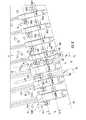
- FIG. 4illustrates multiple fiber optic cable assemblies of FIG. 2 installed on the mounting surface of the fiber optic shelf assembly of FIGS. 1A and 1B ;
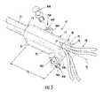
- FIG. 5is a perspective view of another exemplary fiber optic cable assembly with attachment features integrated into the furcation body
- FIG. 6is a perspective view of a fiber optic cable assembly similar to FIG. 5 without securing devices disposed in the attachment features;
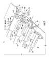
- FIG. 7is a perspective view of fiber optic cable assemblies of FIGS. 5 and 6 secured to a mounting surface of an exemplary fiber optic shelf assembly;
- FIG. 8illustrates a close-up view of FIG. 7 illustrating the fiber optic cable assemblies of FIGS. 5 and 6 secured to a mounting surface of an exemplary fiber optic shelf assembly;
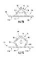
- FIGS. 9A and 9Billustrate front views of alternate furcation bodies having different cross-sectional shapes
- FIGS. 10A and 10Billustrate side and bottom perspective views, respectively, of another exemplary fiber optic cable assembly
- FIG. 11illustrates a perspective view of another exemplary fiber optic cable assembly
- FIG. 12Aillustrates a perspective view of another exemplary fiber optic cable assembly
- FIGS. 12B-12Dillustrate side, front, and bottom views, respectively, of the fiber optic cable assembly of FIG. 12A ;
- FIG. 13illustrates multiple fiber optic cable assemblies of FIGS. 12A-12D installed on a mounting surface of a fiber optic shelf assembly
- FIGS. 14A and 14Brespectively illustrate another exemplary fiber optic cable assembly and a securing device
- FIGS. 15A and 15Billustrate another exemplary fiber optic cable assembly
- FIG. 16illustrates exemplary securing devices for the fiber optic cable assembly of FIGS. 15A and 15B ;
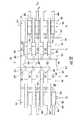
- FIG. 17is a rear perspective view of an exemplary fiber optic shelf assembly having a furcation management assembly
- FIG. 18is a close-up view of the furcation management assembly of FIG. 17 in a closed position
- FIGS. 19 and 20are different perspective close-up views of the furcation management assembly of FIG. 17 in an open position
- FIG. 21illustrates a rear perspective view of an alternate exemplary fiber optic shelf assembly having an alternate furcation management assembly
- FIG. 22illustrates a top view of the furcation tray disposed in the fiber optic shelf assembly of FIG. 21 ;
- FIG. 23illustrates a furcation platform provided in the fiber optic shelf assembly of FIG. 21 ;
- FIG. 24illustrates the furcation platform of FIG. 23 disposed as an appendage to the fiber optic shelf assembly of FIG. 21 ;
- FIG. 25illustrates a side view of the fiber optic shelf assembly of FIG. 21 including an additional top furcation tray
- FIG. 26is a side view of the fiber optic shelf assembly of FIG. 21 providing top, bottom, and intermediate furcation trays;
- FIG. 27is a perspective view of the fiber optic shelf assembly of FIG. 26 with the intermediate furcation tray translated out from the fiber optic shelf assembly.
- FIGS. 28-30depict a various views of another alternate furcation management assembly mounted in a fiber optic shelf assembly.
- FIGS. 31A-31Dare perspective views of clips for securing furcation bodies of fiber optic cable assemblies.
- Certain embodiments disclosed in the detailed descriptioninclude fiber optic cable assemblies having a fiber optic cable and a furcation body.
- the fiber optic cableis received into the furcation body and furcated into one or more legs that exit the furcation body for routing to desired locations.
- An anti-rotation featuremay be integrated into the furcation body for inhibiting rotation of the furcation body when mounted in or to fiber optic equipment.
- anti-rotation featuremeans one or more generally planar surfaces disposed on the furcation body for abutting with at least one complementary planar mounting surface.
- An attachment featurewhich may be a separate component or integrated with the furcation body inhibits lateral movement and/or rotation of the furcation body when secured in position.
- FIGS. 1A and 1Billustrate front perspective views of explanatory fiber optic equipment in the form of a fiber optic shelf assembly 10 .
- the fiber optic shelf assembly 10allows mounting of one or more fiber optic cable assemblies 12 thereto.
- fiber optic shelf assemblymay be any suitable structure for mounting one or more fiber optic cable assemblies disclosed herein.
- Several fiber optic shelf assemblies, housings, or the likeare typically mounted to an equipment rack (not shown), thereby creating a centralized location for fiber interconnections.
- fiber optic cable assemblies 12are attached to the rear portion 14 of the fiber optic shelf assembly 10 in the form of a fiber optic tray 16 .
- the fiber optic tray 16.
- the fiber optic tray 16has a 1 U size (i.e., 1.75 inches in height) and supports a fiber optic adapter module 18 , but the concepts disclosed herein may be used with any suitable mounting surface.
- the fiber optic shelf assemblyis depicted as a 1-U any size or configuration is possible such as 4-U or vertical arrangement.
- Fiber optic cable assemblies 12include one or more furcation bodies 26 having a desired number of furcated legs 28 exiting the same.
- the furcated legs 28may be of any shape, including but not limited to round or rectangular.
- the furcations of the fiber optic cables 22may be performed by the cable manufacturer in a factory setting before routing the fiber optic cable assembly 12 to the fiber optic tray 16 .
- the furcated legs 28are typically connectorized with fiber optic connectors ( FIG. 17 ) for connecting with fiber optic adapters (not visible) or the like in the rear panel 20 of the fiber optic adapter module 18 , thereby establishing fiber optic connections.
- the fiber optic cable assemblies 12are secured to the fiber optic shelf assembly 10 ; specifically, the fiber optic cable assemblies 12 are secured to the fiber optic tray 16 , and particularly to the rear portion 14 . Securing the fiber optic cable assemblies 12 to the fiber optic tray 16 prevents or reduces the chance of bending or damage to the fiber optic cables 22 and the optical fibers therein due to forces applied to the fiber optic cable assemblies 12 .
- the furcation body 26may include at least one anti-rotation feature that is integrated therewith for inhibiting rotational forces on the furcation body 26 when installed in the fiber optic shelf assembly 10 or other suitable location.
- the furcation body 26may also include one or more attachment features to inhibit lateral movement of the furcation body 26 when installed in the fiber optic shelf assembly 10 .
- the furcation bodies 26 of fiber optic cable assemblies 12are secured to a mounting surface 30 formed in the rear portion 14 of the fiber optic tray 16 . Because the fiber optic cables 22 are received in respective furcation bodies 26 and securely attached therein, securing of the respective furcation bodies 26 to the mounting surface 30 secures the respective fiber optic cables 22 to the fiber optic shelf assembly 10 .
- the fiber optic cables 22are routed through the openings 24 A, 24 B.
- the furcation bodies 26are mounted to the mounting surface 30 of the fiber optic tray 16 substantially parallel to the rear portion 14 of the fiber optic tray 16 since routing the fiber optic cables 22 through the openings 24 A, 24 B naturally aligns the furcation body 26 substantially parallel to the rear portion 14 .
- the furcation body 26can also be mounted to the mounting surface 30 of the fiber optic tray 16 in an orientation substantially orthogonal to the rear portion 14 . Of course, any suitable orientation is possible for the furcation body 26 .
- the furcation bodies 26are mounted to the mounting surface 30 such that the furcation bodies 26 do not extend above a top plane 31 of the fiber optic tray 16 .
- the furcation bodies 26are mounted in a low profile manner to the mounting surface 30 . Consequently, the furcation bodies 26 do not interfere with additional fiber optic shelf assemblies and/or trays being stacked on top of the fiber optic tray 16 .
- the mounting surface 30contains a series of pre-defined apertures 32 that are configured to receive an attachment feature of the furcation body 26 for securing the furcation body 26 to the mounting surface 30 .
- the apertures 32are formed in mounting surface 30 by any suitable manner such as stamped, pre-drilled, or the like.
- the fiber optic cable 22is received in a first end 40 of a furcation body 26 .
- the furcation body 26may be constructed out of plastic, metal, composite, and the like as examples.
- the fiber optic cable 22is received along a longitudinal axis A 1 of the furcation body 26 .
- the fiber optic cable 22is furcated inside the furcation body 26 into a plurality of furcated legs 28 extending from a second end 44 of the furcation body 26 opposite the first end 40 of the furcation body 26 .
- an end cap 45is secured to the furcation body 26 on the first end 40 of the furcation body 26 to cover the epoxy placed inside the furcation body 26 to secure the furcation therein.
- the end cap 45is secured to the furcation body 26 via a latch opening 47 designed to receive a latch finger 49 disposed in the furcation body 26 .
- the same latch structuremay also be disposed on the opposite (i.e., bottom) side of the end cap 45 and furcation body 26 , which is not shown in FIG. 2 .
- the furcation bodymay have a flexible boot for providing strain relief to the cable assembly.
- the furcation body 26is comprised of four (4) main outer surfaces 46 A- 46 D to provide an anti-rotation feature integrated in the furcation body 26 .
- the four outer surfaces 46 A- 46 Dare substantially planar surfaces that extend along a portion of the length L 1 of the furcation body 26 substantially parallel to the longitudinal axis A 1 of the furcation body 26 .
- the four outer surfaces 46 A- 46 Dare arranged orthogonally or substantially orthogonally to each other to form a rectangular-shaped furcation body 26 having a rectangular-shaped cross-section.
- Each outer surface 46 A- 46 Dcontains a substantially planar surface such that when the furcation body 26 is placed on the mounting surface 30 , one of the substantially planar outer surfaces 46 A- 46 D abuts with the mounting surface 30 . In this regard, one of the substantially planar outer surfaces 46 A- 46 D abutted against the mounting surface 30 provides an anti-rotation feature for the furcation body 26 .
- the anti-rotation featuremeans that one or more generally planar surfaces are provided in a furcation body for abutting with at least one complementary planar surface for inhibiting rotation of the furcation body with respect to a substantially planar mounting surface (e.g., a flat surface); however, the anti-rotation feature excludes a bracket that is removably attached to the furcation body with a fastener such as a screw or the like.
- furcation body 26may only contain one substantially planar outer surface instead of four substantially planar outer surfaces 46 A- 46 D. Providing four substantially planar outer surfaces 46 A- 46 D in the furcation body 26 of FIG. 2 allows the furcation body 26 to be abutted with the mounting surface 30 in any suitable orientation desired (i.e., a low-stress state). In other words, any one of the four substantially planar surfaces may abut with the mounting surface, thereby allowing mounting of the cable assembly in more than one rotational position.
- the furcation body 26may have to be arranged in a specific orientation so that a substantially planar surface of the furcation body 26 abuts with the mounting surface 30 .
- the fiber optic cable assembly 12 in FIG. 2provides a first embodiment of an attachment feature 48 to secure the furcation body 26 to the mounting surface 30 .
- An attachment featurefacilitates attachment or securing of a furcation assembly to a mounting surface.
- the attachment feature 48is provided in the form of a discrete attachment bracket or clip 50 .
- Clip 50is shown as being disposed about the furcation body 26 in FIG. 2 and shown separately from the furcation body 26 in FIGS. 3A and 3B .
- the clip 50is comprised of an outer shell 52 comprised of three (3) orthogonally or substantially orthogonally arranged surfaces 54 A- 54 C.
- a cavity 56is formed inside the outer shell 52 such that the clip 50 can be placed or cradled around the furcation body 26 in any suitable orientation.
- the clip 50may be made out of plastic, metal, composite, and the like as examples. Additionally, the clip may have a marking indica such as a label, markable surface, color code, etc. so that the craft can quickly identify the cable assembly within the fiber optic equipment.
- the clip 50is placed over the furcation body 26 .
- three outer surfaces 46 A, 46 B, 46 D of the furcation body 26are received inside the cavity 56 of the clip 50 .
- the surfaces 54 A, 54 Ccontain inward curled portions 57 that cradle around the substantially planar surface 46 C of the furcation body 26 to secure the clip 50 about the furcation body 26 .
- the furcation body 26may also include a notched portion 55 ( FIG. 3B ) having length L 2 that is about the same length or longer than the length L 3 of the clip 50 .
- “notched portion”means a portion of a furcation body that has a different cross sectional area or different cross-sectional geometry for cooperating with an attachment feature.
- the clip 50is configured to fit within the notched portion 55 of the furcation body 26 when placed about the furcation body 26 .
- Providing a notched portion 55 in the furcation body 26provides a biased position for the clip 50 to attach to the furcation body 26 . This may further promote stability of the furcation body 26 attachment to the mounting surface 30 .
- the notched portion 55forces the clip 50 to be placed between the first and second ends 40 , 44 of the furcation body 26 for greater stability and to be more resistant to rotational forces. Further, the notched portion 55 inhibits the furcation body 26 from being pulled from the clip 50 when a pulling force is applied to the fiber optic cable 22 of the fiber optic cable assembly 12 . The pulling force will cause the top surface 54 B of the clip 50 to abut with end portions 61 A, 61 B of the notched portion 55 depending on whether the pulling force is asserted on the furcated legs 28 or the fiber optic cable 22 . However, providing a notched portion 55 in the furcation body 26 is not required for the concepts disclosed herein.
- one or more securing devices 58 A, 58 Bare disposed in the clip 50 .
- the securing devices 58 A, 58 Bsecure the clip 50 to the mounting surface 30 , which in turn secures the furcation body 26 to the mounting surface 30 .
- the securing devices 58 A, 58 Binteract with attachment platforms 59 A, 59 B that extend from the clip 50 .
- the attachment platforms 59 A, 59 Bprovide surfaces for the securing devices to pin the attachment feature such as clip 50 to the mounting surface 30 , thereby securing the clip 50 and furcation body 26 to the mounting surface 30 , as illustrated in FIG. 1 .
- the securing devices 58 A, 58 Binclude push latch mechanisms in the form of plungers 60 A, 60 B. Because there are two (2) attachment platforms 59 A, 59 B extending from the clip 50 , two plungers 60 A, 60 B are provided. The plungers 60 A, 60 B are inserted within attachment platform orifices 62 A, 62 B disposed in the attachment platforms 59 A, 59 B. Thus, when the plungers 60 A, 60 B are placed over apertures 32 in the mounting surface 30 of the fiber optic tray 16 in FIG.
- flexing members 64 A, 64 Bexpand to compressibly fit inside the apertures 32 , thereby securing the attachment feature such as clip 50 to the mounting surface 30 along with the furcation body 26 .
- the plungers 60 A, 60 Bare pulled and released from the apertures 32 in the mounting surface 30 for releasing the clip 50 from the mounting surface 30 .
- the fiber optic cable assembly 12 of FIGS. 2-3Balso provides a low profile attachment structure for the furcation body 26 such that no intermediate securing devices or structures, such as standoffs, are provided between the furcation body 26 and the mounting surface 30 .
- This featureminimizes the standoff height of the furcation body 26 from the mounting surface 30 .
- the attachment feature 48 of the fiber optic cable assembly 12is provided such that the furcation bodies 26 are not located above the top plane 31 of the fiber optic tray 16 when installed, as discussed above.
- the furcation body 26may be mounted directly to the mounting surface 30 without intermediate attachment devices or standoffs such that the tops of the furcation body 26 , when installed, do not extend beyond the top plane 31 of the fiber optic tray 16 . Further, by locating the center of gravity of the furcation body 26 closer to the mounting surface 30 , greater strength and stability may be established between the furcation body 26 and the mounting surface 30 .
- the attachment platforms 59 A, 59 Bare provided as part of a one piece mold of the clip 50 .
- the attachment platforms 59 A, 59 Bmay be provided as separate pieces or materials attached to the clip 50 .
- securing devices 58 A, 58 B in the form of the plungers 60 A, 60 Bare retained within the attachment platforms 59 A, 59 B such that they remain with the clip 50 ; however, the securing devices 58 A, 58 B do not have to be retained with the clip 50 .
- the securing devices 58 A, 58 Bmay be any type of fastener, including but not limited to a screw, dowel pin, rivet, etc., that is inserted into the attachment platform orifices 62 A, 62 B to secure the attachment platforms 59 A, 59 B to the mounting surface 30 .
- the substantially planar surfaces 54 A- 54 C that comprise the clip 50are provided in a shape that is substantially in the same form as the outer surfaces 46 A-D of the furcation body 26 , such does not have to be the case.
- clip 50should merely fit around at least a portion of the furcation body 26 for retaining the furcation body 26 when the clip 50 is secured to the mounting surface 30 .
- FIG. 4illustrates a plurality of the furcation bodies 26 ( 1 )- 26 ( 7 ) attached to a mounting surface 30 to secure a plurality of fiber optic cable assemblies 12 to the mounting surface 30 .
- a plurality of clips 50 ( 1 )- 50 ( 7 )are also provided for securing the furcation bodies 26 ( 1 )- 26 ( 7 ) to the mounting surface 30 .
- the furcation bodies 26 ( 1 )- 26 ( 7 )may vary in size as illustrated. It is assumed for the purposes of this discussion that the mounting surface is the mounting surface 30 of the fiber optic tray 16 in FIG. 1 . However, the mounting surface may be located on any suitable mounting surface of any type of fiber optic equipment.
- the apertures 32are shown as being provided in the mounting surface 30 to receive the clips 50 ( 1 )- 50 ( 7 ), and more particularly the plungers 60 A, 60 B disposed in each of the attachment platforms 59 A, 59 B in each of the clips 50 ( 1 )- 50 ( 7 ).
- the apertures 32 on the mounting surface 30may be arranged in a grid type fashion in rows and columns, or in any other suitable arrangement.
- the clip 50 and cradled furcation body 26are then placed on the mounting surface 30 such that the attachment platforms 59 A, 59 B and their plungers 60 A, 60 B are aligned with respective apertures 32 on the mounting surface 30 .
- the plungers 60 A, 60 Bare then inserted into the apertures 32 for securing the attachment platforms 59 A, 59 B of respective clips onto the mounting surface 30 , thereby securing the furcation body 26 to the mounting surface 30 .
- the plungersare also advantageous since they provide a quick and easy removable of the furcation body for reconfiguring, reorganizing, removing, etc.
- One advantage to securing the furcation body 26 directly to the mounting surfaceis to reduce or minimize any rotational forces translated to the furcated legs 28 from a rotational force applied to the fiber optic cable 22 .
- the attachment platforms 59 A, 59 Bare disposed on each side of the clip 50 .
- the securing of the attachment platforms 59 A, 59 B to the mounting surface 30will inhibit rotational movement of the furcation body 26 about the mounting surface 30 .
- the attachment platforms 59 A, 59 Bare also provided on opposing ends of the clip 50 .
- the attachment platform 59 Bis provided in the clip 50 such that it is adjacent the first end 40 of the furcation body 26 when the clip 50 is installed on the furcation body 26 .
- the attachment platform 59 Ais provided in the clip 50 such that it is adjacent the second end 44 of the furcation body 26 when the clip 50 is installed on the furcation body 26 .
- This arrangement of the clip 50 providing symmetrically opposed securing devices 58 A, 58 Bis not only resistant to rotational forces to provide an anti-rotational feature, but it also provides the ability to provide a greater density of furcation body 26 adjacent to each other on the mounting surface 30 as shown in FIG. 4 .
- Other embodiments of the clipcan include more than two attachment platforms such as having four attachment platforms disposed on opposite ends and opposite sides such as shown in FIGS. 31B and 31C .
- the attachment platform orifices 62 A, 62 B disposed in each attachment platform 59 A, 59 B that receive the plungers 60 A, 60 B for the attachment feature 48are each aligned along a longitudinal axis.
- the attachment platform 59 Ais aligned along longitudinal axis A 2 and the attachment platform 59 B is aligned along longitudinal axis A 3 .
- the distance between the adjacent apertures 32 disposed in the mounting surface 30is designed to be compatible with the distance L 4 between the longitudinal axes A 2 and A 3 of the attachment platform orifices 62 A, 62 B in the clip 50 .
- the distance L 4is approximately 31.9 millimeters (mm), but any desired distance can be provided that is compatible with the attachment platforms 59 A, 59 B and apertures 32 .
- the distance between the center axes (e.g., A 2 and A 2′ ) in the attachment platform orifices 62 A, 62 B of the furcation body 26 ( 1 )- 26 ( 7 )would be provided to be the same as the distance between such adjacent apertures 32 .
- a larger furcation body 26could be accommodated by providing a clip 50 where the distance between the center axes of the attachment platform orifices 62 A, 62 B span over more than one row and/or column of apertures 32 as long as the distance is a multiple of the distance between adjacent rows and/or columns of the apertures 32 (e.g., L 4′ and L 5 ).
- the longitudinal axis A 4 of an adjacent attachment platform 59 B of the clip 50 ( 2 )may also be located in the same longitudinal axis A 2 of the attachment platform 59 A of clip 50 ( 1 ) or located a distance away as illustrated in FIG. 4 .
- Providing a distance between the longitudinal axes A 2 , A 4affects finger access between the furcation bodies 26 ( 1 )- 26 ( 7 ). Reducing the distance between the longitudinal axes (e.g., A 2 , A 4 ) between attachment platforms 59 A, 59 B in adjacent clips 50 allows a greater density of clips 50 to be disposed in a given area of the mounting surface 30 . Further, as illustrated in FIG.
- the attachment platforms 59 A, 59 B in a given clip 50are disposed along different latitudinal axes A 5 and A 6 a distance L 5 away from each other.
- Thisprovides for the attachment platforms 59 A, 59 B and plungers 60 A, 60 B disposed therein to be arranged symmetrically opposed to each other.
- the distance between the adjacent rows of apertures 32 disposed in the mounting surface 30is designed to be compatible with the distance L 5 between the latitudinal axes A 5 and A 6 of the attachment platforms 59 A, 59 B in the clip 50 .
- the distance L 5is approximately 30 millimeters, but any suitable distance desired can be provided that is compatible with the attachment platforms 59 A, 59 B and apertures 32 .
- the rows of apertures 32are aligned along latitudinal axes (e.g., A 5 and A 6 ) without offset between adjacent apertures 32 in the embodiment illustrated in FIG. 4 .
- an offsetcould be provided similar to the offset provided between adjacent apertures 32 aligned in the longitudinal axes (e.g., A 2 and A 4 ).
- the distance between adjacent apertures 32 aligned in the longitudinal axesis not the same as the distance between adjacent apertures 32 aligned in the latitudinal axes (e.g., along A 5 and A 6 and distance L 5 ).
- the apertures 32were provided such that these distances were the same or approximately the same, the furcation bodies 26 ( 1 )- 26 ( 7 ) could be rotated in any increment of ninety (90) degrees and the attachment platform orifices 62 A, 62 B align with apertures 32 in the mounting surface 30 .
- FIG. 5illustrates another fiber optic cable assembly 70 that may be employed for providing furcation of a fiber optic cable.
- the fiber optic cable assembly 70 of FIG. 5may also be employed in the fiber optic tray 16 of FIG. 1 , thereby securing the fiber optic cable assembly 70 to the mounting surface 30 in the rear portion 14 of the fiber optic tray 16 .
- the fiber optic cable assembly 70 of FIG. 5is comprised of a furcation body 72 receiving the fiber optic cable 22 on a first end 74 along a longitudinal axis A 7 of the same.
- the fiber optic cable 22is furcated inside a passage 78 extending through the furcation body 72 between the first end 74 and a second end 80 of the furcation body 72 .
- One of more furcated legs 28extend from the passage 78 at the second end 80 where they can be routed to various fiber optic components or equipment to make fiber optic connections.
- an end cap 79is provided on the second end 80 of the furcation body 72 that contains one or more orifices 77 disposed therethrough to receive individual furcated legs 28 .
- the furcation body 72 of FIG. 5contains a substantially planar surface 82 , thereby providing an anti-rotation feature integrated with the furcation body 72 .
- the substantially planar surface 82extends along the entire length L 5 of the furcation body 72 substantially parallel to the longitudinal axis A 7 .
- the substantially planar surface 82is configured to be abutted with the mounting surface 30 to provide an integrated anti-rotation feature in the furcation body 72 .
- the substantially planar surface 82abuts with a complementary planar mounting surface 30 for inhibiting rotation of the furcation body 72 with respect to a mounting surface 30 .
- the furcation body 72 of FIG. 5includes an arched surface 81 adjacent and attached to the substantially planar surface 82 . In this manner, the furcation body 72 is tunnel-shaped.
- the furcation body 72 of FIG. 5also contains attachment features 83 A, 83 B.
- the attachment features 83 A, 83 Bare integrated into the furcation body 72 and located contiguous with the substantially planar surface 82 .
- the attachment features 83 A, 83 Bare provided in the form of attachment platforms 84 A, 84 B disposed on each side of the furcation body 72 to facilitate attaching the furcation body 72 to the mounting surface 30 .
- the attachment platforms 84 A, 84 Bare provided as part of the furcation body 72 such as molded therewith in this example.
- each attachment platform 84 A, 84 Bincludes attachment platform orifices 86 A, 86 B disposed therein that are configured to receive securing devices for securing the furcation body 72 to the mounting surface 30 .
- a separate clipis not required for mounting fucation body 72 .
- the securing devicesare used to secure furcation body 72 to a suitable mounting surface.
- attachment platforms 84 A, 84 Bare configured to receive securing devices such as plungers 88 A, 88 B or other suitable securing devices.
- the plungers 88 A, 88 Bengage the attachment platform orifices 86 A, 86 B or other suitable structure.
- the plungers 88 A, 88 Bare inserted into appropriate apertures 32 of the mounting surface for securing the attachment platforms 84 A, 84 B to the mounting surface.
- furcation body 72is secured to the mounting surface with the substantially planar surface 82 abutting the same.
- the furcation body 5provides the attachment features 83 A, 83 B integrated into the furcation body 72 . It also provides a low profile attachment structure for the furcation body 72 such that no intermediate securing devices or structures, such as standoffs, are provided between the furcation body 72 and the mounting surface to minimize the standoff height of the furcation body 72 from the mounting surface.
- the furcation bodymay also have a marking indica such as a label, markable surface, color code, etc. so that the craft can quickly identify the cable assembly within the fiber optic equipment.
- FIG. 6also illustrates a furcation body 72 ′ that is similar to furcation body 72 of FIG. 5 .
- Furcation body 72 ′includes attachment platforms 84 A, 84 B provided in the form of ear-shaped platforms that are rounded on their ends 90 A, 90 B.
- attachment platforms 84 A, 84 Bare provided to provide greater support between the attachment platforms 84 A, 84 B.
- the attachment platforms 84 A, 84 Bmay be located on opposite sides 94 A, 94 B of the furcation body 72 ′ and symmetrically opposed.
- the furcation bodies 72 ′may be located adjacent to each other such that one attachment platform orifice 86 A from one furcation body 72 ′ will align in the same or different longitudinal axes with another attachment platform orifice 86 B of another furcation body 72 ′.
- the attachment platforms 84 A, 84 Bare disposed on each side of the furcation body.
- the attachment platforms 84 A, 84 Bare also provided on opposing ends of the furcation body.
- attachment platform 84 Bis provided in the furcation body adjacent the first end of the furcation body and attachment platform 84 A is provided in the furcation body adjacent the second end 80 of the furcation body.
- This arrangementprovides symmetrically opposed attachment platforms 84 A, 84 B in the furcation body and is not only resistant to rotational forces to provide an anti-rotational feature; but, also provides the ability to provide a greater density of furcation bodies adjacent to each other on the mounting surface.
- FIGS. 7 and 8illustrate the furcation bodies 72 secured on a mounting surface 30 ′ in a rear section 14 ′ of another exemplary fiber optic shelf assembly 10 ′ using attachment features.
- the fiber optic shelf assembly 10 ′ in FIG. 7contains one or more fiber optic trays 16 ′ that each contain one or more fiber optic adapter modules 18 ′.
- the fiber optic cable assemblies 12 ′are routed to the rear section 14 ′ of the fiber optic tray 16 ′ for optical connection to the fiber optic adapter modules 18 ′.
- furcation bodies 72are secured to the mounting surface 30 ′ of the fiber optic shelf assembly 10 ′ at an angled orientation with regard to the rear portion 14 ′.
- FIG. 8provides a close-up view of furcation bodies 72 attached to the mounting surface 30 ′.
- the attachment platform orifices 86 A, 86 B disposed in respective attachment platforms 84 A, 84 B of adjacent furcation bodiesmay be aligned along a common longitudinal axis.
- the attachment platform orifice 86 A for the furcation body 72 ( 1 )is aligned along longitudinal axis A 8 and the attachment platform orifice 86 B for the furcation body 72 ( 1 ) is aligned along longitudinal axis A 9 .
- the attachment platform 84 B for furcation body 72 ( 2 )is located in the same longitudinal axis A 8 of the attachment platform 84 A for the furcation body 72 ( 1 ).
- the two furcation bodiescan be arranged on the mounting surface 30 ′ closer to each other than would otherwise be possible if the attachment platforms 84 A, 84 B were not symmetrically opposed (i.e., disposed in attachment platforms located directly across from each other).
- this arrangementmay facilitate higher density arrangements for cable management in a fiber optic shelf assembly or the like.
- a furcation body having one or more anti-rotation featurescan take other forms or arrangements as long as at least one substantially planar surface is provided in the furcation body for abutting with at least one complementary planar mounting surface for inhibiting rotation of the furcation body with respect to the mounting surface.
- FIGS. 9A and 9Bschematically depict alternate furcation bodies.
- a triangular-shaped furcation body 90is provided.
- the furcation body 90is comprised of three substantially planar surfaces 91 A- 91 C arranged at approximately one-hundred and twenty (120) degree intervals with respect to each other. In other words, the furcation body 90 is rotated about one-hundred and twenty degrees to advance to the next substantially planar surface.
- Furcated legs (not shown) from a fiber optic cablecan extend through an end cap 92 provided on an end 93 of the furcation body 90 .
- One or more attachment featuresmay be provided for securing the furcation body 90 to a mounting surface.
- the attachment features 94are provided in the form of attachment platforms 95 A, 95 B integrated into the furcation body 90 and configured to receive one or more securing devices (not shown), similar to the attachment feature arrangement provided in the furcation body of FIGS. 5 and 6 , but this allows for only one mounting orientation. If a clip or other similar attachment feature is used, then the fucation body can have a plurality of mounting orientations.
- FIG. 9Billustrates a furcation body 96 having five substantially planar surfaces 97 A- 97 E arranged at approximately sixty (60) degree intervals with respect to each other.
- Furcated legs (not shown) from a fiber optic cablecan extend through an end cap 98 provided on an end 99 of the furcation body 96 .
- One or more attachment featuresmay be provided for securing the furcation body 96 to a mounting surface.
- the attachment features 100are attachment platforms 101 A, 101 B integrated into the furcation body 96 to receive one or more securing devices, similar to the attachment feature arrangement provided in the furcation body 72 of FIGS. 5 and 6 .
- the fucation bodycan have a plurality of mounting orientations.
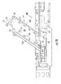
- FIGS. 10A and 10Billustrate a portion of another fiber optic cable assembly 102 that may be employed to provide furcation of the fiber optic cable 22 into one or more furcated legs 28 .
- the fiber optic cable assembly 102comprises a furcation body 104 .
- the furcation body 104can be mounted to any suitable mounting surface.
- the furcation body 104may also contain anti-rotation and attachment features, as will be described below.
- the furcation body 103receives a fiber optic cable 22 on a first end 106 of the furcation body 104 along a longitudinal axis A 10 of the furcation body 104 .
- An end cap 105is attached to the furcation body 104 , but other structures are possible.
- end cap 105snap-fits into furcation body 104 to secure the same to the furcation body 104 .
- a one-piece molded furcation body 104 without a separate end cap 105is also possible.
- the end cap or end portionmay be flexible for providing strain relief such as a boot.
- the fiber optic cable 22extends into a passage 108 extending through the furcation body 104 from the first end 106 of the furcation body 104 to a second end 110 of the furcation body 104 .
- One or more furcated legs 28extend through the second end 110 of the furcation body 104 .
- the furcation body 104has a generally cylindrically-shaped body which contains a beveled surface 112 at the first end 106 .
- An attachment feature 114is provided to attach the furcation body 103 to the mounting surface 30 that also includes an anti-rotation feature. As depicted, the attachment feature 114 is integrated into a substantially planar surface 118 of the furcation body 104 . As best shown in FIG. 10B , the attachment feature 114 is provided in the form of one or more T-shaped push latch mechanisms 120 A, 120 B (“push latches 120 A, 120 B”) attached to the furcation body 104 .
- the push latches 120 A, 120 Bare include attachment platforms 122 A, 122 B each having two substantially planar surfaces 123 A, 123 B to provide an integrated anti-rotation feature in the furcation body 104 located contiguous with the attachment feature 114 .
- the attachment platforms 122 A, 122 Bare attached to the substantially planar surface 118 . Respectively, each substantially planar surface 123 A, 123 B of the attachment platforms 122 A, 122 B is attached to outer support rails 124 A, 124 B extending generally orthogonally to the attachment platform 122 A, 122 B.
- the outer support rails 124 A, 124 Bare adapted to engage with the furcation body 104 to support and securably hold the the furcation body 104 .
- Latches 126 A, 126 Bare integratedly formed into same mold piece as the outer support rails 124 A, 124 B, respectively, and extend from the attachment platforms 122 A, 122 B such that they are adapted to be inserted into apertures, thereby securing the cable assembly to the mounting surface.
- the latches 126 A, 126 Bare biased forward and contain shoulder structures 128 A, 128 B that flex inward to be inserted into the apertures to attach the latches 126 A, 126 B and thus the furcation body 103 onto the mounting surface.
- the substantially planar surfaces 123 A, 123 Babut with the mounting surface to provide an anti-rotation feature for the cable assembly.
- the latches 126 A, 126 Bare biased downward such that the shoulder structures 128 A, 128 B cannot be pulled from the apertures unless the latches 126 A, 126 B are compressed inward so that the shoulder structures 128 A, 128 B can pass through the apertures to release the furcation body 103 from the mounting surface 30 .
- FIG. 11illustrates another embodiment of a fiber optic cable assembly 130 that may be employed to secure a furcation body to a suitable fiber optic shelf assembly.
- the fiber optic cable assembly 130includes a furcation body 131 having an end cap 133 attached thereto.
- a latching finger 135 disposed in the furcation body 132protrudes and interlocks with a latch orifice 137 disposed in the end cap 133 to secure the end cap 133 to the furcation body 132 .
- a one-piece molded furcation body 132 without a separate end cap 133is also possible.
- the furcation body 132has a first end 134 for receiving a fiber optic cable 22 along a longitudinal axis A 11 of the furcation body 132 .
- a fiber optic cableis furcated inside a passage 136 disposed within the furcation body 132 between the first end 134 and a second end 138 of the furcation body 132 . Once the fiber optic cable is furcated, one or more furcated legs 28 extend from the second end 138 to be connected to fiber optic components.
- the furcation body 132has a substantially planar surface 126 disposed on its bottom wherein a plurality of support members 144 are attached.
- the furcation body 132is integrally molded with support members 144 that support the furcation body 132 .
- the support members 144are also integrally formed with the attachment feature to mount and secure the furcation body 131 .
- the attachment feature 146is comprised of an integrally molded clip 148 .
- the integrally molded clip 148has a top substantially planar surface 150 to which the support members 144 are integrally molded.
- the top substantially planar surface 150 of the integrally molded clip 148is aligned along the longitudinal axis A 11 of the furcation body 131 such that the entire furcation body 131 is supported.
- the integrated molded clip 148also includes a plurality of substantially planar surfaces 149 to provide an anti-rotation feature in the furcation body 131 .
- the substantially planar surfaces 149are disposed on a bottom portion of the furcation body 131 and are configured to abut with a mounting surface when the furcation body 132 is mounted to a mounting surface.
- the integrally molded clip 148contains latch mechanisms in the form of two attachment latches 152 A, 152 B, wherein one attachment latch 152 A is disposed on a first end 154 of the integrally molded clip 148 and the second attachment latch 152 B is disposed on a second end 156 of the integrally molded clip 148 .
- the attachment latches 152 A, 152 Bare configured to engage suitable apertures in the mounting surface 30 using a compressible fit.
- the integrally molded clip 148contains a U-shaped compressible member 158 that attaches the attachment latch 152 A to the integrally molded clip 148 .
- attachment latch 152 Awhen the attachment latch 152 A is placed in an aperture, a force can be asserted on the integrally molded clip 148 towards the first end 154 such that the attachment latch 152 A will move forward in the aperture such that attachment latch 152 B can be placed in another aperture.
- the compression energy contained in the compressible member 158will exert a forward-biased force between the attachment latch 152 A and an aperture such that the integrally molded clip 148 will be secured.
- the substantially planar surfaces 149When secured, the substantially planar surfaces 149 will abut with a mounting surface to provide an anti-rotation feature.
- FIGS. 12A-12Dillustrate another embodiment of a fiber optic cable assembly 160 having an anti-rotation feature for securing the furcation body to a suitable fiber optic shelf assembly.
- FIG. 12Ais a perspective view of the fiber optic cable assembly 160 with a two-piece molded furcation body 162 , but other structures are possible.
- the furcation body 162includes an end cap 165 attached thereto.
- a latching finger 167 disposed in the furcation body 164protrudes and interlocks with a latch orifice 169 disposed in the end cap 165 to secure the end cap 165 to the furcation body 164 .
- a one-piece molded furcation body 164 without a separate end cap 165is also possible.
- the furcation body 164has a first end 166 for receiving a fiber optic cable (not shown) along a longitudinal axis A 12 of the furcation body 164 .
- the fiber optic cableis received in a passage 168 disposed within the furcation body 164 between the first end 166 and a second end 170 of the furcation body 164 .
- the fiber optic cableis furcated into a plurality of furcated legs (not shown) that extend out of the second end 170 of the furcation body 164 to attach to fiber optic components.
- the attachment featureis an integral portion of the furcation body 164 .
- the furcation body 164includes a plurality of attachment platform members 174 each having a substantially planar surface 177 to provide an anti-rotation feature (see also FIG. 12D ).
- the furcation body 164also includes keyhole members 176 attached via attachment platform supports 175 (see FIGS. 12B and 12C ).
- the furcation body 162 and the attachment platform members 174are mounted to a mounting surface when the keyhole members 176 are inserted into apertures. In this manner, the substantially planar surfaces 177 abut and rest flat against a mounting surface to provide an anti-rotation feature.
- the keyhole members 176are shown as being disposed along the longitudinal axis A 12 below the surface of the furcation body 164 and the attachment platform members 174 .
- the substantially planar surfaces 177 of the attachment platform members 174will abut with and rest against the mounting surface.
- the keyhole membersmay be included on a clip that has a side with a living hinge that closes about the furcation body for securing the same within the clip.
- FIG. 13illustrates the fiber optic cable assemblies 160 of FIGS. 12A-12D installed on a mounting surface 180 .
- the mounting surface 180may be disposed in any suitable fiber optic shelf assembly.
- the furcation body 162receives a fiber optic cable 182 through the first end 166 of the furcation body 164 .
- the fiber optic cable 182is furcated inside the passage 168 of the furcation body 164 extending therethrough to the second end 170 .
- a plurality of furcated legs 184extend through the second end 170 as illustrated.
- the mounting surface 180comprises a series of keyholes 186 for allowing the fiber optic cable assembly 160 to be attached to the mounting surface 180 .
- the keyhole members 176are inserted into wide portions 188 of the keyholes 186 that will allow the geometry of the keyhole members 176 to pass therethrough.
- the furcation body 162 and its keyhole members 176are pushed or pulled as indicated by the arrows 190 in FIG. 13 such that the attachment platform support 175 is inserted into narrow portions 192 of the keyholes 186 .
- the substantially planar surfaces 177abut with the mounting surface 180 to provide an anti-rotation feature for the fiber optic cable assembly 160 .
- the keyhole members 176cannot pass through the narrow portions 192 of the keyholes 186 such that the furcation body 162 is locked into place on the mounting surface 180 .
- the front locking mechanism 194comprises a T-shaped appendage 196 extending out of the second end 170 of the furcation body 164 .
- the appendage 196contains a pin 198 that is located in substantially the same plane as the attachment platform support 175 . Thus, when the pin 198 is inserted into a pin aperture 199 , as illustrated in FIG.
- the furcation body 162is prevented from moving laterally such that the furcation body 162 cannot accidentally be pushed forward opposite the direction of the arrows 190 such that the keyhole members 176 may be released from the keyholes 186 for an accidental removal or detachment from the mounting surface 180 .
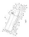
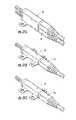
- FIGS. 14A and 14Billustrate another alternative fiber optic cable assembly 200 that may be employed for securing a furcation body that includes an anti-rotation feature.
- the fiber optic cable assembly 200includes a furcation body 202 that is comprised of a furcation body 204 .
- a fiber optic cable 206is received in a first end 208 of the furcation body 204 and extends through a passage 210 extending through the furcation body 204 to a second end 212 of the furcation body 204 along a longitudinal axis A 13 of the furcation body 204 .
- the fiber optic cable 206is furcated inside the passage 210 disposed in the furcation body 204 and furcated into a plurality of furcated legs 214 that extend from the second end 212 .
- the furcation body 202 in this embodimentis not designed to be placed against a mounting surface to secure the furcation body 202 .
- an attachment feature 216is provided in the form of a clip 218 . As shown, one or more clips 218 are placed around the furcation body 204 to secure it. The attachment feature 216 is then secured to a mounting surface to secure the furcation body 202 .
- the clip 218 of the attachment feature 216 in FIGS. 14A and 14Bcompletely surrounds the furcation body 202 such that the furcation body 202 does not touch the mounting surface.
- the clip 218is comprised of an attachment housing 222 .
- the attachment housing 222is formed from an elongated rectangular shaped piece of material that is banner formed in a substantially rectangular shape with first and second ends 224 , 226 coming together onto themselves.
- the attachment housing 222contains a substantially planar surface 223 that is configured to abut with a mounting surface when the attachment housing 222 secures the furcation body 202 to a mounting surface to provide an anti-rotation feature.
- a series of protrusions or ridges 225are disposed on the attachment housing 222 on the first end 224 .
- a locking structure 230is disposed on the second end 226 of the attachment housing 222 such that it is configured to lock the first end 224 onto the second end 226 to form the attachment housing 222 .
- the attachment housing 222After being installed around the furcation body 204 as illustrated in FIG. 14A , the attachment housing 222 also contains a button structure 232 disposed within an inner wall 234 of the attachment housing 222 that is designed to couple with a button receiver 236 disposed within the furcation body 204 .
- the furcation body 204contains a notched portion 238 that contains a series of button receivers 236 around its outer surface such that the attachment housing 222 can be rotated in a number of directions around the furcation body 202 to secure the furcation body 202 to differently-oriented mounting surfaces as desired.
- the notched portion 238has a width W 1 that is about the same width as the width W 2 of the attachment housing 222 such that the attachment housing 222 sits inside the notched portion 238 to provide a secure fit between the attachment housing 222 and the furcation body 204 when attached.
- an integrated plunger 240is provided in the attachment housing 222 .
- the integrated plunger 240is disposed within a plunger orifice 226 disposed in the attachment housing 222 .
- the integrated plunger 240contains a plunger support 244 that has an outer diameter larger than the plunger orifice 226 such that the plunger support 244 rests inside the attachment housing 222 .
- a plunger head 246is coupled to a plunger flange 248 to selectively engage the plunger flange 248 to cause it to expand or retract. When the plunger head 246 is pushed down, the plunger flange 248 expands.
- the plunger flange 248contracts.
- the plunger flange 248is placed inside an aperture or orifice and a force is exerted down on the plunger head 246 to cause the plunger flange 248 to expand within the orifice or aperture.
- the plunger flange 248is secured within the aperture or orifice to secure the attachment housing 222 therein.
- the furcation body 202is held in place within the attachment housing 222 to the mounting surface.
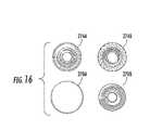
- FIGS. 15A and 15Billustrate alternate fiber optic cable assemblies 250 , 250 ′ that include an anti-rotation feature and attachment features to mount the fiber optic cable assemblies 250 , 250 ′ to mounting surfaces 252 , 252 ′.
- the fiber optic cable assemblies 250 , 250 ′include fiber optic cable 22 received in first ends 254 , 254 ′ of furcation bodies 256 , 256 ′.
- the fiber optic cable 22is received along longitudinal axes A 14 , A 15 of the furcation bodies 256 , 256 ′, respectively.
- the fiber optic cable 22is furcated inside the furcation bodies 256 , 256 ′ into a plurality of furcated legs 28 extending from second ends 258 , 258 ′ of the furcation bodies 256 , 256 ′ opposite the first ends 254 , 254 ′ of the furcation bodies 256 , 256 ′, respectively.
- the furcation bodies 256 , 256 ′each contain substantially planar surfaces 260 , 260 ′ that abut with the mounting surfaces 252 , 252 ′, respectively, to provide an anti-rotation feature when the furcation bodies 256 , 256 ′ are mounted to the mounting surfaces 252 , 252 ′.
- the furcation bodies 256 , 256 ′also contain attachment features 262 , 262 ′ to secure the furcation bodies 256 , 256 ′ to the mounting surfaces 252 , 252 ′.
- the attachment feature 262is provided in the form of button attachment features 264 A, 264 B.
- the button attachment features 264 A, 264 Beach provide a female button portion 266 A, 266 B attached to a bottom surface 268 of the furcation body 256 .
- the female button portions 266 A, 266 Bmay be provided by either of the female button portions 270 A, 270 B illustrated in FIG. 16 as examples.
- the female button portions 266 A, 266 Battach to male button portions 272 A, 272 B to secure the furcation body 256 to the mounting surface 252 .
- the male button portions 272 A, 272 Bmay be provided by either of the male button portions 274 A, 274 B illustrated in FIG. 16 as examples.
- an attachment feature 262 ′is provided in the form of button attachment features 264 A′, 264 B′.
- the button attachment features 264 A′, 264 B′each provide a male button portion 272 A′, 272 B′ attached to the substantially planar surface 260 ′ of the furcation body 256 ′.
- the male button portions 272 A′, 272 B′may be provided by either of the male button portions 274 A, 274 B illustrated in FIG. 16 as examples.
- the male button portions 272 A′, 272 B′attach to female button portions 266 A′, 266 B′ to secure the furcation body 256 ′ to the mounting surface 252 .
- the substantially planar surface 260 ′abuts with the mounting surface 252 ′ to provide an anti-rotation feature in the furcation body 256 ′.
- the female button portions 266 A, 266 Bmay be provided by either of the female button portions 270 A, 270 B illustrated in FIG. 16 as examples.
- FIG. 17illustrates an embodiment of fiber optic equipment in the form of a fiber optic shelf assembly 300 providing one explanatory furcation management structure 302 having an array of apertures for mounting furcation bodies.
- a furcation management structureis separate from but may be attached and/or provided in fiber optic equipment for mounting one or more furcation assemblies.
- the furcation management structure 302facilitates the management and routing of fiber optic cable assemblies 304 by securing one or more furcation bodies 306 thereto. Additionally, any suitable fiber optic cable assemblies 304 and/or furcation bodies 306 may be used.
- the furcation management structure 302is attached to a chassis 308 of the fiber optic shelf assembly 300 . More specifically, the furcation management structure 302 is attached to a rear portion 310 of the chassis 308 .
- One or more fiber optic cables 312 of a fiber optic cable assembly 304are typically routed to establish fiber optic connections with one or more fiber optic modules 313 provided in the fiber optic shelf assembly 300 .
- the fiber optic cable assembly 304includes furcation of the fiber optic cable 312 into one or more furcated legs 314 , which are typically connectorized and connected to fiber optic adapters 316 disposed in the rear of the fiber optic modules 313 .
- the furcation body 306 of the fiber optic cable assembly 304is secured to the furcation management structure 302 .
- the furcation management structure 302is comprised of a furcation bracket 317 comprising a mounting surface 318 containing an attachment feature in the form of a series of pre-defined apertures 320 .
- the apertures 320may be arranged like the apertures in the mounting surfaces previously described above.
- a securing device in the form of plungers 321 A, 321 Bare disposed in an attachment feature of the furcation body 306 , such as those previously described above, and secured to the apertures 320 in the furcation bracket 317 to mount the furcation body 306 to the furcation management structure 302 .
- the mounting surface 318 of the furcation bracket 317is similar to the mounting surfaces previously described above.
- the furcation bracket 317also contains a first end 319 and a second end 322 disposed on an opposite side of the first end 319 .
- the furcation bracket 317contains at least one portion that is removably attached to the chassis 308 such that additional furcation body of other fiber optic cable assemblies can be disposed underneath the furcation bracket 317 and mounted directly to the rear portion 310 of the chassis 308 to increase the density of fiber optic cable assemblies 304 that can be disposed in the fiber optic shelf assembly 300 .
- FIG. 18illustrates a close-up perspective view of the furcation management structure 302 with the furcation bracket 317 in a closed position. Only the furcation body 306 of the fiber optic cable assembly 304 is illustrated so as to not obstruct features discussed herein with regard to FIG. 18 . However, the fiber optic cable 312 and furcated legs 314 would extend from the furcation body 306 in the actual fiber optic cable assembly 304 . As illustrated, the furcation bracket 317 is hingedly mounted to the rear portion 310 via a hinge assembly 324 .
- the hinge assembly 324is comprised of a hinge 326 attached between a bottom side 328 (see FIG.
- the hinge assembly 324allows the furcation bracket 317 to be lifted on its first end 319 about the rear portion 310 for access underneath.
- the first end 319is removably attached to the rear portion 310 via an attachment feature provided in the form of an attachment platform 330 .
- the attachment platform 330extends from the first end 319 of the furcation bracket 317 and contains an aperture 332 (see also, FIG. 19 ).
- a securing device in the form of a plunger 334is disposed in the aperture 332 and is configured to cooperatively engage with an aperture 336 disposed in a standoff platform 338 (see FIG. 19 ) to be secured to the rear portion 310 in a closed position.
- the furcation bracket 317When closed, as illustrated in FIG. 18 , the furcation bracket 317 forms an internal cavity 340 underneath the mounting surface 318 disposed between the first end 319 , the second end 322 , and curved surfaces 342 A, 342 B disposed orthogonally therebetween.
- the curved surfaces 342 A, 342 Bprovide a waterfall feature for the fiber optic cables 312 and the furcated legs 314 to lay over or against to prevent or reduce bending or kinking when installed on the furcation bracket 317 .
- the internal cavity 340provides for additional furcation bodies 344 (see also, FIG. 19 ) to be attached directly to the rear portion 310 underneath the furcation bracket 317 to allow for an increased density of fiber optic cable assemblies to be included in the fiber optic shelf assembly 300 .
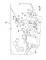
- FIGS. 19 and 20illustrate the furcation bracket 317 in an open position.
- the hinge assembly 324contains an internal spring (not shown) to bias the furcation bracket 317 in the open position when not secured to the standoff platform 338 .
- the rear portion 310has a series of apertures 348 to receive securing devices for attachment features of the furcation bodies 344 disposed beneath the furcation bracket 317 , which may include the configurations previously provided and described in FIGS. 1-16 .
- one or more standoffs 350may be disposed on the bottom side 328 of the furcation bracket 317 that rest against the rear portion 310 to provide additional support when the furcation bracket 317 is closed.
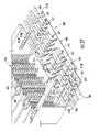
- FIGS. 21-27illustrate various additional embodiments of furcation management structures and/or assemblies that may be employed to manage furcation bodies of fiber optic cable assemblies.
- one or more furcation trays 352 disposed in fiber optic equipment in the form of a fiber optic shelf assembly 354are provided.
- the furcation management structuresmay include one or more furcation platforms 356 that mount to the fiber optic equipment, thereby making it possible to retrofit into existing equipment.
- Both the furcation trays 352 and furcation platforms 356are disposed on a bottom mounting surface 359 in a rear portion 357 of the fiber optic shelf assembly 354 to support one or more furcation bodies of respective fiber optic cable assemblies 357 .
- These fiber optic cable assemblies 357include furcation bodies 358 receiving a fiber optic cable 360 and providing one or more furcated legs 362 .
- the furcated legs 362may be connectorized with fiber optic connectors and connected to fiber optic adapters 364 disposed in one or more fiber optic modules 366 in the fiber optic shelf assembly 354 .
- Furcation management structuressuch as furcation trays 352 and furcation platforms 356 facilitate providing higher density of fiber optic cable assemblies 357 in the fiber optic shelf assembly 354 along with improved organization.
- FIG. 22illustrates a top view of a furcation tray 352 that is disposed in the fiber optic shelf assembly 354 in FIG. 21 in more detail.
- the furcation tray 352is comprised of a mounting surface 361 .
- the furcation tray 352may be constructed out of any suitable material such as sheet metal, aluminum, plastic, and the like.
- the furcation tray 352may contain a series of indentures 365 and protrusions 367 on outer edges of the furcation tray 352 that are configured to cooperate with opposing protrusions and indentures disposed on the mounting surface 359 of the fiber optic shelf assembly 354 .
- a series of pre-defined apertures 355may also be provided in the mounting surface 359 to receive fasteners (not shown) for securing the furcation tray 352 to the fiber optic shelf assembly 354 .
- the mounting surface 361 of the furcation tray 352contains a series of pre-defined apertures 368 that receive securing devices 371 (see FIG. 24 ) disposed in an attachment feature 369 of the furcation body 358 .
- the apertures 368are located in offsetting axes (e.g., A 16 , A 17 ) such that the fiber optic cable 360 of one furcation body 358 disposed in a first row (e.g., R 1 ) is disposed in between two adjacent furcation bodies 358 in a second row (e.g, R 2 ).
- the furcation tray 352includes eight (8) furcation bodies 358 facing the same direction.
- the furcation tray 352includes eight (8) additional furcation bodies 358 in rows R 3 and R 4 facing an opposite direction of the furcation bodies 358 in rows R 1 and R 2 to provide for a total of sixteen (16) furcation bodies 358 .
- the furcated legs 362are all routed to a center section 370 of the furcation tray 352 for routing to the fiber optic modules 366 .
- one or more furcation platforms 356may also be disposed in the fiber optic shelf assembly 354 to provide additional furcation management.
- One furcation platform 356is illustrated as being provided in FIG. 21 ; however, additional furcation platforms 356 can be disposed above the furcation tray 352 in a stacked arrangement in the Y-axis (“Y”) (see FIG. 25 ), as desired.
- the furcation platform 356contains a mounting surface 374 similar to the mounting surface 361 of the furcation tray 352 .
- One or more indentures 376are provided in corners 378 of the furcation platform 356 to mount the furcation platform 356 above the furcation tray 352 .
- the furcation platform 356is mounted to standoffs 380 ( FIG. 21 ) inserted into the indentures 376 .
- an additional aperture 379is provided for mounting the furcation platform 356 as an appendage from the furcation tray 352 .
- the furcation platform 356is mounted above the mounting surface 359 of the fiber optic shelf assembly 354 similar to the furcation bracket 317 to provide additional mounting space for fiber optic cable assemblies.
- the mounting surface 374 of the furcation platform 356contains a series of pre-defined apertures 382 that receive securing devices disposed in attachment features of the furcation bodies 358 .
- the apertures 382are located in offsetting axes (e.g., A 18 , A 19 ) such that the fiber optic cable 360 of one furcation body 358 disposed in a first row (e.g., R 5 ) is disposed in between two adjacent furcation bodies 358 in a second row (e.g, R 6 ).
- the furcation tray 352includes eight (8) furcation bodies 358 facing the same direction.
- FIG. 24illustrates a furcation platform 356 provided as an appendage to a furcation tray 352 and a fiber optic shelf assembly 354 to provide additional options for providing additional furcation management.
- the furcation platform 356 and furcation bodies 358 secured thereinare the same as illustrated in FIG. 22 .
- the furcation platform 356is secured to a rear side 389 of the fiber optic shelf assembly 354 via the additional aperture 379 , which receives a securing device 390 disposed in the furcation tray 352 to secure the furcation platform 356 to the fiber optic shelf assembly 354 .
- FIG. 25illustrates a side view of the fiber optic shelf assembly 354 of FIG. 21 , and illustrates a furcation tray 392 disposed on a top shelf 394 of the fiber optic shelf assembly 354 to provide additional furcation management.
- the top shelf 394provides another mounting surface to mount additional furcation trays 392 and/or furcation platforms (not included in FIG. 25 ), if desired.
- the furcation tray 392may be provided that contains the same features as the furcation tray 352 illustrated in FIG. 22 and thus will not be repeated here.
- FIG. 25illustrates more detail regarding the standoff 380 to support a furcation platform 356 disposed above the furcation tray 352 .
- the standoff 380is disposed in a standoff orifice 402 disposed in the furcation tray 352 and into the mounting surface 359 .
- FIG. 26illustrates the fiber optic shelf assembly 354 as well, but with an intermediate shelf 396 provided.
- the intermediate shelf 396can support an intermediate furcation tray 398 for providing furcation management.
- the furcation tray 392may be provided that contains the same features as the furcation tray 352 illustrated in FIG. 22 and thus will not be repeated here.
- FIG. 27illustrates furcation management structures such as furcation trays, platforms or the like may be slidable with respect to the fiber optic shelf assembly 354 to be translated in and out from the fiber optic shelf assembly 354 .
- Translation of a furcation trayallows access to any fiber optic cable assemblies, including their furcation bodies, disposed in the furcation tray for access, routing, configuration, reconfiguration, etc.
- the intermediate furcation tray 398is translated out from the fiber optic shelf assembly 354 .
- the intermediate furcation tray 398is disposed between shelves provided in the form of shelf supports 410 A, 410 B on each side of the rear side 389 of the fiber optic shelf assembly 354 .
- the shelf supports 410 A, 410 Binclude a guide system in the form of rail guides 412 A, 412 B.
- the rail guides 412 A, 412 Breceive rails 413 A, 413 B disposed on each side of a rear side 414 and a front side 416 of the intermediate furcation tray 398 . In this manner, the intermediate furcation tray 398 can be pulled and pushed about on the rails 413 A, 413 B to translate in and out of the fiber optic shelf assembly 354 about the rails guides 412 A, 412 B.
- the rail guides 412 A, 412 Bis provided in FIG. 27 as a friction fit guide system; however, a bearing guide system, or any other type of guide system may be employed.
- FIGS. 28-30depict a various views of another alternate furcation management structure mounted in a fiber optic shelf assembly.
- fiber optic shelf assembly 354includes two furcation platforms 356 (i.e., a plurality of furcation management structures) mounted on opposing sides of the fiber optic shelf assembly for securing and managing respective fiber optic cable assemblies 357 that are routed therein.
- furcation platform 356has multiple levels 356 a and 356 b for securing the furcation bodies. Moreover, the multiple levels are located on non-parallel planes, but it is possible to locate the multiple levels on generally parallel planes.
- furcation platforms 356are mounted to the sides of fiber optic shelf assembly 354 using a suitable fasenter 393 such as screws, but they mount to the rear, top, or other location. Of course, other fasteners are possible. Other variations of furcation platforms and furcation trays are possible according to the concepts disclosed herein.
- FIGS. 31A-31Dshow perspective views of other clips for securing furcation bodies of fiber optic cable assemblies.
- FIG. 31Adepicts clip 50 for securing a plurality of furcation bodies 26 of cable assemblies in a vertical arrangement; instead of a horizontal arrangement. This arrangement is most advantageous when the furcation bodies are smaller, but may be used with any size furcation body.
- other variations of the clipmay be configured to secure any suitable number of rows and/or columns of furcation bodies secured by the clip.
- Other variations of clipscan modify the number and/or location of attachment platforms on the clips as shown in FIGS. 31B and 31C .
- the clip of FIG. 31Bhas four attachment platforms with respective apertures that receive plungers for securing the same and the clip of FIG. 31C has three attachment platforms.
- Other clip variationsinclude having attachment platforms with apertures on upper and lower surfaces, thereby creating a vertical stacking arrangement as shown in FIG. 31D .
- the furcation bodiesare not shown in the view so that the stacking arrangement is visible.
- one or more plungers 60are used to secure a first clip to as second clip as shown to increase the fiber optic cable assembly density of the structure or assembly.
Landscapes
- Physics & Mathematics (AREA)
- General Physics & Mathematics (AREA)
- Optics & Photonics (AREA)
- Light Guides In General And Applications Therefor (AREA)
- Installation Of Indoor Wiring (AREA)
Abstract
Description
Claims (3)
Priority Applications (12)
| Application Number | Priority Date | Filing Date | Title |
|---|---|---|---|
| US12/417,325US8301004B2 (en) | 2008-08-29 | 2009-04-02 | Fiber optic cable assemblies employing a furcation body having anti-rotation feature |
| US12/487,929US8285104B2 (en) | 2008-08-29 | 2009-06-19 | Clip for securing a fiber optic cable assembly and associated assemblies |
| EP09789077AEP2321687A2 (en) | 2008-08-29 | 2009-08-06 | Fiber optic cable assemblies employing a furcation body having anti-rotation feature |
| EP09789068.5AEP2324384B1 (en) | 2008-08-29 | 2009-08-06 | Clip for securing a fiber optic cable assembly |
| PCT/US2009/004521WO2010024844A2 (en) | 2008-08-29 | 2009-08-06 | Fiber optic cable assemblies employing a furcation body having anti-rotation feature |
| AU2009286115AAU2009286115A1 (en) | 2008-08-29 | 2009-08-06 | Fiber optic cable assemblies employing a furcation body having anti-rotation feature |
| CN200980137616.0ACN102165354B (en) | 2008-08-29 | 2009-08-06 | Clamps and associated components for securing fiber optic cable assemblies |
| PCT/US2009/004497WO2010024842A1 (en) | 2008-08-29 | 2009-08-06 | Clip for securing a fiber optic cable assembly and associated assemblies |
| AU2009286113AAU2009286113C1 (en) | 2008-08-29 | 2009-08-06 | Clip for securing a fiber optic cable assembly and associated assemblies |
| CN200980137610.3ACN102165353B (en) | 2008-08-29 | 2009-08-06 | Fiber optic cable assemblies employing a furcation body having anti-rotation feature |
| US12/751,839US8290333B2 (en) | 2008-08-29 | 2010-03-31 | Fiber optic cable assemblies with furcation bodies having features for manufacturing and methods of making the same |
| US13/612,026US8559785B2 (en) | 2008-08-29 | 2012-09-12 | Clip for a fiber optic assembly |
Applications Claiming Priority (3)
| Application Number | Priority Date | Filing Date | Title |
|---|---|---|---|
| US19053808P | 2008-08-29 | 2008-08-29 | |
| US19706808P | 2008-10-23 | 2008-10-23 | |
| US12/417,325US8301004B2 (en) | 2008-08-29 | 2009-04-02 | Fiber optic cable assemblies employing a furcation body having anti-rotation feature |
Related Child Applications (1)
| Application Number | Title | Priority Date | Filing Date |
|---|---|---|---|
| US12/487,929Continuation-In-PartUS8285104B2 (en) | 2008-08-29 | 2009-06-19 | Clip for securing a fiber optic cable assembly and associated assemblies |
Publications (2)
| Publication Number | Publication Date |
|---|---|
| US20100086267A1 US20100086267A1 (en) | 2010-04-08 |
| US8301004B2true US8301004B2 (en) | 2012-10-30 |
Family
ID=41298641
Family Applications (1)
| Application Number | Title | Priority Date | Filing Date |
|---|---|---|---|
| US12/417,325Active2030-07-19US8301004B2 (en) | 2008-08-29 | 2009-04-02 | Fiber optic cable assemblies employing a furcation body having anti-rotation feature |
Country Status (5)
| Country | Link |
|---|---|
| US (1) | US8301004B2 (en) |
| EP (1) | EP2321687A2 (en) |
| CN (1) | CN102165353B (en) |
| AU (1) | AU2009286115A1 (en) |
| WO (1) | WO2010024844A2 (en) |
Cited By (51)
| Publication number | Priority date | Publication date | Assignee | Title |
|---|---|---|---|---|
| US8879881B2 (en) | 2010-04-30 | 2014-11-04 | Corning Cable Systems Llc | Rotatable routing guide and assembly |
| US8913866B2 (en) | 2010-03-26 | 2014-12-16 | Corning Cable Systems Llc | Movable adapter panel |
| US8953924B2 (en) | 2011-09-02 | 2015-02-10 | Corning Cable Systems Llc | Removable strain relief brackets for securing fiber optic cables and/or optical fibers to fiber optic equipment, and related assemblies and methods |
| US8965168B2 (en) | 2010-04-30 | 2015-02-24 | Corning Cable Systems Llc | Fiber management devices for fiber optic housings, and related components and methods |
| US8985862B2 (en) | 2013-02-28 | 2015-03-24 | Corning Cable Systems Llc | High-density multi-fiber adapter housings |
| US8989547B2 (en) | 2011-06-30 | 2015-03-24 | Corning Cable Systems Llc | Fiber optic equipment assemblies employing non-U-width-sized housings and related methods |
| US8992099B2 (en) | 2010-02-04 | 2015-03-31 | Corning Cable Systems Llc | Optical interface cards, assemblies, and related methods, suited for installation and use in antenna system equipment |
| US8995812B2 (en) | 2012-10-26 | 2015-03-31 | Ccs Technology, Inc. | Fiber optic management unit and fiber optic distribution device |
| US9008485B2 (en) | 2011-05-09 | 2015-04-14 | Corning Cable Systems Llc | Attachment mechanisms employed to attach a rear housing section to a fiber optic housing, and related assemblies and methods |
| US9020320B2 (en) | 2008-08-29 | 2015-04-28 | Corning Cable Systems Llc | High density and bandwidth fiber optic apparatuses and related equipment and methods |
| US9022814B2 (en) | 2010-04-16 | 2015-05-05 | Ccs Technology, Inc. | Sealing and strain relief device for data cables |
| US9042702B2 (en) | 2012-09-18 | 2015-05-26 | Corning Cable Systems Llc | Platforms and systems for fiber optic cable attachment |
| US9038832B2 (en) | 2011-11-30 | 2015-05-26 | Corning Cable Systems Llc | Adapter panel support assembly |
| US9075217B2 (en) | 2010-04-30 | 2015-07-07 | Corning Cable Systems Llc | Apparatuses and related components and methods for expanding capacity of fiber optic housings |
| US9140872B2 (en) | 2013-09-17 | 2015-09-22 | Panduit Corp. | Hydra cable assembly and components thereof |
| US9213161B2 (en) | 2010-11-05 | 2015-12-15 | Corning Cable Systems Llc | Fiber body holder and strain relief device |
| US9250409B2 (en) | 2012-07-02 | 2016-02-02 | Corning Cable Systems Llc | Fiber-optic-module trays and drawers for fiber-optic equipment |
| US9279951B2 (en) | 2010-10-27 | 2016-03-08 | Corning Cable Systems Llc | Fiber optic module for limited space applications having a partially sealed module sub-assembly |
| US9519118B2 (en) | 2010-04-30 | 2016-12-13 | Corning Optical Communications LLC | Removable fiber management sections for fiber optic housings, and related components and methods |
| US9645317B2 (en) | 2011-02-02 | 2017-05-09 | Corning Optical Communications LLC | Optical backplane extension modules, and related assemblies suitable for establishing optical connections to information processing modules disposed in equipment racks |
| US9690065B2 (en) | 2014-09-12 | 2017-06-27 | Panduit Corp. | High density fiber enclosure and method |
| US9893813B2 (en) | 2009-03-05 | 2018-02-13 | Commscope Technologies Llc | Methods, systems, and devices for integrating wireless technology into a fiber optic network |
| USRE46780E1 (en) | 2009-06-08 | 2018-04-10 | Commscope, Inc. Of North Carolina | High density patching system for cable and optical fiber |
| US10094996B2 (en) | 2008-08-29 | 2018-10-09 | Corning Optical Communications, Llc | Independently translatable modules and fiber optic equipment trays in fiber optic equipment |
| US10215944B2 (en) | 2016-06-30 | 2019-02-26 | Panduit Corp. | Modular fiber optic tray |
| US10359577B2 (en) | 2017-06-28 | 2019-07-23 | Corning Research & Development Corporation | Multiports and optical connectors with rotationally discrete locking and keying features |
| US10379298B2 (en) | 2017-06-28 | 2019-08-13 | Corning Research & Development Corporation | Fiber optic connectors and multiport assemblies including retention features |
| US10495825B2 (en) | 2010-08-02 | 2019-12-03 | Commscope Technologies Llc | Architecture for a fiber optic network |
| US10641967B1 (en) | 2018-11-16 | 2020-05-05 | Corning Research & Development Corporation | Multiport assemblies including a modular adapter support array |
| US10768382B2 (en) | 2018-11-29 | 2020-09-08 | Corning Research & Development Corporation | Multiport assemblies including access apertures and a release tool |
| US11073670B2 (en) | 2016-08-12 | 2021-07-27 | Corning Optical Communications LLC | Device and method for sealing multiport splitters |
| US11187859B2 (en) | 2017-06-28 | 2021-11-30 | Corning Research & Development Corporation | Fiber optic connectors and methods of making the same |
| US11243367B2 (en) | 2018-08-03 | 2022-02-08 | Afl Telecommunications Llc | Multiple cable size fiber optic transition assemblies |
| US11294136B2 (en) | 2008-08-29 | 2022-04-05 | Corning Optical Communications LLC | High density and bandwidth fiber optic apparatuses and related equipment and methods |
| US11294133B2 (en) | 2019-07-31 | 2022-04-05 | Corning Research & Development Corporation | Fiber optic networks using multiports and cable assemblies with cable-to-connector orientation |
| US11300746B2 (en) | 2017-06-28 | 2022-04-12 | Corning Research & Development Corporation | Fiber optic port module inserts, assemblies and methods of making the same |
| US11487073B2 (en) | 2019-09-30 | 2022-11-01 | Corning Research & Development Corporation | Cable input devices having an integrated locking feature and assemblies using the cable input devices |
| US11536921B2 (en) | 2020-02-11 | 2022-12-27 | Corning Research & Development Corporation | Fiber optic terminals having one or more loopback assemblies |
| US11604320B2 (en) | 2020-09-30 | 2023-03-14 | Corning Research & Development Corporation | Connector assemblies for telecommunication enclosures |
| US11650388B2 (en) | 2019-11-14 | 2023-05-16 | Corning Research & Development Corporation | Fiber optic networks having a self-supporting optical terminal and methods of installing the optical terminal |
| US11668890B2 (en) | 2017-06-28 | 2023-06-06 | Corning Research & Development Corporation | Multiports and other devices having optical connection ports with securing features and methods of making the same |
| US11686913B2 (en) | 2020-11-30 | 2023-06-27 | Corning Research & Development Corporation | Fiber optic cable assemblies and connector assemblies having a crimp ring and crimp body and methods of fabricating the same |
| US11880076B2 (en) | 2020-11-30 | 2024-01-23 | Corning Research & Development Corporation | Fiber optic adapter assemblies including a conversion housing and a release housing |
| US11886010B2 (en) | 2019-10-07 | 2024-01-30 | Corning Research & Development Corporation | Fiber optic terminals and fiber optic networks having variable ratio couplers |
| US11927810B2 (en) | 2020-11-30 | 2024-03-12 | Corning Research & Development Corporation | Fiber optic adapter assemblies including a conversion housing and a release member |
| US11947167B2 (en) | 2021-05-26 | 2024-04-02 | Corning Research & Development Corporation | Fiber optic terminals and tools and methods for adjusting a split ratio of a fiber optic terminal |
| US11994722B2 (en) | 2020-11-30 | 2024-05-28 | Corning Research & Development Corporation | Fiber optic adapter assemblies including an adapter housing and a locking housing |
| US12019279B2 (en) | 2019-05-31 | 2024-06-25 | Corning Research & Development Corporation | Multiports and other devices having optical connection ports with sliding actuators and methods of making the same |
| US12044894B2 (en) | 2018-12-28 | 2024-07-23 | Corning Research & Development Corporation | Multiport assemblies including mounting features or dust plugs |
| US12271040B2 (en) | 2017-06-28 | 2025-04-08 | Corning Research & Development Corporation | Fiber optic extender ports, assemblies and methods of making the same |
| US12372727B2 (en) | 2020-10-30 | 2025-07-29 | Corning Research & Development Corporation | Female fiber optic connectors having a rocker latch arm and methods of making the same |
Families Citing this family (15)
| Publication number | Priority date | Publication date | Assignee | Title |
|---|---|---|---|---|
| JP2009210669A (en)* | 2008-03-03 | 2009-09-17 | Furukawa Electric Co Ltd:The | Connector unit |
| US8290333B2 (en)* | 2008-08-29 | 2012-10-16 | Corning Cable Systems Llc | Fiber optic cable assemblies with furcation bodies having features for manufacturing and methods of making the same |
| EP2221932B1 (en) | 2009-02-24 | 2011-11-16 | CCS Technology Inc. | Holding device for a cable or an assembly for use with a cable |
| US8699838B2 (en) | 2009-05-14 | 2014-04-15 | Ccs Technology, Inc. | Fiber optic furcation module |
| US7945136B2 (en)* | 2009-06-19 | 2011-05-17 | Corning Cable Systems Llc | Mounting of fiber optic cable assemblies within fiber optic shelf assemblies |
| US8712206B2 (en) | 2009-06-19 | 2014-04-29 | Corning Cable Systems Llc | High-density fiber optic modules and module housings and related equipment |
| US8714368B2 (en)* | 2009-09-09 | 2014-05-06 | Adc Telecommunications, Inc. | Pass-through trough |
| US8538227B2 (en)* | 2010-05-14 | 2013-09-17 | Corning Cable Systems Llc | Furcation management structures |
| CN102480860A (en)* | 2010-11-25 | 2012-05-30 | 鸿富锦精密工业(深圳)有限公司 | Electronic device |
| US8958673B2 (en) | 2011-05-27 | 2015-02-17 | Corning Cable Systems Llc | Molded fiber optic cable furcation assemblies, and related fiber optic components, assemblies, and methods |
| US8559784B2 (en)* | 2011-10-26 | 2013-10-15 | All Systems Broadband, Inc. | Modular assembly for supporting fiber optic splices |
| US8731364B2 (en) | 2011-11-21 | 2014-05-20 | Ortronics, Inc. | Breakout assemblies and associated mounting members for fiber optic applications |
| EP2674797B1 (en)* | 2012-06-13 | 2017-08-23 | TE Connectivity Nederland B.V. | Cable fixture assembly for fastening at least one cable at a cable carrier as well as a splitter comprising such cable fixture assembly |
| US20140247541A1 (en)* | 2013-02-26 | 2014-09-04 | Realm Communications Group, Inc. | Telecom cabinet dual tray slider |
| US20160216471A1 (en)* | 2015-01-27 | 2016-07-28 | Corning Optical Communications LLC | Fiber optic assemblies with a fiber optic cable movable between cable openings |
Citations (26)
| Publication number | Priority date | Publication date | Assignee | Title |
|---|---|---|---|---|
| EP0490698A1 (en) | 1990-12-13 | 1992-06-17 | The Furukawa Electric Co., Ltd. | Method of stacking ferrules of a stacked-type optical connector and a stacked-type optical connector |
| EP0544004A1 (en) | 1991-05-29 | 1993-06-02 | The Furukawa Electric Co., Ltd. | Furcating part of covered multi-core optical fiber |
| US5689607A (en) | 1994-12-08 | 1997-11-18 | Alcatel Cable Interface | Device for holding at least one optical fiber cable, and a splice box making use of the device |
| US5956439A (en) | 1997-09-22 | 1999-09-21 | Lucent Technologies Inc. | Optical switching apparatus for use in the construction mode testing of fibers in an optical cable |
| US6061492A (en) | 1997-04-09 | 2000-05-09 | Siecor Corporation | Apparatus and method for interconnecting fiber cables |
| EP1041417A2 (en) | 1999-04-01 | 2000-10-04 | Siecor Operations, LLC | Fiber optic connector sleeve |
| US6278831B1 (en) | 1999-01-08 | 2001-08-21 | Priority Electronics Inc. | Fiber optic cable assembly |
| US6434316B1 (en) | 2000-06-23 | 2002-08-13 | Molex Incorporated | Fiber optic connector |
| US20020150372A1 (en) | 2001-02-12 | 2002-10-17 | Fiber Optic Network Solutions Corp. | Optical fiber enclosure system |
| US20030174996A1 (en)* | 2002-03-15 | 2003-09-18 | Fiber Optic Network Solutions, Inc. | Optical fiber enclosure system using integrated optical connector and coupler assembly |
| US6640042B2 (en)* | 1998-09-01 | 2003-10-28 | Fujitsu Limited | Optical fiber holder |
| US20040013390A1 (en) | 2002-07-22 | 2004-01-22 | Matthew Kim | Fiber management drawer and sliding slack limiter |
| US6687450B1 (en) | 2000-05-15 | 2004-02-03 | Tyco Electronics Raychem Nv | Break-out device |
| US20040208459A1 (en) | 2003-01-21 | 2004-10-21 | Toshio Mizue | Optical module |
| US20050111809A1 (en) | 2003-11-26 | 2005-05-26 | Giraud William J. | Connector housing having a sliding tray with a hingeable portion |
| US20070031099A1 (en) | 2005-08-02 | 2007-02-08 | Herzog Daniel J | Cable management panel with rear entry |
| US7200316B2 (en) | 2003-11-26 | 2007-04-03 | Corning Cable Systems Llc | Connector housing for a communication network |
| US7234878B2 (en)* | 2003-08-11 | 2007-06-26 | 3M Innovative Properties Company | Optical fiber connecting device |
| US7310471B2 (en) | 2005-08-25 | 2007-12-18 | Adc Telecommunications, Inc. | Stackable splice chip device |
| US7330629B2 (en)* | 2005-08-31 | 2008-02-12 | Corning Cable Systems Llc | Fiber optic universal bracket apparatus and methods |
| WO2008063054A2 (en) | 2006-11-23 | 2008-05-29 | Optical Telecommunications Zederik Assembly B.V. | Holder for optical fibres or other conductors |
| US20080131068A1 (en) | 2004-03-08 | 2008-06-05 | Adc Telecommunications, Inc. | Fiber Access Terminal |
| US7471867B2 (en) | 2007-05-15 | 2008-12-30 | Commscope Inc. Of North Carolina | Fiber optic splice and distribution enclosure |
| US20090060440A1 (en) | 2007-08-27 | 2009-03-05 | William Wright | Optical fiber fanout devices and methods for forming the same |
| US7603020B1 (en) | 2008-05-27 | 2009-10-13 | Emerson Network Power, Energy Systems, North America, Inc. | Cable clamp with integrated trace and bond capability |
| US7822310B2 (en) | 2007-02-28 | 2010-10-26 | Corning Cable Systems Llc | Fiber optic splice trays |
Family Cites Families (2)
| Publication number | Priority date | Publication date | Assignee | Title |
|---|---|---|---|---|
| GB8915846D0 (en) | 1989-07-11 | 1989-08-31 | Bicc Plc | Termination system for optical fibres |
| US7461981B2 (en)* | 2006-12-08 | 2008-12-09 | Corning Cable Systems Llc | Furcation tubing and fanout furcation kit |
- 2009
- 2009-04-02USUS12/417,325patent/US8301004B2/enactiveActive
- 2009-08-06AUAU2009286115Apatent/AU2009286115A1/ennot_activeAbandoned
- 2009-08-06WOPCT/US2009/004521patent/WO2010024844A2/enactiveApplication Filing
- 2009-08-06EPEP09789077Apatent/EP2321687A2/ennot_activeWithdrawn
- 2009-08-06CNCN200980137610.3Apatent/CN102165353B/ennot_activeExpired - Fee Related
Patent Citations (27)
| Publication number | Priority date | Publication date | Assignee | Title |
|---|---|---|---|---|
| EP0490698A1 (en) | 1990-12-13 | 1992-06-17 | The Furukawa Electric Co., Ltd. | Method of stacking ferrules of a stacked-type optical connector and a stacked-type optical connector |
| EP0544004A1 (en) | 1991-05-29 | 1993-06-02 | The Furukawa Electric Co., Ltd. | Furcating part of covered multi-core optical fiber |
| US5689607A (en) | 1994-12-08 | 1997-11-18 | Alcatel Cable Interface | Device for holding at least one optical fiber cable, and a splice box making use of the device |
| US6061492A (en) | 1997-04-09 | 2000-05-09 | Siecor Corporation | Apparatus and method for interconnecting fiber cables |
| US5956439A (en) | 1997-09-22 | 1999-09-21 | Lucent Technologies Inc. | Optical switching apparatus for use in the construction mode testing of fibers in an optical cable |
| US6640042B2 (en)* | 1998-09-01 | 2003-10-28 | Fujitsu Limited | Optical fiber holder |
| US6278831B1 (en) | 1999-01-08 | 2001-08-21 | Priority Electronics Inc. | Fiber optic cable assembly |
| EP1041417A2 (en) | 1999-04-01 | 2000-10-04 | Siecor Operations, LLC | Fiber optic connector sleeve |
| US6687450B1 (en) | 2000-05-15 | 2004-02-03 | Tyco Electronics Raychem Nv | Break-out device |
| US6434316B1 (en) | 2000-06-23 | 2002-08-13 | Molex Incorporated | Fiber optic connector |
| US20020150372A1 (en) | 2001-02-12 | 2002-10-17 | Fiber Optic Network Solutions Corp. | Optical fiber enclosure system |
| US20030174996A1 (en)* | 2002-03-15 | 2003-09-18 | Fiber Optic Network Solutions, Inc. | Optical fiber enclosure system using integrated optical connector and coupler assembly |
| US20040013390A1 (en) | 2002-07-22 | 2004-01-22 | Matthew Kim | Fiber management drawer and sliding slack limiter |
| US20040208459A1 (en) | 2003-01-21 | 2004-10-21 | Toshio Mizue | Optical module |
| US7234878B2 (en)* | 2003-08-11 | 2007-06-26 | 3M Innovative Properties Company | Optical fiber connecting device |
| US7200316B2 (en) | 2003-11-26 | 2007-04-03 | Corning Cable Systems Llc | Connector housing for a communication network |
| US20050111809A1 (en) | 2003-11-26 | 2005-05-26 | Giraud William J. | Connector housing having a sliding tray with a hingeable portion |
| US20080131068A1 (en) | 2004-03-08 | 2008-06-05 | Adc Telecommunications, Inc. | Fiber Access Terminal |
| US20070031099A1 (en) | 2005-08-02 | 2007-02-08 | Herzog Daniel J | Cable management panel with rear entry |
| US7310471B2 (en) | 2005-08-25 | 2007-12-18 | Adc Telecommunications, Inc. | Stackable splice chip device |
| US7764858B2 (en) | 2005-08-25 | 2010-07-27 | Adc Telecommunications, Inc. | Stackable splice chip device |
| US7330629B2 (en)* | 2005-08-31 | 2008-02-12 | Corning Cable Systems Llc | Fiber optic universal bracket apparatus and methods |
| WO2008063054A2 (en) | 2006-11-23 | 2008-05-29 | Optical Telecommunications Zederik Assembly B.V. | Holder for optical fibres or other conductors |
| US7822310B2 (en) | 2007-02-28 | 2010-10-26 | Corning Cable Systems Llc | Fiber optic splice trays |
| US7471867B2 (en) | 2007-05-15 | 2008-12-30 | Commscope Inc. Of North Carolina | Fiber optic splice and distribution enclosure |
| US20090060440A1 (en) | 2007-08-27 | 2009-03-05 | William Wright | Optical fiber fanout devices and methods for forming the same |
| US7603020B1 (en) | 2008-05-27 | 2009-10-13 | Emerson Network Power, Energy Systems, North America, Inc. | Cable clamp with integrated trace and bond capability |
Cited By (133)
| Publication number | Priority date | Publication date | Assignee | Title |
|---|---|---|---|---|
| US10126514B2 (en) | 2008-08-29 | 2018-11-13 | Corning Optical Communications, Llc | Independently translatable modules and fiber optic equipment trays in fiber optic equipment |
| US9020320B2 (en) | 2008-08-29 | 2015-04-28 | Corning Cable Systems Llc | High density and bandwidth fiber optic apparatuses and related equipment and methods |
| US11294135B2 (en) | 2008-08-29 | 2022-04-05 | Corning Optical Communications LLC | High density and bandwidth fiber optic apparatuses and related equipment and methods |
| US10416405B2 (en) | 2008-08-29 | 2019-09-17 | Corning Optical Communications LLC | Independently translatable modules and fiber optic equipment trays in fiber optic equipment |
| US11092767B2 (en) | 2008-08-29 | 2021-08-17 | Corning Optical Communications LLC | High density and bandwidth fiber optic apparatuses and related equipment and methods |
| US10606014B2 (en) | 2008-08-29 | 2020-03-31 | Corning Optical Communications LLC | Independently translatable modules and fiber optic equipment trays in fiber optic equipment |
| US12072545B2 (en) | 2008-08-29 | 2024-08-27 | Corning Optical Communications LLC | High density and bandwidth fiber optic apparatuses and related equipment and methods |
| US10444456B2 (en) | 2008-08-29 | 2019-10-15 | Corning Optical Communications LLC | High density and bandwidth fiber optic apparatuses and related equipment and methods |
| US10852499B2 (en) | 2008-08-29 | 2020-12-01 | Corning Optical Communications LLC | High density and bandwidth fiber optic apparatuses and related equipment and methods |
| US11086089B2 (en) | 2008-08-29 | 2021-08-10 | Corning Optical Communications LLC | High density and bandwidth fiber optic apparatuses and related equipment and methods |
| US10459184B2 (en) | 2008-08-29 | 2019-10-29 | Corning Optical Communications LLC | High density and bandwidth fiber optic apparatuses and related equipment and methods |
| US10222570B2 (en) | 2008-08-29 | 2019-03-05 | Corning Optical Communications LLC | Independently translatable modules and fiber optic equipment trays in fiber optic equipment |
| US10422971B2 (en) | 2008-08-29 | 2019-09-24 | Corning Optical Communicatinos LLC | High density and bandwidth fiber optic apparatuses and related equipment and methods |
| US10120153B2 (en) | 2008-08-29 | 2018-11-06 | Corning Optical Communications, Llc | Independently translatable modules and fiber optic equipment trays in fiber optic equipment |
| US11609396B2 (en) | 2008-08-29 | 2023-03-21 | Corning Optical Communications LLC | High density and bandwidth fiber optic apparatuses and related equipment and methods |
| US11294136B2 (en) | 2008-08-29 | 2022-04-05 | Corning Optical Communications LLC | High density and bandwidth fiber optic apparatuses and related equipment and methods |
| US10094996B2 (en) | 2008-08-29 | 2018-10-09 | Corning Optical Communications, Llc | Independently translatable modules and fiber optic equipment trays in fiber optic equipment |
| US9910236B2 (en) | 2008-08-29 | 2018-03-06 | Corning Optical Communications LLC | High density and bandwidth fiber optic apparatuses and related equipment and methods |
| US10564378B2 (en) | 2008-08-29 | 2020-02-18 | Corning Optical Communications LLC | High density and bandwidth fiber optic apparatuses and related equipment and methods |
| US11754796B2 (en) | 2008-08-29 | 2023-09-12 | Corning Optical Communications LLC | Independently translatable modules and fiber optic equipment trays in fiber optic equipment |
| US10135534B2 (en) | 2009-03-05 | 2018-11-20 | Commscope Technologies Llc | Methods, systems, and devices for integrating wireless technology into a fiber optic network |
| US9893813B2 (en) | 2009-03-05 | 2018-02-13 | Commscope Technologies Llc | Methods, systems, and devices for integrating wireless technology into a fiber optic network |
| US12149288B2 (en) | 2009-03-05 | 2024-11-19 | Commscope Technologies Llc | Methods, systems, and devices for integrating wireless technology into a fiber optic network |
| US10630388B2 (en) | 2009-03-05 | 2020-04-21 | Commscope Technologies Llc | Methods, systems, and devices for integrating wireless technology into a fiber optic network |
| US11438070B2 (en) | 2009-03-05 | 2022-09-06 | Commscope Technologies Llc | Methods, systems, and devices for integrating wireless technology into a fiber optic network |
| US11044014B2 (en) | 2009-03-05 | 2021-06-22 | Commscope Technologies Llc | Methods, systems, and devices for integrating wireless technology into a fiber optic network |
| USRE46780E1 (en) | 2009-06-08 | 2018-04-10 | Commscope, Inc. Of North Carolina | High density patching system for cable and optical fiber |
| US8992099B2 (en) | 2010-02-04 | 2015-03-31 | Corning Cable Systems Llc | Optical interface cards, assemblies, and related methods, suited for installation and use in antenna system equipment |
| US8913866B2 (en) | 2010-03-26 | 2014-12-16 | Corning Cable Systems Llc | Movable adapter panel |
| US9022814B2 (en) | 2010-04-16 | 2015-05-05 | Ccs Technology, Inc. | Sealing and strain relief device for data cables |
| US8879881B2 (en) | 2010-04-30 | 2014-11-04 | Corning Cable Systems Llc | Rotatable routing guide and assembly |
| US9519118B2 (en) | 2010-04-30 | 2016-12-13 | Corning Optical Communications LLC | Removable fiber management sections for fiber optic housings, and related components and methods |
| US9075217B2 (en) | 2010-04-30 | 2015-07-07 | Corning Cable Systems Llc | Apparatuses and related components and methods for expanding capacity of fiber optic housings |
| US8965168B2 (en) | 2010-04-30 | 2015-02-24 | Corning Cable Systems Llc | Fiber management devices for fiber optic housings, and related components and methods |
| US10830965B2 (en) | 2010-08-02 | 2020-11-10 | Commscope Technologies Llc | Architecture for a fiber optic network |
| US10495825B2 (en) | 2010-08-02 | 2019-12-03 | Commscope Technologies Llc | Architecture for a fiber optic network |
| US9279951B2 (en) | 2010-10-27 | 2016-03-08 | Corning Cable Systems Llc | Fiber optic module for limited space applications having a partially sealed module sub-assembly |
| US9213161B2 (en) | 2010-11-05 | 2015-12-15 | Corning Cable Systems Llc | Fiber body holder and strain relief device |
| US10481335B2 (en) | 2011-02-02 | 2019-11-19 | Corning Optical Communications, Llc | Dense shuttered fiber optic connectors and assemblies suitable for establishing optical connections for optical backplanes in equipment racks |
| US9645317B2 (en) | 2011-02-02 | 2017-05-09 | Corning Optical Communications LLC | Optical backplane extension modules, and related assemblies suitable for establishing optical connections to information processing modules disposed in equipment racks |
| US9008485B2 (en) | 2011-05-09 | 2015-04-14 | Corning Cable Systems Llc | Attachment mechanisms employed to attach a rear housing section to a fiber optic housing, and related assemblies and methods |
| US8989547B2 (en) | 2011-06-30 | 2015-03-24 | Corning Cable Systems Llc | Fiber optic equipment assemblies employing non-U-width-sized housings and related methods |
| US8953924B2 (en) | 2011-09-02 | 2015-02-10 | Corning Cable Systems Llc | Removable strain relief brackets for securing fiber optic cables and/or optical fibers to fiber optic equipment, and related assemblies and methods |
| US9038832B2 (en) | 2011-11-30 | 2015-05-26 | Corning Cable Systems Llc | Adapter panel support assembly |
| US9250409B2 (en) | 2012-07-02 | 2016-02-02 | Corning Cable Systems Llc | Fiber-optic-module trays and drawers for fiber-optic equipment |
| US9042702B2 (en) | 2012-09-18 | 2015-05-26 | Corning Cable Systems Llc | Platforms and systems for fiber optic cable attachment |
| US8995812B2 (en) | 2012-10-26 | 2015-03-31 | Ccs Technology, Inc. | Fiber optic management unit and fiber optic distribution device |
| US8985862B2 (en) | 2013-02-28 | 2015-03-24 | Corning Cable Systems Llc | High-density multi-fiber adapter housings |
| US9140872B2 (en) | 2013-09-17 | 2015-09-22 | Panduit Corp. | Hydra cable assembly and components thereof |
| US9864158B2 (en) | 2014-09-12 | 2018-01-09 | Panduit Corp. | High density fiber enclosure and method |
| US10606013B2 (en) | 2014-09-12 | 2020-03-31 | Panduit Corp. | High density fiber enclosure and method |
| US12228782B2 (en) | 2014-09-12 | 2025-02-18 | Panduit Corp. | High density fiber enclosure and method |
| US11624888B2 (en) | 2014-09-12 | 2023-04-11 | Panduit Corp. | High density fiber enclosure and method |
| US10768385B2 (en) | 2014-09-12 | 2020-09-08 | Panduit Corp. | High density fiber enclosure and method |
| US11105995B2 (en) | 2014-09-12 | 2021-08-31 | Panduit Corp. | High density fiber enclosure and method |
| US9690065B2 (en) | 2014-09-12 | 2017-06-27 | Panduit Corp. | High density fiber enclosure and method |
| US10698171B2 (en) | 2014-09-12 | 2020-06-30 | Panduit Corp. | High density fiber enclosure and method |
| US10317637B2 (en) | 2014-09-12 | 2019-06-11 | Panduit Corp. | High density fiber enclosure and method |
| US10268013B2 (en) | 2014-09-12 | 2019-04-23 | Panduit Corp. | High density fiber enclosure and method |
| US10215944B2 (en) | 2016-06-30 | 2019-02-26 | Panduit Corp. | Modular fiber optic tray |
| US12105338B2 (en) | 2016-06-30 | 2024-10-01 | Panduit Corp. | Modular fiber optic tray |
| US11709331B2 (en) | 2016-06-30 | 2023-07-25 | Panduit Corp. | Modular fiber optic tray |
| US11372185B2 (en) | 2016-06-30 | 2022-06-28 | Panduit Corp. | Modular fiber optic tray |
| US10725258B2 (en) | 2016-06-30 | 2020-07-28 | Panduit Corp. | Modular fiber optic tray |
| US11073670B2 (en) | 2016-08-12 | 2021-07-27 | Corning Optical Communications LLC | Device and method for sealing multiport splitters |
| US10359577B2 (en) | 2017-06-28 | 2019-07-23 | Corning Research & Development Corporation | Multiports and optical connectors with rotationally discrete locking and keying features |
| US12353025B2 (en) | 2017-06-28 | 2025-07-08 | Corning Optical Communications LLC | Multiports having a connection port insert and methods of making the same |
| US11287582B2 (en) | 2017-06-28 | 2022-03-29 | Corning Research & Development Corporation | Compact fiber optic connectors, cable assemblies and methods of making the same |
| US11287581B2 (en) | 2017-06-28 | 2022-03-29 | Corning Research & Development Corporation | Compact fiber optic connectors, cable assemblies and methods of making the same |
| US12092878B2 (en) | 2017-06-28 | 2024-09-17 | Corning Research & Development Corporation | Fiber optic connectors having a keying structure and methods of making the same |
| US12429655B2 (en) | 2017-06-28 | 2025-09-30 | Corning Optical Communications LLC | Multiports having connection ports with associated securing features and methods of making the same |
| US11215768B2 (en) | 2017-06-28 | 2022-01-04 | Corning Research & Development Corporation | Fiber optic connectors and connectorization employing adhesive admitting adapters |
| US11300735B2 (en) | 2017-06-28 | 2022-04-12 | Corning Research & Development Corporation | Compact fiber optic connectors having multiple connector footprints, along with cable assemblies and methods of making the same |
| US11300746B2 (en) | 2017-06-28 | 2022-04-12 | Corning Research & Development Corporation | Fiber optic port module inserts, assemblies and methods of making the same |
| US11307364B2 (en) | 2017-06-28 | 2022-04-19 | Corning Research & Development Corporation | Compact fiber optic connectors having multiple connector footprints, along with cable assemblies and methods of making the same |
| US11327247B2 (en) | 2017-06-28 | 2022-05-10 | Corning Optical Communications LLC | Multiports having connection ports formed in the shell and associated securing features |
| US11187859B2 (en) | 2017-06-28 | 2021-11-30 | Corning Research & Development Corporation | Fiber optic connectors and methods of making the same |
| US11409055B2 (en) | 2017-06-28 | 2022-08-09 | Corning Optical Communications LLC | Multiports having connection ports with associated securing features and methods of making the same |
| US11415759B2 (en) | 2017-06-28 | 2022-08-16 | Corning Optical Communications LLC | Multiports having a connection port insert and methods of making the same |
| US10809463B2 (en) | 2017-06-28 | 2020-10-20 | Corning Research & Development Corporation | Multiports and optical connectors with rotationally discrete locking and keying features |
| US11460646B2 (en) | 2017-06-28 | 2022-10-04 | Corning Research & Development Corporation | Fiber optic connectors and multiport assemblies including retention features |
| US11487065B2 (en) | 2017-06-28 | 2022-11-01 | Corning Research & Development Corporation | Multiports and devices having a connector port with a rotating securing feature |
| US12379551B2 (en) | 2017-06-28 | 2025-08-05 | Corning Optical Communications LLC | Multiports having connection ports formed in the shell and associated securing features |
| US11493699B2 (en) | 2017-06-28 | 2022-11-08 | Corning Research & Development Corporation | Multifiber fiber optic connectors, cable assemblies and methods of making the same |
| US11493700B2 (en) | 2017-06-28 | 2022-11-08 | Corning Research & Development Corporation | Compact fiber optic connectors, cable assemblies and methods of making the same |
| US11531168B2 (en) | 2017-06-28 | 2022-12-20 | Corning Research & Development Corporation | Fiber optic connectors having a keying structure and methods of making the same |
| US12379552B2 (en) | 2017-06-28 | 2025-08-05 | Corning Research & Development Corporation | Compact fiber optic connectors, cable assemblies and methods of making the same |
| US11536913B2 (en) | 2017-06-28 | 2022-12-27 | Corning Research & Development Corporation | Fiber optic connectors and connectorization employing adhesive admitting adapters |
| US11543600B2 (en) | 2017-06-28 | 2023-01-03 | Corning Research & Development Corporation | Compact fiber optic connectors having multiple connector footprints, along with cable assemblies and methods of making the same |
| US11579377B2 (en) | 2017-06-28 | 2023-02-14 | Corning Research & Development Corporation | Compact fiber optic connectors, cable assemblies and methods of making the same with alignment elements |
| US10429593B2 (en) | 2017-06-28 | 2019-10-01 | Corning Research & Development Corporation | Fiber optic connectors and connectorization employing adapter extensions and/or flexures |
| US10802228B2 (en) | 2017-06-28 | 2020-10-13 | Corning Research & Development Corporation | Fiber optic connectors and multiport assemblies including retention features |
| US11624877B2 (en) | 2017-06-28 | 2023-04-11 | Corning Research & Development Corporation | Multiports having connection ports with securing features that actuate flexures and methods of making the same |
| US12353024B2 (en) | 2017-06-28 | 2025-07-08 | Corning Research & Development Corporation | Multiports and optical connectors with rotationally discrete locking and keying features |
| US12298568B2 (en) | 2017-06-28 | 2025-05-13 | Corning Research & Development Corporation | Fiber optic connectors and multiport assemblies including retention features |
| US11656414B2 (en) | 2017-06-28 | 2023-05-23 | Corning Research & Development Corporation | Multiports and other devices having connection ports with securing features and methods of making the same |
| US11668890B2 (en) | 2017-06-28 | 2023-06-06 | Corning Research & Development Corporation | Multiports and other devices having optical connection ports with securing features and methods of making the same |
| US12276846B2 (en) | 2017-06-28 | 2025-04-15 | Corning Research & Development Corporation | Compact fiber optic connectors, cable assemblies and methods of making the same |
| US11703646B2 (en) | 2017-06-28 | 2023-07-18 | Corning Research & Development Corporation | Multiports and optical connectors with rotationally discrete locking and keying features |
| US11262509B2 (en) | 2017-06-28 | 2022-03-01 | Corning Research & Development Corporation | Compact fiber optic connectors having multiple connector footprints, along with cable assemblies and methods of making the same |
| US10605998B2 (en) | 2017-06-28 | 2020-03-31 | Corning Research & Development Corporation | Fiber optic connectors and connectorization employing adhesive admitting adapters |
| US11789214B2 (en) | 2017-06-28 | 2023-10-17 | Corning Research & Development Corporation | Multiports and other devices having keyed connection ports and securing features and methods of making the same |
| US12271040B2 (en) | 2017-06-28 | 2025-04-08 | Corning Research & Development Corporation | Fiber optic extender ports, assemblies and methods of making the same |
| US10379298B2 (en) | 2017-06-28 | 2019-08-13 | Corning Research & Development Corporation | Fiber optic connectors and multiport assemblies including retention features |
| US11886017B2 (en) | 2017-06-28 | 2024-01-30 | Corning Research & Development Corporation | Multiports and other devices having connection ports with securing features and methods of making the same |
| US11906792B2 (en) | 2017-06-28 | 2024-02-20 | Corning Research & Development Corporation | Compact fiber optic connectors having multiple connector footprints, along with cable assemblies and methods of making the same |
| US11914197B2 (en) | 2017-06-28 | 2024-02-27 | Corning Research & Development Corporation | Compact fiber optic connectors having multiple connector footprints, along with cable assemblies and methods of making the same |
| US11914198B2 (en) | 2017-06-28 | 2024-02-27 | Corning Research & Development Corporation | Compact fiber optic connectors having multiple connector footprints, along with cable assemblies and methods of making the same |
| US12174432B2 (en) | 2017-06-28 | 2024-12-24 | Corning Research & Development Corporation | Fiber optic connectors and connectorization employing adhesive admitting adapters |
| US11940656B2 (en) | 2017-06-28 | 2024-03-26 | Corning Research & Development Corporation | Compact fiber optic connectors, cable assemblies and methods of making the same |
| US10386584B2 (en) | 2017-06-28 | 2019-08-20 | Corning Research & Development Corporation | Optical connectors with locking and keying features for interfacing with multiports |
| US11966089B2 (en) | 2017-06-28 | 2024-04-23 | Corning Optical Communications, Llc | Multiports having connection ports formed in the shell and associated securing features |
| US10429594B2 (en) | 2017-06-28 | 2019-10-01 | Corning Research & Development Corporation | Multiport assemblies including retention features |
| US12013578B2 (en) | 2017-06-28 | 2024-06-18 | Corning Research & Development Corporation | Multifiber fiber optic connectors, cable assemblies and methods of making the same |
| US11243367B2 (en) | 2018-08-03 | 2022-02-08 | Afl Telecommunications Llc | Multiple cable size fiber optic transition assemblies |
| US10641967B1 (en) | 2018-11-16 | 2020-05-05 | Corning Research & Development Corporation | Multiport assemblies including a modular adapter support array |
| US10768382B2 (en) | 2018-11-29 | 2020-09-08 | Corning Research & Development Corporation | Multiport assemblies including access apertures and a release tool |
| US12044894B2 (en) | 2018-12-28 | 2024-07-23 | Corning Research & Development Corporation | Multiport assemblies including mounting features or dust plugs |
| US12019279B2 (en) | 2019-05-31 | 2024-06-25 | Corning Research & Development Corporation | Multiports and other devices having optical connection ports with sliding actuators and methods of making the same |
| US11294133B2 (en) | 2019-07-31 | 2022-04-05 | Corning Research & Development Corporation | Fiber optic networks using multiports and cable assemblies with cable-to-connector orientation |
| US11487073B2 (en) | 2019-09-30 | 2022-11-01 | Corning Research & Development Corporation | Cable input devices having an integrated locking feature and assemblies using the cable input devices |
| US11886010B2 (en) | 2019-10-07 | 2024-01-30 | Corning Research & Development Corporation | Fiber optic terminals and fiber optic networks having variable ratio couplers |
| US11650388B2 (en) | 2019-11-14 | 2023-05-16 | Corning Research & Development Corporation | Fiber optic networks having a self-supporting optical terminal and methods of installing the optical terminal |
| US11536921B2 (en) | 2020-02-11 | 2022-12-27 | Corning Research & Development Corporation | Fiber optic terminals having one or more loopback assemblies |
| US12019285B2 (en) | 2020-09-30 | 2024-06-25 | Corning Research & Development Corporation | Connector assemblies for telecommunication enclosures |
| US11604320B2 (en) | 2020-09-30 | 2023-03-14 | Corning Research & Development Corporation | Connector assemblies for telecommunication enclosures |
| US12372727B2 (en) | 2020-10-30 | 2025-07-29 | Corning Research & Development Corporation | Female fiber optic connectors having a rocker latch arm and methods of making the same |
| US11686913B2 (en) | 2020-11-30 | 2023-06-27 | Corning Research & Development Corporation | Fiber optic cable assemblies and connector assemblies having a crimp ring and crimp body and methods of fabricating the same |
| US12345927B2 (en) | 2020-11-30 | 2025-07-01 | Corning Research & Development Corporation | Fiber optic adapter assemblies including a conversion housing and a release housing |
| US11880076B2 (en) | 2020-11-30 | 2024-01-23 | Corning Research & Development Corporation | Fiber optic adapter assemblies including a conversion housing and a release housing |
| US11927810B2 (en) | 2020-11-30 | 2024-03-12 | Corning Research & Development Corporation | Fiber optic adapter assemblies including a conversion housing and a release member |
| US11994722B2 (en) | 2020-11-30 | 2024-05-28 | Corning Research & Development Corporation | Fiber optic adapter assemblies including an adapter housing and a locking housing |
| US11947167B2 (en) | 2021-05-26 | 2024-04-02 | Corning Research & Development Corporation | Fiber optic terminals and tools and methods for adjusting a split ratio of a fiber optic terminal |
Also Published As
| Publication number | Publication date |
|---|---|
| US20100086267A1 (en) | 2010-04-08 |
| AU2009286115A1 (en) | 2010-03-04 |
| WO2010024844A3 (en) | 2010-06-03 |
| CN102165353A (en) | 2011-08-24 |
| CN102165353B (en) | 2015-02-25 |
| EP2321687A2 (en) | 2011-05-18 |
| WO2010024844A2 (en) | 2010-03-04 |
Similar Documents
| Publication | Publication Date | Title |
|---|---|---|
| US8301004B2 (en) | Fiber optic cable assemblies employing a furcation body having anti-rotation feature | |
| US8135257B2 (en) | Structures for managing and mounting cable assemblies | |
| US8285104B2 (en) | Clip for securing a fiber optic cable assembly and associated assemblies | |
| US8559785B2 (en) | Clip for a fiber optic assembly | |
| US7945136B2 (en) | Mounting of fiber optic cable assemblies within fiber optic shelf assemblies | |
| US8538227B2 (en) | Furcation management structures | |
| US9075216B2 (en) | Fiber optic housings configured to accommodate fiber optic modules/cassettes and fiber optic panels, and related components and methods | |
| US9632270B2 (en) | Fiber optic housings configured for tool-less assembly, and related components and methods | |
| US20110268405A1 (en) | Stackable shelves for a fiber optic housing, and related components and methods | |
| US20100247053A1 (en) | Removably mountable fiber optic terminal | |
| AU2006283165A1 (en) | Stackable splice chip device | |
| EP2564251A1 (en) | Fiber optic housings with removable panel clips |
Legal Events
| Date | Code | Title | Description |
|---|---|---|---|
| AS | Assignment | Owner name:CORNING CABLE SYSTEMS LLC,NORTH CAROLINA Free format text:ASSIGNMENT OF ASSIGNORS INTEREST;ASSIGNORS:COOKE, TERRY L.;DEAN, DAVID L., JR.;KLAVUHN, TORY A.;AND OTHERS;SIGNING DATES FROM 20090515 TO 20090520;REEL/FRAME:024144/0442 Owner name:CORNING CABLE SYSTEMS LLC, NORTH CAROLINA Free format text:ASSIGNMENT OF ASSIGNORS INTEREST;ASSIGNORS:COOKE, TERRY L.;DEAN, DAVID L., JR.;KLAVUHN, TORY A.;AND OTHERS;SIGNING DATES FROM 20090515 TO 20090520;REEL/FRAME:024144/0442 | |
| STCF | Information on status: patent grant | Free format text:PATENTED CASE | |
| AS | Assignment | Owner name:CCS TECHNOLOGY, INC., DELAWARE Free format text:ASSIGNMENT OF ASSIGNORS INTEREST;ASSIGNOR:CORNING OPTICAL COMMUNICATIONS LLC;REEL/FRAME:033654/0945 Effective date:20140417 Owner name:CORNING OPTICAL COMMUNICATIONS LLC, NORTH CAROLINA Free format text:CHANGE OF NAME;ASSIGNOR:CORNING CABLE SYSTEMS LLC;REEL/FRAME:033647/0231 Effective date:20131231 | |
| AS | Assignment | Owner name:CORNING CABLE SYSTEMS LLC, NORTH CAROLINA Free format text:AGREEMENT;ASSIGNOR:MABRY, CLYDE B., III;REEL/FRAME:033944/0238 Effective date:20080108 | |
| FPAY | Fee payment | Year of fee payment:4 | |
| AS | Assignment | Owner name:CORNING OPTICAL COMMUNICATIONS LLC, NORTH CAROLINA Free format text:MERGER;ASSIGNORS:CCS TECHNOLOGY, INC.;CORNING OPTICAL COMMUNICATIONS BRANDS, INC.;REEL/FRAME:043601/0427 Effective date:20170630 | |
| MAFP | Maintenance fee payment | Free format text:PAYMENT OF MAINTENANCE FEE, 8TH YEAR, LARGE ENTITY (ORIGINAL EVENT CODE: M1552); ENTITY STATUS OF PATENT OWNER: LARGE ENTITY Year of fee payment:8 | |
| MAFP | Maintenance fee payment | Free format text:PAYMENT OF MAINTENANCE FEE, 12TH YEAR, LARGE ENTITY (ORIGINAL EVENT CODE: M1553); ENTITY STATUS OF PATENT OWNER: LARGE ENTITY Year of fee payment:12 |