US8301003B2 - Cable network interconnection system with connector package and cable package - Google Patents
Cable network interconnection system with connector package and cable packageDownload PDFInfo
- Publication number
- US8301003B2 US8301003B2US12/780,238US78023810AUS8301003B2US 8301003 B2US8301003 B2US 8301003B2US 78023810 AUS78023810 AUS 78023810AUS 8301003 B2US8301003 B2US 8301003B2
- Authority
- US
- United States
- Prior art keywords
- cable
- package
- connector
- support
- interconnection apparatus
- Prior art date
- Legal status (The legal status is an assumption and is not a legal conclusion. Google has not performed a legal analysis and makes no representation as to the accuracy of the status listed.)
- Expired - Fee Related, expires
Links
Images


Classifications
- G—PHYSICS
- G02—OPTICS
- G02B—OPTICAL ELEMENTS, SYSTEMS OR APPARATUS
- G02B6/00—Light guides; Structural details of arrangements comprising light guides and other optical elements, e.g. couplings
- G02B6/44—Mechanical structures for providing tensile strength and external protection for fibres, e.g. optical transmission cables
- G02B6/4439—Auxiliary devices
- G02B6/444—Systems or boxes with surplus lengths
- G02B6/4453—Cassettes
- G02B6/4455—Cassettes characterised by the way of extraction or insertion of the cassette in the distribution frame, e.g. pivoting, sliding, rotating or gliding
- G—PHYSICS
- G02—OPTICS
- G02B—OPTICAL ELEMENTS, SYSTEMS OR APPARATUS
- G02B6/00—Light guides; Structural details of arrangements comprising light guides and other optical elements, e.g. couplings
- G02B6/44—Mechanical structures for providing tensile strength and external protection for fibres, e.g. optical transmission cables
- G02B6/4439—Auxiliary devices
- G02B6/444—Systems or boxes with surplus lengths
- G02B6/4452—Distribution frames
- G02B6/44526—Panels or rackmounts covering a whole width of the frame or rack
- G—PHYSICS
- G02—OPTICS
- G02B—OPTICAL ELEMENTS, SYSTEMS OR APPARATUS
- G02B6/00—Light guides; Structural details of arrangements comprising light guides and other optical elements, e.g. couplings
- G02B6/44—Mechanical structures for providing tensile strength and external protection for fibres, e.g. optical transmission cables
- G02B6/4439—Auxiliary devices
- G02B6/444—Systems or boxes with surplus lengths
- G02B6/44528—Patch-cords; Connector arrangements in the system or in the box
- H—ELECTRICITY
- H04—ELECTRIC COMMUNICATION TECHNIQUE
- H04Q—SELECTING
- H04Q1/00—Details of selecting apparatus or arrangements
- H04Q1/02—Constructional details
- H04Q1/021—Constructional details using pivoting mechanisms for accessing the interior of the apparatus
- H—ELECTRICITY
- H04—ELECTRIC COMMUNICATION TECHNIQUE
- H04Q—SELECTING
- H04Q1/00—Details of selecting apparatus or arrangements
- H04Q1/02—Constructional details
- H04Q1/023—Constructional details using sliding mechanisms for accessing the interior of the apparatus
- H—ELECTRICITY
- H04—ELECTRIC COMMUNICATION TECHNIQUE
- H04Q—SELECTING
- H04Q1/00—Details of selecting apparatus or arrangements
- H04Q1/02—Constructional details
- H04Q1/06—Cable ducts or mountings specially adapted for exchange installations
- Y—GENERAL TAGGING OF NEW TECHNOLOGICAL DEVELOPMENTS; GENERAL TAGGING OF CROSS-SECTIONAL TECHNOLOGIES SPANNING OVER SEVERAL SECTIONS OF THE IPC; TECHNICAL SUBJECTS COVERED BY FORMER USPC CROSS-REFERENCE ART COLLECTIONS [XRACs] AND DIGESTS
- Y10—TECHNICAL SUBJECTS COVERED BY FORMER USPC
- Y10T—TECHNICAL SUBJECTS COVERED BY FORMER US CLASSIFICATION
- Y10T29/00—Metal working
- Y10T29/49—Method of mechanical manufacture
- Y10T29/49826—Assembling or joining
Definitions
- the present disclosurerelates generally to storing and maintaining cable, for example, a fiber optic cable, and providing a link for future deployment within a data center or other network environment, and more specifically to a network interconnection system having a connector package and a cable package that, for example, allows a technician to coil and uncoil a desired length of cable from the rear side of an installed interconnection apparatus.
- Networksare being developed to deliver voice, video, and data transmissions to subscribers over both private and public networks.
- These cable networksoften include separated connection points at which it is necessary to link cables in order to provide transmissions from one connection point to another connection point. Often times, these separated connection points are found within different distribution frames within a data center or central office. Distribution frames are typically used to mount interconnection apparatus, terminal blocks and/or main frame connectors, and adapter access and cable management is often complex and difficult due to the number of connectors populating a distribution frame.
- connection terminalssuch as interconnection apparatus, examples of which are found in the Pretium® Connector Housing family available from Corning Cable Systems LLC of Hickory, N.C.
- the systemshould be capable of linking separated connection points and provide protection and maintenance of the fiber optic cable. It would be desirable for the fiber optic cable within the system to be accessed from the rear side without having to uninstall the apparatus.
- a complete packageincluding a mountable housing that can store a length of cable, at least one adapter, securing features that do not require the use of tools, cable management features, and a cable including at least one, and preferably a plurality of, single connectors on one end of the cable routed to the at least one adapter and a connector on the other end of the cable for routing to a predetermined location within the network.
- An aspect of the disclosureis a cable network interconnection device for installation in an interconnection apparatus interior, the interconnection apparatus having a front opening and a rear opening.
- the systemincludes a connector package having at least one connector adapter and configured to operably support a portion of a connectorized cable connected at a cable end to the at least one connector adapter, with another cable end connected to a connector.
- the systemalso has at least one cable package that includes at least one length of cable.
- the cable packageis configured to store a portion of the cable on substantially the exterior of the connector package.
- the cable packageis sized to pass through the interconnection apparatus interior from the front opening to the rear opening as the connector package is inserted in the interconnection apparatus.
- the methodincludes providing a connector package having at least one connector adapter.
- the connector packageis configured to support a portion of a connectorized cable, with one cable end connected to the at least one connector adapter and another cable end connected to a connector.
- the methodfurther includes providing at least one cable package having at least one length of cable and storing a portion of the cable on substantially the exterior of the connector package, with the cable package being sized to pass through the interconnection apparatus interior from the front opening to the rear opening as the connector package is inserted in the interconnection apparatus.
- Another aspect of the inventionis a pre-connectorized cable product for deployment in an optical interconnection apparatus having an interior with front and rear ends, the produce being formed by the process comprising providing a generally rectangular module having a housing and at least one connector adapter, the housing defining an interior cavity that contains a portion of a pre-connectorized cable, with an end of the cable portion connected to the at least one connector adapter and another cable end connected to a multi-fiber connector.
- the processalso comprises providing a reel sized to pass through the optical interconnection apparatus interior from the front opening to the rear opening, and storing the cable portion on the reel in a coiled manner.
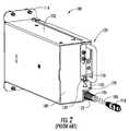
- FIG. 1is a front perspective view of a prior art pre-connectorized data center network apparatus as a connector package in the form of an integrated trunk module (ITM) having multiple connector adapters.
- ITMintegrated trunk module
- FIG. 2is a rear perspective view of the prior art ITM of FIG. 1 , illustrating a pre-connectorized fiber optic cable, cable exit point, pull handle and locking mechanism.
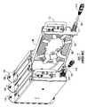
- FIG. 3is a rear perspective view of the prior art ITM of FIG. 1 shown with the storage tray in an opened and pivoted position.
- FIG. 4is a perspective view of the prior art ITM of FIG. 3 , shown with the storage tray in an opened and pivoted position and illustrating the transition lid.
- FIG. 5is a detailed perspective view of the prior art ITM of FIG. 1 , illustrating the strain relief feature and flexible boot for fiber optic cable exiting the ITM housing.
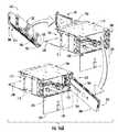
- FIG. 6is a perspective view of the prior art ITM of FIG. 1 , shown with the storage tray in an opened and pivoted position.
- FIG. 7is a perspective view of multiple prior art ITMs arranged in parallel, with one of the storage trays in the open and pivoted position.
- FIG. 8Ais a perspective view and FIG. 8B is a side view of an example cable network interconnection system (“ITM system”) that includes an ITM connector package and a cable package.
- ITM systemcable network interconnection system
- FIG. 9Ais a perspective view similar to FIG. 8A
- FIG. 9Bis a side view similar to FIG. 8B , where the cable package includes a cable support in the form of a reel.
- FIG. 10is a close-up perspective view of an example reel cable support.
- FIG. 11is a perspective view and FIG. 12 and FIG. 13 are respective side-on and end-on views of an example ITM system, wherein the ITM and the cable support are arranged in a stacked configuration.
- FIG. 14 and FIG. 15are perspective views of an example interconnection apparatus configured to support multiple ITMs.
- FIG. 16Ais a perspective view of an example interconnection apparatus and the ITM system, illustrating an example method of installing the ITM system in the interconnection apparatus so that the cable support extends from the housing rear in preparation for deploying the fiber optic cable from the cable support.
- FIG. 16Bis a close-up rear view of the interconnection apparatus and the ITM system installed therein, illustrating the uncoiling of the fiber optic cable from the cable support in the process of deploying the fiber optic cable.
- FIG. 16Cis similar to FIG. 16B , and shows the fiber optic cable uncoiled and the multifiber connector ready to be connected to a predetermined location.
- FIG. 17 and FIG. 18are perspective and top-down views, respectively, of the interconnection apparatus of FIG. 14 and FIG. 15 , shown with multiple ITM systems installed therein.
- ITM 100an apparatus in the form of an integrated trunk module (ITM) connector package 100 (hereinafter, ITM 100 ).
- ITM 100includes a housing 102 , a cable storage tray 104 slidably and pivotally attached to the housing 102 , a length of cable (“cable”) 106 , which can be copper or optical fiber cable, and at least one connector adapter 108 (multiple connector adapters are shown by way of illustration).
- cablelong-connector system or field connectors
- Factory pre-connector system or field connectorscan be used in any aspect of the present disclosure.
- a front end 110 of the ITM 100defines one or more slots 112 arranged in any number of rows or columns operable for receiving and securing the at least one adapter 108 within.
- the ITM 100includes a single row of slots 112 with each slot receiving a single SC duplex adapter 108 for a total of six adapters 108 providing connection points for twelve SC connectors.
- the ITM 100may include any number of connector adapter or connector receiving sites capable of accommodating any type and number of connectors.
- the adapters 108include removable covers 114 for protecting unpopulated adapters until needed.
- the front end 110further includes attachment features 116 for removably securing the ITM 100 to or within a distribution frame, interconnection apparatus or other mounting structure.
- the attachment features 116include a plunger and grommet configuration that allows for the ITM 100 to be installed or removed without the use of tools.
- the housing 102 and cable storage tray 104together define a cable storage cavity 105 for storing a length of pre-connectorized cable 106 that may be manually coiled or un-coiled as needed and routed to a predetermined location within the network.
- ITM 100is discussed herein as but one an example of a more general connector package, which generally can compromise fewer components than the modular embodiment of ITM 100 , while being configured to store or otherwise support a length of pre-connectorized cable 106 .
- the connector package 100can include a shelf (e.g., storage tray 104 ), a drawer, or just an adapter panel (e.g., just ITM front end 110 ), all without having housing 102 .
- a shelfe.g., storage tray 104
- drawere.g., just an adapter panel (e.g., just ITM front end 110 )
- the cable 106is shown terminating at one end in a multi-fiber connector 118 .
- a multi-fiber connector 118an MTP connector is shown, it is envisioned that the cable 106 may terminate in any type of single fiber or multi-fiber connector, but preferably terminates in a multi-fiber connector.
- the other end of the cableterminates in at least one connector, and preferably a plurality of single fiber connectors such as SC or LC connectors.
- the cable 106is routed within the ITM 100 through a transition lid (described in detail below) where the at least one, and preferably a plurality of, connectors are routed to the backside of the at least one adapter 108 .
- ITM 100is capable of receiving at least one connector from the inside of the ITM 100 from the cable 106 , and at least one connector from another source from the outside of the ITM.
- the mating connectorsmay be of like configuration or may be different.
- the at least one adapter 108may be a standard adapter or a hybrid adapter. Although not shown, each at least one adapter 108 may include a connector alignment sleeve.
- the cable 106has a predetermined length and is stored within ITM and is coiled and uncoiled in order to provide an adequate length for routing the multi-fiber connector 118 to the predetermined location.
- FIG. 2shows a rear perspective view of ITM 100 .
- the rear side 120 of the ITM 100and specifically the storage tray 104 , includes a pre-connectorized cable exit point 122 , a transition boot 124 positioned within the exit point 122 for transitioning the cable from within to outside of the ITM 100 , a pull handle 126 for pulling out and pushing in the storage tray 104 as needed, and a tray locking mechanism 128 .
- the handle 126may be replaced with any feature capable of being grasped to operate the storage tray 104 .
- the locking mechanism 128is operable for preventing the storage tray 104 from being unintentionally opened when a strong pull on the cable 106 occurs.
- the lock mechanism 128 shownincludes a plunger 130 and bracket 132 .
- the plunger 130is pulled up and the bracket 132 lifted, and the tray 104 is then opened.
- the tray 104is closed, the bracket 132 is pushed down against a bracket receiving tab, and the plunger 130 is pushed down to secure the bracket 132 against the tab of the housing 102 .
- the storage tray 104is shown in an opened and pivoted configuration.
- the storage tray 104includes at least one cable maintaining and retaining feature 134 .
- the at least one feature 134is operable for maintaining the cable 106 in a coiled configuration without violating the minimum band radius of the fiber.
- the length of coiled cablemay be of any length. ITM 100 width may be determined by the amount of slack contained within.
- the cable lengthis wound around the at least one feature 134 during shipping and deployment and uncoiled as needed.
- the cable lengthmay range from about 1 foot to several hundred feet in length, preferably from about 1 foot to about 100 feet in length.
- the cable 106may be coiled in either direction and is preferably coiled so that each end of the cable is smoothly routed to its respective predetermined destinations within the ITM 100 without introducing sharp bends in the cable.
- the cable 106may further be coiled with a length of slack free from the coil to allow the storage tray 104 to be extended without pulling on the cable.
- the cable 106exits the ITM 100 through the exit point 122 .
- the cable 106is fed through the cable transition boot 124 .
- the transition boot 124is retained within the exit point 122 .
- the flexible transition boot 124prevents kinking or sharp bending in the cable adjacent the storage tray 104 .
- the transition boot 124may provide partial strain relief to the cable 106 when the boot 124 is inserted into the exit point 122 and the exit point recess compresses the boot 124 .
- the transition boot 124may include ridges on the interior surface such that when the boot is squeezed when slid into the storage tray slot, strain relief and partial or total sealing may occur.
- the ITM 100may be designed to be either left- or right-opened, and the exiting cable 106 may be located at either the top of the bottom of the ITM.
- the storage tray 104is shown in an opened and pivoted configuration in order to illustrate the internal cavity 105 of the ITM 100 and the transition lid 136 .
- Internal cavity 105includes a first internal cavity portion 105 A for cable storage and a second cavity portion 105 B for cable routing to the at least one adapter.
- the first and second cavity portionsare separated by the transition lid 136 , also referred to herein as the “false bottom.”
- the transition lid 136may define an opening 138 for transitioning the cable 106 from the first cavity portion 105 A to the second cavity portion 105 B.
- the transition lid 136may further provide protection to the pigtailed end of the cable 106 when the ITM 100 is accessed to coil or uncoil the cable 106 .
- the transition lid 136hides/covers the routing of the 12 fibers to their respective adapters 108 .
- a single fiber connectormay be mounted in place of the multi-fiber connector, and a splitter or other signal splitting device may be mounted within the ITM, for example within the second cavity portion 105 B, thus allowing multiple fibers to be routed to the adapters.
- the cable strain relief and transition boot 124are shown in detail.
- the cable 106may be strain relieved to the storage tray 104 to relieve the internal remaining length of cable from pulling forces applied to the external portion of the cable.
- the cablemay be partially strain relieved using the transition boot 124 as described above.
- the cablemay also be strain relieved using a grommet 140 that is secured to a surface of the tray 104 , preferably an interior surface.
- the cablemay also be strain relieved using any other method known in the art including, but not limited to, cable ties.
- the housing 102includes channels or slots 142 positioned along the length of each side of the housing that provide a track for guiding and maintaining rollers 144 or wheels of the storage tray 104 .
- the sliding and pivoting movements of the storage tray 104are supported by the rollers 144 .
- the trayis prevented from twisting before the end of the movement.
- at least one of the rollers 144 of each side of the storage tray 104may extend into a pivot allowing slot 146 routed at a predetermined angle off of the tracks 142 .
- the storage tray 104may pivot up to about 90 degrees relative to the longitudinal axis of the ITM, more preferably up to about 45 degrees. A predetermined maximum pivot may be provided to prevent the storage tray 104 from contacting an adjacent ITM. As shown, the storage tray 104 is rotated about 40 degrees relative to the longitudinal axis of the ITM.
- Example interconnection apparatus in which the ITMs 100 may be installedinclude the PretiumTM Connector Housing family available from Corning Cable Systems of Hickory, N.C.
- a specific installation environmentmay include installation within a data center into a PCH-04U connector housing, available from Corning Cable Systems.
- the storage tray 104 of the middle positioned ITM 100is shown in the fully extended position and is also pivoted, thus providing ready access to the cable length.
- the housing, storage tray and other componentsmay be made from various materials such as, but not limited to, plastics, metals, combinations and the like depending upon installation environments.
- the transition bootis preferably made from a flexible material.
- the ITM dimensionsmay vary depending upon the amount of cable storage required and the number of adapters. Some embodiments do not require tools for the operation of mounting the ITM, accessing the storage tray, or coiling and uncoiling the cable length.
- the ITMs described aboveprovide rear side access to the cable length and do not require the ITM to be removed from its mounting position to access the cable length.
- Alternative ITM designsmay include sliding-only storage trays or pivoting-only storage trays.
- the pre-connectorized cable 106may include any type of optical fiber including, but not limited to, bend performance optical fiber, also referred to as bend insensitive optical fiber or bend optimized optical fiber.
- Bend performance fiberincludes microstructured optical fibers comprising a core region and a cladding region surrounding the core region, the cladding region comprising an annular hole-containing region comprised of non-periodically disposed holes such that the optical fiber is capable of single mode transmission at one or more wavelengths in one or more operating wavelength ranges.
- the core region and cladding regionprovide improved bend resistance, and single mode operation at wavelengths preferably greater than or equal to 1500 nm, in some embodiments also greater than 1400 nm, in other embodiments also greater than 1260 nm.
- the optical fibersprovide a mode field at a wavelength of 1310 nm preferably greater than 8.0 microns, more preferably between 8.0 and 10.0 microns.
- the bend performance fiberis thus single-mode transmission optical fiber.
- the connector packagehas dimensions determined by the size of the apparatus (e.g., interconnection apparatus) in which the connector package is to be installed. This defines the allowable size of the connector package and sets limit on the amount of cable 106 that can be stored within the connector package.
- the apparatuse.g., interconnection apparatus
- two different example ITMs of conventional sizehave respective internal cavities 105 that can respectively store 40 feet and 80 feet of cable 106 .
- FIG. 8Ais a perspective view and FIG. 8B is a side view of an example pre-connectorized cable network interconnection system or ITM system 200 that includes a connector package in the form of the example ITM 100 discussed above, and also includes a cable package 206 .
- the ITM 100 and cable package 206 set out in the embodiments of the present disclosurecan include a cable support 210 , as discussed below.
- the cable support 210can comprise a reel, as set out in detail herein, or alternatively comprise one or more generally flat supports, or a conical reel, cylinder, core, pay off, drum, tube, spool, one or more rods or beams, or a cable accumulator.
- the cable support 210can be rectangular as set out in detail herein, or alternative shapes can be used for example, square, round, oval, or any other suitable shape. In embodiments such as shown in FIGS. 8A and 8B , where no cable support 210 is used, one or more straps 207 can be used to hold cable 106 in a given collected (coiled, wrapped, bundled, or rolled) configuration.
- the cable 106 disposed on the cable support 210can be arranged in exemplary configurations including coiled as set out in detail herein, or it could be arranged in a spiral, undulated, serpentine, or arcuate bundles, rolled, wrapped, or wound on the cable support. More than one cable support 210 can be attached in series in a concatenated configuration.
- the cable package 206can be configured with no cable support, and in this case could be a spiral, undulated, serpentine, or bundles of cable or a coil, roll, wrapping, or winding of cable. More than one cable 106 can be included in the cable package.
- the cable 106can include one or more optical fibers, can include one or more copper conductors, or can include one or more hybrid optical fiber-copper cables. If more than one cable is used, the cable length can be the same or different.
- ITM system 200can be used in interconnection applications beyond data centers, for example, central office applications, and installations in the outside plant structures.
- FIG. 9Ais a perspective view similar to FIG. 8A and FIG. 9B is a side view similar to FIG. 8B and illustrate an example ITM system 200 with the cable package 206 , which includes an example cable support 210 in the form of a reel.
- ITM 100is shown as having a longitudinal axis A 1 and the cable support 210 is shown as having a longitudinal axis A 2 .
- a first portion of the cable 106 of length LC 1can be stored within the ITM internal cavity 105 as described above, while a second portion of the cable of length LC 2 can be stored on the cable support 210 .
- LC 1⁇ LC 2 .
- FIG. 9A and FIG. 9Bshow the ITM system 200 in an in-line configuration wherein ITM 100 and cable support 210 are arranged so that they are lined up generally along their respective longitudinal axes A 1 and A 2 .
- FIG. 10is a close-up perspective view of an example reel cable support 210 .
- the cable support 210includes two opposing, generally rectangular and planar top and bottom flanges 220 .
- Each flange 220includes an inner surface 222 , an outer surface 224 , sides 226 and ends 228 .
- Flanges 220have a width WF, a height HF and a length LF.
- flanges 220are made from corrugated plastic, which is light-weight, flexible, and generally does not produce dust or particles when handled or subjected to chafing.
- the flanges 220are connected at their respective centers by an elongate (e.g., generally rectangular or oval) central hub 230 that extends in the long (axial) direction of the flanges.
- the hub 230has an outer surface 232 and has a width WH, a height HH and a length LH.
- An example generally rectangular hub 230has four rounded corners 234 each with a radius of curvature RC suitable for not exceeding the bend limit of the cable 106 .
- the hub 230is made from a lightweight material such as polypropylene, polystyrene, extruded polystyrene foam (i.e., STYROFOAM), polyethylene, engineering plastics, and combinations thereof. Such material is useful for protecting cable 106 when it is coiled around hub 230 .
- cable package 206has a width WR, a height HR and a length LR.
- at least one cable package dimensionis defined by at least one the cable support dimension, e.g., in the case where cable 106 does not extend beyond the confines of the cable support that corresponds to the at least one dimension.
- at least one of the cable package height HR, width WR and length LRis at least one of the cable support height, width and length.
- ITM 100has a width WM, a height HM and a length LM.
- the cable package height HRis substantially the same as module height HM, i.e., the cable package height can be slightly bigger than the module height, as long as the cable package can fit into the interconnection apparatus.
- the hub inner surface 232 and the opposing flange inner surfaces 222define an open storage area 240 where the cable 106 is stored when coiled around the hub 230 , as shown in FIG. 9A and FIG. 9B .
- the cable support 210includes a guiding aperture (notch) 250 formed in one of the flanges 220 , with the notch sized to loosely hold and guide cable 106 as the cable transitions from the ITM 100 to the cable support 210 .
- Notch 250also serves to prevent a transition portion 106 T of the cable 106 from being pinched between the ITM 100 and cable support 210 .
- the transition portion 106 Tmay be, for example, an inch to several inches in length. Note that in an example, the transition portion 106 T passes through the transition boot 124 .
- an example of the cable support 210includes a central hole 260 and two smaller peripheral holes 262 on either side of the central hole along the cable support longitudinal axis A 2 . These holes can be used to facilitate coiling and uncoiling the cable 106 onto and from the cable support 210 .
- a coiling fixture(not shown) having three prongs that engage holes 260 and 262 is used to mechanically coil and uncoil the cable 106 into or from the cable support 210 .
- one of the peripheral holes 262is used to accommodate a strap 263 (see FIG.
- FIG. 11is a perspective view and FIG. 12 and FIG. 13 are respective side-on and end-on views of an example ITM system 200 , wherein the ITM 100 and the cable package 206 are arranged in a stacked configuration with their respective longitudinal axes A 1 and A 2 now generally parallel to one another ( FIG. 12 ).
- this stacked configuration of the ITM system 200is maintained using, for example, simple fixing means such as VELCROTM, an adhesive strap (not shown), strapping tape, etc.
- the stacked configuration of ITM the system 200is useful for transporting the ITM system in anticipation of future deployment.
- FIG. 14 and FIG. 15are perspective views of an example interconnection apparatus 300 shown in the form of a connector housing.
- Interconnection apparatus 300is configured to support multiple ITMs 100 . Cartesian coordinates are shown in FIGS. 14 and 15 for the sake of reference.
- the interconnection apparatus 300has a front end 302 , a rear end 304 , and includes a bottom panel 310 with front and rear edges 312 and 314 .
- the interconnection apparatus 300also includes opposing side panels 316 , a folding front panel 330 connected to the bottom panel front edge 312 , and a folding rear panel 334 attached to the bottom panel rear edge 314 .
- the interconnection apparatus 300also includes a top panel 340 attached to side panels 316 .
- the side panels 316 and top and bottom panels 340 and 310define a rectangular interior 350 of height H 1 .
- Bottom panel 310 and top panel 340include guides 360 used to guide and support ITMs 100 as they are inserted into interconnection apparatus interior 350 .
- Folding front panel 330folds upward to close off interior 350 at front end 302
- folding rear panel 334folds upward to close off interior 350 at rear end 304 .
- a mounting frame 356runs around the bottom panel front edge and the front sidewall panel edges and includes securing features 358 (e.g., holes) for securing (mounting) the ITMs 100 to the interconnection apparatus, as well as for securing the interconnection apparatus to a larger apparatus, such as distribution panel or frame (not shown).
- the ITM width WM and the ITM height HMare sized so that the ITM 100 can slide into the interconnection apparatus 300 at front end 352 oriented as shown in FIG. 15 , (i.e., with the ITM 100 oriented with its height HM along the Y-direction) and reside in interior 350 .
- the cable package height HRhas to be less than the interconnection apparatus interior height (i.e., HR ⁇ H 1 ).
- the cable package width WRhas to be equal to or less than the module width (i.e., WR ⁇ WM).
- the cable package height HRis equal to or less than the module height HM (i.e., HR ⁇ HM).
- at least one of the cable package dimensionsis defined by at least one cable support dimension.
- a method of deploying cable 106 in cable networkincludes providing the ITM system 200 in a stacked configuration ( FIGS. 11-13 ) and delivering it to interconnection apparatus 300 .
- Cable package 206 and ITM 100are then taken out of the stacked configuration and placed in the in-line configuration ( FIGS. 8A-9B ).
- the interconnection apparatus 300includes a front panel that has slots (not shown) that need to be uncovered for inserting ITMs 100 , the slot covers are removed.
- Cable package 206is then feed into interconnection apparatus interior 350 at front end 302 (through the aforementioned slots, if necessary) with its height HR along the Y-direction.
- Cable package 206is then passed through the interconnection apparatus interior 350 (see also FIG. 15 ) and out of the interconnection apparatus rear end 304 . This allows for ITM 100 to then be placed in interconnection apparatus interior 350 and secured to interconnection apparatus 300 at front end 302 . This process is repeated for other ITM systems 200 until interconnection apparatus is filled with ITM systems 200 , as illustrated in the perspective and top-down views of FIG. 17 and FIG. 18 .
- the cable 106may then be deployed by uncoiling the cable, e.g., from cable support 210 ( FIG. 16B ) and routing the multi-fiber connector 118 to its predetermined destination ( FIG. 16C ). At this point, if a cable support 210 is used in cable package 206 , the able support can be discarded or recycled for use in forming another ITM system 200 .
- a method of installing a cable 106 in interconnection apparatus 300includes providing a connector package 100 having at least one connector adapter 108 , the connector package configured to support a portion of a connectorized cable 106 , with one cable end connected to the at least one connector adapter and another cable end connected to a connector.
- the methodalso includes providing at least one cable package 206 , the cable package including at least one length of the cable 106 , and the cable package storing a portion of the cable on substantially the exterior of the connector package.
- the cable package 206is sized to pass through the interconnection apparatus interior 305 from the front opening 352 to the rear opening 354 as the connector package is inserted in the interconnection apparatus.
Landscapes
- Physics & Mathematics (AREA)
- General Physics & Mathematics (AREA)
- Optics & Photonics (AREA)
- Engineering & Computer Science (AREA)
- Computer Networks & Wireless Communication (AREA)
- Light Guides In General And Applications Therefor (AREA)
Abstract
Description
Claims (30)
Priority Applications (1)
| Application Number | Priority Date | Filing Date | Title |
|---|---|---|---|
| US12/780,238US8301003B2 (en) | 2010-05-14 | 2010-05-14 | Cable network interconnection system with connector package and cable package |
Applications Claiming Priority (1)
| Application Number | Priority Date | Filing Date | Title |
|---|---|---|---|
| US12/780,238US8301003B2 (en) | 2010-05-14 | 2010-05-14 | Cable network interconnection system with connector package and cable package |
Publications (2)
| Publication Number | Publication Date |
|---|---|
| US20110280536A1 US20110280536A1 (en) | 2011-11-17 |
| US8301003B2true US8301003B2 (en) | 2012-10-30 |
Family
ID=44911843
Family Applications (1)
| Application Number | Title | Priority Date | Filing Date |
|---|---|---|---|
| US12/780,238Expired - Fee RelatedUS8301003B2 (en) | 2010-05-14 | 2010-05-14 | Cable network interconnection system with connector package and cable package |
Country Status (1)
| Country | Link |
|---|---|
| US (1) | US8301003B2 (en) |
Cited By (31)
| Publication number | Priority date | Publication date | Assignee | Title |
|---|---|---|---|---|
| US8532490B2 (en) | 2009-03-05 | 2013-09-10 | Adc Telecommunications, Inc. | Methods, systems and devices for integrating wireless technology into a fiber optic network |
| US8837940B2 (en) | 2010-04-14 | 2014-09-16 | Adc Telecommunications, Inc. | Methods and systems for distributing fiber optic telecommunication services to local areas and for supporting distributed antenna systems |
| US9078287B2 (en) | 2010-04-14 | 2015-07-07 | Adc Telecommunications, Inc. | Fiber to the antenna |
| US9291786B2 (en) | 2013-12-31 | 2016-03-22 | All Systems Broadband, Inc. | Grommet for fiber optic enclosures |
| US9472314B2 (en) | 2013-05-14 | 2016-10-18 | Commscope Technologies Llc | Power/fiber hybrid cable |
| US9557505B2 (en) | 2013-03-18 | 2017-01-31 | Commscope Technologies Llc | Power and optical fiber interface |
| RU2623812C2 (en)* | 2014-05-22 | 2017-06-29 | Марко Зюстеманалюзе Унд Энтвиклюнг Гмбх | Light conducting system |
| US9893811B2 (en) | 2013-03-18 | 2018-02-13 | Commscope Technologies Llc | Architecture for a wireless network |
| US10416406B1 (en) | 2018-03-01 | 2019-09-17 | Afl Telecommunications Llc | Communications module housing |
| US10451828B1 (en) | 2018-11-09 | 2019-10-22 | Afl Telecommunications Llc | Communications module housing |
| US11119546B2 (en) | 2016-11-09 | 2021-09-14 | Commscope, Inc. Of North Carolina | Exchangeable powered infrastructure module |
| US11187859B2 (en) | 2017-06-28 | 2021-11-30 | Corning Research & Development Corporation | Fiber optic connectors and methods of making the same |
| US11215768B2 (en) | 2017-06-28 | 2022-01-04 | Corning Research & Development Corporation | Fiber optic connectors and connectorization employing adhesive admitting adapters |
| US11294133B2 (en) | 2019-07-31 | 2022-04-05 | Corning Research & Development Corporation | Fiber optic networks using multiports and cable assemblies with cable-to-connector orientation |
| US11300746B2 (en) | 2017-06-28 | 2022-04-12 | Corning Research & Development Corporation | Fiber optic port module inserts, assemblies and methods of making the same |
| US11487073B2 (en) | 2019-09-30 | 2022-11-01 | Corning Research & Development Corporation | Cable input devices having an integrated locking feature and assemblies using the cable input devices |
| US11536921B2 (en) | 2020-02-11 | 2022-12-27 | Corning Research & Development Corporation | Fiber optic terminals having one or more loopback assemblies |
| US11604320B2 (en) | 2020-09-30 | 2023-03-14 | Corning Research & Development Corporation | Connector assemblies for telecommunication enclosures |
| US11650388B2 (en) | 2019-11-14 | 2023-05-16 | Corning Research & Development Corporation | Fiber optic networks having a self-supporting optical terminal and methods of installing the optical terminal |
| US11668890B2 (en) | 2017-06-28 | 2023-06-06 | Corning Research & Development Corporation | Multiports and other devices having optical connection ports with securing features and methods of making the same |
| US11686913B2 (en) | 2020-11-30 | 2023-06-27 | Corning Research & Development Corporation | Fiber optic cable assemblies and connector assemblies having a crimp ring and crimp body and methods of fabricating the same |
| US11703646B2 (en) | 2017-06-28 | 2023-07-18 | Corning Research & Development Corporation | Multiports and optical connectors with rotationally discrete locking and keying features |
| US11880076B2 (en) | 2020-11-30 | 2024-01-23 | Corning Research & Development Corporation | Fiber optic adapter assemblies including a conversion housing and a release housing |
| US11886010B2 (en) | 2019-10-07 | 2024-01-30 | Corning Research & Development Corporation | Fiber optic terminals and fiber optic networks having variable ratio couplers |
| US11927810B2 (en) | 2020-11-30 | 2024-03-12 | Corning Research & Development Corporation | Fiber optic adapter assemblies including a conversion housing and a release member |
| US11947167B2 (en) | 2021-05-26 | 2024-04-02 | Corning Research & Development Corporation | Fiber optic terminals and tools and methods for adjusting a split ratio of a fiber optic terminal |
| US11994722B2 (en) | 2020-11-30 | 2024-05-28 | Corning Research & Development Corporation | Fiber optic adapter assemblies including an adapter housing and a locking housing |
| US12019279B2 (en) | 2019-05-31 | 2024-06-25 | Corning Research & Development Corporation | Multiports and other devices having optical connection ports with sliding actuators and methods of making the same |
| US12044894B2 (en) | 2018-12-28 | 2024-07-23 | Corning Research & Development Corporation | Multiport assemblies including mounting features or dust plugs |
| US12271040B2 (en) | 2017-06-28 | 2025-04-08 | Corning Research & Development Corporation | Fiber optic extender ports, assemblies and methods of making the same |
| US12372727B2 (en) | 2020-10-30 | 2025-07-29 | Corning Research & Development Corporation | Female fiber optic connectors having a rocker latch arm and methods of making the same |
Families Citing this family (4)
| Publication number | Priority date | Publication date | Assignee | Title |
|---|---|---|---|---|
| US8301003B2 (en)* | 2010-05-14 | 2012-10-30 | Corning Cable Systems Llc | Cable network interconnection system with connector package and cable package |
| CA2834781C (en) | 2011-05-13 | 2019-02-05 | Corning Cable Systems Llc | Transformable cable reels and related assemblies and methods |
| WO2016068984A1 (en) | 2014-10-31 | 2016-05-06 | Hewlett Packard Enterprise Development Lp | Cable storage module |
| US12360327B2 (en) | 2019-10-17 | 2025-07-15 | Commscope Technologies Llc | Rack mounted enclosure |
Citations (8)
| Publication number | Priority date | Publication date | Assignee | Title |
|---|---|---|---|---|
| JPH09269422A (en) | 1996-03-29 | 1997-10-14 | Fujikura Ltd | Extra length storage case for optical fiber core and extra length storage method |
| US6058235A (en)* | 1998-06-23 | 2000-05-02 | Fujitsu Limited | Line terminating device |
| US20050117376A1 (en)* | 2001-12-03 | 2005-06-02 | John Wilson | Power converter with retractable cable system |
| US20060210230A1 (en) | 2005-03-16 | 2006-09-21 | Fiber Optic Cable Storage, Inc. | Fiber optic storing and dispensing apparatus |
| US7346253B2 (en)* | 2003-12-24 | 2008-03-18 | Corning Cable Systems Llc | Fiber optic drop cable slack storage receptacle |
| US20080131067A1 (en)* | 2006-08-31 | 2008-06-05 | Ugolini Alan W | Pre-connectorized fiber optic cable network interconnection apparatus |
| US20100329621A1 (en)* | 2009-06-26 | 2010-12-30 | Elli Makrides-Saravanos | Fiber Optic Cable Slack Storage Module |
| US20110280536A1 (en)* | 2010-05-14 | 2011-11-17 | De Los Santos Campos Cesar A | Cable network interconnection system with connector package and cable package |
- 2010
- 2010-05-14USUS12/780,238patent/US8301003B2/ennot_activeExpired - Fee Related
Patent Citations (10)
| Publication number | Priority date | Publication date | Assignee | Title |
|---|---|---|---|---|
| JPH09269422A (en) | 1996-03-29 | 1997-10-14 | Fujikura Ltd | Extra length storage case for optical fiber core and extra length storage method |
| US6058235A (en)* | 1998-06-23 | 2000-05-02 | Fujitsu Limited | Line terminating device |
| US20050117376A1 (en)* | 2001-12-03 | 2005-06-02 | John Wilson | Power converter with retractable cable system |
| US7554828B2 (en)* | 2001-12-03 | 2009-06-30 | Igo, Inc. | Power converter with retractable cable system |
| US7346253B2 (en)* | 2003-12-24 | 2008-03-18 | Corning Cable Systems Llc | Fiber optic drop cable slack storage receptacle |
| US20060210230A1 (en) | 2005-03-16 | 2006-09-21 | Fiber Optic Cable Storage, Inc. | Fiber optic storing and dispensing apparatus |
| US20080131067A1 (en)* | 2006-08-31 | 2008-06-05 | Ugolini Alan W | Pre-connectorized fiber optic cable network interconnection apparatus |
| US7391952B1 (en) | 2006-08-31 | 2008-06-24 | Corning Cable Systems Llc | Pre-connectorized fiber optic cable network interconnection apparatus |
| US20100329621A1 (en)* | 2009-06-26 | 2010-12-30 | Elli Makrides-Saravanos | Fiber Optic Cable Slack Storage Module |
| US20110280536A1 (en)* | 2010-05-14 | 2011-11-17 | De Los Santos Campos Cesar A | Cable network interconnection system with connector package and cable package |
Cited By (91)
| Publication number | Priority date | Publication date | Assignee | Title |
|---|---|---|---|---|
| US9893813B2 (en) | 2009-03-05 | 2018-02-13 | Commscope Technologies Llc | Methods, systems, and devices for integrating wireless technology into a fiber optic network |
| US11438070B2 (en) | 2009-03-05 | 2022-09-06 | Commscope Technologies Llc | Methods, systems, and devices for integrating wireless technology into a fiber optic network |
| US8929740B2 (en) | 2009-03-05 | 2015-01-06 | Adc Telecommunications, Inc. | Methods, systems and devices for integrating wireless technology into a fiber optic network |
| US8532490B2 (en) | 2009-03-05 | 2013-09-10 | Adc Telecommunications, Inc. | Methods, systems and devices for integrating wireless technology into a fiber optic network |
| US11044014B2 (en) | 2009-03-05 | 2021-06-22 | Commscope Technologies Llc | Methods, systems, and devices for integrating wireless technology into a fiber optic network |
| US10630388B2 (en) | 2009-03-05 | 2020-04-21 | Commscope Technologies Llc | Methods, systems, and devices for integrating wireless technology into a fiber optic network |
| US9438342B2 (en) | 2009-03-05 | 2016-09-06 | Commscope Technologies Llc | Methods, systems, and devices for integrating wireless technology into a fiber optic network |
| US12149288B2 (en) | 2009-03-05 | 2024-11-19 | Commscope Technologies Llc | Methods, systems, and devices for integrating wireless technology into a fiber optic network |
| US10135534B2 (en) | 2009-03-05 | 2018-11-20 | Commscope Technologies Llc | Methods, systems, and devices for integrating wireless technology into a fiber optic network |
| US9553669B2 (en) | 2010-04-14 | 2017-01-24 | Commscope Technologies Llc | Fiber to the antenna |
| US9414137B2 (en) | 2010-04-14 | 2016-08-09 | Commscope Technologies Llc | Methods and systems for distributing fiber optic telecommunication services to local areas and for supporting distributed antenna systems |
| US8837940B2 (en) | 2010-04-14 | 2014-09-16 | Adc Telecommunications, Inc. | Methods and systems for distributing fiber optic telecommunication services to local areas and for supporting distributed antenna systems |
| US9888524B2 (en) | 2010-04-14 | 2018-02-06 | Commscope Technologies Llc | Fiber to the antenna |
| US9078287B2 (en) | 2010-04-14 | 2015-07-07 | Adc Telecommunications, Inc. | Fiber to the antenna |
| US10819444B2 (en) | 2010-04-14 | 2020-10-27 | Commscope Technologies Llc | Methods and systems for distributing fiber optic telecommunication services to local areas and for supporting distributed antenna systems |
| US11736192B2 (en) | 2010-04-14 | 2023-08-22 | Commscope Technologies Llc | Fiber to the antenna |
| US11259364B2 (en) | 2010-04-14 | 2022-02-22 | Commscope Technologies Llc | Fiber to the antenna |
| US10736179B2 (en) | 2010-04-14 | 2020-08-04 | Commscope Technologies Llc | Fiber to the antenna |
| US10292206B2 (en) | 2010-04-14 | 2019-05-14 | Commscope Technologies Llc | Fiber to the antenna |
| US9977208B2 (en) | 2013-03-18 | 2018-05-22 | Commscope Technologies Llc | Power and optical fiber interface |
| US11656418B2 (en) | 2013-03-18 | 2023-05-23 | Commscope Technologies Llc | Power and optical fiber interface |
| US10502912B2 (en) | 2013-03-18 | 2019-12-10 | Commscope Technologies Llc | Power and optical fiber interface |
| US12405435B2 (en) | 2013-03-18 | 2025-09-02 | Commscope Technologies Llc | Power and optical fiber interface |
| US11215776B2 (en) | 2013-03-18 | 2022-01-04 | Commscope Technologies Llc | Power and optical fiber interface |
| US9893811B2 (en) | 2013-03-18 | 2018-02-13 | Commscope Technologies Llc | Architecture for a wireless network |
| US9557505B2 (en) | 2013-03-18 | 2017-01-31 | Commscope Technologies Llc | Power and optical fiber interface |
| US10163548B2 (en) | 2013-05-14 | 2018-12-25 | Commscope Technologies Llc | Power/fiber hybrid cable |
| US10892068B2 (en) | 2013-05-14 | 2021-01-12 | Commscope Technologies Llc | Power/fiber hybrid cable |
| US9472314B2 (en) | 2013-05-14 | 2016-10-18 | Commscope Technologies Llc | Power/fiber hybrid cable |
| US9837186B2 (en) | 2013-05-14 | 2017-12-05 | Commscope Technologies Llc | Power/fiber hybrid cable |
| US9291786B2 (en) | 2013-12-31 | 2016-03-22 | All Systems Broadband, Inc. | Grommet for fiber optic enclosures |
| RU2623812C2 (en)* | 2014-05-22 | 2017-06-29 | Марко Зюстеманалюзе Унд Энтвиклюнг Гмбх | Light conducting system |
| US11119546B2 (en) | 2016-11-09 | 2021-09-14 | Commscope, Inc. Of North Carolina | Exchangeable powered infrastructure module |
| US11493700B2 (en) | 2017-06-28 | 2022-11-08 | Corning Research & Development Corporation | Compact fiber optic connectors, cable assemblies and methods of making the same |
| US11886017B2 (en) | 2017-06-28 | 2024-01-30 | Corning Research & Development Corporation | Multiports and other devices having connection ports with securing features and methods of making the same |
| US11287582B2 (en) | 2017-06-28 | 2022-03-29 | Corning Research & Development Corporation | Compact fiber optic connectors, cable assemblies and methods of making the same |
| US12429655B2 (en) | 2017-06-28 | 2025-09-30 | Corning Optical Communications LLC | Multiports having connection ports with associated securing features and methods of making the same |
| US11300746B2 (en) | 2017-06-28 | 2022-04-12 | Corning Research & Development Corporation | Fiber optic port module inserts, assemblies and methods of making the same |
| US11327247B2 (en) | 2017-06-28 | 2022-05-10 | Corning Optical Communications LLC | Multiports having connection ports formed in the shell and associated securing features |
| US11409055B2 (en) | 2017-06-28 | 2022-08-09 | Corning Optical Communications LLC | Multiports having connection ports with associated securing features and methods of making the same |
| US11415759B2 (en) | 2017-06-28 | 2022-08-16 | Corning Optical Communications LLC | Multiports having a connection port insert and methods of making the same |
| US11215768B2 (en) | 2017-06-28 | 2022-01-04 | Corning Research & Development Corporation | Fiber optic connectors and connectorization employing adhesive admitting adapters |
| US11460646B2 (en) | 2017-06-28 | 2022-10-04 | Corning Research & Development Corporation | Fiber optic connectors and multiport assemblies including retention features |
| US11487065B2 (en) | 2017-06-28 | 2022-11-01 | Corning Research & Development Corporation | Multiports and devices having a connector port with a rotating securing feature |
| US12379551B2 (en) | 2017-06-28 | 2025-08-05 | Corning Optical Communications LLC | Multiports having connection ports formed in the shell and associated securing features |
| US11187859B2 (en) | 2017-06-28 | 2021-11-30 | Corning Research & Development Corporation | Fiber optic connectors and methods of making the same |
| US11493699B2 (en) | 2017-06-28 | 2022-11-08 | Corning Research & Development Corporation | Multifiber fiber optic connectors, cable assemblies and methods of making the same |
| US11531168B2 (en) | 2017-06-28 | 2022-12-20 | Corning Research & Development Corporation | Fiber optic connectors having a keying structure and methods of making the same |
| US12379552B2 (en) | 2017-06-28 | 2025-08-05 | Corning Research & Development Corporation | Compact fiber optic connectors, cable assemblies and methods of making the same |
| US11536913B2 (en) | 2017-06-28 | 2022-12-27 | Corning Research & Development Corporation | Fiber optic connectors and connectorization employing adhesive admitting adapters |
| US11543600B2 (en) | 2017-06-28 | 2023-01-03 | Corning Research & Development Corporation | Compact fiber optic connectors having multiple connector footprints, along with cable assemblies and methods of making the same |
| US11579377B2 (en) | 2017-06-28 | 2023-02-14 | Corning Research & Development Corporation | Compact fiber optic connectors, cable assemblies and methods of making the same with alignment elements |
| US12353025B2 (en) | 2017-06-28 | 2025-07-08 | Corning Optical Communications LLC | Multiports having a connection port insert and methods of making the same |
| US11624877B2 (en) | 2017-06-28 | 2023-04-11 | Corning Research & Development Corporation | Multiports having connection ports with securing features that actuate flexures and methods of making the same |
| US12353024B2 (en) | 2017-06-28 | 2025-07-08 | Corning Research & Development Corporation | Multiports and optical connectors with rotationally discrete locking and keying features |
| US12298568B2 (en) | 2017-06-28 | 2025-05-13 | Corning Research & Development Corporation | Fiber optic connectors and multiport assemblies including retention features |
| US11656414B2 (en) | 2017-06-28 | 2023-05-23 | Corning Research & Development Corporation | Multiports and other devices having connection ports with securing features and methods of making the same |
| US11668890B2 (en) | 2017-06-28 | 2023-06-06 | Corning Research & Development Corporation | Multiports and other devices having optical connection ports with securing features and methods of making the same |
| US12276846B2 (en) | 2017-06-28 | 2025-04-15 | Corning Research & Development Corporation | Compact fiber optic connectors, cable assemblies and methods of making the same |
| US11703646B2 (en) | 2017-06-28 | 2023-07-18 | Corning Research & Development Corporation | Multiports and optical connectors with rotationally discrete locking and keying features |
| US12271040B2 (en) | 2017-06-28 | 2025-04-08 | Corning Research & Development Corporation | Fiber optic extender ports, assemblies and methods of making the same |
| US11789214B2 (en) | 2017-06-28 | 2023-10-17 | Corning Research & Development Corporation | Multiports and other devices having keyed connection ports and securing features and methods of making the same |
| US12174432B2 (en) | 2017-06-28 | 2024-12-24 | Corning Research & Development Corporation | Fiber optic connectors and connectorization employing adhesive admitting adapters |
| US11262509B2 (en) | 2017-06-28 | 2022-03-01 | Corning Research & Development Corporation | Compact fiber optic connectors having multiple connector footprints, along with cable assemblies and methods of making the same |
| US12092878B2 (en) | 2017-06-28 | 2024-09-17 | Corning Research & Development Corporation | Fiber optic connectors having a keying structure and methods of making the same |
| US11906792B2 (en) | 2017-06-28 | 2024-02-20 | Corning Research & Development Corporation | Compact fiber optic connectors having multiple connector footprints, along with cable assemblies and methods of making the same |
| US11914197B2 (en) | 2017-06-28 | 2024-02-27 | Corning Research & Development Corporation | Compact fiber optic connectors having multiple connector footprints, along with cable assemblies and methods of making the same |
| US11914198B2 (en) | 2017-06-28 | 2024-02-27 | Corning Research & Development Corporation | Compact fiber optic connectors having multiple connector footprints, along with cable assemblies and methods of making the same |
| US12013578B2 (en) | 2017-06-28 | 2024-06-18 | Corning Research & Development Corporation | Multifiber fiber optic connectors, cable assemblies and methods of making the same |
| US11940656B2 (en) | 2017-06-28 | 2024-03-26 | Corning Research & Development Corporation | Compact fiber optic connectors, cable assemblies and methods of making the same |
| US11966089B2 (en) | 2017-06-28 | 2024-04-23 | Corning Optical Communications, Llc | Multiports having connection ports formed in the shell and associated securing features |
| US10416406B1 (en) | 2018-03-01 | 2019-09-17 | Afl Telecommunications Llc | Communications module housing |
| US10823927B2 (en) | 2018-03-01 | 2020-11-03 | Afl Telecommunications Llc | Communications module housing |
| US10802235B2 (en) | 2018-11-09 | 2020-10-13 | Afl Telecommunications Llc | Communications module housing |
| US10451828B1 (en) | 2018-11-09 | 2019-10-22 | Afl Telecommunications Llc | Communications module housing |
| US12044894B2 (en) | 2018-12-28 | 2024-07-23 | Corning Research & Development Corporation | Multiport assemblies including mounting features or dust plugs |
| US12019279B2 (en) | 2019-05-31 | 2024-06-25 | Corning Research & Development Corporation | Multiports and other devices having optical connection ports with sliding actuators and methods of making the same |
| US11294133B2 (en) | 2019-07-31 | 2022-04-05 | Corning Research & Development Corporation | Fiber optic networks using multiports and cable assemblies with cable-to-connector orientation |
| US11487073B2 (en) | 2019-09-30 | 2022-11-01 | Corning Research & Development Corporation | Cable input devices having an integrated locking feature and assemblies using the cable input devices |
| US11886010B2 (en) | 2019-10-07 | 2024-01-30 | Corning Research & Development Corporation | Fiber optic terminals and fiber optic networks having variable ratio couplers |
| US11650388B2 (en) | 2019-11-14 | 2023-05-16 | Corning Research & Development Corporation | Fiber optic networks having a self-supporting optical terminal and methods of installing the optical terminal |
| US11536921B2 (en) | 2020-02-11 | 2022-12-27 | Corning Research & Development Corporation | Fiber optic terminals having one or more loopback assemblies |
| US12019285B2 (en) | 2020-09-30 | 2024-06-25 | Corning Research & Development Corporation | Connector assemblies for telecommunication enclosures |
| US11604320B2 (en) | 2020-09-30 | 2023-03-14 | Corning Research & Development Corporation | Connector assemblies for telecommunication enclosures |
| US12372727B2 (en) | 2020-10-30 | 2025-07-29 | Corning Research & Development Corporation | Female fiber optic connectors having a rocker latch arm and methods of making the same |
| US12345927B2 (en) | 2020-11-30 | 2025-07-01 | Corning Research & Development Corporation | Fiber optic adapter assemblies including a conversion housing and a release housing |
| US11686913B2 (en) | 2020-11-30 | 2023-06-27 | Corning Research & Development Corporation | Fiber optic cable assemblies and connector assemblies having a crimp ring and crimp body and methods of fabricating the same |
| US11880076B2 (en) | 2020-11-30 | 2024-01-23 | Corning Research & Development Corporation | Fiber optic adapter assemblies including a conversion housing and a release housing |
| US11927810B2 (en) | 2020-11-30 | 2024-03-12 | Corning Research & Development Corporation | Fiber optic adapter assemblies including a conversion housing and a release member |
| US11994722B2 (en) | 2020-11-30 | 2024-05-28 | Corning Research & Development Corporation | Fiber optic adapter assemblies including an adapter housing and a locking housing |
| US11947167B2 (en) | 2021-05-26 | 2024-04-02 | Corning Research & Development Corporation | Fiber optic terminals and tools and methods for adjusting a split ratio of a fiber optic terminal |
Also Published As
| Publication number | Publication date |
|---|---|
| US20110280536A1 (en) | 2011-11-17 |
Similar Documents
| Publication | Publication Date | Title |
|---|---|---|
| US8301003B2 (en) | Cable network interconnection system with connector package and cable package | |
| US11513303B2 (en) | Optical fiber distribution systems and components | |
| EP3230780B1 (en) | Fiber optic cable slack management module | |
| US10996418B2 (en) | Connecting subscribers to a fiber optic network using a cable spool | |
| CN101512405B (en) | Pre-connectorized fiber optic cable network interconnection apparatus | |
| US9927591B2 (en) | Rapid deployment packaging for optical fiber | |
| US7245809B1 (en) | Splitter modules for fiber distribution hubs | |
| AU2008209645B2 (en) | Preconnectorized fiber optic cable assembly | |
| US20080037945A1 (en) | Cable payout systems and methods | |
| WO1991010927A1 (en) | Optical fiber cable distribution frame and support | |
| US20100080524A1 (en) | System for the Distribution of Optical Fibers | |
| CA2428253A1 (en) | Aerial closure for local convergence point | |
| US20110116757A1 (en) | Optical fibre distribution module with storage reels and organiser | |
| US11852882B2 (en) | Packaging assembly for telecommunications equipment | |
| WO2010001160A1 (en) | Optical fibre distribution system with fibre storage reels | |
| WO2010001155A2 (en) | Improvements in or relating to optical fibre distribution systems | |
| US9341806B2 (en) | Fan-out subassembly | |
| US20250147259A1 (en) | Fiber optic distribution module assembly | |
| WO2025101600A1 (en) | Preterminated network cable apparatus, system and methods |
Legal Events
| Date | Code | Title | Description |
|---|---|---|---|
| AS | Assignment | Owner name:CORNING CABLE SYSTEMS LLC, NORTH CAROLINA Free format text:ASSIGNMENT OF ASSIGNORS INTEREST;ASSIGNORS:DE LOS SANTOS CAMPOS, CESAR A.;DENNIS, ROBERT W.;LABORDE, MAXIMILIANO G.;AND OTHERS;SIGNING DATES FROM 20100512 TO 20100513;REEL/FRAME:024387/0239 | |
| ZAAA | Notice of allowance and fees due | Free format text:ORIGINAL CODE: NOA | |
| ZAAB | Notice of allowance mailed | Free format text:ORIGINAL CODE: MN/=. | |
| STCF | Information on status: patent grant | Free format text:PATENTED CASE | |
| AS | Assignment | Owner name:CORNING OPTICAL COMMUNICATIONS LLC, NORTH CAROLINA Free format text:CHANGE OF NAME;ASSIGNOR:CORNING CABLE SYSTEMS LLC;REEL/FRAME:033647/0231 Effective date:20131231 Owner name:CCS TECHNOLOGY, INC., DELAWARE Free format text:ASSIGNMENT OF ASSIGNORS INTEREST;ASSIGNOR:CORNING OPTICAL COMMUNICATIONS LLC;REEL/FRAME:033654/0945 Effective date:20140417 | |
| FPAY | Fee payment | Year of fee payment:4 | |
| AS | Assignment | Owner name:CORNING OPTICAL COMMUNICATIONS LLC, NORTH CAROLINA Free format text:MERGER;ASSIGNORS:CCS TECHNOLOGY, INC.;CORNING OPTICAL COMMUNICATIONS BRANDS, INC.;REEL/FRAME:043601/0427 Effective date:20170630 | |
| MAFP | Maintenance fee payment | Free format text:PAYMENT OF MAINTENANCE FEE, 8TH YEAR, LARGE ENTITY (ORIGINAL EVENT CODE: M1552); ENTITY STATUS OF PATENT OWNER: LARGE ENTITY Year of fee payment:8 | |
| FEPP | Fee payment procedure | Free format text:MAINTENANCE FEE REMINDER MAILED (ORIGINAL EVENT CODE: REM.); ENTITY STATUS OF PATENT OWNER: LARGE ENTITY | |
| LAPS | Lapse for failure to pay maintenance fees | Free format text:PATENT EXPIRED FOR FAILURE TO PAY MAINTENANCE FEES (ORIGINAL EVENT CODE: EXP.); ENTITY STATUS OF PATENT OWNER: LARGE ENTITY | |
| STCH | Information on status: patent discontinuation | Free format text:PATENT EXPIRED DUE TO NONPAYMENT OF MAINTENANCE FEES UNDER 37 CFR 1.362 | |
| FP | Lapsed due to failure to pay maintenance fee | Effective date:20241030 |