US8300614B2 - Preventing packet loops in unified networks - Google Patents
Preventing packet loops in unified networksDownload PDFInfo
- Publication number
- US8300614B2 US8300614B2US12/772,299US77229910AUS8300614B2US 8300614 B2US8300614 B2US 8300614B2US 77229910 AUS77229910 AUS 77229910AUS 8300614 B2US8300614 B2US 8300614B2
- Authority
- US
- United States
- Prior art keywords
- unified
- loop
- forwarding
- switches
- switch
- Prior art date
- Legal status (The legal status is an assumption and is not a legal conclusion. Google has not performed a legal analysis and makes no representation as to the accuracy of the status listed.)
- Active, expires
Links
Images


Classifications
- H—ELECTRICITY
- H04—ELECTRIC COMMUNICATION TECHNIQUE
- H04L—TRANSMISSION OF DIGITAL INFORMATION, e.g. TELEGRAPHIC COMMUNICATION
- H04L45/00—Routing or path finding of packets in data switching networks
- H04L45/18—Loop-free operations
- H—ELECTRICITY
- H04—ELECTRIC COMMUNICATION TECHNIQUE
- H04L—TRANSMISSION OF DIGITAL INFORMATION, e.g. TELEGRAPHIC COMMUNICATION
- H04L12/00—Data switching networks
- H04L12/28—Data switching networks characterised by path configuration, e.g. LAN [Local Area Networks] or WAN [Wide Area Networks]
- H04L12/46—Interconnection of networks
- H04L12/4641—Virtual LANs, VLANs, e.g. virtual private networks [VPN]
- H—ELECTRICITY
- H04—ELECTRIC COMMUNICATION TECHNIQUE
- H04L—TRANSMISSION OF DIGITAL INFORMATION, e.g. TELEGRAPHIC COMMUNICATION
- H04L45/00—Routing or path finding of packets in data switching networks
- H04L45/02—Topology update or discovery
- H04L45/04—Interdomain routing, e.g. hierarchical routing
- H—ELECTRICITY
- H04—ELECTRIC COMMUNICATION TECHNIQUE
- H04W—WIRELESS COMMUNICATION NETWORKS
- H04W40/00—Communication routing or communication path finding
Definitions
- Wireless networkshave gained popularity in recent years as the onset of cellphones has led to ever increasing computing capability in the form of a hand-held or highly portable personal wireless device.
- So-called WiFi and newer WiMax capabilitiesprovide wireless routing and throughput at transmission rates once achievable only by wired connections.
- Newer wireless mobile devicesprovide capabilities of email, media playback, and web browsing formerly only available in wired devices.
- developerscontinue to produce increasingly bandwidth-hungry applications.
- the underlying network infrastructure supporting this wireless demandtherefore continues to be pushed to transport additional bandwidth for supporting the user base.
- Wireless networksstrive to provide performance similar to that of wired networks, and tend to be focused on individual consumer needs, such as email, voice calls, Internet browsing, and other computational activities that appeal to ad-hoc and spontaneous needs of an individual user, as opposed to regular and predictable business and industrial uses that often require additional and more predictable bandwidth.
- Conventional wired networks adapted to the introduction of WiFi according to IEEE 802.11b/g, and wireless operationwas typically viewed as an add-on to conventional networks.
- network administratorsaddressed the novel technology by adding a few wireless routers as appendages to the wired infrastructure.
- WiFi enabled devices, and more recently WiMax based communicationshas led to increasing use of wireless networks even in corporate environments. Accordingly, modern network management recognizes both wired and wireless operations in a unified switch, as opposed to conventional wired network management that addressed wireless operations as a separate tangential aspect in a separate wireless router or as a separate wireless endpoint.
- virtual LANsLocal Area Networks
- Mobility switchesassociate user devices with VLANs, and route messages via the VLANs, which group a set of physically disparate users (i.e. devices) as if they were interconnected on the same LAN.
- Mobility switchesconfigured for transporting wired and wireless (e.g. mobility) traffic, forward message traffic on ports based on a topology. The ports may correspond to wired connections to adjacent mobility switches, or to VLANs.
- a topologydirects the message traffic such that ambiguous and circular forwarding patterns resulting in a routing loop are avoided.
- a set of rules applied at the mobility switchesensures that forwarding decisions among VLAN and wired routes does not result in such a routing loop.
- Conventional wired networksemploy an interconnected set of nodes (routers, switches, bridges, etc), each with a routing table indicative of an adjacent physically connected node. Each routing table is therefore a list of adjacent routers and the physical connection corresponding to it. A destination address of an incoming packet is compared to the routing table to find a match with the destination address on the packet; a match is a complete or partial correspondence of the packet address to the address reachable via the physical connection. A message packet traverses the network by consulting the conventional routing table at each router, and traveling through the network in a series of “hops” from router to router. In a typical TCP/IP network such as the Internet, an address is a 4 byte IP address.
- the unified switchtransports wired and wireless message traffic, in contrast to conventional wireless controllers through which all wireless traffic is funneled.
- the unified switchtherefore operates as both a mobility switch for mobile devices (i.e. cellphones, laptops, PDAs and various combinations thereof in a personal mobile device), and as a wired switch for wired transport.
- a Mobility virtual LANdefines a wireless communication path to a mobile device (user), end employs a tunnel or combination of mobility tunnels and access tunnels, described further below, mapped via ports on the unified switch similarly to wired endpoint connections.
- routingi.e. switching of message traffic between mobility switches
- routinggenerally occurs as in a wired network, except that the last “hop” to the destination is via a wireless link (typically an RF connection) via a wireless access point, such as WiFi based 802.11a/b/g/n arrangements.
- Newer so-called WiMaxalso employ a final wireless “hop”, although typically over a longer distance.
- the forwarding logic employing the VLAN membership for avoiding loopsi.e. circuitous routes among a combination of physical connections and VLAN based forwarding
- the unified switchesoften define a virtual LAN (VLAN), including a combination of mobility tunnels and access tunnels, via which packets are transported to a mobile device over a combination of physical connections and wireless links.
- VLANvirtual LAN
- the virtual LAN (VLAN) in a unified switchcan have both virtual tunnel ports or physical ports as its members.
- routing decisionsare performed based on ports that correspond to links to other unified switches.
- the linksmay be supported by either physical connections or virtual tunnels.
- multiple portsboth tunnel and physical
- TTLtime to live
- configurations hereinsubstantially overcome such shortcomings by providing loop detection and prevention through a set of rules for qualifying connections as virtual tunnels or physical connections, and defining a single path where multiple potential paths exist.
- configurations disclosed further belowdisclosed a method of loop prevention in a unified split-plane mobility domain by identifying a topology of unified switches for transporting message traffic, in which the message traffic is defined by packets as is common in TCP/IP networks such as the Internet.
- a unified (mobility) switchidentifies a set of links between the unified switches for forwarding message traffic packets, such that the links are defined by ports on each of the unified switches, and computes, based on a destination, at least one port corresponding to the destination.
- Each of the linkscorresponds to a virtual tunnel or a physical connection and accessible via a port on the unified switch.
- Loop detectionincludes determining, at a unified switch forwarding a packet to a destination, when forwarding on a particular port could cause a loop back to the forwarding switch because of multiple forwarding ports to both VLANs and wired connections, and preventing such a forwarding decision by applying forwarding rules at the mobility switch performing the forwarding.
- the unified switchidentifies, in response to the determined loop, a loop rule indicative of another port for forwarding to the destination, and, based on applying the rule to the forwarding logic in the mobility switch, forwarding the packet on the identified port corresponding to a different one of a tunnel or a physical port than the particular port that could cause the loop.
- Alternate configurations of the inventioninclude a multiprogramming or multiprocessing computerized device such as a workstation, handheld or laptop computer or dedicated computing device or the like configured with software and/or circuitry (e.g., a processor as summarized above) to process any or all of the method operations disclosed herein as embodiments of the invention.
- Still other embodiments of the inventioninclude software programs such as a Java Virtual Machine and/or an operating system that can operate alone or in conjunction with each other with a multiprocessing computerized device to perform the method embodiment steps and operations summarized above and disclosed in detail below.
- One such embodimentcomprises a computer program product that has a computer-readable storage medium including computer program logic encoded thereon that, when performed in a multiprocessing computerized device having a coupling of a memory and a processor, programs the processor to perform the operations disclosed herein as embodiments of the invention to carry out data access requests.
- Such arrangements of the inventionare typically provided as software, code and/or other data (e.g., data structures) arranged or encoded on a non-transitory computer readable storage medium such as an optical medium (e.g., CD-ROM), floppy or hard disk or other medium such as firmware or microcode in one or more ROM, RAM or PROM chips, field programmable gate arrays (FPGAs) or as an Application Specific Integrated Circuit (ASIC).
- the software or firmware or other such configurationscan be installed onto the computerized device (e.g., during operating system execution or during environment installation) to cause the computerized device to perform the techniques explained herein as embodiments of the invention.
- FIG. 1is a context diagram of a mobility domain suitable for use with the present configuration
- FIG. 2is a block diagram of a unified mobility switch configuration illustrating loop prevention
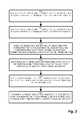
- FIG. 3is a flowchart of the unified switch of FIG. 2 performing loop prevention
- FIG. 4is a unified switch configuration including a roaming user in the mobility domain of FIG. 1 ;
- FIG. 5is a unified switch configuration depicting multi-user load balancing in the configuration of FIG. 4 ;
- FIGS. 6-9are a flowchart of rule selection for loop prevention in the configurations of FIGS. 2 , 4 and 5
- an example configuration of an enterprise mobility networkdefining a mobility domain such as that at a corporate or university campus or site adapted for use with a conventional LAN.
- the unified switchessupport both wireless and wired message traffic, the unified switches perform functions of a wireless switch, in addition to wired routing, and therefore operate as a mobility switch to support roaming from one switch to another by a mobile device.
- the example mobility domain shown in the diagram belowinclude a configuration of network elements, such as switches, access points, and user devices, in an arrangement and number suitable for illustrating the principles of the claimed invention. Other configurations may include other or additional network elements without departing from the substance of the claims.
- the disclosed domainis a split-plane architecture for transporting wireless message traffic and is employed for deploying a plurality of mobility switches in a mobility domain, such that the mobility switches define the data plane of the mobility domain and have a coupling to the mobility controller in the control plane of the mobility domain, in which the data plane performs routing and switching for user data traffic.
- Each unified switchtherefore, includes the functionality of a mobility switch for supporting wireless message traffic as well as L2/L3 wired message traffic.
- wireless message trafficrefers to communications either to or from a mobile device that includes a link between a wireless access point to the mobile device, although the transport path may include wired links such as from the access point to the mobility switch and from the mobility switch to other switches and/or wired network nodes/entities.
- a virtual networkgroups devices for communication independently of the physical connections between them.
- Such a virtual networkis identified by a virtual network identifier, discussed further below.
- the virtual network identifierdenotes collection of devices corresponding to a logical LAN configured such that communication is enabled as if they were part of the same wire (LAN).
- a VLANvirtual LAN
- network nodese.g. switches, mobile devices, stationary endpoints
- Network reconfigurationcan therefore be performed through software instead of physically relocating devices.
- the virtual network identifieris a VLAN identifier as defined by IEEE 802.1Q.
- VLAN membershipcan group devices such that there are multiple routes to a particular destination.
- a mobility switchmay identify multiple ports, corresponding to physical connections and VLAN based paths, that are included in a routing path to a recipient. Since a VLAN is a grouping of devices treated as part of the same LAN, effectively “virtualizing” the physical connections between them, the loop prevention rules disclosed further below manage VLAN membership such that circuitous routes are avoided.
- FIG. 1is a context diagram of a mobility domain suitable for use with the present configuration.
- the mobility domain 100is generally separable into distinct planes of parallel operations that occur in the wireless network defining the mobility domain 100 .
- the mobility domain 100is an enterprise wide network that typically encompasses a particular site of a corporation or institution, and is analogous to an area traditionally served by a conventional LAN (local area network).
- a wireless control plane 102performs radio, AP management, mobility control, user access and authentication through a wireless controller 150 .
- the wireless control plane 102therefore admits users to the mobility domain 100 , and also transports control information in the form of user policies, tunnel management and radio access information, shown by arrows 122 and 132 respectively.
- a typical userinvokes the data plane 104 for performing message traffic transport.
- the data plane 104performs transport and switching of data to and from the user device 110 , using the control information supplied by the control plane 102 to mobility switches 120 and access points 130 using a fabric of network connections 142 .
- the wireless access plane 106bridges the wireless gap from the wireless access point 130 to the user device 110 using a wireless connection 144 , and includes modulation and transmission of the data via an RF channel medium.
- the wireless access plane 106generally provides an overlapping arrangement of coverage areas 134 - 1 . . . 134 - 7 ( 134 generally) to support roaming.
- a network management plane 108provides centralized storage and coordination of items global to the mobility domain, such as applications 112 , user authentication information and other network access control 114 , and an Authentication, Authorization and Accounting (AAA) database DB, 116 .
- a network management system (NMS) 118also provides operator oversight and diagnostic information such as SNMP based inquires.
- Virtual LANs (VLANs) 160provide virtual connections across a plurality of physical and/or wireless connections 142 and 144 to permit roaming from coverage area 134 to coverage area 134 -N, as shown by the mobile device 110 in coverage area 134 - 1 moving to coverage area 134 - 2 as mobile device 110 ′.
- the mobility domain 100therefore provides mobility connectivity for mobile devices 110 through wireless switches 120 and access points 130 , and also performs wired switching in a mobility backplane 140 and for fixed devices, discussed further below.
- FIG. 2is a block diagram of a unified mobility switch configuration illustrating loop prevention.
- a wired switch 120 - 3 and a plurality of mobility switches 120 - 1 . . . 120 - 2define a mobility VLAN 141 interconnecting each of the switches 120 .
- the mobility VLANis part of the mobility backplane 140 .
- the mobility backplane 140may also include switches such as 120 - 3 exclusively for wired L2/L3 transport interconnected with the unified mobility switches 120 - 1 , 120 - 3 .
- Physical connections 142 - 1 . . . 142 - 4 ( 142generally) interconnect the switches 120 and access points 130 - 11 . . . 130 - 12 ( 130 generally) for wired transport.
- the access points 130maintain radio frequency (RF) links 144 with mobile devices 110 - 1 and 110 - 2 , according to WiMax or other 802.11 or similar wireless coupling.
- RFradio frequency
- the mobility domain 100also includes mobility tunnels 124 and access tunnels 126 - 1 . . . 126 - 2 ( 126 generally).
- the mobility tunnels 124operate between mobility switches 120 to support roaming, and the access tunnels 126 operate between mobility switches 120 and access points 130 .
- the tunnels 124 , 126are part of mobility VLANs for maintaining a connection to a mobile device 110 , and represent mappings to multiple physical connections 142 referenced by a port 170 - 11 . . . 170 - 35 ( 170 generally).
- ports 170 corresponding to bothmay be viable for forwarding to a destination such as a mobile device.
- a destinationsuch as a mobile device.
- multiple ports 170may indicate a path leading to a common destination. For example, from mobility switch 120 - 2 , port 170 - 22 maps to a physical connection leading to L2 switch 120 - 3 (via 142 - 4 ). Similarly, port 170 - 21 maps to mobility tunnel 124 , leading to mobility switch 120 - 1 .
- a packet from 110 - 2 to a destination on the mobility VLAN 141 arriving at mobility switch 120 - 2 through access tunnel 126 - 2may be forwarded on either port 170 - 22 or 170 - 21 since both define paths to the intended destination.
- a loop path 128is illustrated by a port selection from mobility switch 120 - 2 attempting to switch a packet from mobility device 110 - 2 to some destination in Mobility VLAN 141 .
- Port 170 - 21is selected to access a VLAN mapped to port 170 - 21 , leading to 120 - 1 .
- port 170 - 12is selected from mobility switch 120 - 1 , as a viable path to the destination, the packet will be forwarded to L2 switch 120 - 3 .
- the physical connection 142 - 4may be seen as a one of the viable paths to the destination if L2 Switch 120 - 3 does not have an entry in its forwarding path for the destination, thus creating the forwarding loop 128 .
- a set of rulesdefines precedence if multiple forwarding paths are available.
- a rulemay state that, in the event of a tunnel port 170 - 21 and a physical port 170 - 22 visible of the same destination, the physical route takes precedence.
- such a rulewould have avoided the looping path 128 started by forwarding on port 170 - 21 , and would instead have routed (forwarded) on port 170 - 22 to L2 switch 120 - 3 , and subsequently to the destination port 170 - 33 at switch 120 - 3 , avoiding ambiguity over multiple potential paths from different mapped ports 170 .
- the loop prevention “rules” as disclosed hereinare a proactive configuration measure preventing looping routing decisions from occurring.
- the potential loop paths disclosed hereinare identified as a configuration matter, not processed as a branch instruction as part of active message (packet) forwarding.
- the loop prevention rulemay be restated as follows:
- the tunnel portis a virtual port and identified by the IP address and the UDP port.
- An administrator or operatorconfigures the physical ports 170 in a VLAN 141 on a Mobility Switch 120 (recall that a unified switch as referred to above includes the switching capability for wireless message traffic implied by mobility switch as well as wired message traffic transport).
- the mobility switches 120 - 1 , 120 - 2establish a mobility tunnel 124 between them through a tunnel management protocol.
- packet loops 128may form if the packet 101 frames (unicast/multicast/broadcast) are forwarded both on physical 142 and tunnel 124 ports 170 in the VLAN 141 as in normal L2 forwarding. Therefore, each of the mobility switches 120 restricts frame forwarding to physical ports 170 - 12 , 170 - 22 only if there is direct connectivity to the VLAN, and employs the tunnel ports 170 - 21 , 170 - 11 for forwarding the frame if there is no physical connectivity in the VLAN 141 .
- mobility switches 120 - 1 and 120 - 2use the wired direct connectivity 142 instead of tunnel ports to forward the traffic of Mobile users in the VLAN 141 .
- FIG. 3is a flowchart of the unified switch of FIG. 2 performing loop prevention.
- the method of loop prevention in a unified split-plane mobility domain 100 as disclosed hereinincludes, at step 200 , identifying a topology of unified switches 120 (mobility switches) for transporting message traffic, in which the message traffic is defined by packets 101 .
- the domain 100identifies a set of links 142 , 124 , 126 between the unified switches 120 for forwarding message traffic packets 101 , such that the links are defined by ports 170 on the unified switches 120 , as depicted at step 201 .
- the links 142 , 124 , 126include hops between the unified switches 120 , each invoked by forwarding on a port 170 corresponding to the link, which may be a physical connection 142 , are a virtual link defined by a port 170 to a mobility tunnel 124 or an access tunnel 126 .
- the forwarding unified switch 120computes, based on a destination (i.e. mobile device 110 or a wired device 111 ), the ports 170 corresponding to the destination, such that each of the links corresponds to a virtual tunnel 124 , 126 or a physical connection 142 and which is accessible via a port 170 on the unified switch 170 , as disclosed at step 202 .
- the unified switch 120 forwarding the packet 101determines when forwarding on a particular port 170 may cause a loop 128 back to the forwarding switch 120 , as depicted at step 203 .
- the unified switch 120identifies, in response to the determined loop 128 , a loop rule 119 , such that the loop rule is indicative of another port 170 for forwarding to the destination 110 , as shown at step 204 .
- the loop rules 119define a configuration similar to a conventional routing table, and may be initially set as an administrative task, may be received from the mobility controller 150 (as propagated “routes”), or propagated via other unified switches 150 . In the example of FIG.
- the existence of both a physical path 142 - 4 and a tunnel 124 leading eventually to a destination 111 , for example, via port 170 - 35triggers the rule specifying use of the port 170 - 22 corresponding to the physical link 142 - 2 .
- the unified switch 120thus forwards the packet on the identified port 170 as determined by the rule 119 , such that the identified port 170 corresponds to a different one 170 - 22 of a tunnel 170 - 21 or a physical port 170 - 22 than the particular port 170 causing the loop, as depicted at step 205 .
- FIG. 4is a unified switch configuration including a roaming user in the mobility domain 100 of FIG. 1 .
- mobility switches 120 - 4 , 120 - 5 and 120 - 6establish mobility tunnels 124 - 1 , 124 - 2 and 124 - 3 between them.
- Mobile devices 110 - 3 and 110 - 4are served by access points 130 - 13 and 130 - 14 respectively, as part of VLAN 143 .
- multiple mobility switches 120 - 4 and 120 - 5are provided for redundancy.
- mMobility device 110 - 4roams into a coverage area supported by access point 130 - 14 , thus causing mobility switch 120 - 6 to seek a mobility tunnel back to “home” VLAN 143 .
- Mobility switch 120 - 6Because of the redundant configuration, multiple paths exist via mobility tunnels 124 - 2 and 124 - 3 , resulting in potential loop 129 , if mobility switch 120 - 6 is permitted to utilize both switches 120 - 4 and 120 - 5 .
- a rule specifying that mobility switch 120 - 6select one mobility switch 120 - 4 or 120 - 5 (or any server of VLAN 143 ) for accessing a particular destination on VLAN 143 .
- Traffic from the roaming user 110 - 4is therefore tunneled to the VLAN 143 through the selected virtual port 170 corresponding to mobility tunnel 124 - 2 or 124 - 3 .
- the rulealso encompasses transition periods where 120 - 4 or 120 - 5 fails and 120 - 6 has to move from one to other to maintain access to VLAN 143 .
- the mobility switches 120thus follow a “break” before “make” principle to prevent loops 129 .
- FIG. 5is a unified switch configuration depicting multi-user load balancing in the configuration of FIG. 4 .
- Mobile device 110 - 4has a path 184 to VLAN 143 via mobility switch 120 - 5 .
- An additional mobility switch 120 - 7 supporting mobile device 110 - 5desires access to VLAN 143 .
- Mobility Switch 120 - 7picks mobility switch 120 - 4 to provide path 182 and is assigned as the designated mobility switch for serving VLAN 143 for all mobile devices connecting to switch 120 - 7 .
- Mobility switch 120 - 6continues to employ mobility switch 120 - 5 via path 184 for load balancing purposes. Additional client mobility switches may thus choose particular mobility switches 120 for load balancing and loop prevention.
- VLAN clientswitches 120 denoted as ‘VLAN client’ switches, rather than on mobile client devices. So all mobile clients on a particular VLAN coming to one remote switch will go to one of the multiple switches 120 acting as a server for that VLAN.
- the configuration of FIG. 5is an extension of the configuration of FIG. 4 .
- the additional unified switch 120 - 7raises the issue of allocating multiple client switches and thus users among available VLAN Server unified switches 120 .
- mobile device 110 - 4 using access points 130 - 14is assigned unified server switch 120 - 5 by client switch 120 - 6
- mobile device 110 - 5 using access point 130 - 15is assigned unified server switch 120 - 4 by client switch 120 - 7 .
- the unified switches 120 and access points 130follow the same rules and thus prevent loops in this case also without hindering load balancing of roamed traffic.
- Mobility switches(unified switches 120 ) which provide physical connectivity for a VLAN 141 , 143 , 145 shall use the ports 170 associated with physical connections 142 for forwarding the traffic in that VLAN. Such ports 170 are treated as VLAN servers for that VLAN.
- the unified switch 120shall use the ports 170 associated with mobility tunnels 124 to forward the packets 101 only when there is no physical connectivity for that VLAN. Such mobility switches 120 are therefore referred to as client switches for that VLAN. Client switches forward the traffic to VLAN servers through the tunnel ports 170 .
- the client mobility switchOn a client switch, if multiple tunnel ports provide connectivity to a VLAN, the client mobility switch shall pick only one of them (based on the load balancing or other selection rule) to forward the traffic in that VLAN. Forwarding the packets 101 on all the tunnel ports 170 may result in a packet loop 129 .
- client switches 120 - 6 , 120 - 7When two or more client switches 120 - 6 , 120 - 7 are using the services of a VLAN 143 , they shall not use the tunnel 124 , 126 ports or physical 142 ports between them for forwarding the traffic in that Remote VLAN 145 . Doing so will result in the packet loop.
- client mobility switches 120shall follow ‘break’ before ‘make” rule while switching over/failing over from one VLAN server to the other.
- FIGS. 6-9are a flowchart of rule selection for loop prevention in the configurations of FIGS. 2 , 4 and 5 .
- the method of loop prevention in a unified split-plane mobility domainincludes, at step 300 , identifying a topology of unified switches 120 for transporting message traffic, in which the message traffic is defined by frames as in a typical Ethernet network. This includes identifying a topology of unified switches 120 in the mobility domain 100 , in which the unified switches 120 are responsive to wired and wireless communication, and each of the unified switches 120 has a set of ports 170 for forwarding packets 101 to other unified switches 120 for transporting the packets of message traffic, as depicted at step 301 .
- the network 141identifies a set of links 142 between the unified switches 120 for forwarding the message traffic packets 101 , in which the links 142 are defined by ports 170 on each of the unified switch, as shown at step 302 .
- the unified switch 120Upon receipt of a packet 101 for forwarding, the unified switch 120 computes, based on a destination 110 , at least one port 170 corresponding to the destination, such that each of the links corresponds to a virtual tunnel 124 , 126 or a physical connection 142 and such that it is accessible via a port 170 on the unified switch 120 , as shown at step 303 .
- Each unified switch 120maintains a topology of links 142 to adjacent unified switches 120 , however need not establish a link 142 with every adjacent unified switch 120 .
- the unified switches 120may establish links according to a mobility switch table that defines switch 120 visibility of other switches 120 in the mobility domain 100 , thus allowing a mesh or hierarchy rather than simply an adjacency topology.
- the unified switch 120determines, from the topology, a path defined by a set of links 142 , which may include one or more links as a tunnel 124 , 126 , as depicted at step 304 .
- the unified switch 120 forwarding the packet 101 to a destination 110determines when forwarding on a particular port 170 causes a loop back to the forwarding switch 120 , as disclosed at step 305 .
- the unified switchcomputes if the path is a looping path 129 , such the looping path results in a packet route back to a previously traversed unified switch 120 , disclosed at step 306 .
- multiple ports 170may offer a path to the same destination 110 via different paths, including a combination of physical links 142 and tunnels 124 , 126 .
- determining a loop 128includes computing a set of links 142 , 124 and 126 that define a loop 128 , such that each of the links is accessible for forwarding via a port 170 in which the loop 128 causes a routing path back to a node (unified switch 120 or other network entity) from which the packet 101 was previously sent, as depicted at step 307 .
- the unified switch 120determines a set of redundant links 142 , 124 or 126 resulting in the potential loop 129 .
- the unified switch 120identifies multiple redundant unified switches 120 interconnected by a mobility tunnel 124 supporting roaming mobile devices 110 corresponding to users, as shown at step 309 .
- the redundant unified switches( 120 - 1 , 2 in FIG. 3 ) define a virtual LAN (VLAN), in which the VLAN has members including at least one tunnel 124 , 126 and each of the tunnels includes a plurality of links corresponding to physical connections 142 , as depicted at step 310 .
- VLANvirtual LAN
- the tunnelsinclude mobility tunnels 124 between unified switches 120 for forwarding to a roaming user, and access tunnels 126 for forwarding to an access point 130 corresponding to a mobile device 110 of the roaming user, as disclosed at step 311 .
- the tunnels 124 and 126include virtual mappings of one or more physical connections 124 , and are mapped to the ports 170 . Thus, a forwarding decision results in forwarding on a particular port 170 , whether by physical 142 or virtual 124 , 126 connection.
- the unified switch 120identifies a physical connection 142 between at least two of the unified switches 120 , indicating the physical path that could result in a loop 129 via a combination of physical 142 and virtual 124 , 126 forwarding decisions.
- the unified switch 120identifies, in response to the determined loop 129 , a loop rule 119 indicative of another port 170 for forwarding to the destination 110 , as depicted at step 313 .
- the selected loop rule 119is dependent on the topology and available ports 170 and links 142 , 124 , 126 for forwarding. If it is determined that the destination 110 is accessible by both a physical connection and a virtual tunnel, as in FIG. 2 , 120 - 1 , 2 , then the identified loop rule 119 directs invocation of the physical connection 142 for forwarding the packet 101 , as shown at step 314 .
- the loop rule 119is selectable from a set of loop rules, and invoking the selected rule includes determining if multiple links provide both a physical connection and a virtual tunnel to a destination, and if so, forwarding the packet 101 on a port 170 corresponding to a physical connection 142 , as disclosed at step 315 . If the check at step 313 determines that the destination is accessible via a plurality of virtual tunnels, each of the virtual tunnels defining a separate path including distinct unified switches, as depicted at step 316 , then the unified switch 120 identifies a virtual tunnel 124 between the distinct unified switches 120 , as in switches 120 - 4 , 5 in FIGS. 4 and 5 (step 317 ).
- the unified switch 120invokes a rule 119 associating one of the distinct unified switches 120 - 4 , 5 for packet forwarding for the destination 110 , as disclosed at step 318 and shown in FIG. 5 .
- a checkis performed, at step 319 , for determining if the multiple links 124 , 126 , 142 correspond to paths to at least two unified switches 120 - 5 , 6 such that the unified switches 120 are connected by a virtual tunnel 124 , and if so, selecting, for each mobile device 110 - 4 , 110 - 5 , a path 182 , 184 corresponding to one of the unified switches 120 - 4 , 5 (respectively) for packets 101 for the mobile device 110 - 4 , 5 , as depicted at step 319 .
- controlselectively passes to step 320 , for identifying a plurality of mobile devices 110 accessible via the same set of distinct unified switches 120 , as in the scenario depicted in FIG. 5 illustrating a further extension of the scenario of FIG. 4 .
- the unified switch 120invokes a rule 119 apportioning unified switches 120 acting as VLAN servers among other unified switches 120 acting as VLAN clients for load balancing the mobile devices 110 among the distinct unified switches 120 -N, as shown at step 321 .
- the VLAN client unified switches 120select one of the server unified switches 120 so that the mobile devices 110 are apportioned among the available paths. This includes, at step 322 , determining if a plurality of unified switches 120 in a VLAN are connected by at least one of physical connections or virtual tunnels.
- the unified switch 120restricts forwarding on the connections in the VLAN for packets associated with a roaming mobile device 110 - 4 , 5 as depicted at step 323 to avoid forwarding on the loop path 129 .
- the loop rulesfurther include determining if an overload or failure condition mandates failover from one of the unified switches 120 to another unified switch 120 in a common VLAN, as depicted at step 324 , and terminating existing connections and associations for a failed unified switch 120 before initiating associations to the failover unified switch 120 , as shown at step 325 .
- the unified switch 120Based on the application of one or more of the rules 319 in step 314 , 316 and 320 , the unified switch 120 implements a routing (forwarding) decision by identifying a port 170 corresponding to the computed looping path 129 , as depicted at step 326 , and forwarding the packet on another port 170 that avoids the loop path 129 , as disclosed at step 327 .
- forwarding logicmakes the right decision because the control layer manages VLAN membership of the physical or logical port. So the forwarding decision is the result of normal L2 switching when VLAN membership is implemented according to the loop prevention rules.
- Control message handlingdetects potential loops and enforces the rules by managing VLAN memberships of the tunnel and physical ports.
- the rulestherefore direct port VLAN membership management, and need not interfere with routing decisions, which could adversely affect throughput and performance, because the forwarding decisions that avoid loop follow from setting VLAN membership accordingly.
- One particular feature of managing the VLAN membershipsis that the forwarding logic remains standard and efficient and can be implemented by existing ASIC forwarding logic blocks. Conventional approaches, such as by modifying the forwarding logic may not be as efficient and may introduce non-standard behavior.
- the unified switch 120thus forwards the packet 101 on the identified port 170 , such that the identified port 170 corresponds to a different one of a tunnel 124 , 126 or a physical port 170 and path 142 than the particular port 170 determined to cause the loop 129 .
- Alternate implementationsmay incorporate other and/or additional rules for identifying and forwarding around looping paths, thus identifying alternate configurations for selecting from multiple ports associated with multiple virtual and/or physical paths triggered for the same routing destination.
- the forwarding logic employing the VLAN membership for avoiding loopsis directed to L2 forwarding and switching, in contrast to L3 routing, as is known in the art. Alternate configurations may apply similar operation on the scale of an L3 routing loop without deviating from the scope of the claimed approach.
- the programs and methods for loop prevention in a unified split-plane mobility domain as defined hereinare deliverable to a user processing and rendering device in many forms, including but not limited to a) a non-transitory computer readable storage medium, b) information permanently stored on non-writeable storage media such as ROM devices, c) information alterably stored on writeable storage media such as floppy disks, magnetic tapes, CDs, RAM devices, and other magnetic and optical media, or d) information conveyed to a computer through communication media, as in an electronic network such as the Internet or telephone modem lines.
- the operations and methodsmay be implemented in a software executable object or as a set of encoded instructions for execution by a processor responsive to the instructions.
- ASICsApplication Specific Integrated Circuits
- FPGAsField Programmable Gate Arrays
- state machinescontrollers or other hardware components or devices, or a combination of hardware, software, and firmware components.
Landscapes
- Engineering & Computer Science (AREA)
- Computer Networks & Wireless Communication (AREA)
- Signal Processing (AREA)
- Computer Security & Cryptography (AREA)
- Mobile Radio Communication Systems (AREA)
Abstract
Description
Claims (20)
Priority Applications (1)
| Application Number | Priority Date | Filing Date | Title |
|---|---|---|---|
| US12/772,299US8300614B2 (en) | 2009-05-14 | 2010-05-03 | Preventing packet loops in unified networks |
Applications Claiming Priority (2)
| Application Number | Priority Date | Filing Date | Title |
|---|---|---|---|
| US17826309P | 2009-05-14 | 2009-05-14 | |
| US12/772,299US8300614B2 (en) | 2009-05-14 | 2010-05-03 | Preventing packet loops in unified networks |
Publications (2)
| Publication Number | Publication Date |
|---|---|
| US20100290385A1 US20100290385A1 (en) | 2010-11-18 |
| US8300614B2true US8300614B2 (en) | 2012-10-30 |
Family
ID=43068444
Family Applications (1)
| Application Number | Title | Priority Date | Filing Date |
|---|---|---|---|
| US12/772,299Active2031-05-12US8300614B2 (en) | 2009-05-14 | 2010-05-03 | Preventing packet loops in unified networks |
Country Status (1)
| Country | Link |
|---|---|
| US (1) | US8300614B2 (en) |
Cited By (18)
| Publication number | Priority date | Publication date | Assignee | Title |
|---|---|---|---|---|
| US20100290465A1 (en)* | 2009-05-14 | 2010-11-18 | Avaya Inc. | Methods, apparatus and computer readable medium for seamless internet protocol multicast connectivity in unified networks |
| US8448238B1 (en) | 2013-01-23 | 2013-05-21 | Sideband Networks, Inc. | Network security as a service using virtual secure channels |
| US9372347B1 (en) | 2015-02-09 | 2016-06-21 | Microsoft Technology Licensing, Llc | Display system |
| US9414417B2 (en) | 2014-08-07 | 2016-08-09 | Microsoft Technology Licensing, Llc | Propagating communication awareness over a cellular network |
| US9423360B1 (en) | 2015-02-09 | 2016-08-23 | Microsoft Technology Licensing, Llc | Optical components |
| US9429692B1 (en) | 2015-02-09 | 2016-08-30 | Microsoft Technology Licensing, Llc | Optical components |
| US9513480B2 (en) | 2015-02-09 | 2016-12-06 | Microsoft Technology Licensing, Llc | Waveguide |
| US9535253B2 (en) | 2015-02-09 | 2017-01-03 | Microsoft Technology Licensing, Llc | Display system |
| CN106850382A (en)* | 2016-12-05 | 2017-06-13 | 北京神州绿盟信息安全科技股份有限公司 | A kind of flow lead method and device |
| US9787576B2 (en) | 2014-07-31 | 2017-10-10 | Microsoft Technology Licensing, Llc | Propagating routing awareness for autonomous networks |
| US9827209B2 (en) | 2015-02-09 | 2017-11-28 | Microsoft Technology Licensing, Llc | Display system |
| US10018844B2 (en) | 2015-02-09 | 2018-07-10 | Microsoft Technology Licensing, Llc | Wearable image display system |
| US10254942B2 (en) | 2014-07-31 | 2019-04-09 | Microsoft Technology Licensing, Llc | Adaptive sizing and positioning of application windows |
| US10317677B2 (en) | 2015-02-09 | 2019-06-11 | Microsoft Technology Licensing, Llc | Display system |
| US10592080B2 (en) | 2014-07-31 | 2020-03-17 | Microsoft Technology Licensing, Llc | Assisted presentation of application windows |
| US10678412B2 (en) | 2014-07-31 | 2020-06-09 | Microsoft Technology Licensing, Llc | Dynamic joint dividers for application windows |
| US11086216B2 (en) | 2015-02-09 | 2021-08-10 | Microsoft Technology Licensing, Llc | Generating electronic components |
| US11929907B2 (en) | 2022-03-08 | 2024-03-12 | T-Mobile Usa, Inc. | Endpoint assisted selection of routing paths over multiple networks |
Families Citing this family (22)
| Publication number | Priority date | Publication date | Assignee | Title |
|---|---|---|---|---|
| US7965719B2 (en)* | 2002-12-11 | 2011-06-21 | Broadcom Corporation | Media exchange network supporting multiple broadband network and service provider infrastructures |
| EP2675119B1 (en)* | 2011-02-07 | 2019-03-27 | Nec Corporation | Communication system, control device, communication node, and communication method |
| US8971289B2 (en)* | 2011-05-24 | 2015-03-03 | Cisco Technology, Inc. | Maintaining point of presence for clients roaming within a layer 2 domain |
| US20160028589A1 (en)* | 2013-03-15 | 2016-01-28 | Hewlett-Packard Development Company, L.P. | Data loop detection |
| US9548960B2 (en) | 2013-10-06 | 2017-01-17 | Mellanox Technologies Ltd. | Simplified packet routing |
| US9729473B2 (en) | 2014-06-23 | 2017-08-08 | Mellanox Technologies, Ltd. | Network high availability using temporary re-routing |
| US9806994B2 (en) | 2014-06-24 | 2017-10-31 | Mellanox Technologies, Ltd. | Routing via multiple paths with efficient traffic distribution |
| US9894005B2 (en) | 2015-03-31 | 2018-02-13 | Mellanox Technologies, Ltd. | Adaptive routing controlled by source node |
| US9973435B2 (en)* | 2015-12-16 | 2018-05-15 | Mellanox Technologies Tlv Ltd. | Loopback-free adaptive routing |
| US10819621B2 (en) | 2016-02-23 | 2020-10-27 | Mellanox Technologies Tlv Ltd. | Unicast forwarding of adaptive-routing notifications |
| US10178029B2 (en) | 2016-05-11 | 2019-01-08 | Mellanox Technologies Tlv Ltd. | Forwarding of adaptive routing notifications |
| US10200294B2 (en) | 2016-12-22 | 2019-02-05 | Mellanox Technologies Tlv Ltd. | Adaptive routing based on flow-control credits |
| US10644995B2 (en) | 2018-02-14 | 2020-05-05 | Mellanox Technologies Tlv Ltd. | Adaptive routing in a box |
| US11005724B1 (en) | 2019-01-06 | 2021-05-11 | Mellanox Technologies, Ltd. | Network topology having minimal number of long connections among groups of network elements |
| US11575594B2 (en) | 2020-09-10 | 2023-02-07 | Mellanox Technologies, Ltd. | Deadlock-free rerouting for resolving local link failures using detour paths |
| US11411911B2 (en) | 2020-10-26 | 2022-08-09 | Mellanox Technologies, Ltd. | Routing across multiple subnetworks using address mapping |
| US11870682B2 (en) | 2021-06-22 | 2024-01-09 | Mellanox Technologies, Ltd. | Deadlock-free local rerouting for handling multiple local link failures in hierarchical network topologies |
| CN116016200A (en)* | 2021-10-22 | 2023-04-25 | 中兴通讯股份有限公司 | Network loop analysis method, electronic device, and computer-readable storage medium |
| US11765103B2 (en) | 2021-12-01 | 2023-09-19 | Mellanox Technologies, Ltd. | Large-scale network with high port utilization |
| US12155563B2 (en) | 2022-09-05 | 2024-11-26 | Mellanox Technologies, Ltd. | Flexible per-flow multipath managed by sender-side network adapter |
| US12328251B2 (en) | 2022-09-08 | 2025-06-10 | Mellano Technologies, Ltd. | Marking of RDMA-over-converged-ethernet (RoCE) traffic eligible for adaptive routing |
| US20250112855A1 (en)* | 2023-10-03 | 2025-04-03 | Hewlett Packard Enterprise Development Lp | Identifying loop-origination points in an overlay network |
Citations (9)
| Publication number | Priority date | Publication date | Assignee | Title |
|---|---|---|---|---|
| US4797589A (en)* | 1986-02-03 | 1989-01-10 | Arthur A. Collins, Inc. | Dynamically reconfigurable time-space-time digital switch and network |
| US6192054B1 (en)* | 1996-08-08 | 2001-02-20 | Gadzoox Networks, Inc. | Accelerated fibre channel hub and protocol |
| US6304639B1 (en)* | 1995-07-14 | 2001-10-16 | Telefonaktiebolaget Lm Ericsson | System and methods for controlling virtual paths within a network based on entropy rate function |
| US20020057657A1 (en)* | 1998-12-11 | 2002-05-16 | Thomas F. La Porta | Packet tunneling optimization to wireless devices accessing packet-based wired networks |
| US6597663B1 (en)* | 1997-03-03 | 2003-07-22 | Cisco Technology, Inc. | Technique for handling forwarding transients with link state routing protocol |
| US20060256775A1 (en)* | 2005-05-16 | 2006-11-16 | Mcrae Matthew | Upstream data rate estimation |
| US20070036178A1 (en)* | 2005-02-02 | 2007-02-15 | Susan Hares | Layer 2 virtual switching environment |
| US7239618B1 (en)* | 1998-12-11 | 2007-07-03 | Lucent Technologies Inc. | Single phase local mobility scheme for wireless access to packet-based networks |
| US7869347B2 (en)* | 2008-06-19 | 2011-01-11 | International Business Machines Corporation | Futile neighbor state loop prevention in high availability networks |
- 2010
- 2010-05-03USUS12/772,299patent/US8300614B2/enactiveActive
Patent Citations (12)
| Publication number | Priority date | Publication date | Assignee | Title |
|---|---|---|---|---|
| US4797589A (en)* | 1986-02-03 | 1989-01-10 | Arthur A. Collins, Inc. | Dynamically reconfigurable time-space-time digital switch and network |
| US4797589C1 (en)* | 1986-02-03 | 2002-09-10 | Collins Mary | Dynamically reconfigurable time-space-time digital switch and network |
| US6304639B1 (en)* | 1995-07-14 | 2001-10-16 | Telefonaktiebolaget Lm Ericsson | System and methods for controlling virtual paths within a network based on entropy rate function |
| US6192054B1 (en)* | 1996-08-08 | 2001-02-20 | Gadzoox Networks, Inc. | Accelerated fibre channel hub and protocol |
| US6597663B1 (en)* | 1997-03-03 | 2003-07-22 | Cisco Technology, Inc. | Technique for handling forwarding transients with link state routing protocol |
| US20020057657A1 (en)* | 1998-12-11 | 2002-05-16 | Thomas F. La Porta | Packet tunneling optimization to wireless devices accessing packet-based wired networks |
| US6496505B2 (en)* | 1998-12-11 | 2002-12-17 | Lucent Technologies Inc. | Packet tunneling optimization to wireless devices accessing packet-based wired networks |
| US7239618B1 (en)* | 1998-12-11 | 2007-07-03 | Lucent Technologies Inc. | Single phase local mobility scheme for wireless access to packet-based networks |
| US20070036178A1 (en)* | 2005-02-02 | 2007-02-15 | Susan Hares | Layer 2 virtual switching environment |
| US20060256775A1 (en)* | 2005-05-16 | 2006-11-16 | Mcrae Matthew | Upstream data rate estimation |
| US7924815B2 (en)* | 2005-05-16 | 2011-04-12 | Cisco Technology, Inc. | Upstream data rate estimation |
| US7869347B2 (en)* | 2008-06-19 | 2011-01-11 | International Business Machines Corporation | Futile neighbor state loop prevention in high availability networks |
Cited By (20)
| Publication number | Priority date | Publication date | Assignee | Title |
|---|---|---|---|---|
| US8942167B2 (en)* | 2009-05-14 | 2015-01-27 | Avaya Inc. | Methods, apparatus and computer readable medium for seamless internet protocol multicast connectivity in unified networks |
| US20100290465A1 (en)* | 2009-05-14 | 2010-11-18 | Avaya Inc. | Methods, apparatus and computer readable medium for seamless internet protocol multicast connectivity in unified networks |
| US8448238B1 (en) | 2013-01-23 | 2013-05-21 | Sideband Networks, Inc. | Network security as a service using virtual secure channels |
| US9787576B2 (en) | 2014-07-31 | 2017-10-10 | Microsoft Technology Licensing, Llc | Propagating routing awareness for autonomous networks |
| US10678412B2 (en) | 2014-07-31 | 2020-06-09 | Microsoft Technology Licensing, Llc | Dynamic joint dividers for application windows |
| US10592080B2 (en) | 2014-07-31 | 2020-03-17 | Microsoft Technology Licensing, Llc | Assisted presentation of application windows |
| US10254942B2 (en) | 2014-07-31 | 2019-04-09 | Microsoft Technology Licensing, Llc | Adaptive sizing and positioning of application windows |
| US9414417B2 (en) | 2014-08-07 | 2016-08-09 | Microsoft Technology Licensing, Llc | Propagating communication awareness over a cellular network |
| US9860321B2 (en) | 2014-08-07 | 2018-01-02 | Microsoft Technology Licensing, Llc | Propagating communication awareness over a cellular network |
| US9423360B1 (en) | 2015-02-09 | 2016-08-23 | Microsoft Technology Licensing, Llc | Optical components |
| US9827209B2 (en) | 2015-02-09 | 2017-11-28 | Microsoft Technology Licensing, Llc | Display system |
| US9535253B2 (en) | 2015-02-09 | 2017-01-03 | Microsoft Technology Licensing, Llc | Display system |
| US10018844B2 (en) | 2015-02-09 | 2018-07-10 | Microsoft Technology Licensing, Llc | Wearable image display system |
| US9513480B2 (en) | 2015-02-09 | 2016-12-06 | Microsoft Technology Licensing, Llc | Waveguide |
| US10317677B2 (en) | 2015-02-09 | 2019-06-11 | Microsoft Technology Licensing, Llc | Display system |
| US9429692B1 (en) | 2015-02-09 | 2016-08-30 | Microsoft Technology Licensing, Llc | Optical components |
| US9372347B1 (en) | 2015-02-09 | 2016-06-21 | Microsoft Technology Licensing, Llc | Display system |
| US11086216B2 (en) | 2015-02-09 | 2021-08-10 | Microsoft Technology Licensing, Llc | Generating electronic components |
| CN106850382A (en)* | 2016-12-05 | 2017-06-13 | 北京神州绿盟信息安全科技股份有限公司 | A kind of flow lead method and device |
| US11929907B2 (en) | 2022-03-08 | 2024-03-12 | T-Mobile Usa, Inc. | Endpoint assisted selection of routing paths over multiple networks |
Also Published As
| Publication number | Publication date |
|---|---|
| US20100290385A1 (en) | 2010-11-18 |
Similar Documents
| Publication | Publication Date | Title |
|---|---|---|
| US8300614B2 (en) | Preventing packet loops in unified networks | |
| US12106160B2 (en) | First hop gateway redundancy in a network computing environment | |
| US10742557B1 (en) | Extending scalable policy management to supporting network devices | |
| US11777783B2 (en) | Network slicing with smart contracts | |
| US20210105669A1 (en) | Service delivery to a roaming user equipment using a software-defined networking (sdn) controller | |
| US8867507B2 (en) | Split-plane wireless network architecture | |
| EP2817926B1 (en) | Delegate forwarding and address resolution in fragmented network | |
| US9167501B2 (en) | Implementing a 3G packet core in a cloud computer with openflow data and control planes | |
| CA2847103C (en) | Implementing a 3g packet core in a cloud computer with openflow data and control planes | |
| CN106576117B (en) | Ultra-high-speed mobile network based on layer 2 switching | |
| US9407493B2 (en) | System and apparatus for router advertisement options for configuring networks to support multi-homed next hop routes | |
| US12375321B2 (en) | Method and system for ethernet virtual private network (EVPN) split-horizon filtering | |
| US12317179B2 (en) | Dynamic access network selection based on application orchestration information in an edge cloud system | |
| CN114980243B (en) | A data forwarding method, device and storage medium | |
| EP3716529A1 (en) | Tunneling inter-domain stateless internet protocol multicast packets | |
| WO2022057810A1 (en) | Service packet forwarding method, sr policy sending method, device, and system | |
| GB2485025A (en) | Providing Routed Split Multi-Link Trunking (RSMLT) for Wireless Local Area Network (WLAN) tunnels | |
| CN114450671A (en) | Method and system for cache management in a network device | |
| Amamou et al. | A trill-based multi-tenant data center network | |
| CN116938809B (en) | Network switch, method for network switching, and computer storage medium | |
| US12432092B2 (en) | Dynamic assignments of tunnels to broadcast groups | |
| US20240364635A1 (en) | Dynamic distribution of client devices in gateway cluster | |
| WO2023138351A1 (en) | Traffic forwarding method, packet sending method, message sending method, and apparatus |
Legal Events
| Date | Code | Title | Description |
|---|---|---|---|
| AS | Assignment | Owner name:AVAYA INC., NEW JERSEY Free format text:ASSIGNMENT OF ASSIGNORS INTEREST;ASSIGNORS:ANKAIAH, SHASHI H.;ATREYA, VIVEK;KARUNAKARAN, KUMARA DAS;AND OTHERS;SIGNING DATES FROM 20100430 TO 20100503;REEL/FRAME:024323/0046 | |
| AS | Assignment | Owner name:BANK OF NEW YORK MELLON TRUST, NA, AS NOTES COLLATERAL AGENT, THE, PENNSYLVANIA Free format text:SECURITY AGREEMENT;ASSIGNOR:AVAYA INC., A DELAWARE CORPORATION;REEL/FRAME:025863/0535 Effective date:20110211 Owner name:BANK OF NEW YORK MELLON TRUST, NA, AS NOTES COLLAT Free format text:SECURITY AGREEMENT;ASSIGNOR:AVAYA INC., A DELAWARE CORPORATION;REEL/FRAME:025863/0535 Effective date:20110211 | |
| FEPP | Fee payment procedure | Free format text:PAYOR NUMBER ASSIGNED (ORIGINAL EVENT CODE: ASPN); ENTITY STATUS OF PATENT OWNER: LARGE ENTITY | |
| STCF | Information on status: patent grant | Free format text:PATENTED CASE | |
| AS | Assignment | Owner name:THE BANK OF NEW YORK MELLON TRUST COMPANY, N.A., PENNSYLVANIA Free format text:SECURITY AGREEMENT;ASSIGNOR:AVAYA, INC.;REEL/FRAME:029608/0256 Effective date:20121221 Owner name:THE BANK OF NEW YORK MELLON TRUST COMPANY, N.A., P Free format text:SECURITY AGREEMENT;ASSIGNOR:AVAYA, INC.;REEL/FRAME:029608/0256 Effective date:20121221 | |
| AS | Assignment | Owner name:BANK OF NEW YORK MELLON TRUST COMPANY, N.A., THE, PENNSYLVANIA Free format text:SECURITY AGREEMENT;ASSIGNOR:AVAYA, INC.;REEL/FRAME:030083/0639 Effective date:20130307 Owner name:BANK OF NEW YORK MELLON TRUST COMPANY, N.A., THE, Free format text:SECURITY AGREEMENT;ASSIGNOR:AVAYA, INC.;REEL/FRAME:030083/0639 Effective date:20130307 | |
| FPAY | Fee payment | Year of fee payment:4 | |
| AS | Assignment | Owner name:CITIBANK, N.A., AS ADMINISTRATIVE AGENT, NEW YORK Free format text:SECURITY INTEREST;ASSIGNORS:AVAYA INC.;AVAYA INTEGRATED CABINET SOLUTIONS INC.;OCTEL COMMUNICATIONS CORPORATION;AND OTHERS;REEL/FRAME:041576/0001 Effective date:20170124 | |
| AS | Assignment | Owner name:OCTEL COMMUNICATIONS LLC (FORMERLY KNOWN AS OCTEL COMMUNICATIONS CORPORATION), CALIFORNIA Free format text:BANKRUPTCY COURT ORDER RELEASING ALL LIENS INCLUDING THE SECURITY INTEREST RECORDED AT REEL/FRAME 041576/0001;ASSIGNOR:CITIBANK, N.A.;REEL/FRAME:044893/0531 Effective date:20171128 Owner name:AVAYA INTEGRATED CABINET SOLUTIONS INC., CALIFORNIA Free format text:BANKRUPTCY COURT ORDER RELEASING ALL LIENS INCLUDING THE SECURITY INTEREST RECORDED AT REEL/FRAME 041576/0001;ASSIGNOR:CITIBANK, N.A.;REEL/FRAME:044893/0531 Effective date:20171128 Owner name:AVAYA INC., CALIFORNIA Free format text:BANKRUPTCY COURT ORDER RELEASING ALL LIENS INCLUDING THE SECURITY INTEREST RECORDED AT REEL/FRAME 025863/0535;ASSIGNOR:THE BANK OF NEW YORK MELLON TRUST, NA;REEL/FRAME:044892/0001 Effective date:20171128 Owner name:AVAYA INC., CALIFORNIA Free format text:BANKRUPTCY COURT ORDER RELEASING ALL LIENS INCLUDING THE SECURITY INTEREST RECORDED AT REEL/FRAME 029608/0256;ASSIGNOR:THE BANK OF NEW YORK MELLON TRUST COMPANY, N.A.;REEL/FRAME:044891/0801 Effective date:20171128 Owner name:VPNET TECHNOLOGIES, INC., CALIFORNIA Free format text:BANKRUPTCY COURT ORDER RELEASING ALL LIENS INCLUDING THE SECURITY INTEREST RECORDED AT REEL/FRAME 041576/0001;ASSIGNOR:CITIBANK, N.A.;REEL/FRAME:044893/0531 Effective date:20171128 Owner name:OCTEL COMMUNICATIONS LLC (FORMERLY KNOWN AS OCTEL Free format text:BANKRUPTCY COURT ORDER RELEASING ALL LIENS INCLUDING THE SECURITY INTEREST RECORDED AT REEL/FRAME 041576/0001;ASSIGNOR:CITIBANK, N.A.;REEL/FRAME:044893/0531 Effective date:20171128 Owner name:AVAYA INTEGRATED CABINET SOLUTIONS INC., CALIFORNI Free format text:BANKRUPTCY COURT ORDER RELEASING ALL LIENS INCLUDING THE SECURITY INTEREST RECORDED AT REEL/FRAME 041576/0001;ASSIGNOR:CITIBANK, N.A.;REEL/FRAME:044893/0531 Effective date:20171128 Owner name:AVAYA INC., CALIFORNIA Free format text:BANKRUPTCY COURT ORDER RELEASING ALL LIENS INCLUDING THE SECURITY INTEREST RECORDED AT REEL/FRAME 041576/0001;ASSIGNOR:CITIBANK, N.A.;REEL/FRAME:044893/0531 Effective date:20171128 Owner name:AVAYA INC., CALIFORNIA Free format text:BANKRUPTCY COURT ORDER RELEASING ALL LIENS INCLUDING THE SECURITY INTEREST RECORDED AT REEL/FRAME 030083/0639;ASSIGNOR:THE BANK OF NEW YORK MELLON TRUST COMPANY, N.A.;REEL/FRAME:045012/0666 Effective date:20171128 | |
| AS | Assignment | Owner name:GOLDMAN SACHS BANK USA, AS COLLATERAL AGENT, NEW YORK Free format text:SECURITY INTEREST;ASSIGNORS:AVAYA INC.;AVAYA INTEGRATED CABINET SOLUTIONS LLC;OCTEL COMMUNICATIONS LLC;AND OTHERS;REEL/FRAME:045034/0001 Effective date:20171215 Owner name:GOLDMAN SACHS BANK USA, AS COLLATERAL AGENT, NEW Y Free format text:SECURITY INTEREST;ASSIGNORS:AVAYA INC.;AVAYA INTEGRATED CABINET SOLUTIONS LLC;OCTEL COMMUNICATIONS LLC;AND OTHERS;REEL/FRAME:045034/0001 Effective date:20171215 | |
| AS | Assignment | Owner name:CITIBANK, N.A., AS COLLATERAL AGENT, NEW YORK Free format text:SECURITY INTEREST;ASSIGNORS:AVAYA INC.;AVAYA INTEGRATED CABINET SOLUTIONS LLC;OCTEL COMMUNICATIONS LLC;AND OTHERS;REEL/FRAME:045124/0026 Effective date:20171215 | |
| MAFP | Maintenance fee payment | Free format text:PAYMENT OF MAINTENANCE FEE, 8TH YEAR, LARGE ENTITY (ORIGINAL EVENT CODE: M1552); ENTITY STATUS OF PATENT OWNER: LARGE ENTITY Year of fee payment:8 | |
| AS | Assignment | Owner name:WILMINGTON TRUST, NATIONAL ASSOCIATION, MINNESOTA Free format text:SECURITY INTEREST;ASSIGNORS:AVAYA INC.;AVAYA MANAGEMENT L.P.;INTELLISIST, INC.;AND OTHERS;REEL/FRAME:053955/0436 Effective date:20200925 | |
| AS | Assignment | Owner name:WILMINGTON TRUST, NATIONAL ASSOCIATION, AS COLLATERAL AGENT, DELAWARE Free format text:INTELLECTUAL PROPERTY SECURITY AGREEMENT;ASSIGNORS:AVAYA INC.;INTELLISIST, INC.;AVAYA MANAGEMENT L.P.;AND OTHERS;REEL/FRAME:061087/0386 Effective date:20220712 | |
| AS | Assignment | Owner name:AVAYA INTEGRATED CABINET SOLUTIONS LLC, NEW JERSEY Free format text:RELEASE OF SECURITY INTEREST IN PATENTS AT REEL 45124/FRAME 0026;ASSIGNOR:CITIBANK, N.A., AS COLLATERAL AGENT;REEL/FRAME:063457/0001 Effective date:20230403 Owner name:AVAYA MANAGEMENT L.P., NEW JERSEY Free format text:RELEASE OF SECURITY INTEREST IN PATENTS AT REEL 45124/FRAME 0026;ASSIGNOR:CITIBANK, N.A., AS COLLATERAL AGENT;REEL/FRAME:063457/0001 Effective date:20230403 Owner name:AVAYA INC., NEW JERSEY Free format text:RELEASE OF SECURITY INTEREST IN PATENTS AT REEL 45124/FRAME 0026;ASSIGNOR:CITIBANK, N.A., AS COLLATERAL AGENT;REEL/FRAME:063457/0001 Effective date:20230403 Owner name:AVAYA HOLDINGS CORP., NEW JERSEY Free format text:RELEASE OF SECURITY INTEREST IN PATENTS AT REEL 45124/FRAME 0026;ASSIGNOR:CITIBANK, N.A., AS COLLATERAL AGENT;REEL/FRAME:063457/0001 Effective date:20230403 | |
| AS | Assignment | Owner name:WILMINGTON SAVINGS FUND SOCIETY, FSB (COLLATERAL AGENT), DELAWARE Free format text:INTELLECTUAL PROPERTY SECURITY AGREEMENT;ASSIGNORS:AVAYA MANAGEMENT L.P.;AVAYA INC.;INTELLISIST, INC.;AND OTHERS;REEL/FRAME:063742/0001 Effective date:20230501 | |
| AS | Assignment | Owner name:CITIBANK, N.A., AS COLLATERAL AGENT, NEW YORK Free format text:INTELLECTUAL PROPERTY SECURITY AGREEMENT;ASSIGNORS:AVAYA INC.;AVAYA MANAGEMENT L.P.;INTELLISIST, INC.;REEL/FRAME:063542/0662 Effective date:20230501 | |
| AS | Assignment | Owner name:AVAYA MANAGEMENT L.P., NEW JERSEY Free format text:RELEASE OF SECURITY INTEREST IN PATENTS (REEL/FRAME 045034/0001);ASSIGNOR:GOLDMAN SACHS BANK USA., AS COLLATERAL AGENT;REEL/FRAME:063779/0622 Effective date:20230501 Owner name:CAAS TECHNOLOGIES, LLC, NEW JERSEY Free format text:RELEASE OF SECURITY INTEREST IN PATENTS (REEL/FRAME 045034/0001);ASSIGNOR:GOLDMAN SACHS BANK USA., AS COLLATERAL AGENT;REEL/FRAME:063779/0622 Effective date:20230501 Owner name:HYPERQUALITY II, LLC, NEW JERSEY Free format text:RELEASE OF SECURITY INTEREST IN PATENTS (REEL/FRAME 045034/0001);ASSIGNOR:GOLDMAN SACHS BANK USA., AS COLLATERAL AGENT;REEL/FRAME:063779/0622 Effective date:20230501 Owner name:HYPERQUALITY, INC., NEW JERSEY Free format text:RELEASE OF SECURITY INTEREST IN PATENTS (REEL/FRAME 045034/0001);ASSIGNOR:GOLDMAN SACHS BANK USA., AS COLLATERAL AGENT;REEL/FRAME:063779/0622 Effective date:20230501 Owner name:ZANG, INC. (FORMER NAME OF AVAYA CLOUD INC.), NEW JERSEY Free format text:RELEASE OF SECURITY INTEREST IN PATENTS (REEL/FRAME 045034/0001);ASSIGNOR:GOLDMAN SACHS BANK USA., AS COLLATERAL AGENT;REEL/FRAME:063779/0622 Effective date:20230501 Owner name:VPNET TECHNOLOGIES, INC., NEW JERSEY Free format text:RELEASE OF SECURITY INTEREST IN PATENTS (REEL/FRAME 045034/0001);ASSIGNOR:GOLDMAN SACHS BANK USA., AS COLLATERAL AGENT;REEL/FRAME:063779/0622 Effective date:20230501 Owner name:OCTEL COMMUNICATIONS LLC, NEW JERSEY Free format text:RELEASE OF SECURITY INTEREST IN PATENTS (REEL/FRAME 045034/0001);ASSIGNOR:GOLDMAN SACHS BANK USA., AS COLLATERAL AGENT;REEL/FRAME:063779/0622 Effective date:20230501 Owner name:AVAYA INTEGRATED CABINET SOLUTIONS LLC, NEW JERSEY Free format text:RELEASE OF SECURITY INTEREST IN PATENTS (REEL/FRAME 045034/0001);ASSIGNOR:GOLDMAN SACHS BANK USA., AS COLLATERAL AGENT;REEL/FRAME:063779/0622 Effective date:20230501 Owner name:INTELLISIST, INC., NEW JERSEY Free format text:RELEASE OF SECURITY INTEREST IN PATENTS (REEL/FRAME 045034/0001);ASSIGNOR:GOLDMAN SACHS BANK USA., AS COLLATERAL AGENT;REEL/FRAME:063779/0622 Effective date:20230501 Owner name:AVAYA INC., NEW JERSEY Free format text:RELEASE OF SECURITY INTEREST IN PATENTS (REEL/FRAME 045034/0001);ASSIGNOR:GOLDMAN SACHS BANK USA., AS COLLATERAL AGENT;REEL/FRAME:063779/0622 Effective date:20230501 Owner name:AVAYA INTEGRATED CABINET SOLUTIONS LLC, NEW JERSEY Free format text:RELEASE OF SECURITY INTEREST IN PATENTS (REEL/FRAME 53955/0436);ASSIGNOR:WILMINGTON TRUST, NATIONAL ASSOCIATION, AS NOTES COLLATERAL AGENT;REEL/FRAME:063705/0023 Effective date:20230501 Owner name:INTELLISIST, INC., NEW JERSEY Free format text:RELEASE OF SECURITY INTEREST IN PATENTS (REEL/FRAME 53955/0436);ASSIGNOR:WILMINGTON TRUST, NATIONAL ASSOCIATION, AS NOTES COLLATERAL AGENT;REEL/FRAME:063705/0023 Effective date:20230501 Owner name:AVAYA INC., NEW JERSEY Free format text:RELEASE OF SECURITY INTEREST IN PATENTS (REEL/FRAME 53955/0436);ASSIGNOR:WILMINGTON TRUST, NATIONAL ASSOCIATION, AS NOTES COLLATERAL AGENT;REEL/FRAME:063705/0023 Effective date:20230501 Owner name:AVAYA MANAGEMENT L.P., NEW JERSEY Free format text:RELEASE OF SECURITY INTEREST IN PATENTS (REEL/FRAME 53955/0436);ASSIGNOR:WILMINGTON TRUST, NATIONAL ASSOCIATION, AS NOTES COLLATERAL AGENT;REEL/FRAME:063705/0023 Effective date:20230501 Owner name:AVAYA INTEGRATED CABINET SOLUTIONS LLC, NEW JERSEY Free format text:RELEASE OF SECURITY INTEREST IN PATENTS (REEL/FRAME 61087/0386);ASSIGNOR:WILMINGTON TRUST, NATIONAL ASSOCIATION, AS NOTES COLLATERAL AGENT;REEL/FRAME:063690/0359 Effective date:20230501 Owner name:INTELLISIST, INC., NEW JERSEY Free format text:RELEASE OF SECURITY INTEREST IN PATENTS (REEL/FRAME 61087/0386);ASSIGNOR:WILMINGTON TRUST, NATIONAL ASSOCIATION, AS NOTES COLLATERAL AGENT;REEL/FRAME:063690/0359 Effective date:20230501 Owner name:AVAYA INC., NEW JERSEY Free format text:RELEASE OF SECURITY INTEREST IN PATENTS (REEL/FRAME 61087/0386);ASSIGNOR:WILMINGTON TRUST, NATIONAL ASSOCIATION, AS NOTES COLLATERAL AGENT;REEL/FRAME:063690/0359 Effective date:20230501 Owner name:AVAYA MANAGEMENT L.P., NEW JERSEY Free format text:RELEASE OF SECURITY INTEREST IN PATENTS (REEL/FRAME 61087/0386);ASSIGNOR:WILMINGTON TRUST, NATIONAL ASSOCIATION, AS NOTES COLLATERAL AGENT;REEL/FRAME:063690/0359 Effective date:20230501 | |
| AS | Assignment | Owner name:AVAYA LLC, DELAWARE Free format text:(SECURITY INTEREST) GRANTOR'S NAME CHANGE;ASSIGNOR:AVAYA INC.;REEL/FRAME:065019/0231 Effective date:20230501 | |
| MAFP | Maintenance fee payment | Free format text:PAYMENT OF MAINTENANCE FEE, 12TH YEAR, LARGE ENTITY (ORIGINAL EVENT CODE: M1553); ENTITY STATUS OF PATENT OWNER: LARGE ENTITY Year of fee payment:12 |