US8299734B2 - High efficiency roller shade - Google Patents
High efficiency roller shadeDownload PDFInfo
- Publication number
- US8299734B2 US8299734B2US12/711,192US71119210AUS8299734B2US 8299734 B2US8299734 B2US 8299734B2US 71119210 AUS71119210 AUS 71119210AUS 8299734 B2US8299734 B2US 8299734B2
- Authority
- US
- United States
- Prior art keywords
- motor
- shade
- motorized roller
- tube
- support shaft
- Prior art date
- Legal status (The legal status is an assumption and is not a legal conclusion. Google has not performed a legal analysis and makes no representation as to the accuracy of the status listed.)
- Expired - Fee Related, expires
Links
- 241000269799Perca fluviatilisSpecies0.000claimsdescription13
- 230000008878couplingEffects0.000claimsdescription10
- 238000010168coupling processMethods0.000claimsdescription10
- 238000005859coupling reactionMethods0.000claimsdescription10
- 230000005405multipoleEffects0.000claimsdescription8
- 239000003638chemical reducing agentSubstances0.000claims1
- 230000033001locomotionEffects0.000description24
- 238000006073displacement reactionMethods0.000description15
- 238000000034methodMethods0.000description14
- 210000004128D cellAnatomy0.000description7
- 230000000295complement effectEffects0.000description7
- 239000000853adhesiveSubstances0.000description4
- 230000001070adhesive effectEffects0.000description4
- 210000003195fasciaAnatomy0.000description4
- 230000007246mechanismEffects0.000description4
- 238000010276constructionMethods0.000description3
- 230000006870functionEffects0.000description3
- 238000009434installationMethods0.000description3
- 239000000463materialSubstances0.000description3
- 238000005096rolling processMethods0.000description3
- PXHVJJICTQNCMI-UHFFFAOYSA-NNickelChemical compound[Ni]PXHVJJICTQNCMI-UHFFFAOYSA-N0.000description2
- 235000014676Phragmites communisNutrition0.000description2
- 230000004913activationEffects0.000description2
- XAGFODPZIPBFFR-UHFFFAOYSA-NaluminiumChemical compound[Al]XAGFODPZIPBFFR-UHFFFAOYSA-N0.000description2
- 229910052782aluminiumInorganic materials0.000description2
- 238000004364calculation methodMethods0.000description2
- 210000004027cellAnatomy0.000description2
- 238000005538encapsulationMethods0.000description2
- 239000004744fabricSubstances0.000description2
- 230000006698inductionEffects0.000description2
- 238000007689inspectionMethods0.000description2
- 238000012986modificationMethods0.000description2
- 230000004048modificationEffects0.000description2
- 230000008439repair processEffects0.000description2
- 210000003771C cellAnatomy0.000description1
- WHXSMMKQMYFTQS-UHFFFAOYSA-NLithiumChemical compound[Li]WHXSMMKQMYFTQS-UHFFFAOYSA-N0.000description1
- 229910000831SteelInorganic materials0.000description1
- HCHKCACWOHOZIP-UHFFFAOYSA-NZincChemical compound[Zn]HCHKCACWOHOZIP-UHFFFAOYSA-N0.000description1
- 239000002253acidSubstances0.000description1
- 230000000712assemblyEffects0.000description1
- 238000000429assemblyMethods0.000description1
- 230000005540biological transmissionEffects0.000description1
- 238000004891communicationMethods0.000description1
- 238000004590computer programMethods0.000description1
- 239000000356contaminantSubstances0.000description1
- 239000000428dustSubstances0.000description1
- 230000000694effectsEffects0.000description1
- 239000011888foilSubstances0.000description1
- 229910052744lithiumInorganic materials0.000description1
- 238000012544monitoring processMethods0.000description1
- 229910052759nickelInorganic materials0.000description1
- 230000003287optical effectEffects0.000description1
- 230000002093peripheral effectEffects0.000description1
- 238000012545processingMethods0.000description1
- 230000009467reductionEffects0.000description1
- 230000004044responseEffects0.000description1
- 210000002325somatostatin-secreting cellAnatomy0.000description1
- 125000006850spacer groupChemical group0.000description1
- 239000010959steelSubstances0.000description1
- 239000011701zincSubstances0.000description1
- 229910052725zincInorganic materials0.000description1
Images


Classifications
- E—FIXED CONSTRUCTIONS
- E06—DOORS, WINDOWS, SHUTTERS, OR ROLLER BLINDS IN GENERAL; LADDERS
- E06B—FIXED OR MOVABLE CLOSURES FOR OPENINGS IN BUILDINGS, VEHICLES, FENCES OR LIKE ENCLOSURES IN GENERAL, e.g. DOORS, WINDOWS, BLINDS, GATES
- E06B9/00—Screening or protective devices for wall or similar openings, with or without operating or securing mechanisms; Closures of similar construction
- E06B9/56—Operating, guiding or securing devices or arrangements for roll-type closures; Spring drums; Tape drums; Counterweighting arrangements therefor
- E06B9/68—Operating devices or mechanisms, e.g. with electric drive
- E06B9/72—Operating devices or mechanisms, e.g. with electric drive comprising an electric motor positioned inside the roller
- E—FIXED CONSTRUCTIONS
- E06—DOORS, WINDOWS, SHUTTERS, OR ROLLER BLINDS IN GENERAL; LADDERS
- E06B—FIXED OR MOVABLE CLOSURES FOR OPENINGS IN BUILDINGS, VEHICLES, FENCES OR LIKE ENCLOSURES IN GENERAL, e.g. DOORS, WINDOWS, BLINDS, GATES
- E06B9/00—Screening or protective devices for wall or similar openings, with or without operating or securing mechanisms; Closures of similar construction
- E06B9/24—Screens or other constructions affording protection against light, especially against sunshine; Similar screens for privacy or appearance; Slat blinds
- E06B9/40—Roller blinds
- E06B9/42—Parts or details of roller blinds, e.g. suspension devices, blind boxes
- E—FIXED CONSTRUCTIONS
- E06—DOORS, WINDOWS, SHUTTERS, OR ROLLER BLINDS IN GENERAL; LADDERS
- E06B—FIXED OR MOVABLE CLOSURES FOR OPENINGS IN BUILDINGS, VEHICLES, FENCES OR LIKE ENCLOSURES IN GENERAL, e.g. DOORS, WINDOWS, BLINDS, GATES
- E06B9/00—Screening or protective devices for wall or similar openings, with or without operating or securing mechanisms; Closures of similar construction
- E06B9/56—Operating, guiding or securing devices or arrangements for roll-type closures; Spring drums; Tape drums; Counterweighting arrangements therefor
- E06B9/62—Counterweighting arrangements
- E—FIXED CONSTRUCTIONS
- E06—DOORS, WINDOWS, SHUTTERS, OR ROLLER BLINDS IN GENERAL; LADDERS
- E06B—FIXED OR MOVABLE CLOSURES FOR OPENINGS IN BUILDINGS, VEHICLES, FENCES OR LIKE ENCLOSURES IN GENERAL, e.g. DOORS, WINDOWS, BLINDS, GATES
- E06B9/00—Screening or protective devices for wall or similar openings, with or without operating or securing mechanisms; Closures of similar construction
- E06B9/24—Screens or other constructions affording protection against light, especially against sunshine; Similar screens for privacy or appearance; Slat blinds
- E06B2009/2476—Solar cells
- E—FIXED CONSTRUCTIONS
- E06—DOORS, WINDOWS, SHUTTERS, OR ROLLER BLINDS IN GENERAL; LADDERS
- E06B—FIXED OR MOVABLE CLOSURES FOR OPENINGS IN BUILDINGS, VEHICLES, FENCES OR LIKE ENCLOSURES IN GENERAL, e.g. DOORS, WINDOWS, BLINDS, GATES
- E06B9/00—Screening or protective devices for wall or similar openings, with or without operating or securing mechanisms; Closures of similar construction
- E06B9/56—Operating, guiding or securing devices or arrangements for roll-type closures; Spring drums; Tape drums; Counterweighting arrangements therefor
- E06B9/68—Operating devices or mechanisms, e.g. with electric drive
- E06B2009/6809—Control
- E06B2009/6818—Control using sensors
- E—FIXED CONSTRUCTIONS
- E06—DOORS, WINDOWS, SHUTTERS, OR ROLLER BLINDS IN GENERAL; LADDERS
- E06B—FIXED OR MOVABLE CLOSURES FOR OPENINGS IN BUILDINGS, VEHICLES, FENCES OR LIKE ENCLOSURES IN GENERAL, e.g. DOORS, WINDOWS, BLINDS, GATES
- E06B9/00—Screening or protective devices for wall or similar openings, with or without operating or securing mechanisms; Closures of similar construction
- E06B9/56—Operating, guiding or securing devices or arrangements for roll-type closures; Spring drums; Tape drums; Counterweighting arrangements therefor
- E06B9/68—Operating devices or mechanisms, e.g. with electric drive
- E06B2009/6809—Control
- E06B2009/6872—Control using counters to determine shutter position
- E—FIXED CONSTRUCTIONS
- E06—DOORS, WINDOWS, SHUTTERS, OR ROLLER BLINDS IN GENERAL; LADDERS
- E06B—FIXED OR MOVABLE CLOSURES FOR OPENINGS IN BUILDINGS, VEHICLES, FENCES OR LIKE ENCLOSURES IN GENERAL, e.g. DOORS, WINDOWS, BLINDS, GATES
- E06B9/00—Screening or protective devices for wall or similar openings, with or without operating or securing mechanisms; Closures of similar construction
- E06B9/24—Screens or other constructions affording protection against light, especially against sunshine; Similar screens for privacy or appearance; Slat blinds
- E06B9/40—Roller blinds
- E06B9/42—Parts or details of roller blinds, e.g. suspension devices, blind boxes
- E06B9/50—Bearings specially adapted therefor
- H—ELECTRICITY
- H02—GENERATION; CONVERSION OR DISTRIBUTION OF ELECTRIC POWER
- H02P—CONTROL OR REGULATION OF ELECTRIC MOTORS, ELECTRIC GENERATORS OR DYNAMO-ELECTRIC CONVERTERS; CONTROLLING TRANSFORMERS, REACTORS OR CHOKE COILS
- H02P31/00—Arrangements for regulating or controlling electric motors not provided for in groups H02P1/00 - H02P5/00, H02P7/00 or H02P21/00 - H02P29/00
Definitions
- the present inventionrelates to a motorized shade. Specifically, the present invention relates to a high-efficiency roller shade.
- roller shadeA common window covering during the 19 th century, a roller shade is simply a rectangular panel of fabric, or other material, that is attached to a cylindrical, rotating tube.
- the shade tubeis mounted near the header of the window such that the shade rolls up upon itself as the shade tube rotates in one direction, and rolls down to cover the a desired portion of the window when the shade tube is rotated in the opposite direction.
- a control systemmounted at one end of the shade tube, can secure the shade at one or more positions along the extent of its travel, regardless of the direction of rotation of the shade tube.
- Simple mechanical control systemsinclude ratchet-and-pawl mechanisms, friction brakes, clutches, etc.
- ratchet-and-pawl and friction brake mechanismsrequire the lower edge of the shade to be manipulated by the user, while clutch mechanisms include a control chain that is manipulated by the user.
- motorization of the roller shadewas accomplished, quite simply, by replacing the simple, mechanical control system with an electric motor that is directly coupled to the shade tube.
- the motormay be located inside or outside the shade tube, is fixed to the roller shade support and is connected to a simple switch, or, in more sophisticated applications, to a radio frequency (RF) or infrared (IR) transceiver, that controls the activation of the motor and the rotation of the shade tube.
- RFradio frequency
- IRinfrared
- motorized roller shadesprovide power, such as 120 VAC, 220/230 VAC 50/60 Hz, etc., to the motor and control electronics from the facility in which the motorized roller shade is installed.
- Recently-developed battery-powered roller shadesprovide installation flexibility by removing the requirement to connect the motor and control electronics to facility power.
- the batteries for these roller shadesare typically mounted within, above, or adjacent to the shade mounting bracket, headrail or fascia.
- these battery-powered systemssuffer from many drawbacks, including, for example, high levels of self-generated noise, inadequate battery life, inadequate or nonexistent counterbalancing capability, inadequate or nonexistent manual operation capability, inconvenient installation requirements, and the like.
- Embodiments of the present inventionadvantageously provide a motorized roller shade that includes a shade tube, a motor/controller unit and a power supply unit.
- the motor/controller unitis disposed within the shade tube, and includes a bearing, rotatably coupled to a support shaft, and a DC gear motor.
- the output shaft of the DC gear motoris coupled to the support shaft such that the output shaft and the support shaft do not rotate when the support shaft is attached to the mounting bracket.
- an internal motor/controller unit for a motorized roller shadethat includes a bearing rotatably coupled to a support shaft, a DC gear motor and a DC gear motor mount that is attachable to the inner surface of the shade tube.
- the output shaft of the DC gear motoris coupled to the support shaft such that the output shaft and the support shaft do not rotate when the support shaft is attached to the mounting bracket.
- an internal power supply unit for a motorized roller shadethat includes a battery tube, an outer end cap and an inner end cap.
- the outer end capincludes a bearing that is rotatably coupled to a support shaft that is attachable to a mounting bracket.
- the outer and inner end capsare attachable to the inner surface of the shade tube.
- FIGS. 1A and 1Bdepict complementary isometric views of a motorized roller shade assembly, in accordance with embodiments of the present invention.
- FIGS. 2A and 2Bdepict complementary isometric views of a motorized roller shade assembly, in accordance with embodiments of the present invention.
- FIG. 3depicts an exploded, isometric view of the motorized roller shade assembly depicted in FIG. 2B .
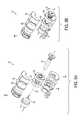
- FIG. 4depicts an isometric view of a motorized tube assembly, according to one embodiment of the present invention.
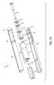
- FIG. 5depicts a partially-exploded, isometric view of the motorized tube assembly depicted in FIG. 4 .
- FIG. 6depicts an exploded, isometric view of the motor/controller unit depicted in FIG. 5 .
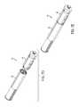
- FIGS. 7A and 7Bdepict exploded, isometric views of a motor/controller unit according to an alternative embodiment of the present invention.
- FIGS. 7C , 7 D and 7 Edepict isometric views of a motor/controller unit according to another alternative embodiment of the present invention.
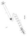
- FIG. 8Adepicts an exploded, isometric view of the power supply unit depicted in FIGS. 4 and 5 .
- FIG. 8Bdepicts an exploded, isometric view of a power supply unit according to an alternative embodiment of the present invention.
- FIG. 8Cdepicts an exploded, isometric view of a power supply unit according to an alternative embodiment of the present invention.
- FIGS. 9A and 9Bdepict exploded, isometric views of a power supply unit according to an alternative embodiment of the present invention.
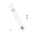
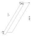
- FIG. 10presents a front view of a motorized roller shade, according to an embodiment of the present invention.
- FIG. 11presents a sectional view along the longitudinal axis of the motorized roller shade depicted in FIG. 10 .
- FIG. 12presents a front view of a motorized roller shade, according to an embodiment of the present invention.
- FIG. 13presents a sectional view along the longitudinal axis of the motorized roller shade depicted in FIG. 12 .
- FIG. 14presents a front view of a motorized roller shade, according to an embodiment of the present invention.
- FIG. 15presents a sectional view along the longitudinal axis of the motorized roller shade depicted in FIG. 14 .
- FIG. 16presents an isometric view of a motorized roller shade assembly in accordance with the embodiments depicted in FIGS. 10-15 .
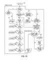
- FIG. 17presents a method 400 for controlling a motorized roller shade 20 , according to an embodiment of the present invention.
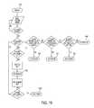
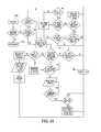
- FIGS. 18 to 25present operational flow charts illustrating various preferred embodiments of the present invention.
- shadeas used herein describes any flexible material, such as a shade, a curtain, a screen, etc., that can be deployed from, and retrieved onto, a storage tube.
- Embodiments of the present inventionprovide a remote controlled motorized roller shade in which the batteries, DC gear motor, control circuitry are entirely contained within a shade tube that is supported by bearings. Two support shafts are attached to respective mounting brackets, and the bearings rotatably couple the shade tube to each support shaft.
- the output shaft of the DC gear motoris fixed to one of the support shafts, while the DC gear motor housing is mechanically coupled to the shade tube. Accordingly, operation of the DC gear motor causes the motor housing to rotate about the fixed DC gear motor output shaft, which causes the shade tube to rotate about the fixed DC gear motor output shaft as well. Because these embodiments do not require external wiring for power or control, great flexibility in mounting, and re-mounting, the motorized roller shade is provided.
- Encapsulation of the motorization and control components within the shade tubegreatly increases the number of duty cycles provided by a single set of batteries and provides a highly efficient roller shade. Additionally, encapsulation advantageously prevents dust and other contaminants from entering the electronics and the drive components.
- the batteriesmay be mounted outside of the shade tube, and power may be provided to the components located within the shade tube using commutator or slip rings, induction techniques, and the like.
- the external batteriesmay be replaced by any external source of DC power, such as, for example, an AC/DC power converter, a solar cell, etc.
- FIGS. 1A and 1Bdepict complementary isometric views of a motorized roller shade assembly 10 having a reverse payout, in accordance with embodiments of the present invention.
- FIGS. 2A and 2Bdepict complementary isometric views of a motorized roller shade assembly 10 having a standard payout, in accordance with embodiments of the present invention, while FIG. 3 depicts an exploded, isometric view of the motorized roller shade assembly 10 depicted in FIG. 2B .
- motorized roller shade 20is mounted near the top portion of a window, door, etc., using mounting brackets 5 and 7 .
- motorized roller shade 20is mounted near the top portion of the window using mounting brackets 15 and 17 , which also support fascia 12 .
- fascia end caps 14 and 16attach to fascia 12 to conceal motorized roller shade 20 , as well as mounting brackets 15 and 17 .
- motorized roller shade 20includes a shade 22 and a motorized tube assembly 30 .
- motorized roller shade 20also includes a bottom bar 28 attached to the bottom of shade 22 .
- bottom bar 28provides an end-of-travel stop, while in an alternative embodiment, end-of-travel stops 24 and 26 may be provided.
- all of the components necessary to power and control the operation of the motorized roller shade 20are advantageously located within motorized tube assembly 30 .
- FIGS. 4 and 5depict isometric views of motorized tube assembly 30 , according to one embodiment of the present invention.
- Motorized tube assembly 30includes a shade tube 32 , motor/controller unit 40 and battery tube unit 80 .
- the top of shade 22is attached to the outer surface of shade tube 32 , while motor/controller unit 40 and battery tube unit 80 are located within an inner cavity defined by the inner surface of shade tube 32 .
- FIG. 6depicts an exploded, isometric view of the motor/controller unit 40 depicted in FIG. 5 .
- the motor/controller unit 40includes an electrical power connector 42 , a circuit board housing 44 , a DC gear motor 55 that includes a DC motor 50 and an integral motor gear reducing assembly 52 , a mount 54 for the DC gear motor 55 , and a bearing housing 58 .
- the electrical power connector 42includes a terminal 41 that couples to the power supply unit 80 , and power cables 43 that connect to the circuit board(s) located within the circuit board housing 44 .
- Terminal 41includes positive and negative connectors that mate with cooperating positive and negative connectors of power supply unit 80 , such as, for example, plug connectors, blade connectors, a coaxial connector, etc. In a preferred embodiment, the positive and negative connectors do not have a preferred orientation.
- the electrical power connector 42is mechanically coupled to the inner surface of the shade tube 32 using a press fit, an interference fit, a friction fit, a key, adhesive, etc.
- the circuit board housing 44includes an end cap 45 and a housing body 46 within which at least one circuit board 47 is mounted. In the depicted embodiment, two circuit boards 47 are mounted within the circuit board housing 44 in an orthogonal relationship. Circuit boards 47 generally include all of the supporting circuitry and electronic components necessary to sense and control the operation of the motor 50 , manage and/or condition the power provided by the power supply unit 80 , etc., including, for example, a controller or microcontroller, memory, a wireless receiver, etc.
- the microcontrolleris an Microchip 8-bit microcontroller, such as the PIC18F25K20, while the wireless receiver is a Micrel QwikRadio® receiver, such as the MICRF219.
- the microcontrollermay be coupled to the wireless receiver using a local processor bus, a serial bus, a serial peripheral interface, etc.
- the wireless receiver and microcontrollermay be integrated into a single chip, such as, for example, the Zensys ZW0201 Z-Wave Single Chip, etc.
- the antenna for the wireless receivermay mounted to the circuit board or located, generally, inside the circuit board housing 44 .
- the antennamay be located outside the circuit board housing 44 , including, for example, the outer surface of the circuit board housing 44 , the inner surface of the shade tube 32 , the outer surface of the shade tube 32 , the bearing housing 58 , etc.
- the circuit board housing 44may be mechanically coupled to the inner surface of the shade tube 32 using, for example, a press fit, an interference fit, a friction fit, a key, adhesive, etc.
- a wireless transmitteris also provided, and information relating to the status, performance, etc., of the motorized roller shade 20 may be transmitted periodically to a wireless diagnostic device, or, preferably, in response to a specific query from the wireless diagnostic device.
- the wireless transmitteris a Micrel QwikRadio® transmitter, such as the MICRF102.
- a wireless transceiverin which the wireless transmitter and receiver are combined into a single component, may also be included, and in one embodiment, the wireless transceiver is a Micrel RadioWire® transceiver, such as the MICRF506.
- the wireless transceiver and microcontrollermay be integrated into a single module, such as, for example, the Zensys ZM3102 Z-Wave Module, etc.
- the functionality of the microcontroller, as it relates to the operation of the motorized roller shade 20is discussed in more detail below.
- the shade tube 32includes one or more slots to facilitate the transmission of wireless signal energy to the wireless receiver, and from the wireless transmitter, if so equipped.
- the slotmay be advantageously matched to the wavelength of the signal.
- the slotis 1 ⁇ 8′′ wide and 21 ⁇ 2′′ long; other dimensions are also contemplated.
- the DC motor 50is electrically connected to the circuit board 47 , and has an output shaft that is connected to the input shaft of the motor gear reducing assembly 52 .
- the DC motor 50may also be mechanically coupled to the circuit board housing body 46 using, for example, a press fit, an interference fit, a friction fit, a key, adhesive, mechanical fasteners, etc.
- DC motor 50 and motor gear reducing assembly 52are provided as a single mechanical package, such as the DC gear motors manufactured by Baler Motor Inc.
- DC gear motor 55includes a 24V DC motor and a two-stage planetary gear system with a 40:1 ratio, such as, for example, Baler DC Gear Motor 1.61.077.423, and is supplied with an average battery voltage of 9.6V avg provided by an eight D-cell battery stack.
- a 24V DC motor and a two-stage planetary gear system with a 40:1 ratiosuch as, for example, Baler DC Gear Motor 1.61.077.423, and is supplied with an average battery voltage of 9.6V avg provided by an eight D-cell battery stack.
- Baler DC Gear Motor 1.61.077.423Baler DC Gear Motor 1.61.077.423
- an average battery voltage of 9.6V avgprovided by an eight D-cell battery stack.
- this preferred embodimentoffers particular advantages over many alternatives, including, for example, embodiments that include smaller average battery voltages, smaller battery sizes, 12V DC motors, three-stage planetary gear systems, etc.
- the 24V DC gear motor 55draws a current of about 0.1A when supplied with a battery voltage of 9.6V avg .
- a 12V DC gear motor with a similar gear systemsuch as, e.g., Baler DC Gear Motor 1.61.077.413, will draw a current of about 0.2A when supplied with a battery voltage of 4.8V avg .
- the 24V DC gear motor supplied with 9.6V avgadvantageously draws about 50% less current than the 12V DC gear motor supplied with 4.8V avg while producing the same power output.
- the rated voltage of the DC gear motoris much greater than the voltage produced by the batteries, by a factor of two or more, for example, causing the DC motor to operate at a reduced speed and torque rating, which advantageously eliminates undesirable higher frequency noise and draws lower current from the batteries, thereby improving battery life.
- applying a lower-than-rated voltage to the DC gear motorcauses the motor to run at a lower-than-rated speed to produce quieter operation and longer battery life as compared to a DC gear motor running at its rated voltage, which draws similar amperage while producing lower run cycle times to produce equivalent mechanical power.
- the 24V DC gear motorrunning at lower voltages, enhances the cycle life of the battery operated roller shade by about 20% when compared to a 12V DC gear motor using the same battery capacity.
- Alkaline, zinc and lead acid batteriesmay provide better performance than lithium or nickel batteries, for example.
- four D-cell batteriesproduce an average battery voltage of about 4.8V avg
- eight D-cell batteriesproduce an average battery voltage of about 9.6V avg
- embodiments that include an eight D-cell battery stackadvantageously provide twice as much battery capacity than those embodiments that include a four D-cell battery stack.
- smaller battery sizessuch as, e.g., C-cell, AA-cell, etc., offer less capacity than D-cells.
- supplying a 12V DC gear motor with 9.6V avgincreases the motor operating speed, which requires a higher gear ratio in order to provide the same output speed as the 24V DC gear motor discussed above.
- the motor operating speed of the 24V DC gear motorwill be about 50% of the motor operating speed of the 12V DC gear motor.
- the higher gear ratiotypically requires an additional planetary gear stage, which reduces motor efficiency, increases generated noise, reduces backdrive performance and may require a more complex motor controller. Consequently, those embodiments that include a 24V DC gear motor supplied with 9.6V avg offer higher efficiencies and less generated noise.
- the shaft 51 of DC motor 50protrudes into the circuit board housing 44 , and a multi-pole magnet 49 is attached to the end of the motor shaft 51 .
- a magnetic encoder(not shown for clarity) is mounted on the circuit board 47 to sense the rotation of the multi-pole magnet 49 , and outputs a pulse for each pole of the multi-pole magnet 49 that moves past the encoder.
- the multi-pole magnet 49has eight poles and the gear reducing assembly 52 has a gear ratio of 30:1, so that the magnetic encoder outputs 240 pulses for each revolution of the shade tube 32 .
- the controlleradvantageously counts these pulses to determine the operational and positional characteristics of the shade, curtain, etc.
- Other types of encodersmay also be used, such as optical encoders, mechanical encoders, etc.
- the number of pulses output by the encodermay be associated with a linear displacement of the shade 22 by a distance/pulse conversion factor or a pulse/distance conversion factor.
- this conversion factoris constant regardless of the position of shade 22 .
- the distance/pulse conversion factoris about 0.02 inches/pulse, while the pulse/distance conversion factor is about 48 pulses/inch.
- the outer diameter of the fully-wrapped shade 22may be used in the calculation.
- the outer diameter of the wrapped shade 22depends upon the thickness of the shade material.
- the outer diameter of the wrapped shade 22may be as small as 1.8 inches or as large as 2.5 inches.
- the distance/pulse conversion factoris about 0.03 inches/pulse, while the pulse/distance conversion factor is about 30 pulses/inch.
- any diameter between these two extremesi.e., the outer diameter of the shade tube 32 and the outer diameter of the wrapped shade 22 , may be used.
- the conversion factormay be a function of the position of the shade 22 , so that the conversion factor depends upon the calculated linear displacement of the shade 22 .
- the position of the shade 22is determined and controlled based on the number of pulses that have been detected from a known position of shade 22 . While the open position is preferred, the closed position may also be used as the known position. In order to determine the full range of motion of shade 22 , for example, the shade may be electrically moved to the open position, an accumulated pulse counter may be reset and the shade 22 may then be moved to the closed position, manually and/or electrically. The total number of accumulated pulses represents the limit of travel for the shade, and any desirable intermediate positions may be calculated based on this number.
- an 8 foot shade that moves from the open position to the closed positionmay generate 3840 pulses, and various intermediate positions of the shade 22 can be advantageously determined, such as, 25% open, 50% open, 75% open, etc. Quite simply, the number of pulses between the open position and the 75% open position would be 960, the number of pulses between the open position and the 50% open position would be 1920, and so on. Controlled movement between these predetermined positions is based on the accumulated pulse count. For example, at the 50% open position, this 8 foot shade would have an accumulated pulse count of 1920, and controlled movement to the 75% open position would require an increase in the accumulated pulse count to 2880.
- movement of the shade 22is determined and controlled based on accumulating the number of pulses detected since the shade 22 was deployed in the known position.
- An average number of pulses/inchmay be calculated based on the total number of pulses and the length of shade 22 , and an approximate linear displacement of the shade 22 can be calculated based on the number of pulses accumulated over a given time period.
- the average number of pulses/inchis 40, so movement of the shade 22 about 2 inches would generate about 80 pulses.
- Positional errorsare advantageously eliminated by resetting the accumulated pulse counter to zero whenever the shade 22 is moved to the known position.
- a mount 54supports the DC gear motor 55 , and may be mechanically coupled to the inner surface of the shade tube 32 .
- the outer surface of the mount 54 and the inner surface of the shade tube 32are smooth, and the mechanical coupling is a press fit, an interference fit, a friction fit, etc.
- the outer surface of the mount 54includes several raised longitudinal protrusions that mate with cooperating longitudinal recesses in the inner surface of the shade tube 32 .
- the mechanical couplingis keyed; a combination of these methods is also contemplated. If the frictional resistance is small enough, the motor/controller unit 40 may be removed from the shade tube 32 for inspection or repair; in other embodiments, the motor/controller unit 40 may be permanently secured within the shade tube 32 using adhesives, etc.
- the circuit board housing 44 and the mount 54may be mechanically coupled to the inner surface of the shade tube 32 . Accordingly, at least three different embodiments are contemplated by the present invention. In one embodiment, the circuit board housing 44 and the mount 54 are both mechanically coupled to the inner surface of the shade tube 32 . In another embodiment, only the circuit board housing 44 is mechanically coupled to the inner surface of the shade tube 32 . In a further embodiment, only the mount 54 is mechanically coupled to the inner surface of the shade tube 32 .
- the output shaft of the DC gear motor 55is fixed to the support shaft 60 , either directly (not shown for clarity) or through an intermediate shaft 62 .
- support shaft 60is attached to a mounting bracket that prevents the support shaft 60 from rotating. Because (a) the output shaft of the DC gear motor 55 is coupled to the support shaft 60 which is fixed to the mounting bracket, and (b) the DC gear motor 55 is mechanically-coupled to the shade tube, operation of the DC gear motor 55 causes the DC gear motor 55 to rotate about the fixed output shaft, which causes the shade tube 32 to rotate about the fixed output shaft as well.
- Bearing housing 58includes one or more bearings 64 that are rotatably coupled to the support shaft 60 .
- bearing housing 58includes two rolling element bearings, such as, for example, spherical ball bearings; each outer race is attached to the bearing housing 58 , while each inner race is attached to the support shaft 60 .
- two ball bearingsare spaced about 3 ⁇ 8′′ apart giving a total support land of about 0.8′′ or 20 mm; in an alternative embodiment, the intra-bearing spacing is about twice the diameter of support shaft 60 .
- Other types of low-friction bearingsare also contemplated by the present invention.
- the motor/controller unit 40may also include counterbalancing.
- motor/controller unit 40includes a fixed perch 56 attached to intermediate shaft 62 .
- mount 54functions as a rotating perch
- a counterbalance spring 63(not shown in FIG. 5 for clarity; shown in FIG. 6 ) is attached to the rotating perch 54 and the fixed perch 56 .
- the intermediate shaft 62may be hexagonal in shape to facilitate mounting of the fixed perch 56 . Preloading the counterbalance spring advantageously improves the performance of the motorized roller shade 20 .
- FIGS. 7A and 7Bdepict exploded, isometric views of a motor/controller unit 40 according to an alternative embodiment of the present invention.
- housing 67contains the major components of the motor/controller unit 40 , including DC gear motor 55 (e.g., DC motor 50 and motor gear reducing assembly 52 ), one or more circuit boards 47 with the supporting circuitry and electronic components described above, and at least one bearing 64 .
- the output shaft 53 of the DC gear motor 55is fixedly-attached to the support shaft 60 , while the inner race of bearing 64 is rotatably-attached support shaft 60 .
- at least one power spring 65is disposed within housing 67 , and is rotatably-attached to support shaft 60 .
- Housing 67may be formed from two complementary sections, fixed or removably joined by one or more screws, rivets, etc.
- FIGS. 7C , 7 D and 7 Edepict isometric views of a motor/controller unit 40 according to another alternative embodiment of the present invention.
- housing 68contains the DC gear motor 55 (e.g., DC motor 50 and motor gear reducing assembly 52 ), one or more circuit boards 47 with the supporting circuitry and electronic components described above, while housing 69 includes at least one bearing 64 .
- Housings 68 and 69may be attachable to one another, either removably or permanently.
- the output shaft 53 of the DC gear motor 55is fixedly-attached to the support shaft 60 , while the inner race of bearing 64 is rotatably-attached support shaft 60 .
- At least one power spring 65is disposed within housing 69 , and is rotatably-attached to support shaft 60 . While the depicted embodiment includes two power springs 65 , three (or more) power springs 65 may be used, depending on the counterbalance force required, the available space within shade tube 32 , etc. Housings 68 and 69 may be formed from two complementary sections, fixed or removably joined by one or more screws, rivets, etc.
- FIG. 8Adepicts an exploded, isometric view of the power supply unit 80 depicted in FIGS. 4 and 5 .
- the power supply unit 80includes a battery tube 82 , an outer end cap 86 , and a inner end cap 84 .
- the outer end cap 86includes one or more bearings 90 that are rotatably coupled to a support shaft 88 .
- outer end cap 86includes two low-friction rolling element bearings, such as, for example, spherical ball bearings, separated by a spacer 91 ; each outer race is attached to the outer end cap 86 , while each inner race is attached to the support shaft 88 .
- Other types of low-friction bearingsare also contemplated by the present invention.
- bearings 86are simply bearing surfaces, preferably low-friction bearing surfaces, while in another alternative embodiment, support shaft 88 is fixedly attached to the outer end cap 86 , and the external shade support bracket provides the bearing surface for the support shaft 88 .
- the outer end cap 86is removable and the inner cap 84 is fixed.
- the inner end cap 84may be removable and the outer end cap 86 may be fixed, both end caps may be removable, etc.
- the removable end cap(s)may be threaded, slotted, etc.
- the outer end cap 86also includes a positive terminal that is coupled to the battery tube 82 .
- the inner end cap 84includes a positive terminal coupled to the battery tube 82 , and a negative terminal coupled to a conduction spring 85 .
- the positive terminal of the outer end cap 86is electrically coupled to the positive terminal of one of the batteries in the battery stack 92
- the negative terminal of the inner end cap 84is electrically coupled to the negative terminal of another one of the batteries in the battery stack 92 .
- the positive and negative terminalsmay be reversed, so that the conduction spring 85 contacts the positive terminal of one of the batteries in the battery stack 92 , etc.
- the outer end cap 86 and the inner end cap 84are mechanically coupled to the inner surface of the shade tube 32 .
- the outer surface of the mount 84 and the inner surface of the shade tube 32are smooth, and the mechanical coupling is a press fit, an interference fit, a friction fit, etc.
- the outer surface of the mount 84includes several raised longitudinal protrusions that mate with cooperating longitudinal recesses in the inner surface of the shade tube 32 .
- the mechanical couplingis keyed; a combination of these methods is also contemplated.
- the frictional resistanceshould be small enough such that the power supply unit 80 can be removed from the shade tube 32 for inspection, repair and battery replacement.
- the battery stack 92includes eight D-cell batteries connected in series to produce an average battery stack voltage of 9.6V avg .
- Other battery sizes, as well as other DC power sources disposable within battery tube 82are also contemplated by the present invention.
- the electrical connector 42is fitted within the inner cavity of shade tube 32 to a predetermined location; power cables 43 has a length sufficient to permit the remaining sections of the motor/controller unit 40 to remain outside the shade tube 32 until the electrical connector 42 is properly seated.
- the remaining sections of the motor/controller unit 40are then fitted within the inner cavity of shade tube 32 , such that the bearing housing 58 is approximately flush with the end of the shade tube 32 .
- the power supply unit 80is then inserted into the opposite end until the positive and negative terminals of the inner end cap 84 engage the terminal 41 of the electrical connector 42 .
- the outer end cap 86should be approximately flush with end of the shade tube 32 .
- the outer end cap 86is mechanically coupled to the inner surface of the shade tube 32 using a press fit, interference fit, an interference member, such as O-ring 89 , etc., while the inner end cap 81 is not mechanically coupled to the inner surface of the shade tube 32 .
- the shade tube 32functions as the battery tube 82 , and the battery stack 92 is simply inserted directly into shade tube 32 until one end of the battery stack 92 abuts the inner end cap 84 .
- the positive terminal of the outer end cap 86is coupled to the positive terminal of the inner end cap 84 using a wire, foil strip, trace, etc.
- the positive and negative terminalsmay be reversed, so that the respective negative terminals are coupled.
- the batteriesmay be mounted outside of the shade tube, and power may be provided to the components located within the shade tube using commutator or slip rings, induction techniques, and the like.
- the external batteriesmay be replaced by any external source of DC power, such as, for example, an AC/DC power converter, a solar cell, etc.
- FIGS. 9A and 9Bdepict exploded, isometric views of a power supply unit according to an alternative embodiment of the present invention.
- power supply unit 80includes a housing 95 with one or more bearings 90 that are rotatably coupled to a support shaft 88 , a power coupling 93 to receive power from an external power source, and positive and negative terminals to engage the electrical connector 42 .
- Power cables 97(shown in phantom for clarity) extend from the power coupling 93 , through a hollow central portion of support shaft 88 , to an external DC power source.
- housing 95includes two low-friction rolling element bearings 90 , such as, for example, spherical ball bearings; each outer race is attached to the housing 95 , while each inner race is attached to the support shaft 88 .
- low-friction rolling element bearings 90such as, for example, spherical ball bearings
- Housing 95may be formed from two complementary sections, fixed or removably joined by one or more screws, rivets, etc.
- the support shafts 88are slidingly-attached to the inner race of ball bearings 90 so that the support shafts 88 may be displaced along the rotational axis of the shade tube 32 .
- This adjustabilityadvantageously allows an installer to precisely attach the end of the support shafts 88 to the respective mounting bracket by adjusting the length of the exposed portion of the support shafts 88 .
- outer end cap 86 and housing 95may provide approximately 0.5′′ of longitudinal movement for the support shafts 88 .
- mounting brackets 5 , 7 , 15 and 17are embossed so that the protruding portion of the mounting bracket will only contact the inner race of bearings 64 and 90 and will not rub against the edge of the shade or the shade tube 32 if the motorized roller shade 20 is installed incorrectly.
- the bearingsmay accommodate up to 0.125′′ of misalignment due to installation errors without a significant reduction in battery life.
- the microcontrollerreceives control signals from a wired remote control. These control signals may be provided to the microcontroller in various ways, including, for example, over power cables 97 , over additional signal lines that are accommodated by power coupling 93 , over additional signal lines that are accommodated by a control signal coupling (not shown in FIGS. 9 A,B for clarity), etc.
- FIGS. 10-16Various additional embodiments of the present invention are presented in FIGS. 10-16 .
- FIGS. 10 and 11depict an alternative embodiment of the present invention without counterbalancing;
- FIG. 10presents a front view of a motorized roller shade 120
- FIG. 11presents a sectional view along the longitudinal axis of the motorized roller shade 120 .
- the output shaft of the DC gear motor 150is attached to the support shaft 160 , and an intermediate shaft is not included.
- FIGS. 12 and 13depict an alternative embodiment of the present invention with counterbalancing;
- FIG. 12presents a front view of a motorized roller shade 220
- FIG. 13presents a sectional view along the longitudinal axis of the motorized roller shade 220 .
- FIGS. 14 and 15depict an alternative embodiment of the present invention with counterbalancing;
- FIG. 14presents a front view of a motorized roller shade 320
- FIG. 15presents a sectional view along the longitudinal axis of the motorized roller shade 320 .
- the output shaft of the DC gear motor 350is attached to the intermediate shaft 362 .
- a power spring 390couples the intermediate shaft 362 to the inner surface of the shade tube 332 .
- FIG. 16presents an isometric view of a motorized roller shade assemblies 120 , 220 , 320 in accordance with the embodiments depicted in FIGS. 10-15 .
- Motorized roller shade 20may be controlled manually and/or remotely using a wireless or wired remote control.
- the microcontrollerexecutes instructions stored in memory that sense and control the motion of DC gear motor 55 , decode and execute commands received from the remote control, monitor the power supply voltage, etc. More than one remote control may be used with a single motorized roller shade 20 , and a single remote control may be used with more than one motorized roller shade 20 .
- FIG. 17presents a method 400 for controlling a motorized roller shade 20 , according to an embodiment of the present invention.
- method 400includes a manual control portion 402 and a remote control portion 404 .
- method 400includes the manual control portion 402
- method 400includes the remote control portion 404
- method 400includes both the manual control portion 402 and the remote control portion 404 .
- a manual movement of the shade 22is detected ( 410 ), a displacement associated with the manual movement is determined ( 420 ), and, if the displacement is less than a maximum displacement, the shade 22 is moved ( 430 ) to a different position by rotating the shade tube 32 using the DC gear motor 55 .
- the microcontrollerdetects a manual downward movement of the shade 22 by monitoring a reed switch, while in an alternative embodiment, the microcontroller simply monitors the encoder.
- the microcontrollerbegins to count the encoder pulses generated by the rotation of the shade tube 32 relative to the fixed motor shaft 51 .
- the encoder pulsescease, the downward movement has stopped, and the displacement of the shade 22 is determined and then compared to a maximum displacement.
- the shade displacementis simply the total number of encoder pulses received by the microcontroller, and the maximum displacement is a predetermined number of encoder pulses.
- the microcontrollerconverts the encoder pulses to a linear distance, and then compares the calculated linear distance to a maximum displacement, such as 2 inches.
- the maximum number of encoder pulsesis 80, which may represent approximately 2 inches of linear shade movement in certain embodiments. If the total number of encoder pulses received by the microcontroller is greater than or equal to 80, then the microcontroller does not energize the DC gear motor 55 and the shade 22 simply remains at the new position. On the other hand, if the total number of encoder pulses received by the microcontroller is less than 80, then the microcontroller moves the shade 22 to a different position by energizing the DC gear motor 55 to rotate the shade tube 32 . After the microcontroller determines that the shade 22 has reached the different position, the DC gear motor 55 is de-energized.
- the microcontrollermaintains the current position of the shade 22 by accumulating the number of encoder pulses since the shade 22 was deployed in the known position.
- the known (e.g., open) positionhas an accumulated pulse count of 0, and the various intermediate positions each have an associated accumulated pulse count, such as 960, 1920, etc.
- the microcontrollerincrements the accumulated pulse counter, and when the shade 22 moves in the upward direction, the microcontroller decrements the accumulated pulse counter.
- Each pulse received from the encoderincrements or decrements the accumulated pulse counter by one count.
- the microcontrollermay convert each pulse count to a linear distance, and perform these calculations in units of inches, millimeters, etc.
- limited manual downward movement of the shade 22causes the microcontroller to move the shade to a position located directly above the current position, such as 25% open, 50% open, 75% open, 100% open, etc.
- a position located directly above the current positionsuch as 25% open, 50% open, 75% open, 100% open, etc.
- Each of these predetermined positionshas an associated accumulated pulse count, and the microcontroller determines that the shade 22 has reached the different position by comparing the value in the accumulated pulse counter to the accumulated pulse count of the predetermined position; when the accumulated pulse counter equals the predetermined position accumulated pulse count, the shade 22 has reached the different position.
- ⁇⁇ ⁇ ⁇ ⁇ ⁇ ⁇ ⁇ ⁇ ⁇ ⁇ ⁇ ⁇ ⁇ ⁇ ⁇ ⁇ ⁇ ⁇ ⁇ ⁇ ⁇ ⁇ ⁇ ⁇ ⁇ ⁇ ⁇ ⁇ ⁇ ⁇ ⁇ ⁇ ⁇ ⁇ ⁇ ⁇ ⁇ ⁇ ⁇ ⁇ ⁇ ⁇ ⁇ ⁇ ⁇ ⁇ ⁇ ⁇ ⁇ ⁇ ⁇ ⁇ ⁇ ⁇ ⁇ ⁇ ⁇ ⁇ ⁇ ⁇ ⁇ ⁇ ⁇ ⁇ ⁇ ⁇ ⁇ ⁇ ⁇ ⁇ ⁇ ⁇ ⁇ ⁇ ⁇ ⁇ ⁇ ⁇ ⁇ ⁇ ⁇ ⁇ ⁇ ⁇ ⁇ ⁇ ⁇ ⁇ ⁇ ⁇ ⁇ ⁇ ⁇ ⁇ ⁇ ⁇ ⁇ ⁇ ⁇ ⁇ ⁇ ⁇ ⁇ ⁇ ⁇ ⁇ ⁇ ⁇ ⁇ ⁇ ⁇ ⁇ ⁇ ⁇ ⁇ ⁇ ⁇ ⁇ ⁇ ⁇ ⁇ ⁇ ⁇ ⁇ ⁇
- Manual upward movement of the shade 22may be detected and measured using an encoder that senses direction as well as rotation, such as, for example, an incremental rotary encoder, a relative rotary encoder, a quadrature encoder, etc.
- limited upward movement of the shade 22causes the microcontroller to move the shade to a position located above the current position, etc.
- a commandis received ( 440 ) from a remote control, and the shade 22 is moved ( 450 ) to a position associated with the command.
- the remote controlis a wireless transmitter that has several shade position buttons that are associated with various commands to move the shade 22 to different positions.
- the buttonsactivate switches that may be electro-mechanical, such as, for example, momentary contact switches, etc, electrical, such as, for example, a touch pad, a touch screen, etc.
- the wireless transmittersends a message to the motorized roller shade 20 that includes a transmitter identifier and a command associated with the activated button.
- the remote controlis pre-programmed such that each shade position button will command the shade to move to a predetermined position.
- remote control functionalitymay be embodied within a computer program, and this program may be advantageously hosted on a wireless device, such as an iPhone.
- the wireless devicemay communicate directly with the motorized roller shade 20 , or though an intermediate gateway, bridge, router, base station, etc.
- the motorized roller shade 20includes a wireless receiver that receives, decodes and sends the message to the microcontroller for further processing.
- the messagemay be stored within the wireless transmitter and then sent to the microcontroller immediately after decoding, or the message may be sent to the microcontroller periodically, e.g., upon request by the microcontroller, etc.
- One preferred wireless protocolis the Z-Wave Protocol, although other wireless communication protocols are contemplated by the present invention.
- the microcontrollerinterprets the command and sends an appropriate control signal to the DC gear motor 55 to move the shade in accordance with the command.
- the DC gear motor 55 and shade tube 32rotate together, which either extends or retracts the shade 22 .
- the messagemay be validated prior to moving the shade, and the command may be used during programming to set a predetermined deployment of the shade.
- the microcontrollerdecrements the accumulated pulse counter by one count every time a pulse is received from the encoder, and when the accumulated pulse counter reaches 1920, the microcontroller de-energizes the DC gear motor 55 , which stops the shade 22 at the 50% open position. In one embodiment, if a different command is received while the shade 22 is moving, the microcontroller may stop the movement of the shade 22 .
- the microcontrollermay de-energize the DC gear motor 55 to stop the movement of the shade 22 .
- the microcontrollermay de-energize the DC gear motor 55 to stop the movement of the shade 22 .
- a command to move the shade to the 100% open positionresets the accumulated pulse counter to 0, and the microcontroller de-energizes the DC gear motor 55 when the encoder pulses cease.
- an end-of-travel stopsuch as bottom bar 28 , stops 24 and 26 , and the like, engage corresponding structure on the mounting brackets when the shade 22 has been retracted to the 100% open position. This physical engagement stops the rotation of the shade tube 32 and stalls the DC gear motor 55 .
- the microcontrollersenses that the encoder has stopped sending pulses, e.g., for one second, and de-energizes the DC gear motor 55 .
- the microcontrollermay check an end-of-travel pulse count in order to prevent the shade 22 from extending past a preset limit.
- the movement of the shade 22may simply be determined using relative pulse counts. For example, if the current position of the shade 22 is 100% open, and a command to move the shade 22 to the 50% open position is received, the microcontroller may simply energize the DC gear motor 55 until a certain number of pulses have been received, by the microcontroller, from the encoder. In other words, the pulse count associated with predetermined position is relative to the predetermined position located directly above or below, rather than the known position.
- FIGS. 20 to 24For the preferred embodiment, programming a motorized roller shade 20 to accept commands from a particular remote control depicted in FIGS. 18 and 25 , while programming or teaching the motorized roller shade 20 to deploy and retract the shade 22 to various preset or predetermined positions, such as open, closed, 25% open, 50% open, 75% open, etc., is depicted in FIGS. 20 to 24 .
- Other programming methodologiesare also contemplated by the present invention.
- a brakemay be applied to the motorized roller shade 20 to stop the movement of the shade 22 , as well as to prevent undesirable rotation or drift after the shade 22 has been moved to a new position.
- the microcontrollerconnects the positive terminal of the DC gear motor 55 to the negative terminal of DC gear motor 55 , using one or more electro-mechanical switches, power FETS, MOSFETS, etc., to apply the brake.
- the positive and negative terminals of the DC gear motor 55may be connected to ground, which may advantageously draw negligible current. In a negative ground system, the negative terminal of the DC gear motor 55 is already connected to ground, so the microcontroller only needs to connect the positive terminal of the DC gear motor 55 to ground. Conversely, in a positive ground system, the positive terminal of the DC gear motor 55 is already connected to ground, so the microcontroller only needs to connect the negative terminal of the DC gear motor 55 to ground.
- any rotation of the shade tube 32will cause the DC gear motor 55 to generate a voltage, or counter electromotive force, which is fed back into the DC gear motor 55 to produce a dynamic braking effect.
- Other braking mechanismsare also contemplated by the present invention, such as friction brakes, electro-mechanical brakes, electro-magnetic brakes, permanent-magnet single-face brakes, etc.
- the microcontrollerreleases the brake after a manual movement of the shade 22 is detected, as well as prior to energizing the DC gear motor 55 to move the shade 22 .
- the positive or negative terminal of the DC gear motor 55is connected to ground to apply the maximum amount of braking force and bring the shade 22 to a complete stop.
- the microcontrollerthen connects the positive and negative terminals of the DC gear motor 55 together via a low-value resistor, using an additional MOSFET, for example, to apply a reduced amount of braking force to the shade 22 , which prevents the shade 22 from drifting but allows the user to tug the shade 22 over long displacements without significant resistance.
- the brakeis not released after the manual movement of the shade is detected in order to provide a small amount of resistance during the manual movement.
- FIGS. 18 to 25present operational flow charts illustrating preferred embodiments of the present invention.
- the functionality illustrated thereinis implemented, generally, as instructions executed by the microcontroller.
- FIG. 18depicts a Main Loop 500 that includes a manual control operational flow path, a remote control operational flow path, and a combined operational flow path.
- Main Loop 500exits to various subroutines, including subroutine “TugMove” 600 ( FIG. 19 ), subroutine “Move25” 700 ( FIG. 20 ), subroutine “Move50” 800 ( FIG. 21 ), subroutine “Move75” 900 ( FIG. 22 ), subroutine “MoveUp” 1000 ( FIG. 23 ), subroutine “MoveDown” 1100 ( FIG. 24 ), which return control to Main Loop 500 .
- Subroutine “Power-Up” 1200( FIG. 25 ) is executed upon power up, and then exits to Main Loop 500 .
- the shade tube 32is an aluminum tube having an outer diameter of 1.750 inches and a wall thickness of 0.062 inches.
- Bearings 64 and 90each include two steel ball bearings, 30 mm OD ⁇ 10 mm ID ⁇ 9 mm wide, that are spaced 0.250′′ apart. In other words, a total of four ball bearings, two at each end of the motorized roller shade 20 , are provided.
- the DC gear motor 55is a Büler DC gear motor 1.61.077.423, as discussed above.
- the battery tube 82accommodates 6 to 8 D-cell alkaline batteries, and supplies voltages ranges from 6 V to 12 V, depending on the number of batteries, shelf life, cycles of the shade tube assembly, etc.
- the shade 22is a flexible fabric that is 34 inches wide, 60 inches long, 0.030 inches thick and weighs 0.100 lbs/sq. ft, such as, for example, Phifer Q89 Wicker/Brownstone.
- An aluminum circularly-shaped curtain bar 28having a diameter of 0.5 inches, is attached to the shade 22 to provide taughtness as well as an end-of-travel stop.
- the counterbalance spring 63is a clock spring that provides 1.0 to 1.5 in-lb of counterbalance torque to the shade 22 after it has reached 58 inches of downward displacement.
- the current drawn by the Baler DC gear motorranges between 0.06 and 0.12 amps, depending on friction.
Landscapes
- Engineering & Computer Science (AREA)
- Structural Engineering (AREA)
- Architecture (AREA)
- Civil Engineering (AREA)
- Operating, Guiding And Securing Of Roll- Type Closing Members (AREA)
- Control Of Direct Current Motors (AREA)
Abstract
Description
Claims (26)
Priority Applications (26)
| Application Number | Priority Date | Filing Date | Title |
|---|---|---|---|
| US12/711,192US8299734B2 (en) | 2010-02-23 | 2010-02-23 | High efficiency roller shade |
| JP2012555106AJP5822276B2 (en) | 2010-02-23 | 2011-02-23 | High efficiency roller shade |
| CA3015412ACA3015412C (en) | 2010-02-23 | 2011-02-23 | High efficiency roller shade |
| EP14151185.7AEP2722477B1 (en) | 2010-02-23 | 2011-02-23 | Arrangement of a tubular motor in the winding shaft of a roller blind |
| CN201410030997.5ACN103953275B (en) | 2010-02-23 | 2011-02-23 | Efficient roller shutter |
| PCT/US2011/025889WO2011106397A1 (en) | 2010-02-23 | 2011-02-23 | High efficiency roller shade |
| CA2790725ACA2790725C (en) | 2010-02-23 | 2011-02-23 | High efficiency roller shade |
| CN201180020280.7ACN103108575B (en) | 2010-02-23 | 2011-02-23 | High-efficiency roller shutter |
| CA2919825ACA2919825C (en) | 2010-02-23 | 2011-02-23 | High efficiency roller shade |
| AU2011220886AAU2011220886B2 (en) | 2010-02-23 | 2011-02-23 | High efficiency roller shade |
| EP11747979.0AEP2538823B1 (en) | 2010-02-23 | 2011-02-23 | Motor driven roller shade winding shaft comprising an integrated power supply |
| US13/276,963US8659246B2 (en) | 2010-02-23 | 2011-10-19 | High efficiency roller shade |
| US13/847,607US8791658B2 (en) | 2010-02-23 | 2013-03-20 | High efficiency roller shade |
| US13/921,950US9194179B2 (en) | 2010-02-23 | 2013-06-19 | Motorized shade with the transmission wire passing through the support shaft |
| US14/097,358US9376863B2 (en) | 2010-02-23 | 2013-12-05 | High efficiency roller shade |
| AU2014200269AAU2014200269C1 (en) | 2010-02-23 | 2014-01-16 | High efficiency roller shade |
| JP2014030674AJP5826873B2 (en) | 2010-02-23 | 2014-02-20 | High efficiency roller shade |
| US14/251,427US9249623B2 (en) | 2010-02-23 | 2014-04-11 | Low-power architectural covering |
| US14/512,597US9376862B2 (en) | 2010-02-23 | 2014-10-13 | Method for operating a motorized roller shade |
| US14/873,714US9394743B2 (en) | 2010-02-23 | 2015-10-02 | Motorized shade with the transmission wire passing through the support shaft |
| US15/063,783US9611690B2 (en) | 2010-02-23 | 2016-03-08 | High efficiency roller shade |
| US15/166,367US9745797B2 (en) | 2010-02-23 | 2016-05-27 | Method for operating a motorized shade |
| US15/184,504US9725952B2 (en) | 2010-02-23 | 2016-06-16 | Motorized shade with transmission wire passing through the support shaft |
| US15/437,283US9771755B2 (en) | 2010-02-23 | 2017-02-20 | High efficiency roller shade |
| US15/629,398US9890585B2 (en) | 2010-02-23 | 2017-06-21 | Method for operating a motorized shade |
| US15/634,009US9896882B2 (en) | 2010-02-23 | 2017-06-27 | Motorized shade with the transmission wire passing through the support shaft |
Applications Claiming Priority (1)
| Application Number | Priority Date | Filing Date | Title |
|---|---|---|---|
| US12/711,192US8299734B2 (en) | 2010-02-23 | 2010-02-23 | High efficiency roller shade |
Related Parent Applications (1)
| Application Number | Title | Priority Date | Filing Date |
|---|---|---|---|
| US13/771,994Continuation-In-PartUS9018868B2 (en) | 2010-02-23 | 2013-02-20 | High efficiency roller shade and method for setting artificial stops |
Related Child Applications (1)
| Application Number | Title | Priority Date | Filing Date |
|---|---|---|---|
| US13/276,963Continuation-In-PartUS8659246B2 (en) | 2010-02-23 | 2011-10-19 | High efficiency roller shade |
Publications (2)
| Publication Number | Publication Date |
|---|---|
| US20110203748A1 US20110203748A1 (en) | 2011-08-25 |
| US8299734B2true US8299734B2 (en) | 2012-10-30 |
Family
ID=44475497
Family Applications (1)
| Application Number | Title | Priority Date | Filing Date |
|---|---|---|---|
| US12/711,192Expired - Fee RelatedUS8299734B2 (en) | 2010-02-23 | 2010-02-23 | High efficiency roller shade |
Country Status (7)
| Country | Link |
|---|---|
| US (1) | US8299734B2 (en) |
| EP (2) | EP2538823B1 (en) |
| JP (2) | JP5822276B2 (en) |
| CN (2) | CN103953275B (en) |
| AU (1) | AU2011220886B2 (en) |
| CA (3) | CA3015412C (en) |
| WO (1) | WO2011106397A1 (en) |
Cited By (47)
| Publication number | Priority date | Publication date | Assignee | Title |
|---|---|---|---|---|
| US20110297334A1 (en)* | 2009-02-09 | 2011-12-08 | Hunter Douglas Industries B.V. | Spring system for roller blinds |
| US20120024485A1 (en)* | 2010-05-04 | 2012-02-02 | Willis Jay Mullet | Modular anti-reversible power spring apparatus and method |
| US20130025802A1 (en)* | 2011-07-27 | 2013-01-31 | Rheal Hamelin | Door structure for temporary shelters |
| US20130025804A1 (en)* | 2011-07-27 | 2013-01-31 | Chung Hsien Hsieh | Door machine of fireproof door |
| US8659246B2 (en) | 2010-02-23 | 2014-02-25 | Homerun Holdings Corporation | High efficiency roller shade |
| US20140076508A1 (en)* | 2012-09-17 | 2014-03-20 | Homerun Holdings Corporation | Drapery tube incorporating batteries within the drapery tube, with a stop for facilitating the loading and unloading of the batteries |
| US8723455B2 (en) | 2012-04-25 | 2014-05-13 | Homerun Holdings Corporation | Quick change battery arrangement for motorized shade |
| US8739854B2 (en)* | 2012-07-02 | 2014-06-03 | Qmotion Incorporated | Pre-assembled and pre-tensioned shade with indexing gear tensioner |
| WO2015006270A1 (en)* | 2013-07-10 | 2015-01-15 | Qmotion Incorporated | Battery retaining system and method for motorized architectural coverings |
| US9074414B1 (en)* | 2011-04-06 | 2015-07-07 | John Steffi | Roll up guard curtain |
| US9194179B2 (en) | 2010-02-23 | 2015-11-24 | Qmotion Incorporated | Motorized shade with the transmission wire passing through the support shaft |
| US9249623B2 (en) | 2010-02-23 | 2016-02-02 | Qmotion Incorporated | Low-power architectural covering |
| US20160201389A1 (en)* | 2013-04-17 | 2016-07-14 | Qmotion Incorporated | System and Method for Manual and Motorized Manipulation of an Architectural Covering |
| US9410371B2 (en) | 2009-01-14 | 2016-08-09 | Hunter Douglas Inc. | Noise dampening motor drive system for retractable covering for architectural openings |
| US20170081917A1 (en)* | 2015-09-18 | 2017-03-23 | The Watt Stopper, Inc. | Hardwired and wirelessly controlled motorized window shades system and method of use |
| US9725948B2 (en) | 2010-02-23 | 2017-08-08 | The Watt Stopper, Inc. | High efficiency roller shade and method for setting artificial stops |
| US9801486B2 (en) | 2014-05-19 | 2017-10-31 | Current Products Corp. | Crossover bracket for drapery |
| US9834986B2 (en) | 2012-02-27 | 2017-12-05 | Hunter Douglas Industries B.V. | Architectural covering having a drive mechanism |
| US9999313B2 (en) | 2013-04-11 | 2018-06-19 | Current Products Corp. | Motorized drapery apparatus, system and method of use |
| US10221622B2 (en) | 2015-09-08 | 2019-03-05 | Crestron Electronics, Inc. | Roller shade with a pretensioned spring and method for pretensioning the spring |
| US10435945B2 (en) | 2014-11-10 | 2019-10-08 | Hunter Douglas Inc. | Covering for an architectural opening including multiple stage spring assembly |
| US10590701B2 (en) | 2013-03-14 | 2020-03-17 | Hunter Douglas Inc. | Methods and apparatus to control an architectural opening covering assembly |
| CZ308287B6 (en)* | 2018-10-29 | 2020-04-15 | Bestadom, s.r.o. | Roller shutter mechanism |
| US10648232B2 (en) | 2012-10-03 | 2020-05-12 | Hunter Douglas Inc. | Methods and apparatus to control an architectural opening covering assembly |
| US10676989B2 (en) | 2016-02-19 | 2020-06-09 | Hunter Douglas Inc. | Motor assembly for an architectural covering |
| US10684542B2 (en) | 2017-05-16 | 2020-06-16 | Draper, Inc. | Projection screen system |
| US10738530B2 (en) | 2018-01-16 | 2020-08-11 | Crestron Electronics, Inc. | Motor pretensioned roller shade |
| US10851587B2 (en) | 2016-10-19 | 2020-12-01 | Hunter Douglas Inc. | Motor assemblies for architectural coverings |
| US10975619B2 (en) | 2011-10-03 | 2021-04-13 | Hunter Douglas Inc. | Methods and apparatus to control architectural opening covering assemblies |
| US11002071B2 (en) | 2018-03-29 | 2021-05-11 | Crestron Electronics, Inc. | Architectural roller shade housing with adjustable battery compartment |
| US11072976B2 (en) | 2017-02-06 | 2021-07-27 | Hunter Douglas, Inc. | Methods and apparatus to reduce noise in motor assemblies |
| US11111907B1 (en) | 2018-05-13 | 2021-09-07 | Tpe Midstream Llc | Fluid transfer and depressurization system |
| US11203899B2 (en) | 2018-03-12 | 2021-12-21 | Roll-A-Shade Inc. | Solar-powered intelligent automated motorized window treatment with increased energy efficiency and method of using same |
| US11234549B2 (en) | 2018-01-26 | 2022-02-01 | Current Products Corp. | Grommet drapery system |
| US20220041403A1 (en)* | 2019-03-29 | 2022-02-10 | Tim McCullagh | Roller apparatus for a cover and method of use thereof |
| US11293224B2 (en) | 2017-03-14 | 2022-04-05 | Roll-A-Shade, Inc. | Intelligent automated motorized window treatment with increased energy efficiency and method of using same |
| US11299932B2 (en) | 2017-10-09 | 2022-04-12 | Hunter Douglas, Inc. | Rail assemblies for motorized architectural coverings and related methods |
| US11314159B2 (en)* | 2020-06-08 | 2022-04-26 | Draper, Inc. | Projection screen system and method for mounting the same |
| US11457763B2 (en) | 2019-01-18 | 2022-10-04 | Current Products Corp. | Stabilized rotating drapery rod ring system |
| US11486198B2 (en) | 2019-04-19 | 2022-11-01 | Hunter Douglas Inc. | Motor assemblies for architectural coverings |
| US11744393B2 (en) | 2018-01-26 | 2023-09-05 | Current Products Corp. | Tabbed drapery system |
| US11788348B2 (en) | 2020-05-22 | 2023-10-17 | Lutron Technology Company Llc | Battery-operated window treatment |
| US11905758B2 (en) | 2020-07-02 | 2024-02-20 | Springs Window Fashions, Llc | Roller shade assembly |
| US12143039B2 (en) | 2020-05-22 | 2024-11-12 | Lutron Technology Company Llc | Energy-supply system for supplying energy to an electrical load from a battery |
| US12152436B2 (en) | 2021-08-06 | 2024-11-26 | Lutron Technology Company Llc | Battery-powered Roman shade system |
| US12378819B2 (en) | 2021-07-30 | 2025-08-05 | Lutron Technology Company Llc | Motorized window treatment |
| US20250269706A1 (en)* | 2024-02-26 | 2025-08-28 | Intellectual Property Group, LLC | Automatic Tarp Control System and Method for Dump Trucks |
Families Citing this family (37)
| Publication number | Priority date | Publication date | Assignee | Title |
|---|---|---|---|---|
| US8299734B2 (en)* | 2010-02-23 | 2012-10-30 | Homerun Holdings Corporation | High efficiency roller shade |
| CN102946767B (en) | 2010-05-28 | 2016-11-23 | 亨特道格拉斯公司 | The architectural opening shelter of power is provided by turning motor |
| US12044068B2 (en) | 2011-03-11 | 2024-07-23 | Lutron Technology Company Llc | Battery-powered motorized window treatment having a service position |
| CN103620150B (en) | 2011-03-11 | 2015-12-23 | 路创电子公司 | Electric Curtain Handling Device |
| US9045939B2 (en) | 2011-03-11 | 2015-06-02 | Lutron Electronics Co., Inc. | Battery-powered motorized window treatment having a service position |
| US9810020B2 (en) | 2011-03-11 | 2017-11-07 | Lutron Electronics Co., Inc. | Motorized window treatment |
| US10655386B2 (en) | 2011-03-11 | 2020-05-19 | Lutron Technology Company Llc | Motorized window treatment |
| US8960260B2 (en)* | 2011-11-01 | 2015-02-24 | Homerun Holdings Corporation | Motorized roller shade or blind having an antenna and antenna cable connection |
| SG11201401831YA (en)* | 2012-05-16 | 2014-10-30 | Ningbo Xianfeng New Mat Co Ltd | Multifunctional integrated window |
| US10934773B2 (en) | 2012-06-13 | 2021-03-02 | Somfy Activites Sa | Motorized manoeuvring device intended to manoeuvre a moving windable fabric screen of a window or projection screen cover device |
| FR2992114B1 (en) | 2012-06-13 | 2016-08-19 | Somfy Sas | MOTORIZED MANEUVER DEVICE FOR MANEUVERING A MOBILE SCREEN WITH A WINDABLE CANVAS OF A WINDOW COVER OR PROJECTION SCREEN DEVICE. |
| FR2992142B1 (en)* | 2012-06-13 | 2014-07-11 | Somfy Sas | ELEMENT FOR SUPPORTING A BATTERY IN A WINDOW TUBE OF A DOMOTIC SCREEN |
| US20130333848A1 (en)* | 2012-06-15 | 2013-12-19 | Homerun Holdings Corporation | Motorized roller shade configured for larger shade applications |
| US9115537B2 (en) | 2013-02-15 | 2015-08-25 | Lutron Electronics Co., Inc. | Battery-powered roller shade system |
| US9206634B1 (en)* | 2013-03-15 | 2015-12-08 | Overhead Door Corporation | Counterbalance system for vertical acting doors |
| CN105164360B (en) | 2013-04-15 | 2017-04-26 | 卢特龙电子公司 | Motorized window treatment with integrated accessible battery compartment |
| US10094169B2 (en) | 2014-11-01 | 2018-10-09 | Lutron Electronics Co., Inc. | Interlocking pivotable fascia for motorized window treatment |
| FR3032475B1 (en)* | 2015-02-09 | 2017-03-03 | Inteva Products Llc | APPARATUS AND METHOD FOR DETECTING AND PREVENTING MOVEMENT OF AN ENGINE IN A DEVICE OF A SYSTEM |
| CN105221053A (en)* | 2015-10-19 | 2016-01-06 | 济南大学 | A kind of Horizontal electronic volume draws window shade arrangement |
| WO2017113203A1 (en) | 2015-12-30 | 2017-07-06 | 深圳市柔宇科技有限公司 | Rollable and flexible input device |
| CN106285440A (en)* | 2016-08-05 | 2017-01-04 | 浙江湖州森富机电有限责任公司 | A kind of tube shaped electric machine stopping means |
| CN106285427A (en)* | 2016-08-30 | 2017-01-04 | 王建 | One can wind storage type door curtain |
| US10309153B2 (en)* | 2016-09-26 | 2019-06-04 | Draper, Inc. | Support system for rolled material |
| US20180266176A1 (en)* | 2017-03-14 | 2018-09-20 | David R. Hall | Motorized Roll-Up Window Shade |
| US12264536B2 (en) | 2017-07-26 | 2025-04-01 | Wideband Labs, LLC | Motorized shade with automated configuration and control |
| IT201700090501A1 (en)* | 2017-08-04 | 2019-02-04 | Teleco Automation Srl | CONTROL DEVICE FOR THE LIGHTS OF A MOTORIZED ROLLER BLINK |
| US20190214701A1 (en)* | 2018-01-08 | 2019-07-11 | Voxx International Corporation | Retractable antenna |
| CN109184535B (en)* | 2018-10-29 | 2023-04-14 | 扬州宝祥节能科技有限公司 | External sun-shading rolling door |
| CN111839158A (en)* | 2020-07-30 | 2020-10-30 | 北京碎片空间科技服务有限公司 | Induction curtain applied to office place |
| CN118088021A (en)* | 2021-04-19 | 2024-05-28 | 德侑股份有限公司 | Support structure and electric curtain containing the support structure |
| MX2024007412A (en) | 2021-12-17 | 2024-08-27 | Lutron Tech Co Llc | POWER SUPPLY SYSTEM FOR SUPPLYING POWER TO AN ELECTRICAL LOAD FROM A BATTERY. |
| CN114718967B (en)* | 2022-02-25 | 2024-06-07 | 深圳绿米联创科技有限公司 | Correction method, device and system of driving device, intelligent curtain and storage medium |
| CN114664071B (en)* | 2022-03-18 | 2023-03-28 | 青岛理工大学 | Underwater vehicle remote control system and method based on magnetic sensor |
| JP7744016B2 (en)* | 2022-04-26 | 2025-09-25 | セイキ住工株式会社 | Screen device |
| JP2023168039A (en)* | 2022-05-13 | 2023-11-24 | セイキ住工株式会社 | screen device |
| USD1075479S1 (en)* | 2022-11-29 | 2025-05-20 | Kvadrat A/S | Bracket set |
| CN117868661A (en)* | 2023-01-09 | 2024-04-12 | 东莞市宏奇自动化科技有限公司 | A cordless curtain assembly |
Citations (85)
| Publication number | Priority date | Publication date | Assignee | Title |
|---|---|---|---|---|
| US3631659A (en) | 1969-06-18 | 1972-01-04 | Philips Corp | Lawn mower |
| US3853166A (en) | 1971-05-27 | 1974-12-10 | W Wrono | Slatted shade assembly having storm bar means |
| US3930738A (en) | 1974-11-05 | 1976-01-06 | Swiss Aluminium Ltd. | Adjustable window frame anchor clip |
| US4096903A (en) | 1974-07-05 | 1978-06-27 | Ringle Iii John | Power drive for a venetian blind |
| US4160348A (en) | 1977-11-16 | 1979-07-10 | Minnesota Mining And Manufacturing Company | Interior storm window construction |
| US4171845A (en) | 1978-04-17 | 1979-10-23 | Hirsch Bertram H | Window shade apparatus for a vehicle |
| US4223714A (en) | 1976-08-20 | 1980-09-23 | Joel Berman | Window shade roller assembly |
| US4399855A (en) | 1982-02-05 | 1983-08-23 | Graber Industries, Inc. | Roll type closure assembly for a window |
| US4427050A (en) | 1982-07-26 | 1984-01-24 | Clopay Corporation | Window shade clutch assembly |
| USRE31793E (en) | 1976-08-20 | 1985-01-08 | Joel Berman | Window shade roller assembly |
| US4495978A (en) | 1981-12-10 | 1985-01-29 | Carroll Frank E | Insulating shutter panels for building openings |
| US4572467A (en) | 1984-03-27 | 1986-02-25 | Regis Farrell | Roller shade mounting bracket |
| US4731965A (en) | 1987-02-19 | 1988-03-22 | Jensen Brian A | Adjustable shim |
| US4766941A (en) | 1986-06-09 | 1988-08-30 | Sytron Corporation | Window shade with selectively variable shading characteristics |
| US4807686A (en) | 1987-02-25 | 1989-02-28 | Comfortex Corporation | Shade system |
| US4831509A (en) | 1986-04-16 | 1989-05-16 | Byrne & Davidson Doors (N.S.W.)Pty. Limited | Door operation control apparatus |
| US4865107A (en) | 1987-08-10 | 1989-09-12 | Marcel Dube | Double-glazed window apparatus with insulating shade |
| US4956588A (en) | 1989-12-21 | 1990-09-11 | Nien Ming | Attachable hand-operated/automatic dual usage venetian blind controller |
| US4979582A (en) | 1983-08-24 | 1990-12-25 | Forster Lloyd M | Self-propelled roller drive unit |
| US5054605A (en) | 1990-03-29 | 1991-10-08 | Bavis Edward F | Flexible drive conveyor system |
| US5123079A (en) | 1986-03-10 | 1992-06-16 | Minolta Camera Kabushiki Kaisha | DC motor and controlling system therefor |
| US5133399A (en) | 1990-12-17 | 1992-07-28 | Hiller Jeffrey H | Apparatus by which horizontal and vertical blinds, pleated shades, drapes and the like may be balanced for "no load" operation |
| US5133330A (en) | 1991-07-03 | 1992-07-28 | Sharp John C | Relief pitcher |
| US5271446A (en) | 1993-03-02 | 1993-12-21 | Hwang Chyi Ming | Multi-purpose automatically rewindable sun-shade |
| US5278480A (en) | 1992-10-26 | 1994-01-11 | Stanley Home Automation | Door opener control with adaptive limits and method therefor |
| US5419010A (en) | 1993-05-03 | 1995-05-30 | Wayne-Dalton Corp. | Compact counterbalancing system for sectional doors |
| US5434487A (en) | 1993-05-20 | 1995-07-18 | General Motors Corporation | Vehicle door manual to power move |
| US5445209A (en) | 1993-06-04 | 1995-08-29 | Lichy; Dale M. | Guide system for vertically moveable flexible door |
| US5462105A (en) | 1992-08-07 | 1995-10-31 | Supernak; Janusz | Adjustments for window shades |
| US5467808A (en) | 1993-01-14 | 1995-11-21 | Eclipse Blinds Limited | Blind or curtain suspension system |
| US5482100A (en) | 1994-04-06 | 1996-01-09 | Newell Operating Company | Cordless, balanced venetian blind or shade with consistent variable force spring motor |
| US5509239A (en) | 1994-10-24 | 1996-04-23 | Duraframe Window Shutter Systems, Inc. | Storm shutter window frame system |
| US5547008A (en) | 1995-02-02 | 1996-08-20 | Sullivan; Kenneth J. | Mini blind and vertical blind actuator |
| US5566736A (en) | 1995-11-13 | 1996-10-22 | Crider; Grant W. | Sealable curtain |
| US5655343A (en) | 1996-07-09 | 1997-08-12 | Fred Seals Construction, Inc. | Apparatus and method for an adjustable shim for doors and windows |
| US5655342A (en) | 1994-12-06 | 1997-08-12 | Idematech International Inc. | Shimming device for level adjustment and anchoring of window frame in a wall opening |
| US5714855A (en) | 1993-06-11 | 1998-02-03 | Harmonic Design, Inc. | Head rail-mounted actuator for window coverings |
| US5729103A (en) | 1993-06-11 | 1998-03-17 | Harmonic Design, Inc. | Head rail-mounted actuator for window coverings |
| US5785105A (en) | 1995-11-13 | 1998-07-28 | Crider; Grant W. | Sealable curtain |
| US5793174A (en) | 1996-09-06 | 1998-08-11 | Hunter Douglas Inc. | Electrically powered window covering assembly |
| US5813447A (en) | 1996-07-29 | 1998-09-29 | Lysyj; Phillip A. | Cordless cellular and pleated shade |
| USRE36058E (en) | 1993-08-20 | 1999-01-26 | Ingalls Engineering Company, Inc. | Multi-element wheel alignment shim assembly, and method of use |
| US5889377A (en) | 1996-08-27 | 1999-03-30 | Mao; Kai Ming | Drapery actuator |
| US5905442A (en) | 1996-02-07 | 1999-05-18 | Lutron Electronics Co., Inc. | Method and apparatus for controlling and determining the status of electrical devices from remote locations |
| US5929580A (en) | 1997-08-05 | 1999-07-27 | Wayne-Dalton Corp. | System and related methods for detecting an obstruction in the path of a garage door controlled by an open-loop operator |
| US6020829A (en) | 1996-04-24 | 2000-02-01 | Marantec Antriebs-Und Steuerungstechnik Gmbh & Co. Produktions Kg | Multiple remote control system |
| US6055885A (en) | 1997-09-16 | 2000-05-02 | Shea; Chung-Shien | Door operator with detachable electric motor |
| US6060852A (en) | 1993-06-11 | 2000-05-09 | Harmonic Design, Inc. | Head rail-mounted actuator for window covering |
| US6069465A (en) | 1997-10-31 | 2000-05-30 | Hunter Douglas International N.V. | Group control system for light regulating devices |
| US6082433A (en) | 1997-11-21 | 2000-07-04 | Overhead Door Corporation | Control system and method for roll-up door |
| US6125907A (en) | 1998-11-18 | 2000-10-03 | Sanwa Shutter Corporation | Electrically-driven closure apparatus for building |
| US6144177A (en) | 1996-08-27 | 2000-11-07 | Mao; Kai Ming | Drapery actuator |
| US6212221B1 (en) | 1997-03-14 | 2001-04-03 | Brother Kogyo Kabushiki Kaisha | Communication apparatus |
| US6286579B1 (en) | 1998-11-05 | 2001-09-11 | Douglas Gottschalk | Retractable storm shade system |
| US6369530B2 (en) | 1996-09-06 | 2002-04-09 | Hunter Douglas Inc. | Battery-powered wireless remote-control motorized window covering assembly having controller components |
| US6376832B1 (en) | 1999-02-17 | 2002-04-23 | The Chamberlain Group, Inc. | Method and apparatus for determining a position of a movable barrier |
| US6489169B1 (en) | 1998-07-14 | 2002-12-03 | Bayer Corporation | Automatic handler for feeding containers into and out of an analytical instrument |
| US20020190678A1 (en) | 2001-05-03 | 2002-12-19 | Huber Daniel A. | Control and motorization system |
| US6497267B1 (en) | 2000-04-07 | 2002-12-24 | Lutron Electronics Co., Inc. | Motorized window shade with ultraquiet motor drive and ESD protection |
| US6550733B1 (en) | 1999-02-12 | 2003-04-22 | Vkr Holding A/S | Supporting means for a screening device |
| US6606072B1 (en) | 2000-07-06 | 2003-08-12 | Stata Labs, Llc | Antenna design using a slot architecture for global positioning system (GPS) applications |
| US6708750B2 (en) | 2000-02-24 | 2004-03-23 | Techno Patenten B.V. | Control and motorization system |
| US6733413B2 (en) | 2001-06-26 | 2004-05-11 | Somfy | Drive device for manually driving a blind comprising an epicyclic reduction gearbox |
| US20040169116A1 (en) | 2001-07-13 | 2004-09-02 | Nogare Pietro Dalle | Universal support for rolling up curtains |
| US6870338B2 (en) | 2002-02-01 | 2005-03-22 | Harmonic Design, Inc. | Magnetic encoder for powered window covering |
| US20050205217A1 (en) | 2003-08-20 | 2005-09-22 | Hunter Douglas Inc. | Retractable shade with collapsible vanes |
| US20050206334A1 (en) | 2004-03-16 | 2005-09-22 | Harmonic Design, Inc. | Internally suspended motor for powered window covering |
| US20050211391A1 (en) | 2002-04-03 | 2005-09-29 | Overhead Door Corporation | Rollup door with direct connected drive motor unit |
| US6959748B2 (en) | 2002-12-06 | 2005-11-01 | Wayne-Dalton Corp. | Apparatus for covering an opening in a building |
| US6967565B2 (en) | 2003-06-27 | 2005-11-22 | Hx Lifespace, Inc. | Building automation system |
| US20060000936A1 (en) | 2004-07-01 | 2006-01-05 | Caamano Ramon A | Systems and methods for controlling spooling of linear material |
| US20060086874A1 (en) | 2004-10-26 | 2006-04-27 | Somfy Systems, Inc. | Anti-vibration bracket for tubular motor |
| US7137530B2 (en) | 2000-05-23 | 2006-11-21 | Munroe Chirnomas | Method and apparatus for positioning an article handling device |
| US20070060214A1 (en) | 2005-09-14 | 2007-03-15 | Cheng-Hsin Sung | Portable electronic device |
| US7193502B2 (en) | 2004-03-06 | 2007-03-20 | Wayne-Dalton Corp. | Operating system and methods for seeding a random serial number for radio frequency control of a barrier operator's accessories |
| US7240716B2 (en) | 2003-10-23 | 2007-07-10 | Lutron Electronics Co., Inc. | System for coupling roller shade tubes |
| US7281561B2 (en) | 2004-06-07 | 2007-10-16 | Donald Anderson | Multi-layered film window system |
| US20070261801A1 (en) | 2006-05-12 | 2007-11-15 | Mullet Willis J | Assembly to lock a storm curtain adjacent to an opening in a building |
| US7299848B2 (en) | 2005-04-12 | 2007-11-27 | Smoke Guard, Inc. | Closure member control systems, including door control systems for barrier housings, and associated methods |
| US7346016B2 (en) | 2002-01-03 | 2008-03-18 | Homecontrol A/S | Method and system for transmission of signals to nodes in a system |
| US7356041B2 (en) | 2002-01-03 | 2008-04-08 | Vkr Holding A/S | Method and system for transmitting signals using frequency hopping |
| US20080128097A1 (en) | 2006-11-02 | 2008-06-05 | Fu-Lai Yu | Suspension system for a cordless window covering |
| US7389806B2 (en) | 2005-02-24 | 2008-06-24 | Lawrence Kates | Motorized window shade system |
| US7438111B2 (en) | 2006-06-09 | 2008-10-21 | Wayne-Dalton Corp. | Storm curtain with counterbalance system and drive component protection |
| US20090127369A1 (en) | 2007-11-20 | 2009-05-21 | Mullet Willis J | System for leveling a protective window covering |
Family Cites Families (16)
| Publication number | Priority date | Publication date | Assignee | Title |
|---|---|---|---|---|
| DE3231684A1 (en)* | 1982-08-26 | 1984-03-01 | Baumeister & Ostler, 7307 Aichwald | Electrically actuable window blind |
| FR2654229B1 (en)* | 1989-11-03 | 1996-08-09 | Simu | METHOD AND DEVICE FOR MOVING AN OCCULTATION ELEMENT TO ADJUSTABLE STABLE POSITIONS AND INSTALLATION USING THE SAME. |
| GB9504135D0 (en)* | 1995-03-01 | 1995-04-19 | Powerplus Systems Ltd | Shutters and motor drives therefor |
| JP3276855B2 (en)* | 1996-08-02 | 2002-04-22 | 株式会社ニチベイ | Electric roll screen |
| DE29722936U1 (en)* | 1997-12-18 | 1998-03-05 | Rademacher, Wilhelm, 46414 Rhede | Belt winder for a blackout device |
| FR2837865B1 (en)* | 2002-03-28 | 2005-07-29 | Simu | MANUFACTURING MECHANISM AND CLOSURE OR SOLAR PROTECTION INSTALLATION INCORPORATING SUCH A DEVICE |
| DE20306578U1 (en)* | 2002-04-30 | 2003-07-03 | Vkr Holding A/S, Soeborg | Drive arrangement for an electrically operated window blind device |
| FR2845838B1 (en)* | 2002-10-10 | 2005-02-04 | Somfy Sas | ELECTRIC ACTUATOR COMPRISING A CONTINUOUS CURRENT MOTOR |
| SE0300464L (en)* | 2003-02-20 | 2004-05-04 | Goeran Karlsson | Winding device |
| US7126302B2 (en)* | 2004-10-05 | 2006-10-24 | Gerrit Jan Vrielink | Modular motor converter for window covering systems |
| US7057360B1 (en)* | 2004-12-13 | 2006-06-06 | Mu-Chuan Hsu | Motor assembly for folding/unfolding foldable screen |
| US7723939B2 (en)* | 2006-05-23 | 2010-05-25 | Lutron Electronics Co., Inc. | Radio-frequency controlled motorized roller shade |
| CN200959524Y (en)* | 2006-09-30 | 2007-10-10 | 刘永华 | A comprehensive control device for DC door machine |
| FR2913132B1 (en)* | 2007-02-22 | 2010-05-21 | Somfy Sas | RADIO CONTROL DEVICE, ELECTRIC ACTUATOR AND DOMOTIC INSTALLATION COMPRISING SUCH A DEVICE |
| US20090308543A1 (en)* | 2008-06-13 | 2009-12-17 | Lawrence Kates | Motorized window shade system and mount |
| US8299734B2 (en)* | 2010-02-23 | 2012-10-30 | Homerun Holdings Corporation | High efficiency roller shade |
- 2010
- 2010-02-23USUS12/711,192patent/US8299734B2/ennot_activeExpired - Fee Related
- 2011
- 2011-02-23CNCN201410030997.5Apatent/CN103953275B/ennot_activeExpired - Fee Related
- 2011-02-23CACA3015412Apatent/CA3015412C/ennot_activeExpired - Fee Related
- 2011-02-23WOPCT/US2011/025889patent/WO2011106397A1/enactiveApplication Filing
- 2011-02-23JPJP2012555106Apatent/JP5822276B2/ennot_activeExpired - Fee Related
- 2011-02-23AUAU2011220886Apatent/AU2011220886B2/ennot_activeCeased
- 2011-02-23CNCN201180020280.7Apatent/CN103108575B/ennot_activeExpired - Fee Related
- 2011-02-23EPEP11747979.0Apatent/EP2538823B1/ennot_activeNot-in-force
- 2011-02-23CACA2919825Apatent/CA2919825C/ennot_activeExpired - Fee Related
- 2011-02-23EPEP14151185.7Apatent/EP2722477B1/ennot_activeNot-in-force
- 2011-02-23CACA2790725Apatent/CA2790725C/ennot_activeExpired - Fee Related
- 2014
- 2014-02-20JPJP2014030674Apatent/JP5826873B2/ennot_activeExpired - Fee Related
Patent Citations (95)
| Publication number | Priority date | Publication date | Assignee | Title |
|---|---|---|---|---|
| US3631659A (en) | 1969-06-18 | 1972-01-04 | Philips Corp | Lawn mower |
| US3853166A (en) | 1971-05-27 | 1974-12-10 | W Wrono | Slatted shade assembly having storm bar means |
| US4096903A (en) | 1974-07-05 | 1978-06-27 | Ringle Iii John | Power drive for a venetian blind |
| US3930738A (en) | 1974-11-05 | 1976-01-06 | Swiss Aluminium Ltd. | Adjustable window frame anchor clip |
| USRE31793E (en) | 1976-08-20 | 1985-01-08 | Joel Berman | Window shade roller assembly |
| US4223714A (en) | 1976-08-20 | 1980-09-23 | Joel Berman | Window shade roller assembly |
| US4160348A (en) | 1977-11-16 | 1979-07-10 | Minnesota Mining And Manufacturing Company | Interior storm window construction |
| US4171845A (en) | 1978-04-17 | 1979-10-23 | Hirsch Bertram H | Window shade apparatus for a vehicle |
| US4495978A (en) | 1981-12-10 | 1985-01-29 | Carroll Frank E | Insulating shutter panels for building openings |
| US4399855A (en) | 1982-02-05 | 1983-08-23 | Graber Industries, Inc. | Roll type closure assembly for a window |
| US4427050A (en) | 1982-07-26 | 1984-01-24 | Clopay Corporation | Window shade clutch assembly |
| US4979582A (en) | 1983-08-24 | 1990-12-25 | Forster Lloyd M | Self-propelled roller drive unit |
| US4572467A (en) | 1984-03-27 | 1986-02-25 | Regis Farrell | Roller shade mounting bracket |
| US5123079A (en) | 1986-03-10 | 1992-06-16 | Minolta Camera Kabushiki Kaisha | DC motor and controlling system therefor |
| US4831509A (en) | 1986-04-16 | 1989-05-16 | Byrne & Davidson Doors (N.S.W.)Pty. Limited | Door operation control apparatus |
| US4766941A (en) | 1986-06-09 | 1988-08-30 | Sytron Corporation | Window shade with selectively variable shading characteristics |
| US4731965A (en) | 1987-02-19 | 1988-03-22 | Jensen Brian A | Adjustable shim |
| US4807686A (en) | 1987-02-25 | 1989-02-28 | Comfortex Corporation | Shade system |
| US4865107A (en) | 1987-08-10 | 1989-09-12 | Marcel Dube | Double-glazed window apparatus with insulating shade |
| US4956588A (en) | 1989-12-21 | 1990-09-11 | Nien Ming | Attachable hand-operated/automatic dual usage venetian blind controller |
| US5054605A (en) | 1990-03-29 | 1991-10-08 | Bavis Edward F | Flexible drive conveyor system |
| US5133399A (en) | 1990-12-17 | 1992-07-28 | Hiller Jeffrey H | Apparatus by which horizontal and vertical blinds, pleated shades, drapes and the like may be balanced for "no load" operation |
| US5133330A (en) | 1991-07-03 | 1992-07-28 | Sharp John C | Relief pitcher |
| US5462105A (en) | 1992-08-07 | 1995-10-31 | Supernak; Janusz | Adjustments for window shades |
| US5278480A (en) | 1992-10-26 | 1994-01-11 | Stanley Home Automation | Door opener control with adaptive limits and method therefor |
| US5467808A (en) | 1993-01-14 | 1995-11-21 | Eclipse Blinds Limited | Blind or curtain suspension system |
| US5271446A (en) | 1993-03-02 | 1993-12-21 | Hwang Chyi Ming | Multi-purpose automatically rewindable sun-shade |
| US5419010A (en) | 1993-05-03 | 1995-05-30 | Wayne-Dalton Corp. | Compact counterbalancing system for sectional doors |
| US5434487A (en) | 1993-05-20 | 1995-07-18 | General Motors Corporation | Vehicle door manual to power move |
| US5445209A (en) | 1993-06-04 | 1995-08-29 | Lichy; Dale M. | Guide system for vertically moveable flexible door |
| US6060852A (en) | 1993-06-11 | 2000-05-09 | Harmonic Design, Inc. | Head rail-mounted actuator for window covering |
| US6433498B1 (en) | 1993-06-11 | 2002-08-13 | Harmonic Design, Inc. | Head rail-mounted actuator for window coverings |
| US5907227A (en) | 1993-06-11 | 1999-05-25 | Harmonic Design, Inc. | Head rail-mounted actuator for window coverings |
| US6850017B1 (en) | 1993-06-11 | 2005-02-01 | Harmonic Design, Inc. | Head rail-mounted actuator for window coverings |
| US5714855A (en) | 1993-06-11 | 1998-02-03 | Harmonic Design, Inc. | Head rail-mounted actuator for window coverings |
| US5729103A (en) | 1993-06-11 | 1998-03-17 | Harmonic Design, Inc. | Head rail-mounted actuator for window coverings |
| USRE36058E (en) | 1993-08-20 | 1999-01-26 | Ingalls Engineering Company, Inc. | Multi-element wheel alignment shim assembly, and method of use |
| US5482100A (en) | 1994-04-06 | 1996-01-09 | Newell Operating Company | Cordless, balanced venetian blind or shade with consistent variable force spring motor |
| US5509239A (en) | 1994-10-24 | 1996-04-23 | Duraframe Window Shutter Systems, Inc. | Storm shutter window frame system |
| US5655342A (en) | 1994-12-06 | 1997-08-12 | Idematech International Inc. | Shimming device for level adjustment and anchoring of window frame in a wall opening |
| US5547008A (en) | 1995-02-02 | 1996-08-20 | Sullivan; Kenneth J. | Mini blind and vertical blind actuator |
| US5566736A (en) | 1995-11-13 | 1996-10-22 | Crider; Grant W. | Sealable curtain |
| US5785105A (en) | 1995-11-13 | 1998-07-28 | Crider; Grant W. | Sealable curtain |
| US5960847A (en) | 1995-11-13 | 1999-10-05 | Hired Hand Manufacturing, Inc. | Sealable curtain |
| US5752557A (en) | 1995-11-13 | 1998-05-19 | Hired-Hand Manufacturing, Inc. | Sealable curtain |
| US5883480A (en) | 1995-11-15 | 1999-03-16 | Harmonic Desing, Inc. | Window covering with head rail-mounted actuator |
| US5905442A (en) | 1996-02-07 | 1999-05-18 | Lutron Electronics Co., Inc. | Method and apparatus for controlling and determining the status of electrical devices from remote locations |
| US6020829A (en) | 1996-04-24 | 2000-02-01 | Marantec Antriebs-Und Steuerungstechnik Gmbh & Co. Produktions Kg | Multiple remote control system |
| US5655343A (en) | 1996-07-09 | 1997-08-12 | Fred Seals Construction, Inc. | Apparatus and method for an adjustable shim for doors and windows |
| US5813447A (en) | 1996-07-29 | 1998-09-29 | Lysyj; Phillip A. | Cordless cellular and pleated shade |
| US5889377A (en) | 1996-08-27 | 1999-03-30 | Mao; Kai Ming | Drapery actuator |
| US6144177A (en) | 1996-08-27 | 2000-11-07 | Mao; Kai Ming | Drapery actuator |
| US5990646A (en) | 1996-09-06 | 1999-11-23 | Hunter Douglas Inc. | Remotely-controlled battery powered-window covering having power saving receiver |
| US6369530B2 (en) | 1996-09-06 | 2002-04-09 | Hunter Douglas Inc. | Battery-powered wireless remote-control motorized window covering assembly having controller components |
| US5793174A (en) | 1996-09-06 | 1998-08-11 | Hunter Douglas Inc. | Electrically powered window covering assembly |
| US6181089B1 (en) | 1996-09-06 | 2001-01-30 | Hunter Douglas Inc. | Remotely-controlled battery-powered window covering having light and position sensors |
| US6259218B1 (en) | 1996-09-06 | 2001-07-10 | Hunter Douglas Inc. | Battery-powered wireless remote-control motorized window covering assembly having a microprocessor controller |
| US6212221B1 (en) | 1997-03-14 | 2001-04-03 | Brother Kogyo Kabushiki Kaisha | Communication apparatus |
| US5929580A (en) | 1997-08-05 | 1999-07-27 | Wayne-Dalton Corp. | System and related methods for detecting an obstruction in the path of a garage door controlled by an open-loop operator |
| US6055885A (en) | 1997-09-16 | 2000-05-02 | Shea; Chung-Shien | Door operator with detachable electric motor |
| US6069465A (en) | 1997-10-31 | 2000-05-30 | Hunter Douglas International N.V. | Group control system for light regulating devices |
| US6082433A (en) | 1997-11-21 | 2000-07-04 | Overhead Door Corporation | Control system and method for roll-up door |
| US6489169B1 (en) | 1998-07-14 | 2002-12-03 | Bayer Corporation | Automatic handler for feeding containers into and out of an analytical instrument |
| US6286579B1 (en) | 1998-11-05 | 2001-09-11 | Douglas Gottschalk | Retractable storm shade system |
| US6125907A (en) | 1998-11-18 | 2000-10-03 | Sanwa Shutter Corporation | Electrically-driven closure apparatus for building |
| US6550733B1 (en) | 1999-02-12 | 2003-04-22 | Vkr Holding A/S | Supporting means for a screening device |
| US6376832B1 (en) | 1999-02-17 | 2002-04-23 | The Chamberlain Group, Inc. | Method and apparatus for determining a position of a movable barrier |
| US6708750B2 (en) | 2000-02-24 | 2004-03-23 | Techno Patenten B.V. | Control and motorization system |
| US6497267B1 (en) | 2000-04-07 | 2002-12-24 | Lutron Electronics Co., Inc. | Motorized window shade with ultraquiet motor drive and ESD protection |
| US7137530B2 (en) | 2000-05-23 | 2006-11-21 | Munroe Chirnomas | Method and apparatus for positioning an article handling device |
| US6606072B1 (en) | 2000-07-06 | 2003-08-12 | Stata Labs, Llc | Antenna design using a slot architecture for global positioning system (GPS) applications |
| US20020190678A1 (en) | 2001-05-03 | 2002-12-19 | Huber Daniel A. | Control and motorization system |
| US6733413B2 (en) | 2001-06-26 | 2004-05-11 | Somfy | Drive device for manually driving a blind comprising an epicyclic reduction gearbox |
| US20040169116A1 (en) | 2001-07-13 | 2004-09-02 | Nogare Pietro Dalle | Universal support for rolling up curtains |
| US7356041B2 (en) | 2002-01-03 | 2008-04-08 | Vkr Holding A/S | Method and system for transmitting signals using frequency hopping |
| US7346016B2 (en) | 2002-01-03 | 2008-03-18 | Homecontrol A/S | Method and system for transmission of signals to nodes in a system |
| US6870338B2 (en) | 2002-02-01 | 2005-03-22 | Harmonic Design, Inc. | Magnetic encoder for powered window covering |
| US20050211391A1 (en) | 2002-04-03 | 2005-09-29 | Overhead Door Corporation | Rollup door with direct connected drive motor unit |
| US6959748B2 (en) | 2002-12-06 | 2005-11-01 | Wayne-Dalton Corp. | Apparatus for covering an opening in a building |
| US6967565B2 (en) | 2003-06-27 | 2005-11-22 | Hx Lifespace, Inc. | Building automation system |
| US20050205217A1 (en) | 2003-08-20 | 2005-09-22 | Hunter Douglas Inc. | Retractable shade with collapsible vanes |
| US7240716B2 (en) | 2003-10-23 | 2007-07-10 | Lutron Electronics Co., Inc. | System for coupling roller shade tubes |
| US7193502B2 (en) | 2004-03-06 | 2007-03-20 | Wayne-Dalton Corp. | Operating system and methods for seeding a random serial number for radio frequency control of a barrier operator's accessories |
| US6979962B2 (en) | 2004-03-16 | 2005-12-27 | Somfy Sas | Internally suspended motor for powered window covering |
| US20050206334A1 (en) | 2004-03-16 | 2005-09-22 | Harmonic Design, Inc. | Internally suspended motor for powered window covering |
| US7281561B2 (en) | 2004-06-07 | 2007-10-16 | Donald Anderson | Multi-layered film window system |
| US20060000936A1 (en) | 2004-07-01 | 2006-01-05 | Caamano Ramon A | Systems and methods for controlling spooling of linear material |
| US20060086874A1 (en) | 2004-10-26 | 2006-04-27 | Somfy Systems, Inc. | Anti-vibration bracket for tubular motor |
| US7389806B2 (en) | 2005-02-24 | 2008-06-24 | Lawrence Kates | Motorized window shade system |
| US7299848B2 (en) | 2005-04-12 | 2007-11-27 | Smoke Guard, Inc. | Closure member control systems, including door control systems for barrier housings, and associated methods |
| US20070060214A1 (en) | 2005-09-14 | 2007-03-15 | Cheng-Hsin Sung | Portable electronic device |
| US20070261801A1 (en) | 2006-05-12 | 2007-11-15 | Mullet Willis J | Assembly to lock a storm curtain adjacent to an opening in a building |
| US7438111B2 (en) | 2006-06-09 | 2008-10-21 | Wayne-Dalton Corp. | Storm curtain with counterbalance system and drive component protection |
| US20080128097A1 (en) | 2006-11-02 | 2008-06-05 | Fu-Lai Yu | Suspension system for a cordless window covering |
| US20090127369A1 (en) | 2007-11-20 | 2009-05-21 | Mullet Willis J | System for leveling a protective window covering |
Cited By (78)
| Publication number | Priority date | Publication date | Assignee | Title |
|---|---|---|---|---|
| US9926741B2 (en) | 2009-01-14 | 2018-03-27 | Hunter Douglas Inc. | Noise dampening motor drive system for retractable covering for architectural openings |
| US10941615B2 (en) | 2009-01-14 | 2021-03-09 | Hunter Douglas, Inc. | Noise dampening motor drive system for retractable covering for architectural openings |
| US9410371B2 (en) | 2009-01-14 | 2016-08-09 | Hunter Douglas Inc. | Noise dampening motor drive system for retractable covering for architectural openings |
| US11002072B2 (en) | 2009-02-09 | 2021-05-11 | Hunter Douglas Industries B.V. | Spring system for roller blinds |
| US10030442B2 (en) | 2009-02-09 | 2018-07-24 | Hunter Douglas Industries B.V. | Spring system for roller blinds |
| US20110297334A1 (en)* | 2009-02-09 | 2011-12-08 | Hunter Douglas Industries B.V. | Spring system for roller blinds |
| US10138678B2 (en) | 2009-02-09 | 2018-11-27 | Hunter Douglas Industries B.V. | Spring system for roller blinds |
| US8776861B2 (en)* | 2009-02-09 | 2014-07-15 | Hunter Douglas Industries Bv | Spring system for roller blinds |
| US9745797B2 (en) | 2010-02-23 | 2017-08-29 | The Watt Stopper, Inc. | Method for operating a motorized shade |
| US9725952B2 (en) | 2010-02-23 | 2017-08-08 | The Watt Stopper, Inc. | Motorized shade with transmission wire passing through the support shaft |
| US8791658B2 (en) | 2010-02-23 | 2014-07-29 | Homerun Holdings Corporation | High efficiency roller shade |
| US9725948B2 (en) | 2010-02-23 | 2017-08-08 | The Watt Stopper, Inc. | High efficiency roller shade and method for setting artificial stops |
| US9194179B2 (en) | 2010-02-23 | 2015-11-24 | Qmotion Incorporated | Motorized shade with the transmission wire passing through the support shaft |
| US9249623B2 (en) | 2010-02-23 | 2016-02-02 | Qmotion Incorporated | Low-power architectural covering |
| US9376862B2 (en) | 2010-02-23 | 2016-06-28 | The Watt Stopper, Inc. | Method for operating a motorized roller shade |
| US9376863B2 (en) | 2010-02-23 | 2016-06-28 | The Watt Stopper, Inc. | High efficiency roller shade |
| US8659246B2 (en) | 2010-02-23 | 2014-02-25 | Homerun Holdings Corporation | High efficiency roller shade |
| US9611690B2 (en) | 2010-02-23 | 2017-04-04 | The Watt Stopper, Inc. | High efficiency roller shade |
| US8807196B2 (en)* | 2010-05-04 | 2014-08-19 | Qmotion Incorporated | Modular anti-reversible power spring apparatus and method |
| US20120024485A1 (en)* | 2010-05-04 | 2012-02-02 | Willis Jay Mullet | Modular anti-reversible power spring apparatus and method |
| US9074414B1 (en)* | 2011-04-06 | 2015-07-07 | John Steffi | Roll up guard curtain |
| US20130025804A1 (en)* | 2011-07-27 | 2013-01-31 | Chung Hsien Hsieh | Door machine of fireproof door |
| US20130025802A1 (en)* | 2011-07-27 | 2013-01-31 | Rheal Hamelin | Door structure for temporary shelters |
| US8567573B2 (en)* | 2011-07-27 | 2013-10-29 | Chung Hsien Hsieh | Door operator of fireproof door |
| US10975619B2 (en) | 2011-10-03 | 2021-04-13 | Hunter Douglas Inc. | Methods and apparatus to control architectural opening covering assemblies |
| US9834986B2 (en) | 2012-02-27 | 2017-12-05 | Hunter Douglas Industries B.V. | Architectural covering having a drive mechanism |
| US8723455B2 (en) | 2012-04-25 | 2014-05-13 | Homerun Holdings Corporation | Quick change battery arrangement for motorized shade |
| US8739854B2 (en)* | 2012-07-02 | 2014-06-03 | Qmotion Incorporated | Pre-assembled and pre-tensioned shade with indexing gear tensioner |
| US9615687B2 (en) | 2012-09-17 | 2017-04-11 | Current Products Corp. | Rotatable drive element for moving a window covering |
| US9095907B2 (en)* | 2012-09-17 | 2015-08-04 | Qmotion Incorporated | Drapery tube incorporating batteries within the drapery tube, with a stop for facilitating the loading and unloading of the batteries |
| US20140076508A1 (en)* | 2012-09-17 | 2014-03-20 | Homerun Holdings Corporation | Drapery tube incorporating batteries within the drapery tube, with a stop for facilitating the loading and unloading of the batteries |
| US10648232B2 (en) | 2012-10-03 | 2020-05-12 | Hunter Douglas Inc. | Methods and apparatus to control an architectural opening covering assembly |
| US10590701B2 (en) | 2013-03-14 | 2020-03-17 | Hunter Douglas Inc. | Methods and apparatus to control an architectural opening covering assembly |
| US11377905B2 (en) | 2013-03-14 | 2022-07-05 | Hunter Douglas Inc. | Methods and apparatus to control an architectural opening covering assembly |
| US9999313B2 (en) | 2013-04-11 | 2018-06-19 | Current Products Corp. | Motorized drapery apparatus, system and method of use |
| US20160201389A1 (en)* | 2013-04-17 | 2016-07-14 | Qmotion Incorporated | System and Method for Manual and Motorized Manipulation of an Architectural Covering |
| US9670724B2 (en)* | 2013-04-17 | 2017-06-06 | The Watt Stopper, Inc. | System and method for manual and motorized manipulation of an architectural covering |
| WO2015006270A1 (en)* | 2013-07-10 | 2015-01-15 | Qmotion Incorporated | Battery retaining system and method for motorized architectural coverings |
| US9801486B2 (en) | 2014-05-19 | 2017-10-31 | Current Products Corp. | Crossover bracket for drapery |
| US10435945B2 (en) | 2014-11-10 | 2019-10-08 | Hunter Douglas Inc. | Covering for an architectural opening including multiple stage spring assembly |
| US11459820B2 (en) | 2014-11-10 | 2022-10-04 | Hunter Douglas Inc. | Covering for an architectural opening including multiple stage spring assembly |
| US10221622B2 (en) | 2015-09-08 | 2019-03-05 | Crestron Electronics, Inc. | Roller shade with a pretensioned spring and method for pretensioning the spring |
| US10119330B2 (en)* | 2015-09-18 | 2018-11-06 | The Watt Stopper Inc. | Hardwired and wirelessly controlled motorized window shades system and method of use |
| US20170081917A1 (en)* | 2015-09-18 | 2017-03-23 | The Watt Stopper, Inc. | Hardwired and wirelessly controlled motorized window shades system and method of use |
| US10676989B2 (en) | 2016-02-19 | 2020-06-09 | Hunter Douglas Inc. | Motor assembly for an architectural covering |
| US11585152B2 (en) | 2016-02-19 | 2023-02-21 | Hunter Douglas Inc. | Motor assembly for an architectural covering |
| US11834903B2 (en) | 2016-10-19 | 2023-12-05 | Hunter Douglas Inc. | Motor assemblies for architectural coverings |
| US10851587B2 (en) | 2016-10-19 | 2020-12-01 | Hunter Douglas Inc. | Motor assemblies for architectural coverings |
| US11072976B2 (en) | 2017-02-06 | 2021-07-27 | Hunter Douglas, Inc. | Methods and apparatus to reduce noise in motor assemblies |
| US12152438B2 (en) | 2017-02-06 | 2024-11-26 | Hunter Douglas Inc. | Methods and apparatus to reduce noise in motor assemblies |
| US11293224B2 (en) | 2017-03-14 | 2022-04-05 | Roll-A-Shade, Inc. | Intelligent automated motorized window treatment with increased energy efficiency and method of using same |
| US10684542B2 (en) | 2017-05-16 | 2020-06-16 | Draper, Inc. | Projection screen system |
| US11299932B2 (en) | 2017-10-09 | 2022-04-12 | Hunter Douglas, Inc. | Rail assemblies for motorized architectural coverings and related methods |
| US10738530B2 (en) | 2018-01-16 | 2020-08-11 | Crestron Electronics, Inc. | Motor pretensioned roller shade |
| US11234549B2 (en) | 2018-01-26 | 2022-02-01 | Current Products Corp. | Grommet drapery system |
| US11744393B2 (en) | 2018-01-26 | 2023-09-05 | Current Products Corp. | Tabbed drapery system |
| US11203899B2 (en) | 2018-03-12 | 2021-12-21 | Roll-A-Shade Inc. | Solar-powered intelligent automated motorized window treatment with increased energy efficiency and method of using same |
| US11002071B2 (en) | 2018-03-29 | 2021-05-11 | Crestron Electronics, Inc. | Architectural roller shade housing with adjustable battery compartment |
| US11111907B1 (en) | 2018-05-13 | 2021-09-07 | Tpe Midstream Llc | Fluid transfer and depressurization system |
| US12276277B2 (en) | 2018-05-13 | 2025-04-15 | Tpe Midstream Llc | Fluid transfer and depressurization system |
| US11859612B2 (en) | 2018-05-13 | 2024-01-02 | TPE Midstream, LLC | Fluid transfer and depressurization system |
| CZ308287B6 (en)* | 2018-10-29 | 2020-04-15 | Bestadom, s.r.o. | Roller shutter mechanism |
| US12037845B2 (en) | 2018-10-29 | 2024-07-16 | Bestadom, s.r.o. | Roller shaft with a reinforcement |
| US11457763B2 (en) | 2019-01-18 | 2022-10-04 | Current Products Corp. | Stabilized rotating drapery rod ring system |
| US12351426B2 (en)* | 2019-03-29 | 2025-07-08 | Tim McCullagh | Roller apparatus for a cover and method of use thereof |
| US20220041403A1 (en)* | 2019-03-29 | 2022-02-10 | Tim McCullagh | Roller apparatus for a cover and method of use thereof |
| US11486198B2 (en) | 2019-04-19 | 2022-11-01 | Hunter Douglas Inc. | Motor assemblies for architectural coverings |
| US12139967B2 (en) | 2019-04-19 | 2024-11-12 | Hunter Douglas Inc. | Motor assemblies for architectural coverings |
| US11970903B2 (en) | 2020-05-22 | 2024-04-30 | Lutron Technology Company Llc | Pre-winding a motorized roller shade |
| US12143039B2 (en) | 2020-05-22 | 2024-11-12 | Lutron Technology Company Llc | Energy-supply system for supplying energy to an electrical load from a battery |
| US11788348B2 (en) | 2020-05-22 | 2023-10-17 | Lutron Technology Company Llc | Battery-operated window treatment |
| US12305445B2 (en) | 2020-05-22 | 2025-05-20 | Lutron Technology Company Llc | Battery-operated window treatment |
| US12378818B2 (en) | 2020-05-22 | 2025-08-05 | Lutron Technology Company Llc | Pre-winding a motorized roller shade |
| US11314159B2 (en)* | 2020-06-08 | 2022-04-26 | Draper, Inc. | Projection screen system and method for mounting the same |
| US11905758B2 (en) | 2020-07-02 | 2024-02-20 | Springs Window Fashions, Llc | Roller shade assembly |
| US12378819B2 (en) | 2021-07-30 | 2025-08-05 | Lutron Technology Company Llc | Motorized window treatment |
| US12152436B2 (en) | 2021-08-06 | 2024-11-26 | Lutron Technology Company Llc | Battery-powered Roman shade system |
| US20250269706A1 (en)* | 2024-02-26 | 2025-08-28 | Intellectual Property Group, LLC | Automatic Tarp Control System and Method for Dump Trucks |
Also Published As
| Publication number | Publication date |
|---|---|
| CA3015412A1 (en) | 2011-09-01 |
| WO2011106397A1 (en) | 2011-09-01 |
| AU2011220886A1 (en) | 2012-09-20 |
| CA2919825C (en) | 2018-10-09 |
| CN103953275A (en) | 2014-07-30 |
| CN103953275B (en) | 2017-06-09 |
| EP2538823A1 (en) | 2013-01-02 |
| EP2722477B1 (en) | 2015-10-07 |
| CA2790725A1 (en) | 2011-09-01 |
| CA3015412C (en) | 2020-10-27 |
| AU2011220886B2 (en) | 2015-12-24 |
| EP2722477A2 (en) | 2014-04-23 |
| CA2919825A1 (en) | 2011-09-01 |
| US20110203748A1 (en) | 2011-08-25 |
| JP5822276B2 (en) | 2015-11-24 |
| CN103108575A (en) | 2013-05-15 |
| EP2538823A4 (en) | 2013-08-28 |
| JP2014098304A (en) | 2014-05-29 |
| JP2013520594A (en) | 2013-06-06 |
| EP2538823B1 (en) | 2015-04-01 |
| EP2722477A3 (en) | 2014-06-11 |
| CN103108575B (en) | 2015-11-25 |
| CA2790725C (en) | 2016-05-03 |
| JP5826873B2 (en) | 2015-12-02 |
Similar Documents
| Publication | Publication Date | Title |
|---|---|---|
| US8299734B2 (en) | High efficiency roller shade | |
| US10246938B2 (en) | High efficiency roller shade and method for setting artificial stops | |
| US8368328B2 (en) | Method for operating a motorized roller shade | |
| US8659246B2 (en) | High efficiency roller shade | |
| WO2014062504A1 (en) | High efficiency roller shade and method for setting artificial stops | |
| AU2014200269C1 (en) | High efficiency roller shade | |
| AU2016202932B2 (en) | High efficiency roller shade |
Legal Events
| Date | Code | Title | Description |
|---|---|---|---|
| AS | Assignment | Owner name:HOMERUN HOLDINGS, CORP., FLORIDA Free format text:ASSIGNMENT OF ASSIGNORS INTEREST;ASSIGNORS:MULLET, WILLIS JAY;BRUNK, DARRIN W.;WYSOCZYNSKI, CHRISTOPHER LEE;AND OTHERS;SIGNING DATES FROM 20100216 TO 20100217;REEL/FRAME:023979/0855 | |
| AS | Assignment | Owner name:HRH NEWCO CORPORATION, FLORIDA Free format text:ASSIGNMENT OF ASSIGNORS INTEREST;ASSIGNOR:HOMERUN HOLDINGS CORP.;REEL/FRAME:026010/0671 Effective date:20110322 | |
| AS | Assignment | Owner name:HOMERUN HOLDINGS CORPORATION, FLORIDA Free format text:CHANGE OF NAME;ASSIGNOR:HRH NEWCO CORPORATION;REEL/FRAME:026114/0102 Effective date:20101105 | |
| ZAAA | Notice of allowance and fees due | Free format text:ORIGINAL CODE: NOA | |
| ZAAB | Notice of allowance mailed | Free format text:ORIGINAL CODE: MN/=. | |
| STCF | Information on status: patent grant | Free format text:PATENTED CASE | |
| AS | Assignment | Owner name:QMOTION INCORPORATED, FLORIDA Free format text:CHANGE OF NAME;ASSIGNOR:HOMERUN HOLDINGS INCORPORATED;REEL/FRAME:037261/0651 Effective date:20130501 | |
| AS | Assignment | Owner name:THE WATT STOPPER, INC., CALIFORNIA Free format text:ASSIGNMENT OF ASSIGNORS INTEREST;ASSIGNOR:QMOTION INCORPORATED;REEL/FRAME:037608/0688 Effective date:20151217 | |
| FPAY | Fee payment | Year of fee payment:4 | |
| FEPP | Fee payment procedure | Free format text:ENTITY STATUS SET TO UNDISCOUNTED (ORIGINAL EVENT CODE: BIG.) | |
| MAFP | Maintenance fee payment | Free format text:PAYMENT OF MAINTENANCE FEE, 8TH YEAR, LARGE ENTITY (ORIGINAL EVENT CODE: M1552); ENTITY STATUS OF PATENT OWNER: LARGE ENTITY Year of fee payment:8 | |
| FEPP | Fee payment procedure | Free format text:MAINTENANCE FEE REMINDER MAILED (ORIGINAL EVENT CODE: REM.); ENTITY STATUS OF PATENT OWNER: LARGE ENTITY | |
| LAPS | Lapse for failure to pay maintenance fees | Free format text:PATENT EXPIRED FOR FAILURE TO PAY MAINTENANCE FEES (ORIGINAL EVENT CODE: EXP.); ENTITY STATUS OF PATENT OWNER: LARGE ENTITY | |
| STCH | Information on status: patent discontinuation | Free format text:PATENT EXPIRED DUE TO NONPAYMENT OF MAINTENANCE FEES UNDER 37 CFR 1.362 | |
| FP | Lapsed due to failure to pay maintenance fee | Effective date:20241030 |