US8299634B2 - Methods and apparatus for harvesting biomechanical energy - Google Patents
Methods and apparatus for harvesting biomechanical energyDownload PDFInfo
- Publication number
- US8299634B2 US8299634B2US11/990,165US99016506AUS8299634B2US 8299634 B2US8299634 B2US 8299634B2US 99016506 AUS99016506 AUS 99016506AUS 8299634 B2US8299634 B2US 8299634B2
- Authority
- US
- United States
- Prior art keywords
- energy
- joint
- motion
- generator
- knee
- Prior art date
- Legal status (The legal status is an assumption and is not a legal conclusion. Google has not performed a legal analysis and makes no representation as to the accuracy of the status listed.)
- Active, expires
Links
Images


Classifications
- F—MECHANICAL ENGINEERING; LIGHTING; HEATING; WEAPONS; BLASTING
- F03—MACHINES OR ENGINES FOR LIQUIDS; WIND, SPRING, OR WEIGHT MOTORS; PRODUCING MECHANICAL POWER OR A REACTIVE PROPULSIVE THRUST, NOT OTHERWISE PROVIDED FOR
- F03G—SPRING, WEIGHT, INERTIA OR LIKE MOTORS; MECHANICAL-POWER PRODUCING DEVICES OR MECHANISMS, NOT OTHERWISE PROVIDED FOR OR USING ENERGY SOURCES NOT OTHERWISE PROVIDED FOR
- F03G5/00—Devices for producing mechanical power from muscle energy
- F03G5/06—Devices for producing mechanical power from muscle energy other than of endless-walk type
- F03G5/062—Devices for producing mechanical power from muscle energy other than of endless-walk type driven by humans
- F03G5/063—Devices for producing mechanical power from muscle energy other than of endless-walk type driven by humans operated by the leg or foot
- F—MECHANICAL ENGINEERING; LIGHTING; HEATING; WEAPONS; BLASTING
- F03—MACHINES OR ENGINES FOR LIQUIDS; WIND, SPRING, OR WEIGHT MOTORS; PRODUCING MECHANICAL POWER OR A REACTIVE PROPULSIVE THRUST, NOT OTHERWISE PROVIDED FOR
- F03G—SPRING, WEIGHT, INERTIA OR LIKE MOTORS; MECHANICAL-POWER PRODUCING DEVICES OR MECHANISMS, NOT OTHERWISE PROVIDED FOR OR USING ENERGY SOURCES NOT OTHERWISE PROVIDED FOR
- F03G5/00—Devices for producing mechanical power from muscle energy
- F03G5/06—Devices for producing mechanical power from muscle energy other than of endless-walk type
- F03G5/061—Devices for producing mechanical power from muscle energy other than of endless-walk type driven by animals
- F—MECHANICAL ENGINEERING; LIGHTING; HEATING; WEAPONS; BLASTING
- F03—MACHINES OR ENGINES FOR LIQUIDS; WIND, SPRING, OR WEIGHT MOTORS; PRODUCING MECHANICAL POWER OR A REACTIVE PROPULSIVE THRUST, NOT OTHERWISE PROVIDED FOR
- F03G—SPRING, WEIGHT, INERTIA OR LIKE MOTORS; MECHANICAL-POWER PRODUCING DEVICES OR MECHANISMS, NOT OTHERWISE PROVIDED FOR OR USING ENERGY SOURCES NOT OTHERWISE PROVIDED FOR
- F03G5/00—Devices for producing mechanical power from muscle energy
- F03G5/086—Devices for producing mechanical power from muscle energy using flywheels
- H—ELECTRICITY
- H02—GENERATION; CONVERSION OR DISTRIBUTION OF ELECTRIC POWER
- H02K—DYNAMO-ELECTRIC MACHINES
- H02K7/00—Arrangements for handling mechanical energy structurally associated with dynamo-electric machines, e.g. structural association with mechanical driving motors or auxiliary dynamo-electric machines
- H02K7/18—Structural association of electric generators with mechanical driving motors, e.g. with turbines
- H02K7/1807—Rotary generators
- H02K7/1853—Rotary generators driven by intermittent forces
- A—HUMAN NECESSITIES
- A61—MEDICAL OR VETERINARY SCIENCE; HYGIENE
- A61F—FILTERS IMPLANTABLE INTO BLOOD VESSELS; PROSTHESES; DEVICES PROVIDING PATENCY TO, OR PREVENTING COLLAPSING OF, TUBULAR STRUCTURES OF THE BODY, e.g. STENTS; ORTHOPAEDIC, NURSING OR CONTRACEPTIVE DEVICES; FOMENTATION; TREATMENT OR PROTECTION OF EYES OR EARS; BANDAGES, DRESSINGS OR ABSORBENT PADS; FIRST-AID KITS
- A61F2/00—Filters implantable into blood vessels; Prostheses, i.e. artificial substitutes or replacements for parts of the body; Appliances for connecting them with the body; Devices providing patency to, or preventing collapsing of, tubular structures of the body, e.g. stents
- A61F2/50—Prostheses not implantable in the body
- A61F2/68—Operating or control means
- A61F2/70—Operating or control means electrical
- A61F2002/708—Operating or control means electrical electrically self charging
Definitions
- This inventionrelates to methods and apparatus for converting mechanical energy generated by humans and/or animals into electrical energy.
- Harvested electrical energycan be used for a variety of purposes.
- Humans and other animalsare a rich source of mechanical power. In general, this mechanical power is derived from chemical energy. The chemical energy required for a muscle or group of muscles to perform a given activity may be referred to as the “metabolic cost” of the activity. In humans and other animals, chemical energy is derived from food. Food is generally a plentiful resource and has a relatively high energy content. Humans and other animals exhibit a relatively high efficiency when converting food into chemical energy which then becomes available to muscles for subsequent conversion into mechanical energy. Mechanical power generated by humans and other animals can be efficient, portable and environmentally friendly.
- a subset of the devices used to convert human mechanical power into electrical powerfocuses on energy harvesting—the capture of energy from the human body during everyday activities. Examples of disclosures relating to energy harvesting include:
- the apparatuscomprises: a generator for converting mechanical energy into corresponding electrical energy; one or more sensors for sensing one or more corresponding characteristics associated with motion of the one or more joints; and control circuitry connected to receive the one or more sensed characteristics and configured to assess, based at least in part on the one or more sensed characteristics, whether motion of the one or more joints is associated with mutualistic conditions or non-mutualistic conditions. If the control circuitry determines that the motion of the one or more joints is associated with particular mutualistic conditions, the control circuitry is configured to engage energy harvesting by completing a coupling of mechanical energy associated with the motion of the one or more joints to the generator and electrical output of the generator to a load.
- control circuitrydetermines that the motion of the one or more joints is associated with non-mutualistic conditions, the control circuitry is configured to disengage energy harvesting by decoupling the mechanical energy associated with the motion of the one or more joints from the generator and/or the electrical output of the generator from the load.
- the apparatuscomprises: a generator for converting mechanical energy into corresponding electrical energy; a mechanical coupling for transferring mechanical energy associated with motion of the one or more joints to the generator; an electrical coupling for transferring electrical energy output of the generator to a load; one or more sensors for sensing one or more corresponding characteristics associated with the motion of the one or more joints; and control circuitry connected to receive the one or more sensed characteristics and configured to assess, based at least in part on the one or more sensed characteristics, whether motion of the one or more joints is associated with mutualistic conditions or non-mutualistic conditions. If the control circuitry determines that the motion of the one or more joints is associated with non-mutualistic conditions, the control circuitry is configured to disengage the mechanical energy transfer of the mechanical coupling and/or the electrical energy transfer of the electrical coupling.
- the apparatuscomprises: a generator for converting mechanical energy into corresponding electrical energy; a mechanical coupling for transferring mechanical energy associated with motion of the joint to the generator; and an electrical coupling for transferring electrical energy output of the generator to a load.
- the jointmay be the knee joint.
- Another aspect of the inventionprovides a method for harvesting energy from motion of one or more joints.
- the methodcomprises: providing a generator for converting mechanical energy into corresponding electrical energy; sensing one or more characteristics associated with motion of the one or more joints; and assessing, based at least in part of the one or more sensed characteristics, whether motion of the one or more joints is associated with mutualistic conditions or non-mutualistic conditions. If the motion of the one or more joints is determined to be associated with particular mutualistic conditions, energy harvesting is engaged by completing a coupling of mechanical energy associated with the motion of the one or more joints to the generator and electrical output of the generator to a load. If the motion of the one or more joints is determined to be associated with non-mutualistic conditions, then energy harvesting is disengaged by decoupling the mechanical energy associated with the motion of the one or more joints from the generator and/or the electrical output of the generator from the load.
- Another aspect of the inventionprovides a method for harvesting energy from motion of a joint.
- the methodcomprises: providing a generator for converting mechanical energy into corresponding electrical energy; mechanically coupling the joint to the generator to transfer mechanical energy from the joint to the generator; and electrically coupling the electrical energy output from the generator to a load.
- the jointmay comprise the knee joint.
- the apparatuscomprises: means for converting mechanical energy associated with the motion of the one or more joints into electrical energy; means for assessing whether the motion of the one or more joints is associated with mutualistic conditions or non-mutualistic conditions; means for completing a coupling of mechanical energy associated with the motion of the one or more joints to the converting means and electrical output of the converting means to a load if the assessing means determines that the motion of the one or more joints is associated with particular mutualistic conditions; and means for disengaging the mechanical energy associated with the motion of the one or more joints from the converting means and/or electrical output of the converter from the load, if the assessing means determines that the motion of the one or more joints is associated with non-mutualistic conditions.
- the apparatuscomprises: a generator coupled to the one or more joints and to a load for converting mechanical energy associated with motion of the one or more joints into corresponding electrical energy delivered to the load; one or more sensors for sensing one or more corresponding characteristics associated with motion of the one or more joints; and control circuitry connected to receive the one or more sensed characteristics and configured to assess, based at least in part on the one or more sensed characteristics, whether motion of the one or more joints is associated with mutualistic conditions or non-mutualistic conditions. If the control circuitry determines that the motion of the one or more joints is associated with non-mutualistic conditions, the control circuitry is configured to decouple the generator from the one or more joints and/or the generator from the load.
- Another aspect of the inventionprovides a method for harvesting energy from motion of one or more joints.
- the methodcomprises: providing a generator coupled to the one or more joints and to a load for converting mechanical energy associated with motion of the one or more joints into corresponding electrical energy delivered to the load; sensing one or more characteristics associated with motion of the one or more joints; and assessing, based at least in part of the one or more sensed characteristics, whether motion of the one or more joints is associated with mutualistic conditions or non-mutualistic conditions. If the motion of the one or more joints is determined to be associated with non-mutualistic conditions, then the method comprises decoupling the generator from the one or more joints and/or the generator from the load.
- FIG. 1Aschematically depicts a positive mechanical operational mode of a muscle wherein the muscle is used to generate movement of one or more associated body segment(s);
- FIG. 1Bschematically depicts a negative mechanical operational mode of a muscle wherein the muscle is used to decelerate movement of one or more associated body segment(s);
- FIG. 2shows a number of plots representative of various quantities relating to the typical dynamics of a knee joint during one full cycle of a walking movement
- FIG. 3Aschematically depicts non-mutualistic energy harvesting during a positive mechanical power mode of an associated muscle
- FIG. 4Ashows an energy harvesting apparatus according to a particular embodiment of the invention wherein the energy harvester is mountable on the body of a host;
- FIG. 4Bshows an energy harvesting apparatus according to another embodiment of the invention wherein the energy harvester is embedded in a prosthetic limb;
- FIG. 4Cshows an energy harvesting apparatus according to another embodiment of the invention wherein the energy harvester is implanted under the skin of the host;
- FIG. 5Ais a schematic block diagram of an energy harvesting apparatus according to a particular embodiment of the invention.
- FIG. 5Bis a schematic block diagram showing a method for determining when to engage the FIG. 5A energy harvesting apparatus to harvest energy under mutualistic conditions according to a particular embodiment of the invention
- FIGS. 6A and 6Bare respectively side and front views of an energy harvesting apparatus according to another embodiment of the invention.
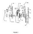
- FIG. 7is a partial exploded view of the FIG. 6A-6B energy harvesting apparatus
- FIG. 8is a schematic block diagram of the FIG. 6A-6B energy harvesting apparatus
- FIG. 9is a schematic block diagram showing a method for determining when to engage the FIG. 6A-6B energy harvesting apparatus to harvest energy under mutualistic conditions according to a particular embodiment of the invention.
- FIG. 10shows a number of plots relating to the harvesting of energy while the host is walking using the FIG. 6A-6B energy harvesting apparatus in accordance with the method of FIG. 9 ;
- FIG. 11is a schematic block diagram showing a method for determining when to engage the FIG. 6A-6B energy harvesting apparatus to harvest energy under mutualistic conditions according to another embodiment of the invention.
- FIG. 12is a schematic block diagram of an energy harvesting apparatus according to another embodiment of the invention.
- FIGS. 13A and 13Bare respectively isometric and exploded isometric views of a bi-directional energy harvesting apparatus according to a particular embodiment of the invention.
- FIG. 14is a schematic block diagram of the FIG. 13A-13B energy harvesting apparatus
- FIG. 15is a schematic block diagram showing a method for determining when to selectively harvest energy using the FIG. 13A-13B energy harvesting apparatus according to a particular embodiment of the invention.
- FIG. 16shows a number of plots relating to the harvesting of energy while the host is walking using the FIG. 13A-13B energy harvesting apparatus in accordance with the method of FIG. 15 ;
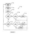
- FIG. 17is a schematic block diagram showing a method for determining when to selectively harvest energy using the FIG. 13A-13B energy harvesting apparatus according to another embodiment of the invention.
- FIG. 18shows a number of plots relating to the harvesting of energy while the host is walking using the FIG. 6A-6B energy harvesting apparatus configured to harvest energy under mutualistic and non-mutualistic conditions;
- FIG. 19is a schematic block diagram showing a method for determining when to selectively harvest energy using the FIG. 4B energy harvesting apparatus according to a particular embodiment of the invention.
- FIG. 20is a schematic block diagram showing a method for determining when to selectively harvest energy using the FIG. 4C energy harvesting apparatus according to a particular embodiment of the invention.
- FIGS. 21A , 21 B and 21 Crespectively depict EMG plots showing muscle activity levels and electrical power generation for a human walking with no energy harvesting, with mutualistic energy harvesting (associated with knee extension only) and with both mutualistic and non-mutualistic energy harvesting (associated with knee extension only); and
- FIG. 22shows a plot of heart rate versus time for a human walking with no energy harvesting, with mutualistic energy harvesting (associated with knee extension only) and with both mutualistic and non-mutualistic energy harvesting (associated with knee extension only).
- FIG. 1Aschematically depicts a positive mechanical power operational mode 10 of a muscle 12 , wherein muscle 12 is used to generate mechanical energy which results in corresponding movement of one or more associated body segment(s) 44 (e.g. limb(s)).
- muscle 12converts chemical energy into mechanical energy of associated body segment 44 . Due to the inefficiency of this conversion process, muscle 12 also outputs heat energy when operating in positive mechanical power mode 10 .
- Positive mechanical power mode 10is associated with the shortening of muscle 12 . Shortening of muscle 12 can pull associated body segment 44 around a joint (not shown), for example.
- the efficiency of positive power productioncan approach 25%. With such an efficiency, for muscle 12 to generate 1 W of mechanical power requires a metabolic cost of 4 W and the remaining 3 W is dissipated as heat.
- FIG. 1Bschematically depicts a negative mechanical power operational mode 20 of muscle 12 , wherein muscle 12 acts to brake (i.e. decelerate) the motion of the associated body segment(s) 44 , thereby reducing the mechanical energy of body segment 44 and causing body segment 44 to decelerate.
- Muscle 12requires chemical energy to cause this braking effect.
- negative mechanical power modemuscle 12 uses chemical energy to reduce the mechanical energy of the associated body segment and, in doing so, produces heat energy.
- Negative mechanical power mode 20is associated activity in a particular muscle 12 when that muscle 12 is lengthening. During negative mechanical power mode, muscle 12 is actively generating force which tends to decelerate a lengthening of muscle 12 .
- associated body segment 44When muscle 12 operates in a negative mechanical power mode, associated body segment 44 may be moving around a joint in a direction that causes muscle 12 to lengthen, but the activity of muscle 12 causes deceleration of the rate of movement of associated body segment 44 .
- the efficiency associated with negative power productioncan be as high as ⁇ 120%. With such an efficiency, for muscle 12 to produce ⁇ 1 W of mechanical power requires a metabolic cost of 0.83 W and 1.83 W is dissipated as heat.
- FIG. 2presents a number of plots representative of various quantities relating to typical dynamics of a knee joint during one full cycle 21 of a walking movement for a 58 kg subject walking at 1.3 m/s with a step frequency of 1.8 Hz:
- cycle 21may generally be divided into a stance phase 21 A, where the foot corresponding to the illustrated knee is on the ground, and a swing phase 21 B, where the foot corresponding to the illustrated knee is off of the ground.
- the leg corresponding to the illustrated kneeextends forwardly from the hip and represents the front one of the two legs.
- the kneebegins to flex in region 22 A as weight is transferred to the corresponding leg.
- region 22 Bthe illustrated knee rebounds and extends slightly during the swing phase of the other leg.
- region 22 Cthe illustrated knee begins to flex again as it prepares for swing phase 21 B.
- cycle 21enters swing phase 21 B and the foot corresponding to the illustrated knee leaves the ground.
- the illustrated kneecontinues to flex in region 22 D.
- region 22 Ethe knee begins to extend again as the corresponding leg swings forwardly again and prepares for another heel strike.
- region 22 Fthe illustrated knee is relatively straight. The knee may extend slightly beyond straight in region 22 F immediately before heel strike which marks the beginning of the next cycle.
- Regions 28 A and 28 B of power plot 28represent regions where at least some of the muscles associated with the illustrated knee are in negative mechanical power modes 20 (see FIG. 1B ).
- region 28 Athe illustrated knee is flexing and the knee extensor muscles are lengthening, but at least the illustrated knee extensor muscles are acting in a negative mechanical power mode 20 to counteract this flexion movement.
- Region 30 A of plot 30shows how the illustrated knee extensor muscles are active during the time associated with region 28 A.
- region 28 Bthe illustrated knee is extending and the knee flexor muscles are extending, but at least the illustrated knee flexor muscles are acting in a negative mechanical power mode 20 to counteract this extension movement.
- Region 32 A of plot 32shows how the illustrated knee flexor muscles are active during the time associated with region 28 B.
- methods and apparatusare provided for selectively harvesting energy from the movement of particular joints when the muscles associated with the particular joints are operating in negative mechanical power modes 20 (i.e. when muscles would normally be active to decelerate movement of the joints).
- Negativeenergy harvesting
- the harvested energyis output as electrical power.
- mutualisticis appropriate because the mechanical power used to generate electric power under mutualistic conditions can come from the decelerating joints and the harvesting of energy under mutualistic conditions actually assists the muscles to decelerate the joints.
- FIG. 3Bschematically illustrates mutualistic energy harvesting 40 when muscle 12 is operating in a negative mechanical power mode 20 .
- muscle 20consumes metabolic (chemical) energy in an effort to reduce the mechanical energy of one or more associated body segment(s) 44 (i.e. cause body segment 44 to decelerate) and outputs heat energy during this process.
- a harvester 42helps to reduce the mechanical energy of associated body segment 44 (i.e. cause body segment 44 to decelerate) by converting the mechanical energy of associated body segment 44 into electrical energy.
- harvester 42Rather than using energy from muscle 12 alone to cause body segment 44 to decelerate, harvester 42 helps to cause body segment 44 to decelerate and in doing so converts mechanical energy to electrical energy. According, mutualistic energy harvesting may actually decrease the metabolic costs associated with decelerating the motion of body segment 44 .
- Harvester 42may comprise a generator, for example, and the mechanical energy required to turn the generator may be obtained from movement of associated body segment 44 as it decelerates.
- selectively harvesting energy in a mutualistic mode 40muscle 12 requires less metabolic (chemical) energy, because part of the negative power required to cause body segment 44 to decelerate is provided by harvester 42 . Accordingly, selectively harvesting energy in a mutualistic mode 40 can actually reduce the metabolic cost and/or effort normally experienced by a person when performing an activity. For example, assuming that harvester 42 has a 50% mechanical to electrical conversion efficiency, then extracting 1 W of electrical power from harvester 42 would require 2 W of mechanical energy, meaning that the mechanical energy reduction performed by muscle 12 would be 2 W less. Assuming that muscle 12 operates with the above-discussed ⁇ 120% efficiency in negative mechanical power mode 20 , then a 2 W reduction in mechanical energy corresponds approximately to a 1.7 W reduction in metabolic (chemical) energy consumed by muscle 12 .
- energy harvesting methods and apparatusalso harvest energy from the movement of particular joints when the muscles associated with the particular joints are operating in positive mechanical power modes 10 (i.e. when muscles are active to generate movement of the body).
- Harvesting energy from the movement of particular joints when the muscles associated with the particular joints are operating in a positive mechanical power mode 20is referred to herein as “non-mutualistic” energy harvesting.
- Non-mutualistic energy harvestinggenerally requires increased metabolic costs (i.e. chemical energy) from the muscles. For this reason, non-mutualistic energy harvesting may also be referred to as “parasitic” energy harvesting.
- FIG. 3Aschematically illustrates non-mutualistic energy harvesting 50 when muscle 12 is operating in a positive mechanical power mode 10 .
- muscle 20consumes metabolic energy in an effort to generate mechanical energy in one or more associated body segment(s) 44 (i.e. to cause body segment(s) 44 to move) and outputs heat energy during this process.
- harvester 42when harvesting energy in a non-mutualistic manner 50 , harvester 42 requires additional mechanical energy generated by muscle 12 and associated with movement of body segment 44 to provide electrical energy.
- non-mutualistic energy harvesting 50requires that the user work harder (i.e.
- methods and apparatuswhich incorporate one or more feedback-providing sensors. Feedback from such sensors can be used to make decisions as to whether particular muscle(s) is/are operating in a negative mechanical power mode 20 , thus permitting selective engagement and disengagement of the generator for mutualistic energy harvesting 40 and for avoiding, to the extent possible, non-mutualistic energy harvesting 50 .
- each walking cycleinvolves:
- FIG. 2also shows another region 28 D at the end of stance phase 21 A and the beginning of swing phase 21 B, where the knee is flexing and exhibits negative power.
- region 28 Drepresents a period of positive mechanical power operation with the muscles associated with the ankle (i.e. movement of the ankle). Some of the ankle muscles (e.g. the gastrocnemius) cross the knee joint. A potential consequence of harvesting energy from knee joint motion in region 28 D is interference with the positive mechanical power operation of these muscles with respect to the ankle joint.
- Harvesting energy in region 28 Dmay be non-mutualistic because of the increase in metabolic cost associated with interfering with the positive power operational mode of the muscles that cross both the ankle and knee joints. In general, it is desirable to consider the function of individual muscles when considering whether to harvest energy.
- FIGS. 4A , 4 B and 4 Cdepict a number of different exemplary embodiments of the invention.
- FIG. 4Ashows a wearable energy harvesting apparatus 60 according to a particular embodiment of the invention.
- harvesting apparatus 60operates to harvest energy from the motion of knee joint 62 and the corresponding knee extensor muscles and knee flexor muscles.
- FIG. 4Bshows an energy harvesting apparatus 70 according to another embodiment of the invention that is embedded in a prosthetic limb 74 .
- prosthetic limb 74incorporates a joint 72 which is intended to emulate a knee joint.
- harvesting apparatus 70operates to harvest energy from the motion of joint 72 .
- FIG. 4Ashows a wearable energy harvesting apparatus 60 according to a particular embodiment of the invention.
- harvesting apparatus 60operates to harvest energy from the motion of knee joint 62 and the corresponding knee extensor muscles and knee flexor muscles.
- FIG. 4Bshows an energy harvesting apparatus 70 according to another embodiment of the invention that is embedded in a prosthetic limb
- FIG. 4Cshows an energy harvesting apparatus 80 according to yet another embodiment of the invention that is implanted under the skin of the host to harvest energy from the motion of ankle joint 82 and its corresponding ankle flexor and extensor muscles (e.g. the tibialis anterior).
- Energy harvesting apparatus 60( FIG. 4A ) can be mounted to and/or worn on the body 61 of a human.
- apparatus 60is mounted across knee joint 62 with an upper component 64 located above knee joint 62 , a lower component 66 located below knee joint 62 and a pivot joint 68 located generally coaxially with knee joint 62 .
- pivot joint 68pivots allowing corresponding relative movement between upper component 64 and lower component 66 .
- Energy harvester 60may be designed to harvest energy during extension of knee joint 62 , during flexion of knee joint 62 or during both extension and flexion.
- energy harvesting apparatuscan be configured to be mounted across other joints, such as the ankle, wrist or elbow, for example. In other embodiments, energy harvesting apparatus may extend across a plurality of joints, such as the knee and the ankle or the elbow and the shoulder for example.
- FIG. 5Ais a schematic block diagram of energy harvesting apparatus 60 according to a particular embodiment of the invention.
- Energy harvesting apparatus 60comprises a transmission 102 which is mechanically connected to the body 61 of a host via a mechanical connection 100 .
- connection 100connects the knee 62 of the host to transmission 102 .
- Connection 100transfers mechanical power (represented by line 112 ) from knee 62 to transmission 102 .
- Connection 100may comprise one or more of upper and lower components 64 , 66 and pivot joint 68 (see FIG. 4A ). In other embodiments, connection 100 may be provided by other suitably configured mechanisms.
- Transmission 102transforms mechanical power 112 received from connection 100 into a different form of mechanical power (represented by line 114 ) suitable for use by generator 104 .
- transmission 102converts relatively high-torque, low-speed mechanical power (e.g. the type of mechanical power produced by knee joint 62 ) into relatively low-torque, high-speed mechanical power which is suitable for use by generator 104 .
- Generator 104converts mechanical power 114 into electrical power signal 116 .
- electrical power signal 116may have a variety of forms.
- energy harvesting apparatus 60comprises a signal conditioner 106 which conditions electrical power signal 116 to generate an electrical power output signal 118 .
- Electrical power output signal 118 output by signal conditioner 106is supplied to an electrical load 111 .
- Electrical load 111may comprise any one or more components capable of using and/or storing electrical power from output signal 118 .
- suitable electric loads 111include electronic devices (e.g. personal electronic devices) and battery chargers.
- Energy harvester 60also comprises a controller 108 which receives a feedback signal 122 from one or more sensors 110 .
- Controller 108may comprise one or more data processors, together with suitable hardware, including, by way of non-limiting example: accessible memory, logic circuitry, drivers, amplifiers, A/D and D/A converters and the like.
- Controller 108may comprise, without limitation, a microprocessor, a computer-on-a-chip, the CPU of a computer or any other suitable microcontroller.
- Controller 108may comprise a plurality of data processors.
- Feedback signal 122preferably provides controller 108 with information that may be used by controller 108 to determine whether or not conditions are suitable for mutualistic energy harvesting.
- Sensor(s) 110may comprise a wide variety of sensors and may detect, by way of non-limiting example, positions of the body of the host (e.g. one or more limbs or other body segments), positions and/or activity levels of muscles, positions and/or configurations of generator 104 , transmission 102 and/or connection 100 .
- Non-limiting examples of sensor(s) which may be suitable for sensor(s) 110include potentiometers, accelerometers, rate gyroscopes, position encoders, inclinometers, pressure sensors or the like that detect contact of a body segment with another object (e.g. the ground).
- Sensor(s) 110may comprise signal conditioning circuitry (not shown) that is well known to those skilled in the art for providing a signal suitable for use by controller 108 .
- signal conditioning circuitrymay comprise amplifiers, analog to digital A/D converters, filters and the like.
- Controller 108may make use of the information contained in feedback signal 122 to determine whether or not conditions are suitable for mutualistic energy harvesting.
- controller 108is configured, or may be configured (e.g. by user input), to cause harvester 60 to harvest energy primarily under conditions considered by controller 108 to be mutualistic.
- controller 108couples body 61 (e.g. knee 62 ) to electrical load 111 under conditions which controller 108 determines to be mutualistic and disengages body 61 (e.g. knee 62 ) from electrical load 111 under conditions which controller 108 determines to be non-mutualistic.
- Controller 108may use a wide variety of techniques to couple body 61 to electrical load 111 under mutualistic conditions and/or decouple body 61 from electrical load 111 under non-mutualistic conditions.
- Techniques for coupling body 61 to, and decoupling body 61 from, load 111can involve mechanical coupling/decoupling.
- controller 108may use signal 120 A to cause connection 100 to be mechanically coupled to body 61 under mutualistic conditions and to cause connection 100 to be mechanically decoupled from body 61 under non-mutualistic conditions.
- Controller 108may additionally or alternatively use signal 120 A and/or signal 120 B to control the operation of connection 100 and/or transmission 102 , such that connection 100 and transmission 102 are mechanically coupled to one another under mutualistic conditions and are mechanically decoupled from one another under non-mutualistic conditions. Controller 108 may additionally or alternatively use signal 120 B and/or signal 120 C to control the operation of transmission 102 and/or generator 104 , such that transmission 102 and generator 104 are mechanically coupled to one another under mutualistic conditions and are mechanically decoupled from one another under non-mutualistic conditions.
- such mechanical coupling and decouplinge.g.
- connection 100 and transmission 102 and/or between transmission 102 and generator 104may be accomplished using a suitably configured clutch which is responsive to one or more of signals 120 A, 120 B, 120 C or a suitably configured locking mechanism that is responsive to one or more of signals 120 A, 120 B, 120 C.
- controller 108may additionally or alternatively use electrical coupling/decoupling mechanisms for coupling body 61 to, and decoupling body 61 from, load 111 .
- controller 108may use signal 120 C and/or signal 120 D to electrically connect generator 104 to conditioning circuitry 106 under mutualistic conditions and to electrically disconnect generator 104 from conditioning circuitry 106 under non-mutualistic conditions.
- Controller 108may additionally or alternatively use signal 120 D to electrically connect conditioning circuitry 106 to electrical load 111 under mutualistic conditions and to electrically disconnect conditioning circuitry 106 from electrical load 111 under non-mutualistic conditions.
- such electrical coupling and decouplingmay be accomplished using a suitably configured electrical switch which is responsive to one or more of signals 120 C, 120 D.
- controller 108is configured, or may be configured (e.g. by user input), to cause harvesters 60 to harvest energy under mutualistic and non-mutualistic conditions. Where it is desired to continually harvest energy under mutualistic and non-mutualistic conditions, controller 108 and sensors 110 are not generally required.
- signals 120 A, 120 B and/or 120 Cmay be used by controller 108 to control other aspects of the operation of connection 100 , transmission 102 and/or generator 104 . Controller 108 may also optionally control the operation of signal conditioner 106 using signal 120 D.
- signals 120 A, 120 B, 120 C, 120 Dcomprise one way signals, but, in other embodiments, signals 120 A, 120 B, 120 C, 120 D comprise two-way signals.
- controller 108is configured, or may be configured (e.g. by user input), to turn off harvester 60 (i.e. so that harvester 60 stops harvesting activity altogether until it is activated again).
- FIG. 5Bis a schematic block diagram showing a method 45 for determining when to engage the FIG. 5A energy harvesting apparatus to harvest energy under mutualistic conditions according to a particular embodiment of the invention.
- Method 45begins in block 47 where controller 108 obtains feedback 122 from sensor(s) 110 .
- controller 108makes use of feedback data 122 (which may include present and historical feedback data 122 ) to make a decision as to whether conditions are mutualistic such that energy should be harvested.
- method 45involves processing feedback data 122 .
- the block 49 processingmay comprise filtering, scaling, offsetting or otherwise digitally manipulating the incoming angular position data, for example. In some embodiments, some of the block 49 processing may occur in the analog domain (i.e. prior to the block 47 data acquisition).
- Block 51involves an inquiry into whether or not controller 108 considers the conditions to be mutualistic.
- the block 51 inquirycomprises considering a model of the motion associated with one or more joints (e.g. knee 62 ) and using the model together with measured characteristics associated with the one or more joints (e.g. feedback data 122 ) to determine whether conditions are mutualistic.
- the block 51 inquiryadditionally or alternatively comprises direct measurement or sensing of muscle activity to determine whether conditions are mutualistic.
- the block 51 inquirymay comprise assessing whether: (i) one or more muscles associated with the one or more joints are acting to decelerate motion of the one or more joints; (ii) one or more muscles associated with the one or more joints are producing torque in a particular direction and the one or more joints are moving in the opposing direction; (iii) one or more muscles associated with the one or more joints are extending and the same one or more muscles are active; and/or (iv) one or more muscles associated with the one or more joints are otherwise operating in a negative mechanical power operational mode.
- the block 51 inquirymay also involve an optional inquiry into whether there is some reason that controller 108 should not cause energy to be harvested even though conditions appear to be mutualistic. Such an inquiry may involve knowledge of particular types of movement of the one or more joints and/or the one or more associated muscles.
- controller 108may determine, during such an inquiry, that it is not desirable to harvest energy from knee 62 during region 28 D of the walking cycle (see FIG. 2 ) even though one or more muscles associated with knee 62 are operating in a negative mechanical power operational mode.
- negative power operation of some muscles associated with knee motion in region 28 Dmay be accompanied by positive power operation of the same muscles associated with ankle motion.
- controller 108determines in block 51 that conditions are mutualistic (block 51 YES output)
- method 45proceeds to block 53 where controller 108 causes an appropriate one or more of signals 120 A, 120 B, 120 C, 120 D to couple body 61 to electrical load 111 , thereby engaging energy harvesting.
- controller 108determines in block 51 that conditions are non-mutualistic (block 51 NO output)
- method 45proceeds to block 55 where controller 108 causes an appropriate one or more of signals 120 A, 120 B, 120 C, 120 D to decouple body 61 from electrical load 111 , thereby disengaging energy harvesting.
- Method 45then loops back to block 47 .
- FIGS. 6A , 6 B, 7 and 8show an energy harvester 60 A according to another embodiment of the invention.
- energy harvester 60 Ais similar to energy harvester 60 described above and similar reference numerals are used to describe features of energy harvester 60 A that are similar to corresponding features of energy harvester 60 .
- energy harvester 60 Ais connected to knee 62 of the host by connection 100 .
- Energy harvester 60 Ais configured to harvest energy associated with extension of knee 62 only.
- energy harvester 60 Ais configurable to selectively harvest energy under mutualistic conditions when the knee flexor muscles are operating in negative mechanical power mode to decelerate the extension motion of knee 62 .
- Energy harvester 60 Acomprises a connection 100 which transfers mechanical power 112 from knee 62 to transmission 102 .
- connection 100 of energy harvester 60 Acomprises an upper component 64 located above knee 62 and a lower component located below knee 62 which are coupled to one another by a pivot joint 68 that is generally coaxial with knee joint 62 .
- connection 100also comprises upper band 64 A which couples upper component 64 to thigh 67 of the host and lower band 66 A which couples lower component 66 to calf 69 of the host.
- Upper band 64 A and lower band 66 Amay be provided by a single component similar to a orthopedic knee brace, for example.
- connection 100is designed to have a minimal impact on the available range of motion of knee joint 62 .
- connection 100comprises a torque transfer shaft 131 , such that movement of pivot joint 68 in either direction causes corresponding movement of shaft 131 .
- Rotation of torque transfer shaft 131is schematically represented in FIG. 8 by line 112 .
- Transmission 102 of energy harvester 60 Aconverts relatively high-torque, low-speed mechanical power 112 (e.g. the type of mechanical power produced by knee joint 62 (see torque plot 26 of FIG. 2 )) into relatively low-torque, high-speed mechanical power 114 which is suitable for use by generator 104 .
- transmission 102 of energy harvester 60 Acomprises a roller clutch 130 and a gear train 134 .
- roller clutch 130which comprises a mechanical bypass 132 .
- Roller clutch 130is a uni-directional torque transfer mechanism. When shaft 131 rotates in a particular direction corresponding, in this embodiment, to extension of knee joint 62 , roller clutch 130 engages shaft 131 , thereby causing rotation of roller clutch 130 and corresponding rotation of gearing 134 . Conversely, when shaft 131 rotates in the opposing direction corresponding, in this embodiment, to flexion of knee joint 62 , mechanical bypass 132 allows shaft 131 to rotate freely relative to roller clutch 130 .
- the intermittent rotation of roller clutch 130(corresponding to extension of knee joint 62 ) causes corresponding intermittent rotation of gearing 134 with relatively high-torque and relatively low-speed.
- the intermittent rotation of roller clutch 130is represented in FIG. 8 by line 142 .
- Gearing mechanism 134has a relatively high input to output gear ratio, so that relatively high-torque, low-speed mechanical power 142 is converted to relatively high-speed, low-torque mechanical power (represented in FIG. 8 by line 114 ).
- the input to output gearing ratio of gearing mechanism 134may be in a range of 25-500.
- Relatively high-speed, low-torque mechanical power 114 output by gearing mechanism 134is preferably configured (by gearing mechanism 134 ) to provide mechanical power suitable for input to generator 104 .
- Gearing mechanism 134is preferably relatively lightweight and not overly cumbersome.
- the torque/speed conversion function of gearing mechanism 134is implemented by other transmission systems and combinations of transmission systems, such as belt and pulley-based transmission systems, rack and pinion-based transmission systems and the like, for example.
- generator 104can comprise any suitable generator capable of converting mechanical power 114 into electrical power 116 .
- generator 104is relatively lightweight and is not overly cumbersome.
- generator 104comprises a rotary-magnetic brushless DC motor which outputs three phase electrical output power 116 .
- generator 104may comprise any suitably configured generator.
- energy harvester 60 Acomprises a signal conditioner 106 .
- Signal conditioner 106functions generally to condition electrical power signal 116 output from generator 104 to a form suitable for use by electrical load 111 . Accordingly, signal conditioner 106 may take a wide variety of forms and may comprise a wide variety of components, depending on the particulars of generator 104 (and its output power signal 116 ) and depending on the nature of electrical load 111 and its input requirements.
- generator 104comprises a rotary-magnetic brushless DC motor which outputs a three phase electrical power signal 116 and electrical load 111 comprises a rechargeable DC battery which requires a single-phase electrical input signal 118 .
- signal conditioner 106comprises a full wave rectifier 138 and associated power conditioning circuitry 140 .
- Power conditioning circuitry 140may comprise one or more filters to reduce the ripple voltage of signal 146 output from rectifier 138 before providing electrical power output 118 to electrical load 111 .
- signal conditioner 106also comprises a switch 136 , which is controlled by signal 120 D from controller 108 .
- switch 136When switch 136 is closed, electrical power signal 116 from generator 104 is transmitted to rectifier 138 . However, when switch 136 is open, generator 104 is open circuited such that electrical power signal 116 does not reach rectifier 138 . In this manner, when switch 136 is open, electrical load 111 is decoupled from the motion of knee 62 and the resistance to knee motion is reduced.
- Switch 136may generally comprise any switch that is controllable by signal 120 D (e.g. solid state switches, electro-mechanical switches or the like). In one particular embodiment, switch 136 comprises the AQZ202 switch manufactured by Panasonic Corporation.
- controller 108uses feedback signal 122 from sensor(s) 110 to determine whether or not conditions are suitable for mutualistic energy harvesting.
- controller 108sends a signal 120 D which causes switch 136 to be closed and electrical signal 116 from generator 104 to be received by rectifier 138 .
- controller 108sends a signal 120 D which causes switch 136 to open, thereby decoupling electrical load 111 from the motion of knee 62 .
- controller 108uses signal 120 D to control switch 136 thereby causing energy harvester 60 A to selectively harvest energy under mutualistic conditions.
- switch 136represents a means for selectively coupling the movement of knee 62 to, and decoupling the movement of knee 62 from, electrical load 111 in response to a signal from controller 108 .
- energy harvester 60 Amay additionally or alternatively comprise a number of different means for selectively coupling the movement of knee 62 to, and decoupling the movement of knee 62 from, electrical load 111 in response to a signal from controller 108 .
- Such meansmay comprise electrical means, mechanical means and/or electro-mechanical means and such means may be located at various places within energy harvester 60 A.
- controller 108uses feedback signal 122 from sensor(s) 110 to make a decision about whether or not current operating conditions are mutualistic.
- controller 108is configured to implement model-based control. For example, when knee 62 is being used in a repetitive manner (e.g. when walking, running or performing knee bends), the movement of knee 62 can be predicted relatively accurately based on a model.
- a modelmay comprise a known model corresponding to the repetitive movement (e.g. a known model relating to human walking patterns or human knee bend patterns or human cycling patterns).
- Such a modelmay be constructed from previous measurements on the host or on one or more other subjects, for example.
- Controller 108can be programmed or otherwise configured with information relating to one or more models and can use such model(s) in conjunction with feedback signal 122 from sensor(s) 110 to predict whether or not current operating conditions are mutualistic.
- controller 108 of energy harvester 60 Amakes use of such model-based control to determine when conditions are mutualistic.
- energy harvester 60 Ais configured to harvest energy associated with the movement of knee 62 in the extension direction only.
- plots 24 , 26 , 28 and 32show that region 28 B represents a time where: (i) knee 62 is extending (indicated by an angular velocity (plot 24 ) greater than zero); and (ii) the knee flexor muscles are operating in a negative mechanical power mode to decelerate the extension motion of knee 62 (i.e.
- region 28 Brepresents an ideal time for energy harvester 60 A to harvest energy.
- the mechanical power required to turn generator 104actually assists the knee flexor muscles to decelerate the extension of knee 62 (i.e. reducing the effort and/or metabolic cost associated with decelerating the extension of knee 62 ).
- controller 108makes use of feedback signal 122 to help make the decision as to whether conditions are mutualistic.
- sensor(s) 110 of energy harvester 60 Acomprise a potentiometer 113 , which produces a feedback signal 122 representative of the angular position of knee 62 .
- sensor(s) 110 of energy harvester 60 Acomprise a potentiometer 113 , which produces a feedback signal 122 representative of the angular position of knee 62 .
- sensorsmay include optical encoders, magnetic encoders, mechanical encoders, accelerometers and/or rate gyroscopes for example.
- FIG. 9is a block diagram illustrating a method 200 for predicting the existence of mutualistic conditions and for harvesting energy during such mutualistic conditions and disengaging energy harvesting when conditions are non-mutualistic.
- Method 200is suitable for use with energy harvester 60 A of FIGS. 6A , 6 B, 7 and 8 .
- FIG. 10shows a number of plots relating to the harvesting of energy while the host is walking using energy harvester 60 A in accordance with method 200 . Characteristics of the FIG. 10 plots (e.g. the amplitude and frequency) may vary for each individual host and for the conditions being experienced by a particular host.
- Plot 220shows the angle of knee joint 62 of a particular host during a walking motion.
- controller 108may determine the angle of knee joint 62 using feedback signal 122 from sensor(s) 110 (i.e. potentiometer 113 in the illustrated embodiment).
- each cycle 21 of plot 220comprises a stance phase 21 A and a swing phase 21 B.
- Plot 223shows the angular velocity of knee joint 62 .
- the angular velocity plot 223may be obtained by taking the derivative of the angular position plot 220 , for example.
- Method 200 of FIG. 9makes use of model-based control.
- method 200also makes use of sensor(s) which provide information relating to the angular position or other angular characteristics of knee 62 .
- method 200may make use of other sensors that detect one or more characteristics associated with a repetitive motion (e.g. walking).
- such other sensorsmay comprise pressure sensors, which detect heel strike.
- Method 200begins in block 202 , where controller 108 reads feedback signal 122 from angular position sensors 110 .
- controller 108processes the newly acquired sensor information.
- the block 204 processingmay comprise filtering, scaling, offsetting or otherwise digitally manipulating the incoming angular position data, for example. In some embodiments, some of the block 204 processing may occur in the analog domain.
- block 204comprises taking a derivative of the incoming angular position data to obtain data representative of the angular velocity.
- Block 206involves an inquiry into whether the processed sensor data indicates that knee 62 has just begun the swing phase knee extension.
- the swing phase knee extensionis shown as region 22 E of plot 22 ( FIG. 2 ).
- the block 206 inquiryinvolves an inquiry into whether:
- controller 108may conclude that the beginning of the swing phase knee extension occurs whenever the angular velocity crosses zero and the angular position is less than the threshold value ( ⁇ thresh ). In other embodiments, controller 108 may make use of acceleration data (i.e. by taking a second derivative of the angular position data or by directly detecting acceleration data) to assist with determining the beginning of the swing phase knee extension.
- zero accelerationrepresents the transition from stance phase 21 A to swing phase 21 B ( FIG. 10 ).
- sensorsmay be provided to detect other characteristics associated with repetitive motion and such other characteristics may be used to assist with determining the beginning of the swing phase knee extension.
- a pressure sensor placed on the footmay be used to detect the transition from stance phase 21 A to swing phase 21 E. If the start of the swing phase is known (e.g. using an accelerometer or a foot pressure sensor), a delay may be used as a basis for predicting the start of the swing phase knee extension. Such a delay may be based on the frequency of the repetitive motion, for example.
- method 200proceeds to block 210 where a short delay occurs before method 200 proceeds to block 212 .
- the amount of the block 210 delaymay be constant or variable.
- the block 210 delaymay be separately configured (or configurable) for each user.
- the block 210 delaymay be related to the period of the walking cycle 21 of a particular host or to the slope of the terrain.
- the block 210 delaymay be adaptive. By way of non-limiting example, if the period of the walking cycle changes or the slope of the terrain changes, then the block 210 delay may change accordingly.
- the block 210 delaymay be configured to achieve improved performance (e.g. greater power output and/or improved user comfort).
- the block 210 delaycan be set to zero.
- controller 108outputs signal 120 D which causes switch 136 to enter its closed state, where generator 104 is coupled to electrical load 111 and energy harvesting commences. Method 200 then loops back to block 202 , where controller 108 obtains more angular position data from sensors 110 .
- Plot 222 of FIG. 10represents control signal 120 D which, in the illustrated embodiment, is a binary signal having an enable harvest level and a disable harvest level.
- Block 212corresponds to a transition of control signal 120 D from its disable harvest level to its enable harvest level.
- switch 136is closed and the motion of knee 62 is coupled to electrical load 111 , such that electrical power output signal 118 is delivered to load 111 .
- block 208involves determining whether the energy harvesting engaged in block 212 should be discontinued (e.g. because conditions are no longer mutualistic). If energy harvesting is engaged at (or near) the beginning of the swing phase knee extension region 22 E of plot 22 ( FIG. 2 ), then it should be discontinued prior to the commencement of stance phase knee extension region 22 B of plot 22 ( FIG. 2 ). Even if switch 136 is closed, energy harvesting will not occur in region 22 A of plot 22 ( FIG.
- the block 208 inquiry into whether the energy harvesting engaged in block 212 should be discontinuedcomprises an inquiry into whether the processed sensor data indicates that knee 62 has just begun the stance phase knee extension.
- commencement of the stance phase knee extensioncorresponds with the positive-sloped angular velocity zero crossing associated with transition 227 A.
- the block 208 inquiryinvolves an inquiry into whether:
- controller 108may conclude that the beginning of the stance phase knee extension occurs whenever the angular velocity crosses zero and the angular position is greater than the threshold value ( ⁇ thresh ).
- controller 108may make use of acceleration data (i.e. by taking a second derivative of the angular position data or by directly detecting acceleration data) to assist with determining the beginning of the swing phase knee extension.
- zero accelerationrepresents a minimum of the angular velocity that precedes the stance phase knee extension (see FIGS. 2 and 10 ).
- sensorsmay be provided to detect other characteristics associated with repetitive motion and such other characteristics may be used to assist with determining the beginning of the swing phase knee extension.
- a pressure sensor placed on the footmay be used to detect the transition from swing phase 21 B to stance phase 21 A. If either of these conditions (e.g. the angular velocity minimum that precedes the stance phase knee extension or the beginning of the stance phase), a delay may be used as a basis for predicting the start of the stance phase knee extension. Such a delay may be based on the frequency of the repetitive motion, for example.
- block 208 inquiryindicates that stance phase knee extension has not just begun (block 208 NO output) and switch 136 is closed (i.e. energy harvester 60 A is harvesting energy)
- switch 136remains closed and energy harvester 60 A continues to harvest energy while method 200 loops back to block 202 .
- the block 208 inquiryindicates that the stance phase knee extension has just begun (block 208 YES output) and switch 136 is closed (i.e. energy harvester 60 A is harvesting energy)
- method 200proceeds to block 214 where a short delay occurs before method 200 proceeds to block 216 .
- the amount of the block 214 delaymay be constant or variable.
- the block 214 delaymay be separately configured (or configurable) for each user.
- the block 214 delaymay be related to the period of the walking cycle 21 of a particular host or the slope of the terrain on which the host is walking.
- the block 214 delaymay be adaptive. By way of non-limiting example, if the period of the walking cycle or the slope of the terrain changes, then the block 214 delay may change accordingly.
- the block 214 delaymay be configured to achieve improved performance (e.g. greater power output and/or improved user comfort). In some cases, the block 214 delay can be set to zero.
- controller 108outputs signal 120 D which causes switch 136 to enter its open state, where generator 104 is decoupled from electrical load 111 and energy harvesting is discontinued.
- Block 216comprises a transition of control signal 120 D (plot 222 of FIG. 10 ) from its enable harvest level to its disable harvest level.
- switch 136is opened and the motion of knee 62 is decoupled from electrical load 111 .
- method 200again loops back to block 202 .
- block 208 inquiryindicates that stance phase knee extension has not just begun (block 208 NO output) and switch 136 is open (i.e. energy harvester 60 A is not harvesting energy)
- method 200loops back to block 202 without changing the status of switch 136 .
- Plot 224represents the instantaneous power of electrical power output signal 118 . It can be seen by comparing plot 224 and plot 222 that electrical power is only harvested when control signal 120 D (plot 220 ) is at its enable harvest level. As discussed above, control signal 120 D is at its enable harvest level during the swing phase knee extension, when the knee flexor muscles are acting in a negative mechanical power mode to decelerate the extension of knee 62 and conditions are mutualistic.
- Plot 226represents the average power of electrical power output signal 118 (i.e. the average of plot 224 ). In the particular example shown in FIG. 10 , harvester 60 A generates an average power of 2.4 W when the host is walking.
- model-based control similar to that of FIGS. 9 and 10may be used for other cyclical movements.
- Non-limiting examples of such cyclical movementsinclude: running, jumping, knee bends, climbing, ascending and/or descending stairs or embankments, and the like.
- controller 108is configured to directly sense muscle activity to help determine when conditions are mutualistic.
- sensors 110may comprise one or more position sensors for sensing the angle of a joint or other angular characteristics (e.g. angular velocity or acceleration) of a joint (e.g. knee 62 ) and one or more sensors for sensing activity within one or more muscles (e.g. knee flexors). Any of the aforementioned sensors could be used to determine the angular characteristic(s) of the joint.
- Suitable muscle activity sensorsinclude electromyography (EMG) sensors.
- feedback signal 122will contain information relating to the angular characteristic(s), such as position, of knee 62 and muscle activity sensors will be configured (e.g. located) to sense the activity of the knee flexor muscles.
- FIG. 11is a block diagram depicting a method 300 for predicting the existence of mutualistic conditions using muscle activity-based control.
- Method 300is suitable for use with energy harvester 60 A of FIGS. 6A , 6 B, 7 and 8 but may be generalized for use with other embodiments.
- Method 300makes use of one or more position sensor(s) which provide information relating to the angular position of knee 62 and one or more muscle activity sensor(s) which provide information relating to the activity of the knee flexor muscles.
- Method 300begins in block 301 , where controller 108 reads feedback signal 122 from angular position sensor(s) 110 .
- Method 300then proceeds to block 302 , where controller reads feedback signal 122 from muscle activity sensor(s) 110 .
- controller 108processes the newly acquired sensor information.
- the block 304 processingmay comprise filtering, scaling, offsetting or otherwise digitally manipulating the incoming data, for example.
- some of the block 304 processingmay occur in the analog domain (i.e. prior to the block 301 and/or 302 data acquisition).
- block 304comprises taking a derivative of the incoming angular position data to obtain data representative of the angular velocity.
- block 304comprises rectifying and filtering the muscle activity data.
- Method 300then proceeds to block 306 which involves an inquiry as to whether knee 62 is extending.
- the block 306 inquirymay comprise comparing the time derivative of the angular position data (i.e. the angular velocity) to zero. If the angular velocity is greater than zero, then knee 62 is extending and if the angular velocity is less than zero, then knee 62 is flexing.
- the block 306 inquirymay involve looking at historical angular position data to determine if the current angular position is greater than the previous angular position (in which case knee 62 is extending) or if the current angular position is less than the previous angular position (in which case knee 62 is flexing).
- Block 306 inquiryindicates that knee 62 is flexing (block 306 NO output)
- method 300proceeds to block 312 , where harvesting is disabled before looping back to block 301 to collect more data. If on the other hand the block 306 inquiry indicates that knee 62 is extending (block 306 YES output), then method 300 proceeds to block 308 .
- Block 308involves an inquiry into whether the knee flexor muscles are active. Block 308 may involve and inquiry into whether the activity level of the knee flexor muscles is above a certain threshold (I thresh ) in EMG plot 32 of FIG. 2 ).
- method 300proceeds to block 312 , where harvesting is disabled before looping back to block 301 to collect more data. If on the other hand the block 308 inquiry indicates that there is sufficient knee flexor activity (block 308 YES output), then method 300 proceeds to block 310 .
- method 300arrives at block 310 , then knee 62 is extending (block 306 YES output) and the knee flexor muscles are active in trying to decelerate this knee extension (block 308 YES output). Accordingly, the knee flexor muscles are operating in a negative mechanical power mode and conditions are mutualistic.
- controller 108engages harvesting by sending the appropriate control signal 120 D to switch 136 which in turn couples the movement of knee 62 to electrical load 111 .
- method 300may optionally involve delaying for a short period before engaging harvesting in block 310 . The amount of such a delay may be constant or may be separately configured (or configurable) for each user. The delay may be related to the period of the walking cycle 21 of a particular host. The delay may be configured to achieve improved performance (e.g. greater power output and/or improved user comfort). Method 300 then loops back to block 301 to obtain more data.
- FIG. 12is a schematic block diagram of a energy harvesting apparatus 60 B according to another embodiment of the invention.
- Energy harvesting apparatus 60 Bis similar in many respect to energy harvesting apparatus 60 A and similar reference numerals are used to describe features of energy harvester 60 B that are similar to corresponding features of energy harvester 60 A.
- Energy harvester 60 Bdiffers from energy harvester 60 A in that rather than having an electronic switch 136 and a roller clutch 130 , energy harvester 60 B comprises a controllable clutch 150 which mechanically couples the movement of knee 62 to, and decouples the movement of knee 62 from, electrical load 111 .
- Clutch 150comprises a mechanical bypass 152 which is controlled by signal 120 B from controller 108 .
- controller 108decides that conditions are mutualistic and energy should be harvested, controller 108 causes control signal 120 B to engage clutch 150 (i.e. to deactivate mechanical bypass 152 ) which in turn couples the movement of knee 62 to electrical load 111 .
- controller 108decides that conditions are non-mutualistic or that energy should not otherwise be harvested (e.g. because knee 62 is flexing)
- controller 108causes control signal 120 B to disengage clutch 150 (i.e. to activate mechanical bypass 152 ) which in turn decouples the movement of knee 62 from electrical load 111 .
- controllable clutch 150(represented by line 154 ) is an intermittent and variable amplitude mechanical power.
- Energy harvester 60 Balso differs from energy harvester 60 A in that energy harvester 60 B comprises a load leveling mechanism 156 , which receives intermittent and variable amplitude mechanical power 154 from clutch 150 and outputs relatively continuous mechanical power (represented by line 158 ). Relatively continuous mechanical power 158 is delivered to gearing 134 which outputs corresponding mechanical power 114 which may have a different speed and torque that mechanical power 158 .
- Load leveling mechanism 156is not necessary. However, load leveling mechanism 156 may improve the performance of energy harvesting apparatus 60 B because generator 104 may exhibit better performance (i.e. better power conversion efficiency) when input mechanical power 114 is continuous rather than intermittent and variable.
- energy harvester 60 Bis similar to energy harvester 60 A.
- energy harvester 60 Bover energy harvester 60 A is that clutch 150 mechanically disengages gearing 134 and generator 104 from knee 62 .
- clutch 150mechanically disengages gearing 134 and generator 104 from knee 62 .
- energy harvester 60 Arequires that the host move gearing 134 and generator 104 when knee 62 is extending (i.e. roller clutch 130 is engaged) even if switch 136 is open and energy is not being harvested.
- roller clutch 130 of energy harvester 60 Aprovides benefits similar to those of clutch 150 of energy harvester 60 B by mechanically disengaging gearing 134 and generator 104 from knee 62 .
- Energy harvesters 60 A, 60 B described aboveonly harvest energy associated with the extension of knee 62 .
- energy harvesters 60 A, 60 Bcould be modified to only harvest energy associated with the flexion of knee 62 when the energy harvesting conditions are primarily mutualistic. Such energy extraction conditions are exhibited, for example, in region 28 A of plot 28 .
- Energy harvester 60 Acould be modified to harvest the energy associated with knee flexion by reconfiguring roller clutch 130 to engage gearing 134 when knee 62 is flexing and to disengage gearing 134 when knee 62 is extending (see FIG. 8 ).
- Energy harvester 60 Bdoes not require hardware modification to harvest energy during knee extension.
- Method 200may be modified to harvest energy during knee flexion and when the energy harvesting conditions are primarily mutualistic by modifying block 206 and/or block 208 appropriately.
- the block 206 inquirycould be modified to consider whether stance phase 21 A had just begun. It would not be necessary to change the block 208 inquiry. Such modification would allow controller 108 to use method 200 to engage energy harvesting during the time corresponding to region 28 A and to disengage energy harvesting otherwise.
- Method 300may be modified to harvest energy during knee flexion and when the energy harvesting conditions are primarily mutualistic by modifying the block 306 inquiry to consider whether knee 62 is flexing and by modifying the block 308 inquiry to consider whether the knee extensor muscles are active. Such modification would allow controller 108 to use method 300 to engage energy harvesting during the time corresponding to region 28 A and to disengage energy harvesting otherwise.
- energymay be harvested both when knee 62 is extending and when knee 62 is flexing.
- Energy harvesters which can harvest energy during extension and flexionmay be said to be bi-directional.
- FIGS. 13A , 13 B and 14show a bi-directional energy harvesting apparatus 60 C according to another embodiment of the invention.
- Energy harvester 60 Cis configured to harvest energy during knee flexion and during knee extension and primarily when the energy harvesting conditions are mutualistic.
- Energy harvesting apparatus 60 Cis similar in many respects to energy harvesting apparatus 60 A and similar reference numerals are used to describe features of energy harvester 60 C that are similar to corresponding features of energy harvester 60 A.
- Energy harvester 60 Cdiffers from energy harvester 60 A in that energy harvester 60 C comprises a mechanical rectifier 164 which converts both directions of motion of knee joint 62 (i.e. flexion and extension) into a single direction mechanical power signal.
- Mechanical rectifier 164may comprise a pair of uni-directional torque transfer mechanisms 130 , 160 configured in opposing directions with one of the torque transfer mechanisms coupled to a mechanical direction inverter 166 .
- torque transfer mechanisms 130 , 160comprise roller clutches 130 , 160 .
- Roller clutches 130 , 160are configured such that: (i) roller clutch 130 directly engages gearing 134 (as represented by line 142 A) when knee 62 moves in the extension direction and disengages from gearing 134 (via mechanical bypass 132 ) when knee 62 moves in the flexion direction; and (ii) roller clutch 160 engages gearing 134 via direction inverter 166 (as represented by line 142 B) when knee 62 moves in the flexion direction and disengages from gearing 134 (via mechanical bypass 162 ) when knee 62 moves in the extension direction.
- Direction inverter 166(which acts when knee 162 is moving in the flexion direction and roller clutch 160 is engaged), movement of knee 162 in both the flexion direction and the extension direction cause movement of gearing 134 in the same direction.
- Direction inverter 166may be implemented by coupling an additional gear between roller clutch 160 and gearing 134 , for example.
- Those skilled in the artwill appreciate that there are a variety of additional or alternative mechanisms that could be used to implement direction inverter 166 .
- the components of energy harvester 60 Care similar components of energy harvester 60 A.
- controller 108may be configured to cause signal 120 D to close switch 136 (i.e. coupling the motion of knee 62 to load 111 ) when: (i) knee 62 is extending and the energy harvesting conditions are determined by controller 108 to be primarily mutualistic; and/or (ii) knee 62 is flexing and the energy harvesting conditions are determined by controller 108 to be primarily mutualistic.
- region 28 B(of plot 28 ) exhibits mutualistic conditions in swing phase 21 B, where knee 62 is extending and the knee flexor muscles are active to decelerate this extension
- region 28 Aexhibits mutualistic conditions in stance phase 21 A, where knee 62 is flexing and the knee extensor muscles are active to decelerate this flexion.
- Plot 28( FIG. 2 ) also shows that there is a small region 28 C exhibiting non-mutualistic conditions between mutualistic region 28 B and an adjacent mutualistic region 28 A.
- energycould be harvested in region 28 B and region 28 A only.
- the inventorshave determined that it is sometimes convenient to harvest energy from the onset of mutualistic region 28 B, through mutualistic region 28 B, non-mutualistic region 28 C and subsequent mutualistic region 28 A and to discontinue energy harvesting at the conclusion of mutualistic region 28 A. Energy harvesting in region 28 C is non-mutualistic.
- this non-mutualistic energy harvesting in region 28 Cis relatively insignificant in terms of its additional metabolic cost when compared to the metabolic power savings associated with mutualistic energy harvesting in regions 28 A and 28 B.
- energy harvesting in regions 28 A, 28 B and 28 Creduces the frequency of engagement and disengagement of load 111 (which would occur if energy was harvested in regions 28 A and 28 B only) and avoids the possible negative impact of such rapid engagement and disengagement on the coordination of the host.
- controller 108 of energy harvester 60 Cmay make the decision as to when to harvest energy using model-based control techniques or muscle activity-based control techniques so as to harvest energy under mutualistic conditions and to disengage energy harvesting during non-mutualistic conditions.
- FIG. 15is a block diagram illustrating a method 400 for predicting the existence of primarily mutualistic conditions.
- Method 400is suitable for use with energy harvester 60 C of FIGS. 13A , 13 B and 14 .
- FIG. 16shows a number of plots relating to the harvesting of energy while the host is walking using energy harvester 60 C in accordance with method 400 . Characteristics of the FIG. 16 plots (e.g. the amplitude and frequency) may vary for each individual host and for the conditions being experienced by a particular host.
- Plot 420shows the angle of knee joint 62 of a particular host during a walking motion.
- controller 108may determine the angle of knee joint 62 using feedback signal 122 from sensor(s) 110 (i.e. potentiometer 113 in the illustrated embodiment).
- each cycle 21 of plot 402comprises a stance phase 21 A and a swing phase 21 B.
- Plot 423shows the angular velocity of knee joint 62 .
- the angular velocity plot 423may be obtained by taking the derivative of the angular position plot 420 , for example.
- Plot 422represents control signal 120 D which, in the illustrated embodiment, is a binary signal having an enable harvest level and a disable harvest level.
- controller 108When plot 422 is at its enable harvest level, controller 108 outputs a signal 120 D which causes switch 136 to close. When switch 136 is closed, the motion of knee 62 is coupled to electrical load 111 , such that electrical power output signal 118 is delivered to load 111 . When plot 422 is at its disable harvest level, controller 108 outputs a signal 120 D which causes switch 136 to open, thereby decoupling the motion of knee 62 from electrical load 111 and disengaging energy harvesting.
- Method 400makes use of model-based control.
- method 400also makes use of sensor(s) which provide information relating to the angular position (or other angular characteristic(s)) of knee 62 .
- method 400may make use of other sensors that detect one or more characteristics associated with a repetitive motion (e.g. walking).
- model-based control method 400is similar to model-based control method 200 ( FIG. 9 ).
- Blocks 402 , 404 and 406are substantially similar to blocks 202 , 204 and 206 of model-based control method 200 ( FIG. 9 ) and respectively involve reading feedback signal 122 from angular position sensors 110 ; processing the newly acquired sensor information; and conducting an inquiry into whether the processed sensor data indicates that knee 62 has just begun the swing phase knee extension.
- method 400proceeds to block 410 (which imposes a short delay).
- Block 410may be similar to block 210 of method 200 .
- method 400proceeds to block 412 , where controller 108 commences energy harvesting in a manner similar to block 212 of method 200 .
- Method 400then loops back to block 402 , where controller 108 obtains more angular position data from sensors 110 .
- block 408involves determining whether the energy harvesting engaged in block 212 should be discontinued (e.g. because conditions are no longer mutualistic). Block 408 may be substantially similar to block 208 of method 200 .
- Block 408 inquiryindicates that the stance phase knee extension has not just begun (block 408 NO output) and switch 136 is closed (i.e. energy harvester 60 C is harvesting energy), then switch 136 remains closed and energy harvester 60 C continues to harvest energy while method 400 loops back to block 402 .
- the block 408 inquiryindicates that stance phase knee extension has just begun (block 408 YES output) and switch 136 is closed (i.e. energy harvester 60 C is harvesting energy)
- method 400proceeds to delay block 414 .
- Delay block 414may be similar to delay block 214 of method 200 .
- Method 400then proceeds to block 416 , where controller 108 disengages energy harvesting in a manner similar to block 216 of method 200 .
- method 400again loops back to block 402 . If the block 408 inquiry indicates that stance phase knee extension has not just begun (block 408 NO output) and switch 136 is open (i.e. energy harvester 60 C is not harvesting energy), then method 400 loops back to block 402 without changing the status of switch 136 .
- model-based control similar to that of FIGS. 15 and 16may be used for other cyclical movements.
- FIG. 17is a block diagram illustrating a method 500 for predicting the existence of primarily mutualistic conditions suitable for use with energy harvester 60 C of FIGS. 13A , 13 B and 14 using muscle activity-based control.
- Method 500makes use of one or more position sensor(s) which provide information relating to the angular position (or other angular characteristic(s)) of knee 62 and a plurality of muscle activity sensor(s) which provide information relating to the activity of the knee flexor muscles and to the activity of the knee extensor muscles.
- Blocks 501 , 502 and 503 of method 500are similar to blocks 301 , 302 and 303 of method 300 and respectively involve obtaining feedback signal 122 from angular position sensor(s) 110 , obtaining feedback signal 122 from muscle activity sensor(s) 110 ; and processing the newly acquired sensor information.
- Block 506involves an inquiry into whether the knee flexor muscles are active. Block 506 may be performed in a manner similar to block 308 of method 300 . If the block 506 inquiry indicates that there is an insufficient level of activity in the knee flexor muscles (block 506 NO output), then method 500 proceeds to block 520 . On the other hand, if the block 506 inquiry indicates that the knee flexor activity is significant (block 506 YES output), then method 500 proceeds to block 508 .
- Block 508involves an inquiry into whether or not knee 62 is extending.
- the block 508 inquirymay be performed in a manner similar to block 306 of method 300 . If the block 508 inquiry indicates that knee 62 is not extending (block 508 NO output), then method 500 loops back to block 501 to collect more data. If on the other hand the block 508 inquiry indicates that knee 62 is extending (block 508 YES output), then method 500 proceeds to block 510 , where controller 108 engages harvesting before looping back to block 501 to collect more data.
- method 500may optionally involve delaying for a short period before engaging harvesting in block 510 . The amount of such a delay may be constant or may be separately configured (or configurable) for each user. The delay may be related to the period of the walking cycle 21 of a particular host. The delay may be configured to achieve improved performance (e.g. greater power output and/or improved user comfort). Method 500 then loops back to block 501 to obtain more data.
- Block 520involves an inquiry into whether the knee extensor muscles are active. Block 520 may be performed in a manner similar to block 308 of method 300 except that block 520 involves extensor muscles rather than flexor muscles. If the block 520 inquiry indicates that there is an insufficient level of activity in the knee extensor muscles (block 520 NO output), then method 500 loops back to block 501 to collect more data. On the other hand, if the block 520 inquiry indicates that the knee extensor activity is significant (block 520 YES output), then method 500 proceeds to block 514 .
- Block 514involves an inquiry into whether or not knee 62 is flexing.
- the block 514 inquirymay comprise comparing the time derivative of the angular position data (i.e. the angular velocity) to zero. If the angular velocity is less than zero, then knee 62 is flexing.
- the block 306 inquirymay involve looking at historical angular position data to determine if the current angular position is less than the previous angular position (in which case knee 62 is flexing). If the block 514 inquiry indicates that knee 62 is not flexing (block 514 NO output), then method 500 proceeds to block 518 where controller 108 disengages harvesting (if harvesting was engaged) before looping back to block 501 to collect more data. If on the other hand the block 514 inquiry indicates that knee 62 is flexing (block 514 YES output), then method 500 proceeds to block 516 where controller 108 engages harvesting before looping back to block 501 to collect more data.
- FIG. 17shows that energy harvesting is engaged (in block 510 ) when knee 62 is extending (block 508 YES output) and the knee flexor muscles are active to decelerate this extension (block 506 YES output). These conditions correspond to mutualistic region 28 B.
- FIG. 17also shows that energy harvesting is engaged (in block 516 ) when knee 62 is flexing (block 514 YES output) and the knee extensor muscles are active to decelerate this flexion (block 520 YES output). These conditions correspond to mutualistic region 28 A.
- Method 500is configured to engage energy harvesting through regions 28 A, 28 B and 28 C ( FIG. 2 ). After engaging harvesting, method 500 does not disengage harvesting until block 518 .
- Block 518corresponds to the beginning of the stance phase knee extension (i.e. the beginning of region 22 B of plot 22 ( FIG. 2 ) and the end of region 28 A of plot 28 ( FIG. 2 ).
- controller 108can be configured to allow non-mutualistic harvesting.
- controller 108can be configured to output the appropriate signal 120 A, 120 B, 120 C, 120 D to maintain the engagement between the movement of knee 62 and the electrical load 111 .
- the control system for selectively engaging and disengaging energy harvestingis removed from any of the above-described embodiments, such that they harvest energy under mutualistic conditions and non-mutualistic conditions.
- energy harvesting apparatus 60 A( FIG. 8 ) may be configured to harvest energy under mutualistic and non-mutualistic conditions by configuring controller 108 in a suitable manner or by removing controller 108 , switch 136 and/or sensors 110 . When modified in this manner, energy harvester 60 A still only harvest energy when knee 62 is extending, because of roller clutch 130 (i.e. energy harvester is uni-directional).
- FIG. 18shows a number of plots relating to the harvesting of energy while the host is walking using energy harvester 60 A configured to harvest energy under mutualistic and non-mutualistic conditions. Characteristics of the FIG. 18 plots (e.g. amplitude and frequency) may vary for each individual host and for specific conditions being experienced by a particular host.
- Plot 602represents the position of knee 62 (as measured by sensors 110 )
- plot 600represents the instantaneous output power of signal 118
- plot 604represents the average output power of signal 118 .
- FIG. 18shows that during a typical walking cycle 21 energy harvesting occurs during both periods when knee 62 is extending (i.e. when the slope of plot 602 is positive).
- Plot 604indicates that when harvesting under mutualistic and non-mutualistic conditions, the average output power generated at load 111 by energy harvester 60 A is 3.2 W which is greater than the 2.4 W output when harvesting under primarily mutualistic conditions ( FIG. 10 ).
- harvesting energy under non-mutualistic conditionsrequires significant energy input from the host.
- FIGS. 21A , 21 B and 21 Crespectively depict EMG plots showing muscle activity levels and electrical power generation for a human walking
- FIG. 21Adepicts EMG plots 30 for knee extensor muscles and 32 for knee flexor muscles and electrical power plot 902 for a human walking with no energy harvesting.
- FIG. 21Bdepicts EMG plots 904 for knee extensor muscles and 906 for knee flexor muscles and electrical power plot 908 for a human walking with mutualistic energy harvesting associated with knee extension only.
- FIG. 21Cdepicts EMG plots 910 for knee extensor muscles and 912 for knee flexor muscles and electrical power plot 914 for a human walking with both mutualistic and non-mutualistic energy harvesting associated with knee extension only (i.e. when the motion of the knee in the extension direction is always coupled to the electrical load).
- FIG. 22shows a plot of heart rate versus time for a human walking with no energy harvesting (region 916 ), with mutualistic energy harvesting associated with knee extension only (region 918 ) and with both mutualistic and non-mutualistic energy harvesting associated with knee extension only (region 920 ).
- Heart rateis a general indicator of the physical effort involved with an associated activity. Comparing region 916 and region 918 of FIG. 22 shows that less effort is required to walk when harvesting energy under mutualistic conditions (region 918 ) than is required to walk without harvesting energy (region 916 ). Comparing region 920 to regions 916 and 918 of FIG.
- region 920shows that more effort is required to walk when harvesting energy under mutualistic and non-mutualistic conditions (region 920 ) than is required to walk without harvesting energy (region 916 ) or than is required to walk while harvesting energy under mutualistic conditions (region 918 ).
- energy harvesting apparatus 70may be provided as part of, or as an addition to, an orthopedic prosthesis 74 .
- energy harvester 70harvests energy across a joint 72 (or joints) between segments 74 A, 74 B of prosthesis 74 in order to harvest mechanical energy transmitted by joint 72 in much the same manner that any of the above-described energy harvesting apparatus.
- Energy harvester 70may incorporate components that are similar to those of the above-described energy harvesting apparatus.
- Energy harvester 70may be integrated with prosthesis 74 .
- energy harvester 70harvests energy under primarily mutualistic conditions.
- Energy harvester 70may be provided with a control mechanism that permits a user to engage or disengage energy harvesting and/or to change an operational mode of energy harvester 70 .
- energy harvester 70is used in connection with a prosthesis wherein joint 72 is a knee joint ( FIG. 4 ). Knee joints of prosthetic limbs are typically braked (i.e. decelerated) by passive devices, such as hydraulics (e.g. OssurTM Total Knee), or by active devices, such as a Magnetorheologic (MR) Fluid Actuator (e.g. OssurTM Rheo Knee).
- Energy harvester 70uses a generator similar to generator 104 to perform negative work on joint 72 , thereby decelerating the motion of joint 72 . The generator converts this mechanical energy into electrical energy which may be used, in whole or in part, to power electrical components (not shown) of prosthesis 74 . Harvesting energy in this manner can greatly increase the efficiency of prosthesis 74 , allowing for smaller, lighter batteries and longer periods between charges.
- Energy harvester 70may comprise a controller similar to controller 108 which may selectively engage motion of joint 72 to an electrical load under mutualistic conditions.
- Energy harvester 70may comprise one or more sensors (similar to sensors 110 ) to detect the angular position of joint 72 .
- sensorsmay also detect information in respect of an actuator (not shown) acting at joint 72 .
- such sensorsmay detect information, such as current draw for a MR Fluid Actuator or force and velocity signals from a hydraulic actuator, and the controller may use this information to make decisions as to when conditions are mutualistic.
- energy harvester 70is used in the place of the conventional actuator for joint 72 of prosthesis 74 .
- Energy harvester 70may be selectively engaged and disengaged at the correct part of the walking step cycle based on feedback signals related to joint angular velocities, ground reaction force under the prosthetic leg, and information from the intact leg, for example. Exemplarily control logic for an embedded energy harvester is illustrated in FIG. 12 .
- FIG. 19schematically depicts a method 700 for controlling energy harvester 70 so that it will harvest energy during primarily mutualistic conditions.
- Method 700involves reading available sensor data in block 702 and processing the sensor data in block 704 .
- Blocks 706 , 708 , 714 and 720involve using the processed sensor data to make determinations about the direction of motion of joint 72 and the net torque on joint 72 .
- FIG. 19shows that the energy is harvested (block 710 ) when joint 72 is moving in an flexion direction (block 706 YES output) and the net torque on joint 72 is in an extension direction (block 708 YES output).
- energyis harvested (block 716 ) when joint 72 is moving in an extension direction (block 720 YES output) and the net torque on joint 72 is in a flexion direction (block 714 YES output).
- FIG. 4Cdepicts an energy harvesting apparatus 80 according to another embodiment of the invention wherein energy harvesting apparatus 80 is implanted within the body of the host.
- energy harvester 80is placed across the anterior aspect of the ankle joint 82 with an anatomical location similar to that of the tibialis anterior muscle 84 .
- energy harvester 80could be configured to work in conjunction with another joint (or joints) between corresponding body segments.
- Energy harvester 80may be configured to harvest energy in a mutualistic mode and to thereby assist a specific muscle (or group of muscles) during the phases in which the muscle(s) operate in negative mechanical power modes.
- energy harvester 80may be configured to also harvest energy during non-mutualistic modes or to cease energy harvesting altogether. Switching between operational modes may be accomplished by the user, as desired, using a remote switch (not shown), for example.
- implanted energy harvester 80may be similar to those of energy harvesters 60 , 60 A, 60 B, 60 C and 70 described above.
- the generator (not shown) of energy harvester 80comprises a piezoelectric generator to convert mechanical displacement in to electrical energy. In such embodiments, load leveling and gearing may not be required.
- one end of the generatoris attached to the shin bone and the other end to a foot bone. This may be done, for example, using bone screws made of suitable bio-compatible material(s), such as tantalum—a relatively strong material that is not rejected by the body.
- suitable bio-compatible material(s)such as tantalum—a relatively strong material that is not rejected by the body.
- Some of the components of energy harvester 80may be housed in a small implanted hermetic container (not shown).
- the containermay be made, for example, of titanium or some other suitable bio-compatible material.
- the controller of energy harvester 80uses information from suitable sensors to determine when the muscle it is aiding is operating in a negative mechanical power mode.
- a muscleoperates in a negative mechanical power mode when the muscle is lengthening and the muscle is active (i.e trying to contract).
- the velocity of the musclecan be sensed, for example, using accelerometers implanted in the muscle and the activity of the muscle can be sensed, for example, using EMG electrodes implanted in the muscle. Signals from these sensors may be conducted back to the implanted controller by way of suitable conductors such as TeflonTM-coated wires.
- FIG. 20is a schematic block diagram showing a method for determining when to selectively cause energy harvesting apparatus 80 to harvest energy according to a particular embodiment of the invention.
- Method 800senses data (block 802 ) and processes the incoming data (block 804 ).
- Method 800engages harvesting (block 810 ) when the muscle is active (block 806 YES output) and when the associated muscle is lengthening (block 808 YES output). Otherwise harvesting is disengaged (block 812 ).
- the controller of energy harvester 80may be configured to harvest energy when tibialis anterior muscle 84 is active and tibialis anterior muscle 84 is lengthening.
- the resulting electrical energy produced by harvester 80may be used to charge a battery and/or used directly to power another implanted device.
- the electrical powermay be used to charge a small storage battery, such as a lithium-iodine battery, that may be contained within the box that contains the controller.
- energy harvester 80operates as follows.
- the legis in middle of its swing phase, the electrical load is disengaged from movement about the ankle.
- the tibialis anterior muscleis activated which is sensed using one or more muscle activity sensors. This activity in the tibialis anterior muscle meets one condition for engaging energy harvesting.
- the tibialis anterior muscleis lengthened which is sensed using one or more accelerometers or other suitable sensor(s). This lengthening of the tibialis anterior muscle meets the second condition for energy harvesting.
- the controllerthen couples the electrical load to the movement of ankle 82 .
- the sensorsdetect that the tibialis anterior muscle stops lengthening, causing the controller to disengage energy harvesting.
Landscapes
- Engineering & Computer Science (AREA)
- Chemical & Material Sciences (AREA)
- Combustion & Propulsion (AREA)
- Mechanical Engineering (AREA)
- General Engineering & Computer Science (AREA)
- Power Engineering (AREA)
- Health & Medical Sciences (AREA)
- Toxicology (AREA)
- Measurement Of The Respiration, Hearing Ability, Form, And Blood Characteristics Of Living Organisms (AREA)
Abstract
Description
- U.S. Pat. No. 1,472,335 (Luzy);
- U.S. Pat. No. 1,184,056 (Van Deventer);
- U.S. Pat. No. 5,917,310 (Baylis);
- U.S. Pat. No. 5,982,577 (Brown);
- U.S. Pat. No. 6,133,642 (Hutchinson);
- U.S. Pat. No. 6,291,900 (Tiemann et al.).
- Starner, T.,Human-powered wearable computing. IBM Systems Journal, 1996. 35(3-4): 618-629;
- Chapuis, A. and E. Jaquet,The History of the Self-Winding Watch.1956, Geneva: Roto-Sadag S.A.;
- Shenck, N. S. and J. A. Paradiso,Energy scavenging with shoe-mounted piezoelectrics. IEEE Micro, 2001. 21(3): 30-42;
- Kymissis, J., et al.Parasitic Power Harvesting in Shoes. inSecond IEEE International Conference on Wearable Computing.1998: IEEE Computer Society Press;
- Antaki, J. F., et al.,A gait-powered autologous battery charging system for artificial organs. Asaio J, 1995. 41(3): M588-95;
- Gonzalez, J. L., A. Rubio, and F. Moll.A prospect on the use of piezolelectric effect to supply power to wearable electronic devices. in ICMR. 2001. Akita, Japan;
- Moll, F. and A. Rubio.An approach to the analysis of wearable body-powered systems, inMIXDES.2000. Gdynia, Poland;
- Drake, J.,The greatest shoe on earth, inWired.2001. p. 90-100;
- Niu, P., et al.Evaluation of Motions and Actuation Methods for Biomechanical Energy Harvesting. in 35th Annual IEEE Power Electronics Specialists Conference.2004. Aachen, Germany: IEEE.
- U.S. Pat. No. 6,768,246 (Pelrine et al.);
- US patent publication No. US2004/0183306 (Rome);
- U.S. Pat. No. 6,293,771 (Haney et al.);
Plot 22 represents the angle of the knee joint, where 0° represents full extension and negative angles represent knee flexion;plot 24 represents the angular velocity of the knee joint (i.e. the time derivative of plot22), where positive angular velocity represents movement in the knee extension direction and negative angular velocity represents movement in the knee flexion direction;plot 26 represents the moment of the knee joint, where a positive moment represents torque in the extension direction and a negative moment represents torque in the flexion direction;plot 28 represents the mechanical power associated with the knee joint. Mechanical power (plot28) represents the product of the torque (plot26) and the angular velocity (plot24) of the knee joint. The integral of the mechanical power (plot28) represents the mechanical work performed by the knee joint;plot 30 represents rectified and filtered electromyographic (EMG) signals representative of electrical activity generated by the vastus lateralis (i.e. one of the quadricep muscles) which is an example of a knee extensor muscle; andplot 32 represents rectified and filtered EMG signals representative of electrical activity generated by the semitendinosus (i.e. one of the hamstrings) which is an example of a knee flexor muscle.
- a period of time (
region 28A) near the beginning ofstance phase 21A, where the knee is flexing as the weight of the body is being transferred to the corresponding leg and the knee extensor muscles operate in a negative mechanical power mode to receive this weight and decelerate this flexion; and - a period of time (
region 28B) near the end ofswing phase 21B, where the knee is extending and the knee flexor muscles operate in a negative mechanical power mode to decelerate this flexion.
- a period of time (
- (i) the angular velocity crosses zero from a negative value to a positive value (i.e. the angular velocity crosses zero with a positive slope); and
- (ii) the angular position is lower than a threshold value (φthresh).
An angular velocity zero crossing with a positive slope is indicative of a transition from flexion toward extension. However, as shown inFIG. 10 , within each walkingcycle 21, there are twosuch transitions FIG. 10 , the positive-sloped angular velocity zero, crossing associated withtransition 227A has an associated angular position greater than the threshold value (φthresh), meaning that the positive-sloped angular velocity zero crossing associated withtransition 227A does not correspond with the swing phase knee extension. On the other hand, the positive-sloped angular velocity zero crossing associated withtransition 227B has an associated angular position that is less than the threshold value (φthresh), meaning that the positive-sloped angular velocity zero crossing associated withtransition 227B represents the beginning of the swing phase knee extension.
- (i) the angular velocity crosses zero from a negative value to a positive value (i.e. the angular velocity crosses zero with a positive slope); and
- (ii) the angular position is greater than the threshold level (φthresh).
- Some of the embodiments described above involve selectively harvesting energy in a mutualistic mode using the muscles associated with the knee of a human. Those skilled in the art will appreciate that selectively harvesting energy in a mutualistic mode from the muscle(s) associated with other joints is considered to be within the scope of the invention. By way of non-limiting example, one may design similar systems to harvest energy from the muscles associated with movement of an ankle, shoulder, elbow, finger, wrist, neck, hip or the like. Also, energy harvesters according to other embodiments are configured to extract energy from a plurality of joints.
- Some of the embodiments described above involve selective energy harvesting in a mutualistic mode during particular movements, such as walking. In other embodiments, selective energy harvesting in a mutualistic mode may be provided for other types of movements. By way of non-limiting example, such movements may involve knee bends, descending stairs or sloped surfaces, cycling, dancing, typing, throwing or the like.
- In addition to operating in a mutualistic mode, any of the above-discussed electrical energy is harvested at the expense of additional effort required by the host. A benefit of non-mutualistic mode energy harvesting is that there may be more power available for harvesting when compared to mutualistic mode energy harvesting alone.
- The electrical energy generated by any of the above-discussed embodiments may be used in any suitable manner. For example, this electrical energy may be used directly to power electrical devices or this electrical energy may be stored for later use. Non-limiting examples of electrical devices which may be powered by the electrical energy generated by the above-discussed embodiments include orthopedic or neural prosthetic devices, and portable electronic devices (e.g. cellular telephones, personal digital assistants, global positioning system receivers, laptop computers or the like).
- Some of the embodiments described above make use of a roller clutch as a uni-directional torque transfer mechanism. In alternative embodiments, other suitably configured, uni-directional torque transfer mechanisms, such as a ratchet mechanism or the like, may be used in place of a roller clutch.
- Bi-directional energy harvesting apparatus (e.g.
energy harvester 60C ofFIGS. 13A ,13B and14) may be configured to have different gear ratios for flexion and extension. Such different gear ratios may compensate for circumstances where the mechanical power input tends to have different torques and/or different velocities in either direction. - It is not necessary that bi-directional energy harvesting apparatus incorporate a mechanical rectifier. Rectification may be performed in the electrical domain. For example,
uni-directional energy harvester 60A may be made bi-directional by simply removingroller clutch 130 and modifyingrectifier 138 to accommodate bidirectional electrical output fromgenerator 104. - Bi-directional
energy harvesting apparatus 60C (FIG. 14 ) is described as having aelectronic switch 136 for coupling thebody 61 of the host toelectrical load 111 and for decoupling thebody 61 of the host fromelectrical load 111. In other embodiments,energy harvester 60C comprises a controllable mechanical clutch or the like (similar to clutch150 ifenergy harvester 60B (FIG. 12 ) for coupling thebody 61 of the host toelectrical load 111 and for decoupling thebody 61 of the host fromelectrical load 111. Such a controllable clutch could be located betweenmechanical connection 100 andmechanical rectifier 164 or betweenmechanical rectifier 164 and gearing134, for example.Controller 108 may control such a controllable clutch using acorresponding signal 120B. - Some embodiments may comprise different generator types or different generator components. For example, it may be beneficial to use an electro-active polymer or piezo-electric generator. In some embodiments, the generator may generate electricity in response to linear motions of generator components relative to one another. It may also be beneficial to use two or more generators.
- Some embodiments may comprise different transmission configurations or different transmission components. Gearing may be driven directly (rather than using roller clutches). Mechanisms other than traditional gears may be used to change the torque and speed characteristics of the input mechanical power. Examples of such mechanisms include a capstan drive or lever arm. Other load leveling mechanisms may be used, such as a flywheel, for example. In some embodiments, load levelling and/or gearing are not required. In other embodiments, the gearing serves to decrease the velocity of the input mechanical power, which may be desirable when using certain generators such as piezoelectric generators, for example.
Energy harvesting apparatus leveling mechanism 156 ofenergy harvesting apparatus 60B. For example,energy harvester 60A (FIG. 8 could be modified to provide a load leveling device at line142 (i.e. between roller clutch130 and gearing134, for example. Such load leveling devices could be used to deliver relatively continuous mechanical power to theircorresponding gearing 134 andgenerators 104.- Method400 (
FIG. 15 ) and method500 (FIG. 17 ) describe techniques for harvesting energy associated with knee extension and with knee flexion. Both of these methods involve harvesting energy in the smallnon-mutualistic region 28C of plot28 (seeFIG. 2 ). Either of these methods could be modified to harvest energy only in exclusively mutualistic regions (e.g. regions method 500 could be modified to harvest energy exclusively in mutualistic regions by providing a disengage harvesting block (similar to block518) on the NO output ofblocks - Delays similar to
blocks method 200 may be incorporated into other embodiments. By way of non-limiting example, a similar delay could be inserted betweenblocks FIG. 11 ) and/or betweenblocks method 300 and/or betweenblocks method 300. Delays could similarly be inserted into methods500 (FIG. 17 ),700 (FIG. 19 ),800 (FIG. 20 ) and any other embodiment. - Thresholds used to assess whether conditions are mutualistic or non-mutualistic (e.g. φthreshand Ithresh) may be constant or variable and may also be user configurable. Such thresholds may be related to the slope of the terrain. Such thresholds may be adaptive. By way of non-limiting example, if the slope of the terrain changes or the period of a repetitive motion changes, then the threshold may change accordingly.
- In some embodiments, the electrical coupling between
generator 104 and load118 may comprise a wireless coupling. For example,electrical power signal load 111 equipped with a suitable RF receiver. - The above described embodiments comprise a
controller 108. In other embodiments, a other control circuits may be used to provide the functionality ofcontroller 108. Such other control circuits may comprise analog electronic circuitry and/or digital electronic circuitry and may comprises a controller of the type described above. The invention should be understood to include any control circuit capable of performing the functions ofcontroller 108 described above. - An energy harvesting device according to the invention may be built into a garment or made to be worn under or over a garment.
- The embodiments described above relate to harvesting energy from humans, but those skilled in the art will appreciate that energy could be harvested from animals (e.g. livestock) in accordance with the above-described methods and apparatus.
Accordingly, the scope of the invention should be construed in accordance with the substance defined by the following claims.
Claims (20)
Priority Applications (1)
| Application Number | Priority Date | Filing Date | Title |
|---|---|---|---|
| US11/990,165US8299634B2 (en) | 2005-08-10 | 2006-08-10 | Methods and apparatus for harvesting biomechanical energy |
Applications Claiming Priority (3)
| Application Number | Priority Date | Filing Date | Title |
|---|---|---|---|
| US70723205P | 2005-08-10 | 2005-08-10 | |
| PCT/CA2006/001302WO2007016781A1 (en) | 2005-08-10 | 2006-08-10 | Methods and apparatus for harvesting biomechanical energy |
| US11/990,165US8299634B2 (en) | 2005-08-10 | 2006-08-10 | Methods and apparatus for harvesting biomechanical energy |
Related Parent Applications (1)
| Application Number | Title | Priority Date | Filing Date |
|---|---|---|---|
| PCT/CA2006/001302A-371-Of-InternationalWO2007016781A1 (en) | 2005-08-10 | 2006-08-10 | Methods and apparatus for harvesting biomechanical energy |
Related Child Applications (3)
| Application Number | Title | Priority Date | Filing Date |
|---|---|---|---|
| US12/150,671ContinuationUS7659636B2 (en) | 2005-08-10 | 2008-04-30 | Methods and apparatus for harvesting biomechanical energy |
| US12/150,637ContinuationUS7652386B2 (en) | 2005-08-10 | 2008-04-30 | Method and apparatus for harvesting biomechanical energy |
| US13/648,350ContinuationUS8487456B2 (en) | 2005-08-10 | 2012-10-10 | Methods and apparatus for harvesting biomechanical energy |
Publications (2)
| Publication Number | Publication Date |
|---|---|
| US20100276944A1 US20100276944A1 (en) | 2010-11-04 |
| US8299634B2true US8299634B2 (en) | 2012-10-30 |
Family
ID=37727059
Family Applications (5)
| Application Number | Title | Priority Date | Filing Date |
|---|---|---|---|
| US11/990,165Active2028-04-28US8299634B2 (en) | 2005-08-10 | 2006-08-10 | Methods and apparatus for harvesting biomechanical energy |
| US12/150,671Expired - Fee RelatedUS7659636B2 (en) | 2005-08-10 | 2008-04-30 | Methods and apparatus for harvesting biomechanical energy |
| US12/150,637Expired - Fee RelatedUS7652386B2 (en) | 2005-08-10 | 2008-04-30 | Method and apparatus for harvesting biomechanical energy |
| US13/648,350ActiveUS8487456B2 (en) | 2005-08-10 | 2012-10-10 | Methods and apparatus for harvesting biomechanical energy |
| US13/929,542Active2027-01-17US9057361B2 (en) | 2005-08-10 | 2013-06-27 | Methods and apparatus for harvesting biomechanical energy |
Family Applications After (4)
| Application Number | Title | Priority Date | Filing Date |
|---|---|---|---|
| US12/150,671Expired - Fee RelatedUS7659636B2 (en) | 2005-08-10 | 2008-04-30 | Methods and apparatus for harvesting biomechanical energy |
| US12/150,637Expired - Fee RelatedUS7652386B2 (en) | 2005-08-10 | 2008-04-30 | Method and apparatus for harvesting biomechanical energy |
| US13/648,350ActiveUS8487456B2 (en) | 2005-08-10 | 2012-10-10 | Methods and apparatus for harvesting biomechanical energy |
| US13/929,542Active2027-01-17US9057361B2 (en) | 2005-08-10 | 2013-06-27 | Methods and apparatus for harvesting biomechanical energy |
Country Status (6)
| Country | Link |
|---|---|
| US (5) | US8299634B2 (en) |
| EP (1) | EP1946429B1 (en) |
| CN (1) | CN101263641B (en) |
| AU (1) | AU2006279208C1 (en) |
| CA (1) | CA2630198C (en) |
| WO (1) | WO2007016781A1 (en) |
Cited By (22)
| Publication number | Priority date | Publication date | Assignee | Title |
|---|---|---|---|---|
| US8487456B2 (en)* | 2005-08-10 | 2013-07-16 | Bionic Power Inc. | Methods and apparatus for harvesting biomechanical energy |
| CN103615361A (en)* | 2013-10-28 | 2014-03-05 | 华北电力大学(保定) | Running machine energy collection system |
| WO2014176588A3 (en)* | 2013-04-26 | 2015-01-22 | Leto Solutions, Inc. | Prosthetic cooling system |
| US9222468B2 (en) | 2011-09-01 | 2015-12-29 | Bionic Power Inc. | Methods and apparatus for control of biomechanical energy harvesting |
| US9351900B2 (en) | 2012-09-17 | 2016-05-31 | President And Fellows Of Harvard College | Soft exosuit for assistance with human motion |
| US9407125B2 (en) | 2013-06-21 | 2016-08-02 | Queen's University At Kingston | Biomechanical electrical power generation apparatus |
| CN106401886A (en)* | 2016-10-11 | 2017-02-15 | 深圳市华宏昊科技有限公司 | Power generation power structure, wearable power generation device and knee joint protection device |
| US20170070123A1 (en)* | 2015-09-07 | 2017-03-09 | Zhenkun Wang | Farm animal-operated conveyer and generator |
| US10278883B2 (en) | 2014-02-05 | 2019-05-07 | President And Fellows Of Harvard College | Systems, methods, and devices for assisting walking for developmentally-delayed toddlers |
| US20190140517A1 (en)* | 2018-10-07 | 2019-05-09 | Rising Star Pathway, a California Corporation | Processor controlled energy harvester system |
| US10345758B2 (en)* | 2018-10-07 | 2019-07-09 | Rising Star Pathway, a California Corporation | Processor controlled energy harvester based on oscillating weight type energy collectors |
| US10434030B2 (en) | 2014-09-19 | 2019-10-08 | President And Fellows Of Harvard College | Soft exosuit for assistance with human motion |
| US20190339649A1 (en)* | 2018-10-07 | 2019-11-07 | Rising Star Pathway, a California Corporation | Processor controlled energy harvester system optimized for mobile platforms |
| US10843332B2 (en) | 2013-05-31 | 2020-11-24 | President And Fellow Of Harvard College | Soft exosuit for assistance with human motion |
| US10864100B2 (en) | 2014-04-10 | 2020-12-15 | President And Fellows Of Harvard College | Orthopedic device including protruding members |
| US11014804B2 (en) | 2017-03-14 | 2021-05-25 | President And Fellows Of Harvard College | Systems and methods for fabricating 3D soft microstructures |
| US11324655B2 (en) | 2013-12-09 | 2022-05-10 | Trustees Of Boston University | Assistive flexible suits, flexible suit systems, and methods for making and control thereof to assist human mobility |
| US11498203B2 (en) | 2016-07-22 | 2022-11-15 | President And Fellows Of Harvard College | Controls optimization for wearable systems |
| US11508900B2 (en) | 2019-11-26 | 2022-11-22 | The Chinese University Of Hong Kong | Human joint energy harvesting apparatus and wearable electronic device comprising the same |
| WO2022248049A1 (en) | 2021-05-27 | 2022-12-01 | Tino Tech J.D.O.O. | Energy harvesting wearable device |
| WO2022248048A1 (en) | 2021-05-27 | 2022-12-01 | Tino Tech J.D.O.O. | Energy harvesting wearable device |
| US11590046B2 (en) | 2016-03-13 | 2023-02-28 | President And Fellows Of Harvard College | Flexible members for anchoring to the body |
Families Citing this family (132)
| Publication number | Priority date | Publication date | Assignee | Title |
|---|---|---|---|---|
| US20070264564A1 (en) | 2006-03-16 | 2007-11-15 | Infinite Power Solutions, Inc. | Thin film battery on an integrated circuit or circuit board and method thereof |
| US7993773B2 (en) | 2002-08-09 | 2011-08-09 | Infinite Power Solutions, Inc. | Electrochemical apparatus with barrier layer protected substrate |
| US7645246B2 (en)* | 2004-08-11 | 2010-01-12 | Omnitek Partners Llc | Method for generating power across a joint of the body during a locomotion cycle |
| PL1874239T3 (en) | 2005-04-13 | 2014-10-31 | Univ California | Semi-powered lower extremity exoskeleton |
| US7485152B2 (en)* | 2005-08-26 | 2009-02-03 | The Ohio Willow Wood Company | Prosthetic leg having electronically controlled prosthetic knee with regenerative braking feature |
| AU2007223733B2 (en) | 2006-03-09 | 2013-01-10 | The Regents Of The University Of California | Power generating leg |
| DE102006021802A1 (en) | 2006-05-09 | 2007-11-15 | Otto Bock Healthcare Ip Gmbh & Co. Kg | Control of a passive prosthetic knee joint with adjustable damping |
| US8771370B2 (en)* | 2006-12-13 | 2014-07-08 | Otto Bock Healthcare Gmbh | Orthopedic device |
| DE102006059206B4 (en)* | 2006-12-13 | 2010-12-30 | Otto Bock Healthcare Gmbh | Orthopedic device |
| AU2007333874B2 (en) | 2006-12-14 | 2013-07-18 | Lightning Packs Llc | Suspended load ergonomic backpack |
| US7847421B2 (en) | 2007-01-19 | 2010-12-07 | Willowview Systems, Inc. | System for generating electrical energy from ambient motion |
| US20080200963A1 (en)* | 2007-02-15 | 2008-08-21 | Benjamin Pless | Implantable power generator |
| CA2680681C (en)* | 2007-03-29 | 2016-02-16 | Lightning Packs Llc | Backpack based system for human electricity generation and use when off the electric grid |
| US7993291B2 (en)* | 2007-05-29 | 2011-08-09 | Microsoft Corporation | Haptic support and virtual activity monitor |
| DE102007053389A1 (en)* | 2007-11-07 | 2009-05-20 | Otto Bock Healthcare Ip Gmbh & Co. | Method for controlling an orthopedic joint |
| US8217523B2 (en)* | 2007-12-07 | 2012-07-10 | Veryst Engineering Llc | Apparatus for in vivo energy harvesting |
| US9334557B2 (en) | 2007-12-21 | 2016-05-10 | Sapurast Research Llc | Method for sputter targets for electrolyte films |
| JP5705549B2 (en) | 2008-01-11 | 2015-04-22 | インフィニット パワー ソリューションズ, インコーポレイテッド | Thin film encapsulation for thin film batteries and other devices |
| WO2009108705A1 (en)* | 2008-02-25 | 2009-09-03 | Autonomic Technologies, Inc. | Devices, methods, and systems for harvesting energy in the body |
| US9351855B2 (en) | 2008-06-16 | 2016-05-31 | Ekso Bionics, Inc. | Powered lower extremity orthotic and method of operation |
| AU2009269892B2 (en) | 2008-06-16 | 2014-05-08 | Ekso Bionics, Inc. | Semi-actuated transfemoral prosthetic knee |
| WO2010019577A1 (en) | 2008-08-11 | 2010-02-18 | Infinite Power Solutions, Inc. | Energy device with integral collector surface for electromagnetic energy harvesting and method thereof |
| US8283793B2 (en)* | 2008-08-21 | 2012-10-09 | Autonomic Technologies, Inc. | Device for energy harvesting within a vessel |
| WO2010042601A1 (en)* | 2008-10-08 | 2010-04-15 | Infinite Power Solutions, Inc. | Foot-powered footwear-embedded sensor-transceiver |
| US10124205B2 (en) | 2016-03-14 | 2018-11-13 | Tau Orthopedics, Llc | Toning garment with modular resistance unit docking platforms |
| US9327156B2 (en) | 2009-06-19 | 2016-05-03 | Tau Orthopedics, Llc | Bidirectional, neutral bias toning garment |
| US9433814B2 (en) | 2009-06-19 | 2016-09-06 | Tau Orthopedics, Llc | Toning garment with integrated damper |
| US8986177B2 (en) | 2009-06-19 | 2015-03-24 | Tau Orthopedics, Llc | Low profile passive exercise garment |
| US10004937B2 (en)* | 2009-06-19 | 2018-06-26 | Tau Orthopedics Llc | Wearable modular resistance unit |
| US9656117B2 (en) | 2009-06-19 | 2017-05-23 | Tau Orthopedics, Llc | Wearable resistance garment with power measurement |
| WO2011028825A1 (en) | 2009-09-01 | 2011-03-10 | Infinite Power Solutions, Inc. | Printed circuit board with integrated thin film battery |
| US8716877B2 (en) | 2010-05-14 | 2014-05-06 | Thomas Sugar | Method and apparatus for harvesting energy from ankle motion |
| KR101930561B1 (en) | 2010-06-07 | 2018-12-18 | 사푸라스트 리써치 엘엘씨 | Rechargeable high-density electrochemical device |
| DE102010037626A1 (en) | 2010-09-17 | 2012-03-22 | Arne Hammer | Device for generating electrical energy from non-uniform movement |
| US9571012B2 (en) | 2010-11-22 | 2017-02-14 | Laitram, L.L.C. | Energy-harvesting conveyor belts and methods |
| JP2014525086A (en) | 2011-07-05 | 2014-09-25 | サウジ アラビアン オイル カンパニー | Floor mat system and associated computer media for monitoring and improving employee health and productivity, and computer-implemented methods |
| US9492120B2 (en) | 2011-07-05 | 2016-11-15 | Saudi Arabian Oil Company | Workstation for monitoring and improving health and productivity of employees |
| US10307104B2 (en) | 2011-07-05 | 2019-06-04 | Saudi Arabian Oil Company | Chair pad system and associated, computer medium and computer-implemented methods for monitoring and improving health and productivity of employees |
| US9962083B2 (en) | 2011-07-05 | 2018-05-08 | Saudi Arabian Oil Company | Systems, computer medium and computer-implemented methods for monitoring and improving biomechanical health of employees |
| US10108783B2 (en) | 2011-07-05 | 2018-10-23 | Saudi Arabian Oil Company | Systems, computer medium and computer-implemented methods for monitoring health of employees using mobile devices |
| US9844344B2 (en) | 2011-07-05 | 2017-12-19 | Saudi Arabian Oil Company | Systems and method to monitor health of employee when positioned in association with a workstation |
| US9526455B2 (en) | 2011-07-05 | 2016-12-27 | Saudi Arabian Oil Company | Systems, computer medium and computer-implemented methods for monitoring and improving health and productivity of employees |
| US8872640B2 (en) | 2011-07-05 | 2014-10-28 | Saudi Arabian Oil Company | Systems, computer medium and computer-implemented methods for monitoring health and ergonomic status of drivers of vehicles |
| US9710788B2 (en) | 2011-07-05 | 2017-07-18 | Saudi Arabian Oil Company | Computer mouse system and associated, computer medium and computer-implemented methods for monitoring and improving health and productivity of employees |
| US9256711B2 (en) | 2011-07-05 | 2016-02-09 | Saudi Arabian Oil Company | Systems, computer medium and computer-implemented methods for providing health information to employees via augmented reality display |
| US8696610B2 (en) | 2011-07-21 | 2014-04-15 | Clifford T. Solomon | Magnetorheological medical brace |
| WO2013028914A1 (en)* | 2011-08-23 | 2013-02-28 | Oscilla Power Inc. | Method and device for mechanical energy harvesting |
| GB2507918A (en)* | 2011-08-23 | 2014-05-14 | Oscilla Power Inc | Method and device for mechanical energy harvesting |
| EP2817877A4 (en) | 2012-02-22 | 2016-01-27 | Int Electronic Machines Corp | ENERGY COLLECTION |
| US8698329B2 (en)* | 2012-05-25 | 2014-04-15 | Kcf Technologies, Inc. | Apparatuses and methods for using energy harvesting for variable shock absorption in a prosthetic device |
| US9042596B2 (en) | 2012-06-14 | 2015-05-26 | Medibotics Llc | Willpower watch (TM)—a wearable food consumption monitor |
| US10314492B2 (en) | 2013-05-23 | 2019-06-11 | Medibotics Llc | Wearable spectroscopic sensor to measure food consumption based on interaction between light and the human body |
| US9442100B2 (en) | 2013-12-18 | 2016-09-13 | Medibotics Llc | Caloric intake measuring system using spectroscopic and 3D imaging analysis |
| US9536449B2 (en) | 2013-05-23 | 2017-01-03 | Medibotics Llc | Smart watch and food utensil for monitoring food consumption |
| US9254099B2 (en) | 2013-05-23 | 2016-02-09 | Medibotics Llc | Smart watch and food-imaging member for monitoring food consumption |
| ES2773853T3 (en)* | 2012-06-15 | 2020-07-15 | Univ Vanderbilt | Movement assist device |
| US9322723B2 (en) | 2012-07-10 | 2016-04-26 | General Electric Company | Energy harvesting survey apparatus and method of detecting thermal energy |
| US8922150B1 (en) | 2012-07-18 | 2014-12-30 | The Johns Hopkins University | Differential serial driver |
| US9529385B2 (en) | 2013-05-23 | 2016-12-27 | Medibotics Llc | Smart watch and human-to-computer interface for monitoring food consumption |
| US9333107B2 (en) | 2013-08-15 | 2016-05-10 | Google Inc. | Brace system |
| US20150112495A1 (en)* | 2013-10-22 | 2015-04-23 | Electronics And Telecommunications Research Institute | Apparatus and method for extracting maximum power from energy harvester apparatus |
| KR20150055958A (en)* | 2013-11-14 | 2015-05-22 | 삼성전자주식회사 | Wearable robot and control method for the same |
| US9722472B2 (en) | 2013-12-11 | 2017-08-01 | Saudi Arabian Oil Company | Systems, computer medium and computer-implemented methods for harvesting human energy in the workplace |
| US11876354B2 (en) | 2014-01-15 | 2024-01-16 | Lat Enterprises, Inc. | Wearable and replaceable pouch or skin for holding a portable battery pack |
| US11025075B2 (en) | 2014-10-16 | 2021-06-01 | Lat Enterprises, Inc. | Portable power case with heat-resistant material |
| US10476054B2 (en) | 2014-10-16 | 2019-11-12 | Lat Enterprises, Inc. | Portable battery pack comprising a battery enclosed by a wearable and replaceable pouch or skin |
| US10944140B2 (en) | 2014-01-15 | 2021-03-09 | Lat Enterprises, Inc. | Wearable and replaceable pouch or skin for holding a portable battery pack |
| US11996803B2 (en) | 2014-01-15 | 2024-05-28 | Lat Enterprises, Inc. | Foldable solar panel |
| US12119785B2 (en) | 2014-01-15 | 2024-10-15 | Lat Enterprises, Inc. | Dual voltage solar panel |
| US10727457B2 (en) | 2014-01-15 | 2020-07-28 | Lat Enterprises, Inc. | System for supplying power to a portable battery using at least one solar panel |
| US11462649B2 (en) | 2014-10-16 | 2022-10-04 | Lat Enterprises, Inc. | Portable power case |
| US10991992B2 (en) | 2014-01-15 | 2021-04-27 | Lat Enterprises, Inc. | System for supplying power to a portable battery using at least one solar panel |
| US10531590B2 (en) | 2014-10-16 | 2020-01-07 | Lat Enterprises, Inc. | System for supplying power to at least one power distribution and data hub using a portable battery pack |
| US12088244B2 (en)* | 2014-01-15 | 2024-09-10 | Lat Enterprises, Inc. | System for supplying power to at least one power consuming device using rechargeable battery |
| US11304500B2 (en) | 2014-01-15 | 2022-04-19 | Lat Enterprises, Inc. | Wearable and replaceable pouch or skin for holding a portable battery pack |
| US11302987B2 (en) | 2014-10-16 | 2022-04-12 | Lat Enterprises | Material for dissipating heat from and/or reducing heat signature of electronic devices and clothing |
| US12368409B1 (en) | 2014-01-15 | 2025-07-22 | Lat Enterprises, Inc. | Foldable solar panel |
| US9362803B2 (en)* | 2014-01-22 | 2016-06-07 | Constantinos G Panousis | Human powered generator |
| US9692276B2 (en)* | 2014-02-05 | 2017-06-27 | Strength Companion, LLC | Systems and methods related to coupling an energy harvester to exercise equipment |
| CN104207865B (en)* | 2014-09-18 | 2016-01-13 | 北京大学 | A damping control method for a motor-driven calf prosthesis |
| US12407175B2 (en) | 2014-10-16 | 2025-09-02 | Lat Enterprises, Inc. | Wearable and lightweight portable power case |
| US10616534B2 (en) | 2014-10-16 | 2020-04-07 | Lat Enterprises, Inc. | Personal tactical system and network |
| US11025076B2 (en) | 2014-10-16 | 2021-06-01 | Lat Enterprises, Inc. | Portable power case with lithium iron phosphate battery |
| FR3027970A1 (en)* | 2014-11-04 | 2016-05-06 | Imad Morchid | ENERGY GENERATING DEVICE AND ASSOCIATED ENERGY GENERATING METHOD |
| KR102161310B1 (en)* | 2014-11-26 | 2020-09-29 | 삼성전자주식회사 | Method and apparatus for setting assistant torque |
| US10561881B2 (en) | 2015-03-23 | 2020-02-18 | Tau Orthopedics, Inc. | Dynamic proprioception |
| CN104832383B (en)* | 2015-04-28 | 2018-03-13 | 南京邮电大学 | A kind of joint power generation device |
| US10075046B2 (en)* | 2015-10-14 | 2018-09-11 | Bionic Power Inc. | Steady ratio four-bar linkage for genuflective energy harvesting |
| US10475351B2 (en) | 2015-12-04 | 2019-11-12 | Saudi Arabian Oil Company | Systems, computer medium and methods for management training systems |
| US10642955B2 (en) | 2015-12-04 | 2020-05-05 | Saudi Arabian Oil Company | Devices, methods, and computer medium to provide real time 3D visualization bio-feedback |
| US9889311B2 (en) | 2015-12-04 | 2018-02-13 | Saudi Arabian Oil Company | Systems, protective casings for smartphones, and associated methods to enhance use of an automated external defibrillator (AED) device |
| US10628770B2 (en) | 2015-12-14 | 2020-04-21 | Saudi Arabian Oil Company | Systems and methods for acquiring and employing resiliency data for leadership development |
| US11278004B2 (en)* | 2015-12-15 | 2022-03-22 | Battelle Memorial Institute | Transmitters for animals and methods for transmitting from animals |
| US10195099B2 (en)* | 2016-01-11 | 2019-02-05 | Bionic Power Inc. | Method and system for intermittently assisting body motion |
| US10333298B2 (en)* | 2016-02-19 | 2019-06-25 | Bionic Power Inc. | Method and system for bio-mechanical power management |
| US10118696B1 (en) | 2016-03-31 | 2018-11-06 | Steven M. Hoffberg | Steerable rotating projectile |
| CN105952595A (en)* | 2016-07-06 | 2016-09-21 | 深圳市智携科技有限公司 | Power generation system and human body power generation device |
| US11909206B2 (en)* | 2016-08-09 | 2024-02-20 | Danfoss A/S | Hydraulic systems and components including wireless control technology |
| US10117769B2 (en) | 2016-08-31 | 2018-11-06 | Jay C. Humphrey | Orthopedic knee brace |
| CN106438233B (en)* | 2016-10-31 | 2018-11-23 | 南京邮电大学 | A kind of self-adaptation type joint power generation device |
| CN106481521A (en)* | 2016-12-08 | 2017-03-08 | 张晓春 | Trt |
| CN106685047A (en)* | 2017-01-23 | 2017-05-17 | 郑旭飞 | Knee-joint self-generating and energy storage integrated device |
| US10507351B2 (en)* | 2017-01-26 | 2019-12-17 | The Regents Of The University Of Michigan | Wearable resistive device for functional strength training |
| US12152568B2 (en) | 2017-03-21 | 2024-11-26 | David Talarico | Biomechanical electric generator |
| US10785957B2 (en)* | 2017-12-06 | 2020-09-29 | Trupanion, Inc. | Motion powered pet tracker system and method |
| US10824132B2 (en) | 2017-12-07 | 2020-11-03 | Saudi Arabian Oil Company | Intelligent personal protective equipment |
| EP3723672A1 (en) | 2017-12-12 | 2020-10-21 | Össur Iceland EHF | Powered prosthetic knee with battery recharging during regeneration phase |
| US20190240103A1 (en)* | 2018-02-02 | 2019-08-08 | Bionic Power Inc. | Exoskeletal gait rehabilitation device |
| US11712637B1 (en) | 2018-03-23 | 2023-08-01 | Steven M. Hoffberg | Steerable disk or ball |
| JP7167473B2 (en)* | 2018-04-11 | 2022-11-09 | 株式会社ジェイテクト | motion support system |
| CN108433828A (en)* | 2018-04-25 | 2018-08-24 | 合肥德易电子有限公司 | A kind of wearable support arm device |
| US10291099B1 (en) | 2018-05-03 | 2019-05-14 | R C Huglen | Biomechanical electricity generating assembly including sleeve with leg actuated dynamos |
| US20190363611A1 (en)* | 2018-05-24 | 2019-11-28 | Power Scavengers, LLC | Dynamically configured portable power generation |
| US11337485B2 (en)* | 2018-08-30 | 2022-05-24 | The Government Of The United States, As Represented By The Secretary Of The Army | Wearable planetary gear configuration |
| CN109528362B (en)* | 2018-12-27 | 2024-03-15 | 天衍医疗器材有限公司 | Knee joint prosthesis |
| CN109481096B (en)* | 2018-12-27 | 2024-05-28 | 北京爱康宜诚医疗器材有限公司 | Knee joint prosthesis |
| CN109633689A (en)* | 2019-01-08 | 2019-04-16 | 上海电力学院 | The implanted GPS of self-rechargeable suitable for human body |
| CN109528363B (en)* | 2019-01-31 | 2024-07-26 | 北京爱康宜诚医疗器材有限公司 | Control system and joint prosthesis having the same |
| US11533818B2 (en) | 2019-03-12 | 2022-12-20 | Battelle Memorial Institute | Sensor assemblies and methods for emulating interaction of entities within water systems |
| KR102177754B1 (en)* | 2019-06-18 | 2020-11-11 | 한국과학기술연구원 | Legged Robot and Manufacturing Method thereof |
| CN212055004U (en)* | 2019-12-20 | 2020-12-01 | 陈荣文 | Mechanical Energy Harvesting System |
| US11476780B2 (en) | 2020-03-26 | 2022-10-18 | City University Of Hong Kong | Energy harvester and a wearable device |
| KR102322002B1 (en)* | 2020-09-23 | 2021-11-04 | 삼성전자주식회사 | Method and apparatus for setting assistant torque |
| KR102228475B1 (en)* | 2020-09-23 | 2021-03-16 | 삼성전자주식회사 | Method and apparatus for setting assistant torque |
| CN112737213B (en)* | 2021-01-18 | 2022-04-15 | Oppo广东移动通信有限公司 | Electronic equipment and its power supply |
| CN113187684B (en)* | 2021-03-16 | 2023-01-03 | 中国科学院深圳先进技术研究院 | Human walking energy recovery device |
| US20230024676A1 (en) | 2021-07-22 | 2023-01-26 | Gonzalo Fuentes Iriarte | Systems and methods for electric vehicle energy recovery |
| CN113572307B (en)* | 2021-08-24 | 2022-06-10 | 军事科学院系统工程研究院军需工程技术研究所 | Lower limb exoskeleton for energy collection |
| CN113858180B (en)* | 2021-11-05 | 2023-03-10 | 中国科学技术大学 | A magnetorheological joint for lower extremity exoskeleton |
| CN114247101B (en)* | 2022-01-20 | 2022-10-18 | 上海交通职业技术学院 | Step moving counterweight device for table tennis training |
| WO2023144666A1 (en)* | 2022-01-27 | 2023-08-03 | Medtronic, Inc. | Energy harvesting system integrity monitoring |
| TWI890971B (en)* | 2022-12-07 | 2025-07-21 | 宏碁股份有限公司 | Fitness equipment with power generation function |
Citations (89)
| Publication number | Priority date | Publication date | Assignee | Title |
|---|---|---|---|---|
| US1184056A (en) | 1915-07-31 | 1916-05-23 | Harry Randolph Van Deventer | Self-contained generating and lighting unit. |
| US1472335A (en) | 1922-05-01 | 1923-10-30 | Luzy Antoine | Magneto flash light |
| US3358678A (en) | 1964-07-29 | 1967-12-19 | Kultsar Emery | Moving and support system for the human body |
| US3573479A (en) | 1967-11-17 | 1971-04-06 | Harold F Rieth | Generator flashlight |
| US3631542A (en) | 1969-08-11 | 1972-01-04 | Univ Iowa State Res Found | Myoelectric brace |
| US3820168A (en) | 1970-05-01 | 1974-06-28 | Bock O Orthopaedische Ind Fa K | System for operating a prosthetic limb |
| US4065815A (en) | 1976-09-28 | 1978-01-03 | Sen Jung Chen | Hydraulically controlled artificial leg |
| US4569352A (en) | 1983-05-13 | 1986-02-11 | Wright State University | Feedback control system for walking |
| US4697808A (en) | 1985-05-16 | 1987-10-06 | Wright State University | Walking assistance system |
| US4711242A (en) | 1986-02-18 | 1987-12-08 | Wright State University | Control system for knee joint |
| US4760850A (en) | 1986-05-15 | 1988-08-02 | Wright State University | Method for balancing assistance |
| US4781180A (en) | 1986-09-22 | 1988-11-01 | Moshe Solomonow | Orthotic knee brace system and method |
| US4895574A (en)* | 1984-06-06 | 1990-01-23 | Larry Rosenberg | Piezoelectric motivator for prosthetic devices |
| US4953543A (en) | 1988-08-09 | 1990-09-04 | Royce Medical Company | Cruciate ligament leg brace |
| US5062857A (en) | 1990-06-05 | 1991-11-05 | Advanced Prosthestetics Development Corporation | Myoelectrically controlled knee joint locking device |
| US5090138A (en) | 1990-06-11 | 1992-02-25 | Robert Borden | Spring shoe device |
| US5112296A (en) | 1991-04-30 | 1992-05-12 | The Board Of Supervisors Of Louisiana State University | Biofeedback activated orthosis for foot-drop rehabilitation |
| US5133773A (en) | 1988-03-25 | 1992-07-28 | Kabushiki Kaisha Kobe Seiko Sho | Teaching playback swing-phase-controlled above-knee prosthesis |
| US5133774A (en) | 1988-03-25 | 1992-07-28 | Kabushiki Kaisha Kobe Seiko Sho | Teaching playback swing-phase-controlled above-knee prosthesis |
| US5201772A (en) | 1991-01-31 | 1993-04-13 | Maxwell Scott M | System for resisting limb movement |
| US5282460A (en) | 1992-01-06 | 1994-02-01 | Joyce Ann Boldt | Three axis mechanical joint for a power assist device |
| US5344446A (en) | 1988-03-25 | 1994-09-06 | Kabushiki Kaisha Kobe Seiko Sho | Teaching playback swing-phase controlled above-knee prosthesis |
| US5358461A (en) | 1993-08-16 | 1994-10-25 | Bailey Jr Russell M | Exerciser activated body-mounted lights and generators |
| US5443524A (en) | 1992-06-09 | 1995-08-22 | Kabushiki Kaisha Kobe Seiko Sho | Teaching playback swing-phase-controlled above knee prosthesis |
| US5476441A (en) | 1993-09-30 | 1995-12-19 | Massachusetts Institute Of Technology | Controlled-brake orthosis |
| US5616104A (en) | 1995-08-10 | 1997-04-01 | The United States Of America As Represented By The Administrator Of The National Aeronautics And Space Administration | Human powered centrifuge |
| US5628722A (en) | 1995-03-03 | 1997-05-13 | Solomonow; Moshe | Method for maintaining knee stability of a user suffering from damage of a knee ligament |
| US5888213A (en) | 1997-06-06 | 1999-03-30 | Motion Control, Inc. | Method and apparatus for controlling an externally powered prosthesis |
| US5888212A (en) | 1997-06-26 | 1999-03-30 | Mauch, Inc. | Computer controlled hydraulic resistance device for a prosthesis and other apparatus |
| US5893891A (en) | 1993-06-11 | 1999-04-13 | Chas. A. Blatchford & Sons Limited | Prosthesis control system |
| US5917310A (en) | 1995-08-07 | 1999-06-29 | Baylis Generators Limited | Spring operated current generator for supplying controlled electric current to a load |
| US5980435A (en) | 1993-07-09 | 1999-11-09 | Kinetecs, Inc. | Methods of therapy or controlled exercise using a jointed brace |
| US5982577A (en) | 1995-03-31 | 1999-11-09 | Brown; Paul | Batteryless, spring-powered portable cassette player |
| US5992553A (en) | 1997-01-13 | 1999-11-30 | Morrison; Thomas R. | Pedal power sensor and human powered vehicle drive augmentation responsive to cyclic pedal power input |
| US6113642A (en) | 1996-06-27 | 2000-09-05 | Mauch, Inc. | Computer controlled hydraulic resistance device for a prosthesis and other apparatus |
| US6133642A (en) | 1998-11-12 | 2000-10-17 | Freeplay Market Development Limited | Portable electrical power generating system with mechanical and solar power sources |
| US6281594B1 (en) | 1999-07-26 | 2001-08-28 | Ivan Marijan Sarich | Human powered electrical generation system |
| US6291900B1 (en) | 1997-09-15 | 2001-09-18 | General Electric Company | Electrical energy management for manually powered devices |
| US6293771B1 (en) | 1998-10-27 | 2001-09-25 | Thomson Licensing S.A. | Manually-powered apparatus for powering a portable electronic device |
| US20010029400A1 (en) | 2000-01-20 | 2001-10-11 | Deffenbaugh Bruce W. | Electronically controlled prosthetic knee |
| US20010029343A1 (en) | 2000-03-28 | 2001-10-11 | Takeshi Seto | Wearable muscular-force supplementing device |
| US6379393B1 (en) | 1998-09-14 | 2002-04-30 | Rutgers, The State University Of New Jersey | Prosthetic, orthotic, and other rehabilitative robotic assistive devices actuated by smart materials |
| US20020052663A1 (en) | 2000-03-29 | 2002-05-02 | Herr Hugh M. | Speed-adaptive and patient-adaptive prosthetic knee |
| US6423098B1 (en) | 1997-12-10 | 2002-07-23 | Biedermann Motech Gmbh | Leg prosthesis with an artificial knee joint provided with an adjustment device |
| US6500138B1 (en) | 2000-04-07 | 2002-12-31 | Mayo Foundation For Medical Education And Research | Electromechanical joint control device with wrap spring clutch |
| US6517585B1 (en) | 1997-08-15 | 2003-02-11 | Chas. A. Blatchford & Sons Limited | Lower limb prosthesis |
| US6517503B1 (en) | 1998-09-18 | 2003-02-11 | Becker Orthopedic Appliance Company | Orthosis knee joint |
| US20030170599A1 (en) | 2001-01-26 | 2003-09-11 | Monroe Hart | Method and apparatus for providing golf instruction |
| US6645252B2 (en) | 2001-01-26 | 2003-11-11 | Honda Giken Kogyo Kabushiki Kaisha | Drive unit for prosthetic limb |
| US6673117B1 (en) | 2000-11-30 | 2004-01-06 | Adam Soss | Single axis knee joint assembly |
| US20040049290A1 (en) | 2002-08-22 | 2004-03-11 | Stephane Bedard | Control system and method for controlling an actuated prosthesis |
| US20040059433A1 (en) | 2002-09-20 | 2004-03-25 | Slemker Tracy C. | Prosthetic knee-joint assembly including adjustable proximal and/or distal couplings |
| US20040064195A1 (en) | 2002-07-15 | 2004-04-01 | Hugh Herr | Variable-mechanical-impedance artificial legs |
| US6719806B1 (en) | 1998-03-04 | 2004-04-13 | Chas. A. Blatchford & Sons Limited | Lower limb prosthesis and control unit |
| US20040072657A1 (en) | 2002-10-15 | 2004-04-15 | Arguilez Arcadio C. | Tandem exerciser and power generator |
| US20040088057A1 (en) | 2002-08-22 | 2004-05-06 | Stephane Bedard | Positioning of lower extremities artificial proprioceptors |
| US6755870B1 (en) | 1998-12-24 | 2004-06-29 | Biedermann Motech Gmbh | Leg prosthesis with an artificial knee joint and method for controlling a leg prosthesis |
| US6768246B2 (en) | 2000-02-23 | 2004-07-27 | Sri International | Biologically powered electroactive polymer generators |
| US20040183306A1 (en) | 2003-03-17 | 2004-09-23 | Rome Lawrence C | Backpack for harvesting electrical energy during walking and for minimizing shoulder strain |
| US20040186591A1 (en) | 2003-03-20 | 2004-09-23 | Chas. A. Blatchford & Sons Limited | Prosthetic knee joint mechanism |
| US6852131B1 (en) | 2003-08-18 | 2005-02-08 | Chien-Liang Chen | Artificial knee joint with a push rod biased to rotate a prosthetic lower leg rapidly to align with a residual thigh |
| US6911050B2 (en) | 2002-10-23 | 2005-06-28 | Joseph L. Molino | Prosthetic knee unit |
| US20050184878A1 (en) | 2004-02-24 | 2005-08-25 | Dr. Kevin Grold | Body force alarming apparatus and method |
| US6955692B2 (en) | 2003-02-17 | 2005-10-18 | Eska Implants Gmbh & Co. | Leg prosthesis |
| US6966882B2 (en)* | 2002-11-25 | 2005-11-22 | Tibion Corporation | Active muscle assistance device and method |
| US20060046908A1 (en) | 2004-08-11 | 2006-03-02 | Rastegar Jahangir S | Methods and devices for selective exercising of muscles |
| US20060046909A1 (en) | 2004-08-11 | 2006-03-02 | Rastegar Jahangir S | Walk-assist devices and methods |
| US20060046907A1 (en) | 2004-08-11 | 2006-03-02 | Rastegar Jahangir S | Power generation devices and methods |
| US20060046910A1 (en) | 2004-08-11 | 2006-03-02 | Rastegar Jahangir S | Methods and devices for reducing stance energy for rehabilitation and to enhance physical performance |
| US20060069448A1 (en) | 2002-08-30 | 2006-03-30 | Honda Giken Kogyo Kabushiki Kaisha | Joint device for artificial leg, method and control unit for controlling the joint device |
| US7029500B2 (en) | 2002-04-12 | 2006-04-18 | James Jay Martin | Electronically controlled prosthetic system |
| US7045910B2 (en) | 2003-04-01 | 2006-05-16 | Shimano, Inc. | Bicycle power supply with reduced battery leakage |
| US7056297B2 (en) | 2001-12-28 | 2006-06-06 | Matsushita Electric Works, Ltd. | Wearable human motion applicator |
| US20060249315A1 (en) | 2005-03-31 | 2006-11-09 | Massachusetts Institute Of Technology | Artificial human limbs and joints employing actuators, springs, and variable-damper elements |
| US20060260620A1 (en) | 2005-01-18 | 2006-11-23 | The Regents Of University Of California | Lower extremity exoskeleton |
| US20070016329A1 (en) | 2005-03-31 | 2007-01-18 | Massachusetts Institute Of Technology | Biomimetic motion and balance controllers for use in prosthetics, orthotics and robotics |
| US20070043449A1 (en) | 2005-03-31 | 2007-02-22 | Massachusetts Institute Of Technology | Artificial ankle-foot system with spring, variable-damping, and series-elastic actuator components |
| US20070050044A1 (en) | 2005-08-26 | 2007-03-01 | The Ohio Willow Wood Company | Prosthetic leg having electronically controlled prosthetic knee with regenerative braking feature |
| US20070056592A1 (en) | 2005-04-13 | 2007-03-15 | The Regents Of University Of California | Semi-powered lower extremity exoskeleton |
| US20070233279A1 (en) | 2006-03-09 | 2007-10-04 | The Regents Of The University Of California | Power generating leg |
| US7304398B1 (en) | 2006-05-30 | 2007-12-04 | Hyun Bong Kim | Spring activated energy transducer generating A/C electricity from natural forces-frictionless magnetic plate |
| US7367958B2 (en) | 2002-11-21 | 2008-05-06 | Massachusetts Institute Of Technology | Method of using powered orthotic device |
| US7402915B2 (en) | 2003-04-16 | 2008-07-22 | Freeplay Market Development Limited | Pedal generator |
| US7410471B1 (en) | 1998-09-18 | 2008-08-12 | Becker Orthopedic Appliance Company | Orthosis knee joint and sensor |
| US7429253B2 (en)* | 2004-09-21 | 2008-09-30 | Honda Motor Co., Ltd. | Walking assistance system |
| US7431737B2 (en) | 2004-02-12 | 2008-10-07 | össur hf. | System and method for motion-controlled foot unit |
| US20080278028A1 (en)* | 2005-08-10 | 2008-11-13 | Donelan James M | Methods and apparatus for harvesting biomechanical energy |
| US20080288088A1 (en) | 2007-02-06 | 2008-11-20 | Deka Products Limited Partnership | Arm prosthetic device |
| US20090192619A1 (en) | 2007-11-23 | 2009-07-30 | Orthocare Innovations Llc | Passive electro-magnetically damped joint |
Family Cites Families (6)
| Publication number | Priority date | Publication date | Assignee | Title |
|---|---|---|---|---|
| FR2623086B1 (en)* | 1987-11-17 | 1994-03-18 | Adcro Section Ceraval | PROSTHETIC KNEE CONTROLLED BY A MICROPROCESSOR |
| US5383939A (en) | 1991-12-05 | 1995-01-24 | James; Kelvin B. | System for controlling artificial knee joint action in an above knee prosthesis |
| JPH05309109A (en)* | 1992-05-09 | 1993-11-22 | Nabco Ltd | Lower-extremity prosthesis having walking speed control function |
| WO1999005991A2 (en) | 1997-08-01 | 1999-02-11 | Alt Artificial Limb Technology Ltd. | Walk induced energy accumulator |
| US7736394B2 (en)* | 2002-08-22 | 2010-06-15 | Victhom Human Bionics Inc. | Actuated prosthesis for amputees |
| JP5309109B2 (en) | 2010-10-18 | 2013-10-09 | 富士フイルム株式会社 | Medical image processing apparatus and method, and program |
- 2006
- 2006-08-10EPEP06790537.2Apatent/EP1946429B1/enactiveActive
- 2006-08-10CNCN2006800330607Apatent/CN101263641B/ennot_activeExpired - Fee Related
- 2006-08-10AUAU2006279208Apatent/AU2006279208C1/ennot_activeCeased
- 2006-08-10CACA2630198Apatent/CA2630198C/ennot_activeExpired - Fee Related
- 2006-08-10WOPCT/CA2006/001302patent/WO2007016781A1/enactiveApplication Filing
- 2006-08-10USUS11/990,165patent/US8299634B2/enactiveActive
- 2008
- 2008-04-30USUS12/150,671patent/US7659636B2/ennot_activeExpired - Fee Related
- 2008-04-30USUS12/150,637patent/US7652386B2/ennot_activeExpired - Fee Related
- 2012
- 2012-10-10USUS13/648,350patent/US8487456B2/enactiveActive
- 2013
- 2013-06-27USUS13/929,542patent/US9057361B2/enactiveActive
Patent Citations (107)
| Publication number | Priority date | Publication date | Assignee | Title |
|---|---|---|---|---|
| US1184056A (en) | 1915-07-31 | 1916-05-23 | Harry Randolph Van Deventer | Self-contained generating and lighting unit. |
| US1472335A (en) | 1922-05-01 | 1923-10-30 | Luzy Antoine | Magneto flash light |
| US3358678A (en) | 1964-07-29 | 1967-12-19 | Kultsar Emery | Moving and support system for the human body |
| US3573479A (en) | 1967-11-17 | 1971-04-06 | Harold F Rieth | Generator flashlight |
| US3631542A (en) | 1969-08-11 | 1972-01-04 | Univ Iowa State Res Found | Myoelectric brace |
| US3820168A (en) | 1970-05-01 | 1974-06-28 | Bock O Orthopaedische Ind Fa K | System for operating a prosthetic limb |
| US4065815A (en) | 1976-09-28 | 1978-01-03 | Sen Jung Chen | Hydraulically controlled artificial leg |
| US4569352A (en) | 1983-05-13 | 1986-02-11 | Wright State University | Feedback control system for walking |
| US4895574A (en)* | 1984-06-06 | 1990-01-23 | Larry Rosenberg | Piezoelectric motivator for prosthetic devices |
| US4697808A (en) | 1985-05-16 | 1987-10-06 | Wright State University | Walking assistance system |
| US4711242A (en) | 1986-02-18 | 1987-12-08 | Wright State University | Control system for knee joint |
| US4760850A (en) | 1986-05-15 | 1988-08-02 | Wright State University | Method for balancing assistance |
| US4781180A (en) | 1986-09-22 | 1988-11-01 | Moshe Solomonow | Orthotic knee brace system and method |
| US5133774A (en) | 1988-03-25 | 1992-07-28 | Kabushiki Kaisha Kobe Seiko Sho | Teaching playback swing-phase-controlled above-knee prosthesis |
| US5344446A (en) | 1988-03-25 | 1994-09-06 | Kabushiki Kaisha Kobe Seiko Sho | Teaching playback swing-phase controlled above-knee prosthesis |
| US5133773A (en) | 1988-03-25 | 1992-07-28 | Kabushiki Kaisha Kobe Seiko Sho | Teaching playback swing-phase-controlled above-knee prosthesis |
| US4953543A (en) | 1988-08-09 | 1990-09-04 | Royce Medical Company | Cruciate ligament leg brace |
| US5062857A (en) | 1990-06-05 | 1991-11-05 | Advanced Prosthestetics Development Corporation | Myoelectrically controlled knee joint locking device |
| US5090138A (en) | 1990-06-11 | 1992-02-25 | Robert Borden | Spring shoe device |
| US5201772A (en) | 1991-01-31 | 1993-04-13 | Maxwell Scott M | System for resisting limb movement |
| US5112296A (en) | 1991-04-30 | 1992-05-12 | The Board Of Supervisors Of Louisiana State University | Biofeedback activated orthosis for foot-drop rehabilitation |
| US5282460A (en) | 1992-01-06 | 1994-02-01 | Joyce Ann Boldt | Three axis mechanical joint for a power assist device |
| US5443524A (en) | 1992-06-09 | 1995-08-22 | Kabushiki Kaisha Kobe Seiko Sho | Teaching playback swing-phase-controlled above knee prosthesis |
| US5893891A (en) | 1993-06-11 | 1999-04-13 | Chas. A. Blatchford & Sons Limited | Prosthesis control system |
| US5980435A (en) | 1993-07-09 | 1999-11-09 | Kinetecs, Inc. | Methods of therapy or controlled exercise using a jointed brace |
| US5358461A (en) | 1993-08-16 | 1994-10-25 | Bailey Jr Russell M | Exerciser activated body-mounted lights and generators |
| US5476441A (en) | 1993-09-30 | 1995-12-19 | Massachusetts Institute Of Technology | Controlled-brake orthosis |
| US5628722A (en) | 1995-03-03 | 1997-05-13 | Solomonow; Moshe | Method for maintaining knee stability of a user suffering from damage of a knee ligament |
| US5982577A (en) | 1995-03-31 | 1999-11-09 | Brown; Paul | Batteryless, spring-powered portable cassette player |
| US5917310A (en) | 1995-08-07 | 1999-06-29 | Baylis Generators Limited | Spring operated current generator for supplying controlled electric current to a load |
| US5616104A (en) | 1995-08-10 | 1997-04-01 | The United States Of America As Represented By The Administrator Of The National Aeronautics And Space Administration | Human powered centrifuge |
| US6113642A (en) | 1996-06-27 | 2000-09-05 | Mauch, Inc. | Computer controlled hydraulic resistance device for a prosthesis and other apparatus |
| USRE39961E1 (en) | 1996-06-27 | 2007-12-25 | össur hf | Computer controlled hydraulic resistance device for a prosthesis and other apparatus |
| US5992553A (en) | 1997-01-13 | 1999-11-30 | Morrison; Thomas R. | Pedal power sensor and human powered vehicle drive augmentation responsive to cyclic pedal power input |
| US5888213A (en) | 1997-06-06 | 1999-03-30 | Motion Control, Inc. | Method and apparatus for controlling an externally powered prosthesis |
| US5888212A (en) | 1997-06-26 | 1999-03-30 | Mauch, Inc. | Computer controlled hydraulic resistance device for a prosthesis and other apparatus |
| US6517585B1 (en) | 1997-08-15 | 2003-02-11 | Chas. A. Blatchford & Sons Limited | Lower limb prosthesis |
| US6291900B1 (en) | 1997-09-15 | 2001-09-18 | General Electric Company | Electrical energy management for manually powered devices |
| US6423098B1 (en) | 1997-12-10 | 2002-07-23 | Biedermann Motech Gmbh | Leg prosthesis with an artificial knee joint provided with an adjustment device |
| US6719806B1 (en) | 1998-03-04 | 2004-04-13 | Chas. A. Blatchford & Sons Limited | Lower limb prosthesis and control unit |
| US6379393B1 (en) | 1998-09-14 | 2002-04-30 | Rutgers, The State University Of New Jersey | Prosthetic, orthotic, and other rehabilitative robotic assistive devices actuated by smart materials |
| US7410471B1 (en) | 1998-09-18 | 2008-08-12 | Becker Orthopedic Appliance Company | Orthosis knee joint and sensor |
| US6770045B2 (en) | 1998-09-18 | 2004-08-03 | Becker Orthopedic Appliance Company | Orthosis knee joint |
| US6517503B1 (en) | 1998-09-18 | 2003-02-11 | Becker Orthopedic Appliance Company | Orthosis knee joint |
| US6293771B1 (en) | 1998-10-27 | 2001-09-25 | Thomson Licensing S.A. | Manually-powered apparatus for powering a portable electronic device |
| US6133642A (en) | 1998-11-12 | 2000-10-17 | Freeplay Market Development Limited | Portable electrical power generating system with mechanical and solar power sources |
| US6755870B1 (en) | 1998-12-24 | 2004-06-29 | Biedermann Motech Gmbh | Leg prosthesis with an artificial knee joint and method for controlling a leg prosthesis |
| US6281594B1 (en) | 1999-07-26 | 2001-08-28 | Ivan Marijan Sarich | Human powered electrical generation system |
| US20010029400A1 (en) | 2000-01-20 | 2001-10-11 | Deffenbaugh Bruce W. | Electronically controlled prosthetic knee |
| US6764520B2 (en) | 2000-01-20 | 2004-07-20 | Massachusetts Institute Of Technology | Electronically controlled prosthetic knee |
| US6768246B2 (en) | 2000-02-23 | 2004-07-27 | Sri International | Biologically powered electroactive polymer generators |
| US20010029343A1 (en) | 2000-03-28 | 2001-10-11 | Takeshi Seto | Wearable muscular-force supplementing device |
| US6610101B2 (en) | 2000-03-29 | 2003-08-26 | Massachusetts Institute Of Technology | Speed-adaptive and patient-adaptive prosthetic knee |
| US20040039454A1 (en) | 2000-03-29 | 2004-02-26 | Herr Hugh M. | Speed-adaptive and patient-adaptive prosthetic knee |
| US20020052663A1 (en) | 2000-03-29 | 2002-05-02 | Herr Hugh M. | Speed-adaptive and patient-adaptive prosthetic knee |
| US6500138B1 (en) | 2000-04-07 | 2002-12-31 | Mayo Foundation For Medical Education And Research | Electromechanical joint control device with wrap spring clutch |
| US6673117B1 (en) | 2000-11-30 | 2004-01-06 | Adam Soss | Single axis knee joint assembly |
| US6645252B2 (en) | 2001-01-26 | 2003-11-11 | Honda Giken Kogyo Kabushiki Kaisha | Drive unit for prosthetic limb |
| US20030170599A1 (en) | 2001-01-26 | 2003-09-11 | Monroe Hart | Method and apparatus for providing golf instruction |
| US7056297B2 (en) | 2001-12-28 | 2006-06-06 | Matsushita Electric Works, Ltd. | Wearable human motion applicator |
| US7029500B2 (en) | 2002-04-12 | 2006-04-18 | James Jay Martin | Electronically controlled prosthetic system |
| US20060155385A1 (en) | 2002-04-12 | 2006-07-13 | Martin James J | Electronically controlled prosthetic system |
| US20040064195A1 (en) | 2002-07-15 | 2004-04-01 | Hugh Herr | Variable-mechanical-impedance artificial legs |
| US20040049290A1 (en) | 2002-08-22 | 2004-03-11 | Stephane Bedard | Control system and method for controlling an actuated prosthesis |
| US7314490B2 (en) | 2002-08-22 | 2008-01-01 | Victhom Human Bionics Inc. | Actuated leg prosthesis for above-knee amputees |
| US7147667B2 (en) | 2002-08-22 | 2006-12-12 | Victhom Human Bionics Inc. | Control system and method for controlling an actuated prosthesis |
| US7137998B2 (en) | 2002-08-22 | 2006-11-21 | Victhom Human Bionics Inc | Positioning of lower extremities artificial proprioceptors |
| US20040088057A1 (en) | 2002-08-22 | 2004-05-06 | Stephane Bedard | Positioning of lower extremities artificial proprioceptors |
| US20060122710A1 (en) | 2002-08-22 | 2006-06-08 | Stephane Bedard | Control device and system for controlling an actuated prosthesis |
| US20040111163A1 (en) | 2002-08-22 | 2004-06-10 | Stephane Bedard | Actuated leg prosthesis for above-knee amputees |
| US20060069448A1 (en) | 2002-08-30 | 2006-03-30 | Honda Giken Kogyo Kabushiki Kaisha | Joint device for artificial leg, method and control unit for controlling the joint device |
| US20040059433A1 (en) | 2002-09-20 | 2004-03-25 | Slemker Tracy C. | Prosthetic knee-joint assembly including adjustable proximal and/or distal couplings |
| US6910992B2 (en) | 2002-10-15 | 2005-06-28 | Arcadio C. Arguilez | Tandem exerciser and power generator |
| US20040072657A1 (en) | 2002-10-15 | 2004-04-15 | Arguilez Arcadio C. | Tandem exerciser and power generator |
| US6911050B2 (en) | 2002-10-23 | 2005-06-28 | Joseph L. Molino | Prosthetic knee unit |
| US7396337B2 (en) | 2002-11-21 | 2008-07-08 | Massachusetts Institute Of Technology | Powered orthotic device |
| US7367958B2 (en) | 2002-11-21 | 2008-05-06 | Massachusetts Institute Of Technology | Method of using powered orthotic device |
| US6966882B2 (en)* | 2002-11-25 | 2005-11-22 | Tibion Corporation | Active muscle assistance device and method |
| US6955692B2 (en) | 2003-02-17 | 2005-10-18 | Eska Implants Gmbh & Co. | Leg prosthesis |
| US20040183306A1 (en) | 2003-03-17 | 2004-09-23 | Rome Lawrence C | Backpack for harvesting electrical energy during walking and for minimizing shoulder strain |
| US20040186591A1 (en) | 2003-03-20 | 2004-09-23 | Chas. A. Blatchford & Sons Limited | Prosthetic knee joint mechanism |
| US7045910B2 (en) | 2003-04-01 | 2006-05-16 | Shimano, Inc. | Bicycle power supply with reduced battery leakage |
| US7402915B2 (en) | 2003-04-16 | 2008-07-22 | Freeplay Market Development Limited | Pedal generator |
| US6852131B1 (en) | 2003-08-18 | 2005-02-08 | Chien-Liang Chen | Artificial knee joint with a push rod biased to rotate a prosthetic lower leg rapidly to align with a residual thigh |
| US7431737B2 (en) | 2004-02-12 | 2008-10-07 | össur hf. | System and method for motion-controlled foot unit |
| US20050184878A1 (en) | 2004-02-24 | 2005-08-25 | Dr. Kevin Grold | Body force alarming apparatus and method |
| US20060046908A1 (en) | 2004-08-11 | 2006-03-02 | Rastegar Jahangir S | Methods and devices for selective exercising of muscles |
| US7445606B2 (en) | 2004-08-11 | 2008-11-04 | Omnitek Partners Llc | Methods and devices for selective exercising of muscles |
| US20060046909A1 (en) | 2004-08-11 | 2006-03-02 | Rastegar Jahangir S | Walk-assist devices and methods |
| US20060046907A1 (en) | 2004-08-11 | 2006-03-02 | Rastegar Jahangir S | Power generation devices and methods |
| US20060046910A1 (en) | 2004-08-11 | 2006-03-02 | Rastegar Jahangir S | Methods and devices for reducing stance energy for rehabilitation and to enhance physical performance |
| US7429253B2 (en)* | 2004-09-21 | 2008-09-30 | Honda Motor Co., Ltd. | Walking assistance system |
| US20060260620A1 (en) | 2005-01-18 | 2006-11-23 | The Regents Of University Of California | Lower extremity exoskeleton |
| US20070043449A1 (en) | 2005-03-31 | 2007-02-22 | Massachusetts Institute Of Technology | Artificial ankle-foot system with spring, variable-damping, and series-elastic actuator components |
| US20070016329A1 (en) | 2005-03-31 | 2007-01-18 | Massachusetts Institute Of Technology | Biomimetic motion and balance controllers for use in prosthetics, orthotics and robotics |
| US20060249315A1 (en) | 2005-03-31 | 2006-11-09 | Massachusetts Institute Of Technology | Artificial human limbs and joints employing actuators, springs, and variable-damper elements |
| US20070056592A1 (en) | 2005-04-13 | 2007-03-15 | The Regents Of University Of California | Semi-powered lower extremity exoskeleton |
| US20080277943A1 (en)* | 2005-08-10 | 2008-11-13 | Donelan James M | Method and apparatus for harvesting biomechanical energy |
| US7659636B2 (en)* | 2005-08-10 | 2010-02-09 | Bionic Power Inc. | Methods and apparatus for harvesting biomechanical energy |
| US7652386B2 (en)* | 2005-08-10 | 2010-01-26 | Bionic Power Inc. | Method and apparatus for harvesting biomechanical energy |
| US20080278028A1 (en)* | 2005-08-10 | 2008-11-13 | Donelan James M | Methods and apparatus for harvesting biomechanical energy |
| US20070050044A1 (en) | 2005-08-26 | 2007-03-01 | The Ohio Willow Wood Company | Prosthetic leg having electronically controlled prosthetic knee with regenerative braking feature |
| US7485152B2 (en) | 2005-08-26 | 2009-02-03 | The Ohio Willow Wood Company | Prosthetic leg having electronically controlled prosthetic knee with regenerative braking feature |
| US20070233279A1 (en) | 2006-03-09 | 2007-10-04 | The Regents Of The University Of California | Power generating leg |
| US7304398B1 (en) | 2006-05-30 | 2007-12-04 | Hyun Bong Kim | Spring activated energy transducer generating A/C electricity from natural forces-frictionless magnetic plate |
| US20080288088A1 (en) | 2007-02-06 | 2008-11-20 | Deka Products Limited Partnership | Arm prosthetic device |
| US20090192619A1 (en) | 2007-11-23 | 2009-07-30 | Orthocare Innovations Llc | Passive electro-magnetically damped joint |
Non-Patent Citations (33)
| Title |
|---|
| A.L. Hof, et al., "Speed dependence of averaged EMG profiles in walking," Gait & Posture, 2002. 16(1): p. 78-86. |
| B. Hamilton, FAQ: Automotive Gasoline. Retrieved May 12, 2005, from http://www.uvi.edu/Physics/SCI3xxWeb/Energy/GasolineFAQ.html. |
| Brendan I. Koerner, "Rise of the Green Machine," Wired Magazine, 2005. |
| Clive Thompson, "Battery Not Included: Why your laptop is always running out of juice," Slate, 2004. |
| D.A. Winter Biomechanics and motor control of human movement. 2nd ed. 1990, New York: Wiley. xvi, 277. |
| E.R. Nadel and S.R. Bussolari, The Daedalus Project-Physiological Problems and Solutions. American Scientist, 1988, 76(4): p. 351-360. |
| F. Moll and A. Rubio, "An approach to the analysis of wearable body-powered systems," MIXDES 2000, Gdynia, Poland. |
| F.R. Whitt and D.G.Wilson, "Bicycling science," 2nd ed. 1982, Cambridge, Mass.: MIT Press. xviii, 364. |
| G.A. Brooks, T.D. Fahey, & T.P. White, Exercise physiology: human bioenergetics and its applications, 2nd ed. 1996, Mountain View, Calif.: Mayfield Pub. Iii, 750, 4 pages. |
| J. Drake, "The greatest shoe on earth," Wired 2001, p. 90-100. |
| J. Kymissis, et al., "Parasitic Power Harvesting in Shoes," Second IEEE International Conference on Wearable Computing, 1998: IEEE Computer Society Press. |
| J. Maxwell Donelan, et al., "Mechanical and metabolic determinants of the preferred step width in human walking," Proceedings of the Royal Society of London Series B-Biological Sciences, 2001, 268(1480): p. 1985-1992. |
| J. Maxwell Donelan, et al., "Mechanical work for step-to-step transitions is a major determinant of the metabolic cost of human walking," Journal of Experimental Biology, 2002. 205(Pt 23): p. 3717-27. |
| J.F. Antaki, et al., A gait-powered autologous battery charing system for artificial organs, Asaio J, 1995, 41(3) p. M588-95. |
| J.Maxwell Donelan, et al., Simultaneous positive and negative external mechanical work in human walking. Journal of Biomechanics, 2002. 35(1): p. 117-124. |
| Jose Luis Gonzalez, et al., "A Prospect on the use of Piezoelectric Effect to Supply Power to Wearable Electronic Devices," ICMR, 2001, Akita, Japan. |
| Joseph A. Paradiso, et al., Energy scavenging for mobile and wireless electronics, IEEE Pervasive Compuitng, 2005.4(1): p. 18-27. |
| L.C. Rome et al., "Generating electricity while Walking with Loads,"www.sciencemage.org, Science, vol. 309, p. 1725-1728, Sep. 9, 2005. |
| L.G. Pugh, The influence of wind resistance in running and walking and the mechanical efficiency of work against horizontal or vertical forces. J Physiol, 1971. 213(2): p. 255-76. |
| Nathan S. Shenck and Joseph A. Paradiso, "Energy Scavenging with Shoe-Mounted Piezoelectrics," IEEE Micor, 2001, 21(3): p. 30-42. |
| P. Niu, et al., "Evaluation of Motions and Actuation Methods for Biomechanidal Energy Harversting," 35th Annual IEEE Power Electronics Specialists Conference, 2004, Aachen, Germany: IEEE. |
| P. Webb, The Work of Walking-a Calorimetric Study. Medicine and Science in Sports and Exercise, 1988, 20(4): p. 331-337. |
| R.C. Woledge, N.A. Curtin, and E. Homsher, Energetic aspects of muscle contraction. 1985, London; Ontario: Academic Press, xiii, 359. |
| R.G. Soule and R.F. Goldman, "Energy Cost of Loads Carried on Head, Hands, or Feet," Journal of Applied Physiology, 1969.27(5): p. 687-690. |
| Rodolfo Margaria, "Biomechanics and energetics of muscular exercise," 1976, Oxford (Eng.): Clarendon Press. x, 146 p. |
| Roger M. Enoka, "Load- and skill-related changes in segmental contributions to a weightlifting movement," Medicine and Science in Sports and Exercise, 1988, 20(2): p. 178-187. |
| S. Vogel, "Prime mover: a natural history of muscle," 1st ed. 2001, New York: Norton, xi, 370 p. |
| S.R. Bussolari and E.R. Nadel, "The physiological limits of long-duration human power production-lessons learned from the Deadalus project," Human Power, The Technical Journal of the IHPVA, vol. 7 No. 4, Summer 1989, 7(4): p. 1-16. |
| Saez, L.M., "Energy Harvesting from Passive Human Power," PhD Thesis, Jan. 2004, from http://pmos.upc.ed/blues/projects/thesis-project-mateu.pdf. |
| T. Starner, Human-powered wearable computing. IBM Systems Journal, vol. 35, Nos. 3&4, 1996. 35(3-4): p. 618-629. |
| T.Kokubo, et al., "Bioactive metals: preparation and properties," J Mater Sci Mater Med, 2004. 15(2): p. 99-107. |
| Thad Starner, "Human Generated Power for Mobile Electronics," C. Piguet (ed.), Low Power Electronics Design, CRC Press, Fall 2004. |
| Thermoanalytics, Inc., "Battery Types and Characteristics," Retrieved Jun. 10, 2005, from http://www.thermoanalytics.com/support/publications/batterytypesdoc.html. |
Cited By (31)
| Publication number | Priority date | Publication date | Assignee | Title |
|---|---|---|---|---|
| US20140152008A1 (en)* | 2005-08-10 | 2014-06-05 | Bionic Power Inc. | Methods and apparatus for harvesting biomechanical energy |
| US9057361B2 (en)* | 2005-08-10 | 2015-06-16 | Bionic Power Inc. | Methods and apparatus for harvesting biomechanical energy |
| US8487456B2 (en)* | 2005-08-10 | 2013-07-16 | Bionic Power Inc. | Methods and apparatus for harvesting biomechanical energy |
| US9222468B2 (en) | 2011-09-01 | 2015-12-29 | Bionic Power Inc. | Methods and apparatus for control of biomechanical energy harvesting |
| US10427293B2 (en) | 2012-09-17 | 2019-10-01 | Prisident And Fellows Of Harvard College | Soft exosuit for assistance with human motion |
| US11464700B2 (en) | 2012-09-17 | 2022-10-11 | President And Fellows Of Harvard College | Soft exosuit for assistance with human motion |
| US9351900B2 (en) | 2012-09-17 | 2016-05-31 | President And Fellows Of Harvard College | Soft exosuit for assistance with human motion |
| WO2014176588A3 (en)* | 2013-04-26 | 2015-01-22 | Leto Solutions, Inc. | Prosthetic cooling system |
| US10843332B2 (en) | 2013-05-31 | 2020-11-24 | President And Fellow Of Harvard College | Soft exosuit for assistance with human motion |
| US9407125B2 (en) | 2013-06-21 | 2016-08-02 | Queen's University At Kingston | Biomechanical electrical power generation apparatus |
| CN103615361A (en)* | 2013-10-28 | 2014-03-05 | 华北电力大学(保定) | Running machine energy collection system |
| CN103615361B (en)* | 2013-10-28 | 2016-12-07 | 华北电力大学(保定) | A kind of treadmill energy collecting system |
| US11324655B2 (en) | 2013-12-09 | 2022-05-10 | Trustees Of Boston University | Assistive flexible suits, flexible suit systems, and methods for making and control thereof to assist human mobility |
| US10278883B2 (en) | 2014-02-05 | 2019-05-07 | President And Fellows Of Harvard College | Systems, methods, and devices for assisting walking for developmentally-delayed toddlers |
| US10864100B2 (en) | 2014-04-10 | 2020-12-15 | President And Fellows Of Harvard College | Orthopedic device including protruding members |
| US10434030B2 (en) | 2014-09-19 | 2019-10-08 | President And Fellows Of Harvard College | Soft exosuit for assistance with human motion |
| US20170070123A1 (en)* | 2015-09-07 | 2017-03-09 | Zhenkun Wang | Farm animal-operated conveyer and generator |
| US9843239B2 (en)* | 2015-09-07 | 2017-12-12 | Zhenkun Wang | Farm animal-operated conveyer and generator |
| US11590046B2 (en) | 2016-03-13 | 2023-02-28 | President And Fellows Of Harvard College | Flexible members for anchoring to the body |
| US11498203B2 (en) | 2016-07-22 | 2022-11-15 | President And Fellows Of Harvard College | Controls optimization for wearable systems |
| CN106401886A (en)* | 2016-10-11 | 2017-02-15 | 深圳市华宏昊科技有限公司 | Power generation power structure, wearable power generation device and knee joint protection device |
| CN106401886B (en)* | 2016-10-11 | 2018-11-20 | 深圳市华宏昊科技有限公司 | Generation driving force structure and wearable power generator and knee-joint protecting device |
| US11014804B2 (en) | 2017-03-14 | 2021-05-25 | President And Fellows Of Harvard College | Systems and methods for fabricating 3D soft microstructures |
| US10345758B2 (en)* | 2018-10-07 | 2019-07-09 | Rising Star Pathway, a California Corporation | Processor controlled energy harvester based on oscillating weight type energy collectors |
| US10579017B2 (en)* | 2018-10-07 | 2020-03-03 | Rising Star Pathway, a California Corporation | Processor controlled energy harvester system optimized for mobile platforms |
| US20190339649A1 (en)* | 2018-10-07 | 2019-11-07 | Rising Star Pathway, a California Corporation | Processor controlled energy harvester system optimized for mobile platforms |
| US10355558B2 (en)* | 2018-10-07 | 2019-07-16 | Rising Star Pathway, a California Corporation | Processor controlled energy harvester system |
| US20190140517A1 (en)* | 2018-10-07 | 2019-05-09 | Rising Star Pathway, a California Corporation | Processor controlled energy harvester system |
| US11508900B2 (en) | 2019-11-26 | 2022-11-22 | The Chinese University Of Hong Kong | Human joint energy harvesting apparatus and wearable electronic device comprising the same |
| WO2022248049A1 (en) | 2021-05-27 | 2022-12-01 | Tino Tech J.D.O.O. | Energy harvesting wearable device |
| WO2022248048A1 (en) | 2021-05-27 | 2022-12-01 | Tino Tech J.D.O.O. | Energy harvesting wearable device |
Also Published As
| Publication number | Publication date |
|---|---|
| US20130038056A1 (en) | 2013-02-14 |
| CN101263641B (en) | 2012-01-11 |
| CA2630198A1 (en) | 2007-02-15 |
| CN101263641A (en) | 2008-09-10 |
| US20080278028A1 (en) | 2008-11-13 |
| US20080277943A1 (en) | 2008-11-13 |
| US9057361B2 (en) | 2015-06-16 |
| AU2006279208B2 (en) | 2011-04-07 |
| CA2630198C (en) | 2015-05-05 |
| WO2007016781A1 (en) | 2007-02-15 |
| US20140152008A1 (en) | 2014-06-05 |
| AU2006279208A1 (en) | 2007-02-15 |
| US8487456B2 (en) | 2013-07-16 |
| US20100276944A1 (en) | 2010-11-04 |
| AU2006279208C1 (en) | 2011-10-20 |
| EP1946429B1 (en) | 2017-06-21 |
| US7652386B2 (en) | 2010-01-26 |
| EP1946429A1 (en) | 2008-07-23 |
| US7659636B2 (en) | 2010-02-09 |
| EP1946429A4 (en) | 2012-11-07 |
Similar Documents
| Publication | Publication Date | Title |
|---|---|---|
| US9057361B2 (en) | Methods and apparatus for harvesting biomechanical energy | |
| CA2855148C (en) | Biomechanical electrical power generation apparatus | |
| US9222468B2 (en) | Methods and apparatus for control of biomechanical energy harvesting | |
| Li et al. | Development of a biomechanical energy harvester | |
| EP1928367B1 (en) | Prosthetic leg having electronically controlled prosthetic knee with regenerative braking feature | |
| Wu et al. | Generating electricity during locomotion modes dominated by negative work via a knee energy-harvesting exoskeleton | |
| Chen et al. | A knee-mounted biomechanical energy harvester with enhanced efficiency and safety | |
| US10016290B2 (en) | Walking controller for powered ankle prostheses | |
| US20090259320A1 (en) | Generator for prosthesis and orthosis | |
| WO2014194257A1 (en) | Soft exosuit for assistance with human motion | |
| US10982661B2 (en) | Single motor-generator two-joint harvester and augmenter | |
| Yoon et al. | Biomechanical regenerative braking energy harvester: a systematic analysis | |
| Baghbani et al. | A power generating system for mobile electronic devices using human walking motion | |
| Li et al. | Lower-limb driven energy harvesting backpack: Design, performance and energetics | |
| Downes et al. | Distributed control of an electrically powered hip orthosis | |
| Zhu et al. | Harvesting energy from human knee joint through a rope-driven mechanical motion switch | |
| Lin et al. | A Multi-Joint Energy Harvesting Device for Lower-Limb Gait Support with a Customized Optimization Strategy | |
| CN120459594A (en) | Resistance exoskeleton mechanism control method, resistance exoskeleton mechanism and bottom layer controller |
Legal Events
| Date | Code | Title | Description |
|---|---|---|---|
| AS | Assignment | Owner name:HOFFER, JOAQUIN ANDRES, CANADA Free format text:TECHNOLOGY ASSIGNMENT & REVENUE SHARING AGREEMENT;ASSIGNOR:SIMON FRASER UNIVERSITY;REEL/FRAME:021693/0285 Effective date:20060215 Owner name:DONELAN, JAMES MAXWELL, CANADA Free format text:TECHNOLOGY ASSIGNMENT & REVENUE SHARING AGREEMENT;ASSIGNOR:SIMON FRASER UNIVERSITY;REEL/FRAME:021693/0285 Effective date:20060215 Owner name:KUO, ARTHUR D., MICHIGAN Free format text:TECHNOLOGY ASSIGNMENT & REVENUE SHARING AGREEMENT;ASSIGNOR:SIMON FRASER UNIVERSITY;REEL/FRAME:021693/0285 Effective date:20060215 Owner name:WEBER, DOUGLAS J., PENNSYLVANIA Free format text:TECHNOLOGY ASSIGNMENT & REVENUE SHARING AGREEMENT;ASSIGNOR:SIMON FRASER UNIVERSITY;REEL/FRAME:021693/0285 Effective date:20060215 | |
| AS | Assignment | Owner name:LI, QINGGUO, CANADA Free format text:ASSIGNMENT OF ASSIGNORS INTEREST;ASSIGNORS:SIMON FRASER UNIVERSITY;HOFFER, JOAQUIN ANDRES;KUO, ARTHUR D.;AND OTHERS;SIGNING DATES FROM 20060906 TO 20061025;REEL/FRAME:021548/0855 Owner name:WEBER, DOUGLAS J., PENNSYLVANIA Free format text:ASSIGNMENT OF ASSIGNORS INTEREST;ASSIGNORS:SIMON FRASER UNIVERSITY;HOFFER, JOAQUIN ANDRES;KUO, ARTHUR D.;AND OTHERS;SIGNING DATES FROM 20060906 TO 20061025;REEL/FRAME:021548/0855 Owner name:BIONIC POWER INC., CANADA Free format text:TECHNOLOGY TRANSFER AGREEMENT;ASSIGNOR:SIMON FRASER UNIVERSITY;REEL/FRAME:021544/0149 Effective date:20070703 Owner name:HOFFER, JOAQUIN ANDRES, CANADA Free format text:ASSIGNMENT OF ASSIGNORS INTEREST;ASSIGNORS:SIMON FRASER UNIVERSITY;HOFFER, JOAQUIN ANDRES;KUO, ARTHUR D.;AND OTHERS;SIGNING DATES FROM 20060906 TO 20061025;REEL/FRAME:021548/0855 Owner name:KUO, ARTHUR D., MICHIGAN Free format text:ASSIGNMENT OF ASSIGNORS INTEREST;ASSIGNORS:SIMON FRASER UNIVERSITY;HOFFER, JOAQUIN ANDRES;KUO, ARTHUR D.;AND OTHERS;SIGNING DATES FROM 20060906 TO 20061025;REEL/FRAME:021548/0855 Owner name:DONELAN, JAMES MAXWELL, CANADA Free format text:ASSIGNMENT OF ASSIGNORS INTEREST;ASSIGNORS:SIMON FRASER UNIVERSITY;HOFFER, JOAQUIN ANDRES;KUO, ARTHUR D.;AND OTHERS;SIGNING DATES FROM 20060906 TO 20061025;REEL/FRAME:021548/0855 | |
| FEPP | Fee payment procedure | Free format text:PAYOR NUMBER ASSIGNED (ORIGINAL EVENT CODE: ASPN); ENTITY STATUS OF PATENT OWNER: SMALL ENTITY | |
| STCF | Information on status: patent grant | Free format text:PATENTED CASE | |
| FPAY | Fee payment | Year of fee payment:4 | |
| MAFP | Maintenance fee payment | Free format text:PAYMENT OF MAINTENANCE FEE, 8TH YR, SMALL ENTITY (ORIGINAL EVENT CODE: M2552); ENTITY STATUS OF PATENT OWNER: SMALL ENTITY Year of fee payment:8 | |
| MAFP | Maintenance fee payment | Free format text:PAYMENT OF MAINTENANCE FEE, 12TH YR, SMALL ENTITY (ORIGINAL EVENT CODE: M2553); ENTITY STATUS OF PATENT OWNER: SMALL ENTITY Year of fee payment:12 |