US8299404B2 - Apparatus for preparing food and air guide member therefor - Google Patents
Apparatus for preparing food and air guide member thereforDownload PDFInfo
- Publication number
- US8299404B2 US8299404B2US12/335,012US33501208AUS8299404B2US 8299404 B2US8299404 B2US 8299404B2US 33501208 AUS33501208 AUS 33501208AUS 8299404 B2US8299404 B2US 8299404B2
- Authority
- US
- United States
- Prior art keywords
- preparation chamber
- food preparation
- air
- air guide
- bottom wall
- Prior art date
- Legal status (The legal status is an assumption and is not a legal conclusion. Google has not performed a legal analysis and makes no representation as to the accuracy of the status listed.)
- Active, expires
Links
Images


Classifications
- A—HUMAN NECESSITIES
- A47—FURNITURE; DOMESTIC ARTICLES OR APPLIANCES; COFFEE MILLS; SPICE MILLS; SUCTION CLEANERS IN GENERAL
- A47J—KITCHEN EQUIPMENT; COFFEE MILLS; SPICE MILLS; APPARATUS FOR MAKING BEVERAGES
- A47J37/00—Baking; Roasting; Grilling; Frying
- A47J37/06—Roasters; Grills; Sandwich grills
- A47J37/0623—Small-size cooking ovens, i.e. defining an at least partially closed cooking cavity
- A47J37/0629—Small-size cooking ovens, i.e. defining an at least partially closed cooking cavity with electric heating elements
- A47J37/0641—Small-size cooking ovens, i.e. defining an at least partially closed cooking cavity with electric heating elements with forced air circulation, e.g. air fryers
- A—HUMAN NECESSITIES
- A47—FURNITURE; DOMESTIC ARTICLES OR APPLIANCES; COFFEE MILLS; SPICE MILLS; SUCTION CLEANERS IN GENERAL
- A47J—KITCHEN EQUIPMENT; COFFEE MILLS; SPICE MILLS; APPARATUS FOR MAKING BEVERAGES
- A47J37/00—Baking; Roasting; Grilling; Frying
- A47J37/06—Roasters; Grills; Sandwich grills
- A47J37/0623—Small-size cooking ovens, i.e. defining an at least partially closed cooking cavity
- A—HUMAN NECESSITIES
- A47—FURNITURE; DOMESTIC ARTICLES OR APPLIANCES; COFFEE MILLS; SPICE MILLS; SUCTION CLEANERS IN GENERAL
- A47J—KITCHEN EQUIPMENT; COFFEE MILLS; SPICE MILLS; APPARATUS FOR MAKING BEVERAGES
- A47J39/00—Heat-insulated warming chambers; Cupboards with heating arrangements for warming kitchen utensils
- A47J39/003—Heat-insulated warming chambers; Cupboards with heating arrangements for warming kitchen utensils with forced air circulation
- F—MECHANICAL ENGINEERING; LIGHTING; HEATING; WEAPONS; BLASTING
- F24—HEATING; RANGES; VENTILATING
- F24C—DOMESTIC STOVES OR RANGES ; DETAILS OF DOMESTIC STOVES OR RANGES, OF GENERAL APPLICATION
- F24C15/00—Details
- F24C15/32—Arrangements of ducts for hot gases, e.g. in or around baking ovens
- F24C15/322—Arrangements of ducts for hot gases, e.g. in or around baking ovens with forced circulation
Definitions
- An aspect of the inventionfirstly relates to an apparatus for preparing food, comprising a food preparation chamber with an air-permeable bottom wall and an upper air discharge opening, a fan for moving hot air successively through the bottom wall, the food preparation chamber and the discharge opening, an air guide for returning the air from the discharge opening towards the bottom wall separate from the food preparation chamber, a heat radiating element positioned in the upper part of the food preparation chamber and an air guide member below the food preparation chamber.
- Such an apparatusis known, for example, from U.S. Pat. No. 4,374,319 and from EP-A-284.420.
- the food preparation chamberis provided with a sliding shelf defining the bottom wall thereof.
- This sliding shelfis provided with an array of small perforations to admit hot air from a bottom air space (acting as air guide member) into the food preparation chamber.
- the hot airflows through the food preparation chamber as high velocity air streams.
- FIG. 7shows a space defined by a convex air guiding wall in parallel to and underneath the air-permeable bottom wall. The air is allowed to swirl in this space and is not directed upwards.
- An apparatus of this typeprovides a method for the preparation of food wherein the food is heated from below (by means of the air flow) and from above (by the heat radiating element) simultaneously.
- the air, which is heated by the heat radiating elementcirculates within the apparatus and prepares the food (frying, cooking).
- the air guide memberis provided for directing the air flow essentially upwards into food present in the food preparation chamber.
- the phrase ‘essentially upwards’basically tries to express that the radial component of the flow is bent essentially vertically upwards such that the flow essentially occurs upwards through the food.
- Such an upwardly directed air flowleads to an improved regular air flow pattern, compared to a situation in which the air would arrive at the bottom wall of the food preparation chamber with a considerable radially directed flow component (as will be the case, for example, in the apparatus according to the state of the art mentioned above). As a result the food is prepared evenly.
- the air guide memberprovides an unobstructed air flow pattern having the highest velocity in the center of the food preparation chamber and decreasing radially outward.
- unobstructedmeans a situation in which no food is present in the food preparation chamber.
- the distribution of the air flow across the food preparation chamberwill be influenced by the food.
- the foodwill be positioned such that it provides the highest flow resistance in the center, decreasing radially outwards.
- the velocity distribution and the resistance distributionwill provide the desired regular flow pattern across the food preparation chamber (thus, for example, the ‘obstructed’ air flow velocity will be substantially constant across the entire food preparation chamber).
- said air guide membercomprises air guide ribs.
- said air guide ribsare arranged in vertical planes, extend radially and meet at a central location. Such ribs promote the upward air flow, prevent a circular (swirling) air flow and create a pressure increase towards the centre.
- the air guide membercomprises a frusto-conical upwardly tapering air guide part.
- Such air guide partis very effective in promoting the upward air flow.
- This partalso may be combined with the above air guide ribs and be positioned concentrically therebelow.
- the ribswould be straight, it is conceivable too that the individual air guide ribs have a curved extension, of which preferably the direction of curve is determined by the rotation direction of the fan such that the air converges in the center.
- the air guide ribs and, if provided, the air guide partdefine an assembly which is removable from the remainder of the apparatus, one can remove said air guide ribs for inspection, maintenance, cleaning or for interchanging it (depending on the specific use of the apparatus, e.g. the specific food to be prepared).
- the bottom wall of the food preparation chamberhas, at least partly, an open structure
- the aircan flow easily through the bottom wall and can reach all sides of the food and can heat it very effectively.
- the state of the art shelfdoes not have an open structure, because the penetrations only define a very small part of the entire area of the shelf.
- an open structuremeans that a substantial part of the area is open for the passage of the air flow.
- Such an open structurecan, for example, be achieved when the bottom wall of the food preparation chamber is, at least partly, defined by a grid or mesh structure. Then the openings even define the greater part of the area.
- the food preparation chamberis constructed in a manner as to provide a disposition of the food therein having a cross-sectional area increasing upwardly.
- the highest flow resistancecan be obtained in the center of the food preparation chamber, which measure, as stated above, may have an advantageous effect on the operation of the apparatus.
- At least the bottom wall of the food preparation chamberis corrugated. This may lead to a positioning of the food in the valleys of the corrugations, whereas the tops are free for the passage of the air, which disposition is advantageous in case of dense food which is not very permeable for air.
- the food preparation chamberhas a circumferential wall with a lower end extending downwardly beyond the connection between said circumferential wall and the bottom wall of the food preparation chamber.
- Such lower endwhich may be curved (for example inwardly), is helpful in directing the flow of air into the food and prevents a return of the air into the air guide.
- the food preparation chamberWhen the food preparation chamber is provided with a removable bottom wall, it can be replaced by another bottom wall or even other type of bottom wall more suited for the type of food to be prepared, if needed.
- the food preparation chamberis double-walled with an inner wall and an outer wall defining therebetween the air guide for returning the air from the discharge opening towards the bottom wall and wherein said double-walled food preparation chamber is housed within an outer shell.
- the heated air circulating within the apparatusdoes not come into contact with the outer shell which remains at a low, safe temperature.
- the air guide for returning the air from the discharge opening towards the bottom wallcomprise a number of distinct channels.
- the food preparation chambercomprises an upper portion and a removable lower portion.
- the lower portiongenerally will contain the food to be prepared, and after removing it a user can shake it to disturb the food before again reinstalling the lower portion.
- Thisoffers a user the possibility to at a certain level control the food preparation process in accordance with its own wishes. The user does not have to reach within the food preparation chamber and therefore stays safely away from the circulating heated air and from the heat radiating element.
- the lower part of the food preparation chambercomprises a grip and a basket-like member within the double wall.
- the gripmakes the handling of the lower part easy, whereas the basket-like member provides a good flow pattern for the air flow.
- Such a basket-like membercan have an inverted frusto-conical shape, which will lead to a corresponding disposition of the food with favorite flow characteristics therethrough.
- such a mechanismmay comprise a switch cooperating with the removable portion of the food preparation chamber. When the lower portion is removed the switch is operated.
- a switchcooperating with the removable portion of the food preparation chamber. When the lower portion is removed the switch is operated.
- other positions of such a switchare conceivable too.
- the basket-like membermay be removable wherein the grip comprises an activatable latch for connecting and disconnecting the removable basket-like member.
- Such a mechanismmay comprise a spring located underneath the lower portion.
- the food preparation chamberpreferably is provided with a pressure relief valve, or openings to release pressure and steam. These openings can be provided with a filter to reduce fumes and exhaust of fat particles.
- both the upper portion and lower portionare provided with a grip.
- the grips togetherdefine a unitary combined grip, for example by being nested or by being arranged closely alongside each other.
- said radially extending air guidesare part of a heat reflector defining the top of the food preparation chamber.
- Such a heat reflectormay be removable.
- the inventionsecondly relates to an air guide member presenting all the features of the air guide member provided in the apparatus in accordance with the present invention.
- FIG. 1shows an embodiment of the apparatus according to the invention in a schematical vertical cross-sectional view
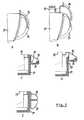
- FIG. 2schematically shows two different configurations of a bottom
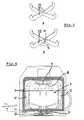
- FIG. 3perspectively shows two different configurations of air guide ribs
- FIG. 4shows another embodiment of the apparatus according to the invention in a schematical vertical cross-sectional view
- FIG. 5shows three different grip configurations
- FIG. 6perspectively shows an embodiment of a heat reflector
- FIG. 7shows, in a schematical vertical cross-sectional view, an embodiment of the apparatus according to the invention destined to be built-in in a surface
- FIG. 8shows an alternative configuration of air guide ribs.
- the apparatuscomprises an outer shell 1 which may be fabricated of a plastic material.
- a double-walled food preparation chamber 2is defined surrounded by an inner wall 3 and an outer wall 4 .
- the inner wall 3is provided with an air-permeable bottom section 5 .
- the inner wallis provided with a discharge opening 6 for air.
- a fan 7is positioned which is driven by an electric motor 8 (of which the speed may be controllable).
- an electric motor 8of which the speed may be controllable.
- airis sucked from the food preparation chamber 2 through the discharge opening 6 , and is delivered at a high pressure in a channel 9 defined between the inner wall 3 and outer wall 4 .
- the airis forced through said channel 9 towards and through the air-permeable bottom section 5 of the inner wall 3 to arrive again at the food preparation chamber 2 .
- FIG. 1suggests that the channel 9 between the inner wall 3 and outer wall 4 continuously surrounds the food preparation chamber 2 to define an annular channel, it also conceivable that there are a number of distinct channels leading from the fan 7 towards the bottom section 5 .
- heat radiating elements 10In the upper part of the food preparation chamber one (or a number of) heat radiating elements 10 is positioned which not only radiates heat into the food preparation chamber and towards any food present therein, but also heats the air circulating in the apparatus and flowing upwardly past said heat radiating means 10 .
- the heat radiating element(s) 10can take a number of forms, but commonly, is/are elongated, electric (resistive) heat radiating element(s), the voltage and/or current supplied thereto from a power source 32 being controlled by a controller herein represented by control panel 14 .
- the manner in which the heat radiating element 10 obtains heat for radiatingis not important in that the source of power (heat) can be obtained from electricity, natural gas or oil to name a few and the heat radiating element can be solid or hollow (for example filled with a heat transmitting fluid such as steam).
- air guide member 11Below the bottom section 5 sitting on the outer wall 4 is air guide member 11 .
- the arrangement and/or shape of this air guide member 11is such that the arriving air is directed upwardly through the bottom section 5 and into the food preparation chamber 2 with a regular flow pattern.
- the air guide member sitting on the outer wall 4provides an unobstructed air flow pattern (that means without the presence of food) having the highest velocity in the central location of the food preparation chamber 2 and decreasing radially outward. Then, when food is present the resulting air flow can have the required regular pattern.
- the bottom section 5 of the inner wall 3 of the food preparation chamberhas, at least partly, an open structure, for example by being defined by a grid or mesh structure.
- FIG. 2shows two alternative embodiments in which the food preparation chamber 2 has a circumferential wall 3 ′ with a lower end 3 ′′ extending downwardly beyond the connection between said circumferential wall 3 ′ and the bottom section 5 of the food preparation chamber.
- said lower end 3 ′′is straight and in FIG. 2B it is curved inwardly.
- Such lower end 3 ′′prevents a disturbance of the upward airflow by the downward airflow out of channel 9 (see FIG. 1 ).
- the food preparation chamber 2comprises an upper portion 2 ′ and a removable lower portion 2 ′′.
- the lower part 2 ′′ of the food preparation chambercomprises a grip 12 .
- the bottom sectionmay be part of a basket-like member 13 (indicated in FIG. 2 ) within the double wall. Basically such a basket-like member will comprise (vertically or inclined) upwardly extending walls (e.g 13 ′ in FIG. 2 ) and a horizontally extending bottom wall which in the present embodiment is defined by the bottom section 5 .
- the lower portion 2 ′′ of the food preparation chambercan be removed from the shell 1 .
- a userthen can inspect the food in the basket-like member 13 and can, if needed, shake the basket-like member for disturbing the food therein or may choose different settings for the operation of the apparatus by means of a control panel (to be discussed below).
- valve membersfor example valve members
- meansfor example valve members
- filtration openingswhich may be provided to cope with an increasing pressure within the food preparation chamber due to the heating of the food.
- the upwardly extending walls 13 ′ of the basket-like member 13diverge in such a way that the basket-like member 13 has an inverted frusto-conical shape.
- a disposition of the food therein having a cross-sectional area increasing upwardlyis provided which can be helpful in obtaining the regular flow pattern and even processing or preparing of the food sought for.
- control panel 14is shown with which the operation of the apparatus can be controlled (e.g. by setting parameters such as temperature, heating time, flow velocity etcetera).
- FIG. 3shows two embodiments of an air guide member 11 comprising air guide ribs 15 .
- air guide ribs 15are four in number and are arranged in vertical planes, extend radially and meet at a central location.
- the guide ribssubstantially are arranged in the shape of a Greek cross. Such ribs 15 promote the upward air flow, prevent a circular (swirling) air flow and create a pressure increase towards the central location.
- FIG. 3Bunderneath or combined with said air guide ribs and concentrically therewith a frusto-conical upwardly tapering air guide part 11 is arranged.
- the upwardly tapering circumferential surface 16 of this air guide part 11helps in directing air arriving from the channel 9 (see FIG. 1 ) upwardly into the food preparation chamber 2 .
- FIG. 8shows a top plan view of an alternative embodiment of the air guide ribs 15 ′ with a curved extension, of which preferably the direction of curve is determined by the rotation direction of the fan such that the air converges in the center.
- the air guide ribs 15 or 15 ′ and, if provided, the air guide part 11may define an assembly which is removable from the remainder of the apparatus.
- FIG. 4illustrates, in a view similar to FIG. 1 , an alternative embodiment of the apparatus. Only the differences with respect to the embodiment according to FIG. 1 will be discussed.
- air guides 17are provided in channel 9 for returning the air from the discharge opening 6 towards the bottom wall 5 . These air guides 17 are useful in preventing a circumferential, swirling air flow in said channel 9 .
- a heat reflector 18is provided in the upper part of the food preparation chamber 2 .
- This heat reflector 18comprises a central opening 19 defining the discharge opening 6 . Further this heat reflector 18 defines radially extending air guides 20 which then are positioned at the start of the channel 9 for returning the air from the discharge opening 6 towards the bottom wall 5 . These air guides 20 also prevent a circumferential flow of the air in the channel 9 , in addition to the air guides 17 . Said heat reflector 18 may be removable.
- mechanism 21which is provided for preloading the lower portion 2 ′′ towards the upper portion 2 ′ of the food preparation chamber.
- Such meansmay comprise a spring 22 located underneath the lower part of the food preparation chamber 2 .
- such a mechanismmay comprise a switch 34 cooperating with the removable portion 2 ′′ of the food preparation chamber.
- the switch 34is operated providing an input to the controller to reactive power to the heat radiating element 10 and/or fan 14 .
- other positions of such a switch 34are conceivable too.
- FIG. 5shows alternative grip embodiments.
- FIGS. 5A and 5Bshow a lower portion 2 ′′ with first grip part 23 and a basket 13 with second grip part 24 .
- the grip parts 23 and 24are nested to define a unitary combined grip.
- FIGS. 5C and 5Dshow a basket 13 with grip 25 which is provided with a manually operable locking mechanism 26 , and a lower portion 2 ′′ with locking part 27 cooperating with the locking mechanism 26 of the grip 25 when the basket 13 is positioned within the lower portion 2 ′′.
- FIG. 5Eillustrates a basket 13 with grip part 28 and lower portion 2 ′′ with grip part 29 .
- the grip parts 28 and 29are positioned in a common vertical plane one above the other.
- the basketfirst should be rotated in such a manner that both grip parts 28 and 29 are no longer positioned in a common plane.
- grip embodimentssuch as for example grip parts of the basket and lower portion which in the assembled position are located closely alongside each other.
- FIG. 7illustrates an embodiment of the apparatus which can be built-in in a surface 30 , for example a table top.
Landscapes
- Engineering & Computer Science (AREA)
- Food Science & Technology (AREA)
- Chemical & Material Sciences (AREA)
- Combustion & Propulsion (AREA)
- Mechanical Engineering (AREA)
- General Engineering & Computer Science (AREA)
- Baking, Grill, Roasting (AREA)
- General Preparation And Processing Of Foods (AREA)
- Cookers (AREA)
- Formation And Processing Of Food Products (AREA)
- Food Preservation Except Freezing, Refrigeration, And Drying (AREA)
- Confectionery (AREA)
Abstract
Description
Claims (34)
Applications Claiming Priority (4)
| Application Number | Priority Date | Filing Date | Title |
|---|---|---|---|
| EP06115609.7 | 2006-06-16 | ||
| EP06115609 | 2006-06-16 | ||
| EP06115609AEP1867264A1 (en) | 2006-06-16 | 2006-06-16 | Apparatus for preparing food |
| PCT/EP2007/055993WO2007144432A1 (en) | 2006-06-16 | 2007-06-18 | Apparatus for preparing food and air guide member therefor |
Related Parent Applications (1)
| Application Number | Title | Priority Date | Filing Date |
|---|---|---|---|
| PCT/EP2007/055993Continuation-In-PartWO2007144432A1 (en) | 2006-06-16 | 2007-06-18 | Apparatus for preparing food and air guide member therefor |
Publications (2)
| Publication Number | Publication Date |
|---|---|
| US20090134140A1 US20090134140A1 (en) | 2009-05-28 |
| US8299404B2true US8299404B2 (en) | 2012-10-30 |
Family
ID=37395765
Family Applications (1)
| Application Number | Title | Priority Date | Filing Date |
|---|---|---|---|
| US12/335,012Active2029-05-13US8299404B2 (en) | 2006-06-16 | 2008-12-15 | Apparatus for preparing food and air guide member therefor |
Country Status (16)
| Country | Link |
|---|---|
| US (1) | US8299404B2 (en) |
| EP (2) | EP1867264A1 (en) |
| JP (4) | JP5340142B2 (en) |
| KR (2) | KR101398481B1 (en) |
| CN (1) | CN101500462B (en) |
| AT (1) | ATE464823T1 (en) |
| AU (1) | AU2007259266B2 (en) |
| BR (1) | BRPI0713087B1 (en) |
| CA (1) | CA2655284C (en) |
| DE (1) | DE602007006016D1 (en) |
| DK (1) | DK2034872T3 (en) |
| ES (1) | ES2343480T3 (en) |
| MX (1) | MX2008016234A (en) |
| PL (1) | PL2034872T3 (en) |
| RU (1) | RU2444971C2 (en) |
| WO (1) | WO2007144432A1 (en) |
Cited By (21)
| Publication number | Priority date | Publication date | Assignee | Title |
|---|---|---|---|---|
| US20120125313A1 (en)* | 2008-09-23 | 2012-05-24 | Kavaring Cooking Systems B.V. | Apparatus for preparing food and air guide member therefor |
| US20160113442A1 (en)* | 2013-06-04 | 2016-04-28 | Koninklijke Philips N.V. | Air fryer |
| US20160356506A1 (en)* | 2015-06-08 | 2016-12-08 | Appliance Innovation, Inc. | Convection oven |
| US20170245683A1 (en)* | 2014-10-23 | 2017-08-31 | Koninklijke Philips N.V. | Apparatus and method for preparing food |
| US9854941B2 (en) | 2014-05-23 | 2018-01-02 | Koninklijke Philips N.V. | Lid for reducing fumes in an air-based fryer |
| US10307018B2 (en)* | 2010-09-10 | 2019-06-04 | Koninklijke Philips N.V. | Apparatus for preparing food |
| US20190231143A1 (en)* | 2017-08-09 | 2019-08-01 | Sharkninja Operating Llc | Cooking device and components thereof |
| USD873602S1 (en) | 2018-08-09 | 2020-01-28 | Sharkninja Operating Llc | Lid part of a food preparation device |
| USD874211S1 (en) | 2018-08-09 | 2020-02-04 | Sharkninja Operating Llc | Food preparation device and parts thereof |
| USD903415S1 (en) | 2018-08-09 | 2020-12-01 | Sharkninja Operating Llc | Cooking basket |
| USD914447S1 (en) | 2018-06-19 | 2021-03-30 | Sharkninja Operating Llc | Air diffuser |
| US10966568B2 (en) | 2014-09-17 | 2021-04-06 | Koninklijke Philips N.V. | Air-based fryer apparatus for preparing food |
| USD918654S1 (en) | 2019-06-06 | 2021-05-11 | Sharkninja Operating Llc | Grill plate |
| USD922126S1 (en) | 2019-06-06 | 2021-06-15 | Sharkninja Operating Llc | User interface for a food preparation device |
| US11033146B2 (en) | 2019-02-25 | 2021-06-15 | Sharkninja Operating Llc | Cooking device and components thereof |
| US20210219777A1 (en)* | 2018-06-11 | 2021-07-22 | Koninklijke Philips N.V. | Air-based fryer and accessory for an air-based fryer |
| US11134808B2 (en) | 2020-03-30 | 2021-10-05 | Sharkninja Operating Llc | Cooking device and components thereof |
| USD932833S1 (en) | 2018-08-09 | 2021-10-12 | Sharkninja Operating Llc | Reversible cooking rack |
| US11751710B2 (en) | 2019-02-25 | 2023-09-12 | Sharkninja Operating Llc | Guard for cooking system |
| US11882961B1 (en) | 2023-01-18 | 2024-01-30 | Sharkninja Operating Llc | Cover plate for cooking devices |
| USD1075406S1 (en) | 2023-08-29 | 2025-05-20 | Sharkninja Operating Llc | Stacked air fryer |
Families Citing this family (31)
| Publication number | Priority date | Publication date | Assignee | Title |
|---|---|---|---|---|
| EP2532971A1 (en) | 2011-06-07 | 2012-12-12 | Koninklijke Philips Electronics N.V. | Apparatus for preparing food |
| CA2867157C (en)* | 2012-03-29 | 2017-01-24 | B/E Aerospace, Inc. | Vehicle oven having optimized airflow |
| CN102670088A (en)* | 2012-06-11 | 2012-09-19 | 周林斌 | Air frying basket |
| CN103006092A (en)* | 2012-11-23 | 2013-04-03 | 杨振巧 | Air frying pan |
| CN105263379A (en)* | 2013-06-04 | 2016-01-20 | 皇家飞利浦有限公司 | Air-based fryer |
| RU2660074C2 (en)* | 2013-06-04 | 2018-07-04 | Конинклейке Филипс Н.В. | Air-based fryer pan |
| CN105307547B (en)* | 2013-06-04 | 2019-02-15 | 皇家飞利浦有限公司 | Air fryer |
| CN103690065A (en)* | 2013-07-19 | 2014-04-02 | 慈溪市宏邦电器有限公司 | Air fryer for fully and evenly heating food |
| CN104414427A (en) | 2013-08-26 | 2015-03-18 | 皇家飞利浦有限公司 | Apparatus having drawers with sliding mechanism for preparing food |
| ES2572647T3 (en) | 2013-09-11 | 2016-06-01 | Compañía Española De Electromenaje, Sa | Apparatus for cooking food by hot air |
| RU2678373C1 (en)* | 2013-12-13 | 2019-01-28 | Конинклейке Филипс Н.В. | Air guide member in air-based fryer |
| CN106470709A (en)* | 2014-06-30 | 2017-03-01 | 皇家飞利浦有限公司 | Sterilizing cabinet for clothes |
| RU2693865C2 (en)* | 2014-10-15 | 2019-07-05 | Конинклейке Филипс Н.В. | Insert for air based frying device, device containing such insert |
| KR102247218B1 (en)* | 2014-11-21 | 2021-05-04 | 엘지전자 주식회사 | Discharging apparatus and cooking device |
| CN104473570B (en)* | 2014-12-18 | 2016-05-11 | 严绍基 | Air is complained and quarrel loudly |
| CN107510379B (en)* | 2016-06-15 | 2022-07-15 | 皇家飞利浦有限公司 | Air fryer |
| CN109414137B (en) | 2016-06-15 | 2022-08-26 | 皇家飞利浦有限公司 | Air fryer |
| CN107616715B (en)* | 2016-07-13 | 2024-04-09 | 深圳市联创三金电器有限公司 | Food preparation device utilizing hot air circulation |
| CN107928440A (en)* | 2016-10-13 | 2018-04-20 | 深圳市联创三金电器有限公司 | The equipment that food is made using hot-air |
| EP3395217A1 (en)* | 2017-04-28 | 2018-10-31 | Koninklijke Philips N.V. | Food support for an air based fryer and air-based fryer provided with such food support |
| CN109381074B (en)* | 2017-08-14 | 2022-09-02 | 广东美的生活电器制造有限公司 | Wind scooper, base assembly and food processor |
| EP3583878A1 (en) | 2018-06-18 | 2019-12-25 | Koninklijke Philips N.V. | Air-based fryer |
| JP6615966B1 (en)* | 2018-06-29 | 2019-12-04 | 株式会社日本輸出自動車検査センター | Automotive high temperature pest control equipment |
| CN110870678B (en)* | 2018-08-29 | 2022-05-24 | 佛山市顺德区美的电热电器制造有限公司 | Cooking utensil and pot lid subassembly thereof |
| CN111374567B (en)* | 2018-12-29 | 2022-09-06 | 佛山市顺德区美的电热电器制造有限公司 | Baking appliance |
| CN109875418A (en)* | 2019-03-28 | 2019-06-14 | 九阳股份有限公司 | Cooking apparatus with fryer function |
| EP3838086A1 (en)* | 2019-12-19 | 2021-06-23 | Koninklijke Philips N.V. | Configurable air fryer and method of operating the same |
| CN113251449B (en)* | 2021-05-17 | 2023-01-31 | 广东美的厨房电器制造有限公司 | cooking equipment |
| CN118266743A (en)* | 2021-12-03 | 2024-07-02 | 广东顺德欧宁科技电器有限公司 | Electric pressure cooker with pressure cooking and air frying cooking functions and heating method thereof |
| CN218791882U (en) | 2022-03-03 | 2023-04-07 | 九阳股份有限公司 | Air fryer |
| IT202200020730A1 (en)* | 2022-10-07 | 2024-04-07 | De Longhi Appliances Srl | APPARATUS AND RELATED KIT FOR COOKING FOOD |
Citations (27)
| Publication number | Priority date | Publication date | Assignee | Title |
|---|---|---|---|---|
| US2966573A (en)* | 1960-12-27 | hansen | ||
| US3586516A (en)* | 1969-04-18 | 1971-06-22 | Fred C Smith | Meat defrosting apparatus |
| GB1319855A (en) | 1969-06-25 | 1973-06-13 | Hueber M | Foodstuff handling assemblies |
| US3783832A (en)* | 1972-05-19 | 1974-01-08 | A Marsh | Automatic egg incubator |
| US3820525A (en)* | 1973-08-10 | 1974-06-28 | J Pond | Radiation and convection heated oven |
| US3821454A (en)* | 1971-12-15 | 1974-06-28 | Leon Lobel | Method of ageing meat |
| US3825723A (en)* | 1973-02-14 | 1974-07-23 | Otto Engineering | Temperature and humidity test apparatus |
| US3828760A (en)* | 1973-05-23 | 1974-08-13 | Lca Corp | Oven |
| US4010341A (en)* | 1972-11-13 | 1977-03-01 | Ifo Kampri Ab | Hot air oven |
| FR2406984A1 (en) | 1977-10-26 | 1979-05-25 | Villamos Berendezes Es Keszule | AIR BREAKING DEVICE FOR COTTAGE |
| US4374319A (en) | 1979-11-27 | 1983-02-15 | Sunset Ltd. | Counter-top oven |
| US4374318A (en)* | 1980-09-08 | 1983-02-15 | Umc Industries, Inc. | Apparatus for heating food, such as french fried potatoes |
| US4426923A (en) | 1982-06-18 | 1984-01-24 | Takashi Ohata | Storage device for processed foods |
| US4484064A (en)* | 1982-07-26 | 1984-11-20 | Murray Jerome L | Coffee roaster |
| US4494683A (en)* | 1981-10-05 | 1985-01-22 | Kurt Kleber | Steam kiln |
| US4591698A (en)* | 1984-03-12 | 1986-05-27 | Chang Hong Tsuan | Electric dual and quick cooking utensil |
| EP0279065A2 (en) | 1987-02-06 | 1988-08-24 | Electrolux-Juno Küchentechnik GmbH | Device for controlling the steam in a steam-proofing apparatus |
| US4771162A (en)* | 1985-12-18 | 1988-09-13 | Fkb Feinwerktechnik Und Kunststoffverarbeitungs Gmbh | Apparatus for treating plastic parts for use in dental and orthodontic applications |
| EP0284420A1 (en) | 1987-03-26 | 1988-09-28 | Howard Roth | Microwave heating apparatus and method |
| EP0489954A1 (en) | 1990-12-12 | 1992-06-17 | Societe Des Produits Nestle S.A. | Process and apparatus for cooking food products with warm humid air |
| US5466912A (en)* | 1993-04-13 | 1995-11-14 | American Harvest, Inc. | Convection oven |
| US5485780A (en)* | 1993-02-26 | 1996-01-23 | Food Automation Service Techniques, Inc. | Rotisserie oven |
| US5513558A (en)* | 1987-02-17 | 1996-05-07 | American Harvest, Inc. | Rapid cooking device |
| US5676870A (en) | 1994-05-25 | 1997-10-14 | Ultravection International, Inc. | Convectively-enhanced radiant heat oven |
| US6198076B1 (en)* | 1999-11-17 | 2001-03-06 | National Presto Industries, Inc. | Convection oven |
| USRE37238E1 (en)* | 1994-11-03 | 2001-06-26 | Hearthware Home Products, Inc. | Apparatus for roasting coffee beans |
| WO2005048796A1 (en) | 2003-11-21 | 2005-06-02 | Soparfin Sa | Device for heating foodstuff with hot air |
Family Cites Families (11)
| Publication number | Priority date | Publication date | Assignee | Title |
|---|---|---|---|---|
| US279065A (en)* | 1883-06-05 | Electrical apparatus for automatic signaling | ||
| US489954A (en)* | 1893-01-17 | Device for facilitating copying | ||
| JPS51186A (en)* | 1974-06-08 | 1976-01-05 | Bioo Medeikasu Inc | SHUJUTSUYOBURITSUJI |
| JPS51186U (en)* | 1974-06-19 | 1976-01-05 | ||
| JPS57155039A (en)* | 1981-03-20 | 1982-09-25 | Matsushita Electric Ind Co Ltd | Cooking heater |
| JPS5886329A (en)* | 1981-11-18 | 1983-05-23 | Matsushita Electric Ind Co Ltd | Heat cooker |
| JPH04295523A (en)* | 1991-03-22 | 1992-10-20 | Matsushita Electric Ind Co Ltd | Thermal cooker |
| DE4124742C2 (en)* | 1991-07-25 | 1994-06-09 | Eloma Gmbh | Cooking appliance, especially for lumpy food |
| US5481962A (en)* | 1994-04-22 | 1996-01-09 | Tedesco; Jon D. | Countertop puffing oven for pelletized foodstuffs |
| US5878655A (en)* | 1996-11-18 | 1999-03-09 | China Packific Trade Ltd. | Automatic baking apparatus |
| US6444955B1 (en)* | 2000-09-27 | 2002-09-03 | Ultravection International, Inc. | Cooking enhancing convection oven and method of enhancing the cooking in a convection oven |
- 2006
- 2006-06-16EPEP06115609Apatent/EP1867264A1/ennot_activeWithdrawn
- 2007
- 2007-06-18DKDK07765460.6Tpatent/DK2034872T3/enactive
- 2007-06-18CNCN2007800294893Apatent/CN101500462B/enactiveActive
- 2007-06-18BRBRPI0713087-2Apatent/BRPI0713087B1/enactiveIP Right Grant
- 2007-06-18EPEP07765460Apatent/EP2034872B9/enactiveActive
- 2007-06-18RURU2009100843/12Apatent/RU2444971C2/ennot_activeIP Right Cessation
- 2007-06-18KRKR1020097000207Apatent/KR101398481B1/enactiveActive
- 2007-06-18CACA2655284Apatent/CA2655284C/enactiveActive
- 2007-06-18JPJP2009514817Apatent/JP5340142B2/enactiveActive
- 2007-06-18PLPL07765460Tpatent/PL2034872T3/enunknown
- 2007-06-18AUAU2007259266Apatent/AU2007259266B2/enactiveActive
- 2007-06-18MXMX2008016234Apatent/MX2008016234A/enactiveIP Right Grant
- 2007-06-18KRKR20147007346Apatent/KR101482581B1/enactiveActive
- 2007-06-18ESES07765460Tpatent/ES2343480T3/enactiveActive
- 2007-06-18WOPCT/EP2007/055993patent/WO2007144432A1/enactiveApplication Filing
- 2007-06-18DEDE602007006016Tpatent/DE602007006016D1/enactiveActive
- 2007-06-18ATAT07765460Tpatent/ATE464823T1/ennot_activeIP Right Cessation
- 2008
- 2008-12-15USUS12/335,012patent/US8299404B2/enactiveActive
- 2013
- 2013-06-10JPJP2013121539Apatent/JP5756494B2/enactiveActive
- 2014
- 2014-07-07JPJP2014139458Apatent/JP6053726B2/enactiveActive
- 2016
- 2016-08-25JPJP2016164440Apatent/JP6211659B2/enactiveActive
Patent Citations (28)
| Publication number | Priority date | Publication date | Assignee | Title |
|---|---|---|---|---|
| US2966573A (en)* | 1960-12-27 | hansen | ||
| US3586516A (en)* | 1969-04-18 | 1971-06-22 | Fred C Smith | Meat defrosting apparatus |
| GB1319855A (en) | 1969-06-25 | 1973-06-13 | Hueber M | Foodstuff handling assemblies |
| US3821454A (en)* | 1971-12-15 | 1974-06-28 | Leon Lobel | Method of ageing meat |
| US3783832A (en)* | 1972-05-19 | 1974-01-08 | A Marsh | Automatic egg incubator |
| US4010341A (en)* | 1972-11-13 | 1977-03-01 | Ifo Kampri Ab | Hot air oven |
| US3825723A (en)* | 1973-02-14 | 1974-07-23 | Otto Engineering | Temperature and humidity test apparatus |
| US3828760A (en)* | 1973-05-23 | 1974-08-13 | Lca Corp | Oven |
| US3820525A (en)* | 1973-08-10 | 1974-06-28 | J Pond | Radiation and convection heated oven |
| FR2406984A1 (en) | 1977-10-26 | 1979-05-25 | Villamos Berendezes Es Keszule | AIR BREAKING DEVICE FOR COTTAGE |
| US4374319A (en) | 1979-11-27 | 1983-02-15 | Sunset Ltd. | Counter-top oven |
| US4374318A (en)* | 1980-09-08 | 1983-02-15 | Umc Industries, Inc. | Apparatus for heating food, such as french fried potatoes |
| US4494683A (en)* | 1981-10-05 | 1985-01-22 | Kurt Kleber | Steam kiln |
| US4426923A (en) | 1982-06-18 | 1984-01-24 | Takashi Ohata | Storage device for processed foods |
| US4484064A (en)* | 1982-07-26 | 1984-11-20 | Murray Jerome L | Coffee roaster |
| US4591698A (en)* | 1984-03-12 | 1986-05-27 | Chang Hong Tsuan | Electric dual and quick cooking utensil |
| US4771162A (en)* | 1985-12-18 | 1988-09-13 | Fkb Feinwerktechnik Und Kunststoffverarbeitungs Gmbh | Apparatus for treating plastic parts for use in dental and orthodontic applications |
| EP0279065A2 (en) | 1987-02-06 | 1988-08-24 | Electrolux-Juno Küchentechnik GmbH | Device for controlling the steam in a steam-proofing apparatus |
| US5513558A (en)* | 1987-02-17 | 1996-05-07 | American Harvest, Inc. | Rapid cooking device |
| EP0284420A1 (en) | 1987-03-26 | 1988-09-28 | Howard Roth | Microwave heating apparatus and method |
| EP0489954A1 (en) | 1990-12-12 | 1992-06-17 | Societe Des Produits Nestle S.A. | Process and apparatus for cooking food products with warm humid air |
| US5485780A (en)* | 1993-02-26 | 1996-01-23 | Food Automation Service Techniques, Inc. | Rotisserie oven |
| US5466912A (en)* | 1993-04-13 | 1995-11-14 | American Harvest, Inc. | Convection oven |
| US5676870A (en) | 1994-05-25 | 1997-10-14 | Ultravection International, Inc. | Convectively-enhanced radiant heat oven |
| USRE37238E1 (en)* | 1994-11-03 | 2001-06-26 | Hearthware Home Products, Inc. | Apparatus for roasting coffee beans |
| US6198076B1 (en)* | 1999-11-17 | 2001-03-06 | National Presto Industries, Inc. | Convection oven |
| WO2005048796A1 (en) | 2003-11-21 | 2005-06-02 | Soparfin Sa | Device for heating foodstuff with hot air |
| US20070125354A1 (en) | 2003-11-21 | 2007-06-07 | Patrick Boesch | Device for heating foodstuff with hot air |
Non-Patent Citations (2)
| Title |
|---|
| Official Search Report of the European Patent Office in counterpart foreign application No. PCT/EP2007/055993 filed Jun. 18, 2007. |
| Written Opinion of the European Patent Office in counterpart foreign application No. PCT/EP2007/055993 filed Jun. 18, 2007. |
Cited By (93)
| Publication number | Priority date | Publication date | Assignee | Title |
|---|---|---|---|---|
| US10448785B2 (en)* | 2008-09-23 | 2019-10-22 | Koninklijke Philips N.V. | Apparatus for preparing food and air guide member therefor |
| US20120125313A1 (en)* | 2008-09-23 | 2012-05-24 | Kavaring Cooking Systems B.V. | Apparatus for preparing food and air guide member therefor |
| US11337552B2 (en) | 2008-09-23 | 2022-05-24 | Koninklijke Philips N.V. | Apparatus for preparing food and air guide member therefor |
| US10307018B2 (en)* | 2010-09-10 | 2019-06-04 | Koninklijke Philips N.V. | Apparatus for preparing food |
| US20160113442A1 (en)* | 2013-06-04 | 2016-04-28 | Koninklijke Philips N.V. | Air fryer |
| US9980605B2 (en)* | 2013-06-04 | 2018-05-29 | Koninklijke Philips N.V. | Air fryer |
| US9854941B2 (en) | 2014-05-23 | 2018-01-02 | Koninklijke Philips N.V. | Lid for reducing fumes in an air-based fryer |
| US10966568B2 (en) | 2014-09-17 | 2021-04-06 | Koninklijke Philips N.V. | Air-based fryer apparatus for preparing food |
| US20170245683A1 (en)* | 2014-10-23 | 2017-08-31 | Koninklijke Philips N.V. | Apparatus and method for preparing food |
| US11116359B2 (en)* | 2014-10-23 | 2021-09-14 | Koninklijke Philips N.V. | Apparatus and method for preparing food |
| US20160356506A1 (en)* | 2015-06-08 | 2016-12-08 | Appliance Innovation, Inc. | Convection oven |
| US10337745B2 (en)* | 2015-06-08 | 2019-07-02 | Alto-Shaam, Inc. | Convection oven |
| US11445856B2 (en) | 2017-08-09 | 2022-09-20 | Sharkninja Operating Llc | Cooking device and components thereof |
| US10674868B2 (en) | 2017-08-09 | 2020-06-09 | Sharkninja Operating Llc | Cooking device and components thereof |
| US10405698B2 (en) | 2017-08-09 | 2019-09-10 | Sharkninja Operating Llc | Cooking device and components thereof |
| US10405697B2 (en)* | 2017-08-09 | 2019-09-10 | Sharkninja Operating Llc | Cooking device and components thereof |
| US10413122B2 (en) | 2017-08-09 | 2019-09-17 | Sharkninja Operating Llc | Cooking device and components thereof |
| US10413121B2 (en) | 2017-08-09 | 2019-09-17 | Sharkninja Operating Llc | Cooking device and components thereof |
| US20190231127A1 (en)* | 2017-08-09 | 2019-08-01 | Sharkninja Operating Llc | Cooking device and components thereof |
| US10485378B2 (en) | 2017-08-09 | 2019-11-26 | Sharkninja Operating Llc | Cooking device and components thereof |
| US20190231126A1 (en)* | 2017-08-09 | 2019-08-01 | Sharkninja Operating Llc | Cooking device and components thereof |
| US11889950B2 (en) | 2017-08-09 | 2024-02-06 | Sharkninja Operating Llc | Cooking device and components thereof |
| US20200060473A1 (en)* | 2017-08-09 | 2020-02-27 | Sharkninja Operating Llc | Cooking device and components thereof |
| US11759049B2 (en) | 2017-08-09 | 2023-09-19 | Sharkninja Operating Llc | Cooking device and components thereof |
| US11759048B2 (en)* | 2017-08-09 | 2023-09-19 | Sharkninja Operating Llc | Cooking device and components thereof |
| US11627834B2 (en) | 2017-08-09 | 2023-04-18 | Sharkninja Operating Llc | Cooking system for cooking food |
| US11547242B2 (en) | 2017-08-09 | 2023-01-10 | Sharkninja Operating Llc | Cooking device and components thereof |
| US11547243B2 (en) | 2017-08-09 | 2023-01-10 | Sharkninja Operating Llc | Cooking device and components thereof |
| US10646070B2 (en) | 2017-08-09 | 2020-05-12 | Sharkninja Operating Llc | Cooking device and components thereof |
| US10653270B2 (en)* | 2017-08-09 | 2020-05-19 | Sharkninja Operating Llc | Cooking device and components thereof |
| US10660472B2 (en)* | 2017-08-09 | 2020-05-26 | Sharkninja Operating Llc | Cooking device and components thereof |
| US11109710B2 (en) | 2017-08-09 | 2021-09-07 | Sharkninja Operating Llc | Cooking device and components thereof |
| US10682011B2 (en) | 2017-08-09 | 2020-06-16 | Sharkninja Operating Llc | Cooking device and components thereof |
| US10390656B2 (en) | 2017-08-09 | 2019-08-27 | Sharkninja Operating Llc | Cooking device and components thereof |
| US20190231143A1 (en)* | 2017-08-09 | 2019-08-01 | Sharkninja Operating Llc | Cooking device and components thereof |
| US11399657B2 (en)* | 2017-08-09 | 2022-08-02 | Sharkninja Operating Llc | Cooking device and components thereof |
| US11266267B2 (en) | 2017-08-09 | 2022-03-08 | Sharkninja Operating Llc | Cooking device and components thereof |
| US11266268B2 (en)* | 2017-08-09 | 2022-03-08 | Sharkninja Operating Llc | Cooking device and components thereof |
| US20190231135A1 (en)* | 2017-08-09 | 2019-08-01 | Sharkninja Operating Llc | Cooking device and components thereof |
| US11363910B2 (en)* | 2017-08-09 | 2022-06-21 | Sharkninja Operating Llc | Cooking device and components thereof |
| US20190231128A1 (en)* | 2017-08-09 | 2019-08-01 | Sharkninja Operating Llc | Cooking device and components thereof |
| US11089902B2 (en) | 2017-08-09 | 2021-08-17 | Sharkninja Operating Llc | Cooking device and components thereof |
| US11304561B2 (en)* | 2017-08-09 | 2022-04-19 | Sharkninja Operating Llc | Cooking device and components thereof |
| US11278151B2 (en) | 2017-08-09 | 2022-03-22 | Sharkninja Operating Llc | Cooking device and components thereof |
| US11089903B2 (en) | 2017-08-09 | 2021-08-17 | Sharkninja Operating Llc | Cooking device and components thereof |
| US20210219777A1 (en)* | 2018-06-11 | 2021-07-22 | Koninklijke Philips N.V. | Air-based fryer and accessory for an air-based fryer |
| US12364361B2 (en)* | 2018-06-11 | 2025-07-22 | Koninklijke Philips N.V. | Air-based fryer and accessory for an air-based fryer |
| USD948938S1 (en) | 2018-06-19 | 2022-04-19 | Sharkninja Operating Llc | Air diffuser |
| USD914436S1 (en) | 2018-06-19 | 2021-03-30 | Sharkninja Operating Llc | Air diffuser with food preparation pot |
| USD914447S1 (en) | 2018-06-19 | 2021-03-30 | Sharkninja Operating Llc | Air diffuser |
| USD903415S1 (en) | 2018-08-09 | 2020-12-01 | Sharkninja Operating Llc | Cooking basket |
| USD883016S1 (en) | 2018-08-09 | 2020-05-05 | Sharkninja Operating Llc | Food preparation device and parts thereof |
| USD931680S1 (en) | 2018-08-09 | 2021-09-28 | Sharkninja Operating Llc | Cooking basket |
| USD873602S1 (en) | 2018-08-09 | 2020-01-28 | Sharkninja Operating Llc | Lid part of a food preparation device |
| USD932833S1 (en) | 2018-08-09 | 2021-10-12 | Sharkninja Operating Llc | Reversible cooking rack |
| USD874211S1 (en) | 2018-08-09 | 2020-02-04 | Sharkninja Operating Llc | Food preparation device and parts thereof |
| USD934027S1 (en) | 2018-08-09 | 2021-10-26 | Sharkninja Operating Llc | Reversible cooking rack |
| USD876874S1 (en) | 2018-08-09 | 2020-03-03 | Sharkninja Operating Llc | User interface for a food preparation device |
| USD935259S1 (en) | 2018-08-09 | 2021-11-09 | Sharkninja Operating Llc | Food preparation device |
| USD940503S1 (en) | 2018-08-09 | 2022-01-11 | Sharkninja Operating Llc | Cooking basket |
| USD941090S1 (en) | 2018-08-09 | 2022-01-18 | Sharkninja Operating Llc | Cooking basket |
| USD929794S1 (en) | 2018-08-09 | 2021-09-07 | Sharkninja Operating Llc | Food preparation device |
| USD929173S1 (en) | 2018-08-09 | 2021-08-31 | Sharkninja Operating Llc | Food preparation device |
| USD883017S1 (en) | 2018-08-09 | 2020-05-05 | Sharkninja Operating Llc | User interface for food preparation device |
| USD883014S1 (en) | 2018-08-09 | 2020-05-05 | Sharkninja Operating Llc | Food preparation device |
| USD883015S1 (en) | 2018-08-09 | 2020-05-05 | Sharkninja Operating Llc | Food preparation device and parts thereof |
| USD920732S1 (en) | 2018-08-09 | 2021-06-01 | Sharkninja Operating Llc | Food preparation device |
| USD929793S1 (en) | 2018-08-09 | 2021-09-07 | Sharkninja Operating Llc | Food preparation device |
| USD903413S1 (en) | 2018-08-09 | 2020-12-01 | Sharkninja Operating Llc | Cooking basket |
| USD903414S1 (en) | 2018-08-09 | 2020-12-01 | Sharkninja Operating Llc | Cooking basket |
| US11051654B2 (en) | 2019-02-25 | 2021-07-06 | Sharkninja Operating Llc | Cooking device and components thereof |
| US12226039B2 (en) | 2019-02-25 | 2025-02-18 | Sharkninja Operating Llc | Guard for cooking system |
| US11363911B2 (en) | 2019-02-25 | 2022-06-21 | Sharkninja Operating Llc | Cooking device and components thereof |
| US11147415B2 (en) | 2019-02-25 | 2021-10-19 | Sharkninja Operating Llc | Cooking device and components thereof |
| US11033146B2 (en) | 2019-02-25 | 2021-06-15 | Sharkninja Operating Llc | Cooking device and components thereof |
| US11832761B2 (en) | 2019-02-25 | 2023-12-05 | Sharkninja Operating Llc | Cooking device and components thereof |
| US11766152B2 (en) | 2019-02-25 | 2023-09-26 | Sharkninja Operating Llc | Cooking device and components thereof |
| US11751722B2 (en) | 2019-02-25 | 2023-09-12 | Sharkninja Operating Llc | Cooking device and components thereof |
| US11751710B2 (en) | 2019-02-25 | 2023-09-12 | Sharkninja Operating Llc | Guard for cooking system |
| USD1015798S1 (en) | 2019-06-06 | 2024-02-27 | Sharkninja Operating Llc | Food preparation device |
| USD934631S1 (en) | 2019-06-06 | 2021-11-02 | Sharkninja Operating Llc | Grill plate |
| USD918654S1 (en) | 2019-06-06 | 2021-05-11 | Sharkninja Operating Llc | Grill plate |
| USD1054771S1 (en) | 2019-06-06 | 2024-12-24 | Sharkninja Operating Llc | Food preparation device |
| USD1049746S1 (en) | 2019-06-06 | 2024-11-05 | Sharkninja Operating Llc | Food preparation device |
| USD982375S1 (en) | 2019-06-06 | 2023-04-04 | Sharkninja Operating Llc | Food preparation device |
| USD922126S1 (en) | 2019-06-06 | 2021-06-15 | Sharkninja Operating Llc | User interface for a food preparation device |
| US11969118B2 (en) | 2020-03-30 | 2024-04-30 | Sharkninja Operating Llc | Cooking device and components thereof |
| US11647861B2 (en) | 2020-03-30 | 2023-05-16 | Sharkninja Operating Llc | Cooking device and components thereof |
| US11678765B2 (en) | 2020-03-30 | 2023-06-20 | Sharkninja Operating Llc | Cooking device and components thereof |
| US11134808B2 (en) | 2020-03-30 | 2021-10-05 | Sharkninja Operating Llc | Cooking device and components thereof |
| US11882961B1 (en) | 2023-01-18 | 2024-01-30 | Sharkninja Operating Llc | Cover plate for cooking devices |
| USD1075406S1 (en) | 2023-08-29 | 2025-05-20 | Sharkninja Operating Llc | Stacked air fryer |
| USD1083485S1 (en) | 2023-08-29 | 2025-07-15 | Sharkninja Operating Llc | Stacked air fryer |
Also Published As
| Publication number | Publication date |
|---|---|
| ES2343480T3 (en) | 2010-08-02 |
| JP2009540263A (en) | 2009-11-19 |
| WO2007144432A1 (en) | 2007-12-21 |
| RU2009100843A (en) | 2010-07-27 |
| JP6053726B2 (en) | 2016-12-27 |
| JP2014185849A (en) | 2014-10-02 |
| KR20140044943A (en) | 2014-04-15 |
| KR20090023673A (en) | 2009-03-05 |
| DK2034872T3 (en) | 2010-07-12 |
| JP6211659B2 (en) | 2017-10-11 |
| MX2008016234A (en) | 2009-05-28 |
| EP1867264A1 (en) | 2007-12-19 |
| EP2034872B1 (en) | 2010-04-21 |
| JP5340142B2 (en) | 2013-11-13 |
| CN101500462B (en) | 2012-01-25 |
| AU2007259266B2 (en) | 2012-07-19 |
| CA2655284C (en) | 2014-02-04 |
| KR101398481B1 (en) | 2014-05-27 |
| CN101500462A (en) | 2009-08-05 |
| JP5756494B2 (en) | 2015-07-29 |
| ATE464823T1 (en) | 2010-05-15 |
| EP2034872B9 (en) | 2010-09-01 |
| EP2034872A1 (en) | 2009-03-18 |
| PL2034872T3 (en) | 2010-09-30 |
| BRPI0713087B1 (en) | 2015-04-07 |
| CA2655284A1 (en) | 2007-12-21 |
| JP2016194410A (en) | 2016-11-17 |
| US20090134140A1 (en) | 2009-05-28 |
| JP2013174436A (en) | 2013-09-05 |
| AU2007259266A1 (en) | 2007-12-21 |
| BRPI0713087A2 (en) | 2012-10-30 |
| DE602007006016D1 (en) | 2010-06-02 |
| KR101482581B1 (en) | 2015-01-14 |
| RU2444971C2 (en) | 2012-03-20 |
Similar Documents
| Publication | Publication Date | Title |
|---|---|---|
| US8299404B2 (en) | Apparatus for preparing food and air guide member therefor | |
| CN109803567B (en) | Autonomous device for cooking food and corresponding method | |
| CN107072441B (en) | Insert for an air fryer, device comprising such an insert | |
| CN109310237A (en) | Cooker based on air | |
| US20050247208A1 (en) | Double heating-type pots | |
| CN110916522A (en) | Electromagnetic heating's air is fried pot | |
| EP4262493B1 (en) | Air fryer | |
| KR102340541B1 (en) | An electric heating cooker | |
| KR101965359B1 (en) | Cooking container with fire throttle | |
| US20220296040A1 (en) | Barbecue pit cooker system and method | |
| US11607074B2 (en) | Cooking assembly, cooking pot and pot lid with vapour passage | |
| JP6733200B2 (en) | Grill device | |
| KR101935866B1 (en) | Cooking container with thermocycling and deodorizing function |
Legal Events
| Date | Code | Title | Description |
|---|---|---|---|
| AS | Assignment | Owner name:KAVARING COOKING SYSTEMS B.V., NETHERLANDS Free format text:ASSIGNMENT OF ASSIGNORS INTEREST;ASSIGNOR:WEIJ, FEDDE VAN DER;REEL/FRAME:022230/0932 Effective date:20081215 | |
| STCF | Information on status: patent grant | Free format text:PATENTED CASE | |
| AS | Assignment | Owner name:KONINKLIJKE PHILIPS N.V., NETHERLANDS Free format text:ASSIGNMENT OF ASSIGNORS INTEREST;ASSIGNOR:KAVARING COOKING SYSTEMS B.V.;REEL/FRAME:037408/0313 Effective date:20151115 | |
| FPAY | Fee payment | Year of fee payment:4 | |
| FEPP | Fee payment procedure | Free format text:PAT HOLDER NO LONGER CLAIMS SMALL ENTITY STATUS, ENTITY STATUS SET TO UNDISCOUNTED (ORIGINAL EVENT CODE: STOL); ENTITY STATUS OF PATENT OWNER: LARGE ENTITY | |
| MAFP | Maintenance fee payment | Free format text:PAYMENT OF MAINTENANCE FEE, 8TH YEAR, LARGE ENTITY (ORIGINAL EVENT CODE: M1552); ENTITY STATUS OF PATENT OWNER: LARGE ENTITY Year of fee payment:8 | |
| AS | Assignment | Owner name:VERSUNI HOLDING B.V., NETHERLANDS Free format text:NUNC PRO TUNC ASSIGNMENT;ASSIGNOR:KONINKLIJKE PHILIPS N.V.;REEL/FRAME:064618/0115 Effective date:20230530 | |
| MAFP | Maintenance fee payment | Free format text:PAYMENT OF MAINTENANCE FEE, 12TH YEAR, LARGE ENTITY (ORIGINAL EVENT CODE: M1553); ENTITY STATUS OF PATENT OWNER: LARGE ENTITY Year of fee payment:12 |