US8298831B2 - Differentially encoded biological analyzer planar array apparatus and methods - Google Patents
Differentially encoded biological analyzer planar array apparatus and methodsDownload PDFInfo
- Publication number
- US8298831B2 US8298831B2US12/466,943US46694309AUS8298831B2US 8298831 B2US8298831 B2US 8298831B2US 46694309 AUS46694309 AUS 46694309AUS 8298831 B2US8298831 B2US 8298831B2
- Authority
- US
- United States
- Prior art keywords
- targets
- scanning
- signal
- carrier
- molecules
- Prior art date
- Legal status (The legal status is an assumption and is not a legal conclusion. Google has not performed a legal analysis and makes no representation as to the accuracy of the status listed.)
- Expired - Fee Related, expires
Links
Images


Classifications
- G—PHYSICS
- G01—MEASURING; TESTING
- G01N—INVESTIGATING OR ANALYSING MATERIALS BY DETERMINING THEIR CHEMICAL OR PHYSICAL PROPERTIES
- G01N33/00—Investigating or analysing materials by specific methods not covered by groups G01N1/00 - G01N31/00
- G01N33/48—Biological material, e.g. blood, urine; Haemocytometers
- G01N33/50—Chemical analysis of biological material, e.g. blood, urine; Testing involving biospecific ligand binding methods; Immunological testing
- G01N33/53—Immunoassay; Biospecific binding assay; Materials therefor
- G01N33/543—Immunoassay; Biospecific binding assay; Materials therefor with an insoluble carrier for immobilising immunochemicals
- G01N33/54366—Apparatus specially adapted for solid-phase testing
- G01N33/54373—Apparatus specially adapted for solid-phase testing involving physiochemical end-point determination, e.g. wave-guides, FETS, gratings
- G—PHYSICS
- G01—MEASURING; TESTING
- G01N—INVESTIGATING OR ANALYSING MATERIALS BY DETERMINING THEIR CHEMICAL OR PHYSICAL PROPERTIES
- G01N21/00—Investigating or analysing materials by the use of optical means, i.e. using sub-millimetre waves, infrared, visible or ultraviolet light
- G01N21/17—Systems in which incident light is modified in accordance with the properties of the material investigated
- G01N21/41—Refractivity; Phase-affecting properties, e.g. optical path length
- G01N21/45—Refractivity; Phase-affecting properties, e.g. optical path length using interferometric methods; using Schlieren methods
- G—PHYSICS
- G01—MEASURING; TESTING
- G01N—INVESTIGATING OR ANALYSING MATERIALS BY DETERMINING THEIR CHEMICAL OR PHYSICAL PROPERTIES
- G01N21/00—Investigating or analysing materials by the use of optical means, i.e. using sub-millimetre waves, infrared, visible or ultraviolet light
- G01N21/17—Systems in which incident light is modified in accordance with the properties of the material investigated
- G01N21/55—Specular reflectivity
- G01N21/552—Attenuated total reflection
- G01N21/553—Attenuated total reflection and using surface plasmons
- G—PHYSICS
- G01—MEASURING; TESTING
- G01N—INVESTIGATING OR ANALYSING MATERIALS BY DETERMINING THEIR CHEMICAL OR PHYSICAL PROPERTIES
- G01N21/00—Investigating or analysing materials by the use of optical means, i.e. using sub-millimetre waves, infrared, visible or ultraviolet light
- G01N21/62—Systems in which the material investigated is excited whereby it emits light or causes a change in wavelength of the incident light
- G01N21/63—Systems in which the material investigated is excited whereby it emits light or causes a change in wavelength of the incident light optically excited
- G01N21/64—Fluorescence; Phosphorescence
- G01N21/645—Specially adapted constructive features of fluorimeters
Definitions
- the present inventiongenerally relates to apparatus, methods and systems for detecting the presence of one or more target analytes or specific biological materials in a sample, and more particularly to a laser compact disc system for detecting the presence of biological materials and/or analyte molecules bound to target receptors on a disc by sensing changes in the optical characteristics of a probe beam reflected, transmitted, or diffracted by the disc caused by the materials and/or analytes.
- immunological compact diskwhich simply includes an antibody microarray.
- Ekins, R., F. Chu, and E. BiggartDevelopment of microspot multi - analyte ratiometric immunoassay using dual flourescent - labelled antibodies .
- Ekins, R. and F. W. ChuMultianalyte microspot immunoassay—Microanalytical “compact Disk” of the future . Clin. Chem., 1991, Vol. 37(11), p.
- SPR measurement approachesfor example systems from Biacore
- resonant mirror approachesfor example systems from SRU Biosystems
- One embodiment according to the present inventionincludes a method of probing a plurality of analyzer molecules distributed about a detection platform.
- the methodincludes contacting a test sample to the plurality of analyzer molecules, scanning the plurality of analyzer molecules at a rate relating to a carrier frequency signal, and detecting the presence or absence of a biological molecule based at least in part upon the presence or absence of a signal substantially at a sideband of the carrier frequency signal.
- Another embodiment according to the present inventionincludes a molecule detection platform including a substrate and a plurality of targets positioned about the substrate.
- Specific analyzer molecules adapted to bind a specific analyteare immobilized about a first set of the targets.
- Nonspecific analyzer moleculesare immobilized about a second set of the targets.
- a further embodiment according to the present inventionincludes a method including providing a substrate for supporting biological analyzer molecules.
- the substrateincludes at least one scanning pathway.
- the scanning pathwayincluding a plurality of scanning targets.
- the methodfurther includes distributing specific biological analyzer molecules adapted to detect a specific target analyte about a first set of the targets which alternate in groups of at least one with a second set of the targets.
- the second set of the targetsdoes not include the specific biological analyzer molecules.
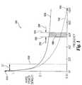
- FIG. 1shows a graph of noise power density versus frequency according to an embodiment of the present invention
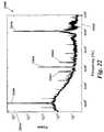
- FIG. 2shows a graph of power spectrum versus frequency according to an embodiment of the present invention
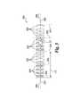
- FIG. 3shows a distribution of elements according to an embodiment of the present invention
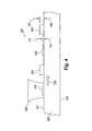
- FIG. 4shows a distribution of elements according to an embodiment of the present invention
- FIG. 5shows scanning of an element according to an embodiment of the present invention
- FIG. 6shows a distribution of elements according to an embodiment of the present invention
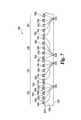
- FIG. 7shows a distribution of elements according to an embodiment of the present invention.
- FIG. 8shows a bio-CD according to an embodiment of the present invention
- FIG. 9Ashows a bio-CD according to an embodiment of the present invention.
- FIG. 9Bshows a bio-CD according to an embodiment of the present invention.
- FIG. 10Ashows a bio-CD according to an embodiment of the present invention
- FIG. 10Bshows a bio-CD according to an embodiment of the present invention
- FIG. 11shows a bio-CD according to an embodiment of the present invention
- FIG. 12shows scanning of elements according to an embodiment of the present invention
- FIG. 13shows a detection system according to an embodiment of the present invention
- FIG. 14shows a graph of time domain results of scanning a differentially encoded MD-class calibration disk
- FIG. 15shows a graph of frequency domain results of scanning a differentially encoded MD-class calibration disk
- FIG. 16shows a graph of frequency domain results of scanning a differentially encoded MD-class disk
- FIG. 17shows a graph of frequency domain results of scanning a differentially encoded MD-class disk
- FIG. 18shows a graph of frequency domain results of scanning a differentially encoded MD-class disk
- FIG. 19shows a graph of frequency domain results of scanning a differentially encoded MD-class disk
- FIG. 20shows a portion of an MD-class disk
- FIG. 21shows a graph of time domain results of scanning the disk of FIG. 20 ;
- FIG. 22shows a graph of frequency domain results of scanning the disk of FIG. 20 ;
- FIG. 23shows a graph of time domain results of scanning a PC-class disk
- FIG. 24shows a portion of a PC-class disk
- FIG. 25shows a magnified view of a portion of FIG. 24 ;
- FIG. 26shows Fourier domain results of scanning the disk of FIG. 24 ;
- FIG. 27shows a demodulated image of the of the Fourier domain results of FIG. 26 ;
- FIG. 28shows a graph of a comparison of prescan subtraction without demodulation and prescan subtraction with demodulation.
- graph 1000with frequency increasing along its x axis as indicated by x axis arrow 1020 and noise power density increasing along its y axis as indicated by its y axis arrow 1010 .
- Frequencycan be either temporal frequency (Hz) or spatial frequency (1/cm).
- Graph 1000illustrates noise power density versus frequency in the absence of a carrier frequency.
- Curve 1030illustrates the noise power density of total noise as it varies with frequency.
- Curve 1040illustrates the noise power density of 1/f noise as it varies with frequency.
- a bandwidth between frequencies 1060 and 1070is indicated by arrows BW.
- the total noise for this bandwidthis given by the area under curve 1030 labeled 1080 which represents detected noise power for a measurement taken at bandwidth BW.
- the frequency range where only static is detectableis illustrated by arrows ST.
- the frequency value of the 1/f noise kneeis illustrated by line 1050 and represents the frequency above which a signal may be detected over noise.
- graph 2000with frequency increasing along its x axis as indicated by x axis arrow 2020 and power spectrum increasing along its y axis as indicated by y axis arrow 2010 .
- the power level of 1/f noiseis illustrated by curve 2030 .
- a DC sideband signal 2040 having DC sideband center frequency 2041 , a carrier signal 2060 having carrier center frequency 2061 , and carrier sidebands 2050 and 2070 having carrier sideband center frequencies 2051 and 2071 , respectively,are also shown.
- Graph 2000illustrates one example of frequency domain detection of the molecular, cellular, or particulate content of a liquid or air sample in which an analyte binds on or in a support material to produce a periodic, quasi-periodic or harmonic modulation of phase or amplitude of an electromagnetic wave that probes the support material.
- the periodic or quasi-periodic modulationcan be in time or space, leading to a time-domain carrier frequency or a space-domain carrier frequency, by relative motion of the probe beam and support.
- the presence of the bound analyteappears as a modulation sideband of the carrier frequency.
- carrier sideband signals 2050 and 2070indicate the presence of one or more target analytes bound to analyzer molecules distributed about a support material which is probed with an electromagnetic wave in a detection system.
- the detection systempreferably includes a photodetector, or another detector responsive to electromagnetic waves, that outputs a current as described below by Equation 1:
- i ⁇ ( t )1 2 ⁇ ( 1 + cos ⁇ ⁇ ⁇ c ⁇ t ) ⁇ ( 1 + A ⁇ ⁇ cos ⁇ ⁇ ⁇ m ⁇ t )
- Equation 1has a harmonic decomposition described by Equation 2:
- i ⁇ ( t )1 2 + 1 2 ⁇ cos ⁇ ⁇ ⁇ c ⁇ t + A 2 ⁇ cos ⁇ ⁇ ⁇ m ⁇ t + A 4 ⁇ cos ⁇ ( ⁇ c + ⁇ m ) ⁇ t + A 4 ⁇ cos ⁇ ( ⁇ c - ⁇ m ) ⁇ t
- Equation 2describes a DC sideband at ⁇ m , a carrier band at ⁇ c , and two carrier sidebands at ⁇ c ⁇ m and ⁇ c + ⁇ m which correspond to DC sideband 2040 , a carrier 2060 , and sidebands 2050 and 2070 as shown in graph 2000 .
- tis time
- i(t)is detector output current as a function of time
- ⁇ cis carrier angular frequency
- ⁇ mthe modulation angular frequency
- Ais the envelope amplitude.
- detector outputcould be a voltage, another electrical signal, an optical signal, or a magnetic signal, for example, or some combination of these and/or other outputs.
- FIG. 3there is shown a distribution of elements 3000 including elements 3010 and 3020 .
- Elements 3010 and 3020are distributed about reading pathway 3004 which is defined on a substrate.
- dashed lines 3030 , 3040 , 3050 , 3060 , and 3070elements 3010 and 3020 are arranged in alternating groups of four. As shown by ellipses 3006 and 3008 this pattern can continue beyond the segment illustrated in FIG. 3 with the groups of four elements alternating as described above.
- a unit cellincludes a group of four elements 3010 and a group of four elements 3020 as is indicated by arrow UC between dashed lines 3030 and 3050 .
- Scanning footprint SFtravels along reading pathway 3004 to scan the distribution of elements 3000 .
- Additional embodimentsinclude alternating groups of different numbers, for example, one, two, three, five or more, and corresponding different sizes of unit cells.
- Elements 3010include specific analyzer molecules which selectively bind with a target analyte and elements 3020 include nonspecific analyzer molecules which do not selectively bind with a target analyte but may exhibit similar binding properties with respect to other molecules.
- elements 3010include specific antibodies immobilized about their surfaces, for example, as a monolayer, fractional monolayer, partial monolayer, or near monolayer, and elements 3020 include similarly immobilized nonspecific antibodies.
- the specific antibodycould be goat anti-mouse IgG (the antibody to the mouse protein produced by a goat) and the nonspecific antibody could be goat anti-rat IgG (the antibody to an analogous rat protein produced by a goat).
- the goat anti-mouse IgGwill selectively bind the mouse protein while the goat anti-rat IgG will not bind with it or will have a substantially lesser binding affinity, however, both IgGs exhibit similar nonspecific background binding with molecules other than the target analyte.
- the non-specific proteincould be a non-IgG, for example, casein or bovine serum albumin (BSA).
- the specific analyzer moleculescould be a cDNA that is complimentary to the target DNA, and the non-specific group could be a statistically similar, but not identical, cDNA.
- Additional embodiments calinclude specific and non-specific aptamers. A variety of other specific and nonspecific antibody pairs may also be used, including those exhibiting varying degrees of similarity in nonspecific background binding and those not exhibiting similar nonspecific background binding.
- combinations of specific and nonspecific analyzer molecules other than antibodiesmay also be used.
- nonspecific analyzer moleculesmay be omitted entirely in which case elements 3020 would not include immobilized molecules.
- Distribution of elements 3000is one example of differential encoding or envelope modulation of bimolecular information.
- distribution of elements 3000is on a bio-CD where elements 3010 and 3020 are interferometric microstructures formed on a surface of the bio-CD, and reading pathway 3004 is one of a number of a substantially concentric circular tracks.
- elements 3010 on the trackare active (carrying a specific biological analyzer molecule) and elements 3020 are inactive (carrying nonspecific molecules, no molecules, or inert molecules that may be comparable in size with the analyzer molecule).
- the carrier frequencycorresponds to the positioning of each individual one of elements 3010 and 3020
- the detection frequencycorresponds to the repeat period of the unit cell UC which is every eight elements.
- the detection frequencyis equal to one-eighth of the carrier frequency.
- the carrier frequencyis approximately 100 kHz and the detection frequency is approximately 12.5 kHz.
- a wide variety of other bimolecular platforms, scanning rates, and element distributionsincluding, for example, those described herein, are contemplated and can result in a variety of other carrier frequencies and detection frequencies.
- an optical detection systemincluding two phase-locked loops in series, with the front end referenced to the carrier frequency, and the back end referenced to the unit cell can be used to scan a bio-CD having distribution of elements 3000 with a laser.
- Differential encoding of distribution of elements 3000can preferably reduce susceptibility to laser intensity drift or disk wobble by subtracting out these and other system drifts and biases, and can preferably directly subtract non-specific background binding, for example if the off region is printed with nonspecific antibody.
- One example of a detection system according to a preferred embodiment of the present inventioncan be found in U.S. Pat. No. 6,685,885 which is hereby incorporated by reference. This detection system could also be any other detection system responsive to electromagnetic waves including for example those described elsewhere herein.
- phase quadrature interferometric techniquesinclude the micro-diffraction quadrature class (“MD-class”) and adaptive optic quadrature class (“AO-class”) as described in U.S. application Ser. No. 10/726,772 filed on Dec. 3, 2003 entitled “Adaptive Interferometric Multi-Analyte High-Speed Biosensor” (published on Aug. 26, 2004 as U.S. Pub. No. 2004/0166593), the contents of which are incorporated herein by reference.
- phase quadrature interferometric techniquesinclude the phase-contrast quadrature class (“PC-class”) as described in U.S. Provisional Patent Application No.
- further embodiments of the present inventioninclude detection systems adapted to utilize surface plasmon resonance or SPR, fluorescence, resonance and other techniques in which high frequency modulation in time or space originates from analyte bound to a solid support with a spatial frequency that is scanned to produce a sideband indicating the presence of the analyte.
- detection platforms for use in these and other detection systemswhich include distributions of targets including analyzer molecules which produce sideband signals that depend upon modulation indicative of the presence of an analyte.
- a biosensor platform 4000including a substrate 4030 having an upper surface 4010 and lower surface 4020 .
- Interferometric elements 4040 , 4050 , 4060 , and 4070are formed on the upper surface 4010 of substrate 4030 .
- Platform 4000may also include additional interferometric elements in addition to those shown in the portion of platform 4000 illustrated in FIG. 4 .
- a laser beam 4002 having wavelength ⁇scans the interferometric elements 4040 , 4050 , 4060 , and 4070 in the direction indicated by arrow DM.
- Elements 4040 and 4050include specific analyzer molecules immobilized about their scanned surfaces and elements 4060 and 4070 include nonspecific analyzer molecules immobilized about their scanned surfaces.
- biosensor platform 4000is another example of differential encoding according to a preferred embodiment of the present invention.
- platform 4000is a micro-diffraction bio-CD and elements 4040 , 4050 , 4060 , and 4070 are radial spokes distributed about the surface of the bio-CD.
- Platform 4000can also be any of various other biosensor platforms including, for example, those described herein.
- Biosensor platform 4000is one example of carrier suppression according to a preferred embodiment of the present invention.
- Elements 4060 and 4040have a height illustrated by arrows HA and elements 4050 and 4070 have a height illustrated by arrows HB.
- Height HAis about ⁇ /8 and height HB is about 3 ⁇ /8.
- Successive scanning of elements alternating between height HA and HBflips the phase quadratures detected for successive elements. This results in a modulation at about twice the amplitude as compared to a platform having interferometric elements with substantially uniform element heights.
- the carrieris suppressed by an approximately ⁇ phase difference between phase quadrature signals detected for successive elements. Carrier suppression may be useful in a variety of circumstances.
- carrier noisecan impact detection.
- carrier sidebands overlap with the carriercarrier noise can also impact detection.
- Carrier wave suppressioncan preferably increase the ratio of signal to noise. Complete carrier suppression or double sideband detection may be used to improve the signal to noise ratio of detection in these and other situations. Partial carrier suppression may also improve the signal to noise ratio of detection in these and other situations.
- Carrier wave suppressioncan also be accomplished in other manners, for example, fabrication of disk structures and reflectivities relative to beam width, through use of a clipper circuit that clips the high signal detected from a land of a detection platform, or through use of a filter, for example a band stop filter.
- element 5010is a gold microdiffraction element placed on a partially reflecting substrate. This embodiment allows carrier suppression by the total power reflected from the element being equal to the total power reflected under the condition of quadrature which removes the large modulation caused by the approximately 50% amplitude modulation of a micro diffraction bio-CD. This effect can be illustrated through the following equations.
- the total electrical (far) fieldis given by Equation 3:
- E TE 0 A ⁇ [ r L ⁇ A L + r r ⁇ A r ⁇ e i ⁇ ⁇ ⁇ ]
- Equation 4The total reflected intensity is given by Equation 4:
- I TE 0 2 A ⁇ [ R L ⁇ A L 2 + R r ⁇ A r 2 + 2 ⁇ ⁇ r L ⁇ r r ⁇ A L ⁇ A r ⁇ cos ⁇ ⁇ ⁇ ]
- I ris the total reflected intensity
- I Lis the intensity reflected by land
- I Ois the incident reflected intensity
- I Qis the reflected intensity under a condition of quadrature
- E ois the reflected field
- Ais the total area
- a Lis area 5021
- a ris area 5011
- a Lis A L divided by the area of the beam footprint
- a Ris A L divided by the area of the element 5010 intersecting element 5020
- R Lis
- R ris
- ⁇is the phase difference between reflected components of the laser.
- a biosensor platform 6000including substrate 6030 having an upper surface 6010 and a lower surface 6020 .
- Upper surface 6010includes analyzer molecules 6040 , 6050 , 6060 , 6070 , 6080 and 6090 immobilized about surface 6010 .
- Analyzer molecules 6040 , 6060 , and 6080are specific analyzer molecules for selectively binding a particular analyte and analyzer molecules 6050 , 6070 and 6090 are nonspecific analyzer molecules.
- the specific and nonspecific analyzer moleculescan be, for example, the same or similar to those described elsewhere herein.
- FIG. 6shows one example of an alternating pattern of specific and nonspecific analyzer molecules.
- Laser beam 6002scans the analyzer molecules in the direction indicated by the arrow DM which is preferably accomplished by rotating the platform 6000 but could also be accomplished by other movement of platform 6000 or by movement of beam 6002 .
- platform 6000is a phase contrast bio-CD or an adaptive optical bio-CD and analyzer molecules 6040 , 6050 , 6060 , 6070 , 6080 and 6090 are radial spokes or other patterns of analyzer molecules, however, platform 6000 could also be another kind of bio-CD or other platform including, for example, those described elsewhere herein.
- signal phase modulationdepends only upon the binding differences between the specific and nonspecific analyzer molecules. For example, nonspecific binding that is common to both the types of analyzer molecules is not imparted onto the signal beam or has minimal impact on the signal beam.
- the detected signalis therefore independent of nonspecific binding.
- differential encodingincluding carrier wave suppression and double sideband detection.
- a biological analyzer platform 7000including substrate 7030 including upper surface 7010 and lower surface 7020 .
- Interferometric elements 7070are distributed about upper surface 7010 and are spaced apart by gaps 7060 .
- Interferometric elements 7070include specific biological analyzer molecules 7040 and nonspecific biological analyzer molecules 7050 immobilized about their surfaces which can be the same or similar to those described elsewhere herein.
- Groups of the interferometric elements and analyzer molecules 7090 and 7091are also shown. Groups 7090 and 7091 have patterns of specific and nonspecific analyzer molecules that are at spatial frequencies with a ⁇ phase difference, that is, the positions of specific and nonspecific analyzer molecules are flipped between groups 7090 and 7091 .
- Platform 7000is preferably an adaptive optical bio-CD, however, platform 6000 could also be any other type of biosensor platform or another type of bio-CD including, for example, those described elsewhere herein.
- phase flipping of the carrieris that the carrier is suppressed in the power spectrum and the modulation due to binding of a specific analyzer molecule to the specific antibodies is detectable at carrier sidebands.
- differential encodingincluding carrier wave suppression and double sideband detection.
- modulated signalsare detected within a detection bandwidth ⁇ f d .
- Narrow bandwidthsreject more noise, but the detection bandwidth should preferably not be smaller than the signal bandwidth, otherwise a part of the signal is rejected with the noise.
- Equation 13The signal bandwidth ⁇ f s is described by Equation 13:
- Equation 14The relative signal bandwidth ⁇ f rel is described by Equation 14:
- ⁇ ⁇ ⁇ f rel⁇ ⁇ ⁇ f f carrier
- Equation 14For a single continuous track around a circumference, the relative bandwidth ⁇ f rel is described by Equation 14:
- ais the area of a well
- ris radius
- drradial thickness of a well
- ⁇angular position
- d ⁇well arc length
- Ais the area of the annular region between radii R 2 and R 1
- Nnumber of wells
- Sis the number of segments
- R 1is the inner radius
- R 2is the outer radius.
- Bio-CD 8000is a 100 mm diameter disk or silicon wafer, however, any other dimension disk, wafer chip or other substrate or platform could also be used.
- Bio-CD 8000includes sectors 8001 , 8002 , 8003 , 8004 , 8005 , 8006 , 8007 , 8008 , 8009 , 8010 , 8011 , 8012 , 8013 , 8014 , 8015 , and 8016 .
- Bio-CD 8000further includes substantially concentric tracks of wells 8021 , 8022 , 8023 , 8024 , 8025 , 8026 , 8027 , and 8028 .
- Inner Track Radius Radial Thickness dr Track Number(millimeters) (millimeters) 8028 20 6.56 8027 26.56 4.94 8026 31.50 3.60 8025 35.10 3.39 8024 38.50 3.13 8023 41.63 2.93 8022 44.56 2.76 8021 47.33 2.62
- Bio-CD 8000is one example of an equal area well layout according to the present invention.
- layoutsare used which bring the aspect ratio of arc length and radial thickness closer to unity which simplifies fabrication.
- Fabrication of this and other embodiments of the present inventioncan include particular features for various classes of bio-CDs.
- a micro-diffraction bio-CDcan have radial spokes fabricated from gold across the entire disk, and wells defined by hydrophobic dams.
- a pin plotter or ink-jet printer modified from biochip array printerscan be used to deposit an equal amount of analyzer molecules into each well.
- Different antibodiescan be deposited which then self-immobilize on thiolated gold.
- gel printingcan be used.
- spokescan be printed as inert protein, dams can be put into place and antibody deposited into the wells by pin array plotters or protein spotters.
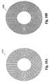
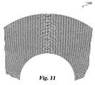
- bio-CDs 9000 A, 9000 B, 10000 A, 10000 B, and 11000according to embodiments of the present invention where the wells are of equal area.
- the radial width of each wellis constant which simplifies design of the protein plotter, and optimal use of real-estate is made.
- This embodimentrequires a carrier spoke number C to vary with radius, also causing the carrier frequency to vary with radius (for constant angular velocity). The relation of the spoke number is given by Equation 21:
- wis the beam waist.
- the carrier frequenciesare 300 kHz and 800 kHz, respectively.
- Equation 24The radial widths and angular widths are given by Equation 24:
- the well in FIGS. 9A and 9B areasare approximately 0.6 cm 2 .
- a variety of other disks with equal area wells and unequal well areasare also contemplated. In general, larger aspect ratios have narrower detection bandwidth, but more tracks with smaller track pitches.
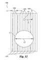
- Targets 12000are a periodically alternating pattern of targets including specific antibodies 12010 and targets including nonspecific antibodies or not including antibodies 12020 . Specific and nonspecific antibodies are being immobilized about a substrate, for example, as described herein. After exposure to a sample including a specific target analyte, targets 12010 have the analyte bound to their analyzer molecules while targets 12020 exhibit little or no binding of the specific analyte.
- the period of the alternating patternis shown by arrows LL, and the spatial frequency of the pattern is inversely proportional to its period as shown by Equation 25:
- V spatial1 ⁇
- ⁇is the spatial periodicity and ⁇ spatial is the spatial frequency.
- a scanning footprintsuch as a laser spot.
- the scanning footprintcould be, for example, focused laser spot vv which has a width w o less than spatial periodicity ⁇ (preferably w o ⁇ ) and moves relative to the targets 12000 with a velocity in the direction indicated by arrow v.
- fis the carrier frequency of phase or amplitude modulation.
- the scanning footprintcould also be, for example, broad area laser spot z which has a width w o greater than spatial periodicity ⁇ (preferably w o >> ⁇ ) and can be stationary or can move relative to the targets 12000 with a velocity V in the direction indicated by arrow v.
- ⁇spatial periodicity
- ⁇is the illumination wavelength
- ⁇is the spatial period
- the foregoing examplesillustrate how spatial frequencies on a scanning platform, for example a chip or disk, can be converted into temporal frequencies in a laser scanning system, and how the two types of frequencies can be combined when a laser probes more than one target on the platform.
- detection system 13000which includes detector 13010 and detector 13020 .
- Detectors 13010 and 13020could be any detectors for detecting electromagnetic waves, for example optical detectors.
- System 13000further includes probe beam 13030 which can be a focused probe beam or a broad area probe beam.
- Probe beam 13030scans targets 13040 which move relative to beam 13030 with a relative velocity in the direction indicated by arrow RV.
- the scanning targets 13040 by beam 13030results in a transmitted or reflected mode 13012 and a diffracted mode 13022 .
- Mode 13012is directed to detector 13010 and mode 13022 is directed to detector 13020 .
- Reference beam 13023is directed to detector 13010 and reference beam 13023 is directed to detector 13020 .
- Reference beam 13023is preferably maintained in a condition of phase quadrature relative to the transmitted mode 13012 .
- Reference beam 13033is preferably maintained in a condition of phase quadrature relative to diffracted mode 13022 .
- System 13000also includes beam splitters 13011 and 13021 which could also be adaptive optical beam combiners. Having a reference wave that is in phase quadrature with detected signal allows a small shift in the phase modulation of the signal to linearly proportional change in detected intensity allowing signal modulation per bound analyte molecule to be maximized.
- Reference beams 13033 and 13023can be added before photodetectors or can be combined adaptively with signals.
- Reference beams 13033 and 13023can arise from a diffracted spatial mode, for example, in the case of wavefront splitting, from free space, or from partial reflections, for example, in the case of amplitude splitting. It is also contemplated that detection system 13000 could include only one or the other of detectors 13010 and 13020 and their related beams and modes.
- FIG. 14there is shown graph 14000 with time increasing along its x axis as indicated by x axis arrow 1420 and signal intensity (voltage) increasing along its y axis as indicated by y axis arrow 14010 .
- Graph 14000further shows signal 14030 which is a voltage signal that varies with time.
- Signal 14030results from the scanning of an MD-class calibration disk which was fabricated with 1024 gold spokes deposited radially on a dielectric substrate. The average (mean) spoke height was 80 nm. Of the 1024 spokes, 512 spokes were below the average height, 512 spokes were above the average height, and the spokes alternated between those above the average height and those below the average height.
- Scanning the MD-class calibration diskproduced signal 14030 which includes a series of alternating local minima 14031 and 14032 corresponding to and indicating the two spoke heights.
- the signal intensity difference between the alternating local minima 14031 and 14032is illustrated by arrow 14040 and corresponds to a height difference of about 30 nm between alternating spokes. This height difference is representative of the height difference cause by certain target analytes to analyzer molecules.
- the signal level corresponding to the average spoke height of about 80 nmis indicated by dashed line 14050 .
- the MD-class calibration diskthus provides a simulation of a differential encoding scheme whereby every other alternating spoke includes analyzer molecules that bind a target analyte and can be compared to a reference spoke. The fast relative comparison between the two types of spokes allows for significant noise reduction.
- graph 15000with frequency increasing along its x axis as shown by x axis arrow 15020 and power increasing logarithmically along its y axis as shown by y axis arrow 15010 .
- Graph 15000shows the frequency domain results of the scanning of the MD-class calibration disk described above in connection with FIG. 14 .
- Graph 15000shows carrier signal 15030 at 200 kHz, sideband signal 15031 at 100 kHz, and sideband signal 15032 at 300 kHz.
- a strong 1/f noise peak 15040is present at zero frequency, and a significantly suppressed noise floor is present at the frequencies of carrier and sideband signals 15030 , 15031 and 15032 .
- the noise suppression by operating at this scanning rateis over 60 dB or 3 orders of magnitude better signal to noise ratio when compared to a static measurement at DC (zero frequency). This is a fundamental advantage to high speed repetitive sampling according to certain embodiments of the present invention.
- graph 16000with frequency increasing along its x axis as shown by x axis arrow 16020 and power increasing along its y axis as shown by y axis arrow 16010 .
- Graph 16000shows an example of protein side-band detection for an MD-class disk having proteins (in this case antibody IgG molecules) immobilized on a 1024-spoke disk with 64 segments composed of 8 elements with protein and 8 elements without. This created a disk with an alternating pattern of 8 gold spokes carrying protein followed by 8 bare gold spokes. This pattern repeated for a total of 64 segments each with a total of 16 elements divided into 8 with protein and 8 without.
- proteinsin this case antibody IgG molecules
- the proteinswere patterned using a polydimethylsiloxane (PDMS) stencil on the disk.
- a control track which did not include printed proteinwas also included on the disk.
- the results of scanning the control trackare indicated by dotted line 16060 and the results of scanning a track including the patterned protein are indicated by line 16050 .
- Graph 16000shows 16030 the 1/f noise at DC and two DC sideband signals 16031 and 16032 .
- a carrier frequency signal(not shown) is present at about 100 kHz.
- the presence of proteinis detected as a 1/64 harmonic of the carrier frequency at about 1.6 kHz as shown by signal 16032 and also by signal 16031 at about ⁇ 1.6 kHz.
- a second harmonic signal 16034 and 16033is also present at 1/32 the carrier frequency and is caused by slight asymmetry in the deposition of the proteins.
- a comparison of protein track signal 16050 and signal 16060 of a control track containing no proteinillustrates the strong effect of the protein in producing sideband signals with a 20:1 signal to noise ratio as indicated by arrow 16040 .
- graph 17000with frequency increasing along its x axis as shown by x axis arrow 17020 and power spectrum increasing logarithmically along its y axis as shown by y axis arrow 17010 .
- Graph 17000presents average values for scanning of six tracks of the MD-class disk which is described above in connection with FIG. 16 .
- Graph 17000shows a comparison of 1/64 harmonic signal 17040 at about 1.6 kHz, which is generated by and indicates the presence of protein, and carrier signal 17030 .
- the protein modulationis about 4.6% of the carrier wave, which is consistent with a monolayer of immobilized protein.
- graph 18000with frequency increasing along its x axis as shown by x axis arrow 18020 and power spectrum increasing logarithmically along its y axis as shown by y axis arrow 18010 .
- every carrier harmonicincludes two side-bands.
- fundamental carrier harmonic 18030which is at about 80 kHz includes sidebands 18031 and 18032 .
- Sidebands 18031 and 18032are small peaks above and below the harmonic carrier frequency 18030 which indicate the presence of the protein. Every other carrier harmonic also has two associated sidebands.
- graph 19000with frequency increasing along its x axis as shown by x axis arrow 19020 and power spectrum increasing logarithmically along its y axis as shown by y axis arrow 19010 .
- Graph 19000shows carrier frequency harmonics 19030 A (which is the first carrier harmonic 18030 at about 80 kHz described above in connection with FIG. 18 ), 19030 B, 19030 C, 19030 D, 19030 E, 19030 F, and 19030 G.
- Each carrier harmonicincludes protein sidebands, though the wide frequency range of the graph 1900 makes it difficult to see the protein sidebands for all the harmonics.
- Line 19050shows the approximate midpoint of the noise floor roll off.
- Disk 20000is a half-harmonic differentially encoded MD-class disk which was created using photolithography to immobilize protein on every alternating spoke. During this process half the spokes were covered by photo-patterned photoresist while the other half were exposed to protein. The photoresist was then removed to uncover bare gold spokes. This results in a disk where protein is immobilized on every alternating spoke as shown by lines 20010 (indicating deposition of specific antibody) and 20020 (indicating no deposition of antibody, or deposition of a non-specific antibody). The width of each protein deposit is about 20 microns as indicated by arrows SW.
- This half-harmonic differential encoding in which every alternating spoke carries proteinresults in the highest signal-to-noise ratio being attained. This provides for the highest-frequency differencing measurements, and also boosts the total protein signal when the zero-frequency upper sideband and the carrier frequency lower side-band merge into a single sideband half way between DC and the fundamental carrier frequency.
- graph 21000with time increasing along its x axis as shown by x axis arrow 21020 and voltage increasing along its y axis as shown by y axis arrow 21010 .
- Graph 21000shows the detected time trace 21030 from a 512 differential encoded disk.
- Trace 21030shows an alternating pattern between the bare and protein-carrying spokes as indicated by the minimum points trace 21030 which alternate in amplitude at the rate of a half harmonic signal 21040 .
- graph 22000with frequency increasing along its x axis as shown by x axis arrow 22020 and power spectrum increasing logarithmically along its y axis as shown by y axis arrow 22010 .
- Graph 22000shows the frequency domain side band effect of the disk described above in connection with FIG. 21 .
- the half-frequency harmonic protein signal 22040is strong and occurs near the frequency of lowest noise between DC signal 22050 and the first carrier signal 22030 .
- the DC sideband and first carrier sidebandshave merged at the half-frequency harmonic protein signal 22040 .
- the protein signal 22050itself has sidebands 22041 and 22042 caused by slight asymmetries in the protein printing. The signal-to-noise ratio is greatest in this situation where the noise floor is lowest.
- detection of protein at signal 22040represents the optimal performance condition for carrier sideband detection on the MD-class disk described above.
- graph 23000with frequency increasing along its x axis as shown by x axis arrow 23020 and power spectrum increasing logarithmically along its y axis as shown by y axis arrow 23010 .
- Graph 23000shows the power spectrum for an embodiment of a PC-class disk with a periodic pattern of protein on a dielectric disk with no other disk structure.
- Graph 23000shows DC signal 23040 and protein signal 23030 which is caused by and indicates the presence of protein.
- the carrier frequencyis attributable entirely to the protein, without any contribution from microstructures or other physical structures on the disk.
- the detection of periodic patterns of immobilized protein on a flat surfaceis one example of carrier-wave suppression that was discussed above.
- Analyzer molecule patterns on PC-class disksoffer a embodiment of side-band detection and manipulation that significantly improves the sensitivity of the bio-CD because the periodic protein patterns can themselves be modulated to form larger spatial patterns.
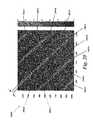
- FIG. 24there is shown a portion of a patterned protein PC-class disk 24000 according to one embodiment of the present invention.
- the radial directionis in the vertical direction the angular direction around the disk is in the horizontal direction.
- the portion of disk 24000is in a checkerboard pattern.
- Substantially rectangular areas of periodic stripes of protein 24010are alternated with substantially rectangular areas of bare disk 24020 .
- Each substantially rectangular areahas a radial distance of approximately 0.5 mm indicated by arrow RD and an angular distance of approximately 45 degrees indicated by arrow AD.
- the height of the printed protein stripesis approximately 5 nm.
- the signal resulting from scanning the PC-class diskis differential, showing only the steps up and down from the protein stripes.
- FIG. 25there is shown a magnified portion 25000 of the PC-class disk 24000 shown in FIG. 24 individual protein bands 24011 of protein regions 24010 are visible in magnified portion 25000 .
- the rectangular spatial patterns of areas 24010 and 4020 of disk 24000create sidebands on the protein peak in the power spectrum.
- the long-range spatial patternscan be detected using a sideband demodulation process conceptually similar to the demodulation of FM radio.
- the long-range protein patternsconstitute an envelope that modulates the carrier wave. By demodulation, the envelope is extracted. Because it is more slowly varying, envelope demodulation makes it possible to perform more accurate prescan subtraction.
- FIG. 26shows an isolated protein peak 26030 in the power spectrum.
- the horizontal axis 26010is temporal frequency and the vertical axis 26020 is spatial frequency along the radius of the disk.
- the sub-peaks 26031 and 26032represent the long-range envelope pattern.
- this protein peakis shifted back to DC and then Fourier-transformed back into the space domain.
- the resulting demodulated imageis shown in FIG. 27 . Only the long-range checkerboard pattern 27000 corresponding to areas 24010 and 24020 is visible, with the periodicity of the individual protein bands 24011 removed. After demodulation, subtracting a prescan becomes much more accurate.
- FIG. 28shows graph 28000 with distribution probability on the vertical axis and height in nm on the horizontal axis.
- Graph 28000shows the results of subtracting a prescan from a postscan before demodulation as distribution 28010 and performing the same subtraction after demodulation as distribution 28020 .
- the error in heightreduces from 75 pm for distribution 28010 to 20 pm for distribution 28020 with demodulation. This increased accuracy improves surface mass sensitivity by over a factor of 3 in this example.
- biosensor platformscan include a variety of biosensor platforms including those described above.
- these platformsinclude bio-CDs such as micro-diffraction bio-CDs, adaptive-optical bio-CDs, phase-contrast bio-CDs, and others. Details relating to these various classes of bio-CDs can be found, for example, in the aforementioned patents and patent applications.
- bio-CDssuch as micro-diffraction bio-CDs, adaptive-optical bio-CDs, phase-contrast bio-CDs, and others. Details relating to these various classes of bio-CDs can be found, for example, in the aforementioned patents and patent applications.
- These platformsfurther include bio-chips, immunological chips, gene chips, DNA arrays, platforms used in connection with fluorescence assays and other platforms and substrates supporting planar arrays including analyzer molecules including, for example, those described herein.
- Various embodiments according to the present inventioncan include a variety of analyzer molecules useful in detecting the presence or absence of a variety of target analytes in a solution to be tested.
- these analyzer moleculescan include antibodies or immunoglobulins, antigens, DNA fragments, cDNA fragments, aptameres, peptides, proteins, and other molecules.
- Various embodiments according to the present inventioncan include combinations of one or more of the foregoing and other types of analyzer molecules known to a person of ordinary skill in the art arranged, for example, in a planar array.
- Such techniquesinclude interferometry, including surface normal interferometry techniques, and preferably phase quadrature interferometry techniques where one detected optical mode differs in phase from another by about ⁇ /2 plus or minus about twenty percent or an odd integer multiple thereof, and/or self referencing interferometry techniques where a reference wave is generated locally with respect to a signal wave so that the reference and signal waves experience common aberrations and path length changes and thus maintain a constant relative phase without the need for active stabilization of different light paths, florescence techniques and platforms, resonance techniques and platforms, and other techniques and platforms.
Landscapes
- Health & Medical Sciences (AREA)
- Immunology (AREA)
- Life Sciences & Earth Sciences (AREA)
- Chemical & Material Sciences (AREA)
- Engineering & Computer Science (AREA)
- Biochemistry (AREA)
- Hematology (AREA)
- General Physics & Mathematics (AREA)
- Physics & Mathematics (AREA)
- Pathology (AREA)
- Analytical Chemistry (AREA)
- Biomedical Technology (AREA)
- Urology & Nephrology (AREA)
- Molecular Biology (AREA)
- General Health & Medical Sciences (AREA)
- Microbiology (AREA)
- Cell Biology (AREA)
- Biotechnology (AREA)
- Food Science & Technology (AREA)
- Medicinal Chemistry (AREA)
- Investigating Or Analysing Materials By Optical Means (AREA)
- Investigating, Analyzing Materials By Fluorescence Or Luminescence (AREA)
Abstract
Description
IL=I0RL
IQ=IL
RLaL2+Rrar2=RL
ΔωxΔτ=1
fcarrier=Nfdisk
where a is the area of a well, r is radius, dr is radial thickness of a well, θ is angular position, dθ is well arc length, A is the area of the annular region between radii R2and R1, N is number of wells, S is the number of segments, R1is the inner radius, and R2is the outer radius.
| Inner Track Radius | Radial Thickness dr | |
| Track Number | (millimeters) | (millimeters) |
| 8028 | 20 | 6.56 |
| 8027 | 26.56 | 4.94 |
| 8026 | 31.50 | 3.60 |
| 8025 | 35.10 | 3.39 |
| 8024 | 38.50 | 3.13 |
| 8023 | 41.63 | 2.93 |
| 8022 | 44.56 | 2.76 |
| 8021 | 47.33 | 2.62 |
a=rdθdr=A/N
rdθ=ardr
f=V·ν
Claims (9)
Priority Applications (1)
| Application Number | Priority Date | Filing Date | Title |
|---|---|---|---|
| US12/466,943US8298831B2 (en) | 2005-02-01 | 2009-05-15 | Differentially encoded biological analyzer planar array apparatus and methods |
Applications Claiming Priority (5)
| Application Number | Priority Date | Filing Date | Title |
|---|---|---|---|
| US64907005P | 2005-02-01 | 2005-02-01 | |
| US64872405P | 2005-02-01 | 2005-02-01 | |
| US75517705P | 2005-12-30 | 2005-12-30 | |
| US11/345,566US20070023643A1 (en) | 2005-02-01 | 2006-02-01 | Differentially encoded biological analyzer planar array apparatus and methods |
| US12/466,943US8298831B2 (en) | 2005-02-01 | 2009-05-15 | Differentially encoded biological analyzer planar array apparatus and methods |
Related Parent Applications (1)
| Application Number | Title | Priority Date | Filing Date |
|---|---|---|---|
| US11/345,566DivisionUS20070023643A1 (en) | 2005-02-01 | 2006-02-01 | Differentially encoded biological analyzer planar array apparatus and methods |
Publications (2)
| Publication Number | Publication Date |
|---|---|
| US20090263913A1 US20090263913A1 (en) | 2009-10-22 |
| US8298831B2true US8298831B2 (en) | 2012-10-30 |
Family
ID=37693293
Family Applications (2)
| Application Number | Title | Priority Date | Filing Date |
|---|---|---|---|
| US11/345,566AbandonedUS20070023643A1 (en) | 2005-02-01 | 2006-02-01 | Differentially encoded biological analyzer planar array apparatus and methods |
| US12/466,943Expired - Fee RelatedUS8298831B2 (en) | 2005-02-01 | 2009-05-15 | Differentially encoded biological analyzer planar array apparatus and methods |
Family Applications Before (1)
| Application Number | Title | Priority Date | Filing Date |
|---|---|---|---|
| US11/345,566AbandonedUS20070023643A1 (en) | 2005-02-01 | 2006-02-01 | Differentially encoded biological analyzer planar array apparatus and methods |
Country Status (1)
| Country | Link |
|---|---|
| US (2) | US20070023643A1 (en) |
Families Citing this family (9)
| Publication number | Priority date | Publication date | Assignee | Title |
|---|---|---|---|---|
| US20070023643A1 (en)* | 2005-02-01 | 2007-02-01 | Nolte David D | Differentially encoded biological analyzer planar array apparatus and methods |
| JP2009527739A (en)* | 2006-02-16 | 2009-07-30 | パーデュー・リサーチ・ファウンデーション | Improved quadrature interference detection with inline quadrature and antireflection |
| US20080230605A1 (en)* | 2006-11-30 | 2008-09-25 | Brian Weichel | Process and apparatus for maintaining data integrity |
| US20080144899A1 (en)* | 2006-11-30 | 2008-06-19 | Manoj Varma | Process for extracting periodic features from images by template matching |
| US7522282B2 (en)* | 2006-11-30 | 2009-04-21 | Purdue Research Foundation | Molecular interferometric imaging process and apparatus |
| WO2008089495A2 (en) | 2007-01-19 | 2008-07-24 | Purdue Research Foundation | System with extended range of molecular sensing through integrated multi-modal data acquisition |
| CA2681722A1 (en)* | 2007-03-26 | 2008-10-02 | Purdue Research Foundation | Method and apparatus for conjugate quadrature interferometric detection of an immunoassay |
| BRPI0822092A8 (en)* | 2007-12-20 | 2016-03-22 | Koninklijke Philips Electronics Nv | MICROELECTRONIC SENSOR DEVICE FOR THE EXAMINATION OF TARGET PARTICLES, METHOD FOR THE EXAMINATION OF TARGET PARTICLES, AND, USE OF THE MICROELECTRONIC SENSOR DEVICE |
| WO2013067448A2 (en) | 2011-11-03 | 2013-05-10 | Vca Antech Inc. | Compositions and methods to detect various infectious organisms |
Citations (181)
| Publication number | Priority date | Publication date | Assignee | Title |
|---|---|---|---|---|
| US3796495A (en) | 1972-05-30 | 1974-03-12 | Zenith Radio Corp | Apparatus and methods for scanning phase profilometry |
| US4537861A (en) | 1983-02-03 | 1985-08-27 | Elings Virgil B | Apparatus and method for homogeneous immunoassay |
| US4741620A (en) | 1982-10-08 | 1988-05-03 | National Research Development Corporation | Irradiative probe system |
| US4876208A (en) | 1987-01-30 | 1989-10-24 | Yellowstone Diagnostics Corporation | Diffraction immunoassay apparatus and method |
| US4899195A (en) | 1988-01-29 | 1990-02-06 | Ushio Denki | Method of exposing a peripheral part of wafer |
| US4975217A (en) | 1981-07-20 | 1990-12-04 | Kimberly-Clark Corporation | Virucidal composition, the method of use and the product therefor |
| USRE33581E (en) | 1984-06-25 | 1991-04-30 | Immunoassay using optical interference detection | |
| US5122284A (en) | 1990-06-04 | 1992-06-16 | Abaxis, Inc. | Apparatus and method for optically analyzing biological fluids |
| US5155549A (en) | 1990-10-25 | 1992-10-13 | The Research Of State University Of New York | Method and apparatus for determining the physical properties of materials using dynamic light scattering techniques |
| US5413939A (en) | 1993-06-29 | 1995-05-09 | First Medical, Inc. | Solid-phase binding assay system for interferometrically measuring analytes bound to an active receptor |
| US5478750A (en) | 1993-03-31 | 1995-12-26 | Abaxis, Inc. | Methods for photometric analysis |
| US5478527A (en) | 1990-05-17 | 1995-12-26 | Adeza Biomedical Corporation | Highly reflective biogratings |
| US5494829A (en) | 1992-07-31 | 1996-02-27 | Biostar, Inc. | Devices and methods for detection of an analyte based upon light interference |
| US5497007A (en) | 1995-01-27 | 1996-03-05 | Applied Materials, Inc. | Method for automatically establishing a wafer coordinate system |
| US5545531A (en) | 1995-06-07 | 1996-08-13 | Affymax Technologies N.V. | Methods for making a device for concurrently processing multiple biological chip assays |
| US5581345A (en) | 1990-12-03 | 1996-12-03 | Nikon Corporation | Confocal laser scanning mode interference contrast microscope, and method of measuring minute step height and apparatus with said microscope |
| US5602377A (en) | 1995-03-01 | 1997-02-11 | Metanetics Corporation | Bar code dataform scanning and labeling apparatus and method |
| US5621532A (en) | 1994-12-08 | 1997-04-15 | Nikon Corporation | Laser scanning microscope utilizing detection of a far-field diffraction pattern with 2-dimensional detection |
| US5629044A (en) | 1995-01-31 | 1997-05-13 | Nobler Technologies, Inc. | Compact disc coating and handling system |
| US5653939A (en) | 1991-11-19 | 1997-08-05 | Massachusetts Institute Of Technology | Optical and electrical methods and apparatus for molecule detection |
| US5700046A (en) | 1995-09-13 | 1997-12-23 | Silicon Valley Group, Inc. | Wafer gripper |
| US5717778A (en) | 1993-02-26 | 1998-02-10 | Chu; Albert E. | Optical specimen analysis system and method |
| US5736257A (en) | 1995-04-25 | 1998-04-07 | Us Navy | Photoactivatable polymers for producing patterned biomolecular assemblies |
| US5781649A (en) | 1996-04-15 | 1998-07-14 | Phase Metrics, Inc. | Surface inspection of a disk by diffraction pattern sampling |
| US5786226A (en) | 1995-03-16 | 1998-07-28 | Boehringer Mannheim Gmbh | Quantitative transmission spectroscopy using sample carriers with nets |
| US5837475A (en) | 1997-01-30 | 1998-11-17 | Hewlett-Packard Co. | Apparatus and method for scanning a chemical array |
| US5844871A (en) | 1996-02-13 | 1998-12-01 | Nec Corporation | Optical disk track counting apparatus and method for improved track access |
| US5843767A (en) | 1993-10-28 | 1998-12-01 | Houston Advanced Research Center | Microfabricated, flowthrough porous apparatus for discrete detection of binding reactions |
| US5875029A (en) | 1996-01-19 | 1999-02-23 | Phase Metrics, Inc. | Apparatus and method for surface inspection by specular interferometric and diffuse light detection |
| US5883717A (en) | 1996-06-04 | 1999-03-16 | Northeastern University | Optical quadrature interferometry utilizing polarization to obtain in-phase and quadrature information |
| US5892577A (en) | 1994-09-21 | 1999-04-06 | The University Court Of The University Of Glasgow | Apparatus and method for carrying out analysis of samples |
| US5900935A (en) | 1997-12-22 | 1999-05-04 | Klein; Marvin B. | Homodyne interferometer and method of sensing material |
| US5922617A (en) | 1997-11-12 | 1999-07-13 | Functional Genetics, Inc. | Rapid screening assay methods and devices |
| US5935785A (en) | 1997-04-30 | 1999-08-10 | Motorola, Inc. | Binding assay methods |
| US5945344A (en) | 1995-06-07 | 1999-08-31 | Igen International, Inc. | Electrochemiluminescence method |
| US5945334A (en) | 1994-06-08 | 1999-08-31 | Affymetrix, Inc. | Apparatus for packaging a chip |
| US5955377A (en) | 1991-02-11 | 1999-09-21 | Biostar, Inc. | Methods and kits for the amplification of thin film based assays |
| US5968728A (en) | 1997-04-30 | 1999-10-19 | Motorola, Inc. | Molecular detection devices and methods of forming same |
| US5999262A (en) | 1996-04-19 | 1999-12-07 | Carl Zeiss Jena Gmbh | Process and apparatus for detecting structural changes of specimens |
| US6008892A (en) | 1997-05-23 | 1999-12-28 | Molecular Dynamics, Inc. | Optical substrate for enhanced detectability of fluorescence |
| US6030581A (en) | 1997-02-28 | 2000-02-29 | Burstein Laboratories | Laboratory in a disk |
| US6048692A (en) | 1997-10-07 | 2000-04-11 | Motorola, Inc. | Sensors for electrically sensing binding events for supported molecular receptors |
| US6060237A (en) | 1985-02-26 | 2000-05-09 | Biostar, Inc. | Devices and methods for optical detection of nucleic acid hybridization |
| US6071748A (en) | 1997-07-16 | 2000-06-06 | Ljl Biosystems, Inc. | Light detection device |
| US6099803A (en) | 1994-07-07 | 2000-08-08 | Nanogen, Inc. | Advanced active electronic devices for molecular biological analysis and diagnostics |
| US6110748A (en) | 1997-04-30 | 2000-08-29 | Motorola, Inc. | Optical storage medium for binding assays |
| US6121048A (en) | 1994-10-18 | 2000-09-19 | Zaffaroni; Alejandro C. | Method of conducting a plurality of reactions |
| US6143247A (en) | 1996-12-20 | 2000-11-07 | Gamera Bioscience Inc. | Affinity binding-based system for detecting particulates in a fluid |
| US6221579B1 (en) | 1998-12-11 | 2001-04-24 | Kimberly-Clark Worldwide, Inc. | Patterned binding of functionalized microspheres for optical diffraction-based biosensors |
| US6238869B1 (en) | 1997-12-19 | 2001-05-29 | High Throughput Genomics, Inc. | High throughput assay system |
| US6248539B1 (en) | 1997-09-05 | 2001-06-19 | The Scripps Research Institute | Porous semiconductor-based optical interferometric sensor |
| US6271924B1 (en) | 1998-12-29 | 2001-08-07 | Bryan Kok Ann Ngoi | Noncontact acoustic optic scanning laser vibrometer for determining the difference between an object and a reference surface |
| US6287783B1 (en) | 1999-03-18 | 2001-09-11 | Biostar, Inc. | Optical assay device and method |
| US6287850B1 (en) | 1995-06-07 | 2001-09-11 | Affymetrix, Inc. | Bioarray chip reaction apparatus and its manufacture |
| US6312961B1 (en) | 1998-05-22 | 2001-11-06 | Csem Centre Suisse D'electronique Et De Microtechnique Sa | Optical sensor using an immunological reaction and a fluorescent marker |
| US6312901B2 (en) | 1996-07-08 | 2001-11-06 | Burstein Technologies, Inc. | Spatially addressable, cleavable reflective signal elements, assay device and method |
| US6320665B1 (en) | 1998-12-29 | 2001-11-20 | Bryan Kok Ann Ngoi | Acousto optic scanning laser vibrometer for determining the dynamic properties of an object |
| US6319469B1 (en) | 1995-12-18 | 2001-11-20 | Silicon Valley Bank | Devices and methods for using centripetal acceleration to drive fluid movement in a microfluidics system |
| US6327031B1 (en) | 1998-09-18 | 2001-12-04 | Burstein Technologies, Inc. | Apparatus and semi-reflective optical system for carrying out analysis of samples |
| US20020001546A1 (en) | 1998-01-12 | 2002-01-03 | Massachusetts Institute Of Technology | Methods for screening substances in a microwell array |
| US20020008871A1 (en) | 1998-12-14 | 2002-01-24 | Annemarie Poustka | Method and device for detecting optical properties, especially luminescence reactions and refraction behavior of molecules which are directly or indirectly bound on a support |
| US6342395B1 (en) | 1998-04-22 | 2002-01-29 | The Regents Of The University Of California | Compact assay system with digital information |
| US6342349B1 (en) | 1996-07-08 | 2002-01-29 | Burstein Technologies, Inc. | Optical disk-based assay devices and methods |
| US6345115B1 (en) | 1997-08-07 | 2002-02-05 | Imaging Research, Inc. | Digital imaging system for assays in well plates, gels and blots |
| US6350413B1 (en) | 1995-02-23 | 2002-02-26 | University Of Utah Research Foundation | Integrated optic waveguide immunosensor |
| EP1189062A1 (en) | 2000-09-18 | 2002-03-20 | James J. Dr. La Clair | Method and device for identifying molecular species |
| US6368795B1 (en) | 1998-02-02 | 2002-04-09 | Signature Bioscience, Inc. | Bio-assay device and test system for detecting molecular binding events |
| US20020045276A1 (en) | 1996-04-25 | 2002-04-18 | Juan Yguerabide | Analyte assay using particulate labels |
| US6376258B2 (en) | 1998-02-02 | 2002-04-23 | Signature Bioscience, Inc. | Resonant bio-assay device and test system for detecting molecular binding events |
| US6381025B1 (en) | 1999-08-19 | 2002-04-30 | Texas Tech University | Interferometric detection system and method |
| US20020051973A1 (en) | 1999-09-17 | 2002-05-02 | Glenda C. Delenstarr | Techniques for assessing nonspecific binding of nucleic acids to surfaces |
| US6387331B1 (en) | 1998-01-12 | 2002-05-14 | Massachusetts Institute Of Technology | Method and apparatus for performing microassays |
| US20020058242A1 (en) | 1996-09-20 | 2002-05-16 | James Paul Demers | Spatially addressable combinatorial chemical arrays in cd-rom format |
| US6395562B1 (en) | 1998-04-22 | 2002-05-28 | The Regents Of The University Of California | Diagnostic microarray apparatus |
| US6395558B1 (en) | 1996-08-29 | 2002-05-28 | Zeptosens Ag | Optical chemical/biochemical sensor |
| US6403957B1 (en) | 1989-06-07 | 2002-06-11 | Affymetrix, Inc. | Nucleic acid reading and analysis system |
| US6416642B1 (en) | 1999-01-21 | 2002-07-09 | Caliper Technologies Corp. | Method and apparatus for continuous liquid flow in microscale channels using pressure injection, wicking, and electrokinetic injection |
| US20020097658A1 (en) | 2000-12-08 | 2002-07-25 | Worthington Mark O. | Multiple data layer optical discs for detecting analytes |
| US20020106661A1 (en) | 1996-07-08 | 2002-08-08 | Burstein Laboratories, Inc. | Optical disk-based assay devices and methods |
| US20020127565A1 (en) | 2000-10-30 | 2002-09-12 | Sru Biosystems, Llc | Label-free high-throughput optical technique for detecting biomolecular interactions |
| US20020151043A1 (en) | 2001-04-11 | 2002-10-17 | Gordon John Francis | Multi-parameter assays including analysis discs and methods relating thereto |
| US6469787B1 (en) | 2001-04-03 | 2002-10-22 | Ohio Aerospace Institute | Dynamic light scattering homodyne probe |
| US6483588B1 (en) | 1998-06-26 | 2002-11-19 | Carl Zeiss Jena Gmbh | Arrangement for detecting biomolecular reactions and interactions |
| US6483585B1 (en) | 1999-08-06 | 2002-11-19 | Thermo Biostar, Inc. | Instruments for analyzing binding assays based on attenuation of light by thin films |
| US20020177144A1 (en)* | 1997-12-30 | 2002-11-28 | Jose Remacle | Detection and/or quantification method of a target molecule by a binding with a capture molecule fixed on the surface of a disc |
| US6496267B1 (en) | 1999-04-05 | 2002-12-17 | Olympus Optical Co., Ltd. | Scanning microscope |
| US6496309B1 (en) | 1999-06-18 | 2002-12-17 | Genomic Solutions, Inc. | Automated, CCD-based DNA micro-array imaging system |
| US6504618B2 (en) | 2001-03-21 | 2003-01-07 | Rudolph Technologies, Inc. | Method and apparatus for decreasing thermal loading and roughness sensitivity in a photoacoustic film thickness measurement system |
| US20030026735A1 (en) | 2001-06-22 | 2003-02-06 | Nolte David D. | Bio-optical compact disk system |
| US6518056B2 (en) | 1999-04-27 | 2003-02-11 | Agilent Technologies Inc. | Apparatus, systems and method for assaying biological materials using an annular format |
| US20030035352A1 (en) | 2001-07-12 | 2003-02-20 | Worthington Mark Oscar | Optical disc system and related detecting methods for analysis of microscopic structures |
| WO2003014711A1 (en) | 2001-08-07 | 2003-02-20 | Mitsubishi Chemical Corporation | Surface plasmon resonance sensor chip, and sample analysis method and analysis apparatus using the same |
| US20030054376A1 (en) | 1997-07-07 | 2003-03-20 | Mullis Kary Banks | Dual bead assays using cleavable spacers and/or ligation to improve specificity and sensitivity including related methods and apparatus |
| US6566069B2 (en) | 1997-02-21 | 2003-05-20 | Burstein Technologies, Inc. | Gene sequencer and method for determining the nucleotide sequence of a chromosome |
| US20030112446A1 (en) | 2001-10-26 | 2003-06-19 | Benjamin Miller | Method for biomolecular sensing and system thereof |
| US6584217B1 (en) | 1995-06-05 | 2003-06-24 | E Y Laboratories, Inc. | Reflectometry system with compensation for specimen holder topography and with lock-rejection of system noise |
| US6591196B1 (en) | 2000-06-06 | 2003-07-08 | Agilent Technologies Inc. | Method and system for extracting data from surface array deposited features |
| US20030134330A1 (en) | 1999-04-15 | 2003-07-17 | Ilya Ravkin | Chemical-library composition and method |
| US20030133640A1 (en) | 2000-08-09 | 2003-07-17 | Kurt Tiefenthaler | Waveguide grid array and optical measurement arrangement |
| US6596483B1 (en) | 1999-11-12 | 2003-07-22 | Motorola, Inc. | System and method for detecting molecules using an active pixel sensor |
| US6602702B1 (en) | 1999-07-16 | 2003-08-05 | The University Of Texas System | Detection system based on an analyte reactive particle |
| US6623696B1 (en) | 1999-10-29 | 2003-09-23 | Lg. Electronics, Inc. | Biochip, apparatus for detecting biomaterials using the same, and method therefor |
| US6624896B1 (en) | 1999-10-18 | 2003-09-23 | Wavefront Sciences, Inc. | System and method for metrology of surface flatness and surface nanotopology of materials |
| US6649403B1 (en) | 2000-01-31 | 2003-11-18 | Board Of Regents, The University Of Texas Systems | Method of preparing a sensor array |
| US6653152B2 (en) | 1997-11-19 | 2003-11-25 | Imation Corp. | Sensor disk having radial grooves and optical assaying method using same |
| US6656428B1 (en) | 1999-08-06 | 2003-12-02 | Thermo Biostar, Inc. | Automated point of care detection system including complete sample processing capabilities |
| US6687008B1 (en) | 2000-10-19 | 2004-02-03 | Kla-Tencor Corporation | Waveguide based parallel multi-phaseshift interferometry for high speed metrology, optical inspection, and non-contact sensing |
| US6709869B2 (en) | 1995-12-18 | 2004-03-23 | Tecan Trading Ag | Devices and methods for using centripetal acceleration to drive fluid movement in a microfluidics system |
| US20040078337A1 (en) | 2001-08-06 | 2004-04-22 | King Shawn L. | Electronic document management system and method |
| US20040086929A1 (en)* | 2002-11-01 | 2004-05-06 | Wisconsin Alumni Research Foundation | Direct radio-frequency detection of nucleotide hybridization at microelectrodes |
| US6734000B2 (en) | 2000-10-12 | 2004-05-11 | Regents Of The University Of California | Nanoporous silicon support containing macropores for use as a bioreactor |
| US6737238B2 (en) | 1999-04-16 | 2004-05-18 | Canon Kabushiki Kaisha | Substrate measuring method and device |
| US6766817B2 (en) | 2001-07-25 | 2004-07-27 | Tubarc Technologies, Llc | Fluid conduction utilizing a reversible unsaturated siphon with tubarc porosity action |
| US20040150829A1 (en) | 2001-04-17 | 2004-08-05 | Peter Koch | Interferometric arrangement for determining the transit time of light in a sample |
| US20040166593A1 (en) | 2001-06-22 | 2004-08-26 | Nolte David D. | Adaptive interferometric multi-analyte high-speed biosensor |
| US6787110B2 (en) | 1997-09-10 | 2004-09-07 | Artificial Sensing Instruments Asi Ag | Optical sensor and optical process for the characterization of a chemical and/or bio-chemical substance |
| US6791677B2 (en) | 2001-08-28 | 2004-09-14 | Tosoh Corporation | Information measuring apparatus using a fine channel device |
| US6806963B1 (en) | 1999-11-24 | 2004-10-19 | Haag-Streit Ag | Method and device for measuring the optical properties of at least two regions located at a distance from one another in a transparent and/or diffuse object |
| US20040223881A1 (en) | 2003-05-08 | 2004-11-11 | Sru Biosystems | Detection of biochemical interactions on a biosensor using tunable filters and tunable lasers |
| US6819432B2 (en) | 2001-03-14 | 2004-11-16 | Hrl Laboratories, Llc | Coherent detecting receiver using a time delay interferometer and adaptive beam combiner |
| US20040229254A1 (en) | 2003-03-11 | 2004-11-18 | The Regents Of The University Of California | Method and device for identifying molecular species |
| US20040258927A1 (en) | 2003-06-23 | 2004-12-23 | Conzone Samuel D. | Non-destructive quality control method for microarray substrate coatings via labeled doping |
| US6836338B2 (en) | 1997-07-03 | 2004-12-28 | Therma-Wave, Inc. | Apparatus for evaluating metalized layers on semiconductors |
| US20050002827A1 (en) | 2002-01-29 | 2005-01-06 | Mcintyre Kevin Robert | Optical discs including equi-radial and/or spiral analysis zones and related disc drive systems and methods |
| US20050003459A1 (en) | 2002-01-30 | 2005-01-06 | Krutzik Siegfried Richard | Multi-purpose optical analysis disc for conducting assays and related methods for attaching capture agents |
| US6844965B1 (en) | 1999-11-29 | 2005-01-18 | Leica Microsystems Heidelberg Gmbh | Apparatus for optical scanning of multiple specimens |
| US6847452B2 (en) | 2001-08-02 | 2005-01-25 | Zygo Corporation | Passive zero shear interferometers |
| US20050019901A1 (en) | 2002-01-31 | 2005-01-27 | Evgenia Matveeva | Methods for synthesis of bio-active nanoparticles and nanocapsules for use in optical bio-disc assays and disc assembly including same |
| US20050042628A1 (en) | 1995-06-07 | 2005-02-24 | Affymetrix, Inc. | Methods for concurrently processing multiple biological chip assays |
| US6878555B2 (en) | 2001-10-21 | 2005-04-12 | Gyros Ab | Method and instrumentation for micro dispensation of droplets |
| US20050084422A1 (en) | 2003-06-19 | 2005-04-21 | Horacio Kido | Fluidic circuits for sample preparation including bio-discs and methods relating thereto |
| US20050106746A1 (en) | 1999-11-26 | 2005-05-19 | Associates Of Cape Cod, Inc. | Reader for conducting assays |
| US20050131745A1 (en) | 2003-12-12 | 2005-06-16 | Wiredtime.Com Inc. | Barcode based time tracking method and system |
| US6917421B1 (en) | 2001-10-12 | 2005-07-12 | Kla-Tencor Technologies Corp. | Systems and methods for multi-dimensional inspection and/or metrology of a specimen |
| US6917432B2 (en) | 2001-10-19 | 2005-07-12 | Zygo Corporation | Interferometers for measuring changes in optical beam direction |
| US6937323B2 (en) | 2000-11-08 | 2005-08-30 | Burstein Technologies, Inc. | Interactive system for analyzing biological samples and processing related information and the use thereof |
| US20050214950A1 (en) | 2004-03-23 | 2005-09-29 | Roeder Jeffrey F | Optical disk based gas-sensing and storage device |
| US20050226769A1 (en) | 2004-04-08 | 2005-10-13 | Matsushita Elec. Ind. Co. Ltd. | Analytical apparatus and analytical disk for use therein |
| US6955878B2 (en) | 1998-03-05 | 2005-10-18 | Hitachi, Ltd. | Apparatus for analyzing samples using linear probe array |
| US20050248754A1 (en) | 2004-05-05 | 2005-11-10 | Chun-Sheng Wang | Wafer aligner with WEE (water edge exposure) function |
| US20050254062A1 (en) | 2003-11-06 | 2005-11-17 | Fortebio, Inc. | Fiber-optic assay apparatus based on phase-shift interferometry |
| US20050259260A1 (en) | 2002-06-19 | 2005-11-24 | Matsushita Electric Industrial Co., Ltd. | Analyzing apparatus and analyzed disc used in the same |
| US6980677B2 (en) | 2002-05-24 | 2005-12-27 | Niles Scientific, Inc. | Method, system, and computer code for finding spots defined in biological microarrays |
| US6980299B1 (en) | 2001-10-16 | 2005-12-27 | General Hospital Corporation | Systems and methods for imaging a sample |
| US6987569B2 (en) | 2001-08-23 | 2006-01-17 | Zygo Corporation | Dynamic interferometer controlling direction of input beam |
| US6990221B2 (en) | 1998-02-07 | 2006-01-24 | Biodiscovery, Inc. | Automated DNA array image segmentation and analysis |
| US6995845B2 (en) | 2000-12-08 | 2006-02-07 | Burstein Technologies, Inc. | Methods for detecting analytes using optical discs and optical disc readers |
| US7006927B2 (en) | 2000-06-06 | 2006-02-28 | Agilent Technologies, Inc. | Method and system for extracting data from surface array deposited features |
| US7008794B2 (en) | 2000-03-22 | 2006-03-07 | Axela Biosensors Inc. | Method and apparatus for assay for multiple analytes |
| US7012249B2 (en) | 2000-12-15 | 2006-03-14 | The Rockefeller University | High capacity and scanning speed system for sample handling and analysis |
| US7014815B1 (en) | 1998-10-30 | 2006-03-21 | Burstein Technologies, Inc. | Trackable optical discs with concurrently readable nonoperational features |
| US7026131B2 (en) | 2000-11-17 | 2006-04-11 | Nagaoka & Co., Ltd. | Methods and apparatus for blood typing with optical bio-discs |
| US7027163B2 (en) | 2003-01-24 | 2006-04-11 | General Dynamics Advanced Information Systems, Inc. | Grating sensor |
| US20060078935A1 (en) | 2001-05-18 | 2006-04-13 | Werner Martin E | Surface assembly for immobilizing DNA capture probes in genetic assays using enzymatic reactions to generate signal in optical bio-discs and methods relating thereto |
| US7042570B2 (en) | 2002-01-25 | 2006-05-09 | The Regents Of The University Of California | Porous thin film time-varying reflectivity analysis of samples |
| US7061594B2 (en) | 2000-11-09 | 2006-06-13 | Burstein Technologies, Inc. | Disc drive system and methods for use with bio-discs |
| US7070987B2 (en) | 2000-10-30 | 2006-07-04 | Sru Biosystems, Inc. | Guided mode resonant filter biosensor using a linear grating surface structure |
| US7077996B2 (en) | 2003-07-15 | 2006-07-18 | Randall Brandon L | Methods and apparatus for blood separation and analysis using membranes on an optical bio-disc |
| WO2006075797A1 (en) | 2005-01-14 | 2006-07-20 | Fujifilm Corporation | Tomography apparatus |
| US7088650B1 (en) | 1999-08-23 | 2006-08-08 | Worthington Mark O | Methods and apparatus for optical disc data acquisition using physical synchronization markers |
| US7087203B2 (en) | 2000-11-17 | 2006-08-08 | Nagaoka & Co., Ltd. | Methods and apparatus for blood typing with optical bio-disc |
| US7091049B2 (en) | 2002-06-26 | 2006-08-15 | Kimberly-Clark Worldwide, Inc. | Enhanced diffraction-based biosensor devices |
| US7091034B2 (en) | 2000-12-15 | 2006-08-15 | Burstein Technologies, Inc. | Detection system for disk-based laboratory and improved optical bio-disc including same |
| US7098041B2 (en) | 2001-12-11 | 2006-08-29 | Kimberly-Clark Worldwide, Inc. | Methods to view and analyze the results from diffraction-based diagnostics |
| US7102752B2 (en) | 2001-12-11 | 2006-09-05 | Kimberly-Clark Worldwide, Inc. | Systems to view and analyze the results from diffraction-based diagnostics |
| US7106513B2 (en) | 2002-08-20 | 2006-09-12 | Illumina, Inc. | Diffraction grating-based encoded particle |
| US20060204399A1 (en) | 2002-12-30 | 2006-09-14 | Freeman Dominique M | Method and apparatus using optical techniques to measure analyte levels |
| US20060210449A1 (en) | 2000-11-16 | 2006-09-21 | Zoval Jim V | Optical biodiscs with reflective layers |
| US20060223172A1 (en) | 2005-04-01 | 2006-10-05 | 3M Innovative Properties Company | Multiplex fluorescence detection device having fiber bundle coupling multiple optical modules to a common detector |
| US7118855B2 (en) | 2002-05-03 | 2006-10-10 | Kimberly-Clark Worldwide, Inc. | Diffraction-based diagnostic devices |
| US20060256350A1 (en) | 2005-02-01 | 2006-11-16 | David Nolte | Laser scanning interferometric surface metrology |
| US7141416B2 (en) | 2001-07-12 | 2006-11-28 | Burstein Technologies, Inc. | Multi-purpose optical analysis optical bio-disc for conducting assays and various reporting agents for use therewith |
| US7141378B2 (en) | 2004-07-02 | 2006-11-28 | Blueshift Biotechnologies, Inc. | Exploring fluorophore microenvironments |
| US20060269450A1 (en) | 2005-05-27 | 2006-11-30 | Kim Yong M | Sensing apparatus having rotating optical assembly |
| US7145645B2 (en) | 1999-11-04 | 2006-12-05 | Regents Of The University Of Minnesota | Imaging of biological samples using electronic light detector |
| US20070003979A1 (en) | 1998-10-30 | 2007-01-04 | Worthington Mark O | Trackable optical discs with concurrently readable analyte material |
| US20070003925A1 (en) | 2005-02-01 | 2007-01-04 | Nolte David D | Multiplexed biological analyzer planar array apparatus and methods |
| US20070023643A1 (en) | 2005-02-01 | 2007-02-01 | Nolte David D | Differentially encoded biological analyzer planar array apparatus and methods |
| US7200088B2 (en) | 2001-01-11 | 2007-04-03 | Burstein Technologies, Inc. | System and method of detecting investigational features related to a sample |
| US20070108465A1 (en) | 2005-03-10 | 2007-05-17 | The Regents Of The University Of California | Porous microstructure multi layer spectroscopy and biosensing |
| US7318903B2 (en) | 2003-08-14 | 2008-01-15 | The Regents Of The University Of California | Photonic sensor particles and fabrication methods |
Family Cites Families (1)
| Publication number | Priority date | Publication date | Assignee | Title |
|---|---|---|---|---|
| US6540618B1 (en)* | 2000-09-26 | 2003-04-01 | The Torrington Company | Steering column slider assembly |
- 2006
- 2006-02-01USUS11/345,566patent/US20070023643A1/ennot_activeAbandoned
- 2009
- 2009-05-15USUS12/466,943patent/US8298831B2/ennot_activeExpired - Fee Related
Patent Citations (241)
| Publication number | Priority date | Publication date | Assignee | Title |
|---|---|---|---|---|
| US3796495A (en) | 1972-05-30 | 1974-03-12 | Zenith Radio Corp | Apparatus and methods for scanning phase profilometry |
| US4975217A (en) | 1981-07-20 | 1990-12-04 | Kimberly-Clark Corporation | Virucidal composition, the method of use and the product therefor |
| US4741620A (en) | 1982-10-08 | 1988-05-03 | National Research Development Corporation | Irradiative probe system |
| US4537861A (en) | 1983-02-03 | 1985-08-27 | Elings Virgil B | Apparatus and method for homogeneous immunoassay |
| USRE33581E (en) | 1984-06-25 | 1991-04-30 | Immunoassay using optical interference detection | |
| US6060237A (en) | 1985-02-26 | 2000-05-09 | Biostar, Inc. | Devices and methods for optical detection of nucleic acid hybridization |
| US6783938B2 (en) | 1985-02-26 | 2004-08-31 | Biostar, Inc. | Devices for optical detection of nucleic acid hybridization |
| US6355429B1 (en) | 1985-02-26 | 2002-03-12 | Thermo Biostar Inc. | Devices and methods for optical detection of nucleic acid hybridization |
| US20020192664A1 (en) | 1985-02-26 | 2002-12-19 | Thermo Biostar, Inc. | Devices and methods for optical detection of nucleic acid hybridization |
| US4876208A (en) | 1987-01-30 | 1989-10-24 | Yellowstone Diagnostics Corporation | Diffraction immunoassay apparatus and method |
| US4899195A (en) | 1988-01-29 | 1990-02-06 | Ushio Denki | Method of exposing a peripheral part of wafer |
| US6403957B1 (en) | 1989-06-07 | 2002-06-11 | Affymetrix, Inc. | Nucleic acid reading and analysis system |
| US5478527A (en) | 1990-05-17 | 1995-12-26 | Adeza Biomedical Corporation | Highly reflective biogratings |
| US5122284A (en) | 1990-06-04 | 1992-06-16 | Abaxis, Inc. | Apparatus and method for optically analyzing biological fluids |
| US5155549A (en) | 1990-10-25 | 1992-10-13 | The Research Of State University Of New York | Method and apparatus for determining the physical properties of materials using dynamic light scattering techniques |
| US5581345A (en) | 1990-12-03 | 1996-12-03 | Nikon Corporation | Confocal laser scanning mode interference contrast microscope, and method of measuring minute step height and apparatus with said microscope |
| US5955377A (en) | 1991-02-11 | 1999-09-21 | Biostar, Inc. | Methods and kits for the amplification of thin film based assays |
| US5653939A (en) | 1991-11-19 | 1997-08-05 | Massachusetts Institute Of Technology | Optical and electrical methods and apparatus for molecule detection |
| US5494829A (en) | 1992-07-31 | 1996-02-27 | Biostar, Inc. | Devices and methods for detection of an analyte based upon light interference |
| US5631171A (en) | 1992-07-31 | 1997-05-20 | Biostar, Inc. | Method and instrument for detection of change of thickness or refractive index for a thin film substrate |
| US6249593B1 (en) | 1993-02-26 | 2001-06-19 | Ey Laboratories, Inc. | Optical specimen analysis system and method |
| US7031508B2 (en) | 1993-02-26 | 2006-04-18 | E Y Laboratories, Inc. | Reflectometry system with compensation for specimen holder topography and with lock-rejection of system noise |
| US5717778A (en) | 1993-02-26 | 1998-02-10 | Chu; Albert E. | Optical specimen analysis system and method |
| US5478750A (en) | 1993-03-31 | 1995-12-26 | Abaxis, Inc. | Methods for photometric analysis |
| US5413939A (en) | 1993-06-29 | 1995-05-09 | First Medical, Inc. | Solid-phase binding assay system for interferometrically measuring analytes bound to an active receptor |
| US5843767A (en) | 1993-10-28 | 1998-12-01 | Houston Advanced Research Center | Microfabricated, flowthrough porous apparatus for discrete detection of binding reactions |
| US5945334A (en) | 1994-06-08 | 1999-08-31 | Affymetrix, Inc. | Apparatus for packaging a chip |
| US20060040380A1 (en) | 1994-06-08 | 2006-02-23 | Affymetrix, Inc. | Bioarray chip reaction apparatus and its manufacture |
| US6551817B2 (en) | 1994-06-08 | 2003-04-22 | Affymetrix, Inc. | Method and apparatus for hybridization |
| US20040106130A1 (en) | 1994-06-08 | 2004-06-03 | Affymetrix, Inc. | Bioarray chip reaction apparatus and its manufacture |
| US20050084895A1 (en) | 1994-06-08 | 2005-04-21 | Affymetrix, Inc. | Bioarray chip reaction apparatus and its manufacture |
| US6140044A (en) | 1994-06-08 | 2000-10-31 | Affymetrix, Inc. | Method and apparatus for packaging a probe array |
| US20040166525A1 (en) | 1994-06-08 | 2004-08-26 | Affymetrix, Inc. | Bioarray chip reaction apparatus and its manufacture |
| US20050191630A1 (en) | 1994-06-08 | 2005-09-01 | Affymetrix, Inc., A Delaware Corporation. | Bioarray chip reaction apparatus and its manufacture |
| US6399365B2 (en) | 1994-06-08 | 2002-06-04 | Affymetrix, Inc. | Bioarray chip reaction apparatus and its manufacture |
| US6733977B2 (en) | 1994-06-08 | 2004-05-11 | Affymetrix, Inc. | Hybridization device and method |
| US20060234267A1 (en) | 1994-06-08 | 2006-10-19 | Affymetrix, Inc | Bioarray chip reaction apparatus and its manufacture |
| US20050158819A1 (en) | 1994-06-08 | 2005-07-21 | Affymetrix, Inc. | Bioarray chip reaction apparatus and its manufacture |
| US6099803A (en) | 1994-07-07 | 2000-08-08 | Nanogen, Inc. | Advanced active electronic devices for molecular biological analysis and diagnostics |
| US20020085202A1 (en) | 1994-09-21 | 2002-07-04 | University Court Of The University Of Glasgow | Apparatus and method for carrying out analysis of samples using radiation detector output ratios |
| US6992769B2 (en) | 1994-09-21 | 2006-01-31 | Nagaoka & Co., Ltd. | Apparatus and method for carrying out analysis of samples using semi-reflective beam radiation inspection |
| US20020135754A1 (en) | 1994-09-21 | 2002-09-26 | The University Court Of The University Of Glasgow | Apparatus and method for carrying out analysis of samples using radiation detector split beam radiation inspection |
| US7110094B2 (en) | 1994-09-21 | 2006-09-19 | Burstein Technologies, Inc. | Apparatus and method for carrying out analysis of samples using radiation detector output ratios |
| US6803999B1 (en) | 1994-09-21 | 2004-10-12 | John Francis Gordon | Analytical disc with optically trackable encoded information and related optical inspection system |
| US6339473B1 (en) | 1994-09-21 | 2002-01-15 | The University Court Of The University Of Glasgow | Apparatus and method for carrying out analysis of samples |
| US6476907B1 (en) | 1994-09-21 | 2002-11-05 | The University Court Of The University Of Glasgow | Apparatus and method for carrying out histological analysis of specimens |
| US6256088B1 (en) | 1994-09-21 | 2001-07-03 | University Court Of The University Of Glasgow, The | Apparatus and method for carrying out analysis of samples |
| US5892577A (en) | 1994-09-21 | 1999-04-06 | The University Court Of The University Of Glasgow | Apparatus and method for carrying out analysis of samples |
| US6121048A (en) | 1994-10-18 | 2000-09-19 | Zaffaroni; Alejandro C. | Method of conducting a plurality of reactions |
| US20050176058A1 (en) | 1994-10-18 | 2005-08-11 | Affymetrix, Inc. | Guided deposition in spatial arrays |
| US5621532A (en) | 1994-12-08 | 1997-04-15 | Nikon Corporation | Laser scanning microscope utilizing detection of a far-field diffraction pattern with 2-dimensional detection |
| US5497007A (en) | 1995-01-27 | 1996-03-05 | Applied Materials, Inc. | Method for automatically establishing a wafer coordinate system |
| US5629044A (en) | 1995-01-31 | 1997-05-13 | Nobler Technologies, Inc. | Compact disc coating and handling system |
| US6350413B1 (en) | 1995-02-23 | 2002-02-26 | University Of Utah Research Foundation | Integrated optic waveguide immunosensor |
| US5602377A (en) | 1995-03-01 | 1997-02-11 | Metanetics Corporation | Bar code dataform scanning and labeling apparatus and method |
| US5786226A (en) | 1995-03-16 | 1998-07-28 | Boehringer Mannheim Gmbh | Quantitative transmission spectroscopy using sample carriers with nets |
| US5736257A (en) | 1995-04-25 | 1998-04-07 | Us Navy | Photoactivatable polymers for producing patterned biomolecular assemblies |
| US6584217B1 (en) | 1995-06-05 | 2003-06-24 | E Y Laboratories, Inc. | Reflectometry system with compensation for specimen holder topography and with lock-rejection of system noise |
| US5945344A (en) | 1995-06-07 | 1999-08-31 | Igen International, Inc. | Electrochemiluminescence method |
| US5874219A (en) | 1995-06-07 | 1999-02-23 | Affymetrix, Inc. | Methods for concurrently processing multiple biological chip assays |
| US20050123907A1 (en) | 1995-06-07 | 2005-06-09 | Affymetrix, Inc. | Methods for making a device for concurrently processing multiple biological chip assays |
| US6287850B1 (en) | 1995-06-07 | 2001-09-11 | Affymetrix, Inc. | Bioarray chip reaction apparatus and its manufacture |
| US20050042628A1 (en) | 1995-06-07 | 2005-02-24 | Affymetrix, Inc. | Methods for concurrently processing multiple biological chip assays |
| US5545531A (en) | 1995-06-07 | 1996-08-13 | Affymax Technologies N.V. | Methods for making a device for concurrently processing multiple biological chip assays |
| US6319468B1 (en) | 1995-06-27 | 2001-11-20 | Tecan Trading Ag | Affinity binding-based system for detecting particulates in a fluid |
| US5700046A (en) | 1995-09-13 | 1997-12-23 | Silicon Valley Group, Inc. | Wafer gripper |
| US20010055812A1 (en) | 1995-12-05 | 2001-12-27 | Alec Mian | Devices and method for using centripetal acceleration to drive fluid movement in a microfluidics system with on-board informatics |
| US6319469B1 (en) | 1995-12-18 | 2001-11-20 | Silicon Valley Bank | Devices and methods for using centripetal acceleration to drive fluid movement in a microfluidics system |
| US6709869B2 (en) | 1995-12-18 | 2004-03-23 | Tecan Trading Ag | Devices and methods for using centripetal acceleration to drive fluid movement in a microfluidics system |
| US5875029A (en) | 1996-01-19 | 1999-02-23 | Phase Metrics, Inc. | Apparatus and method for surface inspection by specular interferometric and diffuse light detection |
| US5844871A (en) | 1996-02-13 | 1998-12-01 | Nec Corporation | Optical disk track counting apparatus and method for improved track access |
| US5781649A (en) | 1996-04-15 | 1998-07-14 | Phase Metrics, Inc. | Surface inspection of a disk by diffraction pattern sampling |
| US5999262A (en) | 1996-04-19 | 1999-12-07 | Carl Zeiss Jena Gmbh | Process and apparatus for detecting structural changes of specimens |
| US20020045276A1 (en) | 1996-04-25 | 2002-04-18 | Juan Yguerabide | Analyte assay using particulate labels |
| US5883717A (en) | 1996-06-04 | 1999-03-16 | Northeastern University | Optical quadrature interferometry utilizing polarization to obtain in-phase and quadrature information |
| US20020106661A1 (en) | 1996-07-08 | 2002-08-08 | Burstein Laboratories, Inc. | Optical disk-based assay devices and methods |
| US6342349B1 (en) | 1996-07-08 | 2002-01-29 | Burstein Technologies, Inc. | Optical disk-based assay devices and methods |
| US6312901B2 (en) | 1996-07-08 | 2001-11-06 | Burstein Technologies, Inc. | Spatially addressable, cleavable reflective signal elements, assay device and method |
| US6395558B1 (en) | 1996-08-29 | 2002-05-28 | Zeptosens Ag | Optical chemical/biochemical sensor |
| US20060257939A1 (en) | 1996-09-20 | 2006-11-16 | Burstein Technologies, Inc. | Spatially addressable combinatorial chemical array in cd-rom format |
| US7094609B2 (en) | 1996-09-20 | 2006-08-22 | Burstein Technologies, Inc. | Spatially addressable combinatorial chemical arrays in encoded optical disk format |
| US20020058242A1 (en) | 1996-09-20 | 2002-05-16 | James Paul Demers | Spatially addressable combinatorial chemical arrays in cd-rom format |
| US6143247A (en) | 1996-12-20 | 2000-11-07 | Gamera Bioscience Inc. | Affinity binding-based system for detecting particulates in a fluid |
| US5837475A (en) | 1997-01-30 | 1998-11-17 | Hewlett-Packard Co. | Apparatus and method for scanning a chemical array |
| US6566069B2 (en) | 1997-02-21 | 2003-05-20 | Burstein Technologies, Inc. | Gene sequencer and method for determining the nucleotide sequence of a chromosome |
| US6030581A (en) | 1997-02-28 | 2000-02-29 | Burstein Laboratories | Laboratory in a disk |
| US6110748A (en) | 1997-04-30 | 2000-08-29 | Motorola, Inc. | Optical storage medium for binding assays |
| US5935785A (en) | 1997-04-30 | 1999-08-10 | Motorola, Inc. | Binding assay methods |
| US5968728A (en) | 1997-04-30 | 1999-10-19 | Motorola, Inc. | Molecular detection devices and methods of forming same |
| US6177990B1 (en) | 1997-05-23 | 2001-01-23 | Molecular Dynamics, Inc. | Optical substrate for enhanced detectability of fluorescence |
| US6008892A (en) | 1997-05-23 | 1999-12-28 | Molecular Dynamics, Inc. | Optical substrate for enhanced detectability of fluorescence |
| US6836338B2 (en) | 1997-07-03 | 2004-12-28 | Therma-Wave, Inc. | Apparatus for evaluating metalized layers on semiconductors |
| US20030054376A1 (en) | 1997-07-07 | 2003-03-20 | Mullis Kary Banks | Dual bead assays using cleavable spacers and/or ligation to improve specificity and sensitivity including related methods and apparatus |
| US6071748A (en) | 1997-07-16 | 2000-06-06 | Ljl Biosystems, Inc. | Light detection device |
| US6345115B1 (en) | 1997-08-07 | 2002-02-05 | Imaging Research, Inc. | Digital imaging system for assays in well plates, gels and blots |
| US6720177B2 (en) | 1997-09-05 | 2004-04-13 | The Regents Of The University Of California | Porous semiconductor-based optical interferometric sensor |
| US6248539B1 (en) | 1997-09-05 | 2001-06-19 | The Scripps Research Institute | Porous semiconductor-based optical interferometric sensor |
| US6897965B2 (en) | 1997-09-05 | 2005-05-24 | The Scripps Research Institute | Porous semiconductor-based optical interferometric sensor |
| US6787110B2 (en) | 1997-09-10 | 2004-09-07 | Artificial Sensing Instruments Asi Ag | Optical sensor and optical process for the characterization of a chemical and/or bio-chemical substance |
| US20040247486A1 (en) | 1997-09-10 | 2004-12-09 | Artificial Sensing Instruments Asi Ag | Optical sensor and optical process for the characterization of a chemical and/or bio-chemical substance |
| US6958131B2 (en) | 1997-09-10 | 2005-10-25 | Artificial Sensing Instruments Asi Ag | Optical sensor and optical process for the characterization of a chemical and/or bio-chemical substance |
| US6048692A (en) | 1997-10-07 | 2000-04-11 | Motorola, Inc. | Sensors for electrically sensing binding events for supported molecular receptors |
| US5922617A (en) | 1997-11-12 | 1999-07-13 | Functional Genetics, Inc. | Rapid screening assay methods and devices |
| US6653152B2 (en) | 1997-11-19 | 2003-11-25 | Imation Corp. | Sensor disk having radial grooves and optical assaying method using same |
| US6238869B1 (en) | 1997-12-19 | 2001-05-29 | High Throughput Genomics, Inc. | High throughput assay system |
| US5900935A (en) | 1997-12-22 | 1999-05-04 | Klein; Marvin B. | Homodyne interferometer and method of sensing material |
| US20020177144A1 (en)* | 1997-12-30 | 2002-11-28 | Jose Remacle | Detection and/or quantification method of a target molecule by a binding with a capture molecule fixed on the surface of a disc |
| US20020001546A1 (en) | 1998-01-12 | 2002-01-03 | Massachusetts Institute Of Technology | Methods for screening substances in a microwell array |
| US6743633B1 (en) | 1998-01-12 | 2004-06-01 | Massachusetts Institute Of Technology | Method for performing microassays |
| US6387331B1 (en) | 1998-01-12 | 2002-05-14 | Massachusetts Institute Of Technology | Method and apparatus for performing microassays |
| US6368795B1 (en) | 1998-02-02 | 2002-04-09 | Signature Bioscience, Inc. | Bio-assay device and test system for detecting molecular binding events |
| US6376258B2 (en) | 1998-02-02 | 2002-04-23 | Signature Bioscience, Inc. | Resonant bio-assay device and test system for detecting molecular binding events |
| US6990221B2 (en) | 1998-02-07 | 2006-01-24 | Biodiscovery, Inc. | Automated DNA array image segmentation and analysis |
| US6955878B2 (en) | 1998-03-05 | 2005-10-18 | Hitachi, Ltd. | Apparatus for analyzing samples using linear probe array |
| US6395562B1 (en) | 1998-04-22 | 2002-05-28 | The Regents Of The University Of California | Diagnostic microarray apparatus |
| US6342395B1 (en) | 1998-04-22 | 2002-01-29 | The Regents Of The University Of California | Compact assay system with digital information |
| US6312961B1 (en) | 1998-05-22 | 2001-11-06 | Csem Centre Suisse D'electronique Et De Microtechnique Sa | Optical sensor using an immunological reaction and a fluorescent marker |
| US6483588B1 (en) | 1998-06-26 | 2002-11-19 | Carl Zeiss Jena Gmbh | Arrangement for detecting biomolecular reactions and interactions |
| US6327031B1 (en) | 1998-09-18 | 2001-12-04 | Burstein Technologies, Inc. | Apparatus and semi-reflective optical system for carrying out analysis of samples |
| US7014815B1 (en) | 1998-10-30 | 2006-03-21 | Burstein Technologies, Inc. | Trackable optical discs with concurrently readable nonoperational features |
| US20070003979A1 (en) | 1998-10-30 | 2007-01-04 | Worthington Mark O | Trackable optical discs with concurrently readable analyte material |
| US6221579B1 (en) | 1998-12-11 | 2001-04-24 | Kimberly-Clark Worldwide, Inc. | Patterned binding of functionalized microspheres for optical diffraction-based biosensors |
| US20020008871A1 (en) | 1998-12-14 | 2002-01-24 | Annemarie Poustka | Method and device for detecting optical properties, especially luminescence reactions and refraction behavior of molecules which are directly or indirectly bound on a support |
| US6271924B1 (en) | 1998-12-29 | 2001-08-07 | Bryan Kok Ann Ngoi | Noncontact acoustic optic scanning laser vibrometer for determining the difference between an object and a reference surface |
| US6320665B1 (en) | 1998-12-29 | 2001-11-20 | Bryan Kok Ann Ngoi | Acousto optic scanning laser vibrometer for determining the dynamic properties of an object |
| US6416642B1 (en) | 1999-01-21 | 2002-07-09 | Caliper Technologies Corp. | Method and apparatus for continuous liquid flow in microscale channels using pressure injection, wicking, and electrokinetic injection |
| US6287783B1 (en) | 1999-03-18 | 2001-09-11 | Biostar, Inc. | Optical assay device and method |
| US6770447B2 (en) | 1999-03-18 | 2004-08-03 | Thermo Biostar, Inc. | Optical assay device and method |
| US6496267B1 (en) | 1999-04-05 | 2002-12-17 | Olympus Optical Co., Ltd. | Scanning microscope |
| US20030134330A1 (en) | 1999-04-15 | 2003-07-17 | Ilya Ravkin | Chemical-library composition and method |
| US6737238B2 (en) | 1999-04-16 | 2004-05-18 | Canon Kabushiki Kaisha | Substrate measuring method and device |
| US20040002085A1 (en) | 1999-04-27 | 2004-01-01 | Schembri Carol T. | Apparatus, systems and method for assaying biological materials using an annular format |
| US6518056B2 (en) | 1999-04-27 | 2003-02-11 | Agilent Technologies Inc. | Apparatus, systems and method for assaying biological materials using an annular format |
| US6496309B1 (en) | 1999-06-18 | 2002-12-17 | Genomic Solutions, Inc. | Automated, CCD-based DNA micro-array imaging system |
| US6602702B1 (en) | 1999-07-16 | 2003-08-05 | The University Of Texas System | Detection system based on an analyte reactive particle |
| US6656428B1 (en) | 1999-08-06 | 2003-12-02 | Thermo Biostar, Inc. | Automated point of care detection system including complete sample processing capabilities |
| US6483585B1 (en) | 1999-08-06 | 2002-11-19 | Thermo Biostar, Inc. | Instruments for analyzing binding assays based on attenuation of light by thin films |
| US6381025B1 (en) | 1999-08-19 | 2002-04-30 | Texas Tech University | Interferometric detection system and method |
| US7088650B1 (en) | 1999-08-23 | 2006-08-08 | Worthington Mark O | Methods and apparatus for optical disc data acquisition using physical synchronization markers |
| US20020051973A1 (en) | 1999-09-17 | 2002-05-02 | Glenda C. Delenstarr | Techniques for assessing nonspecific binding of nucleic acids to surfaces |
| US6624896B1 (en) | 1999-10-18 | 2003-09-23 | Wavefront Sciences, Inc. | System and method for metrology of surface flatness and surface nanotopology of materials |
| US6623696B1 (en) | 1999-10-29 | 2003-09-23 | Lg. Electronics, Inc. | Biochip, apparatus for detecting biomaterials using the same, and method therefor |
| US7145645B2 (en) | 1999-11-04 | 2006-12-05 | Regents Of The University Of Minnesota | Imaging of biological samples using electronic light detector |
| US6596483B1 (en) | 1999-11-12 | 2003-07-22 | Motorola, Inc. | System and method for detecting molecules using an active pixel sensor |
| US6806963B1 (en) | 1999-11-24 | 2004-10-19 | Haag-Streit Ag | Method and device for measuring the optical properties of at least two regions located at a distance from one another in a transparent and/or diffuse object |
| US20050106746A1 (en) | 1999-11-26 | 2005-05-19 | Associates Of Cape Cod, Inc. | Reader for conducting assays |
| US6844965B1 (en) | 1999-11-29 | 2005-01-18 | Leica Microsystems Heidelberg Gmbh | Apparatus for optical scanning of multiple specimens |
| US6649403B1 (en) | 2000-01-31 | 2003-11-18 | Board Of Regents, The University Of Texas Systems | Method of preparing a sensor array |
| US7008794B2 (en) | 2000-03-22 | 2006-03-07 | Axela Biosensors Inc. | Method and apparatus for assay for multiple analytes |
| US7006927B2 (en) | 2000-06-06 | 2006-02-28 | Agilent Technologies, Inc. | Method and system for extracting data from surface array deposited features |
| US6591196B1 (en) | 2000-06-06 | 2003-07-08 | Agilent Technologies Inc. | Method and system for extracting data from surface array deposited features |
| US20030133640A1 (en) | 2000-08-09 | 2003-07-17 | Kurt Tiefenthaler | Waveguide grid array and optical measurement arrangement |
| EP1189062A1 (en) | 2000-09-18 | 2002-03-20 | James J. Dr. La Clair | Method and device for identifying molecular species |
| US7312046B2 (en) | 2000-10-12 | 2007-12-25 | The Regents Of The University Of California | Method of screening compounds using a nanoporous silicon support containing macrowells for cells |
| US6734000B2 (en) | 2000-10-12 | 2004-05-11 | Regents Of The University Of California | Nanoporous silicon support containing macropores for use as a bioreactor |
| US6687008B1 (en) | 2000-10-19 | 2004-02-03 | Kla-Tencor Corporation | Waveguide based parallel multi-phaseshift interferometry for high speed metrology, optical inspection, and non-contact sensing |
| US20040132172A1 (en) | 2000-10-30 | 2004-07-08 | Brian Cunningham | Label-free high-throughput optical technique for detecting biomolecular interactions |
| US7094595B2 (en) | 2000-10-30 | 2006-08-22 | Sru Biosystems, Inc. | Label-free high-throughput optical technique for detecting biomolecular interactions |
| US20020127565A1 (en) | 2000-10-30 | 2002-09-12 | Sru Biosystems, Llc | Label-free high-throughput optical technique for detecting biomolecular interactions |
| US7070987B2 (en) | 2000-10-30 | 2006-07-04 | Sru Biosystems, Inc. | Guided mode resonant filter biosensor using a linear grating surface structure |
| US6937323B2 (en) | 2000-11-08 | 2005-08-30 | Burstein Technologies, Inc. | Interactive system for analyzing biological samples and processing related information and the use thereof |
| US20070070848A1 (en) | 2000-11-09 | 2007-03-29 | Worthington Mark O | Disc drive system and methods for use with bio-discs |
| US7061594B2 (en) | 2000-11-09 | 2006-06-13 | Burstein Technologies, Inc. | Disc drive system and methods for use with bio-discs |
| US20060210449A1 (en) | 2000-11-16 | 2006-09-21 | Zoval Jim V | Optical biodiscs with reflective layers |
| US20060270064A1 (en) | 2000-11-17 | 2006-11-30 | John Gordon | Methods and apparatus for blood typing with optical bio-discs |
| US7087203B2 (en) | 2000-11-17 | 2006-08-08 | Nagaoka & Co., Ltd. | Methods and apparatus for blood typing with optical bio-disc |
| US20070077605A1 (en) | 2000-11-17 | 2007-04-05 | Hurt Susan N | Methods and apparatus for blood typing with optical bio-discs |
| US7026131B2 (en) | 2000-11-17 | 2006-04-11 | Nagaoka & Co., Ltd. | Methods and apparatus for blood typing with optical bio-discs |
| US20020097658A1 (en) | 2000-12-08 | 2002-07-25 | Worthington Mark O. | Multiple data layer optical discs for detecting analytes |
| US6760298B2 (en) | 2000-12-08 | 2004-07-06 | Nagaoka & Co., Ltd. | Multiple data layer optical discs for detecting analytes |
| US7110345B2 (en) | 2000-12-08 | 2006-09-19 | Burstein Technologies, Inc. | Multiple data layer optical discs for detecting analytes |
| US6995845B2 (en) | 2000-12-08 | 2006-02-07 | Burstein Technologies, Inc. | Methods for detecting analytes using optical discs and optical disc readers |
| US7012249B2 (en) | 2000-12-15 | 2006-03-14 | The Rockefeller University | High capacity and scanning speed system for sample handling and analysis |
| US7091034B2 (en) | 2000-12-15 | 2006-08-15 | Burstein Technologies, Inc. | Detection system for disk-based laboratory and improved optical bio-disc including same |
| US7200088B2 (en) | 2001-01-11 | 2007-04-03 | Burstein Technologies, Inc. | System and method of detecting investigational features related to a sample |
| US6819432B2 (en) | 2001-03-14 | 2004-11-16 | Hrl Laboratories, Llc | Coherent detecting receiver using a time delay interferometer and adaptive beam combiner |
| US6504618B2 (en) | 2001-03-21 | 2003-01-07 | Rudolph Technologies, Inc. | Method and apparatus for decreasing thermal loading and roughness sensitivity in a photoacoustic film thickness measurement system |
| US6469787B1 (en) | 2001-04-03 | 2002-10-22 | Ohio Aerospace Institute | Dynamic light scattering homodyne probe |
| US20020151043A1 (en) | 2001-04-11 | 2002-10-17 | Gordon John Francis | Multi-parameter assays including analysis discs and methods relating thereto |
| US7033747B2 (en) | 2001-04-11 | 2006-04-25 | Nagaoka & Co., Ltd | Multi-parameter assays including analysis discs and methods relating thereto |
| US20040150829A1 (en) | 2001-04-17 | 2004-08-05 | Peter Koch | Interferometric arrangement for determining the transit time of light in a sample |
| US20060078935A1 (en) | 2001-05-18 | 2006-04-13 | Werner Martin E | Surface assembly for immobilizing DNA capture probes in genetic assays using enzymatic reactions to generate signal in optical bio-discs and methods relating thereto |
| US7083920B2 (en) | 2001-05-18 | 2006-08-01 | Nagaoka & Co. Ltd. | Surface assembly for immobilizing DNA capture probes in genetic assays using enzymatic reactions to generate signal in optical bio-discs and methods relating thereto |
| US6685885B2 (en) | 2001-06-22 | 2004-02-03 | Purdue Research Foundation | Bio-optical compact dist system |
| US20040166593A1 (en) | 2001-06-22 | 2004-08-26 | Nolte David D. | Adaptive interferometric multi-analyte high-speed biosensor |
| US20030026735A1 (en) | 2001-06-22 | 2003-02-06 | Nolte David D. | Bio-optical compact disk system |
| US20060256676A1 (en) | 2001-06-22 | 2006-11-16 | Nolte David D | Method for inteferometric detection of presence or absence of a target analyte of a biological sample on a planar array |
| US20070077599A1 (en) | 2001-07-12 | 2007-04-05 | Krutzik Siegfried R | Multi-purpose optical analysis optical bio-disc for conducting assays and various reporting agents for use therewith |
| US7221632B2 (en) | 2001-07-12 | 2007-05-22 | Burstein Technologies, Inc. | Optical disc system and related detecting methods for analysis of microscopic structures |
| US7141416B2 (en) | 2001-07-12 | 2006-11-28 | Burstein Technologies, Inc. | Multi-purpose optical analysis optical bio-disc for conducting assays and various reporting agents for use therewith |
| US20030035352A1 (en) | 2001-07-12 | 2003-02-20 | Worthington Mark Oscar | Optical disc system and related detecting methods for analysis of microscopic structures |
| US7066586B2 (en) | 2001-07-25 | 2006-06-27 | Tubarc Technologies, Llc | Ink refill and recharging system |
| US6766817B2 (en) | 2001-07-25 | 2004-07-27 | Tubarc Technologies, Llc | Fluid conduction utilizing a reversible unsaturated siphon with tubarc porosity action |
| US6918404B2 (en) | 2001-07-25 | 2005-07-19 | Tubarc Technologies, Llc | Irrigation and drainage based on hydrodynamic unsaturated fluid flow |
| US6847452B2 (en) | 2001-08-02 | 2005-01-25 | Zygo Corporation | Passive zero shear interferometers |
| US20040078337A1 (en) | 2001-08-06 | 2004-04-22 | King Shawn L. | Electronic document management system and method |
| EP1424549A1 (en) | 2001-08-07 | 2004-06-02 | Mitsubishi Chemical Corporation | SURFACE PLASMON RESONANCE SENSOR CHIP, AND SAMPLE ANALYSIS METHOD AND ANALYSIS APPARATUS USING THE SAME |
| WO2003014711A1 (en) | 2001-08-07 | 2003-02-20 | Mitsubishi Chemical Corporation | Surface plasmon resonance sensor chip, and sample analysis method and analysis apparatus using the same |
| US20040155309A1 (en) | 2001-08-07 | 2004-08-12 | Takaaki Sorin | Surface plasmon resonance sensor chip and sample analysis method and apparatus using the same |
| US6987569B2 (en) | 2001-08-23 | 2006-01-17 | Zygo Corporation | Dynamic interferometer controlling direction of input beam |
| US6791677B2 (en) | 2001-08-28 | 2004-09-14 | Tosoh Corporation | Information measuring apparatus using a fine channel device |
| US6917421B1 (en) | 2001-10-12 | 2005-07-12 | Kla-Tencor Technologies Corp. | Systems and methods for multi-dimensional inspection and/or metrology of a specimen |
| US6980299B1 (en) | 2001-10-16 | 2005-12-27 | General Hospital Corporation | Systems and methods for imaging a sample |
| US7148970B2 (en) | 2001-10-16 | 2006-12-12 | The General Hospital Corporation | Systems and methods for imaging a sample |
| US6917432B2 (en) | 2001-10-19 | 2005-07-12 | Zygo Corporation | Interferometers for measuring changes in optical beam direction |
| US6878555B2 (en) | 2001-10-21 | 2005-04-12 | Gyros Ab | Method and instrumentation for micro dispensation of droplets |
| US20030112446A1 (en) | 2001-10-26 | 2003-06-19 | Benjamin Miller | Method for biomolecular sensing and system thereof |
| US7098041B2 (en) | 2001-12-11 | 2006-08-29 | Kimberly-Clark Worldwide, Inc. | Methods to view and analyze the results from diffraction-based diagnostics |
| US7102752B2 (en) | 2001-12-11 | 2006-09-05 | Kimberly-Clark Worldwide, Inc. | Systems to view and analyze the results from diffraction-based diagnostics |
| US7042570B2 (en) | 2002-01-25 | 2006-05-09 | The Regents Of The University Of California | Porous thin film time-varying reflectivity analysis of samples |
| US20050002827A1 (en) | 2002-01-29 | 2005-01-06 | Mcintyre Kevin Robert | Optical discs including equi-radial and/or spiral analysis zones and related disc drive systems and methods |
| US20050003459A1 (en) | 2002-01-30 | 2005-01-06 | Krutzik Siegfried Richard | Multi-purpose optical analysis disc for conducting assays and related methods for attaching capture agents |
| US20050019901A1 (en) | 2002-01-31 | 2005-01-27 | Evgenia Matveeva | Methods for synthesis of bio-active nanoparticles and nanocapsules for use in optical bio-disc assays and disc assembly including same |
| US7118855B2 (en) | 2002-05-03 | 2006-10-10 | Kimberly-Clark Worldwide, Inc. | Diffraction-based diagnostic devices |
| US6980677B2 (en) | 2002-05-24 | 2005-12-27 | Niles Scientific, Inc. | Method, system, and computer code for finding spots defined in biological microarrays |
| US20050259260A1 (en) | 2002-06-19 | 2005-11-24 | Matsushita Electric Industrial Co., Ltd. | Analyzing apparatus and analyzed disc used in the same |
| US7091049B2 (en) | 2002-06-26 | 2006-08-15 | Kimberly-Clark Worldwide, Inc. | Enhanced diffraction-based biosensor devices |
| US7106513B2 (en) | 2002-08-20 | 2006-09-12 | Illumina, Inc. | Diffraction grating-based encoded particle |
| US20040086929A1 (en)* | 2002-11-01 | 2004-05-06 | Wisconsin Alumni Research Foundation | Direct radio-frequency detection of nucleotide hybridization at microelectrodes |
| US20060204399A1 (en) | 2002-12-30 | 2006-09-14 | Freeman Dominique M | Method and apparatus using optical techniques to measure analyte levels |
| US7027163B2 (en) | 2003-01-24 | 2006-04-11 | General Dynamics Advanced Information Systems, Inc. | Grating sensor |
| US20040229254A1 (en) | 2003-03-11 | 2004-11-18 | The Regents Of The University Of California | Method and device for identifying molecular species |
| US20040223881A1 (en) | 2003-05-08 | 2004-11-11 | Sru Biosystems | Detection of biochemical interactions on a biosensor using tunable filters and tunable lasers |
| US20050084422A1 (en) | 2003-06-19 | 2005-04-21 | Horacio Kido | Fluidic circuits for sample preparation including bio-discs and methods relating thereto |
| US20040258927A1 (en) | 2003-06-23 | 2004-12-23 | Conzone Samuel D. | Non-destructive quality control method for microarray substrate coatings via labeled doping |
| US7077996B2 (en) | 2003-07-15 | 2006-07-18 | Randall Brandon L | Methods and apparatus for blood separation and analysis using membranes on an optical bio-disc |
| US7318903B2 (en) | 2003-08-14 | 2008-01-15 | The Regents Of The University Of California | Photonic sensor particles and fabrication methods |
| US20050254062A1 (en) | 2003-11-06 | 2005-11-17 | Fortebio, Inc. | Fiber-optic assay apparatus based on phase-shift interferometry |
| US20050131745A1 (en) | 2003-12-12 | 2005-06-16 | Wiredtime.Com Inc. | Barcode based time tracking method and system |
| US20050214950A1 (en) | 2004-03-23 | 2005-09-29 | Roeder Jeffrey F | Optical disk based gas-sensing and storage device |
| US20050226769A1 (en) | 2004-04-08 | 2005-10-13 | Matsushita Elec. Ind. Co. Ltd. | Analytical apparatus and analytical disk for use therein |
| US20050248754A1 (en) | 2004-05-05 | 2005-11-10 | Chun-Sheng Wang | Wafer aligner with WEE (water edge exposure) function |
| US7141378B2 (en) | 2004-07-02 | 2006-11-28 | Blueshift Biotechnologies, Inc. | Exploring fluorophore microenvironments |
| WO2006075797A1 (en) | 2005-01-14 | 2006-07-20 | Fujifilm Corporation | Tomography apparatus |
| US20070003436A1 (en) | 2005-02-01 | 2007-01-04 | Nolte David D | Method and apparatus for phase contrast quadrature interferometric detection of an immunoassay |
| US20070003925A1 (en) | 2005-02-01 | 2007-01-04 | Nolte David D | Multiplexed biological analyzer planar array apparatus and methods |
| US20070023643A1 (en) | 2005-02-01 | 2007-02-01 | Nolte David D | Differentially encoded biological analyzer planar array apparatus and methods |
| US20060256350A1 (en) | 2005-02-01 | 2006-11-16 | David Nolte | Laser scanning interferometric surface metrology |
| US20070108465A1 (en) | 2005-03-10 | 2007-05-17 | The Regents Of The University Of California | Porous microstructure multi layer spectroscopy and biosensing |
| US20060223172A1 (en) | 2005-04-01 | 2006-10-05 | 3M Innovative Properties Company | Multiplex fluorescence detection device having fiber bundle coupling multiple optical modules to a common detector |
| US20060269450A1 (en) | 2005-05-27 | 2006-11-30 | Kim Yong M | Sensing apparatus having rotating optical assembly |
Non-Patent Citations (180)
| Title |
|---|
| A. Blouin et al., Detection of Ultrasonic Motion of a Scattering Surface by Two-Wave Mixing in a Photorefractive GaAs Crystal, Appl. Phys. Lett. 65, pp. 932-934 (1994). |
| A. Larsson and J. Maserjian, "Optically addressed asymmetric Fabry-Perot modulator," Appl. Phys. Lett., vol. 59, pp. 3099-3101, 1991. |
| A. Otto, "Excitation of Nonradiative Surface Plasma Waves in Silver by Method of Frustrated Total Reflection," Zeitschrift Fur Physik, vol. 216, pp. 398-410, 1968. |
| A. Rasooly, "Surface plasmon resonance analysis of staphylococcal enterotoxin B in food," Journal of Food Protection, vol. 64, pp. 37-43, 2001. |
| A.G. Brolo, R. Gordon, B. Leathem, and K. L. Kavanagh, "Surface plasmon sensor based on the enhanced light transmission through arrays of nanoholes in gold films," Langmuir, vol. 20, pp. 4813-4815, 2004. |
| Abe, Takao, et al., Microroughness Measurements on Polished Silicon Wafers, Jpn. 31, pp. 721-728, 1992. |
| B. Cunningham, P. Li, and J. Pepper, "Colorimetric resonant reflection as a direct biochemical assay technique," Sensors and Actuators B, vol. 81, pp. 316-328, 2002. |
| B. Drapp, J. Piehler, A. Brecht, G. Gauglitz, B. J. Luff, J. S. Wilkinson, and J. Ingenhoff, "Integrated optical Mach-Zehnder interferometers as simazine immunoprobes,"Sensors and Actuators B-Chemical, vol. 39, pp. 277-282, 1997. |
| B. J. Luff, J. S. Wilkinson, J. Piehler, U. Hollenbach, J. Ingenhoff, and N. Fabricius, "Integrated optical Mach-Zehnder biosensor," Journal of Lightwave Technology, vol. 16, pp. 583-592, 1998. |
| Bietsch, A. and B. Michel, Conformal Contact and Pattern Stability of Stamps Used for Soft Lithography, J. Appl. Phys., 2000, vol. 88, pp. 4310-4318. |
| Brecht, A. and Gauglitz, G., Recent Developments in Optical Transducers for Chemical or Biochemical Applications. Sensors and Actuators B, 1997 vol. 38-39, pp. 1-7. |
| Burkhart, et al. UCSD Scientists Develop Novel Way to Screen Molecules Using Conventional CDS an Compact Disk Players; UCSD newsletter; pp. 1-4, 2003. |
| C. Gurtner, E. Tu, N. Jamshidi, R. W. Haigis, T. J. Onofrey, C. F. Edman, R. Sosnowski, B. Wallace, and M. J. Beller, "Microelectronic array devices and techniques for electric field enhanced DNA hybridization in low-conductance buffers," Electrophoresis, vol. 23, pp. 1543-50, 2002. |
| C. L. Tucker, J. F. Gera, and P. Uetz, "Towards an understanding of complex protein networks," Trends in Cell Biology, vol. 11, pp. 102-106, 2001. |
| C. Mouvet, R. D. Harris, C. Maciag, B. J. Luff, J. S. Wilkinson, J. Piehler, A. Brecht, G. Gauglitz, R. Abuknesha, and G. Ismail, "Determination of simazine in water samples by waveguide surface plasmon resonance," Analytica Chimica Acta, vol. 338, pp. 109-117, 1997. |
| C. Wang, R. A. Linke, D. D. Nolte, M. R. Melloch, and S. Trivedi, "Signal strength enhancement and bandwidth tuning in moving space charge field photodetectors using alternating bias field," Appl. Phys. Lett., vol. 72, pp. 100-102, 1998. |
| C.-C. Wang, R. A. Linke, D. D. Nolte, M. R. Melloch, and S. Trivedi, "Enhanced detection bandwidth for optical doppler frequency measurements using moving space charge field effects in GaAs multiple quantum wells," Appl. Phys. Lett., vol. 70, pp. 2034-2036, 1997. |
| C.F. R. Mateus, M. C. Y. Huang, B. T. Cunningham, and C. J. Chang-HASNA1N, "Compact label-free biosensor using VCSEL-based measurement system," Ieee Photonics Technology Letters, vol. 16, pp. 1712-1714, 2004. |
| Chiao-Ling Shih, Hung-Wen Chiu, "Automatic spot detection of cDNA Microarray images using mathematical morphology methods," Conference on IEEE EMBS Asian-Pacific, Oct. 2003, pp. 70-71. |
| D. Crouse, D. D. Nolte, J. C. P. Chang, and M. R. Melloch, "Optical absorption by Ag precipitates in AlGaAs," J. Appl. Phys., vol. 81, pp. 7981-7987, 1997. |
| D. D. Nolte and K. M. Kwolek, "Diffraction from a Short-Cavity Fabry-Perot: Applications to Photorefractive Quantum Wells," Opt. Commun., vol. 115, pp. 606-616, 1995. |
| D. D. Nolte and M. R. Melloch, "Photorefractive Quantum Wells and Thin Films," in Photorefractive Effects and Materials, D. D. Nolte, Ed. Dordrecht: Kluwer Academic Publishers, pp. 373-451, 1995. |
| D. D. Nolte, "Dynamic Holographic Phase Gratings in Multiple Quantum Well Asymmetric Reflection Fabry-Perot Modulators," Opt. Lett., vol. 19, pp. 819-821, 1994. |
| D. D. Nolte, I. Lahiri, J. Mckenna, F. R. Steldt, J. C. P. Chang, M. R. Melloch, and J. M. Woodall, "%tinier excitons in a Coulomb Cage," presented at 23rd Int. Conf. Phys. Semicond., Vancouver, Canada, 1994. |
| D. D. Nolte, J. A. Coy, G. J. Dunning, D. M. Pepper, M. P. Chiao, G. D. Bacher, and M. B. Klein, "Enhanced responsivity of non-steady-state photoinduced electromotive force sensors using asymmetric interdigitated contacts," Opt. Lett., vol. 24, pp. 342-344, 1999. |
| D. D. Nolte, Mesoscopic Pointlike Defects in Semiconductors: Deep-level Energies, Phys. Rev. B 58, 7994-8001 (1998). |
| D. M. Pepper, G. J. Dunning, D. D. Nolte, J. Coy, M. B. Klein, G. D. Backer, and B. Pouet, "Enhanced Responsivity of Photo-Induced-emf Laser Ultrasound Sensors Using Asymmetric Interdigitated Contacts," in Review of Progress in Quantitative Nondestructive Evaluation, vol. 19, D. O. Thompson and D. E. Chimenti, Eds. New York: American Institute of Physics Press, 2000, pp. 2013-2020. |
| D. S. Gerber, R. Droopad, and G. N. Maracas, "A GaAs/AlGaAs Asymmetric FabryPerot Reflection Modulator with very High Contrast Ratio," IEEE Phot. Tech Lett., vol. 5, pp. 55-58, 1993. |
| D.A. Genov, A. K. Sarychev, V. M. Shalaev, and A. Wei, "Resonant field enhancements from metal nanoparticle arrays," Nano Letters, vol. 4, pp. 153-158, 2004. |
| David D. Nolte and Ming Zhao, "Scaling mass sensitivity of the BioCD at 0.25 pg/mm," Proc. SPIE hit. Soc. Opt. Eng. 6380, 63800J (2006), D01:10.1117/12.686307 (6 pages). |
| David D. Nolte, Manoj M. Varma, Leilei Peng, Halina D. Inerowicz, Fred E. Regnier, Spinning-disk laser interferometers for immuno-assays and proteomics: the BioCD in Proc. SPIE vol. 5328, Microarrays and Combinatorial Techniques: Design, Fabrication, and Analysis II; Dan V. Nicolau, Ramesh Raghavachari; Eds., p. 41-48 (2004). |
| Delaye, P., et al., Detection of Ultraonic Motion of a Scattering Surface by Two Wave mixing In a Photorefractive GaAs Crystal, Appl. Phys. Litt. 65, 932-4 (1994). |
| Ding, Y. et al., Adaptive All-Order Dispersion Compensation of Ultrafast Laser Pulses Using Dynamic Spectral Holography, American Institute of Physics, Applied Physics Letters, vol. 77, pp. 3255-3257, 1999. |
| Ding, Y. et al., Femtosecond Pulse Shaping by Dynamic Holograms in Photorefractive Multiple Quantum Wells, Optical Society of America, Optics Letters, vol. 22, pp. 718-720, 1997. |
| DuBendorfer, J. and Kunz, R. E., Reference Pads for Miniature Integrated Optical Sensors. Sensors and Actuators B, 1997, vol. 38-39, pp. 116-121. |
| E. Delamarche, A. Bernard, Schmid, B., Bietsch, Michel, and H. Biebuyck, Microfluidic Networks for Chemical Patterning of Substrates: Design and Application to Bioassays, Journal of the American Chemical Society 120, pp. 500-508 (1998). |
| E. Delmarche, A. Bernard, II. Schmid, B. Michel, and H. Biebuyck, Patterned Delivery of Immunoglobulins to Surface Using Microfluidic Networks, Science 276,779-781(1997). |
| E. Kretschmann and H. Raether, "Radiative Decay of Non Radiative Surface Plasmons Excited by Light," Zeitschrift Fur Naturforschung Part a-Astrophysik Physik Und Physikalische Chemie, vol. A 23, pp. 2135-2136, 1968. |
| Effenhauser, C.S., et al., Integrated Capillary Electrophoresis on Flexible Silicone Microdevices: Analysis of DNA Restriction Fragments and Detection of Single DNA Molecules on Microchips. Anal. Chem., 1997, vol. 69, pp. 3451-3457. |
| Ekins R et al. Multianalyte Microspot Immunoassay, The Microanalytical Compact Disk of the Future: Clin. Chem., 1991, Vo. 37(11), p. 1955-1967. |
| Ekins, R., F. Chu and E. Biggart, Development of Microspot Multi-Analyte Ratiometric Immunoassay Using Dual Flourescent-Labelled Antibodies. Anal. Chim. Acta, 1989, vol. 227, pp. 73-96. |
| Ekins, R., Ligand Assays, From Electrophoresis to Miniaturized Microarrays, Clin. Chem. 1998, vol. 44(9), pp. 2015-2030. |
| Fabri, R: "Towards non-parametric gidding of Microarray images," Digital Signal Processing, 2002. DSP 2002. 2002 14th International Conference publication, Volume: 2, pp. 623-626. |
| Faramarzpour, N., Shirani, S. and Bondy, J., Lossless DNA microarray image compression. IEEE Conf. Signal Systems Comput. v2. 1501-1504 (2003). |
| Fattinger, C., Koller, H., Schlatter, D., Wehrli, P., 1993, The Difference Interferometer-A High Sensitive Optical Probe for Quantification of Molecular-Surface Concentration, Biosens, Bioelectron 8, pp. 99-107. |
| G. A. Sefler, E. Oh, R. S. Rana, I. Miotkowski, A. K. Ramdas, and D. D. Nolte, "Faraday Photorefractive Effect in a Diluted Magnetic Semiconductor," Opt. Lett., vol. 17, pp. 1420-1422, 1992. |
| G. Gauglitz, "Direct optical sensors: principles and selected applications," Analytical And Bioanalytical Chemistry, vol. 381, pp. 141-155, 2005. |
| G. Sakai, K. Ogata, T. Uda, N. Miura, and N. Yamazoe, "A surface plasmon resonancebased immunosensor for highly sensitive detection of morphine," Sensors and Actuators B-Chemical, vol. 49, pp. 5-12, 1998. |
| G. Sakai, S. Nakata, T. Uda, N. Miura, and N. Yamazoe, "Highly selective and sensitive SPR immunosensor for detection of methamphetamine," Electrochimica Acta, vol. 44, pp. 3849-3854, 1999. |
| G. Walter, K. Bussow, A. Lueking, and J. Glokler, "High-throughput protein arrays: prospects for molecular diagnostics," Trends in Molecular Medicine, vol. 8, pp. 250-253, 2002. |
| Gao, H., et al., Immunosensing With Photo-Immobilized Immunoreagents on Planar Optical Wave Guides. Biosensors and Bioelectronics, 1995, vol. 10, pp. 317-328. |
| Geissler. M. et al., Microcontact Printing Chemical Patterns With Flat Stamps, J. Am. Chem. Soc., 2000, vol. 122, pp. 6303-6304. |
| Gruska, B. et al., Fast and Reliable Thickness and Refractive Index Measurement of Antireflection Coatings on Solar-Silicon by Ellipsometry, Sentech Instruments GmbH, CarlOScheele-Str. 16, 12489 Berlin Germany, Sep. 2006. |
| Grzybowski, B.A., et al., Generation of Micrometer-Sized Patterns for Microanalytical Applications Using a Laser Direct-Write Method and Microcontact Printing, Anal. Chem., 1998, vol. 70, pp. 4645-4652. |
| Guemouri, L., J. Ogier, and J. J. Ramsden, "Optical properties of protein monolayers during assembly." Journal of Chemical Physics 1998. 109:3265-3268. |
| H. Kuwata, H. Tamaru, K. Esumi, and K. Miyano, "Resonant light scattering from metal nanoparticles: Practical analysis beyond Rayleigh approximation," Applied Physics Letters, vol. 83, pp. 4625-4627, 2003. |
| H. Ozen and S. Sozen, "PSA Isoforms in prostate cancer detection," Eur. Urol. Suppl., vol. 5, pp. 495-499, 2006. |
| H. Vikalo, B. Hassibi, and A. Hassibi, "A statistical model for microarrays, optimal estimation algorithms, and limits of performance," IEEE Transactions on Signal Processing, Special Issue on Genomics Signal Processing, vol. 54, No. 6, Jun. 2006, pp. 2444-2455. |
| H.F. Ghaemi, T. Thio, D. E. Grupp, T. W. Ebbesen, and H. J. Lezec, "Surface plasmons enhance optical transmission through subwavelength holes," Physical Review B, vol. 58, pp. 6779-6782, 1998. |
| Hagman, M., Doing Immunology On A Chip, Science. 2000, vol. 290, pp. 82-83. |
| He, B. and F.E. Regnier, Fabrication of Nanocolumns for Liquid Chromatography, Anal. Chem., 1998, vol. 70, pp. 3790-3797. |
| Hecht, E., Optics, 1987, Addison-Wesely Publishing Co., Inc., Menlo Park, CA, pp. 281-286. |
| Hu, J. et al., Using Soft Lithography to Fabricate GaAs/AlGaAs Heterostructure Field Effect Transistors. Appl. Phys. Lett., 1997 vol. 71, pp. 2020-2022. |
| I. Lahiri, D. D. Nolte, M. R. Melloch, and M. B. Klein, "Oscillatory mode coupling and electrically strobed gratings in photorefractive quantum-well diodes," Optics Lett., vol. 23, pp. 49-51, 1998. |
| I. Lahiri, L. J. Pyrak-Nolte, D. D. Nolte, and M. R. Melloch, "Transient Dynamics During Two-Wave Mixing in Photorefractive Quantum Well Diodes using Moving Gratings," Opt. Express, vol. 2, pp. 432-438, 1998. |
| I. Lahiri, L.J. Pyrak, Nolte, D.D. Nolte, M.R Melloch, Ra. Kruger, G.O. Backer, and M. B. Klein, Laser-Based Ultrasound Detection Using Photrefractive Uantum Wells, Appl. Phys. Lett. 73, pp. 104-143 (1998). |
| I. Rossomakhin and Stepanov, Linear Adaptive Interferometers Via Diffusion Recording In Cubic Photorefractive Crystals, Opt. Commun. 86, pp. 199-204 (1991). |
| Ing R.K. and Monchalin, LP., Broadband Optical Detection of Ultrasound by Two-Wave Mixing in a Photorefractive Crystal, Appl. Phys. Lett. 59, 3233-5 (1991). |
| J. A. Coy, D. D. Nolte, G. J. Dunning, D. M. Pepper, B. Pouet, G. D. Bacher, and M. B. Klein, "Asymmetric Interdigitated MSM Contacts for Improved Adaptive Photo-EMF Detectors," J. Opt. Soc. Am. B, vol. 17, pp. 697-704, 1999. |
| J. Coy, F. Stedt, I. Lahiri, M. Melloch, and D. Nolte, "Exciton electroabsorption moments and sum rules," Opt. Commun., vol. 176, pp. 17-29, 2000. |
| J. F. Heffernan, M. H. Moloney, J. Hegarty, J. S. Roberts, and M. Whitehead, "All optical high contrast absorptive modulation in an asymmetric Fabry-Perot etalon," Appl. Phys. Lett., vol. 58, pp. 2877-2879, 1991. |
| J. Heller, "An active microelectronics device for multiplex DNA analysis," IEEE Engineering in Medicine & Biology Magazine, vol. 15, pp. 100-4, 1996. |
| J. Homola, "Present and future of surface plasmon resonance biosensors," Analytical and Bioanalytical Chemistry, vol. 377, pp. 528-539, 2003. |
| J. Homola, S. S. Yee, and G. Gauglitz, "Surface plasmon resonance sensors: review," Sensors and Actuators B-Chemical, vol. 54, pp. 3-15, 1999. |
| J. M. McKenna, D. D. Nolte, W. Walukiewicz, and P. Becla, "Persistent holographic absorption gratings in AlSb:Se,"Appl. Phys. Lett., vol. 68, pp. 735-737, 1996. |
| J.B. Pendry, L. Martin-Moreno, and F. J. Garcia-Vidal, "Mimicking surface plasmons with structured surfaces," Science, vol. 305, pp. 847-848, 2004. |
| Jenison, R., Yan, S. Haeberli, A. Polisky, B., 2001, Interference-Based Detection of Nucleic Acid Targets on Optically Coated Silicon. Nat. Biotechnol. 19, pp. 62-65. |
| Jenison, Robert et al. Silicon-based Biosensors for Rapid Detection of Protein or Nucleic Acid Targets, Clinical Chemistry, 47:10, 2001 pp. 1894-1990. |
| Jinn Ho, Wen-Liang Hwang, Henry Horn-Shing Lu, and D. T. Lee, 'Gridding Spot Centers of Smoothly Distorted Microarray Images', IEEE Trans. on Image Processing, vol. 15, No. 2, Feb. 2006. |
| Jones, R. et al., Adaptive Femtosecond Optical Pulse Combining, American Institute of Physics, pp. 3692-3694, 2000. |
| K. M. Kwolek, M. R. Melloch, and D. D. Nolte, "Dynamic holography in a reflection/transmission photorefractive quantum-well asymmetric Fabry-Perot," Appl. Phys. Lett., vol. 65, pp. 385-387, 1994. |
| K.L. Kelly, E. Coronado, L. L. Zhao, and G. C. Schatz, "The optical properties of metal nanoparticles: the influence of size, shape, and dielectric environment," Journal of Physical Chemistry B, vol. 107, pp. 668-677, 2003. |
| Kapur, Ravi et al. Streamlining the Drug Discovery Process by Integrating Miniaturization High Throughput Screening, High Content Screening, and Automation on the CeliChip TM System. Biomedical Microdevices, vol. 3, No. 2, 1999, pp. 99-109. |
| Katzer, M., Kummert, F. and Sagerer, G., Methods for automatic microarray image segmentation. IEEE Trans. NanoBiosci. v2 i4. 202-214 (2003). |
| Konstantinos Blekas, Nikolas P. Galatsanos, Aristidis Likas, Isaac E. Lagaris: Mixture model analysis of DNA microarray images. IEEE Trans. Med. Imaging 24(7): 901-909 (2005). |
| Kricka, L.J., Miniaturization of Analytical Systems. Clin. Chem., 1998, vol. 44(9), pp. 2008-2014. |
| Kunz, R. E., Miniature Integrated Optical Modules for Chemical and Biochemical Sensing. Sensors and Actuators B, 1997, vol. 38-39, pp, 13-28. |
| Kwolek, K.M. et al., Photorefractive Asymmetric Fabry-Perot Quantum Wells: Transverse-field Geometry, Appl. Phys. Lett, vol. 67, pp. 736-738, 1995. |
| L. Peng, P. Yu, D. D. Nolte, and M. R. Melloch, "High-speed adaptive interferometer for optical coherence-domain reflectometry through turbid media," Opt. Lett. 28, 396-398 (2003). |
| L. U. Kempen and R. E. Kunz, "Replicated Mach-Zehnder interferometers with focusing grating couplers for sensing applications," Sensors and Actuators B-Chemical, vol. 39, pp. 295-299, 1997. |
| L.D. Roden and D. G. Myszka, "Global analysis of a macromolecular interaction measured on BIAcore," Biochemical and Biophysical Research Communications, vol. 225, pp. 1073-1077, 1996. |
| La Clair, J. et al., Molecular Screening on a Compact Disc, The Royal Society of Chemistry, Org. Biomol. Chem., vol. 1, pp. 3244-3249, 2003. |
| Lahiri, I. et al., Photorefractive p-i-n. Diode Quantum Well Spatial Light Modulators, American Institute of Physics, Applied Physics Letters, vol. 67, pp. 1408-1410, 1995. |
| Lovgren J, Valtonen-Andre C, Marsal K, et al: Measurement of prostate-specific antigen and human glandular kallikrein 2 in different body fluids. J. Androl. 20:348-355, 1999. |
| Luis Rueda, Vidya Vidyadharan: A Hill-Climbing Approach for Automatic Gridding of cDNA Microarray Images. IEEE/ACM Trans. Comput. Biology Bioinform. 3(1): 72-83 (2006). |
| M. Dinu, D. D. Nolte, and M. R. Melloch, "Electroabsorption spectroscopy of effectivemass AlGaAs/GaAs Fibonacci superlattices," Phys. Rev. B, vol. 56, pp. 1987-1995, 1997. |
| M. Dinu, I. Miotkowski and D. D. Nolte, Magnetic Quenching of Time-Reversed Light in Photorefractive Diluted Magnetic Semiconductors, Phys. Rev. B 58, 10435 (1998). |
| M. Dinu, K. Nakagawa, M. R. Melloch, A. M. Weiner, and D. D. Nolte, "Broadband LowDispersion Diffraction of Femtosecond Pulses from Photorefractive Quantum Wells," J. Opt. Soc. Am. B, vol. 17, pp. 1313-1319, 2000. |
| M. Fivash, E. M. Towler, and R. J. Fisher, "BIAcore for macromolecular interaction," Current Opinion in Biotechnology, vol. 9, pp. 97-101, 1998. |
| M. Malmqvist, "BIACORE: an affinity biosensor system for characterization of biomolecular interactions," Biochemical Society Transactions, vol. 27, 1999. |
| M. Minunni and M. Mascini, "Detection of Pesticide in Drinking-Water Using Real-Time Biospecific Interaction Analysis (Bia),"Analytical Letters, vol. 26, pp. 1441-1460, 1993. |
| M. Pepper, G. J. Dunning, M. P. Chiao, T. R. O'Meara, P. V. Mitchell, I. Lahiri, and D. D. Nolte, "Characterization of the photo-EMF response for laser-based ultrasonic sensing under simulated industrial conditions," Rev. Prog. Quant. Nondestruct. Eval., vol. 17, pp. 627-634, 1998. |
| M. Tziraki, R. Jones, P. French, D. Nolte, and M. Melloch, "Short-coherence photorefractive holography in multiple-quantum-well devices using light-emitting diodes," Appl. Phys. Lett., vol. 75, pp. 363-5, 1999. |
| M. Tziraki, R. Jones, P. M. W. French, M. R. Melloch, and D. D. Nolte, "Photorefractive Holography for Imaging through turbid media using low coherence light," Appl. Phys. B, vol. 70, pp. 151-154, 1999. |
| M. Varma, D. D. Nolte, H. D. Inerowicz, and F. E. Regnier, "Multi-Analyte Array Micro-Diffraction Interferometry," in Microarrays: Design, Fabrication and Reading vol. 4626, B. J. B. e. al., Ed.: SPIE, 2002, pp. 69-77. |
| M. Whitehead and G. Parry, "High-contrast reflection modulation at normal incidence in asymmetric multiple quantum well Fabry-Perot structure," Electron. Lett., vol. 25, pp. 566-568, 1989. |
| M. Zhao, D. D. Nolte, W. R. Cho, F. Regnier, M. Varma, G. Lawrence, and J. Pasqua, "High-speed interferometric detection of label-free immunoassays on the biological compact disc," I Clin. Chem., vol. 52, pp. 2135-2140, 2006. |
| M.J. Jory, P. S. Cann, J. R. Sambles, and E. A. Perkins, "Surface-plasmon-enhanced light scattering from microscopic spheres," Applied Physics Letters, vol. 83, pp. 3006-3008, 2003. |
| MacBeath, G. and S.L. Schreiber. 2000. "Printing proteins as microarrays for high-throughput function determination." Science 289:1760-1763. |
| Maisenholder., B., et al. A GaAs/AIGaAs-based Refractometer Platform for Integrated Optical Sensing Applications, Sensors and Actuators S, 1997, vol. 38-39, pp. 324-329. |
| Manoj M. Varma, Halina D. Inerowicz, Fred E. Regnier, David D. Nolte, Real-time spinning-disk interferometric immunoassays, in Proc. SPIE vol. 5328, Microarrays and Combinatorial Techniques: Design, Fabrication, and Analysis II; Dan V. Nicolau, Ramesh Raghavachari; Eds., p. 62-68. |
| Martin, B.D., et al., Direct Protein Microarray Fabrication Using a Hydrogel Stamper, Langmuir, 1998, vol. 14, pp. 3971-3975. |
| Marx, J., DNA Arrays Reveal Cancer In Its Many Forms, Science, 2000, vol. 289, pp. 1670-1672. |
| Michele Ceccarelli, Giuliano Antoniol: A Deformable Grid-Matching Approach for Microarray Images. IEEE Transactions on Image Processing 15(10): 3178-3188 (2006). |
| Montmorillon, La Biaggio, I Delaye, P, Launay, J.C., and Roosen, A, Eye Safe Large Field of View Homodyne Detection Using a Photorefractive CdTe:V Crystal. Opt. Commun. 29, pp. 293 (1996). |
| Morhard, F. et al., Immobilization of Antibodies in Micropatterns for Cell Detection by Optical Diffraction, Sensors and Actuators B, 2000, vol. 70, pp. 232-242. |
| Musundi et al, "Approaching Real-Time Molecular Diagnostics: Single-Pair Fluorescence Resonance Energy Transfer (spFRET) Detection for the Analysis of Low Abundant Point Mutations in K-ras Oncogenes," J Am Chem Soc. Jun. 11, 2003;125(23):6937-45. |
| N. B. Sheller, S. Petrash, M.D. Foster, "Atomic Force Microscopy and X-ray Reflectivity Studies of Albumin Adsorbed onto Self-Assembled Monolayers of Hexadecyltrichlorosilane," Langmuir, 14, 4535-4544, 1998. |
| N. Brandle, H. Bischof, H. Lapp: "Robust DNA Microarray Image Analysis"; Machine Vision and Applications, 15 (2003), 1; 11-28. |
| Nagarajan, R and Peterson, C.A. [2002] Identifying Spots in Microarray Images IEEE Trans. Nanobioscience, 1(2), 78-84. |
| Nagarajan, R., Intensity-based segmentation of microarrays images. IEEE Trans. Med. Imaging. v22. 882-889 (2003). |
| Nolte, D. D. et al., Adaptive Beam Combining and Interferomety Using Photorefractive Quantum Wells, J. Opt. Soc. Am. B, vol. 19, No. 2, Feb. 2001, pp. 195-205. |
| Nolte, D. D., Self-Adaptive Optical Holography in Quantum Wells, pp. 1-6, 2005. |
| Nolte, D., et al., Photorefractive Quantum Wells, 2005. |
| Nolte, D.D. et al., Spinning-Disk Interferometry the BioCD, Optics & Photonics News, pp. 48-53, 2004. |
| Nolte, D.D., Self-Adaptive Optical Holography in Quantum Wells, Pro. Of SPIE, vol. 3729, pp. 237-243 (1999). |
| Nolte, D.D., Semi-Insulating Semiconductor Heterostructures: Optoelectronic Properties and Applications, Appl. Phys. vol. 85, pp. 6259-6289, 1999. |
| Nolte, David D. (2007), "Molecular Interferometry", http://www.nanohub.org/resources/2832/, Jun. 26, 2007 (67 pages). |
| Ostroff, R., A. Ettinger, H. La, M. Rihanek, L. Zalman, J. Meador III, A. K. Patick, S. Worland, and B. Polisky. 2001. "Rapid multiserotype detection of human rhinoviruses on optically coated silicon surfaces." J. Clin. Virol. 21: 105-117. |
| P. B. Luppa, L J. Sokoll, and D. W. Chan, "Immunosensors—principles and applications to clinical chemistry," Clinica Chimica Acta, vol. 314, pp. 1-26, 2001. |
| P. Balk, Y.-J. Ko, and G. J. Bubley, "Biology of Prostate-specific antigen," J. Clin. Onc., vol. 21, pp. 383-391, 2003. |
| P. Chakraborty, "Metal nanoclusters in glasses as non-linear photonic materials,"Journal of Materials Science, vol. 33, pp. 2235-2249, 1998. |
| P. Delaye, A. Blouin, D. Drolet, L.A. Montmorrillong, A. Roosen, and J.P. MONCHAL1N, Detection of Ultrasonic Motion of a Scattering Surface by Photorefractive InP:Fe Under an Applied dc Field, J. Opt. Soc. Am. B14, pp. 1723-34 (1997). |
| P. Mulvaney, "Surface plasmon spectroscopy of nanosized metal particles," Langmuir, vol. 12, pp. 788-800, 1996. |
| P. Uetz and R. L. Finley, "From protein networks to biological systems," Febs Letters, vol. 579, pp. 1821-1827, 2005. |
| P. Y. Li, L. Bo, J. Gerstenmaier, and B. T. Cunningham, "A new method for label-free imaging of biomolecular interactions," Sensors and Actuators B-Chemical, vol. 99, pp. 6-13, 2004. |
| Peng, Leilei et al., Adaptive Optical Biocompact Disk for Molecular Recognition, Applied Physics Letters 86, pp. 183902-1-183902-3, 2005. |
| Peter Bajcsy: Gridline: automatic grid alignment DNA microarray scans. IEEE Transactions on Image Processing 13(1): 15-25 (2004). |
| Plocinik, R. M.; Simpson, G. J., Polarization characterization in surface second harmonic generation by nonlinear optical null ellipsometry. Analytica Chimica Acta 2003, 496, (1-2), 133-142. |
| Polizzi, M.A., Plocinik, R.M., and Simpson, G.J., "Ellipsometric Approach for the Real-Time Detection of Label-Free Protein Adsorption by Second Harmonic Generation," J. Am. Chem. Soc., 126, 15, 5001-5007, 2004. |
| Pompe, T., et al., Submicron Contact Printing on Silicon Using Stamp Pads, Langmuir, 1999, vol. 15, pp. 2398-2401. |
| Pouet. S.F., Ing. R.K., Krishnaswanry S. and Royer D. Heterodyne Interferometer With Two-Wave Mixing in Photo refractive Crystals for Ultrasound Detection on Rough Surface, Appl. Phys. Lett. 69. pp. 3782 (1996). |
| R. Guersen, I. Lahiri, M. R. Melloch, J. M. Woodall and D. D Nolte, Transient Enhanced Intermixing of Arsenic-Rich Nonstoichiometric AlAs/GaAs Quantum Wells, Phys. Rev. B60,10926-10934 (1999). |
| R. Jones, M. Tziraki, P. M. W. French, K. M. Kwolek, D. D. Nolte, and M. R. Melloch, "Direct-tovideo holographic 3-D imaging using photorefractive multiple quantum well devices," Optics Express, vol. 2, pp. 439-448, 1998. |
| R. Jones, N. P. Barry, S. C. W. Hyde, P. M. W. French, K. M. Kwolek, D. D. Nolte, and M. R. Melloch, "Direct-to-Video holographic readout in quantum wells for 3-D imaging through turbid media," Opt. Lett., vol. 23, pp. 103-105, 1998. |
| R. M. Brubaker, Y. Ding, D. D. Nolte, M. R. Melloch, and A. M. Weiner, "Bandwidth-Limited Diffraction of Femtosecond Pulses from Photorefractive Quantum Wells," IEEE J. Quant. Electron., vol. 33, pp. 2150-2158, 1997. |
| R. S. Rana, E. Oh, K. Chua, A. K. Ramdas, and D. D. Nolte, "Magneto-photorefractive effects in a diluted magnetic semiconductor," Phys. Rev. B, vol. 49, pp. 7941-7951, 1994. |
| R. S. Rana, E. Oh, K. Chua, A. K. Ramdas, and D. D. Nolte, "Voigtphotorefractive two-wave mixing in CdMnTe," J. Lumin., vol. 60&61, pp. 56-59, 1994. |
| R.-H. Yan, R. J. Simes, and L. A. Coldren, "Analysis and design of surface-normal Fabry-Perot electrooptic modulators," IEEE Quant. Electron., vol. 25, pp. 2272-2280, 1989. |
| Regnier, F.E., et al. Chromatography and Electrophoresis on Chips: Critical Elements of Future. |
| S. Balassubramanian, L.Lahiri, Y. Ding, M.R. Melloch, and D.D. Nolte, Two-Wave Mixing Dynamics and Nonlinear Hot-Electron Transport in Transverse-Geometry Photorefractive Quantum Wells Studies by Moving Grantings, Appl. Phys. B. 68, pp. 863-9 (1990). |
| S. Balasubramanian, S. W. Mansour, M. R. Melloch and D. D. Nolte, Vacancy diffusion Kinetics in arsenic-rich nonstoichiometric AlAs/GaAs heterostructures, Phys. Rev. B 63, 033305-1—033305-3 (2000). |
| S.J. Oldenburg, S. L. Westcott, R. D. Averitt, and N. J. Halas, "Surface enhanced Raman scattering in the near infrared using metal nanoshell substrates,"Journal of Chemical Physics, vol. 111, pp. 4729-4735, 1999. |
| Sanders, G.H.W. and A. Manz, Chip-based Microsystems for Genomic and Proteomic Analysis, Trends in Anal, Chem., 2000, vol. 19(6), pp. 364-378. |
| Scruby, C.B. and L.E. Drain, Laser Ultrasonics: Techniques and Applications. 1990, Bristol: Adam Hilger., pp. 116-123. |
| See, C.W. et al., Scanning Differential Optical Profilometer for Simultaneous Measurement of Amplitude and Phase Variation, Appl. Phys. Lett, vol. 53, No. 1, pp. 10-12, 1988. |
| Somekh, Michael et al., Scanning Heterodyne Confocal Differential Phase and Intensity Microscope, Applied Optics, vol. 34, No. 22, pp. 4857-4868, 1995. |
| St. John et al., Diffraction-Based Cell Detection Using a Microcontact Printed Antibody Grating, Analytical Chemistry, 1998, vol. 70, No. 6, pp. 1108-1111. |
| Suddendorf Manfred, et al., Single-Probe-Beam Differential Amplitude and PhaseScanning Interferometer, Applied Optics, vol. 36, No. 25, pp. 6202-6210, 1997. |
| T. A. Taton, C. A. Mirkin, and R. L. Letsinger, "Scanometric DNA Array Detection with Nanoparticle Probes," Science, vol. 289, pp. 1757-1760, 2000. |
| T. Cass and F. S. Ligler, "Immobilized Biomolecules in Analysis: A Practical Approach," Oxford: Oxford, 1998. |
| T. Jensen, L Kelly, A. Lazarides, and G. C. Schatz, "Electrodynamics of noble metal nanoparticles and nanoparticle clusters,"Journal of Cluster Science, vol. 10, pp. 295-317, 1999. |
| T.W. Ebbesen, H. J. Lezec, H. F. Ghaemi, T. Thio, and P. A. Wolff, "Extraordinary optical transmission through sub-wavelength hole arrays," Nature, vol. 391, pp. 667-669, 1998. |
| Technology paper entitled "Grating-Coupled Surface Plasmon Resonance (GCSPR)" —printed from HTS Biosystems Technologies website (www.htsbiosystems.com/technology/gcspr.htm) on May 2, 2005. |
| V. Koubova, E. Brynda, L. Karasova, J. Skvor, J. Homola, J. Dostalek, P. Tobiska, and J. Rosicky, "Detection of food borne pathogens using surface plasmon resonance biosensors," Sensors and Actuators B-Chemical, vol. 74, pp. 100-105, 2001. |
| V. S.-Y. Lin, K. Motesharei, K.-P. S. Dancil, M. Sailor, and M. R. Ghadiri, "A porous silicon-based optical interferometric biosensor," Science, vol. 278, pp. 840-843, 1997. |
| Varma, M.M, et al., Spinning-Disk Self-Referencing Interferometry of Antigen-Antibody Recognition, Optics Letters, vol. 29. pp. 950-952, 2004. |
| Varma, M.M. et al.: High-Speed Label-Free Multi-Analyte Detection Through MicroInterferometry, Proc. of SPIE, vol. 4966, pp. 58-64. 2003. |
| Varma, M.M., et al., High Speed Label Free Detection by Spinning-Disk Micro-Interferometry, Biosensors & Bioelectronics, vol. 19, pp. 1371-1376, 2004. |
| Wang, J., Survey and Summary From DNA Biosensors to Gene Chips. Nucl. Acids Res., 2000 vol. 28 (16), pp. 3011-3016. |
| Wang, M.C., Papsidero, L.D., Kuriyama, M., Valenzuela, G.P. and Chu, T.M. 1981. Prostate antigen: A new potential marker for prostatic cancer. The Prostate 2: 89-96. |
| X. Wang and D. Nolte, " The Bragg Side-Band BioCD," in Conference on Lasers and Electro-Optics/Quantum Electronics and Laser Science Conference and Photonic Applications Systems Technologies, OSA Technical Digest (CD) (Optical Society of America, 2007), 2 pages. |
| X. Wang, M. Zhao, and D. D. Nolte, "Common-path interferometric detection of protein monolayer on the BioCD," Appl. Opt 46, 7836-7849 (2007). |
| Xia, Y., et al. Non Photolithographic Methods and Fabrication of Elastomeric Stamps for Use in Microcontact Printing, Langmuir, 1996, Vo. 12, pp. 4033-4038. |
| Y. C. Cao, R. Jin, and C. A. Mirkin, "Nanoparticles with Raman Spectroscopic Fingerprints for DNA and RNA Detection," Science, vol. 297, pp. 1536-1540, 2002. |
| Y. Ding, D. D. Nolte, M. R. Melloch, and A. M. Weiner, "Real-time edge enhancement of femtosecond time-domain images by use of photorefractive quantum wells," Opt. Lett., vol. 22, pp. 1101-1103, 1997. |
| Y. Ding, D. D. Nolte, M. R. Melloch, and A. M. Weiner, "Time-domain image processing using dynamic holography," IEEE J. Sel. Top. Quant. Elect., vol. 4, pp. 332-341, 1998. |
| Y. Ding, D. D. Nolte, Z. Zheng, A. Kanan, A. M. Weiner, and G. A. Brost, "Bandwdith Study of Volume Holography in Photorefrative InP:Fe at 1.5 microns for Frequency Domain Femtosecond Pulse Processing," J. Opt. Soc. B, vol. 15, pp. 2763-68, 1998. |
| Y. Ding, I. Lahiri, D. D. Nolte, G. J. Dunning, and D. M. Pepper, "Electric Field Correlation of Femtosecond Pulses Using a Photo-Electromotive Force Detector,"J. Opt. Soc. Am. B, vol. 15, pp. 2013-17, 1998. |
| Y. Joon Mo, J. Bell, H. Ping, M. Tirado, D. Thomas, A. H. Forster, R. W. Haigis, P. D. Swanson, R. B. Wallace, B. Martinsons, and M. Krihak, "An integrated, stacked microlaboratory for biological agent detection with DNA and immunoassays," Biosensors & Bioelectronics, vol. 17, pp. 605-18, 2002. |
Also Published As
| Publication number | Publication date |
|---|---|
| US20090263913A1 (en) | 2009-10-22 |
| US20070023643A1 (en) | 2007-02-01 |
Similar Documents
| Publication | Publication Date | Title |
|---|---|---|
| US8298831B2 (en) | Differentially encoded biological analyzer planar array apparatus and methods | |
| US7663092B2 (en) | Method and apparatus for phase contrast quadrature interferometric detection of an immunoassay | |
| US6685885B2 (en) | Bio-optical compact dist system | |
| Nolte | Invited Review Article: Review of centrifugal microfluidic and bio-optical disks | |
| US20060256676A1 (en) | Method for inteferometric detection of presence or absence of a target analyte of a biological sample on a planar array | |
| Schneider et al. | Hartman interferometer: versatile integrated optic sensor for label-free, real-time quantification of nucleic acids, proteins, and pathogens | |
| US8450104B2 (en) | Method of optical detection of binding of a material component to a sensor substance due to a biological, chemical or physical interaction and apparatus for its embodiment (variants) | |
| Varma et al. | High-speed label-free detection by spinning-disk micro-interferometry | |
| US20080144899A1 (en) | Process for extracting periodic features from images by template matching | |
| US7910356B2 (en) | Multiplexed biological analyzer planar array apparatus and methods | |
| US7787126B2 (en) | Method and apparatus for conjugate quadrature interferometric detection of an immunoassay | |
| US20070212257A1 (en) | In-line quadrature and anti-reflection enhanced phase quadrature interferometric detection | |
| Nolte et al. | Spinning-disk interferometry: The biocd | |
| Zhao et al. | Differential phase-contrast BioCD biosensor | |
| Peng et al. | Adaptive interferometry of protein on a BioCD | |
| WO2006083915A1 (en) | Multiplexed and differentially encoded biological analyzer planar array apparatus and methods | |
| CN101151518A (en) | Method and apparatus for phase-difference quadrature interferometry detection in immunoassays | |
| EP1856692A2 (en) | Method and apparatus for phase contrast quadrature interferometric detection of an immunoassay | |
| Wang et al. | Combined fluorescent and interferometric detection of protein on a BioCD | |
| Zhao et al. | Phase-contrast BioCD: high-speed immunoassays at sub-picogram detection levels | |
| Zhao | Interferometric detection of proteins | |
| Nolte et al. | The BioCD: High-Speed Interferometric Optical Biosensor | |
| Peng et al. | The adaptive BioCD: interferometric immunoassay on a spinning disk |
Legal Events
| Date | Code | Title | Description |
|---|---|---|---|
| AS | Assignment | Owner name:NATIONAL SCIENCE FOUNDATION,VIRGINIA Free format text:CONFIRMATORY LICENSE;ASSIGNOR:PURDUE UNIVERSITY;REEL/FRAME:024381/0517 Effective date:20100226 Owner name:NATIONAL SCIENCE FOUNDATION, VIRGINIA Free format text:CONFIRMATORY LICENSE;ASSIGNOR:PURDUE UNIVERSITY;REEL/FRAME:024381/0517 Effective date:20100226 | |
| ZAAA | Notice of allowance and fees due | Free format text:ORIGINAL CODE: NOA | |
| ZAAB | Notice of allowance mailed | Free format text:ORIGINAL CODE: MN/=. | |
| AS | Assignment | Owner name:PURDUE RESEARCH FOUNDATION, INDIANA Free format text:ASSIGNMENT OF ASSIGNORS INTEREST;ASSIGNORS:NOLTE, DAVID D.;VARMA, MANOJ;REGNIER, FRED E.;AND OTHERS;SIGNING DATES FROM 20100207 TO 20101206;REEL/FRAME:027077/0289 | |
| ZAAA | Notice of allowance and fees due | Free format text:ORIGINAL CODE: NOA | |
| ZAAB | Notice of allowance mailed | Free format text:ORIGINAL CODE: MN/=. | |
| STCF | Information on status: patent grant | Free format text:PATENTED CASE | |
| FEPP | Fee payment procedure | Free format text:PAYOR NUMBER ASSIGNED (ORIGINAL EVENT CODE: ASPN); ENTITY STATUS OF PATENT OWNER: LARGE ENTITY | |
| FPAY | Fee payment | Year of fee payment:4 | |
| MAFP | Maintenance fee payment | Free format text:PAYMENT OF MAINTENANCE FEE, 8TH YEAR, LARGE ENTITY (ORIGINAL EVENT CODE: M1552); ENTITY STATUS OF PATENT OWNER: LARGE ENTITY Year of fee payment:8 | |
| FEPP | Fee payment procedure | Free format text:MAINTENANCE FEE REMINDER MAILED (ORIGINAL EVENT CODE: REM.); ENTITY STATUS OF PATENT OWNER: LARGE ENTITY | |
| LAPS | Lapse for failure to pay maintenance fees | Free format text:PATENT EXPIRED FOR FAILURE TO PAY MAINTENANCE FEES (ORIGINAL EVENT CODE: EXP.); ENTITY STATUS OF PATENT OWNER: LARGE ENTITY | |
| STCH | Information on status: patent discontinuation | Free format text:PATENT EXPIRED DUE TO NONPAYMENT OF MAINTENANCE FEES UNDER 37 CFR 1.362 | |
| FP | Lapsed due to failure to pay maintenance fee | Effective date:20241030 |