US8298277B2 - Medical appliance optical delivery and deployment apparatus and method - Google Patents
Medical appliance optical delivery and deployment apparatus and methodDownload PDFInfo
- Publication number
- US8298277B2 US8298277B2US12/617,165US61716509AUS8298277B2US 8298277 B2US8298277 B2US 8298277B2US 61716509 AUS61716509 AUS 61716509AUS 8298277 B2US8298277 B2US 8298277B2
- Authority
- US
- United States
- Prior art keywords
- tubular member
- stent
- inner tubular
- outer tubular
- deployment
- Prior art date
- Legal status (The legal status is an assumption and is not a legal conclusion. Google has not performed a legal analysis and makes no representation as to the accuracy of the status listed.)
- Expired - Fee Related, expires
Links
Images


Classifications
- A—HUMAN NECESSITIES
- A61—MEDICAL OR VETERINARY SCIENCE; HYGIENE
- A61F—FILTERS IMPLANTABLE INTO BLOOD VESSELS; PROSTHESES; DEVICES PROVIDING PATENCY TO, OR PREVENTING COLLAPSING OF, TUBULAR STRUCTURES OF THE BODY, e.g. STENTS; ORTHOPAEDIC, NURSING OR CONTRACEPTIVE DEVICES; FOMENTATION; TREATMENT OR PROTECTION OF EYES OR EARS; BANDAGES, DRESSINGS OR ABSORBENT PADS; FIRST-AID KITS
- A61F2/00—Filters implantable into blood vessels; Prostheses, i.e. artificial substitutes or replacements for parts of the body; Appliances for connecting them with the body; Devices providing patency to, or preventing collapsing of, tubular structures of the body, e.g. stents
- A61F2/95—Instruments specially adapted for placement or removal of stents or stent-grafts
- A61F2/962—Instruments specially adapted for placement or removal of stents or stent-grafts having an outer sleeve
- A61F2/966—Instruments specially adapted for placement or removal of stents or stent-grafts having an outer sleeve with relative longitudinal movement between outer sleeve and prosthesis, e.g. using a push rod
- A—HUMAN NECESSITIES
- A61—MEDICAL OR VETERINARY SCIENCE; HYGIENE
- A61F—FILTERS IMPLANTABLE INTO BLOOD VESSELS; PROSTHESES; DEVICES PROVIDING PATENCY TO, OR PREVENTING COLLAPSING OF, TUBULAR STRUCTURES OF THE BODY, e.g. STENTS; ORTHOPAEDIC, NURSING OR CONTRACEPTIVE DEVICES; FOMENTATION; TREATMENT OR PROTECTION OF EYES OR EARS; BANDAGES, DRESSINGS OR ABSORBENT PADS; FIRST-AID KITS
- A61F2/00—Filters implantable into blood vessels; Prostheses, i.e. artificial substitutes or replacements for parts of the body; Appliances for connecting them with the body; Devices providing patency to, or preventing collapsing of, tubular structures of the body, e.g. stents
- A61F2/95—Instruments specially adapted for placement or removal of stents or stent-grafts
- A—HUMAN NECESSITIES
- A61—MEDICAL OR VETERINARY SCIENCE; HYGIENE
- A61F—FILTERS IMPLANTABLE INTO BLOOD VESSELS; PROSTHESES; DEVICES PROVIDING PATENCY TO, OR PREVENTING COLLAPSING OF, TUBULAR STRUCTURES OF THE BODY, e.g. STENTS; ORTHOPAEDIC, NURSING OR CONTRACEPTIVE DEVICES; FOMENTATION; TREATMENT OR PROTECTION OF EYES OR EARS; BANDAGES, DRESSINGS OR ABSORBENT PADS; FIRST-AID KITS
- A61F2250/00—Special features of prostheses classified in groups A61F2/00 - A61F2/26 or A61F2/82 or A61F9/00 or A61F11/00 or subgroups thereof
- A61F2250/0058—Additional features; Implant or prostheses properties not otherwise provided for
- A61F2250/0091—Additional features; Implant or prostheses properties not otherwise provided for transparent or translucent
Definitions
- the present inventionrelates generally to medical devices directed to the prevention of nonvascular vessel or passageway occlusion, and more particularly to scent deployment apparatuses and methods for utilizing these devices in the treatment of both benign and malignant conditions.
- Self-expanding stentsare valuable prostheses for keeping lumen open and preventing closure due to a stricture, external compression, or internal obstruction.
- stentsare commonly used to keep blood vessels open in the coronary arteries and they are frequently inserted into the ureters to maintain drainage from the kidneys, the bile duct for pancreatic cancer or cholangiocarcinoma or the esophagus for strictures or cancer.
- stentsmay be formed specifically for alternative indications such as sealing a bleb, serving as a vehicle for drug administration or air removal from a bleb, etc.
- stentsare excellent devices when used properly, improper installation can lead to tissue luminal inflammation and tissue granulation.
- many physiciansintroduce stents with catheters and other delivery devices that do not give them adequate visual certainty that the device has been installed at the desired target site.
- devices that allow for limited visual feedbackhave an excessively large diameter, which can hinder patient ventilation. Additionally, such devices do not have safety features to ensure that the stent is not prematurely and irretrievably deployed.
- Conventional stent delivery devicesdo not have any safety mechanism to prevent excessive deployment of a misaligned stent.
- conventional delivery devicesrequire the physician to estimate extent of deployment, which results in either overly conservative or excessive deployment—both of which leads to stent misplacement.
- An additional limitation of conventional stent delivery devicesis the distal tip of conventional stent delivery devices are not adequately designed to (1) facilitate the clearance of obstructed lumen, or (2) facilitate the removal of the delivery device once the stent is radially expanded.
- most distal tipsare not configured to comfortably guide the delivery device through a diseased or occluded lumen so that the stent can be delivered in the most beneficial location.
- conventional designsrely exclusively on dimensional mismatching to ensure proper removal of the delivery device. In the event the stent does not adequately expand to preset dimensions, a conventional delivery device would be stuck in the patient until some invasive procedure is performed to remove it and the defective stent.
- a stent deployment apparatusesthat has a safety mechanism to prevent excessive deployment of a misaligned stent.
- the safety mechanismhad a physical and/or audible indication means to inform the physician when she has reached maximum reversible deployment.
- a distal tipdesigned to allow for the removal of the deployment apparatus even if the stent does not radially expand to its preset expansion diameter.
- An existing needalso exists for a stent deployment apparatus that has a distal tip adequately configured to navigate through diseased and/or occluded lumens so that the stent can be delivered to this target area.
- a stent deployment apparatusthat increases physician control during stent deployment.
- a stent deployment apparatusthat allows for the insertion of an optical scope to facilitate stent delivery.
- a delivery devicethat allows for the direct visualization of lumens via a variety of optical configurations.
- optical scopescan be directly integrated into the inner dimensions of the device or receivable about the inner or outer dimensions of the inner and outer tubular members.
- a device that provides visualization windows to enhance the physician's field of view during deploymentcan be directly integrated into the inner dimensions of the device or receivable about the inner or outer dimensions of the inner and outer tubular members.
- an exemplary stent deployment apparatusin accordance with the present invention to provide a device that can facilitate the precise delivery of stents in a safe and repeatable fashion.
- a preferred deployment apparatusallows the physician to concentrate on correct placement without having to estimate extent of deployment.
- the present deployment apparatushas a physical safety mechanism that limits deployment to the critical deployment point (i.e., ⁇ 60%).
- the critical deployment pointmay range from 5% to 95% but is preferably about 60%.
- the physicianis satisfied with placement, she can engage the safety means to what we refer to as the Proceed Orientation (PO) and fully deploy the stent.
- POProceed Orientation
- the safety mechanismwhen the safety mechanism is engaged to the PO, a physical twist and a possible audible indicator sounds to inform the physician that if she deploys the stent any further, she can no longer retract the stent beyond this point.
- the present stent and delivery systemeliminates the need for repositioning, such safety features are still preferable.
- the slight audible indicationis the sound of a tab or stop snapping to allow free deployment of the stent.
- An additional objective of a preferred embodiment of the present inventionis to provide a stent deployment apparatus where the handle portion is held and the outer tubular member of the device is retracted.
- Yet another objective in accordance with the present inventionis to provide a deployment apparatus having a distal tip designed to facilitate the clearance of obstructed lumen.
- the exemplary distal tipsare configured to comfortably guide the deployment apparatus through a diseased or occluded lumen so that the stent can be delivered in the most beneficial location.
- Still another objective of a preferred deployment apparatus in accordance with the present inventionis to provide a distal tip that facilitates the removal of the deployment apparatus once the stent is radially expanded.
- the distal tipis designed to clear the stent during removal, in the event the stent does not adequately expand to preset dimensions.
- removalis facilitated by providing a distal tip that has a substantially bidirectional conic shape. This allows for the removal of the present deployment apparatus, while conventional deployment apparatuses would be stuck in the patient until some invasive procedure was performed to remove it and the defective stent.
- An additional objective in accordance with an exemplary embodiment of the present inventionis to provide a stent deployment apparatus that allows for the insertion of an optical scope to facilitate stent delivery.
- the deviceis capable of letting a flexible optical scope of about 5-6 mm diameter be coupled along the exterior of the outer tubular member thereof.
- an ultra thin optical scopemay pass along side the guidewire through the internal diameter of the inner tubular member of the device.
- the inner tubular memberdefines windows in the distal region to allow enhanced visualization of stent deployment.
- the guidewire itselfmay be the scope.
- An additional objective in accordance with an alternative embodiment of the present inventionis to provide a stent deployment apparatus that has an outer tubular member of sufficient cross sectional thickness to define a plurality of longitudinally extending channels for receiving additional utility tools.
- one such channelcould accommodate an ultra thin scope while an alternative channel receives a guidewire, syringe systems, etc. Principally, these channels are suitable for receiving a number of other tools that a physician may need during deployment of a stent or therapeutic treatment of target tissue.
- Still another objective in accordance with a preferred embodiment of the present inventionis to provide a device having direct visualization capabilities directly incorporated into the device.
- the inner tubular member in general and the distal tipin particular serve as an optical device.
- the channels and groovesmay themselves be comprised in whole or in part by optically active materials.
- the internal tubular membercomprises at least one optical fiber coupled to a lens and light source to provide direct visualization during deployment.
- an exemplary stent deployment apparatuspreferably has one or more of the following characteristics: (1) applicable for tracheal respiratory bronchial stenosis; (2) biocompatible; (3) compliant with radially expanding stents; (4) capable of distal or proximal stent release; (5) smooth and clean outer surface; (6) length of the device variable according to the insertion procedure to be employed; (7) outer dimension as small as possible (depends on the diameter of crimped stent); (8) dimensions of the device must offer enough space for the crimped stent; (9) radiopaque markers, preferably on the inner tubular member, to indicate proximal and distal ends of the stent; (10) sufficient flexibility to adapt to lumina!
- curvatureswithout loss of ability to push or pull; (11) low friction between the inner tubular member and outer tubular member; (12) sufficient resistance to kinking; (13) good deployment; ability to reposition partially deployed stent; (14) added with a scale to observe the stent position during the insertion procedure; (15) insertion procedure should require low force; or (16) sufficiently economical to manufacture so as to make the deployment apparatus disposable.
- FIG. 1is a perspective view of a device for delivering and deploying a radially self-expanding stent in accordance with the present invention
- FIG. 2is a side view of the device for delivering and deploying a radially self-expanding stent in accordance with the present invention.
- FIG. 3Adepicts enlarged views of portions of the deployment safety mechanism along lines 3 A- 3 A of the device of FIG. 2
- FIG. 3Bshows a cross section view of the deployment safety mechanism along lines 3 B- 3 B of FIG. 3A ;
- FIG. 3Cis a perspective view of a portion of the complementary portion of the deployment safety mechanism region of the handle as shown along lines 3 C- 3 C of FIG. 3A ;
- FIG. 3Dis a perspective view of the stop of the deployment safety mechanism as shown along lines 3 C- 3 C of the device of FIG. 3A .
- FIG. 4Ais a side perspective view of the distal region of the device of FIG. 2 , along lines 4 A- 4 A;
- FIG. 4Bdepict an enlarged sectional view of the distal region of the device of FIG. 2 , along lines 4 B- 4 B;
- FIG. 4Cdepicts an enlarged sectional view of the distal region of the device of FIG. 2 , with the stent partially deployed at a critical deployment point;
- FIG. 5is an enlarged sectional view of a distal tip with direct visualization capabilities, in accordance with the present invention, showing the lens, light source and working channel portions thereof;
- FIG. 6depicts cross sectional views of various distal tips in accordance with the present invention.
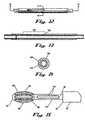
- FIG. 7is a perspective view of an alternative device for delivering and deploying a radially self-expanding stent in accordance with the present invention.
- FIG. 8is a side view of the device for delivering and deploying a radially self-expanding stent in accordance with the present 15 invention
- FIG. 9is a side view of the distal region of a device for delivering and deploying a radially self-expanding stent in accordance with the present invention.
- FIG. 10depicts an enlarged cross sectional view of portions of the deployment visualization features along lines 10 - 10 of the device of FIG. 9 ;
- FIG. 11shows a frontal view of the visualization features along lines 11 - 11 of FIG. 9 ;
- FIG. 12is a perspective view of a portion of a deployment safety mechanism in accordance with the present invention.
- FIG. 13is a perspective view of the slide cavity of the safety mechanism as shown along lines 13 - 13 of the device of FIG. 12 ;
- FIG. 14is a perspective view of a portion of a deployment safety mechanism as shown along lines 14 - 14 of FIG. 12 ;
- FIG. 15is a perspective view of a portion of a device for delivering and deploying a radially self-expanding stent having optical windows that are staggered in orientation and wherein the distal tip has channels formed on the outer surface thereof to facilitate the ingress and egress of utility tools passed through the outer tubular member;
- FIG. 16is a perspective view of a preferred embodiment of a deployment apparatus showing a variety of optional geometries of the working channels formed between the interior and exterior diameters of the outer tubular member.
- FIG. 17is a sectional view of the deployment apparatus shown in FIG. 15 .
- FIG. 18is a perspective view of a deployment apparatus, as shown in FIG. 15 , further comprising a parallel channel for receiving 15 and extending a guidewire;
- FIG. 19is a cross sectional view of an outer tubular member in accordance with a preferred embodiment of the present invention wherein the outer tubular member defines a plurality of longitudinally extending apertures between the inner and outer surfaces thereof forming utility channels;
- FIG. 20is a frontal view of the distal tip showing apertures complementary to the utility channels shown in FIG. 19 ;
- FIG. 21is a side view of a preferred embodiment of a device for delivering and deploying a radially self-expanding stent featuring an alternative distal tip, as shown in FIG. 20 and visualization windows;
- FIG. 22is a perspective view of a preferred embodiment of a delivery and deployment device in accordance with the present invention, wherein the distal tip has utility grooves and the outer tubular member has a substantially beveled distal region for receiving the proximal end of the distal tip.
- a general problem in the diagnosis and therapy of pulmonary defects, bronchial defects, tracheal defects and many other nonvascular anomaliesis the fact that the instruments must be inserted from the mouth or the nose into the larynx or the trachea, wherein it is necessary to pass the area of maximum diameter of about 15 mm. As a result, the inserted instruments take away a very large portion of the free lumen. Consequently, in respiratory lumens spontaneous respiration of the patient is impaired. In addition, there is the danger of injuring the patient.
- the present inventionprovides an instrument, which can be inserted gently, ensures a good utilization of the available space and makes it possible to carry out active therapeutic measures, wherein the instrument is to be particularly suitable for the introduction and placement of stents. It is also within the scope of the present invention to provide a device adaptable for placement in a variety of target sites in a patient's anatomy. In other words, devices in accordance with the present invention should in no way be limited to pulmonary delivery devices as such devices are suitable for a broader range of indications.
- a preferred embodiment of the present deployment apparatuscomprises inner and outer tubular members interactively coupled with each other in a manner that one can move rotationally and proximally or distally with respect to the other.
- the tubular membersare preferably nonpyrogenic.
- the deployment apparatuscomprises a distal tip and a stent-retaining hub, between which the stent is placed.
- the distal tip and the stent-retaining hubare both functionally coupled with the inner tubular member.
- the inner tubular memberterminates with the proximal handpiece.
- the proximal handpieceis preferably a female threaded proximal handpiece, but alternative termini are within the skill of the stent deployment device engineer.
- a suitable alternativewould be a handle having similar internal diameter characteristics as the proximal handpiece while providing greater surface area for manipulating the deployment apparatus.
- the deployment apparatusis preferably sterilized by a validated sterilization cycle EtO.
- the deviceis capable of resterilization (validated cycle) with no degradation of performance.
- the total length of the deployment apparatusvaries based on the location of the target lumen.
- the usable length of the inner tubular membershall be from the inner tubular member distal hub/handle end to the distal tip.
- the usable length of the outer tubular membershall be from the distal hub/handle end of the outer tubular member to the distal tip.
- the overall length of the deviceshall be from the distal hub/handle end of the outer tubular member to the distal tip of the inner tubular member when assembled and not deployed.
- the outer tubular memberis preferably manufactured of stiffer synthetic material. In a preferred embodiment, the length of the outer tubular member is preferably shorter than that of the inner tubular member.
- the outer tubular membermay be configured to allow for the coupling of an optical stent along the exterior diameter thereof.
- the interior diameter of the inner tubular membermay be enlarged sufficiently to accommodate the optical scope and additionally the increased crimped stent diameter.
- the smallest diameter that allows for example a bronchoscope to passwill be employed in this alternative embodiment. It should be understood that through hindsight, after exposure to the present specification, one of ordinary skill would be able to adapt the current device to receive an ultra thin optical scope to the internal diameter of the device without undo experimentation and without departing from the spirit of the present objectives.
- an integrated direct visualization systemwherein an optical cable is coupled with a portion of or comprises the hypotube and preferably capable of extending beyond both the distal and proximal ends of the deployment device such that viewing of any segment of the lumen is possible.
- the camera and light sourceare preferably operatively coupled and disposed about the distal region of the apparatus.
- An exemplary deployment apparatus in accordance with the present inventionis durable while affording adequate flexibility to navigate through anatomical lumens without kinking.
- the deployment apparatusis formed of biocompatible synthetics and in a preferred embodiment reinforced with metal structure. This allows for deployment within an accuracy of about ⁇ 3 mm.
- the stentis preferably released with a force lower than 30 Newtons at 37° C.
- the inner tubular memberis composed of a thin elastic synthetic material, such as polyurethane or Teflon®. At its proximal end, the inner tubular member has a standard adaptor or connector. At its distal end, the inner tubular member is equipped with a tip specific for various anatomical lumens.
- the inner tubular member and the outer tubular membercan be displaced relative to each other in longitudinal direction as well as in a radial direction.
- the deployment apparatus in accordance with the present inventioncan be used most advantageously for the placement of stents.
- stentsare available in various embodiments of metal and/or synthetic material. They usually are composed of a fabric of metal wires, which expand by themselves as a result of their natural tension. Stents of a so-called shape memory alloy are also known. These stents have a small radial diameter at a low temperature, while they expand radially when exceeding an upper threshold temperature, so that they can keep a stenosis open in this manner. It is particularly advantageous to use stents of an alloy of nickel and titanium, the so-called nitinol.
- An exemplary deployment apparatuscan be used for the placement of various stents, whether they are self-expanding stents or stents, which require activation.
- the stentis placed in the free space between the outer tubular member and the inner tubular member.
- Positioning of the stent in the deployment apparatuscan be carried out in the area between the tip and the stent-retaining hub at the distal end of the inner tubular member.
- fasteners or other suitable retaining elementsmay hold the stent.
- the outer tubular memberwhen the stent is inserted and after the stenosis has been passed, the outer tubular member is retracted, so that the stent is released.
- the distal end of the outer tubular membermay be placed about the stenosis so that the inner ‘tubular member may be extended so that the stent is placed in direct contact with the desired location prior to expansion.
- a self expanding stentthen by itself assumes the expanded position. This eliminates the need for post expansion positioning techniques.
- the devicehas fasteners that retain contact with a portion of the stent in the event that the stent needs to be retracted or repositioned.
- a stent suitable for such procedureswould be one in accordance with the disclosure in co-pending U.S. patent application Ser. No. 10/190,770, which is incorporated herein in its entirety by this reference.
- the present inventionprovides a stent deployment apparatus 10 that includes an outer tubular member 50 and an inner tubular member 30 , wherein the outer tubular member 50 and the inner tubular member 30 can be displaced relative to each other.
- a proximal handpiece 14At the proximal end of an exemplary device 10 is a proximal handpiece 14 , coupled with a portion of the inner tubular member 30 and preferably a portion of a hypotube 16 .
- the hypotube throughout this specificationmay refer to a standard catheter hypotube or alternatively a single or bundle of optical fiber for use in the direct visualization embodiments in accordance with the present invention.
- a suitable alternative terminusmay be employed as long as it provides the minimum benefits provided by a proximal handpiece.
- the hypotube 16is disposed about the inner tube 30 and extends from a location adjacent to the proximal handpiece 14 through a portion of the handle 40 of the deployment apparatus 10 .
- the hypotube 16terminates within the proximal handpiece 14 .
- a safety mechanism 18is provided that is formed in part by the complementary fitting of a portion of the handle 40 and a stop 20 coupled with the hypotube 16 between the proximal handpiece 14 and the handle 40 .
- the stop 20is preferably molded onto the hypotube 16 , the molding process resulting in a tab 24 formed on the stop 20 that is subsequently broken when the physician desires to place the deployment apparatus 10 in the proceed orientation.
- the stop 20may potentially rotate freely about the hypotube 16 .
- a preferred stop 20includes female locking members 22 comprising channels formed along the exterior thereof that are complementary to the male locking members 46 formed on the interior cavity 42 along the proximal region of the handle 40 .
- the male locking members 42 and female locking members 22can be formed into any shape or suitable size as long as they do not depart from the essential purpose of forming a safety mechanism.
- the cavity 42 of the handle 40is designed to receive the stop 20 and prevent further deployment.
- the stop 20is molded at a distance along the hypotube 16 such that the distance between the distal end of the stop 20 and the base 44 of the complementary cavity 42 of the handle 40 roughly corresponds to the critical deployment point.
- the handle 40is preferably molded to a portion of the outer tubular member 50 , which extends from the handle 40 to the distal tip 60 of the device 10 .
- the outer tubular member 50is disposed about the inner tubular member 30 .
- the outer tubular member 50is clear so that the inner tubular member 50 is visible there through.
- markers 80 - 84preferably formed on portions of the inner tubular member 30 are also visible through the outer tubular member 50 .
- the stent-retaining hub 70in the distal region 54 of the device 10 , there is a stent-retaining hub 70 , which holds the stent 71 during the placement procedure.
- the stent-retaining hub 70comprises two double conical shaped elements, one disposed at each end of the stent 71 and coupled with the inner tubular member 30 .
- the distal most double conical shaped elementis the distal tip of the device 60 .
- the stent-retaining hub 70may also comprise proximal 72 and distal 74 stops between which the stent 71 rests in its crimped state.
- the stent-retaining hub 70may be removable so as to allow a pre-sterilized, crimped stent containing, hub 70 to be installed in the distal region of the device for stent delivery and deployment. Moreover, the proximal end of the stent 71 may also be restrained by conventional coupling methods (not shown) to facilitate retrieval if necessary. By way of example, which is in no way to be construed as limiting, a stent having suture disposed about its proximal end may be retained by the stent-retaining hub 70 that has releasable finger-like members engaging the suture.
- the deviceis configured such that an optional guidewire 12 may be passed through the internal diameter 32 of the device through the proximal handpiece 14 at the proximal end, the distal tip 60 at the distal end and the inner tubular member 30 there between.
- the internal diameter 32 of the device 10is sufficient to receive an optical scope there through.
- the optical scopemay pass about the guidewire 12 from the proximal to and through the distal ends of the deployment apparatus 10 . This is so as to allow the physician to view a patient's anatomy that may lie distal of the distal tip 60 of the deployment apparatus 10 .
- a single fiberscopemay be provided that is coupled with the guidewire.
- outer tubular member 50 and the inner tubular member 30may be adapted so that instead of feeding the optical scope through the proximal handpiece 14 , the mating apertures are formed along a portion of the longitudinal expanse of the inner tubular member 30 and an entry point formed on a portion of the outer tubular member so as to receive the scope through both the inner tubular member 30 and the outer tubular member 50 even as the inner tubular member 30 and outer tubular member 50 are moved rotationally and proximally or distally with respect to the other.
- a deployment deviceis provided that has a distal tip 60 having a light source 160 , lens 170 and working channel 32 operatively configured therein to allow direct visualization of the target site.
- the present inventionin alternative embodiments shown in FIGS. 18-19 , provides deployment devices wherein guidewires 12 ; optical instruments 120 and other therapeutic tools may be provided through alternative means.
- a guidewire receiving member(not shown) and an optical instrument receiving member (not shown) are provided that allows one or both of these devices to travel to the distal tip 60 of the device 10 via the internal diameter 32 of the inner tubular member 30 .
- an optical instrument 120is coupled with a portion of inner tubular member 30 and extends beyond both the distal and proximal ends thereof.
- the optical instrument 120may be configured to have an external light source that is connected by the light source connector 126 .
- a CCD or Lensis connected to the optical instrument 120 by connector 128 .
- the optical deviceallows for the visual display on conventional display means known in the art.
- the device 10may also be configured so that the guidewire 12 and/or the optical instrument 120 can pass between the light source connector 126 and the lens connector 128 , obtaining access to either the inner tubular member 30 or the outer tubular member 50 .
- FIG. 19Yet another and preferred embodiment of a deployment device in accordance with the present invention is the device 10 as shown in FIG. 19 , wherein the outer tubular member 50 defines a plurality of longitudinally extending utility channels 55 between the inner 56 and outer surfaces 52 of the outer tubular member 50 .
- an optical instrument 120 , guidewire 12 , or other medical appliancemay be disposed through these channels to provide therapeutic results.
- the channelsextend longitudinally from the proximal to the distal ends of the outer tubular member 50 and may also themselves define openings (not shown) that allow the preferred medical appliance (e.g., optical instrument, guidewire, etc) to enter the inner tubular member at locations between the distal and proximal ends thereof.
- the openingsmay be formed through both the inner surface 56 of the outer tubular member 50 and potentially both the inner 32 and outer 34 surfaces of the inner tubular member 30 .
- FIGS. 15-16 & 22show a deployment device 10 that has an outer tubular member 50 having a plurality of utility channels 55 for passing instruments and devices, useful during a procedure, through the device 10 to the target location.
- distal tip 60has complementary utility grooves 150 to allow the instruments and devices to pass beyond the distal end of the outer tubular member 50 .
- FIG. 15also shows the advantage of having optical windows 110 in general and staggered optical windows 110 in particular to optimize visualization proximal the distal tip 60 .
- a suitable instrument passed along the utility channels 55 of the outer tubular member 50 and the utility groove 150 of the distal tip 60would be a guidewire 12 , though many other useful instruments may be employed, limited only by the need to keep the exterior diameter 52 of the outer tubular member 50 within a range that can fit in the lumen in which the device 10 will be introduced.
- the guidewirecould be a standard guidewire, or alternatively a specialized ultra thin guidewire having optical capabilities.
- An alternative instrumentis a syringe system (not shown) that can be integrally coupled with the delivery and deployment device 10 or alternatively configured to pass through either the working channel 32 or 56 of the inner 30 or outer 50 tubular members, respectively, or the utility channels 55 of the outer tubular member 50 .
- An exemplary syringe systemmay have thermotherapy, cryotherapy, photodynamic, chemotherapy capabilities or combinations of these capabilities. In either configuration, but particularly the chemotherapeutic embodiment, the syringe system provides an extendable/retractable needle for delivering a therapeutic dose of a bioactive product such as a chemotherapeutic agent.
- the needlemay alternatively be, for example, an electrocautery probe, for certain thermotherapy indications, or the bioactive product may be a suitable photosensitizer, in certain photodynamic therapy indications. Therefore, in order to adapt to the desired capabilities and a variety of indications, the general syringe system may be adapted in accordance with methods known in the art without requiring undue experimentation. It is preferable, in the chemotherapeutic and/or the photodynamic application, however, that the needle be introduced into a target lesion and the bioactive product introduced. It should be noted that the syringe system is useful in both malignant and benign applications.
- the syringe systemcomprises a needle at the distal end and a reservoir of bioactive product proximally situated, with a conduit servicing the needle and reservoir there between.
- the syringe systemis configured to provide for extension and/or retraction of the needle to a target site in both the stand alone and integrated configurations.
- the stand-alone versionis a general reference to the embodiment that is suitable for situating through appropriate channels of the device, but is not coupled thereto.
- an exemplary photodynamic therapy devicewould have essential features of U.S. Pat. No. 6,454,789B1 to Chen et al., which is incorporated in its entirety by this reference; an exemplary thermotherapy device would have essential features of U.S. Pat. No. 6,488,697 to Ariura et al., which is incorporated in its entirety by this reference; an exemplary cryotherapy device would have essential features of U.S. Pat. No. 6,514,245B1 to Williams et al., which is incorporated in its entirety by this reference; and an exemplary electrocautery device would have essential features of U.S. Pat. No.
- the syringe systemmay alternatively be configured for sealing a bleb, serving as a vehicle for drug administration or air removal from a bleb, etc. Therefore, it would be within the capacity of one of ordinary skill in the relevant medical device art to adapt such utility instruments for use with or as an integrated component of the present invention without undue experimentation.
- the bioactive productmay be a variety of therapeutic substances, but for chemotherapeutic indications, it may comprise a wide variety of chemotherapeutic agents such as but not limited to the exemplary chemotherapeutic agents like cis-platinum, paclitaxol, 5-fluorouracil, gemcytobine and navelbine.
- the chemotherapeutic agentsare generally grouped as DNA-interactive Agents, Antimetabolites, Tubulin-Interactive Agents, Hormonal agents and others such as Asparaginase or Hydroxyurea. Each of the groups of chemotherapeutic agents can be further divided by type of activity or compound.
- chemotherapeutic agents used in combination with the anti-cancer agents or benzimidazoles of this inventioninclude members of all of these groups.
- chemotherapeutic agents and their method of administrationsee Dorr, et al, Cancer Chemotherapy Handbook, 2 d edition , pages 15-34, Appleton & Lange (Connecticut, 1994) herein incorporated by this reference.
- DNA-Interactive Agentsinclude the alkylating agents, e.g. Cisplatin, Cyclophosphamide, Altretamine; the DNA strand-breakage agents, such as Bleomycin; the intercalating topoisomerase II inhibitors, e.g., Dactinomycin and Doxorubicin); the nonintercalating topoisomerase II inhibitors such as, Etoposide and Teniposide; and the DNA minor groove binder Plicamycin.
- the alkylating agentsform covalent chemical adducts with cellular DNA, RNA, and protein molecules and with smaller amino acids, glutathione and similar chemicals.
- these alkylating agentsreact with a nucleophilic atom in a cellular constituent, such as an amino, carboxyl, phosphate, or sulfhydryl group in nucleic acids, proteins, amino acids, or glutathione.
- a nucleophilic atomsuch as an amino, carboxyl, phosphate, or sulfhydryl group in nucleic acids, proteins, amino acids, or glutathione.
- Typical alkylating agentsinclude: Nitrogen mustards, such as Chlorambucil, Cyclophosphamide, Isofamide, Mechlorethamine, Melphalan, Uracil mustard; aziridines such as Thiotepa; methanesulfonate esters such as Busulfan; nitroso ureas, such as Cannustine, Lomustine, Streptozocin; platinum complexes, such as Cisplatin, Carboplatin; bioreductive alkylator, such as Mitomycin, and Procarbazine, dacarbazine and Altretamine; DNA strand breaking agents include Bleomycin; DNA topoisomerase II inhibitors include the following: Intercalators, such as Amsacrine, Dactinomycin, Daunorubicin, Doxorubicin, Idarubicin, and Mitoxantrone; nonintercalators, such as Etoposide and Teniposide.
- the DNA minor groove binderis Plica
- the Antimetabolitesinterfere with the production of nucleic acids by one or the other of two major mechanisms. Some of the drugs inhibit production of the deoxyribonucleoside triphosphates that are the immediate precursors for DNA synthesis, thus inhibiting DNA replication. Some of the compounds are sufficiently like purines or pyrimidines to be able to substitute for them in the anabolic nucleotide pathways. These analogs can then be substituted into the DNA and RNA instead of their normal counterparts.
- the Antimetabolites useful hereininclude: folate antagonists such as Methotrexate and trimetrexate pyrimidine antagonists, such as Fluorouracil, Fluorodeoxyuridine, CB3717, Azacytidine, Cytarabine, and Floxuridine purine antagonists include Mercaptopurine, 6-Thioguanine, Fludarabine, Pentostatin; sugar modified analogs include Cyctrabine, Fludarabine; ribonucleotide reductase inhibitors include Hydroxyurea.
- folate antagonistssuch as Methotrexate and trimetrexate pyrimidine antagonists, such as Fluorouracil, Fluorodeoxyuridine, CB3717, Azacytidine, Cytarabine, and Floxuridine purine antagonists include Mercaptopurine, 6-Thioguanine, Fludarabine, Pentostatin
- sugar modified analogsinclude Cyctrabine, Fludarabine
- Tubulin Interactive agentsact by binding to specific sites on Tubulin, a protein that polymerizes to form cellular microtubules. Microtubules are critical cell structure units. When the interactive agents bind on the protein, the cell cannot form microtubules Tubulin Interactive agents include Vincristine and Vinblastine, both alkaloids and Paclitaxel.
- Hormonal agentsare also useful in the treatment of cancers and tumors. They are used in hormonally susceptible tumors and are usually derived from natural sources. These include: estrogens, conjugated estrogens and Ethinyl Estradiol and Diethylstilbestrol, Chlorotrianisene and Idenestrol; progestins such as Hydroxyprogesterone caproate, Medroxyprogesterone, and Megestrol; androgens such as testosterone, testosterone propionate; fluoxymesterone, methyltestosterone; Adrenal corticosteroids are derived from natural adrenal cortisol or hydrocortisone. They are used because of their anti-inflammatory benefits as well as the ability of some to inhibit mitotic divisions and to halt DNA synthesis. These compounds include Prednisone, Dexamethasone, Methylprednisolone, and Prednisolone.
- Leutinizing hormone releasing hormone agents or gonadotropin-releasing hormone antagonistsare used primarily the treatment of prostate cancer. These include leuprolide acetate and goserelin acetate. They prevent the biosynthesis of steroids in the testes.
- Antihormonal antigensinclude antiestrogenic agents such as Tamosifen, antiandrogen agents such as Flutamide; and antiadrenal agents such as Mitotane and Aminoglutethimide. Hydroxyurea appears to act primarily through inhibition of the enzyme ribonucleotide reductase. Asparaginase is an enzyme that converts asparagine to nonfunctional aspartic acid and thus blocks protein synthesis in the tumor. It should also be noted that the bioactive product may include as much as about 99.9% chemotherapeutic agent to as little as ⁇ 1% chemotherapeutic agent or any amount there between.
- the distal region 54 of outer tubular member 50may be beveled to allow a portion 66 of distal tip 60 to be covered by a portion of outer tubular member 50 without obstructing either the utility channels 55 of the outer tubular member 50 or the utility grooves 150 on the distal tip 60 .
- the distal tip 60may be beveled to receive the distal most portion of the outer tubular member 50 .
- FIG. 19-21shows an alternative embodiment of device 10 wherein the distal tip 60 has a substantially flat proximal face that can abut the distal face of the outer tubular member 50 . Additionally, in either the closed (abutted) or open configurations, instruments can freely pass through the utility channels 55 of the outer tubular member 50 and the utility channels 152 , which are formed through distal tip 60 to complement the utility channels 55 of the outer tubular member 50 .
- one or more of the utility channels 55 and 152themselves may be optical fibers or bundles of optical fibers allowing for direct visualization distal, proximal and through the delivery and deployment device 10 .
- the utility grooves 150may also have internally and/or externally facing optical components.
- the inner surfaces 32 and 56 of the inner 30 and outer 50 tubular members (working channels)may themselves comprise optical characteristics and/or be formed of optical material. Therefore, reference throughout, including in the appended claims, to optical capabilities in the these components refers to either inherit capacity of the component material or capacity provided by adaptively introduced optical components or both.
- FIG. 1a deployment apparatus 10 that includes an elongate and flexible outer tubular member 50 constructed of at least one biocompatible thermoplastic elastomer, e.g. such as polyurethane and nylon, typically with an outside diameter 52 in the range of about between 6-9 mm.
- a central lumen 56runs the length of the outer tubular member 50 .
- a distal region 54 of the outer tubular member 50surrounds the stent to be placed (not shown), and maintains the stent in a crimped delivery configuration, against an elastic restoring force of the stent.
- the stentwhen in a normal unrestrained configuration, generally has a diameter (for example, 10-20 mm) substantially larger than the interior diameter 32 of the inner tubular member 30 .
- the expanded stentis larger in diameter than the body lumen in which the stent is fixed, and the restoring force tends to maintain the stent against the tissue wall.
- Outer tubular member 50is mounted at its proximal end to a handle 40 .
- Outer tubular member 50can be pushed and pulled relative to inner tubular member 30 by hand manipulation of the handle 40 at the proximal end of the outer tubular member 30 and holding the proximal end of the handle 40 .
- a guidewire 12is preferably disposed within the interior lumen 32 of an elongate and flexible inner tubular member 30 , which can be constructed of materials similar to those employed to form the outer tubular member 50 . However, it is preferable that inner tubular member 30 is formed from a more durable material and additionally no guidewire may be necessary.
- a distal tip 60is coupled with inner tubular member 30 about the distal end thereof. Also attached to the inner tubular member 30 are a proximal marker 80 , at least one medial marker 82 and a distal marker 84 .
- the markersare constructed of a radiopaque material, e.g. platinum iridium, and surround the inner tubular member 30 .
- Markers 80 , 82 and 84are axially spaced apart to mark the length of the stent and to mark the critical deployment distance for that stent length.
- the markersidentify a stent-retaining hub 70 of the inner tubular member 30 , more particularly the distal region of the inner tubular member 30 is surrounded by stent 12 .
- Markers 80 and 84have Exterior Diameters slightly smaller than the interior diameter of outer tubular member 50 .
- the outer tubular member 50thus functions as a carrier for the stent, with inner tubular member 30 providing a retaining means for radially compressing the stent and maintaining the stent along the stent-retaining hub 70 , so long as the outer tubular member 50 surrounds the stent.
- the markersmay be more or fewer in number and may also be formed about the interior diameter 32 of the inner tubular member 30 or alternatively, about the interior diameter 56 or exterior diameter 58 of the outer tubular member 50 .
- Inner tubular member 30along its entire length, has an interior lumen 32 open to both the proximal and distal ends of the inner tubular member 30 .
- An axial passage 68 through distal tip 60continues lumen 32 to allow the guidewire 12 to pass from the proximal hand piece 14 through the distal tip 60 .
- Handle 40 and outer tubular member 50are movable relative to inner tubular member 30 . More particularly, the handle 40 is moved proximally relative to the stent-retaining hub 70 , facilitating the movement of outer tubular member 50 relative to inner tubular member 30 so as to provide a means for controllably withdrawing the outer tubular member 50 , relative to the inner tubular member 30 , resulting in the release of the stent for radial self-expansion.
- the initial stepis to position guidewire 12 within the anatomy of a patient. This can be accomplished with a guide cannula (not illustrated), leaving guidewire 12 in place, with the exchange portion of the guidewire extended proximally beyond the point of entry into the anatomy of the patient. Deployment apparatus 10 is then advanced over the guidewire 12 at the exchange portion, with the guidewire 12 being received into passage 68 of distal tip 60 . As device 10 is inserted into the body, the proximal portion of guidewire 12 travels proximally (relative to the device) to the proximal end of guidewire lumen 32 .
- the physicianmaintains guidewire 12 and inner tubular member 30 substantially fixed with one hand, while moving handle 40 in the proximal direction with the other hand, thus to move outer tubular member 50 proximally relative to inner tubular member 30 .
- the stent 71remains substantially fixed relative to inner tubular member 30 , and thus radially self-expands.
- the handle 40encounters the safety mechanism 18 for the critical deployment point (see FIG. 4C ).
- the inner tubular member 30via the handle 40 , may have to be rotated to align and insert the stop 20 into the handle 40 . When fully inserted, further deployment cannot occur without twisting and snapping the stop the tab 24 portion of the stop 20 . Continued retraction of the outer tubular member 50 results in complete deployment of the stent 71 .
- the stentAfter deployment, the stent ideally radially self-expands to a diameter greater than the diameter of outer tubular member 50 . Accordingly, device 10 can be withdrawn proximally through the stent. However, in the event that the stent does not radially expand fully, distal tip 60 is configured to facilitate removal of deployment apparatus 10 through the lumen of the stent.
- Guidewire 12can be withdrawn as well.
- the guidewire 12emerges from the proximal end of the proximal handpiece 14 .
- the deployment apparatus 10can be removed without removing the guidewire 12 .
- Device 10is removed by progressively pulling the device away from the guidewire 12 (which removes the guidewire from within the inner tubular member 30 ), all while maintaining guidewire 12 in place.
- distal tip 60can have a variety of confirmations, but by way of non-limiting example, distal tip 60 comprises first 62 and second 66 ends having a smaller diameter than the medial region 64 thereof.
- each endis conical in shape so as to allow the tip 60 to wedge through an incompletely expanded stent when pulled proximally with respect to the stent.
- the dual conical end designfacilitates removal but sufficiently prevents the crimped stent from releasing from the stent-retaining hub 70 and prematurely expanding.
- Distal tip 60may alternatively have a flared medial region 64 so as to facilitate retrieval and retraction of a misaligned stent 12 .
- the device 10has a deployment safety mechanism 18 that comprises male 46 and female 22 locking members that are brought into functional engagement as the stent is being deployed. Once the stent has reached the critical deployment point, the distal end of the stop 20 is substantially flush with the base 44 of the handle cavity 42 and the female locking members 22 of the stop 20 are in operative communication with the corresponding male locking members 46 formed on the interior surface of the cavity 42 of the handle.
- the safety mechanism 18is engaged as described above, the stent cannot be deployed further without physician intervention. In order to deploy the stent beyond this point, the physician has to rotate the stop 20 to cause the tab 24 to break. Once the tab 24 is broken, the device 10 is in the proceed orientation and deployment may proceed.
- This safety mechanismis in contrast to locks that merely serve as a stabilizer to prevent movement of the tubes during a procedure.
- the physicianwill feel a tactile indication that the device 10 can be deployed further.
- the breaking of the tabmay also, or as a substitute to tactile indication, results in an audible indication that further deployment is possible.
- the physicianis apprised of the fact that deployment beyond this point is irreversible except for interventional retrieval methods.
- the critical deployment pointis preferably about 60% deployment, beyond which retraction is not recommended.
- the safety mechanism 18removes the need to estimate extent of deployment and provides a reliable means of accurately deploying stents.
- Alternative locking mechanismsmay be provided as long as they retain the important characteristic of giving the physician a sensory indication of extent of stent deployment and removes the need to estimate extent of deployment.
- the locking mechanismcould comprise a breakable seal, tab/stop lock, diverted channel safety mechanism, etc.
- a diverted channel safety mechanismis provided generally as 118 .
- a detent 90is coupled with the hypotube 16 .
- the handle 40defines a substantially Z shaped channel 43 that is essentially a continuation of the cavity 43 .
- the shape of the channel 43may vary from an L, S, T or other suitable shape for encouraging user intervention.
- physician interventioncomprises the step of rotating the hypotube 16 such that the detent 90 no longer abuts the base 44 of the handle cavity 42 , rather once rotated, the detent 90 is disposed within the channel 43 of the handle 40 allowing free stent deployment.
- this safety mechanism 118it is preferable that the point of detent/base interaction is about approximately the critical deployment point.
- deploymentis limited to a point where the stent and the device are still retractable absent additional user intervention. Beyond this point, the user understands that deployment may not be easily aborted and reversed.
- the inner tubular member 30defines at least one aperture there through to facilitate viewing with an optical instrument.
- the aperture(s) generally referred to as optical window 110are preferably beveled, as shown in FIG. 11 , to maximize the viewing area available to the optical scope.
- the optical windows 110may be offset or staggered so that at different deployment depths, there is an available optical window 110 .
- these optical windows 110are preferably oval, but may be any number of geometrical shapes such as a polygon, spherical, etc.
- FIGS. 12-14show a preferred safety mechanism.
- the principal featureis the requirement of user intervention in order to fully deploy the stent. This insures that stents are not prematurely deployed.
- all of the alternative embodiments of the present inventionmay be provided with varying dimensions depending on the interventional necessity. For example, as discussed above, the device 10 may have longer or shorter overall dimensions depending on the deployment protocol.
- certain embodiments of the present inventionprovide for the deployment of specialized stents to treat one of the most common causes of spontaneous non-traumatic pneumothorax, namely, a pulmonary bleb.
- stents specifically designed to treat a pulmonary blebmay be delivered via the present delivery device.
- the dimensions and spacing of the stent-retaining hub 70are modified to accommodate the different shape of the stent.
- the stenthas a substantially thimble shape and preferably a self-healing semi-permeable membrane cover, the device 10 does not have the double conical shaped distal tip 60 .
- radial pressure exerted by the bleb stent against the interior surface 56 of the outer tubular member 50provides, sufficient resistance to keep the stent in place prior to deployment.
- the outer tubular member 50can be retracted to fully deploy the stent.
Landscapes
- Health & Medical Sciences (AREA)
- Engineering & Computer Science (AREA)
- Biomedical Technology (AREA)
- Cardiology (AREA)
- Oral & Maxillofacial Surgery (AREA)
- Transplantation (AREA)
- Heart & Thoracic Surgery (AREA)
- Vascular Medicine (AREA)
- Life Sciences & Earth Sciences (AREA)
- Animal Behavior & Ethology (AREA)
- General Health & Medical Sciences (AREA)
- Public Health (AREA)
- Veterinary Medicine (AREA)
- Media Introduction/Drainage Providing Device (AREA)
- Infusion, Injection, And Reservoir Apparatuses (AREA)
- Ultra Sonic Daignosis Equipment (AREA)
- Laser Surgery Devices (AREA)
- Prostheses (AREA)
- Sampling And Sample Adjustment (AREA)
Abstract
Description
- 10 Stent Delivery & Deployment Device
- 12 Guidewire
- 14 Proximal Handpiece
- 16 Hypotube
- 18 Safety Mechanism
- 20 Stop
- 22 Female Locking Member on the Stop
- 24 Tab of the Stop
- 30 Inner Tubular Member
- 32 Interior Diameter of Inner Tubular Member (Working Channel)
- 34 Exterior Diameter of Inner Tubular Member
- 40 Handle
- 42 Cavity in Proximal Portion of Handle
- 43 Inner Channel of Handle
- 44 Base of Handle Cavity
- 46 Male Locking Member
- 48 Inner Handle Hub
- 49 Outer Handle Hub
- 50 Outer Tubular Member
- 52 Exterior Diameter of Outer Tubular Member
- 54 Distal Region of Outer Tubular Member
- 55 Utility Channels of Outer Tubular Member
- 56 Interior Diameter of Outer Tubular Member
- 58 Exterior Tubular Member Utility Channel
- 60 Distal Tip
- 62 First End of the Tip
- 64 Medial Region of the Tip
- 66 Second End of the Tip
- 68 Axial Passage
- 70 Retaining Hub
- 71 Stent
- 72 Distal Region of Retaining Hub
- 74 Proximal Hub of Retaining Hub
- 76 Pusher
- 80 Proximal Marker
- 82 Medial Marker
- 84 Distal Marker
- 90 Detent on Hypotube
- 100 Stent
- 110 Beveled Optical Window
- 118 Channel Safety Mechanism
- 120 Optical Instrument
- 122 Optical Instrument Proximal Region
- 124 Optical Instrument Distal Region
- 126 Optical Instrument Light Source Connection
- 128 Optical Instrument Lens Connector
- 130 Guidewire Receiving Member
- 140 Outer Tube
- 142 Safety Track
- 144 Safety Catch
- 150 Utility Grooves of Distal Tip
- 152 Utility Channels of Distal Tip
- 160 Light Source
- 170 Lens
- 180 Camera
It should also be pointed out at the outset that various embodiments of stent delivery and deployment devices in accordance with the present invention make reference to guidewires and/or optical instruments. In some embodiments the terms may overlap since it is contemplated within the scope of such embodiments that the guidewire itself has visualization capabilities resulting from the guidewire being an ultra thin optical and/or ultrasound device. It should also be evident from the following disclosure that independent placement of traditional and visualization capable guidewires as well as guidewires integrally coupled with the device for placement and deployment of a stent is contemplated and should be considered as residing within the scope of the claims.
Claims (26)
Priority Applications (1)
| Application Number | Priority Date | Filing Date | Title |
|---|---|---|---|
| US12/617,165US8298277B2 (en) | 2003-03-31 | 2009-11-12 | Medical appliance optical delivery and deployment apparatus and method |
Applications Claiming Priority (2)
| Application Number | Priority Date | Filing Date | Title |
|---|---|---|---|
| US10/404,197US7637934B2 (en) | 2003-03-31 | 2003-03-31 | Medical appliance optical delivery and deployment apparatus and method |
| US12/617,165US8298277B2 (en) | 2003-03-31 | 2009-11-12 | Medical appliance optical delivery and deployment apparatus and method |
Related Parent Applications (1)
| Application Number | Title | Priority Date | Filing Date |
|---|---|---|---|
| US10/404,197DivisionUS7637934B2 (en) | 2003-03-31 | 2003-03-31 | Medical appliance optical delivery and deployment apparatus and method |
Publications (2)
| Publication Number | Publication Date |
|---|---|
| US20100057183A1 US20100057183A1 (en) | 2010-03-04 |
| US8298277B2true US8298277B2 (en) | 2012-10-30 |
Family
ID=32990111
Family Applications (2)
| Application Number | Title | Priority Date | Filing Date |
|---|---|---|---|
| US10/404,197Expired - LifetimeUS7637934B2 (en) | 2003-03-31 | 2003-03-31 | Medical appliance optical delivery and deployment apparatus and method |
| US12/617,165Expired - Fee RelatedUS8298277B2 (en) | 2003-03-31 | 2009-11-12 | Medical appliance optical delivery and deployment apparatus and method |
Family Applications Before (1)
| Application Number | Title | Priority Date | Filing Date |
|---|---|---|---|
| US10/404,197Expired - LifetimeUS7637934B2 (en) | 2003-03-31 | 2003-03-31 | Medical appliance optical delivery and deployment apparatus and method |
Country Status (8)
| Country | Link |
|---|---|
| US (2) | US7637934B2 (en) |
| EP (1) | EP1613244B1 (en) |
| JP (2) | JP4668174B2 (en) |
| AT (1) | ATE475382T1 (en) |
| AU (1) | AU2004229342A1 (en) |
| CA (1) | CA2521101A1 (en) |
| DE (1) | DE602004028351D1 (en) |
| WO (1) | WO2004091452A1 (en) |
Cited By (8)
| Publication number | Priority date | Publication date | Assignee | Title |
|---|---|---|---|---|
| US20120041534A1 (en)* | 2010-08-10 | 2012-02-16 | Boston Scientific Scimed, Inc. | Stent delivery system with integrated camera |
| US9700401B2 (en) | 2013-09-12 | 2017-07-11 | Boston Scientific Scimed, Inc. | Stent with anti-migration connectors |
| US10117763B2 (en) | 2014-03-18 | 2018-11-06 | Boston Scientific Scimed, Inc. | Reduced granulation and inflammation stent design |
| US10130498B2 (en) | 2014-10-22 | 2018-11-20 | Boston Scientific Scimed, Inc. | Stent with flexible hinge |
| US10219921B2 (en) | 2014-10-02 | 2019-03-05 | Boston Scientific Scimed, Inc. | Controlled ingrowth feature for antimigration |
| US10898354B2 (en) | 2014-11-06 | 2021-01-26 | Boston Scientific Scimed, Inc. | Tracheal stent |
| US11484423B2 (en) | 2018-08-21 | 2022-11-01 | Cook Medical Technologies Llc | Apparatuses to facilitate prosthesis placement |
| US11759341B2 (en) | 2020-01-13 | 2023-09-19 | Boston Scientific Scimed, Inc. | Anti-migration stent |
Families Citing this family (116)
| Publication number | Priority date | Publication date | Assignee | Title |
|---|---|---|---|---|
| US7018401B1 (en) | 1999-02-01 | 2006-03-28 | Board Of Regents, The University Of Texas System | Woven intravascular devices and methods for making the same and apparatus for delivery of the same |
| DK1401352T3 (en) | 2001-06-14 | 2012-06-25 | Kenton W Gregory | PROCEDURE FOR PREPARING A CHITOSANOUS COMPOUND |
| US8741335B2 (en) | 2002-06-14 | 2014-06-03 | Hemcon Medical Technologies, Inc. | Hemostatic compositions, assemblies, systems, and methods employing particulate hemostatic agents formed from hydrophilic polymer foam such as Chitosan |
| US7371403B2 (en)* | 2002-06-14 | 2008-05-13 | Providence Health System-Oregon | Wound dressing and method for controlling severe, life-threatening bleeding |
| US20030050648A1 (en) | 2001-09-11 | 2003-03-13 | Spiration, Inc. | Removable lung reduction devices, systems, and methods |
| US6592594B2 (en) | 2001-10-25 | 2003-07-15 | Spiration, Inc. | Bronchial obstruction device deployment system and method |
| US20030216769A1 (en) | 2002-05-17 | 2003-11-20 | Dillard David H. | Removable anchored lung volume reduction devices and methods |
| US20030181922A1 (en) | 2002-03-20 | 2003-09-25 | Spiration, Inc. | Removable anchored lung volume reduction devices and methods |
| US20050137512A1 (en) | 2003-12-23 | 2005-06-23 | Campbell Todd D. | Wound dressing and method for controlling severe, life-threatening bleeding |
| US8269058B2 (en) | 2002-06-14 | 2012-09-18 | Hemcon Medical Technologies, Inc. | Absorbable tissue dressing assemblies, systems, and methods formed from hydrophilic polymer sponge structures such as chitosan |
| US7100616B2 (en) | 2003-04-08 | 2006-09-05 | Spiration, Inc. | Bronchoscopic lung volume reduction method |
| AU2004263171B2 (en) | 2003-08-07 | 2008-12-04 | Merit Medical Systems, Inc. | Therapeutic medical appliance, delivery and method of use |
| US7533671B2 (en) | 2003-08-08 | 2009-05-19 | Spiration, Inc. | Bronchoscopic repair of air leaks in a lung |
| US8292943B2 (en) | 2003-09-03 | 2012-10-23 | Bolton Medical, Inc. | Stent graft with longitudinal support member |
| US7763063B2 (en) | 2003-09-03 | 2010-07-27 | Bolton Medical, Inc. | Self-aligning stent graft delivery system, kit, and method |
| US11259945B2 (en) | 2003-09-03 | 2022-03-01 | Bolton Medical, Inc. | Dual capture device for stent graft delivery system and method for capturing a stent graft |
| US20080264102A1 (en) | 2004-02-23 | 2008-10-30 | Bolton Medical, Inc. | Sheath Capture Device for Stent Graft Delivery System and Method for Operating Same |
| US11596537B2 (en) | 2003-09-03 | 2023-03-07 | Bolton Medical, Inc. | Delivery system and method for self-centering a proximal end of a stent graft |
| EP1701675B1 (en)* | 2004-01-08 | 2010-07-14 | Merit Medical Systems, Inc. | Implantable device delivery system handle and method of use |
| US20050278010A1 (en)* | 2004-05-27 | 2005-12-15 | Scimed Life Systems, Inc. | Stent delivery system with imaging capability |
| AU2005262541B2 (en)* | 2004-06-16 | 2011-04-21 | Cook Incorporated | Thoracic deployment device and stent graft |
| US9204957B2 (en) | 2005-03-17 | 2015-12-08 | Hemcon Medical Technologies, Inc. | Systems and methods for hemorrhage control and or tissue repair |
| EP1895951A1 (en)* | 2005-05-13 | 2008-03-12 | Alveolus Inc. | Delivery device allowing visual inspection of an intravascular site |
| US7731654B2 (en) | 2005-05-13 | 2010-06-08 | Merit Medical Systems, Inc. | Delivery device with viewing window and associated method |
| GB0512320D0 (en)* | 2005-06-16 | 2005-07-27 | Angiomed Ag | Catheter device FLEXX tube |
| GB0512319D0 (en) | 2005-06-16 | 2005-07-27 | Angiomed Ag | Catheter device variable pusher |
| GB0512321D0 (en)* | 2005-06-16 | 2005-07-27 | Angiomed Ag | Catheter device double swaging |
| EP1907042B1 (en) | 2005-07-06 | 2009-03-11 | Vascular Pathways Inc. | Intravenous catheter insertion device and method of use |
| US7691151B2 (en) | 2006-03-31 | 2010-04-06 | Spiration, Inc. | Articulable Anchor |
| US8535368B2 (en) | 2006-05-19 | 2013-09-17 | Boston Scientific Scimed, Inc. | Apparatus for loading and delivering a stent |
| JP2009538192A (en)* | 2006-05-23 | 2009-11-05 | プロビデンス ヘルス システム−オレゴン ディー/ビー/エー プロビデンス セント ビンセント メディカル センター | System and method for introducing and applying a bandage structure within a body lumen or body hollow organ |
| JP4910566B2 (en)* | 2006-08-22 | 2012-04-04 | 日本ゼオン株式会社 | Stent delivery catheter |
| US20080051867A1 (en)* | 2006-08-28 | 2008-02-28 | Davila Luis A | Multiple in vivo implant delivery device |
| US7931647B2 (en) | 2006-10-20 | 2011-04-26 | Asthmatx, Inc. | Method of delivering energy to a lung airway using markers |
| MX2009004291A (en) | 2006-10-22 | 2009-09-07 | Idev Technologies Inc | Methods for securing strand ends and the resulting devices. |
| KR101659197B1 (en) | 2006-10-22 | 2016-09-22 | 이데브 테크놀로지스, 아이엔씨. | Devices and methods for stent advancement |
| EP2659861B1 (en) | 2007-05-15 | 2019-03-13 | JenaValve Technology, Inc. | Handle for manipulating a catheter tip, catheter system and medical insertion system for inserting a self-expandable heart valve stent |
| US8235983B2 (en) | 2007-07-12 | 2012-08-07 | Asthmatx, Inc. | Systems and methods for delivering energy to passageways in a patient |
| US9044266B2 (en)* | 2007-09-19 | 2015-06-02 | Cook Medical Technologies Llc | Implant deployment device |
| US8043301B2 (en) | 2007-10-12 | 2011-10-25 | Spiration, Inc. | Valve loader method, system, and apparatus |
| EP2641572B1 (en)* | 2007-10-12 | 2019-07-24 | Spiration Inc. | Valve loader method, system, and apparatus |
| US20090112252A1 (en)* | 2007-10-27 | 2009-04-30 | Salviac Limited | Catheter with removable filter retrieval tip |
| US8858609B2 (en)* | 2008-02-07 | 2014-10-14 | Intuitive Surgical Operations, Inc. | Stent delivery under direct visualization |
| AU2009241687A1 (en) | 2008-05-02 | 2009-11-05 | Providence Health System-Oregon D/B/A Providence St. Vincent Medical Center | Wound dressing devices and methods |
| CN102076281B (en)* | 2008-06-30 | 2014-11-05 | 波顿医疗公司 | Systems and methods for abdominal aortic aneurysm |
| EP2313032B1 (en)* | 2008-08-19 | 2020-12-23 | Merit Medical Systems, Inc. | Delivery device with a protective member |
| US8597454B2 (en)* | 2008-09-23 | 2013-12-03 | Cook Medical Technologies Llc | Catheter tip assembly |
| EP2340002B1 (en) | 2008-10-06 | 2015-03-25 | Providence Health System - Oregon | Foam medical devices and methods |
| GB0822106D0 (en)* | 2008-12-03 | 2009-01-07 | Angiomed Ag | Retractable catheter |
| EP3284447B1 (en) | 2009-03-13 | 2020-05-20 | Bolton Medical Inc. | System for deploying an endoluminal prosthesis at a surgical site |
| JP5284165B2 (en)* | 2009-03-31 | 2013-09-11 | テルモ株式会社 | Biological organ lesion improvement device |
| US8926693B2 (en) | 2010-02-17 | 2015-01-06 | Medtronic, Inc. | Heart valve delivery catheter with safety button |
| US9872971B2 (en) | 2010-05-14 | 2018-01-23 | C. R. Bard, Inc. | Guidewire extension system for a catheter placement device |
| US9950139B2 (en) | 2010-05-14 | 2018-04-24 | C. R. Bard, Inc. | Catheter placement device including guidewire and catheter control elements |
| US10384039B2 (en) | 2010-05-14 | 2019-08-20 | C. R. Bard, Inc. | Catheter insertion device including top-mounted advancement components |
| US11925779B2 (en) | 2010-05-14 | 2024-03-12 | C. R. Bard, Inc. | Catheter insertion device including top-mounted advancement components |
| US9023095B2 (en) | 2010-05-27 | 2015-05-05 | Idev Technologies, Inc. | Stent delivery system with pusher assembly |
| BR112013003610A2 (en)* | 2010-08-17 | 2016-08-16 | St Jude Medical | placement system for placing and implanting a medical implant |
| US8784468B2 (en) | 2010-11-17 | 2014-07-22 | Boston Scientific Scimed, Inc. | Stent delivery systems and locking members for use with stent delivery systems |
| EP2648654B1 (en) | 2010-12-07 | 2024-02-14 | Merit Medical Systems, Inc. | Stent delivery systems |
| WO2012088089A1 (en)* | 2010-12-22 | 2012-06-28 | Boston Scientific Scimed, Inc. | Stent deployment system with integrated digital camera and dilation balloon |
| US8690833B2 (en) | 2011-01-31 | 2014-04-08 | Vascular Pathways, Inc. | Intravenous catheter and insertion device with reduced blood spatter |
| ES2835652T3 (en) | 2011-02-25 | 2021-06-22 | Bard Inc C R | Medical component insertion device including a retractable needle |
| US8795241B2 (en) | 2011-05-13 | 2014-08-05 | Spiration, Inc. | Deployment catheter |
| US9192496B2 (en) | 2011-10-31 | 2015-11-24 | Merit Medical Systems, Inc. | Systems and methods for sheathing an implantable device |
| US9072624B2 (en) | 2012-02-23 | 2015-07-07 | Covidien Lp | Luminal stenting |
| US9271855B2 (en) | 2012-05-09 | 2016-03-01 | Abbott Cardiovascular Systems Inc. | Catheter having hydraulic actuator with tandem chambers |
| US20130304180A1 (en) | 2012-05-09 | 2013-11-14 | Michael L. Green | Catheter having dual balloon hydraulic actuator |
| US9011513B2 (en) | 2012-05-09 | 2015-04-21 | Abbott Cardiovascular Systems Inc. | Catheter having hydraulic actuator |
| US10420662B2 (en) | 2013-03-12 | 2019-09-24 | Abbott Cardiovascular Systems Inc. | Catheter having movable tubular structure and proximal stopper |
| US9326875B2 (en) | 2013-03-13 | 2016-05-03 | Abbott Cardiovascular Systems Inc. | Catheter having a movable tubular structure and method of making |
| EP2967950A1 (en)* | 2013-03-12 | 2016-01-20 | Abbott Cardiovascular Systems Inc. | Catheter having movable tubular structure and proximal stopper |
| US9283101B2 (en) | 2013-03-12 | 2016-03-15 | Abbott Cardiovascular Systems Inc. | Catheter having hydraulic actuator and locking system |
| US10531971B2 (en) | 2013-03-12 | 2020-01-14 | Abbott Cardiovascular System Inc. | Balloon catheter having hydraulic actuator |
| US9439751B2 (en) | 2013-03-15 | 2016-09-13 | Bolton Medical, Inc. | Hemostasis valve and delivery systems |
| US9814618B2 (en) | 2013-06-06 | 2017-11-14 | Boston Scientific Scimed, Inc. | Devices for delivering energy and related methods of use |
| US10045867B2 (en) | 2013-08-27 | 2018-08-14 | Covidien Lp | Delivery of medical devices |
| US9782186B2 (en) | 2013-08-27 | 2017-10-10 | Covidien Lp | Vascular intervention system |
| US9414917B2 (en)* | 2013-09-17 | 2016-08-16 | Medtronic, Inc. | Systems and methods for loading a valve prosthesis onto a catheter |
| WO2015057838A1 (en) | 2013-10-15 | 2015-04-23 | Boston Scientific Scimed, Inc. | Methods and systems for loading and delivering a stent |
| CN104127616A (en)* | 2014-08-01 | 2014-11-05 | 孙苗苗 | Traumatic pneumothorax treatment medicine |
| US10195064B2 (en) | 2014-08-15 | 2019-02-05 | W. L. Gore & Associates, Inc. | Endoprosthesis delivery systems with improved retraction |
| WO2016037127A1 (en) | 2014-09-05 | 2016-03-10 | C.R. Bard, Inc. | Catheter insertion device including retractable needle |
| WO2016141295A1 (en) | 2015-03-05 | 2016-09-09 | Merit Medical Systems, Inc. | Vascular prosthesis deployment device and method of use |
| USD903100S1 (en) | 2015-05-01 | 2020-11-24 | C. R. Bard, Inc. | Catheter placement device |
| CN113350614A (en) | 2015-05-15 | 2021-09-07 | C·R·巴德股份有限公司 | Catheter placement device including extendable needle safety feature |
| CN105031115A (en)* | 2015-07-14 | 2015-11-11 | 四川金堂海纳生物医药技术研究所 | Medicinal decoction for treating traumatic pneumothorax and preparation method thereof |
| US10470906B2 (en) | 2015-09-15 | 2019-11-12 | Merit Medical Systems, Inc. | Implantable device delivery system |
| WO2017087675A1 (en) | 2015-11-20 | 2017-05-26 | Cardiac Pacemakers, Inc. | Delivery devices and methods for leadless cardiac devices |
| AU2016355676B2 (en) | 2015-11-20 | 2018-12-13 | Cardiac Pacemakers, Inc. | Delivery devices and methods for leadless cardiac devices |
| DE102016212882A1 (en)* | 2016-07-14 | 2018-01-18 | Siemens Healthcare Gmbh | Method for planning support in interventional intervention and system |
| US10493262B2 (en) | 2016-09-12 | 2019-12-03 | C. R. Bard, Inc. | Blood control for a catheter insertion device |
| CN115054413A (en) | 2016-09-29 | 2022-09-16 | 美国医疗设备有限公司 | Method of adjusting effective length of stent and prosthesis delivery catheter assembly |
| US10376396B2 (en) | 2017-01-19 | 2019-08-13 | Covidien Lp | Coupling units for medical device delivery systems |
| EP3585471B1 (en) | 2017-03-01 | 2025-01-01 | C. R. Bard, Inc. | Catheter insertion device |
| EP4467111A3 (en) | 2017-03-15 | 2025-03-05 | Merit Medical Systems, Inc. | Transluminal stents |
| US11628078B2 (en) | 2017-03-15 | 2023-04-18 | Merit Medical Systems, Inc. | Transluminal delivery devices and related kits and methods |
| USD836194S1 (en) | 2017-03-21 | 2018-12-18 | Merit Medical Systems, Inc. | Stent deployment device |
| US10842448B2 (en)* | 2017-06-30 | 2020-11-24 | Surgentec Llc | Device and method for determining proper screw or implant size during orthopedic surgery |
| ES2980192T3 (en)* | 2018-03-07 | 2024-09-30 | Bard Access Systems Inc | Guidewire advancement and blood reflux systems for a medical device insertion system |
| US11071637B2 (en) | 2018-04-12 | 2021-07-27 | Covidien Lp | Medical device delivery |
| US10786377B2 (en) | 2018-04-12 | 2020-09-29 | Covidien Lp | Medical device delivery |
| US11413176B2 (en) | 2018-04-12 | 2022-08-16 | Covidien Lp | Medical device delivery |
| US11123209B2 (en) | 2018-04-12 | 2021-09-21 | Covidien Lp | Medical device delivery |
| US10441449B1 (en) | 2018-05-30 | 2019-10-15 | Vesper Medical, Inc. | Rotary handle stent delivery system and method |
| USD921884S1 (en) | 2018-07-27 | 2021-06-08 | Bard Access Systems, Inc. | Catheter insertion device |
| US10449073B1 (en) | 2018-09-18 | 2019-10-22 | Vesper Medical, Inc. | Rotary handle stent delivery system and method |
| US11413174B2 (en) | 2019-06-26 | 2022-08-16 | Covidien Lp | Core assembly for medical device delivery systems |
| CA3151126A1 (en) | 2019-08-19 | 2021-02-25 | Becton, Dickinson And Company | Midline catheter placement device |
| US11219541B2 (en) | 2020-05-21 | 2022-01-11 | Vesper Medical, Inc. | Wheel lock for thumbwheel actuated device |
| EP4585192A3 (en) | 2020-06-24 | 2025-10-15 | Bolton Medical, Inc. | Anti-backspin component for vascular prosthesis delivery device |
| EP4185239A4 (en) | 2020-07-24 | 2024-08-07 | Merit Medical Systems, Inc. | ESOPHAGEAL STENT PROSTHESES AND RELATED METHODS |
| CA3194910A1 (en) | 2020-10-26 | 2022-05-05 | Tiffany ETHRIDGE | Esophageal stents with helical thread |
| US12042413B2 (en) | 2021-04-07 | 2024-07-23 | Covidien Lp | Delivery of medical devices |
| US12109137B2 (en) | 2021-07-30 | 2024-10-08 | Covidien Lp | Medical device delivery |
| US11944558B2 (en) | 2021-08-05 | 2024-04-02 | Covidien Lp | Medical device delivery devices, systems, and methods |
Citations (327)
| Publication number | Priority date | Publication date | Assignee | Title |
|---|---|---|---|---|
| US3196876A (en) | 1961-05-10 | 1965-07-27 | Maurice M Miller | Dilator |
| US4343048A (en) | 1979-08-06 | 1982-08-10 | Ross Donald N | Stent for a cardiac valve |
| US4606330A (en) | 1983-08-09 | 1986-08-19 | Richard Wolf Gmbh | Device for disintegrating stones in bodily cavities or ducts |
| US4665906A (en) | 1983-10-14 | 1987-05-19 | Raychem Corporation | Medical devices incorporating sim alloy elements |
| US4680031A (en) | 1982-11-29 | 1987-07-14 | Tascon Medical Technology Corporation | Heart valve prosthesis |
| US4733665A (en) | 1985-11-07 | 1988-03-29 | Expandable Grafts Partnership | Expandable intraluminal graft, and method and apparatus for implanting an expandable intraluminal graft |
| US4820262A (en) | 1985-12-12 | 1989-04-11 | Medical Engineering Corporation | Ureteral stent |
| US4893623A (en) | 1986-12-09 | 1990-01-16 | Advanced Surgical Intervention, Inc. | Method and apparatus for treating hypertrophy of the prostate gland |
| EP0364420A1 (en) | 1988-09-28 | 1990-04-18 | Ams Medinvent S.A. | A device for transluminal implantation or extraction |
| EP0378151A2 (en) | 1989-01-09 | 1990-07-18 | Cordis Corporation | Endovascular stent apparatus and method |
| US5019085A (en) | 1988-10-25 | 1991-05-28 | Cordis Corporation | Apparatus and method for placement of a stent within a subject vessel |
| US5032128A (en) | 1988-07-07 | 1991-07-16 | Medtronic, Inc. | Heart valve prosthesis |
| US5067957A (en) | 1983-10-14 | 1991-11-26 | Raychem Corporation | Method of inserting medical devices incorporating SIM alloy elements |
| US5073694A (en) | 1991-02-21 | 1991-12-17 | Synthes (U.S.A.) | Method and apparatus for laser cutting a hollow metal workpiece |
| US5102417A (en) | 1985-11-07 | 1992-04-07 | Expandable Grafts Partnership | Expandable intraluminal graft, and method and apparatus for implanting an expandable intraluminal graft |
| US5104404A (en) | 1989-10-02 | 1992-04-14 | Medtronic, Inc. | Articulated stent |
| US5159920A (en) | 1990-06-18 | 1992-11-03 | Mentor Corporation | Scope and stent system |
| EP0516189A1 (en) | 1988-10-17 | 1992-12-02 | Vance Products Incorporated Trading As Cook Urological Incorporated | Indwelling ureteral stent placement apparatus |
| US5190546A (en) | 1983-10-14 | 1993-03-02 | Raychem Corporation | Medical devices incorporating SIM alloy elements |
| US5195984A (en) | 1988-10-04 | 1993-03-23 | Expandable Grafts Partnership | Expandable intraluminal graft |
| US5201757A (en)* | 1992-04-03 | 1993-04-13 | Schneider (Usa) Inc. | Medial region deployment of radially self-expanding stents |
| EP0540290A2 (en) | 1991-10-28 | 1993-05-05 | Advanced Cardiovascular Systems, Inc. | Expandable stents and method for making same |
| US5249585A (en) | 1988-07-28 | 1993-10-05 | Bsd Medical Corporation | Urethral inserted applicator for prostate hyperthermia |
| US5292331A (en) | 1989-08-24 | 1994-03-08 | Applied Vascular Engineering, Inc. | Endovascular support device |
| US5320617A (en) | 1993-06-25 | 1994-06-14 | Leach Gary E | Method of laser-assisted prostatectomy and apparatus for carrying out the method |
| US5345057A (en) | 1993-03-25 | 1994-09-06 | Lasag Ag | Method of cutting an aperture in a device by means of a laser beam |
| US5354309A (en) | 1991-10-11 | 1994-10-11 | Angiomed Ag | Apparatus for widening a stenosis in a body cavity |
| US5356423A (en) | 1991-01-04 | 1994-10-18 | American Medical Systems, Inc. | Resectable self-expanding stent |
| US5383892A (en) | 1991-11-08 | 1995-01-24 | Meadox France | Stent for transluminal implantation |
| US5409453A (en) | 1992-08-12 | 1995-04-25 | Vidamed, Inc. | Steerable medical probe with stylets |
| US5433723A (en) | 1991-10-11 | 1995-07-18 | Angiomed Ag | Apparatus for widening a stenosis |
| US5443498A (en) | 1991-10-01 | 1995-08-22 | Cook Incorporated | Vascular stent and method of making and implanting a vacsular stent |
| US5449373A (en) | 1994-03-17 | 1995-09-12 | Medinol Ltd. | Articulated stent |
| US5469854A (en)* | 1989-12-22 | 1995-11-28 | Imarx Pharmaceutical Corp. | Methods of preparing gas-filled liposomes |
| US5514093A (en) | 1994-05-19 | 1996-05-07 | Scimed Life Systems, Inc. | Variable length balloon dilatation catheter |
| US5534287A (en) | 1993-04-23 | 1996-07-09 | Schneider (Europe) A.G. | Methods for applying an elastic coating layer on stents |
| US5549644A (en) | 1992-08-12 | 1996-08-27 | Vidamed, Inc. | Transurethral needle ablation device with cystoscope and method for treatment of the prostate |
| US5588949A (en) | 1993-10-08 | 1996-12-31 | Heartport, Inc. | Stereoscopic percutaneous visualization system |
| US5591197A (en) | 1995-03-14 | 1997-01-07 | Advanced Cardiovascular Systems, Inc. | Expandable stent forming projecting barbs and method for deploying |
| US5591157A (en) | 1994-09-07 | 1997-01-07 | Hennings; David R. | Method and apparatus for tympanic membrane shrinkage |
| US5593442A (en) | 1995-06-05 | 1997-01-14 | Localmed, Inc. | Radially expansible and articulated vessel scaffold |
| US5601591A (en) | 1994-09-23 | 1997-02-11 | Vidamed, Inc. | Stent for use in prostatic urethra, apparatus and placement device for same and method |
| US5601593A (en) | 1995-03-06 | 1997-02-11 | Willy Rusch Ag | Stent for placement in a body tube |
| US5603698A (en)* | 1993-04-13 | 1997-02-18 | Boston Scientific Corporation | Prosthesis delivery system |
| US5609629A (en) | 1995-06-07 | 1997-03-11 | Med Institute, Inc. | Coated implantable medical device |
| US5618300A (en) | 1994-02-10 | 1997-04-08 | Endovascular Systems, Inc. | Apparatus and method for deployment of radially expandable stents by a mechanical linkage |
| US5628788A (en) | 1995-11-07 | 1997-05-13 | Corvita Corporation | Self-expanding endoluminal stent-graft |
| US5643312A (en) | 1994-02-25 | 1997-07-01 | Fischell Robert | Stent having a multiplicity of closed circular structures |
| US5662713A (en) | 1991-10-09 | 1997-09-02 | Boston Scientific Corporation | Medical stents for body lumens exhibiting peristaltic motion |
| EP0792627A2 (en) | 1994-06-08 | 1997-09-03 | Cardiovascular Concepts, Inc. | System for endoluminal graft placement |
| US5667522A (en) | 1994-03-03 | 1997-09-16 | Medinol Ltd. | Urological stent and deployment device therefor |
| EP0797963A2 (en) | 1996-03-26 | 1997-10-01 | Corvita Corporation | Stents and stent-grafts |
| US5690644A (en) | 1992-12-30 | 1997-11-25 | Schneider (Usa) Inc. | Apparatus for deploying body implantable stent |
| US5695499A (en) | 1994-10-27 | 1997-12-09 | Schneider (Usa) Inc. | Medical device supported by spirally wound wire |
| US5702418A (en) | 1995-09-12 | 1997-12-30 | Boston Scientific Corporation | Stent delivery system |
| US5707386A (en) | 1993-02-04 | 1998-01-13 | Angiomed Gmbh & Company Medizintechnik Kg | Stent and method of making a stent |
| US5713949A (en) | 1996-08-06 | 1998-02-03 | Jayaraman; Swaminathan | Microporous covered stents and method of coating |
| US5716393A (en) | 1994-05-26 | 1998-02-10 | Angiomed Gmbh & Co. Medizintechnik Kg | Stent with an end of greater diameter than its main body |
| US5733303A (en) | 1994-03-17 | 1998-03-31 | Medinol Ltd. | Flexible expandable stent |
| US5741333A (en) | 1995-04-12 | 1998-04-21 | Corvita Corporation | Self-expanding stent for a medical device to be introduced into a cavity of a body |
| US5746692A (en) | 1994-05-05 | 1998-05-05 | Imagen Medical, Inc. | Catheter and endoscope system with distal protruding ball tip and method |
| US5755776A (en) | 1996-10-04 | 1998-05-26 | Al-Saadon; Khalid | Permanent expandable intraluminal tubular stent |
| US5759192A (en) | 1994-11-28 | 1998-06-02 | Advanced Cardiovascular Systems, Inc. | Method and apparatus for direct laser cutting of metal stents |
| US5776140A (en) | 1996-07-16 | 1998-07-07 | Cordis Corporation | Stent delivery system |
| US5776161A (en) | 1995-10-16 | 1998-07-07 | Instent, Inc. | Medical stents, apparatus and method for making same |
| US5782838A (en) | 1994-10-20 | 1998-07-21 | Medtronic Instent, Inc. | Cytoscope delivery system |
| US5803080A (en) | 1995-12-20 | 1998-09-08 | Willy Rusch Ag | Instrument for interventional flexible tracheoscopy/bronchoscopy |
| US5807404A (en) | 1996-09-19 | 1998-09-15 | Medinol Ltd. | Stent with variable features to optimize support and method of making such stent |
| US5814063A (en) | 1994-12-23 | 1998-09-29 | Willy Rusch Ag | Stent for placement in a body tube |
| US5817102A (en) | 1992-05-08 | 1998-10-06 | Schneider (Usa) Inc. | Apparatus for delivering and deploying a stent |
| US5824042A (en) | 1996-04-05 | 1998-10-20 | Medtronic, Inc. | Endoluminal prostheses having position indicating markers |
| US5824058A (en) | 1993-05-20 | 1998-10-20 | Boston Scientific Corporation | Prosthesis delivery |
| US5830179A (en) | 1996-04-09 | 1998-11-03 | Endocare, Inc. | Urological stent therapy system and method |
| US5833694A (en) | 1995-05-25 | 1998-11-10 | Medtronic, Inc. | Stent assembly and method of use |
| US5836966A (en) | 1997-05-22 | 1998-11-17 | Scimed Life Systems, Inc. | Variable expansion force stent |
| US5837313A (en) | 1995-04-19 | 1998-11-17 | Schneider (Usa) Inc | Drug release stent coating process |
| US5843120A (en) | 1994-03-17 | 1998-12-01 | Medinol Ltd. | Flexible-expandable stent |
| US5873904A (en) | 1995-06-07 | 1999-02-23 | Cook Incorporated | Silver implantable medical device |
| US5876449A (en) | 1995-04-01 | 1999-03-02 | Variomed Ag | Stent for the transluminal implantation in hollow organs |
| US5876448A (en) | 1992-05-08 | 1999-03-02 | Schneider (Usa) Inc. | Esophageal stent |
| US5876445A (en) | 1991-10-09 | 1999-03-02 | Boston Scientific Corporation | Medical stents for body lumens exhibiting peristaltic motion |
| US5879370A (en) | 1994-02-25 | 1999-03-09 | Fischell; Robert E. | Stent having a multiplicity of undulating longitudinals |
| US5902333A (en) | 1993-04-13 | 1999-05-11 | Boston Scientific Corporation | Prosthesis delivery system with dilating tip |
| US5902475A (en) | 1997-04-08 | 1999-05-11 | Interventional Technologies, Inc. | Method for manufacturing a stent |
| US5911732A (en) | 1997-03-10 | 1999-06-15 | Johnson & Johnson Interventional Systems, Co. | Articulated expandable intraluminal stent |
| US5922020A (en) | 1996-08-02 | 1999-07-13 | Localmed, Inc. | Tubular prosthesis having improved expansion and imaging characteristics |
| EP0657147B1 (en) | 1993-11-04 | 1999-08-04 | C.R. Bard, Inc. | Non-migrating vascular prosthesis |
| US5935162A (en) | 1998-03-16 | 1999-08-10 | Medtronic, Inc. | Wire-tubular hybrid stent |
| US5954729A (en) | 1991-06-14 | 1999-09-21 | Schneider (Usa) Inc. | Transluminal implantation device |
| EP0945107A2 (en) | 1998-01-23 | 1999-09-29 | Arterial Vascular Engineering, Inc. | Helical stent |
| US5968052A (en) | 1996-11-27 | 1999-10-19 | Scimed Life Systems Inc. | Pull back stent delivery system with pistol grip retraction handle |
| US5968070A (en) | 1995-02-22 | 1999-10-19 | Cordis Corporation | Covered expanding mesh stent |
| EP0696447B1 (en) | 1994-08-12 | 2000-01-19 | Cardiovascular Concepts, Inc. | Apparatus for deployment release of intraluminal prostheses |
| US6017365A (en) | 1997-05-20 | 2000-01-25 | Jomed Implantate Gmbh | Coronary stent |
| US6019778A (en) | 1998-03-13 | 2000-02-01 | Cordis Corporation | Delivery apparatus for a self-expanding stent |
| US6022371A (en) | 1996-10-22 | 2000-02-08 | Scimed Life Systems, Inc. | Locking stent |
| US6029671A (en) | 1991-07-16 | 2000-02-29 | Heartport, Inc. | System and methods for performing endovascular procedures |
| US6033435A (en) | 1997-11-03 | 2000-03-07 | Divysio Solutions Ulc | Bifurcated stent and method for the manufacture and delivery of same |
| US6042597A (en) | 1998-10-23 | 2000-03-28 | Scimed Life Systems, Inc. | Helical stent design |
| US6048361A (en) | 1997-05-17 | 2000-04-11 | Jomed Implantate Gmbh | Balloon catheter and multi-guidewire stent for implanting in the region of branched vessels |
| US6051021A (en) | 1997-05-27 | 2000-04-18 | Medicorp, S.A. | Self-expanding endoprosthesis |
| US6056775A (en) | 1996-05-31 | 2000-05-02 | Ave Galway Limited | Bifurcated endovascular stents and method and apparatus for their placement |
| US6086528A (en) | 1997-09-11 | 2000-07-11 | Adair; Edwin L. | Surgical devices with removable imaging capability and methods of employing same |
| US6099560A (en) | 1994-11-03 | 2000-08-08 | Divysio Solutions Ltd. | Expandable bifurcated stent and method for delivery of same |
| DE19906956A1 (en) | 1999-02-19 | 2000-08-24 | Qualimed Innovative Medizin Pr | Stent cutout for vessel insertion comprizes edge-linked rows of flat or tubular material with connecting web pieces and with rows running parallel possibly in zee form. |
| US6132461A (en) | 1998-03-27 | 2000-10-17 | Intratherapeutics, Inc. | Stent with dual support structure |
| US6156035A (en) | 1997-01-13 | 2000-12-05 | Pioneer Laboratories, Inc. | Electrocautery method and apparatus |
| US6156052A (en) | 1994-10-27 | 2000-12-05 | Medinol Ltd. | Stent fabrication method |
| US6162231A (en) | 1998-09-14 | 2000-12-19 | Endocare, Inc. | Stent insertion device |
| US6174329B1 (en) | 1996-08-22 | 2001-01-16 | Advanced Cardiovascular Systems, Inc. | Protective coating for a stent with intermediate radiopaque coating |
| US6179867B1 (en) | 1998-01-16 | 2001-01-30 | Advanced Cardiovascular Systems, Inc. | Flexible stent and method of use |
| US6203550B1 (en) | 1998-09-30 | 2001-03-20 | Medtronic, Inc. | Disposable delivery device for endoluminal prostheses |
| JP2001504016A (en) | 1996-11-15 | 2001-03-27 | シー・アール・バード・インク | Sequential step-controllable endoprosthesis delivery catheter |
| US6217608B1 (en) | 1996-03-05 | 2001-04-17 | Divysio Solutions Ulc | Expandable stent and method for delivery of same |
| EP1093771A2 (en) | 1999-10-18 | 2001-04-25 | Medtronic, Inc. | Flexible medical stent |
| DE19937638A1 (en) | 1999-08-12 | 2001-05-17 | Qualimed Innovative Med Prod | Trachea stent comprises anatomical, substantially a horseshoe-shaped, cross section and a restoring force which varies over the length and/or the cross section of the stent |
| US6238430B1 (en) | 1999-02-26 | 2001-05-29 | Vascular Architects, Inc. | Catheter assembly with controlled release endoluminal prosthesis and method for placing |
| US6270524B1 (en) | 1996-11-12 | 2001-08-07 | Medtronic, Inc. | Flexible, radially expansible luminal prostheses |
| US20010016767A1 (en) | 1999-10-05 | 2001-08-23 | Wilson W. Stan | Stent and catheter assembly and method for treating bifurcations |
| US20010016768A1 (en) | 1999-12-09 | 2001-08-23 | Wilson W. Stan | Stent and catheter assembly and method for treating bifurcations |
| US20010027339A1 (en) | 1997-09-24 | 2001-10-04 | Boatman Scott E. | Radially expandable stent |
| US6299622B1 (en) | 1999-08-19 | 2001-10-09 | Fox Hollow Technologies, Inc. | Atherectomy catheter with aligned imager |
| US6302906B1 (en) | 1994-02-09 | 2001-10-16 | Boston Scientific Technology, Inc. | System for delivering a prosthesis |
| WO2001076508A2 (en) | 2000-04-12 | 2001-10-18 | Angiomed Gmbh & Co. Medizintechnik Kg | Self-expanding memory metal stent and method of making it |
| US20010037138A1 (en) | 1997-08-13 | 2001-11-01 | Wilson W. Stan | Stent and catheter assembly and method for treating bifurcations |
| US6315794B1 (en) | 1997-11-13 | 2001-11-13 | Medinol Ltd. | Multilayered metal stent |
| US6322586B1 (en) | 2000-01-10 | 2001-11-27 | Scimed Life Systems, Inc. | Catheter tip designs and method of manufacture |
| US6325790B1 (en) | 1995-04-11 | 2001-12-04 | Cordis Corporation | Soft tip catheter |
| US20020002396A1 (en) | 2000-02-11 | 2002-01-03 | John Fulkerson | Apparatus and methods for delivery of intraluminal prostheses |
| US6355063B1 (en) | 2000-01-20 | 2002-03-12 | Impra, Inc. | Expanded PTFE drug delivery graft |
| WO2002019948A2 (en) | 2000-09-05 | 2002-03-14 | Leiv Eiriksson Nyfotek As | Covered expandable stent |
| US6361557B1 (en) | 1999-02-05 | 2002-03-26 | Medtronic Ave, Inc. | Staplebutton radiopaque marker |
| US20020042650A1 (en) | 1998-01-14 | 2002-04-11 | Advanced Stent Technologies, Inc. | Extendible stent apparatus |
| US6375676B1 (en) | 1999-05-17 | 2002-04-23 | Advanced Cardiovascular Systems, Inc. | Self-expanding stent with enhanced delivery precision and stent delivery system |
| EP1208814A2 (en) | 2000-10-13 | 2002-05-29 | Medtronic AVE Inc. | Low profile stent |
| US6428538B1 (en) | 1995-10-20 | 2002-08-06 | United States Surgical Corporation | Apparatus and method for thermal treatment of body tissue |
| US20020111672A1 (en) | 1997-11-14 | 2002-08-15 | Transvascular, Inc. | Deformable scaffolding multicellular stent |
| US6440162B1 (en) | 2000-07-26 | 2002-08-27 | Advanced Cardiovascular Systems, Inc. | Stent having increased scaffolding expandable bar arms |
| US6443982B1 (en) | 1994-03-17 | 2002-09-03 | Medinol, Ltd. | Flexible expandable stent |
| US6451025B1 (en) | 1996-04-01 | 2002-09-17 | General Surgical Innovations, Inc. | Prosthesis and method for deployment within a body lumen |
| US6454789B1 (en) | 1999-01-15 | 2002-09-24 | Light Science Corporation | Patient portable device for photodynamic therapy |
| US6464722B2 (en) | 1994-03-17 | 2002-10-15 | Medinol, Ltd. | Flexible expandable stent |
| US20020156524A1 (en) | 1998-09-10 | 2002-10-24 | Scimed Life Systems, Inc. | Stent configurations |
| WO2002083038A2 (en) | 2001-04-11 | 2002-10-24 | Trivascular, Inc. | Delivery system and method for bifurcated graft |
| US20020161425A1 (en) | 2001-04-30 | 2002-10-31 | Scimed Life Systems, Inc. | Endoscopic stent delivery system and method |
| US6475234B1 (en) | 1998-10-26 | 2002-11-05 | Medinol, Ltd. | Balloon expandable covered stents |
| US6488697B1 (en) | 1999-07-13 | 2002-12-03 | Terumo Kabushiki Kaisha | Apparatus for thermotherapy |
| US20020183763A1 (en) | 2001-05-17 | 2002-12-05 | Callol Joseph R. | Stent and catheter assembly and method for treating bifurcations |
| US20020183831A1 (en) | 1997-04-29 | 2002-12-05 | Sorin Biomedica Cardio S.P.A. | Stents for angioplasty |
| US20020183832A1 (en) | 1996-03-05 | 2002-12-05 | Penn Ian M. | Expandable stent and method for delivery of same |
| US20020198593A1 (en) | 2001-06-11 | 2002-12-26 | Advanced Cardiovascular Systems, Inc. | Intravascular stent |
| US20030004567A1 (en) | 2000-11-07 | 2003-01-02 | Boyle Christopher T. | Endoluminal stent, self-supporting endoluminal graft and methods of making same |
| US6514285B1 (en) | 1993-03-11 | 2003-02-04 | Medinol Ltd. | Stent |
| US6514245B1 (en) | 1999-03-15 | 2003-02-04 | Cryovascular Systems, Inc. | Safety cryotherapy catheter |
| US20030028240A1 (en) | 1998-03-31 | 2003-02-06 | Nolting John E. | Stent-graft assembly with thin-walled graft component and method of manufacture |
| US6517569B2 (en) | 1998-09-14 | 2003-02-11 | Endocare, Inc. | Insertion device for stents and methods for use |
| US20030036793A1 (en) | 1996-05-03 | 2003-02-20 | Jacob Richter | Bifurcated stent with improved side branch aperture and method of making same |
| US20030045925A1 (en) | 2001-08-29 | 2003-03-06 | Swaminathan Jayaraman | Structurally variable stents |
| US6540777B2 (en) | 2001-02-15 | 2003-04-01 | Scimed Life Systems, Inc. | Locking stent |
| US20030074045A1 (en) | 2001-10-12 | 2003-04-17 | Jon Buzzard | Locking handle deployment mechanism for medical device and method |
| US20030077310A1 (en) | 2001-10-22 | 2003-04-24 | Chandrashekhar Pathak | Stent coatings containing HMG-CoA reductase inhibitors |
| US20030083734A1 (en) | 2001-10-25 | 2003-05-01 | Curative Ag | Stent |
| US6569085B2 (en) | 2001-08-16 | 2003-05-27 | Syntheon, Llc | Methods and apparatus for delivering a medical instrument over an endoscope while the endoscope is in a body lumen |
| US6569194B1 (en) | 2000-12-28 | 2003-05-27 | Advanced Cardiovascular Systems, Inc. | Thermoelastic and superelastic Ni-Ti-W alloy |
| US6572646B1 (en) | 2000-06-02 | 2003-06-03 | Advanced Cardiovascular Systems, Inc. | Curved nitinol stent for extremely tortuous anatomy |
| US20030105511A1 (en) | 2001-11-30 | 2003-06-05 | Welsh Greg P. | Stent designed for the delivery of therapeutic substance or other agents |
| US20030105513A1 (en) | 2001-10-22 | 2003-06-05 | Yousuke Moriuchi | Stent to be implanted in human body and method of producing stent |
| US20030114919A1 (en) | 2001-12-10 | 2003-06-19 | Mcquiston Jesse | Polymeric stent with metallic rings |
| US20030125799A1 (en) | 2001-12-28 | 2003-07-03 | Limon Timothy A. | Intravascular stent and method of use |
| US6589214B2 (en) | 2000-12-06 | 2003-07-08 | Rex Medical, L.P. | Vascular introducer sheath with retainer |
| US20030139803A1 (en) | 2000-05-30 | 2003-07-24 | Jacques Sequin | Method of stenting a vessel with stent lumenal diameter increasing distally |
| US20030139796A1 (en) | 1996-06-06 | 2003-07-24 | Jacques Sequin | Endoprosthesis deployment system for treating vascular bifurcations |
| US20030144731A1 (en) | 1998-02-05 | 2003-07-31 | Medtronic, Inc. | Radially-expandable stent and delivery system |
| US20030144671A1 (en) | 1998-09-30 | 2003-07-31 | Brooks Christopher J. | Delivery mechanism for implantable stents-grafts |
| US20030144726A1 (en) | 2002-01-25 | 2003-07-31 | Majercak David C. | Stent with enhanced crossability |
| US20030149469A1 (en) | 1999-04-16 | 2003-08-07 | Lone Wolinsky | Medical device for intraluminal endovascular stenting |
| US6607551B1 (en) | 1999-05-20 | 2003-08-19 | Scimed Life Systems, Inc. | Stent delivery system with nested stabilizer |
| US20030158596A1 (en) | 2000-04-20 | 2003-08-21 | Takeshi Ikeuchi | Stent |
| US6613078B1 (en) | 2000-08-02 | 2003-09-02 | Hector Daniel Barone | Multi-component endoluminal graft assembly, use thereof and method of implanting |
| US6623491B2 (en) | 2001-01-18 | 2003-09-23 | Ev3 Peripheral, Inc. | Stent delivery system with spacer member |
| US6626902B1 (en)* | 2000-04-12 | 2003-09-30 | University Of Virginia Patent Foundation | Multi-probe system |
| US6629981B2 (en) | 2000-07-06 | 2003-10-07 | Endocare, Inc. | Stent delivery system |
| US6638293B1 (en) | 1996-02-02 | 2003-10-28 | Transvascular, Inc. | Methods and apparatus for blocking flow through blood vessels |
| US6638300B1 (en) | 1996-12-24 | 2003-10-28 | Cook Incorporated | Radially expandable non-contracting surgical stent |
| US6638302B1 (en) | 1996-12-30 | 2003-10-28 | Sorin Biomedica Cardio S.P.A. | Stent for angioplasty and associated production process |
| US6641611B2 (en) | 2001-11-26 | 2003-11-04 | Swaminathan Jayaraman | Therapeutic coating for an intravascular implant |
| US6641608B1 (en) | 1993-12-28 | 2003-11-04 | Endovascular Technologies, Inc. | Method for reconstructing body lumens |
| US6641607B1 (en) | 2000-12-29 | 2003-11-04 | Advanced Cardiovascular Systems, Inc. | Double tube stent |
| US6645239B1 (en) | 1999-08-18 | 2003-11-11 | Jae-Hyung Park | Flexible and self-expandable stent and inserting device for such stents |
| US6645240B2 (en) | 1999-06-21 | 2003-11-11 | Scimed Life Systems, Inc. | Low profile delivery system for stent and graft deployment and method for deployment |
| US6645242B1 (en) | 2000-12-11 | 2003-11-11 | Stephen F. Quinn | Bifurcated side-access intravascular stent graft |
| EP0701800B1 (en) | 1994-09-15 | 2003-11-12 | C.R. Bard, Inc. | Vascular endoprosthesis with hook |
| US6653426B2 (en) | 1999-01-12 | 2003-11-25 | Quanam Medical Corporation | Polymer compositions for intraluminal stent |
| US6652575B2 (en) | 1998-05-05 | 2003-11-25 | Scimed Life Systems, Inc. | Stent with smooth ends |
| US6652573B2 (en) | 1998-05-16 | 2003-11-25 | Jomed Gmbh | Radial expansible stent for implanting in body vessels |
| US6656351B2 (en) | 2001-08-31 | 2003-12-02 | Advanced Cardiovascular Systems, Inc. | Embolic protection devices one way porous membrane |
| US6656214B1 (en) | 1995-09-08 | 2003-12-02 | Medtronic Ave, Inc. | Methods and apparatus for conformably sealing prostheses within body lumens |
| US6656217B1 (en) | 1996-08-27 | 2003-12-02 | Novovascular, Inc. | Medical device coated with a polymer containing a nitric oxide releasing organometallic nitrosyl compound useful for the prevention of platelet aggregation |
| US6656201B2 (en) | 1998-12-15 | 2003-12-02 | Micrus Corporation | Variable stiffness coil for vasoocclusive devices |
| US6656211B1 (en) | 2000-10-26 | 2003-12-02 | Scimed Life Systems, Inc. | Stent delivery system with improved tracking |
| US6660030B2 (en) | 1998-12-11 | 2003-12-09 | Endologix, Inc. | Bifurcation graft deployment catheter |
| US6660034B1 (en) | 2001-04-30 | 2003-12-09 | Advanced Cardiovascular Systems, Inc. | Stent for increasing blood flow to ischemic tissues and a method of using the same |
| US6660827B2 (en) | 1997-08-18 | 2003-12-09 | Scimed Life Systems, Inc. | Bioresorbable hydrogel compositions for implantable prostheses |
| US6663880B1 (en) | 2001-11-30 | 2003-12-16 | Advanced Cardiovascular Systems, Inc. | Permeabilizing reagents to increase drug delivery and a method of local delivery |
| US6664335B2 (en) | 2000-11-30 | 2003-12-16 | Cardiac Pacemakers, Inc. | Polyurethane elastomer article with “shape memory” and medical devices therefrom |
| US6663664B1 (en) | 2000-10-26 | 2003-12-16 | Advanced Cardiovascular Systems, Inc. | Self-expanding stent with time variable radial force |
| US6663660B2 (en) | 1996-08-23 | 2003-12-16 | Scimed Life Systems, Inc. | Stent delivery system having stent securement apparatus |
| US6666884B1 (en) | 1998-11-11 | 2003-12-23 | Mark Wilson Ian Webster | Bifurcation stent and delivery systems |
| US6669721B1 (en) | 1998-06-04 | 2003-12-30 | New York University | Endovascular thin film devices and methods for treating and preventing stroke |
| US6669718B2 (en) | 1999-11-18 | 2003-12-30 | Petrus Besselink | Apparatus and method for placing bifurcated stents |
| US6669722B2 (en) | 2000-09-22 | 2003-12-30 | Cordis Corporation | Stent with optimal strength and radiopacity characteristics |
| US6669720B1 (en) | 1997-01-28 | 2003-12-30 | George E. Pierce | Prosthesis for endovascular repair of abdominal aortic aneurysms |
| US6669723B2 (en) | 1998-03-04 | 2003-12-30 | Scimed Life Systems, Inc. | Stent having variable properties and method of its use |
| US6669716B1 (en) | 1998-03-31 | 2003-12-30 | Salviac Limited | Delivery catheter |
| US6673107B1 (en) | 1999-12-06 | 2004-01-06 | Advanced Cardiovascular Systems, Inc. | Bifurcated stent and method of making |
| US6673102B1 (en) | 1999-01-22 | 2004-01-06 | Gore Enterprises Holdings, Inc. | Covered endoprosthesis and delivery system |
| US6673104B2 (en) | 2001-03-15 | 2004-01-06 | Scimed Life Systems, Inc. | Magnetic stent |
| US6673101B1 (en) | 2002-10-09 | 2004-01-06 | Endovascular Technologies, Inc. | Apparatus and method for deploying self-expanding stents |
| US6673154B1 (en) | 2001-06-28 | 2004-01-06 | Advanced Cardiovascular Systems, Inc. | Stent mounting device to coat a stent |
| US6673105B1 (en) | 2001-04-02 | 2004-01-06 | Advanced Cardiovascular Systems, Inc. | Metal prosthesis coated with expandable ePTFE |
| US6673103B1 (en) | 1999-05-20 | 2004-01-06 | Scimed Life Systems, Inc. | Mesh and stent for increased flexibility |
| US20040006380A1 (en) | 2002-07-05 | 2004-01-08 | Buck Jerrick C. | Stent delivery system |
| US6676693B1 (en) | 2001-06-27 | 2004-01-13 | Advanced Cardiovascular Systems, Inc. | Apparatus and method for delivering a self-expanding stent |
| US6676692B2 (en) | 2001-04-27 | 2004-01-13 | Intek Technology L.L.C. | Apparatus for delivering, repositioning and/or retrieving self-expanding stents |
| US6679911B2 (en) | 2001-03-01 | 2004-01-20 | Cordis Corporation | Flexible stent |
| US6679910B1 (en) | 1999-11-12 | 2004-01-20 | Latin American Devices Llc | Intraluminal stent |
| US6685745B2 (en) | 2001-05-15 | 2004-02-03 | Scimed Life Systems, Inc. | Delivering an agent to a patient's body |
| US6685736B1 (en) | 1993-09-30 | 2004-02-03 | Endogad Research Pty Limited | Intraluminal graft |
| US6689157B2 (en) | 1999-07-07 | 2004-02-10 | Endologix, Inc. | Dual wire placement catheter |
| US6692483B2 (en) | 1996-11-04 | 2004-02-17 | Advanced Stent Technologies, Inc. | Catheter with attached flexible side sheath |
| US6692522B1 (en) | 1996-12-26 | 2004-02-17 | Medinol, Ltd | Stent having lumen comprising welded engagement points and method of fabricating same |
| US6695833B1 (en) | 2000-09-27 | 2004-02-24 | Nellix, Inc. | Vascular stent-graft apparatus and forming method |
| US6695812B2 (en) | 1999-06-30 | 2004-02-24 | Advanced Cardiovascular Systems, Inc. | Catheter with enhanced flexibility |
| US6695809B1 (en) | 1999-09-13 | 2004-02-24 | Advanced Cardiovascular Systems, Inc. | Catheter balloon with a discontinuous elastomeric outer layer |
| US6695876B1 (en) | 1999-02-12 | 2004-02-24 | Thomas R. Marotta | Endovascular prosthesis |
| US6699277B1 (en) | 2000-03-09 | 2004-03-02 | Diseno Y Desarrollo Medica, S.A. De C.V. | Stent with cover connectors |
| US6699276B2 (en) | 1996-09-26 | 2004-03-02 | Scimed Life Systems, Inc. | Support structure/membrane composite medical device |
| US6699274B2 (en) | 2001-01-22 | 2004-03-02 | Scimed Life Systems, Inc. | Stent delivery system and method of manufacturing same |
| US6702850B1 (en) | 2002-09-30 | 2004-03-09 | Mediplex Corporation Korea | Multi-coated drug-eluting stent for antithrombosis and antirestenosis |
| US6702849B1 (en) | 1999-12-13 | 2004-03-09 | Advanced Cardiovascular Systems, Inc. | Method of processing open-celled microcellular polymeric foams with controlled porosity for use as vascular grafts and stent covers |
| US6706061B1 (en) | 2000-06-30 | 2004-03-16 | Robert E. Fischell | Enhanced hybrid cell stent |
| US6709451B1 (en) | 2000-07-14 | 2004-03-23 | Norman Noble, Inc. | Channeled vascular stent apparatus and method |
| US6712846B1 (en) | 1997-04-30 | 2004-03-30 | Schering Aktiengesellschaft | Polymer-coated stents, processes for producing the same and their use for restenosis prevention |
| US6719991B2 (en) | 2000-06-09 | 2004-04-13 | Baylor College Of Medicine | Combination of antimicrobial agents and bacterial interference to coat medical devices |
| US6719782B1 (en) | 1996-01-04 | 2004-04-13 | Endovascular Technologies, Inc. | Flat wire stent |
| US6723120B2 (en) | 1997-04-15 | 2004-04-20 | Advanced Cardiovascular Systems, Inc. | Medicated porous metal prosthesis |
| US6723121B1 (en) | 1997-06-18 | 2004-04-20 | Scimed Life Systems, Inc. | Polycarbonate-polyurethane dispersions for thrombo-resistant coatings |
| US6723071B2 (en) | 2001-03-14 | 2004-04-20 | Scimed Life Systems, Inc. | Rapid exchange stent delivery system and associated components |
| US6723113B1 (en) | 2000-01-19 | 2004-04-20 | Cordis Neurovascular, Inc. | Inflatable balloon catheter seal and method |
| US6723373B1 (en) | 2000-06-16 | 2004-04-20 | Cordis Corporation | Device and process for coating stents |
| US6726712B1 (en) | 1999-05-14 | 2004-04-27 | Boston Scientific Scimed | Prosthesis deployment device with translucent distal end |
| US6730064B2 (en) | 1998-08-20 | 2004-05-04 | Cook Incorporated | Coated implantable medical device |
| US6730117B1 (en) | 1998-03-05 | 2004-05-04 | Scimed Life Systems, Inc. | Intraluminal stent |
| US6733521B2 (en) | 2001-04-11 | 2004-05-11 | Trivascular, Inc. | Delivery system and method for endovascular graft |
| US6733523B2 (en) | 1998-12-11 | 2004-05-11 | Endologix, Inc. | Implantable vascular graft |
| US6733524B2 (en) | 1999-03-19 | 2004-05-11 | Scimed Life Systems, Inc. | Polymer coated stent |
| US20040093056A1 (en) | 2002-10-26 | 2004-05-13 | Johnson Lianw M. | Medical appliance delivery apparatus and method of use |
| US6736828B1 (en) | 2000-09-29 | 2004-05-18 | Scimed Life Systems, Inc. | Method for performing endoluminal fundoplication and apparatus for use in the method |
| US6736838B1 (en) | 2000-03-22 | 2004-05-18 | Zuli Holdings Ltd. | Method and apparatus for covering a stent |
| US6740115B2 (en) | 1995-03-10 | 2004-05-25 | C. R. Bard, Inc. | Covered stent with encapsulated ends |
| US6740113B2 (en) | 1998-05-29 | 2004-05-25 | Scimed Life Systems, Inc. | Balloon expandable stent with a self-expanding portion |
| US6740114B2 (en) | 2001-03-01 | 2004-05-25 | Cordis Corporation | Flexible stent |
| US6743219B1 (en) | 2000-08-02 | 2004-06-01 | Cordis Corporation | Delivery apparatus for a self-expanding stent |
| US6746479B2 (en) | 1997-04-25 | 2004-06-08 | Scimed Life Systems, Inc. | Stent cell configurations including spirals |
| US6746423B1 (en) | 2001-11-01 | 2004-06-08 | Advanced Cardiovascular Systems, Inc. | Catheter having improved rapid exchange junction |
| US6746482B2 (en) | 1994-10-17 | 2004-06-08 | Baxter International Inc. | Method for producing medical devices and devices so produced |
| US6746476B1 (en) | 1997-09-22 | 2004-06-08 | Cordis Corporation | Bifurcated axially flexible stent |
| US6746475B1 (en) | 1999-04-15 | 2004-06-08 | Scimed Life Systems, Inc. | Stent with variable stiffness |
| US6749629B1 (en) | 2001-06-27 | 2004-06-15 | Advanced Cardiovascular Systems, Inc. | Stent pattern with figure-eights |
| US6749627B2 (en) | 2001-01-18 | 2004-06-15 | Ev3 Peripheral, Inc. | Grip for stent delivery system |
| US6752829B2 (en) | 2001-01-30 | 2004-06-22 | Scimed Life Systems, Inc. | Stent with channel(s) for containing and delivering a biologically active material and method for manufacturing the same |
| US6752819B1 (en) | 1998-04-02 | 2004-06-22 | Salviac Limited | Delivery catheter |
| US6752825B2 (en) | 2001-10-02 | 2004-06-22 | Scimed Life Systems, Inc | Nested stent apparatus |
| US6753071B1 (en) | 2001-09-27 | 2004-06-22 | Advanced Cardiovascular Systems, Inc. | Rate-reducing membrane for release of an agent |
| US6752826B2 (en) | 2001-12-14 | 2004-06-22 | Thoratec Corporation | Layered stent-graft and methods of making the same |
| US6756007B2 (en) | 2001-04-04 | 2004-06-29 | Bard Peripheral Vascular, Inc. | Method for preparing an implantable prosthesis for loading into a delivery apparatus |
| US6758858B2 (en) | 1995-03-10 | 2004-07-06 | Bard Peripheral Vascular, Inc. | Diametrically adaptable encapsulated stent and methods for deployment thereof |
| US6758859B1 (en) | 2000-10-30 | 2004-07-06 | Kenny L. Dang | Increased drug-loading and reduced stress drug delivery device |
| US6761703B2 (en) | 2001-07-03 | 2004-07-13 | Scimed Life Systems, Inc. | Catheter incorporating a high column high column strength distal tip region |
| US6761708B1 (en) | 2000-10-31 | 2004-07-13 | Advanced Cardiovascular Systems, Inc. | Radiopaque marker for a catheter and method of making |
| US6761731B2 (en) | 2002-06-28 | 2004-07-13 | Cordis Corporation | Balloon-stent interaction to help reduce foreshortening |
| US6764519B2 (en) | 2000-05-26 | 2004-07-20 | Scimed Life Systems, Inc. | Ureteral stent |
| US6764507B2 (en) | 2000-10-16 | 2004-07-20 | Conor Medsystems, Inc. | Expandable medical device with improved spatial distribution |
| US6764506B2 (en) | 1997-02-07 | 2004-07-20 | Endosystems Llc | Non-foreshortening intraluminal prosthesis |
| US6764505B1 (en) | 2001-04-12 | 2004-07-20 | Advanced Cardiovascular Systems, Inc. | Variable surface area stent |
| US6770086B1 (en) | 2000-11-02 | 2004-08-03 | Scimed Life Systems, Inc. | Stent covering formed of porous polytetraflouroethylene |
| US6770091B2 (en) | 1996-05-03 | 2004-08-03 | Medinol Ltd. | Bifurcated stent and method of making same |
| US6770088B1 (en) | 1996-04-26 | 2004-08-03 | Scimed Life Systems, Inc. | Intravascular stent |
| US6773448B2 (en) | 2002-03-08 | 2004-08-10 | Ev3 Inc. | Distal protection devices having controllable wire motion |
| US6774278B1 (en) | 1995-06-07 | 2004-08-10 | Cook Incorporated | Coated implantable medical device |
| US6773447B2 (en) | 2002-07-02 | 2004-08-10 | Sentient Engineering & Technology, Llc | Balloon catheter and treatment apparatus |
| US6774157B2 (en) | 1996-12-13 | 2004-08-10 | Transoma Medical, Inc. | Biocompatible medical devices with polyurethane surface |
| US6776793B2 (en) | 1995-03-01 | 2004-08-17 | Scimed Life Systems, Inc. | Longitudinally flexible expandable stent |
| US6776792B1 (en) | 1997-04-24 | 2004-08-17 | Advanced Cardiovascular Systems Inc. | Coated endovascular stent |
| US6776796B2 (en) | 2000-05-12 | 2004-08-17 | Cordis Corportation | Antiinflammatory drug and delivery device |
| US6780182B2 (en) | 2002-05-23 | 2004-08-24 | Adiana, Inc. | Catheter placement detection system and operator interface |
| US6780199B2 (en) | 1998-05-15 | 2004-08-24 | Advanced Cardiovascular Systems, Inc. | Enhanced stent delivery system |
| US6786929B2 (en) | 1998-09-30 | 2004-09-07 | C. R. Bard, Inc. | Flexible vascular inducing implants and methods |
| US6786918B1 (en) | 2000-10-17 | 2004-09-07 | Medtronic Vascular, Inc. | Stent delivery system |
| US6790228B2 (en) | 1999-12-23 | 2004-09-14 | Advanced Cardiovascular Systems, Inc. | Coating for implantable devices and a method of forming the same |
| US6790220B2 (en) | 2001-06-08 | 2004-09-14 | Morris Innovative Research, Inc. | Method and apparatus for sealing access |
| US6790223B2 (en) | 2001-09-21 | 2004-09-14 | Scimed Life Systems, Inc. | Delivering a uretheral stent |
| US6790227B2 (en) | 2001-03-01 | 2004-09-14 | Cordis Corporation | Flexible stent |
| US6790222B2 (en) | 1999-12-03 | 2004-09-14 | Cordis Corporation | Endovascular graft system |
| US6796997B1 (en) | 1996-03-05 | 2004-09-28 | Evysio Medical Devices Ulc | Expandable stent |
| US6800089B1 (en) | 2000-05-31 | 2004-10-05 | Advanced Cardiovascular Systems, Inc. | Mechanical attachment method of cover materials on stents |
| US6800081B2 (en) | 1998-09-18 | 2004-10-05 | Aptus Endosystems, Inc. | Systems and methods for applying a suture within a blood vesel lumen |
| US6802859B1 (en) | 2002-07-12 | 2004-10-12 | Endovascular Technologies, Inc. | Endovascular stent-graft with flexible bifurcation |
| US6802846B2 (en) | 2001-02-12 | 2004-10-12 | Ams Research Corporation | Foreign body retrieval device and method |
| US6802849B2 (en) | 1996-08-23 | 2004-10-12 | Scimed Life Systems, Inc. | Stent delivery system |
| US6805709B1 (en) | 1999-10-26 | 2004-10-19 | Biotronik Mess- Und Therapiegeraete Gmbh & Co. Ingenieurbuero Berlin | Stent having discontinuous coating in the form of coating islands |
| US6805705B2 (en) | 2000-12-28 | 2004-10-19 | Advanced Cardiovascular Systems, Inc. | Hybrid stent |
| US6805706B2 (en) | 2002-08-15 | 2004-10-19 | Gmp Cardiac Care, Inc. | Stent-graft with rails |
| US6805707B1 (en) | 2001-12-27 | 2004-10-19 | Advanced Cardiovascular Systems, Inc. | Stent with improved ring and link pattern |
| US6805702B1 (en) | 2000-09-22 | 2004-10-19 | Scimed Life Systems, Inc | Hybrid sleeve material and structure |
| US6805704B1 (en) | 2000-06-26 | 2004-10-19 | C. R. Bard, Inc. | Intraluminal stents |
| US6805703B2 (en) | 2001-09-18 | 2004-10-19 | Scimed Life Systems, Inc. | Protective membrane for reconfiguring a workpiece |
| US6805898B1 (en) | 2000-09-28 | 2004-10-19 | Advanced Cardiovascular Systems, Inc. | Surface features of an implantable medical device |
| US6808533B1 (en) | 2000-07-28 | 2004-10-26 | Atrium Medical Corporation | Covered stent and method of covering a stent |
| US6843802B1 (en) | 2000-11-16 | 2005-01-18 | Cordis Corporation | Delivery apparatus for a self expanding retractable stent |
| US6899727B2 (en) | 2001-01-22 | 2005-05-31 | Gore Enterprise Holdings, Inc. | Deployment system for intraluminal devices |
| US6911039B2 (en) | 2002-04-23 | 2005-06-28 | Medtronic Vascular, Inc. | Integrated mechanical handle with quick slide mechanism |
| US6942674B2 (en) | 2000-01-05 | 2005-09-13 | Integrated Vascular Systems, Inc. | Apparatus and methods for delivering a closure device |
| US6972054B2 (en) | 2002-09-24 | 2005-12-06 | Advanced Cardiovascular Systems, Inc. | Coupling device for a stent support fixture |
| US6984244B2 (en) | 2003-03-27 | 2006-01-10 | Endovascular Technologies, Inc. | Delivery system for endoluminal implant |
| US6989024B2 (en) | 2002-02-28 | 2006-01-24 | Counter Clockwise, Inc. | Guidewire loaded stent for delivery through a catheter |
| US20060184224A1 (en) | 2002-09-30 | 2006-08-17 | Board Of Regents, The University Of Texas System | Stent delivery system and method of use |
Family Cites Families (13)
| Publication number | Priority date | Publication date | Assignee | Title |
|---|---|---|---|---|
| US4985116A (en) | 1990-02-23 | 1991-01-15 | Mint-Pac Technologies, Inc. | Three dimensional plating or etching process and masks therefor |
| CA2098479C (en) | 1991-01-04 | 1996-10-15 | John H. Burton | Resectable self-expanding stent |
| FR2694688B1 (en) | 1992-08-11 | 1994-11-10 | Novadis Sarl | Expandable tubular prosthesis. |
| US5735792A (en) | 1992-11-25 | 1998-04-07 | Clarus Medical Systems, Inc. | Surgical instrument including viewing optics and an atraumatic probe |
| WO1994021196A2 (en) | 1993-03-18 | 1994-09-29 | C.R. Bard, Inc. | Endovascular stents |
| JPH11511352A (en) | 1995-08-24 | 1999-10-05 | インプラ・インコーポレーテッド | Covered intraluminal stent and method of assembling the same |
| US5782807A (en) | 1995-10-20 | 1998-07-21 | Tfx Medical Incorporated | Releasably locking introducer devices |
| US6322583B1 (en)* | 1998-03-23 | 2001-11-27 | Hosheng Tu | Medical device and methods thereof |
| US6520983B1 (en) | 1998-03-31 | 2003-02-18 | Scimed Life Systems, Inc. | Stent delivery system |
| US6156064A (en) | 1998-08-14 | 2000-12-05 | Schneider (Usa) Inc | Stent-graft-membrane and method of making the same |
| US6494908B1 (en) | 1999-12-22 | 2002-12-17 | Ethicon, Inc. | Removable stent for body lumens |
| DE10033723C1 (en) | 2000-07-12 | 2002-02-21 | Siemens Ag | Surgical instrument position and orientation visualization device for surgical operation has data representing instrument position and orientation projected onto surface of patient's body |
| JP4819245B2 (en) | 2001-05-25 | 2011-11-24 | 株式会社カネカ | Stent |
- 2003
- 2003-03-31USUS10/404,197patent/US7637934B2/ennot_activeExpired - Lifetime
- 2004
- 2004-03-30AUAU2004229342Apatent/AU2004229342A1/ennot_activeAbandoned
- 2004-03-30JPJP2006509470Apatent/JP4668174B2/ennot_activeExpired - Fee Related
- 2004-03-30DEDE602004028351Tpatent/DE602004028351D1/ennot_activeExpired - Lifetime
- 2004-03-30CACA002521101Apatent/CA2521101A1/enactivePending
- 2004-03-30EPEP04759040Apatent/EP1613244B1/ennot_activeExpired - Lifetime
- 2004-03-30WOPCT/US2004/009679patent/WO2004091452A1/enactiveApplication Filing
- 2004-03-30ATAT04759040Tpatent/ATE475382T1/ennot_activeIP Right Cessation
- 2009
- 2009-11-12USUS12/617,165patent/US8298277B2/ennot_activeExpired - Fee Related
- 2010
- 2010-06-04JPJP2010128915Apatent/JP2010221053A/enactivePending
Patent Citations (389)
| Publication number | Priority date | Publication date | Assignee | Title |
|---|---|---|---|---|
| US3196876A (en) | 1961-05-10 | 1965-07-27 | Maurice M Miller | Dilator |
| US4343048A (en) | 1979-08-06 | 1982-08-10 | Ross Donald N | Stent for a cardiac valve |
| US4680031A (en) | 1982-11-29 | 1987-07-14 | Tascon Medical Technology Corporation | Heart valve prosthesis |
| US4606330A (en) | 1983-08-09 | 1986-08-19 | Richard Wolf Gmbh | Device for disintegrating stones in bodily cavities or ducts |
| US5067957A (en) | 1983-10-14 | 1991-11-26 | Raychem Corporation | Method of inserting medical devices incorporating SIM alloy elements |
| US4665906A (en) | 1983-10-14 | 1987-05-19 | Raychem Corporation | Medical devices incorporating sim alloy elements |
| US5597378A (en) | 1983-10-14 | 1997-01-28 | Raychem Corporation | Medical devices incorporating SIM alloy elements |
| US5190546A (en) | 1983-10-14 | 1993-03-02 | Raychem Corporation | Medical devices incorporating SIM alloy elements |
| US6306141B1 (en) | 1983-10-14 | 2001-10-23 | Medtronic, Inc. | Medical devices incorporating SIM alloy elements |
| US4733665C2 (en) | 1985-11-07 | 2002-01-29 | Expandable Grafts Partnership | Expandable intraluminal graft and method and apparatus for implanting an expandable intraluminal graft |
| US4739762A (en) | 1985-11-07 | 1988-04-26 | Expandable Grafts Partnership | Expandable intraluminal graft, and method and apparatus for implanting an expandable intraluminal graft |
| US4733665B1 (en) | 1985-11-07 | 1994-01-11 | Expandable Grafts Partnership | Expandable intraluminal graft,and method and apparatus for implanting an expandable intraluminal graft |
| US5102417A (en) | 1985-11-07 | 1992-04-07 | Expandable Grafts Partnership | Expandable intraluminal graft, and method and apparatus for implanting an expandable intraluminal graft |
| US4733665A (en) | 1985-11-07 | 1988-03-29 | Expandable Grafts Partnership | Expandable intraluminal graft, and method and apparatus for implanting an expandable intraluminal graft |
| US4739762B1 (en) | 1985-11-07 | 1998-10-27 | Expandable Grafts Partnership | Expandable intraluminal graft and method and apparatus for implanting an expandable intraluminal graft |
| US4820262A (en) | 1985-12-12 | 1989-04-11 | Medical Engineering Corporation | Ureteral stent |
| US4893623A (en) | 1986-12-09 | 1990-01-16 | Advanced Surgical Intervention, Inc. | Method and apparatus for treating hypertrophy of the prostate gland |
| US5032128A (en) | 1988-07-07 | 1991-07-16 | Medtronic, Inc. | Heart valve prosthesis |
| EP0350302B1 (en) | 1988-07-07 | 1993-06-02 | Medtronic, Inc. | Heart valve prosthesis |
| US5249585A (en) | 1988-07-28 | 1993-10-05 | Bsd Medical Corporation | Urethral inserted applicator for prostate hyperthermia |
| EP0364420A1 (en) | 1988-09-28 | 1990-04-18 | Ams Medinvent S.A. | A device for transluminal implantation or extraction |
| US4990151A (en) | 1988-09-28 | 1991-02-05 | Medinvent S.A. | Device for transluminal implantation or extraction |
| US5195984A (en) | 1988-10-04 | 1993-03-23 | Expandable Grafts Partnership | Expandable intraluminal graft |
| EP0516189A1 (en) | 1988-10-17 | 1992-12-02 | Vance Products Incorporated Trading As Cook Urological Incorporated | Indwelling ureteral stent placement apparatus |
| US5019085A (en) | 1988-10-25 | 1991-05-28 | Cordis Corporation | Apparatus and method for placement of a stent within a subject vessel |
| EP0378151A2 (en) | 1989-01-09 | 1990-07-18 | Cordis Corporation | Endovascular stent apparatus and method |
| US5292331A (en) | 1989-08-24 | 1994-03-08 | Applied Vascular Engineering, Inc. | Endovascular support device |
| US5104404A (en) | 1989-10-02 | 1992-04-14 | Medtronic, Inc. | Articulated stent |
| US5469854A (en)* | 1989-12-22 | 1995-11-28 | Imarx Pharmaceutical Corp. | Methods of preparing gas-filled liposomes |
| US5159920A (en) | 1990-06-18 | 1992-11-03 | Mentor Corporation | Scope and stent system |
| US5356423A (en) | 1991-01-04 | 1994-10-18 | American Medical Systems, Inc. | Resectable self-expanding stent |
| US5073694A (en) | 1991-02-21 | 1991-12-17 | Synthes (U.S.A.) | Method and apparatus for laser cutting a hollow metal workpiece |
| US5954729A (en) | 1991-06-14 | 1999-09-21 | Schneider (Usa) Inc. | Transluminal implantation device |
| US6029671A (en) | 1991-07-16 | 2000-02-29 | Heartport, Inc. | System and methods for performing endovascular procedures |
| US5443498A (en) | 1991-10-01 | 1995-08-22 | Cook Incorporated | Vascular stent and method of making and implanting a vacsular stent |
| US5876445A (en) | 1991-10-09 | 1999-03-02 | Boston Scientific Corporation | Medical stents for body lumens exhibiting peristaltic motion |
| US5662713A (en) | 1991-10-09 | 1997-09-02 | Boston Scientific Corporation | Medical stents for body lumens exhibiting peristaltic motion |
| US6146416A (en) | 1991-10-09 | 2000-11-14 | Boston Scientific Corporation | Medical stents for body lumens exhibiting peristaltic motion |
| US5433723A (en) | 1991-10-11 | 1995-07-18 | Angiomed Ag | Apparatus for widening a stenosis |
| US5354309A (en) | 1991-10-11 | 1994-10-11 | Angiomed Ag | Apparatus for widening a stenosis in a body cavity |
| US5421955B1 (en) | 1991-10-28 | 1998-01-20 | Advanced Cardiovascular System | Expandable stents and method for making same |
| US5421955A (en) | 1991-10-28 | 1995-06-06 | Advanced Cardiovascular Systems, Inc. | Expandable stents and method for making same |
| US5514154A (en) | 1991-10-28 | 1996-05-07 | Advanced Cardiovascular Systems, Inc. | Expandable stents |
| EP0540290A2 (en) | 1991-10-28 | 1993-05-05 | Advanced Cardiovascular Systems, Inc. | Expandable stents and method for making same |
| US5766238A (en) | 1991-10-28 | 1998-06-16 | Advanced Cardiovascular Systems, Inc. | Expandable stents and method for making same |
| US6620193B1 (en) | 1991-10-28 | 2003-09-16 | Advanced Cardiovascular Systems, Inc. | Method of deploying a stent in a body lumen |
| US5383892A (en) | 1991-11-08 | 1995-01-24 | Meadox France | Stent for transluminal implantation |
| US5201757A (en)* | 1992-04-03 | 1993-04-13 | Schneider (Usa) Inc. | Medial region deployment of radially self-expanding stents |
| US5876448A (en) | 1992-05-08 | 1999-03-02 | Schneider (Usa) Inc. | Esophageal stent |
| US6136006A (en) | 1992-05-08 | 2000-10-24 | Boston Scientific Corporation | Apparatus for deliver and deployment of a stent |
| US5817102A (en) | 1992-05-08 | 1998-10-06 | Schneider (Usa) Inc. | Apparatus for delivering and deploying a stent |
| US5549644A (en) | 1992-08-12 | 1996-08-27 | Vidamed, Inc. | Transurethral needle ablation device with cystoscope and method for treatment of the prostate |
| US5409453A (en) | 1992-08-12 | 1995-04-25 | Vidamed, Inc. | Steerable medical probe with stylets |
| US5690644A (en) | 1992-12-30 | 1997-11-25 | Schneider (Usa) Inc. | Apparatus for deploying body implantable stent |
| US6755855B2 (en) | 1992-12-30 | 2004-06-29 | Boston Scientific Scimed, Inc. | Apparatus for deploying body implantable stents |
| US6380457B1 (en) | 1992-12-30 | 2002-04-30 | Boston Scientific Scimed, Inc. | Apparatus for deploying body implantable stents |
| US5860999A (en) | 1993-02-04 | 1999-01-19 | Angiomed Gmbh & Co.Medizintechnik Kg | Stent and method of using same |
| US5707386A (en) | 1993-02-04 | 1998-01-13 | Angiomed Gmbh & Company Medizintechnik Kg | Stent and method of making a stent |
| US6514285B1 (en) | 1993-03-11 | 2003-02-04 | Medinol Ltd. | Stent |
| US6666881B1 (en) | 1993-03-11 | 2003-12-23 | Medinol Ltd. | Method of heating a nitinol stent |
| US5345057A (en) | 1993-03-25 | 1994-09-06 | Lasag Ag | Method of cutting an aperture in a device by means of a laser beam |
| US5603698A (en)* | 1993-04-13 | 1997-02-18 | Boston Scientific Corporation | Prosthesis delivery system |
| US5984964A (en) | 1993-04-13 | 1999-11-16 | Boston Scientific Corporation | Prothesis delivery system |
| US5902333A (en) | 1993-04-13 | 1999-05-11 | Boston Scientific Corporation | Prosthesis delivery system with dilating tip |
| US5534287A (en) | 1993-04-23 | 1996-07-09 | Schneider (Europe) A.G. | Methods for applying an elastic coating layer on stents |
| US5824058A (en) | 1993-05-20 | 1998-10-20 | Boston Scientific Corporation | Prosthesis delivery |
| US5320617A (en) | 1993-06-25 | 1994-06-14 | Leach Gary E | Method of laser-assisted prostatectomy and apparatus for carrying out the method |
| US6685736B1 (en) | 1993-09-30 | 2004-02-03 | Endogad Research Pty Limited | Intraluminal graft |
| US6689158B1 (en) | 1993-09-30 | 2004-02-10 | Endogad Research Pty Limited | Intraluminal graft |
| US5588949A (en) | 1993-10-08 | 1996-12-31 | Heartport, Inc. | Stereoscopic percutaneous visualization system |
| EP0657147B1 (en) | 1993-11-04 | 1999-08-04 | C.R. Bard, Inc. | Non-migrating vascular prosthesis |
| US6641608B1 (en) | 1993-12-28 | 2003-11-04 | Endovascular Technologies, Inc. | Method for reconstructing body lumens |
| US6302906B1 (en) | 1994-02-09 | 2001-10-16 | Boston Scientific Technology, Inc. | System for delivering a prosthesis |
| US5618300A (en) | 1994-02-10 | 1997-04-08 | Endovascular Systems, Inc. | Apparatus and method for deployment of radially expandable stents by a mechanical linkage |
| US5643312A (en) | 1994-02-25 | 1997-07-01 | Fischell Robert | Stent having a multiplicity of closed circular structures |
| US5879370A (en) | 1994-02-25 | 1999-03-09 | Fischell; Robert E. | Stent having a multiplicity of undulating longitudinals |
| US6716240B2 (en) | 1994-02-25 | 2004-04-06 | Cordis Corporation | Stent having a multiplicity of undulating longitudinals |
| US5667522A (en) | 1994-03-03 | 1997-09-16 | Medinol Ltd. | Urological stent and deployment device therefor |
| US6589276B2 (en) | 1994-03-17 | 2003-07-08 | Medinol Ltd. | Articulated stent |
| US5972018A (en) | 1994-03-17 | 1999-10-26 | Medinol Ltd. | Flexible expandable stent |
| US6059811A (en) | 1994-03-17 | 2000-05-09 | Medinol Ltd. | Articulated stent |
| US5449373A (en) | 1994-03-17 | 1995-09-12 | Medinol Ltd. | Articulated stent |
| US6635084B2 (en) | 1994-03-17 | 2003-10-21 | Medinol, Ltd. | Flexible expandable stent |
| US6443982B1 (en) | 1994-03-17 | 2002-09-03 | Medinol, Ltd. | Flexible expandable stent |
| US5733303A (en) | 1994-03-17 | 1998-03-31 | Medinol Ltd. | Flexible expandable stent |
| US6461381B2 (en) | 1994-03-17 | 2002-10-08 | Medinol, Ltd. | Flexible expandable stent |
| US5980552A (en) | 1994-03-17 | 1999-11-09 | Medinol Ltd. | Articulated stent |
| US6508834B1 (en) | 1994-03-17 | 2003-01-21 | Medinol Ltd. | Articulated stent |
| US5843120A (en) | 1994-03-17 | 1998-12-01 | Medinol Ltd. | Flexible-expandable stent |
| US6464722B2 (en) | 1994-03-17 | 2002-10-15 | Medinol, Ltd. | Flexible expandable stent |
| US5746692A (en) | 1994-05-05 | 1998-05-05 | Imagen Medical, Inc. | Catheter and endoscope system with distal protruding ball tip and method |
| US5514093A (en) | 1994-05-19 | 1996-05-07 | Scimed Life Systems, Inc. | Variable length balloon dilatation catheter |
| US6053941A (en) | 1994-05-26 | 2000-04-25 | Angiomed Gmbh & Co. Medizintechnik Kg | Stent with an end of greater diameter than its main body |
| US5716393A (en) | 1994-05-26 | 1998-02-10 | Angiomed Gmbh & Co. Medizintechnik Kg | Stent with an end of greater diameter than its main body |
| EP0792627A2 (en) | 1994-06-08 | 1997-09-03 | Cardiovascular Concepts, Inc. | System for endoluminal graft placement |
| EP0696447B1 (en) | 1994-08-12 | 2000-01-19 | Cardiovascular Concepts, Inc. | Apparatus for deployment release of intraluminal prostheses |
| US5591157A (en) | 1994-09-07 | 1997-01-07 | Hennings; David R. | Method and apparatus for tympanic membrane shrinkage |
| EP0701800B1 (en) | 1994-09-15 | 2003-11-12 | C.R. Bard, Inc. | Vascular endoprosthesis with hook |
| US5601591A (en) | 1994-09-23 | 1997-02-11 | Vidamed, Inc. | Stent for use in prostatic urethra, apparatus and placement device for same and method |
| US6746482B2 (en) | 1994-10-17 | 2004-06-08 | Baxter International Inc. | Method for producing medical devices and devices so produced |
| US5782838A (en) | 1994-10-20 | 1998-07-21 | Medtronic Instent, Inc. | Cytoscope delivery system |
| US5695499A (en) | 1994-10-27 | 1997-12-09 | Schneider (Usa) Inc. | Medical device supported by spirally wound wire |
| US6156052A (en) | 1994-10-27 | 2000-12-05 | Medinol Ltd. | Stent fabrication method |
| US6099560A (en) | 1994-11-03 | 2000-08-08 | Divysio Solutions Ltd. | Expandable bifurcated stent and method for delivery of same |
| US20020193866A1 (en) | 1994-11-28 | 2002-12-19 | Saunders Richard J. | Method and apparatus for direct laser cutting of metal stents |
| US6369355B1 (en) | 1994-11-28 | 2002-04-09 | Advance Cardiovascular Systems, Inc. | Method and apparatus for direct laser cutting of metal stents |
| US6131266A (en) | 1994-11-28 | 2000-10-17 | Advanced Cardiovascular Systems, Inc. | Method and apparatus for direct laser cutting of metal stents |
| US5780807A (en) | 1994-11-28 | 1998-07-14 | Advanced Cardiovascular Systems, Inc. | Method and apparatus for direct laser cutting of metal stents |
| US5759192A (en) | 1994-11-28 | 1998-06-02 | Advanced Cardiovascular Systems, Inc. | Method and apparatus for direct laser cutting of metal stents |
| US5814063A (en) | 1994-12-23 | 1998-09-29 | Willy Rusch Ag | Stent for placement in a body tube |
| US5968070A (en) | 1995-02-22 | 1999-10-19 | Cordis Corporation | Covered expanding mesh stent |
| US6776793B2 (en) | 1995-03-01 | 2004-08-17 | Scimed Life Systems, Inc. | Longitudinally flexible expandable stent |
| US5601593A (en) | 1995-03-06 | 1997-02-11 | Willy Rusch Ag | Stent for placement in a body tube |
| US6797217B2 (en) | 1995-03-10 | 2004-09-28 | Bard Peripheral Vascular, Inc. | Methods for making encapsulated stent-grafts |
| US6740115B2 (en) | 1995-03-10 | 2004-05-25 | C. R. Bard, Inc. | Covered stent with encapsulated ends |
| US6758858B2 (en) | 1995-03-10 | 2004-07-06 | Bard Peripheral Vascular, Inc. | Diametrically adaptable encapsulated stent and methods for deployment thereof |
| US5681346A (en) | 1995-03-14 | 1997-10-28 | Advanced Cardiovascular Systems, Inc. | Expandable stent forming projecting barbs and method for deploying |
| US5591197A (en) | 1995-03-14 | 1997-01-07 | Advanced Cardiovascular Systems, Inc. | Expandable stent forming projecting barbs and method for deploying |
| US5876449A (en) | 1995-04-01 | 1999-03-02 | Variomed Ag | Stent for the transluminal implantation in hollow organs |
| US6325790B1 (en) | 1995-04-11 | 2001-12-04 | Cordis Corporation | Soft tip catheter |
| US5741333A (en) | 1995-04-12 | 1998-04-21 | Corvita Corporation | Self-expanding stent for a medical device to be introduced into a cavity of a body |
| US5837313A (en) | 1995-04-19 | 1998-11-17 | Schneider (Usa) Inc | Drug release stent coating process |
| US5833694A (en) | 1995-05-25 | 1998-11-10 | Medtronic, Inc. | Stent assembly and method of use |
| US5593442A (en) | 1995-06-05 | 1997-01-14 | Localmed, Inc. | Radially expansible and articulated vessel scaffold |
| US6096070A (en) | 1995-06-07 | 2000-08-01 | Med Institute Inc. | Coated implantable medical device |
| US5873904A (en) | 1995-06-07 | 1999-02-23 | Cook Incorporated | Silver implantable medical device |
| US6774278B1 (en) | 1995-06-07 | 2004-08-10 | Cook Incorporated | Coated implantable medical device |
| US5609629A (en) | 1995-06-07 | 1997-03-11 | Med Institute, Inc. | Coated implantable medical device |
| US6656214B1 (en) | 1995-09-08 | 2003-12-02 | Medtronic Ave, Inc. | Methods and apparatus for conformably sealing prostheses within body lumens |
| US5702418A (en) | 1995-09-12 | 1997-12-30 | Boston Scientific Corporation | Stent delivery system |
| US5776161A (en) | 1995-10-16 | 1998-07-07 | Instent, Inc. | Medical stents, apparatus and method for making same |
| US6428570B1 (en) | 1995-10-16 | 2002-08-06 | Medtronic, Inc. | Medical stents, apparatus and method for making same |
| US6641609B2 (en) | 1995-10-16 | 2003-11-04 | Medtronic Ave, Inc. | Medical stents, apparatus and method for making same |
| US6428538B1 (en) | 1995-10-20 | 2002-08-06 | United States Surgical Corporation | Apparatus and method for thermal treatment of body tissue |
| US5628788A (en) | 1995-11-07 | 1997-05-13 | Corvita Corporation | Self-expanding endoluminal stent-graft |
| US5803080A (en) | 1995-12-20 | 1998-09-08 | Willy Rusch Ag | Instrument for interventional flexible tracheoscopy/bronchoscopy |
| US6719782B1 (en) | 1996-01-04 | 2004-04-13 | Endovascular Technologies, Inc. | Flat wire stent |
| US6638293B1 (en) | 1996-02-02 | 2003-10-28 | Transvascular, Inc. | Methods and apparatus for blocking flow through blood vessels |
| US20020183832A1 (en) | 1996-03-05 | 2002-12-05 | Penn Ian M. | Expandable stent and method for delivery of same |
| US6217608B1 (en) | 1996-03-05 | 2001-04-17 | Divysio Solutions Ulc | Expandable stent and method for delivery of same |
| US6796997B1 (en) | 1996-03-05 | 2004-09-28 | Evysio Medical Devices Ulc | Expandable stent |
| US5968091A (en) | 1996-03-26 | 1999-10-19 | Corvita Corp. | Stents and stent grafts having enhanced hoop strength and methods of making the same |
| EP0797963A2 (en) | 1996-03-26 | 1997-10-01 | Corvita Corporation | Stents and stent-grafts |
| US6451025B1 (en) | 1996-04-01 | 2002-09-17 | General Surgical Innovations, Inc. | Prosthesis and method for deployment within a body lumen |
| US6533805B1 (en) | 1996-04-01 | 2003-03-18 | General Surgical Innovations, Inc. | Prosthesis and method for deployment within a body lumen |
| US6203568B1 (en) | 1996-04-05 | 2001-03-20 | Medtronic, Inc. | Endoluminal prostheses having position indicating markers |
| US5824042A (en) | 1996-04-05 | 1998-10-20 | Medtronic, Inc. | Endoluminal prostheses having position indicating markers |
| US5830179A (en) | 1996-04-09 | 1998-11-03 | Endocare, Inc. | Urological stent therapy system and method |
| US6770088B1 (en) | 1996-04-26 | 2004-08-03 | Scimed Life Systems, Inc. | Intravascular stent |
| US20030036793A1 (en) | 1996-05-03 | 2003-02-20 | Jacob Richter | Bifurcated stent with improved side branch aperture and method of making same |
| US6770091B2 (en) | 1996-05-03 | 2004-08-03 | Medinol Ltd. | Bifurcated stent and method of making same |
| US6056775A (en) | 1996-05-31 | 2000-05-02 | Ave Galway Limited | Bifurcated endovascular stents and method and apparatus for their placement |
| US20030139796A1 (en) | 1996-06-06 | 2003-07-24 | Jacques Sequin | Endoprosthesis deployment system for treating vascular bifurcations |
| US5776140A (en) | 1996-07-16 | 1998-07-07 | Cordis Corporation | Stent delivery system |
| US5922020A (en) | 1996-08-02 | 1999-07-13 | Localmed, Inc. | Tubular prosthesis having improved expansion and imaging characteristics |
| US5713949A (en) | 1996-08-06 | 1998-02-03 | Jayaraman; Swaminathan | Microporous covered stents and method of coating |
| US5922393A (en) | 1996-08-06 | 1999-07-13 | Jayaraman; Swaminathan | Microporous covered stents and method of coating |
| EP1290984A2 (en) | 1996-08-22 | 2003-03-12 | Advanced Cardiovascular Systems, Inc. | Protective coating for a stent with intermediate radiopaque coating |
| US6174329B1 (en) | 1996-08-22 | 2001-01-16 | Advanced Cardiovascular Systems, Inc. | Protective coating for a stent with intermediate radiopaque coating |
| US6663660B2 (en) | 1996-08-23 | 2003-12-16 | Scimed Life Systems, Inc. | Stent delivery system having stent securement apparatus |
| US6802849B2 (en) | 1996-08-23 | 2004-10-12 | Scimed Life Systems, Inc. | Stent delivery system |
| US6656217B1 (en) | 1996-08-27 | 2003-12-02 | Novovascular, Inc. | Medical device coated with a polymer containing a nitric oxide releasing organometallic nitrosyl compound useful for the prevention of platelet aggregation |
| US6676697B1 (en) | 1996-09-19 | 2004-01-13 | Medinol Ltd. | Stent with variable features to optimize support and method of making such stent |
| US5807404A (en) | 1996-09-19 | 1998-09-15 | Medinol Ltd. | Stent with variable features to optimize support and method of making such stent |
| US6699276B2 (en) | 1996-09-26 | 2004-03-02 | Scimed Life Systems, Inc. | Support structure/membrane composite medical device |
| US5755776A (en) | 1996-10-04 | 1998-05-26 | Al-Saadon; Khalid | Permanent expandable intraluminal tubular stent |
| US6022371A (en) | 1996-10-22 | 2000-02-08 | Scimed Life Systems, Inc. | Locking stent |
| US6692483B2 (en) | 1996-11-04 | 2004-02-17 | Advanced Stent Technologies, Inc. | Catheter with attached flexible side sheath |
| US6270524B1 (en) | 1996-11-12 | 2001-08-07 | Medtronic, Inc. | Flexible, radially expansible luminal prostheses |
| JP2001504016A (en) | 1996-11-15 | 2001-03-27 | シー・アール・バード・インク | Sequential step-controllable endoprosthesis delivery catheter |
| US6395017B1 (en) | 1996-11-15 | 2002-05-28 | C. R. Bard, Inc. | Endoprosthesis delivery catheter with sequential stage control |
| US5968052A (en) | 1996-11-27 | 1999-10-19 | Scimed Life Systems Inc. | Pull back stent delivery system with pistol grip retraction handle |
| US6774157B2 (en) | 1996-12-13 | 2004-08-10 | Transoma Medical, Inc. | Biocompatible medical devices with polyurethane surface |
| US6638300B1 (en) | 1996-12-24 | 2003-10-28 | Cook Incorporated | Radially expandable non-contracting surgical stent |
| US6692522B1 (en) | 1996-12-26 | 2004-02-17 | Medinol, Ltd | Stent having lumen comprising welded engagement points and method of fabricating same |
| US6638302B1 (en) | 1996-12-30 | 2003-10-28 | Sorin Biomedica Cardio S.P.A. | Stent for angioplasty and associated production process |
| US6156035A (en) | 1997-01-13 | 2000-12-05 | Pioneer Laboratories, Inc. | Electrocautery method and apparatus |
| US6669720B1 (en) | 1997-01-28 | 2003-12-30 | George E. Pierce | Prosthesis for endovascular repair of abdominal aortic aneurysms |
| US6764506B2 (en) | 1997-02-07 | 2004-07-20 | Endosystems Llc | Non-foreshortening intraluminal prosthesis |
| US5911732A (en) | 1997-03-10 | 1999-06-15 | Johnson & Johnson Interventional Systems, Co. | Articulated expandable intraluminal stent |
| US5902475A (en) | 1997-04-08 | 1999-05-11 | Interventional Technologies, Inc. | Method for manufacturing a stent |
| US6723120B2 (en) | 1997-04-15 | 2004-04-20 | Advanced Cardiovascular Systems, Inc. | Medicated porous metal prosthesis |
| US6776792B1 (en) | 1997-04-24 | 2004-08-17 | Advanced Cardiovascular Systems Inc. | Coated endovascular stent |
| US6746479B2 (en) | 1997-04-25 | 2004-06-08 | Scimed Life Systems, Inc. | Stent cell configurations including spirals |
| US20020183831A1 (en) | 1997-04-29 | 2002-12-05 | Sorin Biomedica Cardio S.P.A. | Stents for angioplasty |
| US6712846B1 (en) | 1997-04-30 | 2004-03-30 | Schering Aktiengesellschaft | Polymer-coated stents, processes for producing the same and their use for restenosis prevention |
| US6048361A (en) | 1997-05-17 | 2000-04-11 | Jomed Implantate Gmbh | Balloon catheter and multi-guidewire stent for implanting in the region of branched vessels |
| US6017365A (en) | 1997-05-20 | 2000-01-25 | Jomed Implantate Gmbh | Coronary stent |
| US6423084B1 (en) | 1997-05-22 | 2002-07-23 | Scimed Life Systems, Inc | Variable expansion force stent |
| US6146403A (en) | 1997-05-22 | 2000-11-14 | Scimed Life Systems, Inc. | Variable expansion force stent |
| US5836966A (en) | 1997-05-22 | 1998-11-17 | Scimed Life Systems, Inc. | Variable expansion force stent |
| US6051021A (en) | 1997-05-27 | 2000-04-18 | Medicorp, S.A. | Self-expanding endoprosthesis |
| US6723121B1 (en) | 1997-06-18 | 2004-04-20 | Scimed Life Systems, Inc. | Polycarbonate-polyurethane dispersions for thrombo-resistant coatings |
| US20010037138A1 (en) | 1997-08-13 | 2001-11-01 | Wilson W. Stan | Stent and catheter assembly and method for treating bifurcations |
| US6660827B2 (en) | 1997-08-18 | 2003-12-09 | Scimed Life Systems, Inc. | Bioresorbable hydrogel compositions for implantable prostheses |
| US6086528A (en) | 1997-09-11 | 2000-07-11 | Adair; Edwin L. | Surgical devices with removable imaging capability and methods of employing same |
| US6746476B1 (en) | 1997-09-22 | 2004-06-08 | Cordis Corporation | Bifurcated axially flexible stent |
| US6464720B2 (en) | 1997-09-24 | 2002-10-15 | Cook Incorporated | Radially expandable stent |
| US20010027339A1 (en) | 1997-09-24 | 2001-10-04 | Boatman Scott E. | Radially expandable stent |
| US6033435A (en) | 1997-11-03 | 2000-03-07 | Divysio Solutions Ulc | Bifurcated stent and method for the manufacture and delivery of same |
| US6315794B1 (en) | 1997-11-13 | 2001-11-13 | Medinol Ltd. | Multilayered metal stent |
| US20020111672A1 (en) | 1997-11-14 | 2002-08-15 | Transvascular, Inc. | Deformable scaffolding multicellular stent |
| US20020042650A1 (en) | 1998-01-14 | 2002-04-11 | Advanced Stent Technologies, Inc. | Extendible stent apparatus |
| US6706062B2 (en) | 1998-01-14 | 2004-03-16 | Advanced Stent Technologies, Inc. | Extendible stent apparatus |
| US6179867B1 (en) | 1998-01-16 | 2001-01-30 | Advanced Cardiovascular Systems, Inc. | Flexible stent and method of use |
| EP0945107A2 (en) | 1998-01-23 | 1999-09-29 | Arterial Vascular Engineering, Inc. | Helical stent |
| US20030144731A1 (en) | 1998-02-05 | 2003-07-31 | Medtronic, Inc. | Radially-expandable stent and delivery system |
| US6669723B2 (en) | 1998-03-04 | 2003-12-30 | Scimed Life Systems, Inc. | Stent having variable properties and method of its use |
| US6730117B1 (en) | 1998-03-05 | 2004-05-04 | Scimed Life Systems, Inc. | Intraluminal stent |
| US6019778A (en) | 1998-03-13 | 2000-02-01 | Cordis Corporation | Delivery apparatus for a self-expanding stent |
| US5935162A (en) | 1998-03-16 | 1999-08-10 | Medtronic, Inc. | Wire-tubular hybrid stent |
| US6132461A (en) | 1998-03-27 | 2000-10-17 | Intratherapeutics, Inc. | Stent with dual support structure |
| US20030028240A1 (en) | 1998-03-31 | 2003-02-06 | Nolting John E. | Stent-graft assembly with thin-walled graft component and method of manufacture |
| US6669716B1 (en) | 1998-03-31 | 2003-12-30 | Salviac Limited | Delivery catheter |
| US6752819B1 (en) | 1998-04-02 | 2004-06-22 | Salviac Limited | Delivery catheter |
| US6652575B2 (en) | 1998-05-05 | 2003-11-25 | Scimed Life Systems, Inc. | Stent with smooth ends |
| US6780199B2 (en) | 1998-05-15 | 2004-08-24 | Advanced Cardiovascular Systems, Inc. | Enhanced stent delivery system |
| US6652573B2 (en) | 1998-05-16 | 2003-11-25 | Jomed Gmbh | Radial expansible stent for implanting in body vessels |
| US6740113B2 (en) | 1998-05-29 | 2004-05-25 | Scimed Life Systems, Inc. | Balloon expandable stent with a self-expanding portion |
| US6669721B1 (en) | 1998-06-04 | 2003-12-30 | New York University | Endovascular thin film devices and methods for treating and preventing stroke |
| US6730064B2 (en) | 1998-08-20 | 2004-05-04 | Cook Incorporated | Coated implantable medical device |
| US20020156524A1 (en) | 1998-09-10 | 2002-10-24 | Scimed Life Systems, Inc. | Stent configurations |
| US6162231A (en) | 1998-09-14 | 2000-12-19 | Endocare, Inc. | Stent insertion device |
| US6517569B2 (en) | 1998-09-14 | 2003-02-11 | Endocare, Inc. | Insertion device for stents and methods for use |
| US6800081B2 (en) | 1998-09-18 | 2004-10-05 | Aptus Endosystems, Inc. | Systems and methods for applying a suture within a blood vesel lumen |
| US6786929B2 (en) | 1998-09-30 | 2004-09-07 | C. R. Bard, Inc. | Flexible vascular inducing implants and methods |
| US6203550B1 (en) | 1998-09-30 | 2001-03-20 | Medtronic, Inc. | Disposable delivery device for endoluminal prostheses |
| US20030144671A1 (en) | 1998-09-30 | 2003-07-31 | Brooks Christopher J. | Delivery mechanism for implantable stents-grafts |
| US6042597A (en) | 1998-10-23 | 2000-03-28 | Scimed Life Systems, Inc. | Helical stent design |
| US20030050690A1 (en) | 1998-10-23 | 2003-03-13 | Kveen Graig L. | Helical stent design |
| US6475234B1 (en) | 1998-10-26 | 2002-11-05 | Medinol, Ltd. | Balloon expandable covered stents |
| US6666884B1 (en) | 1998-11-11 | 2003-12-23 | Mark Wilson Ian Webster | Bifurcation stent and delivery systems |
| US6953475B2 (en) | 1998-12-11 | 2005-10-11 | Endologix, Inc. | Bifurcation graft deployment catheter |
| US6660030B2 (en) | 1998-12-11 | 2003-12-09 | Endologix, Inc. | Bifurcation graft deployment catheter |
| US6733523B2 (en) | 1998-12-11 | 2004-05-11 | Endologix, Inc. | Implantable vascular graft |
| US6656201B2 (en) | 1998-12-15 | 2003-12-02 | Micrus Corporation | Variable stiffness coil for vasoocclusive devices |
| US6653426B2 (en) | 1999-01-12 | 2003-11-25 | Quanam Medical Corporation | Polymer compositions for intraluminal stent |
| US6454789B1 (en) | 1999-01-15 | 2002-09-24 | Light Science Corporation | Patient portable device for photodynamic therapy |
| US6673102B1 (en) | 1999-01-22 | 2004-01-06 | Gore Enterprises Holdings, Inc. | Covered endoprosthesis and delivery system |
| US6361557B1 (en) | 1999-02-05 | 2002-03-26 | Medtronic Ave, Inc. | Staplebutton radiopaque marker |
| US6695876B1 (en) | 1999-02-12 | 2004-02-24 | Thomas R. Marotta | Endovascular prosthesis |
| DE19906956A1 (en) | 1999-02-19 | 2000-08-24 | Qualimed Innovative Medizin Pr | Stent cutout for vessel insertion comprizes edge-linked rows of flat or tubular material with connecting web pieces and with rows running parallel possibly in zee form. |
| US6238430B1 (en) | 1999-02-26 | 2001-05-29 | Vascular Architects, Inc. | Catheter assembly with controlled release endoluminal prosthesis and method for placing |
| US6514245B1 (en) | 1999-03-15 | 2003-02-04 | Cryovascular Systems, Inc. | Safety cryotherapy catheter |
| US6733524B2 (en) | 1999-03-19 | 2004-05-11 | Scimed Life Systems, Inc. | Polymer coated stent |
| US6746475B1 (en) | 1999-04-15 | 2004-06-08 | Scimed Life Systems, Inc. | Stent with variable stiffness |
| US6730116B1 (en) | 1999-04-16 | 2004-05-04 | Medtronic, Inc. | Medical device for intraluminal endovascular stenting |
| US20030149469A1 (en) | 1999-04-16 | 2003-08-07 | Lone Wolinsky | Medical device for intraluminal endovascular stenting |
| US6726712B1 (en) | 1999-05-14 | 2004-04-27 | Boston Scientific Scimed | Prosthesis deployment device with translucent distal end |
| US6860898B2 (en) | 1999-05-17 | 2005-03-01 | Advanced Cardiovascular Systems, Inc. | Self-expanding stent with enhanced delivery precision and stent delivery system |
| US6695862B2 (en) | 1999-05-17 | 2004-02-24 | Advanced Cardiovascular Systems, Inc. | Self-expanding stent with enhanced delivery precision and stent delivery system |
| US6375676B1 (en) | 1999-05-17 | 2002-04-23 | Advanced Cardiovascular Systems, Inc. | Self-expanding stent with enhanced delivery precision and stent delivery system |
| US6673103B1 (en) | 1999-05-20 | 2004-01-06 | Scimed Life Systems, Inc. | Mesh and stent for increased flexibility |
| US6607551B1 (en) | 1999-05-20 | 2003-08-19 | Scimed Life Systems, Inc. | Stent delivery system with nested stabilizer |
| US6645240B2 (en) | 1999-06-21 | 2003-11-11 | Scimed Life Systems, Inc. | Low profile delivery system for stent and graft deployment and method for deployment |
| US6695812B2 (en) | 1999-06-30 | 2004-02-24 | Advanced Cardiovascular Systems, Inc. | Catheter with enhanced flexibility |
| US6689157B2 (en) | 1999-07-07 | 2004-02-10 | Endologix, Inc. | Dual wire placement catheter |
| US6488697B1 (en) | 1999-07-13 | 2002-12-03 | Terumo Kabushiki Kaisha | Apparatus for thermotherapy |
| DE19937638A1 (en) | 1999-08-12 | 2001-05-17 | Qualimed Innovative Med Prod | Trachea stent comprises anatomical, substantially a horseshoe-shaped, cross section and a restoring force which varies over the length and/or the cross section of the stent |
| US6645239B1 (en) | 1999-08-18 | 2003-11-11 | Jae-Hyung Park | Flexible and self-expandable stent and inserting device for such stents |
| US6299622B1 (en) | 1999-08-19 | 2001-10-09 | Fox Hollow Technologies, Inc. | Atherectomy catheter with aligned imager |
| US6695809B1 (en) | 1999-09-13 | 2004-02-24 | Advanced Cardiovascular Systems, Inc. | Catheter balloon with a discontinuous elastomeric outer layer |
| US20010016767A1 (en) | 1999-10-05 | 2001-08-23 | Wilson W. Stan | Stent and catheter assembly and method for treating bifurcations |
| EP1093771A2 (en) | 1999-10-18 | 2001-04-25 | Medtronic, Inc. | Flexible medical stent |
| US6805709B1 (en) | 1999-10-26 | 2004-10-19 | Biotronik Mess- Und Therapiegeraete Gmbh & Co. Ingenieurbuero Berlin | Stent having discontinuous coating in the form of coating islands |
| US6679910B1 (en) | 1999-11-12 | 2004-01-20 | Latin American Devices Llc | Intraluminal stent |
| US6669718B2 (en) | 1999-11-18 | 2003-12-30 | Petrus Besselink | Apparatus and method for placing bifurcated stents |
| US6790222B2 (en) | 1999-12-03 | 2004-09-14 | Cordis Corporation | Endovascular graft system |
| US6673107B1 (en) | 1999-12-06 | 2004-01-06 | Advanced Cardiovascular Systems, Inc. | Bifurcated stent and method of making |
| US20010016768A1 (en) | 1999-12-09 | 2001-08-23 | Wilson W. Stan | Stent and catheter assembly and method for treating bifurcations |
| US6702849B1 (en) | 1999-12-13 | 2004-03-09 | Advanced Cardiovascular Systems, Inc. | Method of processing open-celled microcellular polymeric foams with controlled porosity for use as vascular grafts and stent covers |
| US6790228B2 (en) | 1999-12-23 | 2004-09-14 | Advanced Cardiovascular Systems, Inc. | Coating for implantable devices and a method of forming the same |
| US6942674B2 (en) | 2000-01-05 | 2005-09-13 | Integrated Vascular Systems, Inc. | Apparatus and methods for delivering a closure device |
| US6322586B1 (en) | 2000-01-10 | 2001-11-27 | Scimed Life Systems, Inc. | Catheter tip designs and method of manufacture |
| US6723113B1 (en) | 2000-01-19 | 2004-04-20 | Cordis Neurovascular, Inc. | Inflatable balloon catheter seal and method |
| US6355063B1 (en) | 2000-01-20 | 2002-03-12 | Impra, Inc. | Expanded PTFE drug delivery graft |
| US20020002396A1 (en) | 2000-02-11 | 2002-01-03 | John Fulkerson | Apparatus and methods for delivery of intraluminal prostheses |
| US6808529B2 (en) | 2000-02-11 | 2004-10-26 | Edwards Lifesciences Corporation | Apparatus and methods for delivery of intraluminal prostheses |
| US6699277B1 (en) | 2000-03-09 | 2004-03-02 | Diseno Y Desarrollo Medica, S.A. De C.V. | Stent with cover connectors |
| US6736838B1 (en) | 2000-03-22 | 2004-05-18 | Zuli Holdings Ltd. | Method and apparatus for covering a stent |
| WO2001076508A2 (en) | 2000-04-12 | 2001-10-18 | Angiomed Gmbh & Co. Medizintechnik Kg | Self-expanding memory metal stent and method of making it |
| US6626902B1 (en)* | 2000-04-12 | 2003-09-30 | University Of Virginia Patent Foundation | Multi-probe system |
| US20030158596A1 (en) | 2000-04-20 | 2003-08-21 | Takeshi Ikeuchi | Stent |
| US6776796B2 (en) | 2000-05-12 | 2004-08-17 | Cordis Corportation | Antiinflammatory drug and delivery device |
| US6764519B2 (en) | 2000-05-26 | 2004-07-20 | Scimed Life Systems, Inc. | Ureteral stent |
| US20030139803A1 (en) | 2000-05-30 | 2003-07-24 | Jacques Sequin | Method of stenting a vessel with stent lumenal diameter increasing distally |
| US6800089B1 (en) | 2000-05-31 | 2004-10-05 | Advanced Cardiovascular Systems, Inc. | Mechanical attachment method of cover materials on stents |
| US6572646B1 (en) | 2000-06-02 | 2003-06-03 | Advanced Cardiovascular Systems, Inc. | Curved nitinol stent for extremely tortuous anatomy |
| US6719991B2 (en) | 2000-06-09 | 2004-04-13 | Baylor College Of Medicine | Combination of antimicrobial agents and bacterial interference to coat medical devices |
| US6723373B1 (en) | 2000-06-16 | 2004-04-20 | Cordis Corporation | Device and process for coating stents |
| US6805704B1 (en) | 2000-06-26 | 2004-10-19 | C. R. Bard, Inc. | Intraluminal stents |
| US6706061B1 (en) | 2000-06-30 | 2004-03-16 | Robert E. Fischell | Enhanced hybrid cell stent |
| US6629981B2 (en) | 2000-07-06 | 2003-10-07 | Endocare, Inc. | Stent delivery system |
| US6709451B1 (en) | 2000-07-14 | 2004-03-23 | Norman Noble, Inc. | Channeled vascular stent apparatus and method |
| US6440162B1 (en) | 2000-07-26 | 2002-08-27 | Advanced Cardiovascular Systems, Inc. | Stent having increased scaffolding expandable bar arms |
| US6808533B1 (en) | 2000-07-28 | 2004-10-26 | Atrium Medical Corporation | Covered stent and method of covering a stent |
| US6743219B1 (en) | 2000-08-02 | 2004-06-01 | Cordis Corporation | Delivery apparatus for a self-expanding stent |
| US6613078B1 (en) | 2000-08-02 | 2003-09-02 | Hector Daniel Barone | Multi-component endoluminal graft assembly, use thereof and method of implanting |
| US6773446B1 (en) | 2000-08-02 | 2004-08-10 | Cordis Corporation | Delivery apparatus for a self-expanding stent |
| WO2002019948A2 (en) | 2000-09-05 | 2002-03-14 | Leiv Eiriksson Nyfotek As | Covered expandable stent |
| US6669722B2 (en) | 2000-09-22 | 2003-12-30 | Cordis Corporation | Stent with optimal strength and radiopacity characteristics |
| US6805702B1 (en) | 2000-09-22 | 2004-10-19 | Scimed Life Systems, Inc | Hybrid sleeve material and structure |
| US6695833B1 (en) | 2000-09-27 | 2004-02-24 | Nellix, Inc. | Vascular stent-graft apparatus and forming method |
| US6805898B1 (en) | 2000-09-28 | 2004-10-19 | Advanced Cardiovascular Systems, Inc. | Surface features of an implantable medical device |
| US6736828B1 (en) | 2000-09-29 | 2004-05-18 | Scimed Life Systems, Inc. | Method for performing endoluminal fundoplication and apparatus for use in the method |
| EP1208814A2 (en) | 2000-10-13 | 2002-05-29 | Medtronic AVE Inc. | Low profile stent |
| US6764507B2 (en) | 2000-10-16 | 2004-07-20 | Conor Medsystems, Inc. | Expandable medical device with improved spatial distribution |
| US6786918B1 (en) | 2000-10-17 | 2004-09-07 | Medtronic Vascular, Inc. | Stent delivery system |
| US6656211B1 (en) | 2000-10-26 | 2003-12-02 | Scimed Life Systems, Inc. | Stent delivery system with improved tracking |
| US6663664B1 (en) | 2000-10-26 | 2003-12-16 | Advanced Cardiovascular Systems, Inc. | Self-expanding stent with time variable radial force |
| US6758859B1 (en) | 2000-10-30 | 2004-07-06 | Kenny L. Dang | Increased drug-loading and reduced stress drug delivery device |
| US6761708B1 (en) | 2000-10-31 | 2004-07-13 | Advanced Cardiovascular Systems, Inc. | Radiopaque marker for a catheter and method of making |
| US6770086B1 (en) | 2000-11-02 | 2004-08-03 | Scimed Life Systems, Inc. | Stent covering formed of porous polytetraflouroethylene |
| US20030004567A1 (en) | 2000-11-07 | 2003-01-02 | Boyle Christopher T. | Endoluminal stent, self-supporting endoluminal graft and methods of making same |
| US6843802B1 (en) | 2000-11-16 | 2005-01-18 | Cordis Corporation | Delivery apparatus for a self expanding retractable stent |
| US6664335B2 (en) | 2000-11-30 | 2003-12-16 | Cardiac Pacemakers, Inc. | Polyurethane elastomer article with “shape memory” and medical devices therefrom |
| US6589214B2 (en) | 2000-12-06 | 2003-07-08 | Rex Medical, L.P. | Vascular introducer sheath with retainer |
| US6645242B1 (en) | 2000-12-11 | 2003-11-11 | Stephen F. Quinn | Bifurcated side-access intravascular stent graft |
| US6776795B2 (en) | 2000-12-28 | 2004-08-17 | Advanced Cardiovascular Systems, Inc. | Thermoelastic and superelastic Ni-Ti-W alloy |
| US6805705B2 (en) | 2000-12-28 | 2004-10-19 | Advanced Cardiovascular Systems, Inc. | Hybrid stent |
| US6569194B1 (en) | 2000-12-28 | 2003-05-27 | Advanced Cardiovascular Systems, Inc. | Thermoelastic and superelastic Ni-Ti-W alloy |
| US6641607B1 (en) | 2000-12-29 | 2003-11-04 | Advanced Cardiovascular Systems, Inc. | Double tube stent |
| US6623491B2 (en) | 2001-01-18 | 2003-09-23 | Ev3 Peripheral, Inc. | Stent delivery system with spacer member |
| US6749627B2 (en) | 2001-01-18 | 2004-06-15 | Ev3 Peripheral, Inc. | Grip for stent delivery system |
| US6899727B2 (en) | 2001-01-22 | 2005-05-31 | Gore Enterprise Holdings, Inc. | Deployment system for intraluminal devices |
| US6699274B2 (en) | 2001-01-22 | 2004-03-02 | Scimed Life Systems, Inc. | Stent delivery system and method of manufacturing same |
| US6752829B2 (en) | 2001-01-30 | 2004-06-22 | Scimed Life Systems, Inc. | Stent with channel(s) for containing and delivering a biologically active material and method for manufacturing the same |
| US6802846B2 (en) | 2001-02-12 | 2004-10-12 | Ams Research Corporation | Foreign body retrieval device and method |
| US6540777B2 (en) | 2001-02-15 | 2003-04-01 | Scimed Life Systems, Inc. | Locking stent |
| US6679911B2 (en) | 2001-03-01 | 2004-01-20 | Cordis Corporation | Flexible stent |
| US6740114B2 (en) | 2001-03-01 | 2004-05-25 | Cordis Corporation | Flexible stent |
| US6790227B2 (en) | 2001-03-01 | 2004-09-14 | Cordis Corporation | Flexible stent |
| US6723071B2 (en) | 2001-03-14 | 2004-04-20 | Scimed Life Systems, Inc. | Rapid exchange stent delivery system and associated components |
| US6673104B2 (en) | 2001-03-15 | 2004-01-06 | Scimed Life Systems, Inc. | Magnetic stent |
| US6673105B1 (en) | 2001-04-02 | 2004-01-06 | Advanced Cardiovascular Systems, Inc. | Metal prosthesis coated with expandable ePTFE |
| US6756007B2 (en) | 2001-04-04 | 2004-06-29 | Bard Peripheral Vascular, Inc. | Method for preparing an implantable prosthesis for loading into a delivery apparatus |
| WO2002083038A2 (en) | 2001-04-11 | 2002-10-24 | Trivascular, Inc. | Delivery system and method for bifurcated graft |
| US6761733B2 (en) | 2001-04-11 | 2004-07-13 | Trivascular, Inc. | Delivery system and method for bifurcated endovascular graft |
| US6733521B2 (en) | 2001-04-11 | 2004-05-11 | Trivascular, Inc. | Delivery system and method for endovascular graft |
| US6764505B1 (en) | 2001-04-12 | 2004-07-20 | Advanced Cardiovascular Systems, Inc. | Variable surface area stent |
| US6676692B2 (en) | 2001-04-27 | 2004-01-13 | Intek Technology L.L.C. | Apparatus for delivering, repositioning and/or retrieving self-expanding stents |
| US7011675B2 (en) | 2001-04-30 | 2006-03-14 | Boston Scientific Scimed, Inc. | Endoscopic stent delivery system and method |
| US6660034B1 (en) | 2001-04-30 | 2003-12-09 | Advanced Cardiovascular Systems, Inc. | Stent for increasing blood flow to ischemic tissues and a method of using the same |
| US20020161425A1 (en) | 2001-04-30 | 2002-10-31 | Scimed Life Systems, Inc. | Endoscopic stent delivery system and method |
| US6685745B2 (en) | 2001-05-15 | 2004-02-03 | Scimed Life Systems, Inc. | Delivering an agent to a patient's body |
| US20020183763A1 (en) | 2001-05-17 | 2002-12-05 | Callol Joseph R. | Stent and catheter assembly and method for treating bifurcations |
| US6709440B2 (en) | 2001-05-17 | 2004-03-23 | Advanced Cardiovascular Systems, Inc. | Stent and catheter assembly and method for treating bifurcations |
| US6790220B2 (en) | 2001-06-08 | 2004-09-14 | Morris Innovative Research, Inc. | Method and apparatus for sealing access |
| US20020198593A1 (en) | 2001-06-11 | 2002-12-26 | Advanced Cardiovascular Systems, Inc. | Intravascular stent |
| US6676693B1 (en) | 2001-06-27 | 2004-01-13 | Advanced Cardiovascular Systems, Inc. | Apparatus and method for delivering a self-expanding stent |
| US6749629B1 (en) | 2001-06-27 | 2004-06-15 | Advanced Cardiovascular Systems, Inc. | Stent pattern with figure-eights |
| US6673154B1 (en) | 2001-06-28 | 2004-01-06 | Advanced Cardiovascular Systems, Inc. | Stent mounting device to coat a stent |
| US6761703B2 (en) | 2001-07-03 | 2004-07-13 | Scimed Life Systems, Inc. | Catheter incorporating a high column high column strength distal tip region |
| US6569085B2 (en) | 2001-08-16 | 2003-05-27 | Syntheon, Llc | Methods and apparatus for delivering a medical instrument over an endoscope while the endoscope is in a body lumen |
| US20030045925A1 (en) | 2001-08-29 | 2003-03-06 | Swaminathan Jayaraman | Structurally variable stents |
| US6656351B2 (en) | 2001-08-31 | 2003-12-02 | Advanced Cardiovascular Systems, Inc. | Embolic protection devices one way porous membrane |
| US6805703B2 (en) | 2001-09-18 | 2004-10-19 | Scimed Life Systems, Inc. | Protective membrane for reconfiguring a workpiece |
| US6790223B2 (en) | 2001-09-21 | 2004-09-14 | Scimed Life Systems, Inc. | Delivering a uretheral stent |
| US6753071B1 (en) | 2001-09-27 | 2004-06-22 | Advanced Cardiovascular Systems, Inc. | Rate-reducing membrane for release of an agent |
| US6752825B2 (en) | 2001-10-02 | 2004-06-22 | Scimed Life Systems, Inc | Nested stent apparatus |
| US20030074045A1 (en) | 2001-10-12 | 2003-04-17 | Jon Buzzard | Locking handle deployment mechanism for medical device and method |
| US20030105513A1 (en) | 2001-10-22 | 2003-06-05 | Yousuke Moriuchi | Stent to be implanted in human body and method of producing stent |
| US20030077310A1 (en) | 2001-10-22 | 2003-04-24 | Chandrashekhar Pathak | Stent coatings containing HMG-CoA reductase inhibitors |
| US20030083734A1 (en) | 2001-10-25 | 2003-05-01 | Curative Ag | Stent |
| US6746423B1 (en) | 2001-11-01 | 2004-06-08 | Advanced Cardiovascular Systems, Inc. | Catheter having improved rapid exchange junction |
| US6641611B2 (en) | 2001-11-26 | 2003-11-04 | Swaminathan Jayaraman | Therapeutic coating for an intravascular implant |
| US20030105511A1 (en) | 2001-11-30 | 2003-06-05 | Welsh Greg P. | Stent designed for the delivery of therapeutic substance or other agents |
| US6663880B1 (en) | 2001-11-30 | 2003-12-16 | Advanced Cardiovascular Systems, Inc. | Permeabilizing reagents to increase drug delivery and a method of local delivery |
| US20030114919A1 (en) | 2001-12-10 | 2003-06-19 | Mcquiston Jesse | Polymeric stent with metallic rings |
| US6752826B2 (en) | 2001-12-14 | 2004-06-22 | Thoratec Corporation | Layered stent-graft and methods of making the same |
| US6805707B1 (en) | 2001-12-27 | 2004-10-19 | Advanced Cardiovascular Systems, Inc. | Stent with improved ring and link pattern |
| US20030125799A1 (en) | 2001-12-28 | 2003-07-03 | Limon Timothy A. | Intravascular stent and method of use |
| US20030144726A1 (en) | 2002-01-25 | 2003-07-31 | Majercak David C. | Stent with enhanced crossability |
| US6989024B2 (en) | 2002-02-28 | 2006-01-24 | Counter Clockwise, Inc. | Guidewire loaded stent for delivery through a catheter |
| US6773448B2 (en) | 2002-03-08 | 2004-08-10 | Ev3 Inc. | Distal protection devices having controllable wire motion |
| US6911039B2 (en) | 2002-04-23 | 2005-06-28 | Medtronic Vascular, Inc. | Integrated mechanical handle with quick slide mechanism |
| US6780182B2 (en) | 2002-05-23 | 2004-08-24 | Adiana, Inc. | Catheter placement detection system and operator interface |
| US6761731B2 (en) | 2002-06-28 | 2004-07-13 | Cordis Corporation | Balloon-stent interaction to help reduce foreshortening |
| US6773447B2 (en) | 2002-07-02 | 2004-08-10 | Sentient Engineering & Technology, Llc | Balloon catheter and treatment apparatus |
| US20040006380A1 (en) | 2002-07-05 | 2004-01-08 | Buck Jerrick C. | Stent delivery system |
| US6802859B1 (en) | 2002-07-12 | 2004-10-12 | Endovascular Technologies, Inc. | Endovascular stent-graft with flexible bifurcation |
| US6805706B2 (en) | 2002-08-15 | 2004-10-19 | Gmp Cardiac Care, Inc. | Stent-graft with rails |
| US6972054B2 (en) | 2002-09-24 | 2005-12-06 | Advanced Cardiovascular Systems, Inc. | Coupling device for a stent support fixture |
| US6702850B1 (en) | 2002-09-30 | 2004-03-09 | Mediplex Corporation Korea | Multi-coated drug-eluting stent for antithrombosis and antirestenosis |
| US20060184224A1 (en) | 2002-09-30 | 2006-08-17 | Board Of Regents, The University Of Texas System | Stent delivery system and method of use |
| US6673101B1 (en) | 2002-10-09 | 2004-01-06 | Endovascular Technologies, Inc. | Apparatus and method for deploying self-expanding stents |
| US20040093056A1 (en) | 2002-10-26 | 2004-05-13 | Johnson Lianw M. | Medical appliance delivery apparatus and method of use |
| US20060200222A1 (en) | 2002-10-26 | 2006-09-07 | Alveolus, Inc. | Medical appliance delivery apparatus and method of use |
| US6984244B2 (en) | 2003-03-27 | 2006-01-10 | Endovascular Technologies, Inc. | Delivery system for endoluminal implant |
Non-Patent Citations (28)
| Title |
|---|
| Advisory Action in U.S. Appl. No. 10/281,429 dated Sep. 28, 2005. |
| Advisory Action in U.S. Appl. No. 10/404,197 dated Sep. 29, 2008. |
| Advisory Action in U.S. Appl. No. 11/357,366 dated Dec. 15, 2008. |
| International Search Report for PCT/US97/20642 dated May 22, 1998. |
| ISR and WO for PCT/US04/09679 dated Aug. 27, 2004 Alveolus. |
| Office Action dated Jan. 18, 2012 for U.S. Appl. No. 12/561,657. |
| Office Action for U.S. Appl. No. 10/404,197 dated Jul. 24, 2006. |
| Office Action for U.S. Appl. No. 10/404,197 dated May 4, 2007. |
| Office Action for U.S. Appl. No. 10/404,197 dated May 5, 2008. |
| Office Action for U.S. Appl. No. 10/404,197 dated Nov. 9, 2007. |
| Office Action from related U.S. Appl. No. 11/357,366, mailed Feb. 13, 2007. |
| Office Action from related U.S. Appl. No. 11/357,366, mailed Jul. 12, 2007. |
| Office Action from related U.S. Appl. No. 11/357,366, mailed Mar. 26, 2008. |
| Office Action in U.S. Appl. No. 10/281,429 dated Jun. 28, 2005. |
| Office Action in U.S. Appl. No. 10/281,429 dated Oct. 19, 2004. |
| Office Action in U.S. Appl. No. 10/404,197 dated Dec. 22, 2008. |
| Office Action in U.S. Appl. No. 10/404,197 dated Jul. 15, 2009. |
| Office Action in U.S. Appl. No. 11/357,366 dated Feb. 13, 2007. |
| Office Action in U.S. Appl. No. 11/357,366 dated Jul. 12, 2007. |
| Office Action in U.S. Appl. No. 11/357,366 dated Mar. 26, 2008. |
| Office Action in U.S. Appl. No. 11/357,366 dated Sep. 26, 2008. |
| PCT Notification of Transmittal of the International Search Report, PCT International Search Report mailed Jun. 24, 2004 for PCT/US03/33967 (Filed Oct. 25, 2003). |
| Related U.S. Appl. No. 11/357,366, filed Feb. 17, 2006, entitled "Medical Appliance Delivery Apparatus and Method of Use". |
| Restriction Requirement in U.S. Appl. No. 10/281,429 dated Apr. 13, 2004. |
| Restriction Requirement in U.S. Appl. No. 10/404,197 dated Oct. 14, 2004. |
| Supplemental European Search Report for EP 03809965.1 dated Feb. 19, 2008. |
| Supplemental Partial European Search Report mailed Mar. 19, 2007 for PCT/US2004/009679 (Filed Mar. 30, 2004). |
| Supplemental Search Report dated Mar. 19, 2007 for EP04759040. |
Cited By (9)
| Publication number | Priority date | Publication date | Assignee | Title |
|---|---|---|---|---|
| US20120041534A1 (en)* | 2010-08-10 | 2012-02-16 | Boston Scientific Scimed, Inc. | Stent delivery system with integrated camera |
| US9700401B2 (en) | 2013-09-12 | 2017-07-11 | Boston Scientific Scimed, Inc. | Stent with anti-migration connectors |
| US10117763B2 (en) | 2014-03-18 | 2018-11-06 | Boston Scientific Scimed, Inc. | Reduced granulation and inflammation stent design |
| US10219921B2 (en) | 2014-10-02 | 2019-03-05 | Boston Scientific Scimed, Inc. | Controlled ingrowth feature for antimigration |
| US11590008B2 (en) | 2014-10-02 | 2023-02-28 | Boston Scientific Scimed, Inc. | Controlled ingrowth feature for antimigration |
| US10130498B2 (en) | 2014-10-22 | 2018-11-20 | Boston Scientific Scimed, Inc. | Stent with flexible hinge |
| US10898354B2 (en) | 2014-11-06 | 2021-01-26 | Boston Scientific Scimed, Inc. | Tracheal stent |
| US11484423B2 (en) | 2018-08-21 | 2022-11-01 | Cook Medical Technologies Llc | Apparatuses to facilitate prosthesis placement |
| US11759341B2 (en) | 2020-01-13 | 2023-09-19 | Boston Scientific Scimed, Inc. | Anti-migration stent |
Also Published As
| Publication number | Publication date |
|---|---|
| JP4668174B2 (en) | 2011-04-13 |
| JP2006521885A (en) | 2006-09-28 |
| DE602004028351D1 (en) | 2010-09-09 |
| WO2004091452A1 (en) | 2004-10-28 |
| US20100057183A1 (en) | 2010-03-04 |
| EP1613244A1 (en) | 2006-01-11 |
| JP2010221053A (en) | 2010-10-07 |
| AU2004229342A1 (en) | 2004-10-28 |
| ATE475382T1 (en) | 2010-08-15 |
| EP1613244B1 (en) | 2010-07-28 |
| CA2521101A1 (en) | 2004-10-28 |
| US20040193243A1 (en) | 2004-09-30 |
| EP1613244A4 (en) | 2007-04-18 |
| US7637934B2 (en) | 2009-12-29 |
Similar Documents
| Publication | Publication Date | Title |
|---|---|---|
| US8298277B2 (en) | Medical appliance optical delivery and deployment apparatus and method | |
| US7604660B2 (en) | Bifurcated medical appliance delivery apparatus and method | |
| US7608099B2 (en) | Medical appliance delivery apparatus and method of use | |
| US7527643B2 (en) | Exchangeable delivery system for expandable prosthetic devices | |
| JP4898985B2 (en) | System and method for introducing multiple medical devices | |
| US8876854B2 (en) | Implant release mechanism | |
| US20050033403A1 (en) | Implant delivery device | |
| JP2007533400A (en) | System and method for introducing multiple medical devices | |
| JP4744522B2 (en) | Catheter with shaft and stripper that can break walls |
Legal Events
| Date | Code | Title | Description |
|---|---|---|---|
| ZAAA | Notice of allowance and fees due | Free format text:ORIGINAL CODE: NOA | |
| ZAAB | Notice of allowance mailed | Free format text:ORIGINAL CODE: MN/=. | |
| STCF | Information on status: patent grant | Free format text:PATENTED CASE | |
| AS | Assignment | Owner name:WELLS FARGO BANK, NATIONAL ASSOCIATION, AS ADMINIS Free format text:PATENT SECURITY AGREEMENT;ASSIGNOR:MERIT MEDICAL SYSTEMS, INC.;REEL/FRAME:029698/0033 Effective date:20121219 Owner name:WELLS FARGO BANK, NATIONAL ASSOCIATION, AS ADMINISTRATIVE AGENT, UTAH Free format text:PATENT SECURITY AGREEMENT;ASSIGNOR:MERIT MEDICAL SYSTEMS, INC.;REEL/FRAME:029698/0033 Effective date:20121219 | |
| FPAY | Fee payment | Year of fee payment:4 | |
| AS | Assignment | Owner name:MERIT MEDICAL SYSTEMS, INC., UTAH Free format text:ASSIGNMENT OF ASSIGNORS INTEREST;ASSIGNOR:ALVEOLUS, INC.;REEL/FRAME:041210/0825 Effective date:20090501 Owner name:ALVEOLUS, INC., NORTH CAROLINA Free format text:ASSIGNMENT OF ASSIGNORS INTEREST;ASSIGNORS:MANGIARDI, ERIC K.;BORG, ULF R.;REYNOLDS, JASON M.;REEL/FRAME:041210/0750 Effective date:20030501 | |
| MAFP | Maintenance fee payment | Free format text:PAYMENT OF MAINTENANCE FEE, 8TH YEAR, LARGE ENTITY (ORIGINAL EVENT CODE: M1552); ENTITY STATUS OF PATENT OWNER: LARGE ENTITY Year of fee payment:8 | |
| FEPP | Fee payment procedure | Free format text:MAINTENANCE FEE REMINDER MAILED (ORIGINAL EVENT CODE: REM.); ENTITY STATUS OF PATENT OWNER: LARGE ENTITY | |
| LAPS | Lapse for failure to pay maintenance fees | Free format text:PATENT EXPIRED FOR FAILURE TO PAY MAINTENANCE FEES (ORIGINAL EVENT CODE: EXP.); ENTITY STATUS OF PATENT OWNER: LARGE ENTITY | |
| STCH | Information on status: patent discontinuation | Free format text:PATENT EXPIRED DUE TO NONPAYMENT OF MAINTENANCE FEES UNDER 37 CFR 1.362 | |
| FP | Lapsed due to failure to pay maintenance fee | Effective date:20241030 |