US8298268B2 - Mono-planar pedicle screw method, system and kit - Google Patents
Mono-planar pedicle screw method, system and kitDownload PDFInfo
- Publication number
- US8298268B2 US8298268B2US12/848,027US84802710AUS8298268B2US 8298268 B2US8298268 B2US 8298268B2US 84802710 AUS84802710 AUS 84802710AUS 8298268 B2US8298268 B2US 8298268B2
- Authority
- US
- United States
- Prior art keywords
- screw
- rod
- channel
- bone anchor
- anchor assembly
- Prior art date
- Legal status (The legal status is an assumption and is not a legal conclusion. Google has not performed a legal analysis and makes no representation as to the accuracy of the status listed.)
- Expired - Fee Related
Links
- 238000000034methodMethods0.000titledescription18
- 230000013011matingEffects0.000claimsabstractdescription6
- 210000000988bone and boneAnatomy0.000claimsdescription21
- 230000006835compressionEffects0.000claims4
- 238000007906compressionMethods0.000claims4
- 230000000295complement effectEffects0.000claims2
- 235000020637scallopNutrition0.000description10
- 241000237503PectinidaeSpecies0.000description7
- 241000237509Patinopecten sp.Species0.000description3
- 230000008901benefitEffects0.000description3
- 238000003780insertionMethods0.000description2
- 230000037431insertionEffects0.000description2
- KJLPSBMDOIVXSN-UHFFFAOYSA-N4-[4-[2-[4-(3,4-dicarboxyphenoxy)phenyl]propan-2-yl]phenoxy]phthalic acidChemical compoundC=1C=C(OC=2C=C(C(C(O)=O)=CC=2)C(O)=O)C=CC=1C(C)(C)C(C=C1)=CC=C1OC1=CC=C(C(O)=O)C(C(O)=O)=C1KJLPSBMDOIVXSN-UHFFFAOYSA-N0.000description1
- 208000007623LordosisDiseases0.000description1
- RTAQQCXQSZGOHL-UHFFFAOYSA-NTitaniumChemical compound[Ti]RTAQQCXQSZGOHL-UHFFFAOYSA-N0.000description1
- 210000003484anatomyAnatomy0.000description1
- 230000000399orthopedic effectEffects0.000description1
- 238000011946reduction processMethods0.000description1
- 229910052719titaniumInorganic materials0.000description1
- 239000010936titaniumSubstances0.000description1
- 230000000007visual effectEffects0.000description1
- 238000005406washingMethods0.000description1
Images


Classifications
- A—HUMAN NECESSITIES
- A61—MEDICAL OR VETERINARY SCIENCE; HYGIENE
- A61B—DIAGNOSIS; SURGERY; IDENTIFICATION
- A61B17/00—Surgical instruments, devices or methods
- A61B17/56—Surgical instruments or methods for treatment of bones or joints; Devices specially adapted therefor
- A61B17/58—Surgical instruments or methods for treatment of bones or joints; Devices specially adapted therefor for osteosynthesis, e.g. bone plates, screws or setting implements
- A61B17/68—Internal fixation devices, including fasteners and spinal fixators, even if a part thereof projects from the skin
- A61B17/70—Spinal positioners or stabilisers, e.g. stabilisers comprising fluid filler in an implant
- A61B17/7001—Screws or hooks combined with longitudinal elements which do not contact vertebrae
- A61B17/7035—Screws or hooks, wherein a rod-clamping part and a bone-anchoring part can pivot relative to each other
- A61B17/7037—Screws or hooks, wherein a rod-clamping part and a bone-anchoring part can pivot relative to each other wherein pivoting is blocked when the rod is clamped
- A—HUMAN NECESSITIES
- A61—MEDICAL OR VETERINARY SCIENCE; HYGIENE
- A61B—DIAGNOSIS; SURGERY; IDENTIFICATION
- A61B17/00—Surgical instruments, devices or methods
- A61B17/56—Surgical instruments or methods for treatment of bones or joints; Devices specially adapted therefor
- A61B17/58—Surgical instruments or methods for treatment of bones or joints; Devices specially adapted therefor for osteosynthesis, e.g. bone plates, screws or setting implements
- A61B17/68—Internal fixation devices, including fasteners and spinal fixators, even if a part thereof projects from the skin
- A61B17/70—Spinal positioners or stabilisers, e.g. stabilisers comprising fluid filler in an implant
- A61B17/7001—Screws or hooks combined with longitudinal elements which do not contact vertebrae
- A61B17/7032—Screws or hooks with U-shaped head or back through which longitudinal rods pass
- A—HUMAN NECESSITIES
- A61—MEDICAL OR VETERINARY SCIENCE; HYGIENE
- A61B—DIAGNOSIS; SURGERY; IDENTIFICATION
- A61B17/00—Surgical instruments, devices or methods
- A61B17/56—Surgical instruments or methods for treatment of bones or joints; Devices specially adapted therefor
- A61B17/58—Surgical instruments or methods for treatment of bones or joints; Devices specially adapted therefor for osteosynthesis, e.g. bone plates, screws or setting implements
- A61B17/68—Internal fixation devices, including fasteners and spinal fixators, even if a part thereof projects from the skin
- A61B17/70—Spinal positioners or stabilisers, e.g. stabilisers comprising fluid filler in an implant
- A61B17/7001—Screws or hooks combined with longitudinal elements which do not contact vertebrae
- A61B17/7035—Screws or hooks, wherein a rod-clamping part and a bone-anchoring part can pivot relative to each other
- A61B17/7038—Screws or hooks, wherein a rod-clamping part and a bone-anchoring part can pivot relative to each other to a different extent in different directions, e.g. within one plane only
- A—HUMAN NECESSITIES
- A61—MEDICAL OR VETERINARY SCIENCE; HYGIENE
- A61B—DIAGNOSIS; SURGERY; IDENTIFICATION
- A61B17/00—Surgical instruments, devices or methods
- A61B17/56—Surgical instruments or methods for treatment of bones or joints; Devices specially adapted therefor
- A61B17/58—Surgical instruments or methods for treatment of bones or joints; Devices specially adapted therefor for osteosynthesis, e.g. bone plates, screws or setting implements
- A61B17/68—Internal fixation devices, including fasteners and spinal fixators, even if a part thereof projects from the skin
- A61B17/84—Fasteners therefor or fasteners being internal fixation devices
- A61B17/86—Pins or screws or threaded wires; nuts therefor
- A61B17/864—Pins or screws or threaded wires; nuts therefor hollow, e.g. with socket or cannulated
Definitions
- the inventionrelates generally to orthopedic boney fixation systems and methods, and more particularly, to facet fixation systems and methods.
- Some pedicle screw systemsinclude a bone screw coupled to a rod receiving component or head.
- the screwmay be moveable angularly relative to the rod receiving head prior to rod lock down.
- Such systemstypically provide limited angular movement between the screw and rod receiving head. It is desirable to provide an easy to use and install pedicle screw system and a system that enables less limited angular movement between the screw and the rod receiving head. The present invention provides such a system and method.
- the present inventionincludes a pedicle screw assembly ( 10 ) that includes a cannulated pedicle screw ( 20 ) having a scalloped shank ( 24 ), a swivel top head 30 having inclined female threads ( 44 ) in a left and right arm ( 34 , 36 ) to prevent splaying, a set screw ( 50 ) having mating male threads 52 , a rod conforming washer ( 60 ) that is rotatably coupled to the set screw ( 50 ), the conforming washer including reduced ends to induce a coupled rod ( 80 ) to bend.
- the present inventionalso includes a rod reduction system including an inner and an outer cannula ( 90 , 100 ), the inner cannula ( 90 ) including a left and right arm ( 92 , 94 ) that engage the swivel top head's ( 30 ) left and right arm ( 34 , 36 ) and the outer cannula ( 100 ) dimensioned to securely slide over the inner cannula ( 90 ) to reduce the rod ( 80 ) into the swivel top head's ( 30 ) rod receiving area ( 38 ).
- a rod reduction systemincluding an inner and an outer cannula ( 90 , 100 ), the inner cannula ( 90 ) including a left and right arm ( 92 , 94 ) that engage the swivel top head's ( 30 ) left and right arm ( 34 , 36 ) and the outer cannula ( 100 ) dimensioned to securely slide over the inner cannula ( 90 ) to reduce the rod ( 80 ) into the
- the screw shankincludes a predetermined number of scallops where each scallop is shaped to engage a rod.
- the position of the swivel top head to the screwhas a predetermined number of locations based on the number of scallops.
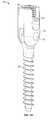
- FIG. 1Ais an isometric view of a pedicle screw assembly in accordance with the present invention.
- FIG. 1Bis an exploded, isometric view of the pedicle screw assembly shown in FIG. 1A .
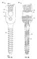
- FIG. 2Ais a side view of the pedicle screw assembly shown hi FIG. 1A .
- FIG. 2Bis a sectional view of the pedicle screw assembly shown in FIG. 2A along line AA.
- FIG. 2Cis a top view of the pedicle screw assembly shown in FIG. 1A .
- FIG. 3Ais a front view of the pedicle screw assembly shown in FIG. 1A .
- FIG. 3Bis a sectional view of the pedicle screw assembly shown in FIG. 3A along line BB.
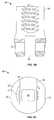
- FIG. 4Ais a partial section view of the pedicle screw assembly shown in FIG. 1A showing swivel head oriented 30 degrees offset from the longitudinal axis of the screw.
- FIG. 4Bis a partial section view of the pedicle screw assembly shown in FIG. 1A showing swivel head oriented 60 degrees offset from the longitudinal axis of the screw.
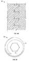
- FIG. 5Ais an isometric view of a pedicle screw according to an assembly embodiment of the present invention shown in FIG. 1A .
- FIG. 5Bis a side view of the pedicle screw shown in FIG. 5A .
- FIG. 5Cis a top view of the pedicle screw shown in FIG. 5A .
- FIG. 5Dis a sectional view of the pedicle screw shown in FIG. 5B along line AA.
- FIG. 5Eis a detailed view of the segment B of the sectional pedicle screw shown in FIG. 5D .
- FIG. 6Ais a side view of a swivel top head according to an assembly embodiment of the present invention shown in FIG. 1A .
- FIG. 6Bis a sectional view of the swivel top head shown in FIG. 6A along line AA.
- FIG. 6Cis a top view of the swivel top head shown in FIG. 6A .
- FIG. 7Ais a front view of a swivel top head according to an assembly embodiment of the present invention shown in FIG. 1A .
- FIG. 7Bis a sectional view of the swivel top head shown in FIG. 7A along line BB.
- FIG. 7Cis a sectional view of the detail area C of swivel top head shown in FIG. 7B .
- FIG. 8Ais a side view of a set screw according to an assembly embodiment of the present invention shown in FIG. 1A .
- FIG. 8Bis a sectional view of the set screw shown in FIG. 8A along line AA.
- FIG. 8Cis a sectional view of the detail area B of the set screw shown in FIG. 8B .
- FIG. 8Dis a partial, sectional view of the set screw shown in FIG. 8A .
- FIG. 8Eis a top view of the set screw shown in FIG. 8A .
- FIG. 9Ais an end view of a conforming washer according to an assembly embodiment of the present invention shown in FIG. 1A .
- FIG. 9Bis a sectional view of the conforming washer shown in FIG. 9A along line AA.
- FIG. 9Cis a bottom view of the conforming washer shown in FIG. 9A .
- FIG. 10Ais a side view of a stepped axel according to an assembly embodiment of the present invention shown in FIG. 1A .
- FIG. 10Bis an end view of the stepped axel shown in FIG. 10B .
- FIG. 11Ais a sectional view of a rod reduction system engaged to a swivel head of the assembly shown in FIG. 1A prior to reduction of the rod into the swivel head's rod receiving area.
- FIG. 11Bis another sectional view of the rod reduction system engaged to a swivel head shown in FIG. 1B after reduction of the rod into the swivel head's rod receiving area.
- FIG. 1Ais an isometric view of a pedicle screw assembly 10 in accordance with the present invention.
- FIG. 1Bis an exploded, isometric view of the pedicle screw assembly 10 shown in FIG. 1A .
- the pedicle screw assembly 10includes a pedicle screw 20 , a swivel top head 30 , a set screw 50 , a conforming washer 60 , and a stepped axel 70 .
- the swivel top head 30is coupled the screw 20 via the stepped axel 70 .
- the conforming washeris rotatably coupled to the set screw 50 .
- FIG. 2Ais a side view of the pedicle screw assembly 10 shown in FIG. 1A
- FIG. 2Bis a sectional view of the pedicle screw assembly 10 shown in FIG. 2A along line AA
- FIG. 2Cis a top view of the pedicle screw assembly 10 shown in FIG. 1A
- the pedicle screw 20may be cannulated 22 .
- a guide wire(not shown) may first be securely placed in a pedicle. Then the pedicle screw assembly 10 without the set screw 50 and conforming washer 60 pair may be inserted over the guide wire to the pedicle via the cannulation 22 . The screw 20 may then be advanced into the pedicle boney process and the guide wire removed from the pedicle bony process via the cannulation 22 .
- FIG. 3Ais a front view of the pedicle screw assembly 10 shown in FIG. 1A and FIG. 3B is a sectional view of the pedicle screw assembly shown in FIG. 3A along line BB.
- the stepped axel 70extends through the pedicle screw 20 into the swivel top head 30 .
- FIG. 3Balso shows the conforming washing integrated within the set screw 50 .
- the conforming washer 60is rotatably integrated or coupled to the set screw 50 .
- FIG. 4Ais a partial sectional view of the pedicle screw assembly 10 shown in FIG. 1A showing the swivel head 30 oriented 30 degrees offset from the longitudinal axis of the screw 20 along a single plane, mono-planar relative to the screw axis.
- FIG. 4Bis a partial sectional view of the pedicle screw assembly 10 shown in FIG. 1A showing the swivel head 30 oriented 60 degrees offset from the longitudinal axis of the screw 20 .
- the pedicle screw 20may have a scalloped shank 24 having a predetermined number of scallops. The scallops may have a concave shape to engage a rounded rod 80 (see FIG. 11A ).
- the scallopsmay have different shapes as a function of the rod shape 80 .
- a rod 80may be inserted into the swivel head 30 .
- the set screw 50 and conforming washer 60may be inserted to compress the rod 80 against a scallop 24 of the screw 20 to maintain the desired orientation.
- FIG. 5Ais an isometric view of a pedicle screw 20 according to an assembly embodiment of the present invention shown in FIG. 1A .
- FIG. 5Bis a side view of the pedicle screw 20 shown in FIG. 5A .
- FIG. 5Cis a top view of the pedicle screw 20 shown in FIG. 5A .
- FIG. 5Dis a sectional view of the pedicle screw 20 shown in FIG. 5B along line AA.
- the pedicle screw 20includes screw cannulation 22 , plurality of scallops 24 , threads, shank axel cannulation 28 , and tip 29 .
- the screw 20 tip 29may be have a chamfer of about 60 degrees.
- a cannulated screw tap(not shown) may be inserted over the guide wire.
- the cannulated screw tapmay then be used to create a tap within the pedicle boney process.
- the screw 20includes the chamfered tip 29 to aid insertion into the tapped pedicle boney process, m one embodiment the screw 20 is inserted in a minimally invasive process so a practitioner may not be able to visual orient the screw within the formed pedicle tap.
- FIGS. 5B , 5 C, and 5 Dalso include some dimensions. It is noted that the pedicle screw assembly 10 may work with screws 20 having different length and radii as a function of patient anatomy, in addition, the scallop dimensions and shape may vary as a function of the rod 80 to be employed with the pedicle screw assembly, in one embodiment the pedicle screw assembly consists primarily of titanium.
- FIG. 5Eis a detailed view of the segment B (threads 26 ) of the sectional pedicle screw 20 shown in FIG. 5D .
- the thread pattern 26is one embodiment in accordance with the present invention and the dimensions are also according to one embodiment in accordance with the present invention.
- FIG. 6Ais a side view of a swivel top head 30 according to an assembly embodiment of the present invention shown in FIG. 1A .
- FIG. 6Bis a sectional view of the swivel top head 30 shown in FIG. 6A along line AA.
- FIG. 6Cis a top view of the swivel top head 30 shown in FIG. 6A .
- the swivel top head 30includes a head axel cannulation 32 , left head arm 34 , right head arm 36 , head receiving channel 38 , head rod seating area 42 , female thread 44 , and screw 20 shank receiving area 46 .
- the left head arm 34 and right head arm 36each include the female thread 44 .
- FIGS. 6B and 6Cinclude dimensions for one embodiment of a swivel top head 30 in accordance with the present invention.
- FIG. 7Ais a front view of a swivel top head 30 according to an assembly embodiment 10 of the present invention shown in FIG. 1A and FIG. 7B is a sectional view of the swivel top head 30 shown in FIG. 7A along line BB.
- FIGS. 7A and 7Binclude dimensions for one embodiment of a swivel top head 30 in accordance with the present invention. As shown in FIG. 7A the swivel top head 30 includes a head axel cannulation offset 48 .
- FIG. 7Cis a sectional view of the detail area C of swivel top head 30 female thread 44 shown in FIG. 7B .
- the thread 44includes a female thread lower rail 43 and a female thread upper rail.
- FIG. 7Cincludes dimensions for one embodiment of a female thread 44 for a swivel top head 30 in accordance with the present invention.
- the thread rails 43 and 45are upwardly inclined. In a process where the set screw 50 is inserted into the left and right arms, the thread pattern 44 will prevent splaying of the arms 34 and 36 .
- FIG. 8Ais a side view of a set screw 50 according to an assembly embodiment of the present invention shown in FIG. 1A .
- FIG. 8Bis a sectional view of the set screw 50 shown in FIG. 8A along line AA.
- FIG. 8Cis a sectional view of the detail area B of the set screw 50 shown in FIG. 8B .
- FIG. 8Dis a partial, sectional view of the set screw 50 shown in FIG. 8A .
- FIG. 8Eis a top view of the set screw 50 shown in FIG. 8A .
- FIGS. 8B and 8Cinclude dimensions for one embodiment of a set screw 50 in accordance with the present invention.
- the set screw 50includes a thread 52 , conforming washer head receiving chamber 56 , and set screw hexagonal key 58 .
- the male thread 52includes lower edge 51 and upper edge 54 .
- the thread 52is dimensioned to match with the female thread 44 to engage the arms 34 and 36 and prevent or limit splaying of the arms 34 and 36 .
- the receiving chamber 56may also include a receiving chamber edge 57 .
- FIG. 9Ais an end view of a conforming washer 60 according to an assembly embodiment of the present invention shown in FIG. 1A .
- FIG. 9Bis a sectional view of the conforming washer 60 shown in FIG. 9A along line AA.
- FIG. 9Cis a bottom view of the conforming washer 60 shown in FIG. 9A .
- FIGS. 9A , 9 B and 9 Cinclude dimensions for one embodiment of a conforming washer 60 in accordance with the present invention.
- the conforming washer 60includes a washer head 62 , washer head enlarged cap 63 , rod conforming section 64 , and rod conforming section reduced ends 65 .
- the washer head 62is dimensioned to be inserted into the washer head receiving chamber 56 .
- the head enlarged cap 63is dimensioned to prevent the conforming washer from being disengaged from the set screw 50 upon insertion into the set screw's receiving chamber 56 while enabling the set screw 50 to be rotated independently of the conforming washer 60 .
- the rod conforming section 64includes reduced ends 65 that cause the conforming washer 60 bend a rod 80 when the set screw 50 compresses the conforming washer against the rod 80 (and screw shank scallops 24 ).
- the conforming washer 60helps the rod 80 meet the natural lordosis of one or more vertebrae (not shown) that the rod 80 may be coupled thereto via the pedicle screw assembly 10 .
- FIG. 10Ais a side view of a stepped axel 70 according to an assembly embodiment 10 of the present invention shown in FIG. 1A .
- FIG. 10Bis an end view of the stepped axel 70 shown in FIG. 1B .
- FIG. 10Aincludes dimensions for one embodiment of a stepped axel 70 in accordance with the present invention.
- the stepped axel 70includes an axel first section 72 , an axel second section 74 , an axel first section leading edge 76 , and an axel second section edge 78 .
- the stepped axel 70is dimensioned to engage the swivel top head 30 shank receiving area while permitting the pedicle screw 20 to rotate freely thereabout via its shank axel cannulation 28 .
- FIG. 11Ais a sectional view of a rod reduction system engaged to a swivel head 30 of the assembly 10 shown in FIG. 1A prior to reduction of the rod 80 into the swivel head's rod receiving area 38 .
- the rod reduction systemincludes head engaging cannula 90 and reduction cannula 100 .
- the head engaging cannula 90includes first arm 94 and a second arm 96 .
- the cannula 90may be placed over the rod 80 after the swivel top head 30 with pedicle screw 20 is inserted in a pedicle boney process.
- the cannula 90 's left and right arm 92 and 94engage the swivel top head's 30 left and right arm 34 and 36 .
- the cannula 90is open between its arms 92 and 94 .
- the cannulais advanced over the cannula 90 to engage the rod 80 and reduce the rod into the swivel top head's 30 rod receiving area 38 .
- the cannulais dimensioned to slide securely over the cannula 90 .
- FIG. 11Bis another sectional view of the rod reduction system where the cannula 90 is engaged to the swivel top head 30 and the rod has been reduced into the swivel top head 30 via the advancement of the cannula over the cannula 90 .
Landscapes
- Health & Medical Sciences (AREA)
- Orthopedic Medicine & Surgery (AREA)
- Life Sciences & Earth Sciences (AREA)
- Surgery (AREA)
- Neurology (AREA)
- Heart & Thoracic Surgery (AREA)
- Engineering & Computer Science (AREA)
- Biomedical Technology (AREA)
- Nuclear Medicine, Radiotherapy & Molecular Imaging (AREA)
- Medical Informatics (AREA)
- Molecular Biology (AREA)
- Animal Behavior & Ethology (AREA)
- General Health & Medical Sciences (AREA)
- Public Health (AREA)
- Veterinary Medicine (AREA)
- Surgical Instruments (AREA)
Abstract
Description
Claims (20)
Priority Applications (1)
| Application Number | Priority Date | Filing Date | Title |
|---|---|---|---|
| US12/848,027US8298268B2 (en) | 2005-04-27 | 2010-07-30 | Mono-planar pedicle screw method, system and kit |
Applications Claiming Priority (4)
| Application Number | Priority Date | Filing Date | Title |
|---|---|---|---|
| US67574205P | 2005-04-27 | 2005-04-27 | |
| PCT/US2006/016042WO2006116606A2 (en) | 2005-04-27 | 2006-04-27 | Mono-planar pedilcle screw method, system, and kit |
| US91627707A | 2007-11-30 | 2007-11-30 | |
| US12/848,027US8298268B2 (en) | 2005-04-27 | 2010-07-30 | Mono-planar pedicle screw method, system and kit |
Related Parent Applications (3)
| Application Number | Title | Priority Date | Filing Date |
|---|---|---|---|
| US11/916,277ContinuationUS7780706B2 (en) | 2005-04-27 | 2006-04-27 | Mono-planar pedicle screw method, system and kit |
| PCT/US2006/016042ContinuationWO2006116606A2 (en) | 2005-04-27 | 2006-04-27 | Mono-planar pedilcle screw method, system, and kit |
| US91627707AContinuation | 2005-04-27 | 2007-11-30 |
Publications (2)
| Publication Number | Publication Date |
|---|---|
| US20100298890A1 US20100298890A1 (en) | 2010-11-25 |
| US8298268B2true US8298268B2 (en) | 2012-10-30 |
Family
ID=37215510
Family Applications (2)
| Application Number | Title | Priority Date | Filing Date |
|---|---|---|---|
| US11/916,277Active - Reinstated2027-03-19US7780706B2 (en) | 2005-04-27 | 2006-04-27 | Mono-planar pedicle screw method, system and kit |
| US12/848,027Expired - Fee RelatedUS8298268B2 (en) | 2005-04-27 | 2010-07-30 | Mono-planar pedicle screw method, system and kit |
Family Applications Before (1)
| Application Number | Title | Priority Date | Filing Date |
|---|---|---|---|
| US11/916,277Active - Reinstated2027-03-19US7780706B2 (en) | 2005-04-27 | 2006-04-27 | Mono-planar pedicle screw method, system and kit |
Country Status (4)
| Country | Link |
|---|---|
| US (2) | US7780706B2 (en) |
| EP (1) | EP1876975A2 (en) |
| CA (1) | CA2614898C (en) |
| WO (1) | WO2006116606A2 (en) |
Cited By (5)
| Publication number | Priority date | Publication date | Assignee | Title |
|---|---|---|---|---|
| US20120116458A1 (en)* | 2010-11-08 | 2012-05-10 | Warsaw Orthopedic, Inc. | Modular pivotable screw assembly and method |
| US20130023935A1 (en)* | 2008-10-10 | 2013-01-24 | Khiem Pham | Uniplanar Screw |
| US9572599B1 (en) | 2009-11-11 | 2017-02-21 | Nuvasive, Inc. | Systems and methods for correcting spinal deformities |
| US10898240B2 (en) | 2016-11-18 | 2021-01-26 | Jgmg Bengochea, Llc | Implants and instruments for enhancing vertebral alignment and sagittal balance |
| US11311316B2 (en)* | 2020-09-04 | 2022-04-26 | Warsaw Orthopedic, Inc. | Spinal implant system and methods of use |
Families Citing this family (110)
| Publication number | Priority date | Publication date | Assignee | Title |
|---|---|---|---|---|
| US7833250B2 (en) | 2004-11-10 | 2010-11-16 | Jackson Roger P | Polyaxial bone screw with helically wound capture connection |
| US7862587B2 (en) | 2004-02-27 | 2011-01-04 | Jackson Roger P | Dynamic stabilization assemblies, tool set and method |
| US8876868B2 (en) | 2002-09-06 | 2014-11-04 | Roger P. Jackson | Helical guide and advancement flange with radially loaded lip |
| WO2006052796A2 (en) | 2004-11-10 | 2006-05-18 | Jackson Roger P | Helical guide and advancement flange with break-off extensions |
| US8172885B2 (en) | 2003-02-05 | 2012-05-08 | Pioneer Surgical Technology, Inc. | Bone plate system |
| US7621918B2 (en) | 2004-11-23 | 2009-11-24 | Jackson Roger P | Spinal fixation tool set and method |
| US7377923B2 (en) | 2003-05-22 | 2008-05-27 | Alphatec Spine, Inc. | Variable angle spinal screw assembly |
| US8377102B2 (en)* | 2003-06-18 | 2013-02-19 | Roger P. Jackson | Polyaxial bone anchor with spline capture connection and lower pressure insert |
| US7967850B2 (en) | 2003-06-18 | 2011-06-28 | Jackson Roger P | Polyaxial bone anchor with helical capture connection, insert and dual locking assembly |
| US8398682B2 (en) | 2003-06-18 | 2013-03-19 | Roger P. Jackson | Polyaxial bone screw assembly |
| US7766915B2 (en) | 2004-02-27 | 2010-08-03 | Jackson Roger P | Dynamic fixation assemblies with inner core and outer coil-like member |
| US7776067B2 (en) | 2005-05-27 | 2010-08-17 | Jackson Roger P | Polyaxial bone screw with shank articulation pressure insert and method |
| US8137386B2 (en) | 2003-08-28 | 2012-03-20 | Jackson Roger P | Polyaxial bone screw apparatus |
| US8926670B2 (en) | 2003-06-18 | 2015-01-06 | Roger P. Jackson | Polyaxial bone screw assembly |
| US11419642B2 (en) | 2003-12-16 | 2022-08-23 | Medos International Sarl | Percutaneous access devices and bone anchor assemblies |
| US7527638B2 (en) | 2003-12-16 | 2009-05-05 | Depuy Spine, Inc. | Methods and devices for minimally invasive spinal fixation element placement |
| US7179261B2 (en) | 2003-12-16 | 2007-02-20 | Depuy Spine, Inc. | Percutaneous access devices and bone anchor assemblies |
| US11241261B2 (en) | 2005-09-30 | 2022-02-08 | Roger P Jackson | Apparatus and method for soft spinal stabilization using a tensionable cord and releasable end structure |
| US7160300B2 (en) | 2004-02-27 | 2007-01-09 | Jackson Roger P | Orthopedic implant rod reduction tool set and method |
| JP2007525274A (en) | 2004-02-27 | 2007-09-06 | ロジャー・ピー・ジャクソン | Orthopedic implant rod reduction instrument set and method |
| US8152810B2 (en) | 2004-11-23 | 2012-04-10 | Jackson Roger P | Spinal fixation tool set and method |
| US7651502B2 (en) | 2004-09-24 | 2010-01-26 | Jackson Roger P | Spinal fixation tool set and method for rod reduction and fastener insertion |
| US8926672B2 (en) | 2004-11-10 | 2015-01-06 | Roger P. Jackson | Splay control closure for open bone anchor |
| US8308782B2 (en) | 2004-11-23 | 2012-11-13 | Jackson Roger P | Bone anchors with longitudinal connecting member engaging inserts and closures for fixation and optional angulation |
| WO2006057837A1 (en) | 2004-11-23 | 2006-06-01 | Jackson Roger P | Spinal fixation tool attachment structure |
| US8444681B2 (en) | 2009-06-15 | 2013-05-21 | Roger P. Jackson | Polyaxial bone anchor with pop-on shank, friction fit retainer and winged insert |
| US9168069B2 (en) | 2009-06-15 | 2015-10-27 | Roger P. Jackson | Polyaxial bone anchor with pop-on shank and winged insert with lower skirt for engaging a friction fit retainer |
| US9980753B2 (en) | 2009-06-15 | 2018-05-29 | Roger P Jackson | pivotal anchor with snap-in-place insert having rotation blocking extensions |
| US10076361B2 (en) | 2005-02-22 | 2018-09-18 | Roger P. Jackson | Polyaxial bone screw with spherical capture, compression and alignment and retention structures |
| US7955358B2 (en) | 2005-09-19 | 2011-06-07 | Albert Todd J | Bone screw apparatus, system and method |
| GB0521582D0 (en) | 2005-10-22 | 2005-11-30 | Depuy Int Ltd | An implant for supporting a spinal column |
| US8100946B2 (en) | 2005-11-21 | 2012-01-24 | Synthes Usa, Llc | Polyaxial bone anchors with increased angulation |
| EP1951159B1 (en) | 2005-11-23 | 2015-08-19 | Trinity Orthopedics | Percutaneous transpedicular access, fusion, discectomy, and stabilization system |
| GB0600662D0 (en) | 2006-01-13 | 2006-02-22 | Depuy Int Ltd | Spinal support rod kit |
| US8348952B2 (en) | 2006-01-26 | 2013-01-08 | Depuy International Ltd. | System and method for cooling a spinal correction device comprising a shape memory material for corrective spinal surgery |
| EP1891904B1 (en)* | 2006-08-24 | 2013-12-25 | Biedermann Technologies GmbH & Co. KG | Bone anchoring device |
| ES2334811T3 (en)* | 2006-11-17 | 2010-03-16 | Biedermann Motech Gmbh | OSEO ANCHORAGE DEVICE. |
| CA2670988C (en) | 2006-12-08 | 2014-03-25 | Roger P. Jackson | Tool system for dynamic spinal implants |
| US8636783B2 (en)* | 2006-12-29 | 2014-01-28 | Zimmer Spine, Inc. | Spinal stabilization systems and methods |
| AU2008206396A1 (en)* | 2007-01-12 | 2008-07-24 | Lanx, Inc. | Bone fastener assembly |
| US10792074B2 (en) | 2007-01-22 | 2020-10-06 | Roger P. Jackson | Pivotal bone anchor assemly with twist-in-place friction fit insert |
| US8979904B2 (en) | 2007-05-01 | 2015-03-17 | Roger P Jackson | Connecting member with tensioned cord, low profile rigid sleeve and spacer with torsion control |
| US8048128B2 (en)* | 2007-06-05 | 2011-11-01 | Spartek Medical, Inc. | Revision system and method for a dynamic stabilization and motion preservation spinal implantation system and method |
| US8623019B2 (en) | 2007-07-03 | 2014-01-07 | Pioneer Surgical Technology, Inc. | Bone plate system |
| US8361126B2 (en) | 2007-07-03 | 2013-01-29 | Pioneer Surgical Technology, Inc. | Bone plate system |
| US9439681B2 (en) | 2007-07-20 | 2016-09-13 | DePuy Synthes Products, Inc. | Polyaxial bone fixation element |
| US20090062914A1 (en)* | 2007-08-29 | 2009-03-05 | Marino James F | Devices and methods for intervertebral therapy |
| DE102007042959B4 (en) | 2007-08-30 | 2011-03-31 | Aesculap Ag | Surgical retaining screw |
| DE102007042953B4 (en)* | 2007-08-30 | 2015-01-22 | Aesculap Ag | Orthopedic retention system |
| US8057518B2 (en)* | 2007-08-31 | 2011-11-15 | Depuy Spine, Inc. | Spanning connector for connecting a spinal fixation element and an offset bone anchor |
| US8025682B2 (en)* | 2007-08-31 | 2011-09-27 | Depuy Spine, Inc. | Method and system for securing a rod to a bone anchor with a connector |
| GB0720762D0 (en)* | 2007-10-24 | 2007-12-05 | Depuy Spine Sorl | Assembly for orthopaedic surgery |
| US8021400B2 (en)* | 2007-12-13 | 2011-09-20 | Trinity Orthopedics Llc | Spinal transverse connector |
| US20090264926A1 (en)* | 2008-04-19 | 2009-10-22 | Warsaw Orthopedic, Inc. | Spinal Fixation System |
| AU2010260521C1 (en) | 2008-08-01 | 2013-08-01 | Roger P. Jackson | Longitudinal connecting member with sleeved tensioned cords |
| JP5815407B2 (en) | 2008-09-12 | 2015-11-17 | ジンテス ゲゼルシャフト ミット ベシュレンクテル ハフツング | Spinal stabilization and guided fixation system |
| KR20110081208A (en) | 2008-09-29 | 2011-07-13 | 신세스 게엠바하 | Multi-Axis Bottom-Loading Screw and Rod Assemblies |
| US8951289B2 (en)* | 2008-10-09 | 2015-02-10 | Total Connect Spine, Llc | Spinal connection assembly |
| WO2010045383A2 (en) | 2008-10-14 | 2010-04-22 | Trinity Orthopedics, Llc | Insertion and reduction tool for pedicle screw assembly |
| CA2742399A1 (en)* | 2008-11-03 | 2010-06-03 | Dustin M. Harvey | Uni-planar bone fixation assembly |
| CN102256558A (en)* | 2008-12-17 | 2011-11-23 | 斯恩蒂斯有限公司 | Rod reducer apparatus for spinal corrective surgery |
| US20100211105A1 (en)* | 2009-02-13 | 2010-08-19 | Missoum Moumene | Telescopic Rod For Posterior Dynamic Stabilization |
| KR20120013312A (en) | 2009-04-15 | 2012-02-14 | 신세스 게엠바하 | Orthodontic Connectors for Spinal Structures |
| US8439925B2 (en) | 2009-05-11 | 2013-05-14 | Trinity Orthopedics, Llc | Transiliac-transsacral method of performing lumbar spinal interventions |
| US20100292739A1 (en)* | 2009-05-15 | 2010-11-18 | Warsaw Orthopedic, Inc. | Bone Screws With Improved Locking Mechanisms |
| US8998959B2 (en) | 2009-06-15 | 2015-04-07 | Roger P Jackson | Polyaxial bone anchors with pop-on shank, fully constrained friction fit retainer and lock and release insert |
| US11229457B2 (en) | 2009-06-15 | 2022-01-25 | Roger P. Jackson | Pivotal bone anchor assembly with insert tool deployment |
| CN103826560A (en) | 2009-06-15 | 2014-05-28 | 罗杰.P.杰克逊 | Polyaxial Bone Anchor with Socket Stem and Winged Inserts with Friction Fit Compression Collars |
| CA2764841A1 (en) | 2009-06-17 | 2010-12-23 | Synthes Usa, Llc | Revision connector for spinal constructs |
| EP2485654B1 (en) | 2009-10-05 | 2021-05-05 | Jackson P. Roger | Polyaxial bone anchor with non-pivotable retainer and pop-on shank, some with friction fit |
| US9044272B2 (en) | 2009-11-09 | 2015-06-02 | Ebi, Llc | Multiplanar bone anchor system |
| US8449578B2 (en)* | 2009-11-09 | 2013-05-28 | Ebi, Llc | Multiplanar bone anchor system |
| US8419778B2 (en) | 2010-01-15 | 2013-04-16 | Ebi, Llc | Uniplanar bone anchor system |
| US8647370B2 (en)* | 2010-01-15 | 2014-02-11 | Ebi, Llc | Uniplanar bone anchor system |
| WO2011127065A1 (en) | 2010-04-06 | 2011-10-13 | Seaspine, Inc. | System and methods for correcting spinal deformities |
| FR2958531B1 (en)* | 2010-04-07 | 2012-08-31 | Michel Timoteo | DEVICE FOR PIVOT INDEXING AND GROOVING THE POLY AXIALITY OF A PEDICULAR SCREW |
| US12383311B2 (en) | 2010-05-14 | 2025-08-12 | Roger P. Jackson | Pivotal bone anchor assembly and method for use thereof |
| US9084634B1 (en) | 2010-07-09 | 2015-07-21 | Theken Spine, Llc | Uniplanar screw |
| US10603083B1 (en) | 2010-07-09 | 2020-03-31 | Theken Spine, Llc | Apparatus and method for limiting a range of angular positions of a screw |
| DE102010040236A1 (en)* | 2010-09-03 | 2012-03-08 | Aces Gmbh | Dynamic stabilization device for joints or spinal column segments, having head region that is connected to fixing block via joint kinematics |
| AU2011324058A1 (en) | 2010-11-02 | 2013-06-20 | Roger P. Jackson | Polyaxial bone anchor with pop-on shank and pivotable retainer |
| CN102551856B (en)* | 2011-01-24 | 2014-07-09 | 上海锐植医疗器械有限公司 | Internal fixing system capable of dilating wound of spinal column in self-rotation manner |
| JP5865479B2 (en) | 2011-03-24 | 2016-02-17 | ロジャー・ピー・ジャクソン | Multiaxial bone anchor with compound joint and pop-mounted shank |
| US9907592B2 (en) | 2011-05-06 | 2018-03-06 | Syberspine Limited | Self guiding surgical bone fixation screw |
| US8784424B2 (en)* | 2011-06-16 | 2014-07-22 | Industrial Technology Research Institute | Minimally invasive spinal stabilization system |
| TWI468143B (en)* | 2011-06-16 | 2015-01-11 | Ind Tech Res Inst | Minimally invasive spinal stabilization system |
| KR101276183B1 (en) | 2011-07-01 | 2013-06-18 | 주식회사 지에스메디칼 | Pedicle screw assembly |
| EP2747670A4 (en) | 2011-10-05 | 2015-06-24 | Mark A Dodson | Modular retractor and related method |
| US10016220B2 (en) | 2011-11-01 | 2018-07-10 | Nuvasive Specialized Orthopedics, Inc. | Adjustable magnetic devices and methods of using same |
| US8911479B2 (en) | 2012-01-10 | 2014-12-16 | Roger P. Jackson | Multi-start closures for open implants |
| US8911478B2 (en) | 2012-11-21 | 2014-12-16 | Roger P. Jackson | Splay control closure for open bone anchor |
| US10058354B2 (en) | 2013-01-28 | 2018-08-28 | Roger P. Jackson | Pivotal bone anchor assembly with frictional shank head seating surfaces |
| US8852239B2 (en) | 2013-02-15 | 2014-10-07 | Roger P Jackson | Sagittal angle screw with integral shank and receiver |
| WO2014153167A1 (en) | 2013-03-14 | 2014-09-25 | The Raph Life, Llc | Surgical system device without the use of a guide wire |
| US9987047B2 (en) | 2013-10-07 | 2018-06-05 | Spine Wave, Inc. | Translating polyaxial screw |
| US20150100077A1 (en) | 2013-10-09 | 2015-04-09 | Safewire, LLC | Thread forming jamshidi assembly |
| US9566092B2 (en) | 2013-10-29 | 2017-02-14 | Roger P. Jackson | Cervical bone anchor with collet retainer and outer locking sleeve |
| US9717533B2 (en) | 2013-12-12 | 2017-08-01 | Roger P. Jackson | Bone anchor closure pivot-splay control flange form guide and advancement structure |
| US9451993B2 (en) | 2014-01-09 | 2016-09-27 | Roger P. Jackson | Bi-radial pop-on cervical bone anchor |
| US10064658B2 (en) | 2014-06-04 | 2018-09-04 | Roger P. Jackson | Polyaxial bone anchor with insert guides |
| US9597119B2 (en) | 2014-06-04 | 2017-03-21 | Roger P. Jackson | Polyaxial bone anchor with polymer sleeve |
| WO2016172677A1 (en)* | 2015-04-24 | 2016-10-27 | K2M, Inc. | Tethering screw system |
| DE102016113495A1 (en) | 2016-07-21 | 2018-01-25 | Aesculap Ag | Pedicle screw system with a locking screw with threaded section |
| US10507043B1 (en) | 2017-10-11 | 2019-12-17 | Seaspine Orthopedics Corporation | Collet for a polyaxial screw assembly |
| US12011312B2 (en) | 2017-10-20 | 2024-06-18 | Trinity Orthopedics, Llc | Image based positioning and guidance system and methods of use |
| AU2019398345B2 (en)* | 2018-12-12 | 2025-09-11 | Orthopediatrics Corp. | Bone anchor head extender |
| US20220160400A1 (en)* | 2019-03-12 | 2022-05-26 | Carbofix Spine Inc. | Composite material spinal implant |
| WO2021127251A1 (en)* | 2019-12-17 | 2021-06-24 | Jackson Roger P | Bone anchor assembly with closed ring retainer and internal snap ring |
| US20210186565A1 (en)* | 2019-12-20 | 2021-06-24 | Warsaw Orthopedic, Inc. | Anti-Splay Head and Set Screw for Spinal Fixation |
| US11877779B2 (en) | 2020-03-26 | 2024-01-23 | Xtant Medical Holdings, Inc. | Bone plate system |
Citations (174)
| Publication number | Priority date | Publication date | Assignee | Title |
|---|---|---|---|---|
| US4519100A (en) | 1982-09-30 | 1985-05-28 | Orthopedic Equipment Co. Inc. | Distal locking intramedullary nail |
| US4827918A (en) | 1985-08-15 | 1989-05-09 | Sven Olerud | Fixing instrument for use in spinal surgery |
| US4862883A (en) | 1988-04-21 | 1989-09-05 | Yosef Freeland | Interlocking intramedullary nail |
| US4987892A (en) | 1989-04-04 | 1991-01-29 | Krag Martin H | Spinal fixation device |
| US5034011A (en) | 1990-08-09 | 1991-07-23 | Advanced Spine Fixation Systems Incorporated | Segmental instrumentation of the posterior spine |
| US5057109A (en) | 1989-10-16 | 1991-10-15 | Sven Olerud | Fixing instruments for spinal surgery |
| US5190543A (en) | 1990-11-26 | 1993-03-02 | Synthes (U.S.A.) | Anchoring device |
| US5261909A (en) | 1992-02-18 | 1993-11-16 | Danek Medical, Inc. | Variable angle screw for spinal implant system |
| US5300074A (en) | 1990-12-17 | 1994-04-05 | Synthes (U.S.A.) | Two-part angle plate |
| US5308327A (en) | 1991-11-25 | 1994-05-03 | Advanced Surgical Inc. | Self-deployed inflatable retractor |
| US5312402A (en) | 1991-04-16 | 1994-05-17 | Synthes (U.S.A.) | Connection device |
| US5423826A (en) | 1993-02-05 | 1995-06-13 | Danek Medical, Inc. | Anterior cervical plate holder/drill guide and method of use |
| US5468241A (en) | 1988-02-18 | 1995-11-21 | Howmedica Gmbh | Support device for the human vertebral column |
| US5476464A (en) | 1993-02-25 | 1995-12-19 | Howmedica Gmbh | Device for setting a spine |
| US5499983A (en) | 1994-02-23 | 1996-03-19 | Smith & Nephew Richards, Inc. | Variable angle spinal screw |
| US5536268A (en) | 1992-12-23 | 1996-07-16 | Plus Endoprothetik Ag | System for osteosynthesis at the vertebral column, connecting element for such a system and tool for its placement and removal |
| US5571105A (en) | 1993-07-06 | 1996-11-05 | Gundolf; Ferdinand | Osteosynthesis apparatus for the fixation of bone fragments |
| US5616143A (en) | 1995-02-06 | 1997-04-01 | Schlapfer; Johannes F. | Surgical forceps |
| US5643264A (en) | 1995-09-13 | 1997-07-01 | Danek Medical, Inc. | Iliac screw |
| US5645544A (en) | 1995-09-13 | 1997-07-08 | Danek Medical, Inc. | Variable angle extension rod |
| US5649926A (en) | 1994-07-14 | 1997-07-22 | Advanced Spine Fixation Systems, Inc. | Spinal segmental reduction derotational fixation system |
| US5672176A (en) | 1995-03-15 | 1997-09-30 | Biedermann; Lutz | Anchoring member |
| US5702397A (en) | 1996-02-20 | 1997-12-30 | Medicinelodge, Inc. | Ligament bone anchor and method for its use |
| US5707371A (en) | 1992-02-28 | 1998-01-13 | Howmedica Gmbh | Repositioning tool |
| US5782833A (en) | 1996-12-20 | 1998-07-21 | Haider; Thomas T. | Pedicle screw system for osteosynthesis |
| US5797911A (en) | 1996-09-24 | 1998-08-25 | Sdgi Holdings, Inc. | Multi-axial bone screw assembly |
| US5876403A (en) | 1996-09-06 | 1999-03-02 | Robert Reid Inc. | Bone-fixing devices |
| US5879350A (en) | 1996-09-24 | 1999-03-09 | Sdgi Holdings, Inc. | Multi-axial bone screw assembly |
| US5885286A (en) | 1996-09-24 | 1999-03-23 | Sdgi Holdings, Inc. | Multi-axial bone screw assembly |
| US5891145A (en) | 1997-07-14 | 1999-04-06 | Sdgi Holdings, Inc. | Multi-axial screw |
| US5941879A (en) | 1997-11-18 | 1999-08-24 | Electro-Biology, Inc. | Method and apparatus for external fixation of bones |
| US5976136A (en) | 1998-05-11 | 1999-11-02 | Electro Biology, Inc. | Method and apparatus for external bone fixator |
| US5980557A (en) | 1997-02-05 | 1999-11-09 | Ethicon | Fastener for fastening a muscle tendon to a bone |
| US5989250A (en) | 1996-10-24 | 1999-11-23 | Spinal Concepts, Inc. | Method and apparatus for spinal fixation |
| US6030389A (en) | 1997-08-04 | 2000-02-29 | Spinal Concepts, Inc. | System and method for stabilizing the human spine with a bone plate |
| US6056755A (en) | 1996-05-09 | 2000-05-02 | Horas; Uwe Peter | Method for transporting a bone segment in order to bridge a bone defect and device for carrying out the method |
| US6123706A (en) | 1997-12-17 | 2000-09-26 | Lange; Robert | Apparatus for stabilizing certain vertebrae of the spine |
| US6132430A (en) | 1996-10-24 | 2000-10-17 | Spinal Concepts, Inc. | Spinal fixation system |
| US6155756A (en) | 1998-12-30 | 2000-12-05 | Musculoskeletal Transplant Foundation | Thread forming machine for bone material |
| US6179838B1 (en) | 1998-02-24 | 2001-01-30 | Daniel Fiz | Bone fixation arrangements and method |
| US6214004B1 (en) | 1998-06-09 | 2001-04-10 | Wesley L. Coker | Vertebral triplaner alignment facilitator |
| US6224600B1 (en) | 1996-07-10 | 2001-05-01 | G. Constantine Protogirou | Intramedullary, flexible fracture fixation device, using bi-axial prestressing |
| US6254602B1 (en) | 1999-05-28 | 2001-07-03 | Sdgi Holdings, Inc. | Advanced coupling device using shape-memory technology |
| US20010007941A1 (en) | 1998-08-21 | 2001-07-12 | Beatrice Steiner | Bone anchoring assembly with a snap-in ballhead |
| US20010014807A1 (en) | 1997-08-04 | 2001-08-16 | Erik J. Wagner | System and method for stabilizing the human spine with a bone plate |
| US6280442B1 (en) | 1999-09-01 | 2001-08-28 | Sdgi Holdings, Inc. | Multi-axial bone screw assembly |
| US20010021851A1 (en) | 1998-07-20 | 2001-09-13 | Roland Eberlein | Fastening assembly |
| US20010025181A1 (en) | 1993-03-23 | 2001-09-27 | Yosef Freedlan | Split-nut precision fasteners |
| US20010029376A1 (en) | 1998-05-12 | 2001-10-11 | Sater Ghaleb A. | Manual bone anchor placement devices |
| US20010034521A1 (en) | 2000-02-16 | 2001-10-25 | Bailey Kirk J. | Method and system for spinal fixation |
| US6309391B1 (en) | 2000-03-15 | 2001-10-30 | Sdgi Holding, Inc. | Multidirectional pivoting bone screw and fixation system |
| US6331179B1 (en) | 2000-01-06 | 2001-12-18 | Spinal Concepts, Inc. | System and method for stabilizing the human spine with a bone plate |
| US20020010467A1 (en) | 2000-07-22 | 2002-01-24 | Corin Spinal Systems Limited | Pedicle attachment assembly |
| US6355036B1 (en) | 1999-08-02 | 2002-03-12 | Kyowa Precision Instruments Corp. | Bone adjuster |
| US20020035366A1 (en) | 2000-09-18 | 2002-03-21 | Reto Walder | Pedicle screw for intervertebral support elements |
| US6368321B1 (en) | 2000-12-04 | 2002-04-09 | Roger P. Jackson | Lockable swivel head bone screw |
| US20020055741A1 (en) | 1999-05-14 | 2002-05-09 | Schlapfer Fridolin J. | Bone fixation device with a rotation joint |
| US20020072749A1 (en) | 2000-12-13 | 2002-06-13 | Albert Enayati | Split rivet bone fastener |
| US20020091386A1 (en) | 2001-01-05 | 2002-07-11 | Greg Martin | Pedicle screw assembly |
| US6440133B1 (en) | 2001-07-03 | 2002-08-27 | Sdgi Holdings, Inc. | Rod reducer instruments and methods |
| US20020120268A1 (en) | 2001-02-21 | 2002-08-29 | Roger Berger | Occipital plate and system for spinal stabilization |
| US6454773B1 (en) | 1996-11-07 | 2002-09-24 | Sdgi Holdings, Inc. | Multi-angle bone screw assembly using shape-memory technology |
| US6478798B1 (en) | 2001-05-17 | 2002-11-12 | Robert S. Howland | Spinal fixation apparatus and methods for use |
| US20020173791A1 (en) | 2001-05-17 | 2002-11-21 | Howland Robert S. | Spinal fixation apparatus with enhanced axial support and methods for use |
| US6485518B1 (en) | 1999-12-10 | 2002-11-26 | Nuvasive | Facet screw and bone allograft intervertebral support and fusion system |
| US6530929B1 (en) | 1999-10-20 | 2003-03-11 | Sdgi Holdings, Inc. | Instruments for stabilization of bony structures |
| US20030055426A1 (en) | 2001-09-14 | 2003-03-20 | John Carbone | Biased angulation bone fixation assembly |
| US6537276B2 (en) | 1992-03-02 | 2003-03-25 | Stryker Trauma Gmbh | Apparatus for bracing vertebrae |
| US6554834B1 (en) | 1999-10-07 | 2003-04-29 | Stryker Spine | Slotted head pedicle screw assembly |
| US6554831B1 (en) | 2000-09-01 | 2003-04-29 | Hopital Sainte-Justine | Mobile dynamic system for treating spinal disorder |
| US20030083658A1 (en) | 2001-10-31 | 2003-05-01 | Ortho Development Corporation | Cervical plate for stabilizing the human spine |
| US6558386B1 (en) | 2000-02-16 | 2003-05-06 | Trans1 Inc. | Axial spinal implant and method and apparatus for implanting an axial spinal implant within the vertebrae of the spine |
| US6565565B1 (en) | 1998-06-17 | 2003-05-20 | Howmedica Osteonics Corp. | Device for securing spinal rods |
| US20030105460A1 (en) | 2000-03-15 | 2003-06-05 | Dennis Crandall | Multidirectional pivoting bone screw and fixation system |
| US6575979B1 (en) | 2000-02-16 | 2003-06-10 | Axiamed, Inc. | Method and apparatus for providing posterior or anterior trans-sacral access to spinal vertebrae |
| US20030135214A1 (en) | 2002-01-15 | 2003-07-17 | Fetto Joseph F. | System, device, composition and method for treating and preventing avascular or osteonecrosis |
| US20030149431A1 (en) | 2002-02-01 | 2003-08-07 | Varieur Michael S. | Closure system for spinal fixation instrumentation |
| US6623487B1 (en) | 2001-02-13 | 2003-09-23 | Biomet, Inc. | Temperature sensitive surgical fastener |
| US20030187440A1 (en) | 2002-03-12 | 2003-10-02 | Marc Richelsoph | Bone plate and screw retaining mechanism |
| US20030208203A1 (en) | 2002-05-06 | 2003-11-06 | Roy Lim | Minimally invasive instruments and methods for inserting implants |
| US6648888B1 (en) | 2002-09-06 | 2003-11-18 | Endius Incorporated | Surgical instrument for moving a vertebra |
| US20030220641A1 (en) | 2000-03-07 | 2003-11-27 | Thelen Sarah L. | Method and apparatus for reducing femoral fractures |
| US6660006B2 (en) | 2002-04-17 | 2003-12-09 | Stryker Spine | Rod persuader |
| US20030229345A1 (en) | 2002-06-11 | 2003-12-11 | Stahurski Terrence M. | Connector assembly with multidimensional accommodation and associated method |
| US6663632B1 (en) | 1998-05-19 | 2003-12-16 | Synthes (U.S.A.) | Osteosynthetic implant with an embedded hinge joint |
| US20040015169A1 (en) | 2002-07-16 | 2004-01-22 | Larry Gause | Bone plate fastener retaining mechanisms and methods |
| US6685708B2 (en) | 2000-09-07 | 2004-02-03 | Niti Alloys Technologies Ltd. | Staples for bone fixation |
| US6689133B2 (en) | 1999-04-16 | 2004-02-10 | Sdgi Holdings, Inc. | Multi-axial bone anchor system |
| US20040030336A1 (en) | 2002-08-06 | 2004-02-12 | Khanna Rohit Kumar | Anterior cervical spine stabilization method and system |
| US20040034350A1 (en) | 2000-03-15 | 2004-02-19 | St. Onge Richard A. | Bone setting apparatus and method |
| US20040039387A1 (en) | 2002-08-22 | 2004-02-26 | Larry Gause | System for stabilizing a portion of the spine |
| US20040039384A1 (en) | 2002-08-21 | 2004-02-26 | Boehm Frank H. | Device and method for pertcutaneous placement of lumbar pedicle screws and connecting rods |
| US6699250B1 (en) | 1998-07-13 | 2004-03-02 | Sepitec Foundation | Osteosynthesis screw |
| US20040049197A1 (en) | 1994-12-08 | 2004-03-11 | Jose Vicente Barbera Alacreu | Dorsolumbar and lumbosacral vertebral fixation system |
| US6709434B1 (en) | 1998-07-30 | 2004-03-23 | Sofamor S.N.C. | Spinal osteosynthesis device |
| US20040068319A1 (en) | 2002-10-04 | 2004-04-08 | Cordaro Nicholas M. | Cervical plate/screw system for immobilizing vertebral bodies |
| US20040092934A1 (en) | 2002-04-24 | 2004-05-13 | Howland Robert S. | Multi selective axis spinal fixation system |
| US20040102775A1 (en) | 2002-11-19 | 2004-05-27 | Huebner Randall J. | Bone plates with slots |
| US20040122442A1 (en) | 2002-12-20 | 2004-06-24 | High Plains Technology Group, Llc | Bone screw fastener and apparatus for inserting and removing same |
| US6755828B2 (en) | 2000-02-03 | 2004-06-29 | Russian Ilizarov Scientific Center | Device for external transpedicular spinal fixation, technique of its use |
| US20040133207A1 (en) | 2002-10-11 | 2004-07-08 | Abdou M. Samy | Distraction screw for skeletal surgery and method of use |
| US20040138660A1 (en) | 2003-01-10 | 2004-07-15 | Serhan Hassan A. | Locking cap assembly for spinal fixation instrumentation |
| US20040153070A1 (en) | 2003-02-03 | 2004-08-05 | Barker B. Thomas | Midline occipital vertebral fixation system |
| US20040158247A1 (en) | 2003-02-07 | 2004-08-12 | Arthit Sitiso | Polyaxial pedicle screw system |
| US6800079B2 (en) | 2002-03-15 | 2004-10-05 | Lock-N-Stitch, Inc. | Orthopedic stabilization device and method |
| US20040204711A1 (en) | 2003-04-09 | 2004-10-14 | Jackson Roger P. | Polyaxial bone screw locking mechanism |
| US20040215190A1 (en) | 2003-04-25 | 2004-10-28 | Nguyen Thanh V. | System and method for minimally invasive posterior fixation |
| FR2855392A1 (en)* | 2003-05-28 | 2004-12-03 | Spinevision | CONNECTION DEVICE FOR SPINAL OSTESYNTHESIS |
| US20040254579A1 (en) | 2003-03-20 | 2004-12-16 | Stryker Trauma S.A. | Bone connection device |
| US6833005B1 (en) | 2001-02-02 | 2004-12-21 | John P. Mantas | Ligament graft system and method |
| US20040260297A1 (en) | 2001-03-22 | 2004-12-23 | Martin Padget | Tool for bone fixation device |
| US20040260284A1 (en) | 2003-06-23 | 2004-12-23 | Matthew Parker | Anti-splay pedicle screw |
| US20050010214A1 (en) | 2001-10-17 | 2005-01-13 | Jean-Louis Tassin | System of holding at least two vertebrae together for the purpose of spinal osteosynthesis |
| US20050033298A1 (en) | 2001-10-31 | 2005-02-10 | Ortho Development Corporation | Cervical plate for stabilizing the human spine |
| US20050075633A1 (en) | 2003-10-02 | 2005-04-07 | Thomas Ross | Anterior cervical plate |
| US20050085813A1 (en) | 2003-10-21 | 2005-04-21 | Innovative Spinal Technologies | System and method for stabilizing of internal structures |
| US20050090827A1 (en) | 2003-10-28 | 2005-04-28 | Tewodros Gedebou | Comprehensive tissue attachment system |
| US20050096657A1 (en) | 2002-02-26 | 2005-05-05 | Alex Autericque | Osteosynthesis or arthrodesis material comprising a bony plate |
| US20050119659A1 (en) | 2002-04-09 | 2005-06-02 | Joachim Pfefferle | Distractor |
| US20050131408A1 (en) | 2003-12-16 | 2005-06-16 | Sicvol Christopher W. | Percutaneous access devices and bone anchor assemblies |
| US20050187548A1 (en) | 2004-01-13 | 2005-08-25 | Butler Michael S. | Pedicle screw constructs for spine fixation systems |
| US20050192575A1 (en) | 2004-02-20 | 2005-09-01 | Pacheco Hector O. | Method of improving pedicle screw placement in spinal surgery |
| US20050216003A1 (en) | 2004-03-03 | 2005-09-29 | Biedermann Motech Gmbh | Bone anchoring element for anchoring in a bone or vertebra, and stabilization device with such a bone anchoring element |
| US20050222570A1 (en) | 2003-06-18 | 2005-10-06 | Jackson Roger P | Upload shank swivel head bone screw spinal implant |
| US20050228379A1 (en) | 2003-06-18 | 2005-10-13 | Jackson Roger P | Upload shank swivel head bone screw spinal implant |
| US20050251138A1 (en) | 2003-10-20 | 2005-11-10 | Olevsky Boris | Bone plate and method for using bone plate |
| US20050261687A1 (en) | 2004-04-20 | 2005-11-24 | Laszlo Garamszegi | Pedicle screw assembly |
| US20050277922A1 (en) | 2004-06-09 | 2005-12-15 | Trieu Hai H | Systems and methods for flexible spinal stabilization |
| US20050277919A1 (en) | 2004-05-28 | 2005-12-15 | Depuy Spine, Inc. | Anchoring systems and methods for correcting spinal deformities |
| US20050277925A1 (en) | 2004-06-09 | 2005-12-15 | Mujwid James R | Spinal fixation device with internal drive structure |
| US20050283157A1 (en) | 2004-06-17 | 2005-12-22 | Coates Bradley J | Multi-axial bone attachment assembly |
| US20060004360A1 (en) | 2002-09-04 | 2006-01-05 | Aesculap Ag & Co. Kg | Orthopedic fixation device |
| US20060025771A1 (en) | 2000-08-23 | 2006-02-02 | Jackson Roger P | Helical reverse angle guide and advancement structure with break-off extensions |
| US20060030851A1 (en) | 2003-04-21 | 2006-02-09 | Rsb Spine Llc | Implant subsidence control |
| US20060036240A1 (en) | 2004-08-09 | 2006-02-16 | Innovative Spinal Technologies | System and method for dynamic skeletal stabilization |
| US20060036252A1 (en) | 2004-08-12 | 2006-02-16 | Baynham Bret O | Polyaxial screw |
| US20060047282A1 (en) | 2004-08-30 | 2006-03-02 | Vermillion Technologies, Llc | Implant for correction of spinal deformity |
| US7011685B2 (en) | 2003-11-07 | 2006-03-14 | Impliant Ltd. | Spinal prostheses |
| US20060064092A1 (en) | 2001-05-17 | 2006-03-23 | Howland Robert S | Selective axis serrated rod low profile spinal fixation system |
| US20060079892A1 (en) | 2001-10-31 | 2006-04-13 | Suranjan Roychowdhury | Adjustable tandem connectors for corrective devices for the spinal column and other bones and joints |
| US20060116680A1 (en) | 2004-11-30 | 2006-06-01 | Stryker Trauma Sa | Extractor for a bone connection element |
| US20060122602A1 (en) | 2004-12-08 | 2006-06-08 | Depuy Spine, Inc. | Hybrid spinal plates |
| US20060142767A1 (en) | 2004-12-27 | 2006-06-29 | Green Daniel W | Orthopedic device and method for correcting angular bone deformity |
| US20060155283A1 (en) | 2005-01-07 | 2006-07-13 | Depuy Spine Sarl | Occipital plate and guide systems |
| US20060167454A1 (en) | 2004-11-09 | 2006-07-27 | Depuy Spine, Inc. | Minimally invasive spinal fixation guide systems and methods |
| US20060195096A1 (en) | 2005-02-09 | 2006-08-31 | David Lee | Bone fixation apparatus |
| US20060195086A1 (en) | 2005-02-02 | 2006-08-31 | Syberspine Limited | Integral, articulated, pedicle screw and longitudinal member for spinal osteosynthesis |
| US20060200131A1 (en) | 2005-03-04 | 2006-09-07 | Depuy Spine Sarl | Constrained motion bone screw assembly |
| US20060200129A1 (en) | 2005-02-18 | 2006-09-07 | Aldo Denti | Implants and methods for positioning same in surgical approaches to the spine |
| US20060241595A1 (en) | 2005-04-22 | 2006-10-26 | Sdgi Holdings, Inc. | Force limiting coupling assemblies for spinal implants |
| US20060247650A1 (en) | 2004-12-13 | 2006-11-02 | St. Francis Medical Technologies, Inc. | Inter-cervical facet joint fusion implant |
| US20060282075A1 (en) | 2005-06-10 | 2006-12-14 | Depuy Spine, Inc. | Posterior dynamic stabilization x-device |
| US7160300B2 (en) | 2004-02-27 | 2007-01-09 | Jackson Roger P | Orthopedic implant rod reduction tool set and method |
| US20070010818A1 (en) | 2005-07-06 | 2007-01-11 | Stone Howard A | Surgical system for joints |
| US20070016219A1 (en) | 2005-07-14 | 2007-01-18 | Levine Marc J | Vertebral Marker Devices and Installation Methods |
| US20070016195A1 (en) | 2005-05-10 | 2007-01-18 | Winslow Charles J | Inter-cervical facet implant with implantation tool |
| US20070016200A1 (en) | 2003-04-09 | 2007-01-18 | Jackson Roger P | Dynamic stabilization medical implant assemblies and methods |
| US7166109B2 (en) | 2001-10-23 | 2007-01-23 | Biedermann Motech Gmbh | Bone fixation device and screw therefor |
| US20070043358A1 (en) | 2005-08-05 | 2007-02-22 | Sdgi Holdings, Inc. | Coupling assemblies for spinal implants |
| US20070049931A1 (en) | 2005-08-26 | 2007-03-01 | Sdgi Holdings, Inc. | Instruments for minimally invasive stabilization of bony structures |
| US20070055242A1 (en) | 2005-07-27 | 2007-03-08 | Bailly Frank E | Device for securing spinal rods |
| US20070073405A1 (en) | 2005-09-29 | 2007-03-29 | Dominique Verhulst | Motion segment repair system |
| US20070083202A1 (en) | 2005-09-20 | 2007-04-12 | Donald Eli Running | Intramedullary bone plate with sheath |
| US20070083203A1 (en) | 2005-09-16 | 2007-04-12 | Ribeiro Helio M | Anterior cervical plating system |
| US20070093904A1 (en) | 2005-10-26 | 2007-04-26 | Lutz Biedermann | Implant with one piece swivel joint |
| US20070093821A1 (en) | 2005-09-13 | 2007-04-26 | Stefan Freudiger | Dynamic clamping device for spinal implant |
| US20070093817A1 (en) | 2005-09-29 | 2007-04-26 | Michael Barrus | Spinal fixation system having locking and unlocking devices for use with a multi-planar, taper lock screw |
| US7220262B1 (en) | 2001-03-16 | 2007-05-22 | Sdgi Holdings, Inc. | Spinal fixation system and related methods |
| US20070162044A1 (en) | 2005-11-23 | 2007-07-12 | Trinity Orthopedics | Percutaneous transpedicular access, fusion, discectomy, and stabilization system and method |
| US7377923B2 (en) | 2003-05-22 | 2008-05-27 | Alphatec Spine, Inc. | Variable angle spinal screw assembly |
| US20090062914A1 (en) | 2007-08-29 | 2009-03-05 | Marino James F | Devices and methods for intervertebral therapy |
| US20090105769A1 (en) | 2007-10-22 | 2009-04-23 | Andy Rock | Uni-planar, taper lock bone screw |
| US20090105716A1 (en) | 2007-10-23 | 2009-04-23 | Michael Barrus | Mono-axial, taper lock bone screw |
| US7588593B2 (en) | 2006-04-18 | 2009-09-15 | International Spinal Innovations, Llc | Pedicle screw with vertical adjustment |
Family Cites Families (2)
| Publication number | Priority date | Publication date | Assignee | Title |
|---|---|---|---|---|
| US720262A (en)* | 1902-11-26 | 1903-02-10 | Deering Harvester Company | Mowing-machine. |
| DE9216565U1 (en)* | 1992-12-04 | 1994-03-31 | Waldemar Link GmbH & Co, 22339 Hamburg | Device for connecting bone parts by means of a bone plate |
- 2006
- 2006-04-27CACA2614898Apatent/CA2614898C/enactiveActive
- 2006-04-27USUS11/916,277patent/US7780706B2/enactiveActive - Reinstated
- 2006-04-27EPEP06751652Apatent/EP1876975A2/ennot_activeWithdrawn
- 2006-04-27WOPCT/US2006/016042patent/WO2006116606A2/enactiveApplication Filing
- 2010
- 2010-07-30USUS12/848,027patent/US8298268B2/ennot_activeExpired - Fee Related
Patent Citations (221)
| Publication number | Priority date | Publication date | Assignee | Title |
|---|---|---|---|---|
| US4519100A (en) | 1982-09-30 | 1985-05-28 | Orthopedic Equipment Co. Inc. | Distal locking intramedullary nail |
| US4827918A (en) | 1985-08-15 | 1989-05-09 | Sven Olerud | Fixing instrument for use in spinal surgery |
| US5468241A (en) | 1988-02-18 | 1995-11-21 | Howmedica Gmbh | Support device for the human vertebral column |
| US4862883A (en) | 1988-04-21 | 1989-09-05 | Yosef Freeland | Interlocking intramedullary nail |
| US4987892A (en) | 1989-04-04 | 1991-01-29 | Krag Martin H | Spinal fixation device |
| US5057109A (en) | 1989-10-16 | 1991-10-15 | Sven Olerud | Fixing instruments for spinal surgery |
| US5034011A (en) | 1990-08-09 | 1991-07-23 | Advanced Spine Fixation Systems Incorporated | Segmental instrumentation of the posterior spine |
| US5190543A (en) | 1990-11-26 | 1993-03-02 | Synthes (U.S.A.) | Anchoring device |
| US5300074A (en) | 1990-12-17 | 1994-04-05 | Synthes (U.S.A.) | Two-part angle plate |
| US5312402A (en) | 1991-04-16 | 1994-05-17 | Synthes (U.S.A.) | Connection device |
| US5308327A (en) | 1991-11-25 | 1994-05-03 | Advanced Surgical Inc. | Self-deployed inflatable retractor |
| US5261909A (en) | 1992-02-18 | 1993-11-16 | Danek Medical, Inc. | Variable angle screw for spinal implant system |
| US5707371A (en) | 1992-02-28 | 1998-01-13 | Howmedica Gmbh | Repositioning tool |
| US6537276B2 (en) | 1992-03-02 | 2003-03-25 | Stryker Trauma Gmbh | Apparatus for bracing vertebrae |
| US5536268A (en) | 1992-12-23 | 1996-07-16 | Plus Endoprothetik Ag | System for osteosynthesis at the vertebral column, connecting element for such a system and tool for its placement and removal |
| US5423826A (en) | 1993-02-05 | 1995-06-13 | Danek Medical, Inc. | Anterior cervical plate holder/drill guide and method of use |
| US5476464A (en) | 1993-02-25 | 1995-12-19 | Howmedica Gmbh | Device for setting a spine |
| US20010025181A1 (en) | 1993-03-23 | 2001-09-27 | Yosef Freedlan | Split-nut precision fasteners |
| US5571105A (en) | 1993-07-06 | 1996-11-05 | Gundolf; Ferdinand | Osteosynthesis apparatus for the fixation of bone fragments |
| US5499983A (en) | 1994-02-23 | 1996-03-19 | Smith & Nephew Richards, Inc. | Variable angle spinal screw |
| US5649926A (en) | 1994-07-14 | 1997-07-22 | Advanced Spine Fixation Systems, Inc. | Spinal segmental reduction derotational fixation system |
| US20040049197A1 (en) | 1994-12-08 | 2004-03-11 | Jose Vicente Barbera Alacreu | Dorsolumbar and lumbosacral vertebral fixation system |
| US5616143A (en) | 1995-02-06 | 1997-04-01 | Schlapfer; Johannes F. | Surgical forceps |
| US5672176A (en) | 1995-03-15 | 1997-09-30 | Biedermann; Lutz | Anchoring member |
| US5645544A (en) | 1995-09-13 | 1997-07-08 | Danek Medical, Inc. | Variable angle extension rod |
| US5643264A (en) | 1995-09-13 | 1997-07-01 | Danek Medical, Inc. | Iliac screw |
| US5702397A (en) | 1996-02-20 | 1997-12-30 | Medicinelodge, Inc. | Ligament bone anchor and method for its use |
| US6056755A (en) | 1996-05-09 | 2000-05-02 | Horas; Uwe Peter | Method for transporting a bone segment in order to bridge a bone defect and device for carrying out the method |
| US6224600B1 (en) | 1996-07-10 | 2001-05-01 | G. Constantine Protogirou | Intramedullary, flexible fracture fixation device, using bi-axial prestressing |
| US5876403A (en) | 1996-09-06 | 1999-03-02 | Robert Reid Inc. | Bone-fixing devices |
| US5797911A (en) | 1996-09-24 | 1998-08-25 | Sdgi Holdings, Inc. | Multi-axial bone screw assembly |
| US5879350A (en) | 1996-09-24 | 1999-03-09 | Sdgi Holdings, Inc. | Multi-axial bone screw assembly |
| US5885286A (en) | 1996-09-24 | 1999-03-23 | Sdgi Holdings, Inc. | Multi-axial bone screw assembly |
| US6595992B1 (en) | 1996-10-24 | 2003-07-22 | Spinal Concepts, Inc. | Method and apparatus for spinal fixation |
| US6132430A (en) | 1996-10-24 | 2000-10-17 | Spinal Concepts, Inc. | Spinal fixation system |
| US6416515B1 (en) | 1996-10-24 | 2002-07-09 | Spinal Concepts, Inc. | Spinal fixation system |
| US5989250A (en) | 1996-10-24 | 1999-11-23 | Spinal Concepts, Inc. | Method and apparatus for spinal fixation |
| US6454773B1 (en) | 1996-11-07 | 2002-09-24 | Sdgi Holdings, Inc. | Multi-angle bone screw assembly using shape-memory technology |
| US5782833A (en) | 1996-12-20 | 1998-07-21 | Haider; Thomas T. | Pedicle screw system for osteosynthesis |
| US6485494B1 (en) | 1996-12-20 | 2002-11-26 | Thomas T. Haider | Pedicle screw system for osteosynthesis |
| US5980557A (en) | 1997-02-05 | 1999-11-09 | Ethicon | Fastener for fastening a muscle tendon to a bone |
| US5891145A (en) | 1997-07-14 | 1999-04-06 | Sdgi Holdings, Inc. | Multi-axial screw |
| US20010014807A1 (en) | 1997-08-04 | 2001-08-16 | Erik J. Wagner | System and method for stabilizing the human spine with a bone plate |
| US20020058939A1 (en) | 1997-08-04 | 2002-05-16 | Spinal Concepts, Inc. | System and method for stabilizing the human spine with a bone plate |
| US6030389A (en) | 1997-08-04 | 2000-02-29 | Spinal Concepts, Inc. | System and method for stabilizing the human spine with a bone plate |
| US6454769B2 (en) | 1997-08-04 | 2002-09-24 | Spinal Concepts, Inc. | System and method for stabilizing the human spine with a bone plate |
| US5941879A (en) | 1997-11-18 | 1999-08-24 | Electro-Biology, Inc. | Method and apparatus for external fixation of bones |
| US6123706A (en) | 1997-12-17 | 2000-09-26 | Lange; Robert | Apparatus for stabilizing certain vertebrae of the spine |
| US6179838B1 (en) | 1998-02-24 | 2001-01-30 | Daniel Fiz | Bone fixation arrangements and method |
| US5976136A (en) | 1998-05-11 | 1999-11-02 | Electro Biology, Inc. | Method and apparatus for external bone fixator |
| US20010029376A1 (en) | 1998-05-12 | 2001-10-11 | Sater Ghaleb A. | Manual bone anchor placement devices |
| US6663632B1 (en) | 1998-05-19 | 2003-12-16 | Synthes (U.S.A.) | Osteosynthetic implant with an embedded hinge joint |
| US20040220570A1 (en) | 1998-05-19 | 2004-11-04 | Synthes (Usa) | Osteosynthetic implant with an embedded hinge joint |
| US6214004B1 (en) | 1998-06-09 | 2001-04-10 | Wesley L. Coker | Vertebral triplaner alignment facilitator |
| US6565565B1 (en) | 1998-06-17 | 2003-05-20 | Howmedica Osteonics Corp. | Device for securing spinal rods |
| US6699250B1 (en) | 1998-07-13 | 2004-03-02 | Sepitec Foundation | Osteosynthesis screw |
| US20010021851A1 (en) | 1998-07-20 | 2001-09-13 | Roland Eberlein | Fastening assembly |
| US6709434B1 (en) | 1998-07-30 | 2004-03-23 | Sofamor S.N.C. | Spinal osteosynthesis device |
| US6508818B2 (en) | 1998-08-21 | 2003-01-21 | Synthes (U.S.A.) | Bone anchoring assembly with a snap-in ballhead |
| US20010007941A1 (en) | 1998-08-21 | 2001-07-12 | Beatrice Steiner | Bone anchoring assembly with a snap-in ballhead |
| US6155756A (en) | 1998-12-30 | 2000-12-05 | Musculoskeletal Transplant Foundation | Thread forming machine for bone material |
| US6689133B2 (en) | 1999-04-16 | 2004-02-10 | Sdgi Holdings, Inc. | Multi-axial bone anchor system |
| US20040127903A1 (en) | 1999-05-14 | 2004-07-01 | Synthes (Usa) | Bone fixation device with a rotation joint |
| US20020055741A1 (en) | 1999-05-14 | 2002-05-09 | Schlapfer Fridolin J. | Bone fixation device with a rotation joint |
| US6699249B2 (en) | 1999-05-14 | 2004-03-02 | Synthes (U.S.A.) | Bone fixation device with a rotation joint |
| US7201753B2 (en) | 1999-05-14 | 2007-04-10 | Synthes (U.S.A.) | Bone fixation device with a rotation joint |
| US6254602B1 (en) | 1999-05-28 | 2001-07-03 | Sdgi Holdings, Inc. | Advanced coupling device using shape-memory technology |
| US6355036B1 (en) | 1999-08-02 | 2002-03-12 | Kyowa Precision Instruments Corp. | Bone adjuster |
| US6280442B1 (en) | 1999-09-01 | 2001-08-28 | Sdgi Holdings, Inc. | Multi-axial bone screw assembly |
| US6554834B1 (en) | 1999-10-07 | 2003-04-29 | Stryker Spine | Slotted head pedicle screw assembly |
| US20030229347A1 (en) | 1999-10-20 | 2003-12-11 | Sherman Michael C. | Instruments and methods for stabilization of bony structures |
| US20060229614A1 (en) | 1999-10-20 | 2006-10-12 | Foley Kevin T | Instruments and methods for stabilization of bony structures |
| US20030060826A1 (en) | 1999-10-20 | 2003-03-27 | Foley Kevin T. | Instruments and methods for stabilization of bony structures |
| US6530929B1 (en) | 1999-10-20 | 2003-03-11 | Sdgi Holdings, Inc. | Instruments for stabilization of bony structures |
| US6485518B1 (en) | 1999-12-10 | 2002-11-26 | Nuvasive | Facet screw and bone allograft intervertebral support and fusion system |
| US20040127897A1 (en) | 2000-01-06 | 2004-07-01 | Jim Freid | System and method for stabilizing the human spine with a bone plate |
| US6331179B1 (en) | 2000-01-06 | 2001-12-18 | Spinal Concepts, Inc. | System and method for stabilizing the human spine with a bone plate |
| US20020045898A1 (en) | 2000-01-06 | 2002-04-18 | Spinal Concepts, Inc. | System and method for stabilizing the human spine with a bone plate |
| US6755828B2 (en) | 2000-02-03 | 2004-06-29 | Russian Ilizarov Scientific Center | Device for external transpedicular spinal fixation, technique of its use |
| US20010034521A1 (en) | 2000-02-16 | 2001-10-25 | Bailey Kirk J. | Method and system for spinal fixation |
| US6575979B1 (en) | 2000-02-16 | 2003-06-10 | Axiamed, Inc. | Method and apparatus for providing posterior or anterior trans-sacral access to spinal vertebrae |
| US7087058B2 (en) | 2000-02-16 | 2006-08-08 | Trans1, Inc. | Method and apparatus for providing posterior or anterior trans-sacral access to spinal vertebrae |
| US20030204189A1 (en) | 2000-02-16 | 2003-10-30 | Cragg Andrew H. | Axial spinal implant and method and apparatus for implanting an axial spinal implant within the vertebrae of the spine |
| US6558386B1 (en) | 2000-02-16 | 2003-05-06 | Trans1 Inc. | Axial spinal implant and method and apparatus for implanting an axial spinal implant within the vertebrae of the spine |
| US20030220641A1 (en) | 2000-03-07 | 2003-11-27 | Thelen Sarah L. | Method and apparatus for reducing femoral fractures |
| US7322979B2 (en) | 2000-03-15 | 2008-01-29 | Warsaw Orthopedic, Inc. | Multidirectional pivoting bone screw and fixation system |
| US6309391B1 (en) | 2000-03-15 | 2001-10-30 | Sdgi Holding, Inc. | Multidirectional pivoting bone screw and fixation system |
| US20040034350A1 (en) | 2000-03-15 | 2004-02-19 | St. Onge Richard A. | Bone setting apparatus and method |
| US20030105460A1 (en) | 2000-03-15 | 2003-06-05 | Dennis Crandall | Multidirectional pivoting bone screw and fixation system |
| US20020082599A1 (en) | 2000-03-15 | 2002-06-27 | Dennis Crandall | Multidirectional pivoting bone screw and fixation system |
| US20020010467A1 (en) | 2000-07-22 | 2002-01-24 | Corin Spinal Systems Limited | Pedicle attachment assembly |
| US6626908B2 (en) | 2000-07-22 | 2003-09-30 | Corin Spinal Systems Limited | Pedicle attachment assembly |
| US20060025771A1 (en) | 2000-08-23 | 2006-02-02 | Jackson Roger P | Helical reverse angle guide and advancement structure with break-off extensions |
| US6554831B1 (en) | 2000-09-01 | 2003-04-29 | Hopital Sainte-Justine | Mobile dynamic system for treating spinal disorder |
| US6685708B2 (en) | 2000-09-07 | 2004-02-03 | Niti Alloys Technologies Ltd. | Staples for bone fixation |
| US7611518B2 (en) | 2000-09-18 | 2009-11-03 | Zimmer Gmbh | Pedicle screw for intervertebral support elements |
| US20020035366A1 (en) | 2000-09-18 | 2002-03-21 | Reto Walder | Pedicle screw for intervertebral support elements |
| US6368321B1 (en) | 2000-12-04 | 2002-04-09 | Roger P. Jackson | Lockable swivel head bone screw |
| US6527772B2 (en) | 2000-12-13 | 2003-03-04 | Albert Enayati | Split rivet bone fastener |
| US20020072749A1 (en) | 2000-12-13 | 2002-06-13 | Albert Enayati | Split rivet bone fastener |
| US20020091386A1 (en) | 2001-01-05 | 2002-07-11 | Greg Martin | Pedicle screw assembly |
| US6488681B2 (en) | 2001-01-05 | 2002-12-03 | Stryker Spine S.A. | Pedicle screw assembly |
| US6833005B1 (en) | 2001-02-02 | 2004-12-21 | John P. Mantas | Ligament graft system and method |
| US6623487B1 (en) | 2001-02-13 | 2003-09-23 | Biomet, Inc. | Temperature sensitive surgical fastener |
| US20020120268A1 (en) | 2001-02-21 | 2002-08-29 | Roger Berger | Occipital plate and system for spinal stabilization |
| US6902565B2 (en) | 2001-02-21 | 2005-06-07 | Synthes (U.S.A.) | Occipital plate and system for spinal stabilization |
| US20050124994A1 (en) | 2001-02-21 | 2005-06-09 | Synthes (Usa) | Occipital plate and system for spinal stabilization |
| US7220262B1 (en) | 2001-03-16 | 2007-05-22 | Sdgi Holdings, Inc. | Spinal fixation system and related methods |
| US20040260297A1 (en) | 2001-03-22 | 2004-12-23 | Martin Padget | Tool for bone fixation device |
| US6770075B2 (en) | 2001-05-17 | 2004-08-03 | Robert S. Howland | Spinal fixation apparatus with enhanced axial support and methods for use |
| US20020173789A1 (en) | 2001-05-17 | 2002-11-21 | Howland Robert S. | Spinal fixation apparatus and methods for use |
| US20020173791A1 (en) | 2001-05-17 | 2002-11-21 | Howland Robert S. | Spinal fixation apparatus with enhanced axial support and methods for use |
| US20060064092A1 (en) | 2001-05-17 | 2006-03-23 | Howland Robert S | Selective axis serrated rod low profile spinal fixation system |
| US6478798B1 (en) | 2001-05-17 | 2002-11-12 | Robert S. Howland | Spinal fixation apparatus and methods for use |
| US6790209B2 (en) | 2001-07-03 | 2004-09-14 | Sdgi Holdings, Inc. | Rod reducer instruments and methods |
| US6440133B1 (en) | 2001-07-03 | 2002-08-27 | Sdgi Holdings, Inc. | Rod reducer instruments and methods |
| US20030009168A1 (en) | 2001-07-03 | 2003-01-09 | Beale Jeffrey W. | Rod reducer instruments and methods |
| US6974460B2 (en) | 2001-09-14 | 2005-12-13 | Stryker Spine | Biased angulation bone fixation assembly |
| US20030055426A1 (en) | 2001-09-14 | 2003-03-20 | John Carbone | Biased angulation bone fixation assembly |
| US20040243126A1 (en) | 2001-09-14 | 2004-12-02 | Stryker Spine | Methods for stabilizing bone using spinal fixation devices |
| US20050010214A1 (en) | 2001-10-17 | 2005-01-13 | Jean-Louis Tassin | System of holding at least two vertebrae together for the purpose of spinal osteosynthesis |
| US7166109B2 (en) | 2001-10-23 | 2007-01-23 | Biedermann Motech Gmbh | Bone fixation device and screw therefor |
| US20030083658A1 (en) | 2001-10-31 | 2003-05-01 | Ortho Development Corporation | Cervical plate for stabilizing the human spine |
| US20060079892A1 (en) | 2001-10-31 | 2006-04-13 | Suranjan Roychowdhury | Adjustable tandem connectors for corrective devices for the spinal column and other bones and joints |
| US20050033298A1 (en) | 2001-10-31 | 2005-02-10 | Ortho Development Corporation | Cervical plate for stabilizing the human spine |
| US6679883B2 (en) | 2001-10-31 | 2004-01-20 | Ortho Development Corporation | Cervical plate for stabilizing the human spine |
| US20030135214A1 (en) | 2002-01-15 | 2003-07-17 | Fetto Joseph F. | System, device, composition and method for treating and preventing avascular or osteonecrosis |
| US20030149431A1 (en) | 2002-02-01 | 2003-08-07 | Varieur Michael S. | Closure system for spinal fixation instrumentation |
| US6641586B2 (en) | 2002-02-01 | 2003-11-04 | Depuy Acromed, Inc. | Closure system for spinal fixation instrumentation |
| US20050096657A1 (en) | 2002-02-26 | 2005-05-05 | Alex Autericque | Osteosynthesis or arthrodesis material comprising a bony plate |
| US6695846B2 (en) | 2002-03-12 | 2004-02-24 | Spinal Innovations, Llc | Bone plate and screw retaining mechanism |
| US20040097935A1 (en) | 2002-03-12 | 2004-05-20 | Marc Richelsoph | Bone plate and screw retaining mechanism |
| US20030187440A1 (en) | 2002-03-12 | 2003-10-02 | Marc Richelsoph | Bone plate and screw retaining mechanism |
| US20030187442A1 (en) | 2002-03-12 | 2003-10-02 | Marc Richelsoph | Bone plate and screw retaining mechanism |
| US6800079B2 (en) | 2002-03-15 | 2004-10-05 | Lock-N-Stitch, Inc. | Orthopedic stabilization device and method |
| US20050119659A1 (en) | 2002-04-09 | 2005-06-02 | Joachim Pfefferle | Distractor |
| US6660006B2 (en) | 2002-04-17 | 2003-12-09 | Stryker Spine | Rod persuader |
| US20040092934A1 (en) | 2002-04-24 | 2004-05-13 | Howland Robert S. | Multi selective axis spinal fixation system |
| US20030208203A1 (en) | 2002-05-06 | 2003-11-06 | Roy Lim | Minimally invasive instruments and methods for inserting implants |
| US20030229345A1 (en) | 2002-06-11 | 2003-12-11 | Stahurski Terrence M. | Connector assembly with multidimensional accommodation and associated method |
| US6682529B2 (en) | 2002-06-11 | 2004-01-27 | Stahurski Consulting, Inc. | Connector assembly with multidimensional accommodation and associated method |
| US20040015169A1 (en) | 2002-07-16 | 2004-01-22 | Larry Gause | Bone plate fastener retaining mechanisms and methods |
| US20040030336A1 (en) | 2002-08-06 | 2004-02-12 | Khanna Rohit Kumar | Anterior cervical spine stabilization method and system |
| US20040039384A1 (en) | 2002-08-21 | 2004-02-26 | Boehm Frank H. | Device and method for pertcutaneous placement of lumbar pedicle screws and connecting rods |
| US20040039387A1 (en) | 2002-08-22 | 2004-02-26 | Larry Gause | System for stabilizing a portion of the spine |
| US20060004360A1 (en) | 2002-09-04 | 2006-01-05 | Aesculap Ag & Co. Kg | Orthopedic fixation device |
| US6648888B1 (en) | 2002-09-06 | 2003-11-18 | Endius Incorporated | Surgical instrument for moving a vertebra |
| US20040068319A1 (en) | 2002-10-04 | 2004-04-08 | Cordaro Nicholas M. | Cervical plate/screw system for immobilizing vertebral bodies |
| US20040133207A1 (en) | 2002-10-11 | 2004-07-08 | Abdou M. Samy | Distraction screw for skeletal surgery and method of use |
| US20040102775A1 (en) | 2002-11-19 | 2004-05-27 | Huebner Randall J. | Bone plates with slots |
| US20040122442A1 (en) | 2002-12-20 | 2004-06-24 | High Plains Technology Group, Llc | Bone screw fastener and apparatus for inserting and removing same |
| US6755836B1 (en) | 2002-12-20 | 2004-06-29 | High Plains Technology Group, Llc | Bone screw fastener and apparatus for inserting and removing same |
| US6843791B2 (en) | 2003-01-10 | 2005-01-18 | Depuy Acromed, Inc. | Locking cap assembly for spinal fixation instrumentation |
| US20040138660A1 (en) | 2003-01-10 | 2004-07-15 | Serhan Hassan A. | Locking cap assembly for spinal fixation instrumentation |
| US20040153070A1 (en) | 2003-02-03 | 2004-08-05 | Barker B. Thomas | Midline occipital vertebral fixation system |
| US20040158247A1 (en) | 2003-02-07 | 2004-08-12 | Arthit Sitiso | Polyaxial pedicle screw system |
| US20040254579A1 (en) | 2003-03-20 | 2004-12-16 | Stryker Trauma S.A. | Bone connection device |
| US20040204711A1 (en) | 2003-04-09 | 2004-10-14 | Jackson Roger P. | Polyaxial bone screw locking mechanism |
| US20070016200A1 (en) | 2003-04-09 | 2007-01-18 | Jackson Roger P | Dynamic stabilization medical implant assemblies and methods |
| US6964666B2 (en) | 2003-04-09 | 2005-11-15 | Jackson Roger P | Polyaxial bone screw locking mechanism |
| US20060030851A1 (en) | 2003-04-21 | 2006-02-09 | Rsb Spine Llc | Implant subsidence control |
| US20040215190A1 (en) | 2003-04-25 | 2004-10-28 | Nguyen Thanh V. | System and method for minimally invasive posterior fixation |
| US7377923B2 (en) | 2003-05-22 | 2008-05-27 | Alphatec Spine, Inc. | Variable angle spinal screw assembly |
| FR2855392A1 (en)* | 2003-05-28 | 2004-12-03 | Spinevision | CONNECTION DEVICE FOR SPINAL OSTESYNTHESIS |
| US7850718B2 (en)* | 2003-05-28 | 2010-12-14 | Spinevision | Connecting device for spinal osteosynthesis |
| US20050228379A1 (en) | 2003-06-18 | 2005-10-13 | Jackson Roger P | Upload shank swivel head bone screw spinal implant |
| US20050222570A1 (en) | 2003-06-18 | 2005-10-06 | Jackson Roger P | Upload shank swivel head bone screw spinal implant |
| US20040260284A1 (en) | 2003-06-23 | 2004-12-23 | Matthew Parker | Anti-splay pedicle screw |
| US20050075633A1 (en) | 2003-10-02 | 2005-04-07 | Thomas Ross | Anterior cervical plate |
| US20050251138A1 (en) | 2003-10-20 | 2005-11-10 | Olevsky Boris | Bone plate and method for using bone plate |
| US20050085813A1 (en) | 2003-10-21 | 2005-04-21 | Innovative Spinal Technologies | System and method for stabilizing of internal structures |
| US20050090827A1 (en) | 2003-10-28 | 2005-04-28 | Tewodros Gedebou | Comprehensive tissue attachment system |
| US7011685B2 (en) | 2003-11-07 | 2006-03-14 | Impliant Ltd. | Spinal prostheses |
| US7179261B2 (en) | 2003-12-16 | 2007-02-20 | Depuy Spine, Inc. | Percutaneous access devices and bone anchor assemblies |
| US20050131408A1 (en) | 2003-12-16 | 2005-06-16 | Sicvol Christopher W. | Percutaneous access devices and bone anchor assemblies |
| US20050187548A1 (en) | 2004-01-13 | 2005-08-25 | Butler Michael S. | Pedicle screw constructs for spine fixation systems |
| US20050192575A1 (en) | 2004-02-20 | 2005-09-01 | Pacheco Hector O. | Method of improving pedicle screw placement in spinal surgery |
| US7160300B2 (en) | 2004-02-27 | 2007-01-09 | Jackson Roger P | Orthopedic implant rod reduction tool set and method |
| US20050216003A1 (en) | 2004-03-03 | 2005-09-29 | Biedermann Motech Gmbh | Bone anchoring element for anchoring in a bone or vertebra, and stabilization device with such a bone anchoring element |
| US20050261687A1 (en) | 2004-04-20 | 2005-11-24 | Laszlo Garamszegi | Pedicle screw assembly |
| US20050277919A1 (en) | 2004-05-28 | 2005-12-15 | Depuy Spine, Inc. | Anchoring systems and methods for correcting spinal deformities |
| US20050277922A1 (en) | 2004-06-09 | 2005-12-15 | Trieu Hai H | Systems and methods for flexible spinal stabilization |
| US20050277925A1 (en) | 2004-06-09 | 2005-12-15 | Mujwid James R | Spinal fixation device with internal drive structure |
| US20050283157A1 (en) | 2004-06-17 | 2005-12-22 | Coates Bradley J | Multi-axial bone attachment assembly |
| US20060036240A1 (en) | 2004-08-09 | 2006-02-16 | Innovative Spinal Technologies | System and method for dynamic skeletal stabilization |
| US20060036252A1 (en) | 2004-08-12 | 2006-02-16 | Baynham Bret O | Polyaxial screw |
| US7186255B2 (en) | 2004-08-12 | 2007-03-06 | Atlas Spine, Inc. | Polyaxial screw |
| US20060047282A1 (en) | 2004-08-30 | 2006-03-02 | Vermillion Technologies, Llc | Implant for correction of spinal deformity |
| US20060167454A1 (en) | 2004-11-09 | 2006-07-27 | Depuy Spine, Inc. | Minimally invasive spinal fixation guide systems and methods |
| US20060116680A1 (en) | 2004-11-30 | 2006-06-01 | Stryker Trauma Sa | Extractor for a bone connection element |
| US20060122602A1 (en) | 2004-12-08 | 2006-06-08 | Depuy Spine, Inc. | Hybrid spinal plates |
| US20060247650A1 (en) | 2004-12-13 | 2006-11-02 | St. Francis Medical Technologies, Inc. | Inter-cervical facet joint fusion implant |
| US20060142767A1 (en) | 2004-12-27 | 2006-06-29 | Green Daniel W | Orthopedic device and method for correcting angular bone deformity |
| US20060155283A1 (en) | 2005-01-07 | 2006-07-13 | Depuy Spine Sarl | Occipital plate and guide systems |
| US20060195086A1 (en) | 2005-02-02 | 2006-08-31 | Syberspine Limited | Integral, articulated, pedicle screw and longitudinal member for spinal osteosynthesis |
| US20060195096A1 (en) | 2005-02-09 | 2006-08-31 | David Lee | Bone fixation apparatus |
| US20060200129A1 (en) | 2005-02-18 | 2006-09-07 | Aldo Denti | Implants and methods for positioning same in surgical approaches to the spine |
| US20060200131A1 (en) | 2005-03-04 | 2006-09-07 | Depuy Spine Sarl | Constrained motion bone screw assembly |
| US20060241595A1 (en) | 2005-04-22 | 2006-10-26 | Sdgi Holdings, Inc. | Force limiting coupling assemblies for spinal implants |
| US20070016195A1 (en) | 2005-05-10 | 2007-01-18 | Winslow Charles J | Inter-cervical facet implant with implantation tool |
| US20060282075A1 (en) | 2005-06-10 | 2006-12-14 | Depuy Spine, Inc. | Posterior dynamic stabilization x-device |
| US20060282078A1 (en) | 2005-06-10 | 2006-12-14 | Depuy Spine, Inc. | Posterior dynamic stabilization cross connectors |
| US20060282076A1 (en) | 2005-06-10 | 2006-12-14 | Depuy Spine, Inc. | Posterior dynamic stabilization y-device |
| US20060282079A1 (en) | 2005-06-10 | 2006-12-14 | Depuy Spine, Inc. | Posterior dynamic stabilization systems and methods |
| US20060282077A1 (en) | 2005-06-10 | 2006-12-14 | Depuy Spine, Inc. | Multi-level posterior dynamic stabilization systems and methods |
| US20070010818A1 (en) | 2005-07-06 | 2007-01-11 | Stone Howard A | Surgical system for joints |
| US20070016219A1 (en) | 2005-07-14 | 2007-01-18 | Levine Marc J | Vertebral Marker Devices and Installation Methods |
| US20070055242A1 (en) | 2005-07-27 | 2007-03-08 | Bailly Frank E | Device for securing spinal rods |
| US20070043358A1 (en) | 2005-08-05 | 2007-02-22 | Sdgi Holdings, Inc. | Coupling assemblies for spinal implants |
| US20070049931A1 (en) | 2005-08-26 | 2007-03-01 | Sdgi Holdings, Inc. | Instruments for minimally invasive stabilization of bony structures |
| US20070093821A1 (en) | 2005-09-13 | 2007-04-26 | Stefan Freudiger | Dynamic clamping device for spinal implant |
| US20070083203A1 (en) | 2005-09-16 | 2007-04-12 | Ribeiro Helio M | Anterior cervical plating system |
| US20070083202A1 (en) | 2005-09-20 | 2007-04-12 | Donald Eli Running | Intramedullary bone plate with sheath |
| US20070093817A1 (en) | 2005-09-29 | 2007-04-26 | Michael Barrus | Spinal fixation system having locking and unlocking devices for use with a multi-planar, taper lock screw |
| US20070073405A1 (en) | 2005-09-29 | 2007-03-29 | Dominique Verhulst | Motion segment repair system |
| US20070093904A1 (en) | 2005-10-26 | 2007-04-26 | Lutz Biedermann | Implant with one piece swivel joint |
| US20070162044A1 (en) | 2005-11-23 | 2007-07-12 | Trinity Orthopedics | Percutaneous transpedicular access, fusion, discectomy, and stabilization system and method |
| US7588593B2 (en) | 2006-04-18 | 2009-09-15 | International Spinal Innovations, Llc | Pedicle screw with vertical adjustment |
| US20090062914A1 (en) | 2007-08-29 | 2009-03-05 | Marino James F | Devices and methods for intervertebral therapy |
| US20090105769A1 (en) | 2007-10-22 | 2009-04-23 | Andy Rock | Uni-planar, taper lock bone screw |
| US20090105716A1 (en) | 2007-10-23 | 2009-04-23 | Michael Barrus | Mono-axial, taper lock bone screw |
Cited By (9)
| Publication number | Priority date | Publication date | Assignee | Title |
|---|---|---|---|---|
| US20130023935A1 (en)* | 2008-10-10 | 2013-01-24 | Khiem Pham | Uniplanar Screw |
| US10383659B2 (en)* | 2008-10-10 | 2019-08-20 | Globus Medical, Inc. | Uniplanar screw |
| US9572599B1 (en) | 2009-11-11 | 2017-02-21 | Nuvasive, Inc. | Systems and methods for correcting spinal deformities |
| US10456173B1 (en) | 2009-11-11 | 2019-10-29 | Nuvasive, Inc. | Systems and methods for correcting spinal deformities |
| US11490931B2 (en) | 2009-11-11 | 2022-11-08 | Nuvasive, Inc. | Systems and methods for correcting spinal deformities |
| US20120116458A1 (en)* | 2010-11-08 | 2012-05-10 | Warsaw Orthopedic, Inc. | Modular pivotable screw assembly and method |
| US10898240B2 (en) | 2016-11-18 | 2021-01-26 | Jgmg Bengochea, Llc | Implants and instruments for enhancing vertebral alignment and sagittal balance |
| US11944353B2 (en) | 2016-11-18 | 2024-04-02 | Jgmg Bengochea, Llc | Implants and instruments for enhancing vertebral alignment and sagittal balance |
| US11311316B2 (en)* | 2020-09-04 | 2022-04-26 | Warsaw Orthopedic, Inc. | Spinal implant system and methods of use |
Also Published As
| Publication number | Publication date |
|---|---|
| CA2614898A1 (en) | 2006-11-02 |
| WO2006116606A2 (en) | 2006-11-02 |
| US7780706B2 (en) | 2010-08-24 |
| EP1876975A2 (en) | 2008-01-16 |
| US20080234759A1 (en) | 2008-09-25 |
| CA2614898C (en) | 2014-04-22 |
| WO2006116606A3 (en) | 2009-04-16 |
| US20100298890A1 (en) | 2010-11-25 |
Similar Documents
| Publication | Publication Date | Title |
|---|---|---|
| US8298268B2 (en) | Mono-planar pedicle screw method, system and kit | |
| US20200069345A1 (en) | Methods and devices for minimally invasive spinal fixation element placement | |
| US6733502B2 (en) | Variable locking spinal screw having a knurled collar | |
| US7967826B2 (en) | Connector transfer tool for internal structure stabilization systems | |
| US9662144B2 (en) | Stabilizing bone using spinal fixation devices and systems | |
| US7905907B2 (en) | Internal structure stabilization system for spanning three or more structures | |
| US20190262041A1 (en) | Low profile connectors | |
| EP2611375B1 (en) | Polyaxial vertebral anchor assembly with vertical adjustment and split lock | |
| US11406427B2 (en) | Low profile connectors | |
| US12185985B2 (en) | Spinal rod implant extension |
Legal Events
| Date | Code | Title | Description |
|---|---|---|---|
| AS | Assignment | Owner name:TRINITY ORTHOPEDICS, LLC, CALIFORNIA Free format text:ASSIGNMENT OF ASSIGNORS INTEREST;ASSIGNORS:MARINO, JAMES;ELBANNA, JAMIL;SIGNING DATES FROM 20021127 TO 20090813;REEL/FRAME:027006/0205 | |
| ZAAA | Notice of allowance and fees due | Free format text:ORIGINAL CODE: NOA | |
| ZAAB | Notice of allowance mailed | Free format text:ORIGINAL CODE: MN/=. | |
| STCF | Information on status: patent grant | Free format text:PATENTED CASE | |
| FPAY | Fee payment | Year of fee payment:4 | |
| MAFP | Maintenance fee payment | Free format text:PAYMENT OF MAINTENANCE FEE, 8TH YR, SMALL ENTITY (ORIGINAL EVENT CODE: M2552); ENTITY STATUS OF PATENT OWNER: SMALL ENTITY Year of fee payment:8 | |
| FEPP | Fee payment procedure | Free format text:MAINTENANCE FEE REMINDER MAILED (ORIGINAL EVENT CODE: REM.); ENTITY STATUS OF PATENT OWNER: SMALL ENTITY | |
| LAPS | Lapse for failure to pay maintenance fees | Free format text:PATENT EXPIRED FOR FAILURE TO PAY MAINTENANCE FEES (ORIGINAL EVENT CODE: EXP.); ENTITY STATUS OF PATENT OWNER: SMALL ENTITY | |
| STCH | Information on status: patent discontinuation | Free format text:PATENT EXPIRED DUE TO NONPAYMENT OF MAINTENANCE FEES UNDER 37 CFR 1.362 | |
| FP | Lapsed due to failure to pay maintenance fee | Effective date:20241030 |