US8297972B2 - Combination tongue and flap retractor - Google Patents
Combination tongue and flap retractorDownload PDFInfo
- Publication number
- US8297972B2 US8297972B2US12/405,751US40575109AUS8297972B2US 8297972 B2US8297972 B2US 8297972B2US 40575109 AUS40575109 AUS 40575109AUS 8297972 B2US8297972 B2US 8297972B2
- Authority
- US
- United States
- Prior art keywords
- retractor
- tongue
- flap
- dental
- combination
- Prior art date
- Legal status (The legal status is an assumption and is not a legal conclusion. Google has not performed a legal analysis and makes no representation as to the accuracy of the status listed.)
- Active - Reinstated, expires
Links
- 239000012530fluidSubstances0.000abstractdescription4
- 230000007246mechanismEffects0.000abstractdescription3
- 210000002105tongueAnatomy0.000description73
- 238000000034methodMethods0.000description13
- 210000000214mouthAnatomy0.000description8
- 210000004373mandibleAnatomy0.000description5
- 206010028391Musculoskeletal PainDiseases0.000description4
- 208000003295carpal tunnel syndromeDiseases0.000description4
- 208000007613Shoulder PainDiseases0.000description3
- 208000027418Wounds and injuryDiseases0.000description3
- 230000006378damageEffects0.000description3
- 238000005538encapsulationMethods0.000description3
- 208000014674injuryDiseases0.000description3
- -1salivaSubstances0.000description3
- 239000007787solidSubstances0.000description3
- 210000000398surgical flapAnatomy0.000description3
- 238000001356surgical procedureMethods0.000description3
- XLYOFNOQVPJJNP-UHFFFAOYSA-NwaterSubstancesOXLYOFNOQVPJJNP-UHFFFAOYSA-N0.000description3
- 239000008280bloodSubstances0.000description2
- 210000004369bloodAnatomy0.000description2
- 238000010276constructionMethods0.000description2
- 230000003239periodontal effectEffects0.000description2
- 210000003296salivaAnatomy0.000description2
- 239000000523sampleSubstances0.000description2
- 210000004872soft tissueAnatomy0.000description2
- 238000006467substitution reactionMethods0.000description2
- 208000008035Back PainDiseases0.000description1
- 208000003618Intervertebral Disc DisplacementDiseases0.000description1
- 208000023178Musculoskeletal diseaseDiseases0.000description1
- 206010033425Pain in extremityDiseases0.000description1
- 230000004308accommodationEffects0.000description1
- 230000002411adverseEffects0.000description1
- 229910045601alloyInorganic materials0.000description1
- 239000000956alloySubstances0.000description1
- 238000007796conventional methodMethods0.000description1
- 230000007423decreaseEffects0.000description1
- 208000037265diseases, disorders, signs and symptomsDiseases0.000description1
- 208000035475disorderDiseases0.000description1
- 230000000694effectsEffects0.000description1
- 238000004049embossingMethods0.000description1
- 238000002695general anesthesiaMethods0.000description1
- 210000003128headAnatomy0.000description1
- 239000007788liquidSubstances0.000description1
- 238000013332literature searchMethods0.000description1
- 239000000463materialSubstances0.000description1
- 210000004877mucosaAnatomy0.000description1
- 210000003739neckAnatomy0.000description1
- 208000018360neuromuscular diseaseDiseases0.000description1
- 230000002035prolonged effectEffects0.000description1
- 239000011347resinSubstances0.000description1
- 229920005989resinPolymers0.000description1
- 238000004904shorteningMethods0.000description1
- 239000010935stainless steelSubstances0.000description1
- 229910001220stainless steelInorganic materials0.000description1
- 208000024891symptomDiseases0.000description1
- 210000001519tissueAnatomy0.000description1
- 210000005010torsoAnatomy0.000description1
- 210000001364upper extremityAnatomy0.000description1
Images


Classifications
- A—HUMAN NECESSITIES
- A61—MEDICAL OR VETERINARY SCIENCE; HYGIENE
- A61C—DENTISTRY; APPARATUS OR METHODS FOR ORAL OR DENTAL HYGIENE
- A61C3/00—Dental tools or instruments
- A—HUMAN NECESSITIES
- A61—MEDICAL OR VETERINARY SCIENCE; HYGIENE
- A61B—DIAGNOSIS; SURGERY; IDENTIFICATION
- A61B13/00—Instruments for depressing the tongue
- A—HUMAN NECESSITIES
- A61—MEDICAL OR VETERINARY SCIENCE; HYGIENE
- A61C—DENTISTRY; APPARATUS OR METHODS FOR ORAL OR DENTAL HYGIENE
- A61C17/00—Devices for cleaning, polishing, rinsing or drying teeth, teeth cavities or prostheses; Saliva removers; Dental appliances for receiving spittle
- A61C17/06—Saliva removers; Accessories therefor
- A61C17/08—Aspiration nozzles
Definitions
- the present inventiongenerally relates to the fields of general dentistry, oral surgery and periodontal surgery and to surgical instrumentation used therein. More specifically, the invention relates to a combination tongue and flap retractor and a distinct tongue retractor for use in general dental procedures, periodontal and oral surgery.
- Dentistuses one hand to retract the tongue and another to hold a surgical flap away from the treatment area, then he will need to ask for an assistant to reach for another instrument, or the assistant must hold an instrument and retract either the tongue or flap while he/she is simultaneously suctioning or performing a different task.
- the only other optionwould be to perform the operation in segments or go back and forth between instruments until the procedure is complete. This unnecessary complexity lengthens the time of operation, reduces the efficiency of the procedure and increases patient discomfort.
- WMSDworkplace musculoskeletal disorder
- neuromuscular disorderse.g. disc herniation.
- Studieshave reported that dental workers who suffer a WMSD injury have a lost work day average of 93 days per incident.
- sixty-two percent of dental hygienistshave complained of neck problems and eighty-one percent have complained of shoulder pain in one or both shoulders.
- Studieshave also shown that between six and seven percent of all dental hygienists report being diagnosed with carpal tunnel syndrome and that fifty-nine percent of dentists have reported musculoskeletal pain.
- an inventionthat allows greater control, while affording the Dentist an opportunity to practice with better posture.
- an invention that reduces the time of operationwould have several benefits for both patients and practitioners: (i) reducing the strain on the neck, back, shoulders and hands of Dentists, (ii) reducing the amount of discomfort experienced by patients during procedures in which they remain awake, and (iii) reducing the adverse risks to the patient associated with the use of general anesthesia in situations where patients are put to sleep for a procedure.
- the present inventionin one embodiment, is directed to a combination tongue and surgical flap retractor.
- the combination retractormay include an operational unit, a neck region and a handle region.
- the operational unitfurther includes a tongue retractor and a flap retractor.
- the tongue retractormay be formed with a concave shape or with an increased overall thickness of the operational unit.
- the flap retractormay be formed with a tapered extended edge or tab, which can be made in various lengths. Furthermore, the flap retractor may also include a beveled edge.
- the combination retractormay be formed in a way such that the tongue retractor is disposed on a different plane than the flap retractor.
- the retractormay also include a suction mechanism for eliminating fluids such as saliva, water, and blood from the oral cavity.
- the present inventionis also directed to improved ergonomics in the neck region of the combination retractor, the non-combination tongue retractor and in the suction device embodiments.
- the neck regioncontains an S-shaped design for better ergonomics.
- the neck regionmay also include a lateral bend positioned at the proximal end of the operational unit, so as to position the operational unit either to the right or the left with respect to the central axis of the handle. Therefore, this facilitates specific use on a respective side of the mouth based on the direction of the lateral bend.
- the present inventionis directed to improvements in the handle region of the combination retractor.
- the handle regionincludes a grip portion.
- the proximal end of the handle regionmay further include a dental pick, a dental probe, a dental hook, a periosteal elevator, or a periosteal retractor or any other dental instrument.
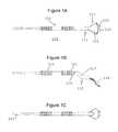
- FIG. 1 ais a bottom elevation view of a combination tongue and flap retractor with an S-shaped bend in accordance with an embodiment of the present invention
- FIG. 1 bis a side elevation view of the combination retractor shown in FIG. 1 a;
- FIG. 1 cis a top view of the combination retractor shown in FIG. 1 a;
- FIG. 1 dis a perspective view of the combination retractor shown in FIG. 1 a;
- FIG. 1 eis a top plan view of the operational unit of the combination retractor shown in FIG. 1 a;
- FIG. 1 fis a bottom plan view of the operational unit of the combination retractor shown in FIG. 1 a;
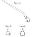
- FIG. 2 ais a bottom elevation view of a combination tongue and flap retractor with an S-shaped bend, where the flap retractor is at a reduced angle with respect to the handle axis and a more sharply curved tongue retractor in accordance with an embodiment of the present invention
- FIG. 2 bis a side elevation view of the combination retractor shown in FIG. 2 a;
- FIG. 2 cis a top view of the combination retractor shown in FIG. 2 a;
- FIG. 2 dis a perspective view of the combination retractor shown in FIG. 2 a;
- FIG. 2 eis a top plan view of the operational unit of the combination retractor shown in FIG. 2 a;
- FIG. 2 fis a bottom plan view of the operational unit of the combination retractor shown in FIG. 2 a;
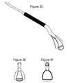
- FIG. 3 ais a bottom elevation view of a combination tongue and flap retractor with an S-shaped bend where the flap retractor is at a greater angle with respect to the handle axis, and a concave tongue retractor in accordance with an embodiment of the present invention
- FIG. 3 bis a side elevation view of the combination retractor shown in FIG. 3 a;
- FIG. 3 cis a top view of the retractor shown in FIG. 3 a;
- FIG. 3 dis a perspective view of the combination retractor shown in FIG. 3 a;
- FIG. 3 eis a top plan view of the operational unit of the combination retractor shown in FIG. 3 a;
- FIG. 3 fis a bottom plan view of the operational unit of the combination retractor shown in FIG. 3 a;
- FIG. 4 ais a bottom elevation view of a combination tongue and flap retractor with the tongue and flap retractor disposed on the same plane, with an S-shaped bend, and a short flap retractor in accordance with an embodiment of the present invention
- FIG. 4 bis a side elevation view of the combination retractor shown in FIG. 4 a;
- FIG. 4 cis a top view of the combination retractor shown in FIG. 4 a;
- FIG. 4 dis a perspective view of the combination retractor shown in FIG. 4 a;
- FIG. 4 eis a top plan view of the operational unit of the combination retractor shown in FIG. 4 a;
- FIG. 4 fis a bottom plan view of the operational unit of the combination retractor shown in FIG. 4 a;
- FIG. 5 ais a bottom elevation view of a combination tongue and flap retractor with an S-shaped bend, and a thickened tongue and flap retractor both formed as a continuous planar extension in accordance with an embodiment of the present invention
- FIG. 5 bis a side elevation view of the combination retractor shown in FIG. 5 a;
- FIG. 5 cis a top view of the combination retractor shown in FIG. 5 a;
- FIG. 5 dis a perspective view of the combination retractor shown in FIG. 5 a;
- FIG. 5 eis a top plan view of the operational unit of the combination retractor shown in FIG. 5 a;
- FIG. 5 fis a bottom plan view of the operational unit of the combination retractor shown in FIG. 5 a;
- FIG. 6 ais a bottom elevation view of a combination tongue and flap retractor with an S-shaped bend, and a small, thin tongue and flap retractor both formed as a continuous planar extension in accordance with an embodiment of the present invention
- FIG. 6 bis a side elevation view of the combination retractor shown in FIG. 6 a;
- FIG. 6 cis a top view of the combination retractor shown in FIG. 6 a;
- FIG. 6 dis a perspective view of the combination retractor shown in FIG. 6 a;
- FIG. 6 eis a top plan view of the operational unit of the combination retractor shown in FIG. 6 a;
- FIG. 6 fis a bottom plan view of the operational unit of the combination retractor shown in FIG. 6 a;
- FIG. 7 ais a bottom elevation view of a combination tongue and flap retractor with an S-shaped bend, bent to the left and thickened tongue and flap retractor both formed as a continuous planar extension in accordance with an embodiment of the present invention
- FIG. 7 bis a side elevation view of the combination retractor shown in FIG. 7 a;
- FIG. 7 cis a top view of the combination retractor shown in FIG. 7 a;
- FIG. 7 dis a perspective view of the combination retractor shown in FIG. 7 a;
- FIG. 7 eis a top plan view of the operational unit of the combination retractor shown in FIG. 7 a;
- FIG. 7 fis a bottom plan view of the operational unit of the combination retractor shown in FIG. 7 a;
- FIG. 8 ais a bottom elevation view of a concave tongue retractor with an S-shaped bend in accordance with an embodiment of the present invention
- FIG. 8 bis a side elevation view of the combination retractor shown in FIG. 8 a;
- FIG. 8 cis a top view of the combination retractor shown in FIG. 8 a;
- FIG. 8 dis a perspective view of the combination retractor shown in FIG. 8 a;
- FIG. 8 eis a top plan view of the operational unit of the combination retractor shown in FIG. 8 a;
- FIG. 8 fis a bottom plan view of the operational unit of the combination retractor shown in FIG. 8 a;
- FIG. 9 ais a bottom elevation view of a more sharply curved concave tongue retractor with an S-shaped bend in accordance with an embodiment of the present invention.
- FIG. 9 bis a side elevation view of the combination retractor shown in FIG. 9 a;
- FIG. 9 cis a top view of the combination retractor shown in FIG. 9 a;
- FIG. 9 dis a perspective view of the combination retractor shown in FIG. 9 a;
- FIG. 9 eis a top plan view of the operational unit of the combination retractor shown in FIG. 9 a;
- FIG. 9 fis a bottom plan view of the operational unit of the combination retractor shown in FIG. 9 a;
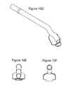
- FIG. 10 ais a bottom elevation view of a combination concave tongue and flap retractor with an S-shaped bend and a high speed suction device in accordance with an embodiment of the present invention
- FIG. 10 bis a side elevation view of the combination retractor shown in FIG. 10 a;
- FIG. 10 cis a top view of the combination retractor shown in FIG. 10 a;
- FIG. 10 dis a perspective view of the combination retractor shown in FIG. 10 a;
- FIG. 10 eis a top plan view of the operational unit of the combination retractor shown in FIG. 10 a;
- FIG. 10 fis a bottom plan view of the operational unit of the combination retractor shown in FIG. 10 a;
- FIG. 1 ashows a combination tongue and flap retractor 110 according to one embodiment of the present invention.
- the combination retractor 110may be formed of stainless steel, carbide, plastic or resin, or any other alloy or combination as is known in the art, and may include an operational unit 111 , a neck region 115 and a handle region 120 . Furthermore, the combination retractor may also be disposable.
- the combination tongue and flap retractormay be formed so as to be hollow or solid in construction. Additionally, the retractor may be partially hollow and/or partially solid in construction, i.e., some portions of the retractor may be hollow and some portions may be solid. Additionally, the cross section of the various portions of the combination tongue and flap retractor may be in different shapes. For example, the retractor may be round in cross section, or it could be faceted, such as for example a six-sided hexagon, an eight-sided octagon, and the like. Additionally, portions of the retractor may have different cross sections. For example, one portion of the retractor may be round in cross section, while another portion of the retractor may be faceted.
- the operational unit 111may further include a flap retractor 112 at the distal end of the instrument.
- This flap retractor 112preferably has a beveled edge 113 , which allows the flap retractor 112 to more easily hold the flap away from the treatment area.
- the operational unit 111may further contain a concave tongue retractor 114 for retracting the tongue away from the treatment area where the Dentist is working.
- the concave tongue retractor 114is used to retract and/or isolate the tongue during a procedure.
- the tongue retractor 114differs from conventional instruments in terms of functional shape and size. As can be appreciated from FIG. 1 b , the concave tongue retractor 114 is preferably shaped to provide for a natural area to encapsulate the tongue, thereby removing it from the treatment area.
- the design of the flap retractor 112makes it useful for reflecting a soft tissue flap (the gingival and/or gingival mucosa that has been raised as a surgical flap on the lingual aspect of the mandible).
- the combination retractor 110may be used to perform both functions at once or perform each function, e.g., tongue retraction and flap retraction, either simultaneously or separately depending on the Dentist's need. Combining these functions into a single device eliminates the need for two separate devices in the oral cavity during procedures, frees up a hand of the Dentist for other potential uses or eliminates the need to have an assistant's hand in the treatment area, and shortens the time of operation.
- the present inventionprovides improved ergonomics through the use of S-shapes and bends, which allow the instruments to be used on different sides of the mandible. These ergonomic features can be optionally incorporated into each of the devices discussed herein.
- the neck region 115may contain an S-shape bend 117 .
- the S-shapeallows the device to align more optimally in the oral cavity, such that a greatly reduced amount of downward and/or lateral force is needed to effect the desired tongue or flap retraction as compared to conventional instruments. This dramatically decreases the Dentist's fatigue and discomfort, and avoids prolonged strain on the neck, shoulder, back, and hand, thus reducing the risk of injury to the Dentist.
- the neck region 115 of the combination tongue and flap retractor of the present inventionmay further include a thread 119 for connecting the retractor to the handle 120 .
- the thread 119located at the end of the neck region 115 , serves to connect the neck region to the handle region 120 .
- any other method used in the artmay be used for connecting the two places.
- the combination tongue and flap retractormay also be formed as a unitary, one-piece implement in which case threads or other attachment mechanisms would not be needed.
- the handle 120may include grip portions 121 and 122 . These grip portions provide the practitioner with a comfortable, yet sure grip as he manipulates the instrument.
- the grip portions 121 and 122may be located at various positions along the handle 120 as desired for a comfortable grip. Further, the grip portions may be discrete, separate grip portions, or alternatively, a single grip portion may be provided on the retractor.
- the grip portions 121 and 122may be constructed with an embossed pattern. This embossing may be in the form of ribs, raised dots, or the like, or may also be constructed of a separate grip mat made of plastic, rubber or any other suitable material. As shown in FIG.
- the proximal end of the handlemay optionally include another dental instrument, such as a periosteal elevator 123 .
- another dental instrumentsuch as a periosteal elevator 123
- the proximal end of the handle 120may instead include a dental probe, a dental hook, or other useful apparatus.
- the tongue portion of the combination retractormay be longer and more sharply curved, i.e., having a curved profile.
- This embodimentshown in FIGS. 2 a - 2 f , has a tongue retractor 214 with an increased concavity (see FIG. 2 b ) for better encapsulation of the tongue and/or better accommodation of patients with larger tongues.
- the concave tongue and flap retractor 210may be formed by sharply curving the distal portion of the tongue retractor 214 , such that when viewed from the side, the tongue retractor 214 is substantially nonlinear and curved in profile.
- FIG. 3 ashows another embodiment 310 in which the tongue retractor 314 may be located on a different plane than the flap retractor.
- the angle of the flap retractormay be varied with respect to the central axis of the handle. While the flap retractor 212 of FIG. 2 b is disposed at a relatively shallow angle with respect to the central axis of the handle, the flap retractor 312 of FIG. 3 b is disposed at a steeper angle. In general, this angle may range from zero degrees to almost 90 degrees.
- the tongue retractormay also have the flap retractor positioned in generally the same plane as the tongue retractor.
- the concave tongue retractor and the flap retractorare integrated into a single instrument, a combination tongue and flap retractor.
- the flap retractoris in the form of a tapered, extended edge or tab, which can be made in various lengths.
- FIG. 4 aillustrates a concave tongue and flap retractor 410 , similar to that of FIG. 1 a , except that it includes a shortened flap retractor 412 as compared to flap retractor 112 .
- the shortened flap retractor 412may be useful when the flap being manipulated is not a large one.
- Yet another embodiment of the present inventionis directed to an integrated non-concave tongue and flap retractor as shown in FIG. 5 a .
- This combination tongue and flap retractorprovides the same advantages as the combination tongue and flap retractor of the previous embodiments discussed above, but provides yet another option for the Dentist.
- the flap and tongue retractor 510is provided with a greater thickness 514 relative to standard dental instruments, and is intended to be inserted into the oral cavity where the flap refraction is provided by a tapered leading edge 512 of the retractor 514 .
- This devicealso incorporates specifically rounded corners 514 a to better fit into the rounded shape of the mandible.
- the increased thickness portion 514may be as little as a few tenths of a millimeter in thickness to several millimeters or more.
- the thicknesscan be at least 0.5 millimeters.
- the integrated non-concave tongue and flap refractor 510also includes the S-shaped bend 517 in the neck region 515 for better ergonomics and advantages as described herein.
- the integrated non-concave tongue and flap retractormay be formed in various sizes.
- FIG. 6 ashows an integrated retractor 610 , similar to that of FIG. 5 a but smaller in size. Similar to the embodiment of FIG. 5 a , the integrated retractor includes rounded corners 614 a to better fit in the mandible and also includes the S-shaped bend 617 in the neck region 615 for better ergonomics and advantages as described herein.
- the integrated retractor 610also includes a greater thickness 614 and a tapered leading edge 612 similar to that of FIG. 5 a .
- the increased thickness portion 614may be as little as a few tenths of a millimeter in thickness to several millimeters of more.
- the neck regionmay also include a lateral bend positioned at the proximal end of the operational unit, so as to position the operational unit either to the right or the left with respect to the central axis of the handle.
- the combination tongue and flap retractor 710includes a bend 716 , which may be useful in navigating the instrument on one particular side of the mandible.
- This design featureallows the Dentist to utilize the instrument in a dramatically less awkward fashion.
- this designallows the Dentist to reduce or eliminate the need for twisting or turning their torso, upper extremities, and head and neck in an effort to use the instrument.
- This embodimentalso includes the S-shaped bend 717 in the neck region 715 for better ergonomics and advantages as described herein.
- FIG. 8 ashows a straight concave tongue retractor 810 with a concave design 814 for tongue encapsulation without a flap retractor.
- the straight concave tongue retractor 810also includes the S-shaped bend 817 in the neck region 815 for better ergonomics and advantages as described herein.
- FIG. 9 ashows a concave tongue retractor 910 similar to the straight concave tongue retractor 810 , but with a longer, and more sharply curved tongue retractor 914 for better encapsulation of the tongue.
- the concave tongue retractor 910may be formed by sharply curving the distal portion of the tongue retractor 914 .
- a high speed suction devicemay be incorporated in conjunction with any of the instruments disclosed herein.
- a high speed suction device 1010includes many of the features described above.
- the suction device 1010includes a tongue retractor 1014 , and a flap retractor 1012 , as well as an S-shaped bend 1017 .
- the suction device 1010includes a suction shaft 1030 for eliminating fluids such as saliva, water, and blood from the oral cavity.
- the suction shaftmay be in the form of a tube, duct or otherwise hollow body capable of eliminating fluids from the area of operation.
Landscapes
- Health & Medical Sciences (AREA)
- Life Sciences & Earth Sciences (AREA)
- Animal Behavior & Ethology (AREA)
- Veterinary Medicine (AREA)
- Public Health (AREA)
- General Health & Medical Sciences (AREA)
- Heart & Thoracic Surgery (AREA)
- Surgery (AREA)
- Molecular Biology (AREA)
- Medical Informatics (AREA)
- Biomedical Technology (AREA)
- Engineering & Computer Science (AREA)
- Oral & Maxillofacial Surgery (AREA)
- Dentistry (AREA)
- Epidemiology (AREA)
- Dental Tools And Instruments Or Auxiliary Dental Instruments (AREA)
Abstract
Description
Claims (17)
Priority Applications (5)
| Application Number | Priority Date | Filing Date | Title |
|---|---|---|---|
| US12/405,751US8297972B2 (en) | 2009-03-17 | 2009-03-17 | Combination tongue and flap retractor |
| US13/624,257US9198738B2 (en) | 2009-03-17 | 2012-09-21 | Combination tongue and flap retractor |
| US13/927,560US10813718B2 (en) | 2009-03-17 | 2013-06-26 | Ergonomic dental tools |
| US14/989,473US20160135921A1 (en) | 2009-03-17 | 2016-01-06 | Ergonomic dental tools |
| US17/080,159US12440195B2 (en) | 2020-10-26 | Combination ergonomic suction tool |
Applications Claiming Priority (1)
| Application Number | Priority Date | Filing Date | Title |
|---|---|---|---|
| US12/405,751US8297972B2 (en) | 2009-03-17 | 2009-03-17 | Combination tongue and flap retractor |
Related Child Applications (1)
| Application Number | Title | Priority Date | Filing Date |
|---|---|---|---|
| US13/624,257ContinuationUS9198738B2 (en) | 2009-03-17 | 2012-09-21 | Combination tongue and flap retractor |
Publications (2)
| Publication Number | Publication Date |
|---|---|
| US20100240005A1 US20100240005A1 (en) | 2010-09-23 |
| US8297972B2true US8297972B2 (en) | 2012-10-30 |
Family
ID=42737968
Family Applications (2)
| Application Number | Title | Priority Date | Filing Date |
|---|---|---|---|
| US12/405,751Active - Reinstated2030-09-04US8297972B2 (en) | 2009-03-17 | 2009-03-17 | Combination tongue and flap retractor |
| US13/624,257Active - ReinstatedUS9198738B2 (en) | 2009-03-17 | 2012-09-21 | Combination tongue and flap retractor |
Family Applications After (1)
| Application Number | Title | Priority Date | Filing Date |
|---|---|---|---|
| US13/624,257Active - ReinstatedUS9198738B2 (en) | 2009-03-17 | 2012-09-21 | Combination tongue and flap retractor |
Country Status (1)
| Country | Link |
|---|---|
| US (2) | US8297972B2 (en) |
Cited By (4)
| Publication number | Priority date | Publication date | Assignee | Title |
|---|---|---|---|---|
| US20120330368A1 (en)* | 2010-03-05 | 2012-12-27 | University Of Massachusetts | Zygomatic elevator device and methods |
| KR200472398Y1 (en) | 2012-06-07 | 2014-04-23 | 박현근 | Assistance apparatus for filler injections |
| US20180256292A1 (en)* | 2017-03-09 | 2018-09-13 | King Abdulaziz University | Dental tool for shaping dental restoration |
| US20210338397A1 (en)* | 2020-05-04 | 2021-11-04 | Stoma Ventures, LLC | Disposable dental aerosol device |
Families Citing this family (11)
| Publication number | Priority date | Publication date | Assignee | Title |
|---|---|---|---|---|
| US8297972B2 (en) | 2009-03-17 | 2012-10-30 | Manuel Barry Gordon | Combination tongue and flap retractor |
| US10813718B2 (en) | 2009-03-17 | 2020-10-27 | Manuel Barry Gordon | Ergonomic dental tools |
| USD668333S1 (en)* | 2011-02-01 | 2012-10-02 | B&L Biotech, Inc. | Oral retractor for dental purpose |
| USD718856S1 (en)* | 2013-04-24 | 2014-12-02 | Eric M. Altschuler | Suction cobb periosteal elevator |
| EP3013274A4 (en)* | 2013-06-26 | 2016-12-28 | Manuel Barry Gordon | Ergonomic dental tools |
| USD879959S1 (en)* | 2016-02-24 | 2020-03-31 | Hari Reyes | Rigid tongue retractor |
| US11426063B2 (en)* | 2016-05-09 | 2022-08-30 | Tzu-Li Hsu | Tongue anteriorizer |
| US11771412B2 (en)* | 2016-11-11 | 2023-10-03 | University Of Iowa Research Foundation | Eyelid flipper tool |
| TWM561513U (en)* | 2018-02-09 | 2018-06-11 | Wen Shih Cheng | Periosteum stripper with hook-shaped combing structure |
| US11883015B2 (en)* | 2018-09-23 | 2024-01-30 | Ning Miao Su | Retractor used to assist cuff implantation, tissue repositioning and other applications |
| DE102021123066A1 (en) | 2021-09-07 | 2023-03-09 | Iman Mizani | Retractors for use in dental procedures |
Citations (14)
| Publication number | Priority date | Publication date | Assignee | Title |
|---|---|---|---|---|
| US1465259A (en)* | 1921-10-10 | 1923-08-21 | Friedman Henry | Dental apparatus |
| US1497749A (en)* | 1922-05-10 | 1924-06-17 | Alexander S Diack | Dental tool |
| US2603870A (en)* | 1950-09-07 | 1952-07-22 | Nordin Elling Harald | Saliva ejector |
| US3090122A (en)* | 1961-01-18 | 1963-05-21 | Norman R Erickson | Dental appliance |
| US4270902A (en)* | 1978-12-18 | 1981-06-02 | Lawrence Wiland | Method and apparatus for carving and contouring dental restorations |
| US4883426A (en)* | 1987-12-03 | 1989-11-28 | Ferrer Euler R | Dental implement for fluid aspiration and tissue retraction |
| US5078602A (en)* | 1990-04-30 | 1992-01-07 | Geraldine Honoshofsky | Saliva ejector and method for cleaning the same |
| US5846192A (en)* | 1997-10-31 | 1998-12-08 | Teixido-Longworth Partnership | Polymeric surgical retractor |
| US6174162B1 (en)* | 1999-12-27 | 2001-01-16 | American Tooth Industries | Instrument for adjusting orthodontic expander |
| US6241658B1 (en)* | 2000-07-12 | 2001-06-05 | Harriet T. Goodrich | Suction retractor |
| US20020128673A1 (en)* | 2001-01-04 | 2002-09-12 | Ripich Robert J. | Tongue cleaning device |
| US6575749B1 (en)* | 2002-04-11 | 2003-06-10 | Paul D. Greenwald | Gingival retractor |
| US20050228233A1 (en)* | 2000-09-29 | 2005-10-13 | Stephen Ritland | Method and device for microsurgical intermuscular spinal surgery |
| US7238023B1 (en)* | 2004-12-14 | 2007-07-03 | Enos Denise A | Saliva ejector or eductor |
Family Cites Families (17)
| Publication number | Priority date | Publication date | Assignee | Title |
|---|---|---|---|---|
| US637970A (en)* | 1897-12-27 | 1899-11-28 | John Egbert Nyman | Dental saliva-ejector and tongue-depressor. |
| US1009551A (en) | 1911-01-03 | 1911-11-21 | Guy J Nations | Dental appliance. |
| US2723661A (en)* | 1954-05-20 | 1955-11-15 | Oval Wood Dish Corp | Tongue depressor |
| US2831480A (en) | 1956-10-31 | 1958-04-22 | Milano Francis | Cheek and tongue retractor |
| FR2159635A5 (en)* | 1971-11-05 | 1973-06-22 | Bouffard Pierre | |
| USD291001S (en)* | 1985-11-22 | 1987-07-21 | Jean Gaskins | Tongue scraper |
| US5730597A (en) | 1996-06-05 | 1998-03-24 | The United States Of America As Represented By The Secretary Of The Navy | Lip and cheek retractor |
| US5816806A (en) | 1996-07-31 | 1998-10-06 | Hu-Friedy Mfg. Co., Inc. | Dental instruments with large molded handles |
| USD391370S (en)* | 1997-07-02 | 1998-02-24 | Cho Spencer Y | Plastic tongue scraper having a concave collecting head |
| US6045499A (en)* | 1998-10-27 | 2000-04-04 | Pitesky; Isadore | Tongue retractor |
| US6632095B2 (en)* | 2000-03-01 | 2003-10-14 | Bruce P. Ryan | Tongue lifter |
| US6837707B2 (en) | 2002-10-30 | 2005-01-04 | Josefina Figueredo Torres | Double dental mirror |
| USD509590S1 (en)* | 2003-10-15 | 2005-09-13 | Spencer Y. Cho | Tongue cleaner with pivotably foldable handle |
| US20050197665A1 (en)* | 2004-03-08 | 2005-09-08 | Teed Ralph A. | Tongue cleaners |
| CN201091589Y (en)* | 2007-10-25 | 2008-07-30 | 何彩英 | Dual-purpose tongue depressor |
| US20100021863A1 (en)* | 2008-07-23 | 2010-01-28 | Brad Braman | Dental Retractor |
| US8297972B2 (en) | 2009-03-17 | 2012-10-30 | Manuel Barry Gordon | Combination tongue and flap retractor |
- 2009
- 2009-03-17USUS12/405,751patent/US8297972B2/enactiveActive - Reinstated
- 2012
- 2012-09-21USUS13/624,257patent/US9198738B2/enactiveActive - Reinstated
Patent Citations (14)
| Publication number | Priority date | Publication date | Assignee | Title |
|---|---|---|---|---|
| US1465259A (en)* | 1921-10-10 | 1923-08-21 | Friedman Henry | Dental apparatus |
| US1497749A (en)* | 1922-05-10 | 1924-06-17 | Alexander S Diack | Dental tool |
| US2603870A (en)* | 1950-09-07 | 1952-07-22 | Nordin Elling Harald | Saliva ejector |
| US3090122A (en)* | 1961-01-18 | 1963-05-21 | Norman R Erickson | Dental appliance |
| US4270902A (en)* | 1978-12-18 | 1981-06-02 | Lawrence Wiland | Method and apparatus for carving and contouring dental restorations |
| US4883426A (en)* | 1987-12-03 | 1989-11-28 | Ferrer Euler R | Dental implement for fluid aspiration and tissue retraction |
| US5078602A (en)* | 1990-04-30 | 1992-01-07 | Geraldine Honoshofsky | Saliva ejector and method for cleaning the same |
| US5846192A (en)* | 1997-10-31 | 1998-12-08 | Teixido-Longworth Partnership | Polymeric surgical retractor |
| US6174162B1 (en)* | 1999-12-27 | 2001-01-16 | American Tooth Industries | Instrument for adjusting orthodontic expander |
| US6241658B1 (en)* | 2000-07-12 | 2001-06-05 | Harriet T. Goodrich | Suction retractor |
| US20050228233A1 (en)* | 2000-09-29 | 2005-10-13 | Stephen Ritland | Method and device for microsurgical intermuscular spinal surgery |
| US20020128673A1 (en)* | 2001-01-04 | 2002-09-12 | Ripich Robert J. | Tongue cleaning device |
| US6575749B1 (en)* | 2002-04-11 | 2003-06-10 | Paul D. Greenwald | Gingival retractor |
| US7238023B1 (en)* | 2004-12-14 | 2007-07-03 | Enos Denise A | Saliva ejector or eductor |
Non-Patent Citations (2)
| Title |
|---|
| Instruments-Miscellaneous, Knives/Spatulas/Retractors, Sullivan-Schein Dental Supply Catalog, 2007, p. 584. |
| Instruments-Retractors, Misch Spoon and Minesota Retractor, Salvin Dental Supply Catalog, 2011, p. 114. |
Cited By (8)
| Publication number | Priority date | Publication date | Assignee | Title |
|---|---|---|---|---|
| US20120330368A1 (en)* | 2010-03-05 | 2012-12-27 | University Of Massachusetts | Zygomatic elevator device and methods |
| US10245093B2 (en)* | 2010-03-05 | 2019-04-02 | University Of Massachusetts | Zygomatic elevator device and methods |
| US11607259B2 (en) | 2010-03-05 | 2023-03-21 | University Of Massachusetts | Zygomatic elevator device and methods |
| KR200472398Y1 (en) | 2012-06-07 | 2014-04-23 | 박현근 | Assistance apparatus for filler injections |
| US20180256292A1 (en)* | 2017-03-09 | 2018-09-13 | King Abdulaziz University | Dental tool for shaping dental restoration |
| US10420627B2 (en)* | 2017-03-09 | 2019-09-24 | King Abdulaziz University | Dental tool for shaping dental restoration |
| US20210338397A1 (en)* | 2020-05-04 | 2021-11-04 | Stoma Ventures, LLC | Disposable dental aerosol device |
| US12226273B2 (en)* | 2020-05-04 | 2025-02-18 | Stoma Ventures, LLC | Disposable dental aerosol device |
Also Published As
| Publication number | Publication date |
|---|---|
| US20100240005A1 (en) | 2010-09-23 |
| US9198738B2 (en) | 2015-12-01 |
| US20130017509A1 (en) | 2013-01-17 |
Similar Documents
| Publication | Publication Date | Title |
|---|---|---|
| US8297972B2 (en) | Combination tongue and flap retractor | |
| US10813718B2 (en) | Ergonomic dental tools | |
| US7249948B2 (en) | Ergonomic dental instruments for small hands | |
| US6102701A (en) | Retractor apparatus | |
| JP6262650B2 (en) | Equipment related to oral and dental care | |
| US5730597A (en) | Lip and cheek retractor | |
| US20160270878A1 (en) | Dental device and suction device | |
| US20100240008A1 (en) | Forceps for molar extraction | |
| CN108472107B (en) | Dental retractor | |
| WO2014209504A9 (en) | Ergonomic dental tools | |
| EP4527345A1 (en) | Ergonomic dental elevator | |
| US20030186193A1 (en) | Hand-held medical/dental tool | |
| US8784101B1 (en) | Retractor apparatus | |
| CN216823707U (en) | Shell-shaped appliance with interdental bridge | |
| US12440195B2 (en) | Combination ergonomic suction tool | |
| US20190038379A1 (en) | Dental retractor | |
| CN216933574U (en) | Special operation draw hook of alveolar surgery | |
| US20210346125A1 (en) | Combination Ergonomic Suction Tool | |
| EP2243440A1 (en) | Hand instrument for manual dental care | |
| US20200046457A1 (en) | Interim Provisional Restoration Placement Instrument-#1 | |
| CN221357223U (en) | Mirror oral retractor | |
| KR101924578B1 (en) | dental retractor | |
| US20200046456A1 (en) | Interim therapeutic restoration and cavity liner placement (itr) instrument description | |
| CN209827063U (en) | Left-bent 115-degree magnetostrictive working tip | |
| CN209808608U (en) | Right-bent 115-degree magnetostrictive working tip |
Legal Events
| Date | Code | Title | Description |
|---|---|---|---|
| AS | Assignment | Owner name:GORDON, MANUEL BARRY, NEW YORK Free format text:ASSIGNMENT OF ASSIGNORS INTEREST;ASSIGNORS:GORDON, MATTHEW;GORDON, MANUEL BARRY;REEL/FRAME:024582/0090 Effective date:20100610 | |
| ZAAA | Notice of allowance and fees due | Free format text:ORIGINAL CODE: NOA | |
| ZAAB | Notice of allowance mailed | Free format text:ORIGINAL CODE: MN/=. | |
| STCF | Information on status: patent grant | Free format text:PATENTED CASE | |
| FPAY | Fee payment | Year of fee payment:4 | |
| FEPP | Fee payment procedure | Free format text:MAINTENANCE FEE REMINDER MAILED (ORIGINAL EVENT CODE: REM.); ENTITY STATUS OF PATENT OWNER: SMALL ENTITY | |
| LAPS | Lapse for failure to pay maintenance fees | Free format text:PATENT EXPIRED FOR FAILURE TO PAY MAINTENANCE FEES (ORIGINAL EVENT CODE: EXP.); ENTITY STATUS OF PATENT OWNER: SMALL ENTITY | |
| STCH | Information on status: patent discontinuation | Free format text:PATENT EXPIRED DUE TO NONPAYMENT OF MAINTENANCE FEES UNDER 37 CFR 1.362 | |
| FP | Lapsed due to failure to pay maintenance fee | Effective date:20201030 | |
| FEPP | Fee payment procedure | Free format text:PETITION RELATED TO MAINTENANCE FEES FILED (ORIGINAL EVENT CODE: PMFP); ENTITY STATUS OF PATENT OWNER: SMALL ENTITY | |
| FEPP | Fee payment procedure | Free format text:SURCHARGE, PETITION TO ACCEPT PYMT AFTER EXP, UNINTENTIONAL. (ORIGINAL EVENT CODE: M2558); ENTITY STATUS OF PATENT OWNER: SMALL ENTITY | |
| MAFP | Maintenance fee payment | Free format text:PAYMENT OF MAINTENANCE FEE, 8TH YR, SMALL ENTITY (ORIGINAL EVENT CODE: M2552); ENTITY STATUS OF PATENT OWNER: SMALL ENTITY Year of fee payment:8 | |
| FEPP | Fee payment procedure | Free format text:PETITION RELATED TO MAINTENANCE FEES GRANTED (ORIGINAL EVENT CODE: PTGR); ENTITY STATUS OF PATENT OWNER: SMALL ENTITY Free format text:PETITION RELATED TO MAINTENANCE FEES DISMISSED (ORIGINAL EVENT CODE: PMFS); ENTITY STATUS OF PATENT OWNER: SMALL ENTITY | |
| FEPP | Fee payment procedure | Free format text:PETITION RELATED TO MAINTENANCE FEES FILED (ORIGINAL EVENT CODE: PMFP); ENTITY STATUS OF PATENT OWNER: SMALL ENTITY | |
| FEPP | Fee payment procedure | Free format text:PETITION RELATED TO MAINTENANCE FEES DISMISSED (ORIGINAL EVENT CODE: PMFS); ENTITY STATUS OF PATENT OWNER: SMALL ENTITY | |
| FEPP | Fee payment procedure | Free format text:PETITION RELATED TO MAINTENANCE FEES FILED (ORIGINAL EVENT CODE: PMFP); ENTITY STATUS OF PATENT OWNER: SMALL ENTITY | |
| PRDP | Patent reinstated due to the acceptance of a late maintenance fee | Effective date:20240213 | |
| FEPP | Fee payment procedure | Free format text:PETITION RELATED TO MAINTENANCE FEES GRANTED (ORIGINAL EVENT CODE: PMFG); ENTITY STATUS OF PATENT OWNER: SMALL ENTITY | |
| STCF | Information on status: patent grant | Free format text:PATENTED CASE | |
| FEPP | Fee payment procedure | Free format text:11.5 YR SURCHARGE- LATE PMT W/IN 6 MO, SMALL ENTITY (ORIGINAL EVENT CODE: M2556); ENTITY STATUS OF PATENT OWNER: SMALL ENTITY | |
| MAFP | Maintenance fee payment | Free format text:PAYMENT OF MAINTENANCE FEE, 12TH YR, SMALL ENTITY (ORIGINAL EVENT CODE: M2553); ENTITY STATUS OF PATENT OWNER: SMALL ENTITY Year of fee payment:12 |