US8297869B2 - Packaging and applicator device - Google Patents
Packaging and applicator deviceDownload PDFInfo
- Publication number
- US8297869B2 US8297869B2US11/730,516US73051607AUS8297869B2US 8297869 B2US8297869 B2US 8297869B2US 73051607 AUS73051607 AUS 73051607AUS 8297869 B2US8297869 B2US 8297869B2
- Authority
- US
- United States
- Prior art keywords
- reservoir
- application face
- cavity
- composition
- applicator
- Prior art date
- Legal status (The legal status is an assumption and is not a legal conclusion. Google has not performed a legal analysis and makes no representation as to the accuracy of the status listed.)
- Expired - Fee Related, expires
Links
Images


Classifications
- A—HUMAN NECESSITIES
- A45—HAND OR TRAVELLING ARTICLES
- A45D—HAIRDRESSING OR SHAVING EQUIPMENT; EQUIPMENT FOR COSMETICS OR COSMETIC TREATMENTS, e.g. FOR MANICURING OR PEDICURING
- A45D34/00—Containers or accessories specially adapted for handling liquid toiletry or cosmetic substances, e.g. perfumes
- A45D34/04—Appliances specially adapted for applying liquid, e.g. using roller or ball
- A—HUMAN NECESSITIES
- A45—HAND OR TRAVELLING ARTICLES
- A45D—HAIRDRESSING OR SHAVING EQUIPMENT; EQUIPMENT FOR COSMETICS OR COSMETIC TREATMENTS, e.g. FOR MANICURING OR PEDICURING
- A45D2200/00—Details not otherwise provided for in A45D
- A45D2200/05—Details of containers
- A45D2200/054—Means for supplying liquid to the outlet of the container
- A45D2200/055—Piston or plunger for supplying the liquid to the applicator
- A—HUMAN NECESSITIES
- A45—HAND OR TRAVELLING ARTICLES
- A45D—HAIRDRESSING OR SHAVING EQUIPMENT; EQUIPMENT FOR COSMETICS OR COSMETIC TREATMENTS, e.g. FOR MANICURING OR PEDICURING
- A45D2200/00—Details not otherwise provided for in A45D
- A45D2200/10—Details of applicators
- A45D2200/1009—Applicators comprising a pad, tissue, sponge, or the like
- A45D2200/1018—Applicators comprising a pad, tissue, sponge, or the like comprising a pad, i.e. a cushion-like mass of soft material, with or without gripping means
Definitions
- the present inventionrelates to packaging and applicator devices comprising a reservoir containing at least one composition to be dispensed, and an applicator element that is secured to the reservoir at least during application.
- U.S. Pat. No. 6,745,781describes a device of that type, in which the applicator element includes a flocked mesh.
- U.S. Pat. No. 6,688,317describes a device in which the applicator element includes a groove that makes it possible to collect excess composition that is present on the application face.
- international application WO 02/085733discloses a device including a support and a compressible applicator element that is mounted in stationary manner on a face of the support.
- An annular grooveis formed between the support and the face of the applicator element that faces said support, so as to impart increased flexibility to the peripheral region of the applicator element.
- the compositioncan accumulate on the periphery of the applicator element, which can lead to makeup not being applied as uniformly as desired, in particular with highly colored compositions having an appearance that is very dependent on the quality of the deposit formed on the lips.
- the inventionseeks to satisfy all or some of those needs.
- a packaging and applicator device for applying at least one cosmetic composition, including a care productcomprising:
- the applicator headpresents both flexibility and capacity to change, in relatively even manner, the region to which composition is to be applied.
- the cavitymakes it possible to build up a supply of composition, and it can also serve to collect the composition.
- the cavitymakes it possible to smooth out the layer of composition deposited during application.
- the cantilevered-out portionmay be obtained by a flexible portion of the applicator head and by the reservoir being configured in such a manner that the flexibility of said flexible portion makes it possible to change the orientation of at least a portion of the application face when said application face is subjected to stress, in particular when it is brought manually against a surface to be made-up, in particular the lips.
- the flexible portionmay advantageously be formed in the proximity of the reservoir, set back from a free distal end of the application face.
- the portion of the application face of orientation that may be changedmay be disposed facing a part of the reservoir that presents a step or a slope that, when said portion is at rest, is less than the slope of said portion relative to the longitudinal axis of the reservoir.
- the cavitymay be distinct from a capillary slot, having a diameter lying in the range 1 millimeter (mm) to 5 mm, for example, and preferably of about 3 mm.
- the cavitymay be oval.
- the applicator headmay make it possible to deposit a plurality of layers of composition, so as to increase the glossiness of the lips, for example.
- the applicator headmay optionally be flocked.
- the flockingmay advantageously be made with bristles of length that is greater than 1 mm, e.g. a length of 1.2 mm, such that the ends of the flocking bristles define a plane that is distinct from a plane in which the cavity is defined.
- the bristlesWhen the applicator head is flocked, the bristles may be substantially identical, or different and mixed.
- the cantilevered-out portionmay advantageously be flexible.
- the cantilevered-out portionmay define the entire periphery of the application face.
- the applicator elementmay include a thin zone at the base of the cantilevered-out portion, thereby enabling said portion to flex more easily.
- the applicator elementmay include a fastening endpiece for fastening to the reservoir, the endpiece possibly having the feed channel passing therethrough.
- the endpiecemay optionally be relatively rigid, possibly being made in such a manner as to enable the applicator head to pivot about at least one axis, or even about at least two axes that are perpendicular to each other.
- the applicator elementmay be molded from at least two materials, one rigid and the other flexible. By way of example, the endpiece may be molded from the flexible material.
- the cavitymay be a through-cavity, and the feed channel may open out into the cavity.
- the cavitythat may enable a supply of composition to be accumulated, may be fed with composition via its end remote from the application face, or, in a variant, it may be fed with composition via a side orifice.
- the cavitymay advantageously not be centered relative to the application face.
- the reservoirmay include at least one extension that covers the applicator element at least in part.
- a gapmay be formed between the applicator element and the extension, said extension being substantially in contact with possible flocking of the applicator element, for example.
- the extensionmay cover the cavity at least in part.
- the application facemay present a tapering shape, in particular an upwardly-tapering shape. This may improve accuracy in applying makeup, in particular in applying makeup to the top lip.
- the application facemay present a pear-shaped outline.
- the application facemay be generally plane, or concave, or convex.
- the application facemay extend all around the axis of the reservoir.
- the application faceWhen at rest, the application face may lie in a plane. Said plane may be oriented obliquely relative to the reservoir, the acute angle formed between the longitudinal axis of the reservoir and the application face lying in the range 10° to 90°, for example, preferably in the range 25° to 65°, and better in the range 35° to 40°.
- the reservoirmay include a flexible wall.
- the reservoirmay also include a rigid cylindrical wall in which a piston may slide.
- compositionmay also be contained in a flexible pouch, with dispensing being performed without ingress of air.
- the above-mentioned endpiecemay be centered or off-center relative to the applicator head.
- the application facemay extend generally obliquely relative to a longitudinal axis of the reservoir.
- the applicator elementmay be made as a single part by molding an elastomer material.
- the applicator headmay be made of: silicone; nitrile rubber; ethylene-propylene terpolymer rubber (EPDM); polyurethane (PU); butyl rubber; latex; thermoplastic elastomer; styrene; ethylene; polyvinyl chloride (PVC); polyurethane (PU); ethyl vinyl acetate (EVA); ethylene-propylene terpolymer rubber (EPDM); etc.; styrene-ethylene-butylene-styrene (SEBS); or one of the elastomers known under the trade names CARIFLEX, SANTOPRENE, HYTREL, PEBAX (polyether block amide).
- the applicator headmay present magnetic properties, e.g. so as to impart a particular orientation to magnetic particles that are contained in the composition, or so as to change at least one property of the composition.
- the cavitymay open out into the application face via an opening that is of greater section than the opening of an orifice of the reservoir via which the composition contained in the reservoir reaches the cavity.
- the reservoirmay contain a composition for making-up the lips.
- composition contained in the reservoirmay be a paste or a gel, e.g. having viscosity such that it does not flow by capillarity when the device in which it is contained is head down.
- the devicemay include a closure member having a closure pin that is disposed in such a manner as to close an outlet orifice through which the composition is dispensed onto the application face.
- the pinis arranged to be engaged in the feed channel so as to close it, or it is arranged to bear against the applicator head all around the composition outlet orifice.
- the outlet orificemay present a greatest dimension that is greater than or equal to 2 mm, and said outlet orifice may be of any shape, in particular oval shaped.
- the inside section of the outlet orificemay present a greatest dimension, in particular a diameter, that is less than 5 mm, for example.
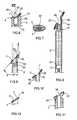
- FIG. 1is a diagrammatic elevation view of an example of a packaging and applicator device of the invention
- FIG. 2is a fragmentary longitudinal section of the FIG. 1 device
- FIG. 3is a diagrammatic view as seen looking along arrow III of FIG. 2 ;
- FIG. 4is a diagrammatic perspective view of the bottom end of the FIG. 1 reservoir body, with the piston control button removed;
- FIG. 5is a plan view of the piston control button
- FIG. 6is a view similar to FIG. 2 , showing a variant embodiment
- FIG. 7is a plan view as seen looking along arrow VII of FIG. 6 ;
- FIGS. 8 to 11 , 13 , 14 , 16 , and 17are fragmentary longitudinal sections of variant embodiments of the applicator
- FIGS. 12 and 15are fragmentary elevation views of variant embodiments
- FIG. 18is a view from below of the applicator element shown in isolation
- FIGS. 19 and 20are fragmentary perspective views of other examples of an applicator head
- FIGS. 21 and 22are diagrammatic and fragmentary longitudinal sections of variant embodiments of the device.
- FIGS. 23 to 27are front views of the applicator head, constituting other variant embodiments.
- FIG. 28is a fragmentary longitudinal section of a closure member
- FIGS. 29 to 31are fragmentary longitudinal sections in elevation of other variants.
- the packaging and applicator device 1 shown in FIGS. 1 to 5includes a reservoir 2 , of longitudinal axis X, containing the composition P for application, and possibly having a transparent portion 3 enabling the user to see the composition P.
- the composition Pis a paste or a gel, having viscosity such that it does not flow by capillarity when the device 1 is head down.
- the top portion of the reservoir 2can comprise a support 4 for an applicator element including an applicator head 5 defining an application face 7 for coming, at least in part, into contact with the region to be treated.
- At least one feed channel 10 for supplying composition to the application face 7passes through the support 4 .
- the composition Pmay be forced to flow through the feed channel 10 by means of a piston 12 that is in screw engagement on a threaded rod 13 , and that can move in translation in the reservoir 2 while the threaded rod 13 is being turned by means of a control button 15 situated in the bottom portion of the reservoir.
- the reservoir 2can present a tubular body of cross-section that is not circular, e.g. oval.
- the applicator head 5When not in use, the applicator head 5 may can be protected by a closure cap 16 that may be fastened on the reservoir 2 .
- the application face 7extends obliquely, being generally inclined, when at rest, by an angle ⁇ relative to the longitudinal axis X of the reservoir 2 , the angle ⁇ lying in the range 10° to 90°, for example, preferably in the range 25° to 65°, and still better in the range 35° to 40°.
- the control button 15may be turned by increments, the bottom portion of the reservoir 2 including a plurality of tabs 17 , for example, that are disposed around the rod 13 , and against which there can be applied two diametrally opposite brakes 18 of the control button 15 , as can be seen in FIG. 5 .
- the control buttonmay include a central splined cylinder 19 that is arranged to be engaged in a grooved housing 20 that is provided at the bottom end of the rod 13 , so as to transmit torque between the control button 15 and the rod 13 .
- the applicator head 5includes at least one cantilevered-out portion 25 .
- the cantilevered-out configuration of the portion 25is obtained by a flexible portion 21 of the applicator head 5 , and by the configuration of the support 4 .
- the portion 21presents flexibility that makes it possible, in use, to change the orientation of the portion 25 relative to the longitudinal axis X.
- the orientation of the portion 25is changed when said portion is subjected to stress, e.g. by being brought manually against a surface of the body to be made-up, e.g. the lips.
- the flexible portion 21is formed in the proximity of the reservoir 2 , and set back from a free distal end of the application face 7 .
- the portion 25extends over the support 4 , co-operating with said support to define a gap 26 enabling said portion 25 to flex, e.g. along arrow F in FIG. 2 , towards the support 4 .
- the portion 25extends over a part 22 of the support 4 that presents a step or a slope that, when said portion is at rest, is less than the slope of said portion 25 relative to the axis X, as shown in FIG. 30 .
- the width of the gap 26is a few tenths of a millimeter, or even a few millimeters.
- the cantilevered-out portion 25may define a fraction only of the periphery of the application face 7 , or it may define the entire periphery, as shown.
- the gap 26may present an annular shape that extends all around a hollow endpiece 30 of the applicator element, said hollow endpiece serving to mount the applicator head on the reservoir 2 , and communicating with the feed channel 10 for bringing the composition towards the application face 7 .
- the flexibility of the cantilevered-out portion 25may be linked to the choice of material that is used to make the applicator head and/or to the presence, on said applicator head, of at least one hinge-forming zone or a zone of weakness.
- the applicator head 5may be made integrally with the endpiece 30 by molding a material, in particular an elastomer material.
- the endpiecemay be fastened on the reservoir 2 in various ways, e.g. by snap-fastening, by force-fitting, by screw-fastening, by adhesive, or by heat-sealing.
- the applicator elementmay be made, at least in part, with the reservoir 2 , e.g. with the support 4 , by injection-molding or by dual injection.
- the endpiece 30opens out into a cavity 35 of the applicator head 5 that is open in the application face 7 .
- the cavity 35is a single cavity and is completely surrounded by the application face 7 .
- the cavity 35extends all around the axis of the reservoir and opens out into the application face 7 permanently without any valve.
- the applicator head 5is advantageously flocked at least over the application face 7 , in particular as can be seen in FIG. 3 .
- the applicator head 5may also be flocked over its periphery, or even also over the bottom face of the cantilevered-out portion 25 .
- the flockingis made with bristles of a length that is greater than 1 mm, e.g. equal to 1.2 mm, such that the ends of the flocking bristles define a plane that is distinct from the plane in which the cavity extends.
- the usermay turn the control button 15 in such a manner as to cause the piston 12 to rise and bring the composition P onto the application face 7 through the cavity 35 .
- composition Pmay be spread, on the lips in particular, in relatively uniform, accurate, and comfortable manner.
- the inside channel in the endpiece 30opens out into the cavity 35 through a mesh 40 that may slow down the flow of composition P.
- the applicator head 5may present a tapering shape, as can be seen in FIG. 3 , with a point 43 that is situated at the top end of the application face 7 , for example.
- FIGS. 8 to 27It can be seen in FIGS. 8 to 27 that various shapes may be given as much to the reservoir 2 as to the applicator element.
- the reservoir 2may include a neck 50 , and the endpiece 30 may be arranged to be fastened on the outside of the neck 50 .
- the applicator head 5may extend laterally beyond the reservoir 2 , when said reservoir is observed along the axis X, by a distance d that may be optionally constant around the axis X.
- the distance dis greater than or equal to 1 mm, indeed greater than or equal to 2 mm or 3 mm, or indeed even more.
- the endpiece 30may also be engaged in an annular groove 51 of the reservoir 2 , as shown in FIG. 9 , the neck 50 being surrounded by an outer skirt 54 that covers the outside of the endpiece 30 at least in part, for example.
- FIG. 10shows the possibility of forming, on the applicator head 5 , a hinge-forming zone 55 at the base of the cantilevered-out portion 25 , so as to increase its flexibility relative to the endpiece 30 .
- the hinge-forming zone 55may extend annularly around the endpiece 30 , e.g. being formed by a groove 56 present on the bottom face of the applicator head 5 .
- FIG. 11shows another embodiment in which the applicator element is fastened by snap-fastening on the reservoir 2 , and in which the outside surface of the endpiece 30 lies flush with the outside surface of the reservoir 2 .
- the applicator head 5may come into contact with the reservoir 2 , except for the cantilevered-out portion 25 that extends beyond the reservoir 2 , as shown in FIG. 12 .
- the periphery of the applicator head 5hardly projects beyond the reservoir 2 when said reservoir is observed along the axis X, and the endpiece 30 is received in an annular groove 58 of the reservoir 2 , which groove is radially defined by a tubular skirt 60 having a top that is situated at a certain distance from the bottom face of the cantilevered-out portion 25 .
- FIG. 14shows the possibility of making the applicator element with at least one sealing lip 65 that comes to be engaged on the reservoir 2 , so as to ensure that the applicator element is mounted in sealed manner on the reservoir 2 .
- the cantilevered-out portion 25may extend laterally on one side only of the reservoir 2 , as shown in FIG. 15 .
- FIG. 16shows an applicator head including a zone of weakness 55 , the dimensions of the cantilevered-out portion 25 nevertheless being different.
- FIG. 17shows the possibility of the cavity 35 presenting an outwardly-flaring shape, the inside of the cavity 35 possibly being flocked.
- the endpiece 30may optionally slope relative to the cantilevered-out portion 25 of the applicator head.
- endpiece 30may be connected to the applicator head in a central region of said applicator head or that it may be connected off-center.
- the endpiece 30may be sufficiently flexible for said applicator head to pivot about two axes A and B that are perpendicular to each other, and perpendicular to the axis C of the endpiece 30 .
- the cavity 35 that opens out into the application face 7may be fed with composition via its end that is remote from the application face 7 , as in the embodiments described above.
- the cavity 35may be fed via an orifice 70 that opens out laterally into the cavity 35 , said cavity being a through cavity.
- Such a configurationmay be useful, in particular when the applicator element is mounted at the end of a reservoir with the axis Z of the cavity 35 oriented substantially perpendicularly to the longitudinal axis of the reservoir 2 , as shown in FIGS. 20 and 21 .
- the applicator head 5may include two branches 73 and 74 that are joined together at both of their ends, and that define between them the cavity 35 .
- the longitudinal axes of the branches 73 and 74may extend in a plane that is parallel to the axis X, for example.
- the branches 73 and 74 and/or the cavity 35may be covered, at least in part, by an extension 80 of the reservoir 2 .
- the extension 80may extend at a distance from the branches 73 and 74 that is not zero, in such a manner as to form a gap 82 relative to said branches.
- the gap 82makes it possible for the applicator head 5 to flex in a direction that is substantially parallel to the axis Z.
- the width of the gap 82may correspond substantially to the height of the flocking, for example.
- compositionmay arrive on the application face 7 , which may be the face of the applicator head 5 that is remote from the extension 80 , via a slot 100 of the endpiece 30 , said endpiece serving to fasten the applicator element on the reservoir 2 .
- the compositionmay arrive by said composition flowing over the outside of the applicator element, e.g. in a channel formed between the applicator head 5 and the extension 80 , the endpiece 30 being solid for example, or even being non-existent.
- the reservoir 2includes two extensions 80 and 84 that are disposed on either side of the applicator head 5 .
- the extensions 80 and 84may optionally be symmetrical to each other about a mid-plane of the reservoir 2 .
- the application face 7may present various shapes, as may the cavity 35 , as can be seen in FIGS. 23 to 27 .
- the outline of the application face 7may be generally triangular as shown in FIG. 23 , circular as shown FIG. 24 , or oblong, in particular oval, as shown in FIG. 25 .
- the application facemay present a pear-shaped outline.
- the cavity 35may present an opening, via which it opens out into the application face 7 , of shape that is generally polygonal, in particular triangular or square as shown FIGS. 23 and 26 respectively, circular as shown in FIG. 24 , or oblong, in particular oval, as shown FIG. 25 , or even in the shape of a slot as shown in FIG. 27 .
- the cavity 35may define an outlet orifice through which the composition is dispensed onto the application face, said orifice having a greatest dimension m that is greater than or equal to 2 mm, and/or less than 5 mm, e.g. being equal to 3 mm.
- the application face 7may also present an outline having, when observed from above, a width that varies, e.g. passing through a minimum between its top and bottom ends, as shown in FIG. 27 .
- the packaging and applicator devicemay optionally include a removable closure member, and said closure member may include a hollow closure pin 90 , for example, having a bottom end 97 that comes to bear against the application face 7 around the cavity 35 , as shown in FIG. 28 , so as to reduce the risk of composition flowing towards the outside of the application face 7 .
- the closure pin 90may become engaged in the feed channel 10 so as to close it.
- the reservoir 2may include a rigid or flexible wall, and may be in the form of a flexible tube, for example, as shown in FIG. 29 .
- the userIn order to dispense the composition, the user thus squeezes the wall of the tube.
- the applicator head 5may present a thickness that reduces towards its top end.
- the applicator headcould be made in many other ways.
- the application facecould be fed with the application face and the inside of the reservoir being in optionally permanent communication with each other.
- the reservoircould be fitted with a pump or a valve, the applicator element being suitable for being secured to a control member for actuating so as to cause a measured quantity of composition to be dispensed.
- the control membercould be contained in an airtight flexible pouch, where appropriate.
- the applicator headcould be made of a material that is filled with magnetic particles, so as to present magnetic properties.
Landscapes
- Containers And Packaging Bodies Having A Special Means To Remove Contents (AREA)
Abstract
Description
- a reservoir containing the composition to be dispensed;
- an applicator element including an applicator head that is secured to the reservoir at least during application, the head presenting an application face for coming into contact with the region to be treated, and including a cavity that opens out into the application face; and
- at least one feed channel for supplying the application face with composition coming from the reservoir;
the applicator head including: - at least one portion that is cantilevered-out as far as the periphery of the applicator head, and that defines the application face at least in part.
Claims (42)
Priority Applications (1)
| Application Number | Priority Date | Filing Date | Title |
|---|---|---|---|
| US11/730,516US8297869B2 (en) | 2006-04-03 | 2007-04-02 | Packaging and applicator device |
Applications Claiming Priority (4)
| Application Number | Priority Date | Filing Date | Title |
|---|---|---|---|
| FR0651171 | 2006-04-03 | ||
| FR0651171AFR2899076B1 (en) | 2006-04-03 | 2006-04-03 | PACKAGING AND APPLICATION DEVICE |
| US81830706P | 2006-07-05 | 2006-07-05 | |
| US11/730,516US8297869B2 (en) | 2006-04-03 | 2007-04-02 | Packaging and applicator device |
Publications (2)
| Publication Number | Publication Date |
|---|---|
| US20070227553A1 US20070227553A1 (en) | 2007-10-04 |
| US8297869B2true US8297869B2 (en) | 2012-10-30 |
Family
ID=38557057
Family Applications (1)
| Application Number | Title | Priority Date | Filing Date |
|---|---|---|---|
| US11/730,516Expired - Fee RelatedUS8297869B2 (en) | 2006-04-03 | 2007-04-02 | Packaging and applicator device |
Country Status (1)
| Country | Link |
|---|---|
| US (1) | US8297869B2 (en) |
Cited By (12)
| Publication number | Priority date | Publication date | Assignee | Title |
|---|---|---|---|---|
| US20130074868A1 (en)* | 2010-04-27 | 2013-03-28 | Shiseido Co., Ltd. | Cosmetic Applicator |
| WO2016000054A1 (en)* | 2014-07-04 | 2016-01-07 | Eric Zembrod | Valve mechanism with applicator tip for cosmetic containers |
| US20160007718A1 (en)* | 2014-07-11 | 2016-01-14 | HCT Group Holdings Limited | Combination dispenser and applicator |
| WO2018062768A3 (en)* | 2016-09-27 | 2018-08-09 | 주식회사 리더코스 | Cosmetic container |
| US10244843B2 (en)* | 2017-05-19 | 2019-04-02 | Zhuhai Ding Rong Plastic Products Co., Ltd | Cosmetic container having a fibrous applicator |
| USD856814S1 (en) | 2015-07-10 | 2019-08-20 | HCT Group Holdings Limited | Combined cosmetics dispenser and applicator |
| USD884481S1 (en) | 2017-01-19 | 2020-05-19 | HCT Group Holdings Limited | Combined cosmetics dispenser and applicator |
| US20200383461A1 (en)* | 2019-06-10 | 2020-12-10 | Anisa International, Inc. | Cosmetics brush with reservoir |
| US11377263B2 (en) | 2017-11-09 | 2022-07-05 | 3M Innovative Properties Company | Dispenser with applicator tip |
| USD968818S1 (en) | 2019-05-10 | 2022-11-08 | Anisa International, Inc. | Brush handle |
| USD1028248S1 (en) | 2022-05-19 | 2024-05-21 | Colgate-Palmolive Company | Applicator tip for oral cavity treatment |
| US12239213B2 (en) | 2022-05-19 | 2025-03-04 | Colgate-Palmolive Company | Oral cavity treatment device |
Families Citing this family (19)
| Publication number | Priority date | Publication date | Assignee | Title |
|---|---|---|---|---|
| USD565798S1 (en)* | 2006-11-17 | 2008-04-01 | L'oreal Usa Creative, Inc. | Container without cap |
| KR20100088607A (en)* | 2007-11-12 | 2010-08-09 | 안타레스 파르마 아이피엘 에이쥐 | Metered gel dispenser |
| KR200447047Y1 (en) | 2008-04-23 | 2009-12-21 | (주)아모레퍼시픽 | Discharge amount adjustment tip |
| EP2138066A1 (en)* | 2008-06-24 | 2009-12-30 | Figie Luxembourg S.A. | Device for massaging and dispensing in particular a cosmetic product |
| FR2947432B1 (en)* | 2009-07-02 | 2014-11-21 | Lvmh Rech | DEVICE FOR APPLYING A COSMETIC PRODUCT COMPRISING MAGNETIC PARTICLES AND AN ASSEMBLY COMPRISING THE DEVICE. |
| BR112012005250A2 (en) | 2009-09-16 | 2019-09-24 | Colgate Palmolive Co | oral care system, combined oral care dispenser and toothbrush, and methods for applying oral care material to an oral surface and teeth |
| US9468280B2 (en)* | 2009-10-09 | 2016-10-18 | Kao Corporation | Lip cosmetic applicator device |
| WO2011078863A1 (en) | 2009-12-23 | 2011-06-30 | Colgate-Palmolive Company | Oral care system |
| RU2525808C2 (en) | 2009-12-23 | 2014-08-20 | Колгейт-Палмолив Компани | Oral care system |
| WO2012082183A1 (en) | 2010-12-15 | 2012-06-21 | Colgate-Palmolive Company | Oral care dispenser |
| KR101513342B1 (en) | 2009-12-23 | 2015-04-17 | 콜게이트-파아므올리브캄파니 | Oral care system |
| PH12012500882A1 (en) | 2009-12-23 | 2013-01-07 | Colgate Palmolive Co | Oral care system, kit and method |
| JP5819094B2 (en) | 2011-04-28 | 2015-11-18 | 三菱鉛筆株式会社 | Applicator |
| KR200460082Y1 (en)* | 2011-11-29 | 2012-05-02 | (주)뷰티프로모션스 | Nail-cleaning tool |
| AU2015381790B2 (en) | 2015-02-02 | 2018-10-04 | Colgate-Palmolive Company | Oral care system and oral care material dispenser |
| US10172435B2 (en)* | 2015-03-20 | 2019-01-08 | Zen Design Solutions Limited | Cosmetic applicator |
| FR3036594B1 (en)* | 2015-05-28 | 2018-08-17 | L'oreal | COSMETIC APPLICATOR |
| CN107412940B (en)* | 2017-07-26 | 2024-03-29 | 沈伟 | Medical applicator |
| WO2023193900A1 (en)* | 2022-04-05 | 2023-10-12 | Quadpack Industries S.A. | Cosmetic package |
Citations (23)
| Publication number | Priority date | Publication date | Assignee | Title |
|---|---|---|---|---|
| US378743A (en)* | 1888-02-28 | Walter h | ||
| US2034137A (en)* | 1935-03-29 | 1936-03-17 | Fitz-Gibbon Dermot | Spreader-top for tubular containers |
| US2897526A (en)* | 1955-09-30 | 1959-08-04 | Winifred M Colombo | Nozzle-applicator for shaving lather |
| US2921324A (en)* | 1956-02-03 | 1960-01-19 | Colgate Palmolive Co | Scouring device |
| US3032803A (en) | 1960-10-12 | 1962-05-08 | Walshauser Joseph John | Applicator device |
| US4002182A (en)* | 1974-10-09 | 1977-01-11 | Aubrey Jonathan Michel | Device for storing and applying cosmetics |
| USD376697S (en)* | 1995-04-24 | 1996-12-24 | Green Carl E | Combined container and applicator |
| US5797692A (en)* | 1995-08-30 | 1998-08-25 | Poole; Daniel L. | Apparatus and method for dispensing and spreading flowable material upon a surface |
| US5988923A (en)* | 1997-01-07 | 1999-11-23 | Toppan Printing Co, Ltd | Coating container |
| US6280108B1 (en) | 1998-12-24 | 2001-08-28 | John B. Haining | Suntan lotion applicator |
| FR2805720A1 (en) | 2000-03-03 | 2001-09-07 | Oreal | DEVICE INCLUDING AN APPLICATOR AND / OR A MAGNETIC SPINNER |
| EP1169939A1 (en) | 2000-06-28 | 2002-01-09 | L'oreal | Cosmetic applicator comprising two assembled parts, one of them being flock-coated |
| US6390709B1 (en)* | 2000-03-28 | 2002-05-21 | Mannington Mills, Inc. | Adhesive dispenser for applying adhesive to grooved flooring planks and method of applying adhesive |
| US6464115B2 (en)* | 2000-01-31 | 2002-10-15 | Jeff C. Wemyss | Caulking guide and reinforcing tip |
| WO2002085733A2 (en) | 2001-04-20 | 2002-10-31 | L'oreal | Device for applying a product |
| US6533484B1 (en)* | 2001-09-13 | 2003-03-18 | Allegiance Corporation | Solution applicator |
| US6592282B2 (en)* | 2000-12-11 | 2003-07-15 | Revlon Consumer Products Corporation | Cosmetic applicator for fluid material |
| US6688317B2 (en) | 2000-06-28 | 2004-02-10 | L'oreal | Packaging and applicator device having an applicator area with privileged feed |
| EP1440629A1 (en) | 2003-01-23 | 2004-07-28 | L'oreal | Applicator for applying a substance on a part of the human body |
| WO2006049283A1 (en) | 2004-11-08 | 2006-05-11 | Mitsubishi Pencil Co., Ltd. | Liquid applicator |
| US7134799B2 (en) | 2003-01-23 | 2006-11-14 | L'oreal | Applicator including an applicator element for applying a substance, in particular a cosmetic or another care product |
| EP1745717A2 (en) | 2005-07-19 | 2007-01-24 | L'oreal | Applicator and device for storing and applying comprising such an applicator |
| US20070017544A1 (en) | 2005-07-19 | 2007-01-25 | L'oreal | Applicator and a packaging and applicator device including such an applicator |
- 2007
- 2007-04-02USUS11/730,516patent/US8297869B2/ennot_activeExpired - Fee Related
Patent Citations (26)
| Publication number | Priority date | Publication date | Assignee | Title |
|---|---|---|---|---|
| US378743A (en)* | 1888-02-28 | Walter h | ||
| US2034137A (en)* | 1935-03-29 | 1936-03-17 | Fitz-Gibbon Dermot | Spreader-top for tubular containers |
| US2897526A (en)* | 1955-09-30 | 1959-08-04 | Winifred M Colombo | Nozzle-applicator for shaving lather |
| US2921324A (en)* | 1956-02-03 | 1960-01-19 | Colgate Palmolive Co | Scouring device |
| US3032803A (en) | 1960-10-12 | 1962-05-08 | Walshauser Joseph John | Applicator device |
| US4002182A (en)* | 1974-10-09 | 1977-01-11 | Aubrey Jonathan Michel | Device for storing and applying cosmetics |
| USD376697S (en)* | 1995-04-24 | 1996-12-24 | Green Carl E | Combined container and applicator |
| US5797692A (en)* | 1995-08-30 | 1998-08-25 | Poole; Daniel L. | Apparatus and method for dispensing and spreading flowable material upon a surface |
| US5988923A (en)* | 1997-01-07 | 1999-11-23 | Toppan Printing Co, Ltd | Coating container |
| US6280108B1 (en) | 1998-12-24 | 2001-08-28 | John B. Haining | Suntan lotion applicator |
| US6464115B2 (en)* | 2000-01-31 | 2002-10-15 | Jeff C. Wemyss | Caulking guide and reinforcing tip |
| FR2805720A1 (en) | 2000-03-03 | 2001-09-07 | Oreal | DEVICE INCLUDING AN APPLICATOR AND / OR A MAGNETIC SPINNER |
| US6866437B2 (en) | 2000-03-03 | 2005-03-15 | L'oreal | Device having a magnetic applicator and/or wiper member |
| US6390709B1 (en)* | 2000-03-28 | 2002-05-21 | Mannington Mills, Inc. | Adhesive dispenser for applying adhesive to grooved flooring planks and method of applying adhesive |
| US6688317B2 (en) | 2000-06-28 | 2004-02-10 | L'oreal | Packaging and applicator device having an applicator area with privileged feed |
| US6745781B2 (en)* | 2000-06-28 | 2004-06-08 | L'oreal | Dispenser endpiece comprising two assembled-together parts and a coating of flocking |
| EP1169939A1 (en) | 2000-06-28 | 2002-01-09 | L'oreal | Cosmetic applicator comprising two assembled parts, one of them being flock-coated |
| US6592282B2 (en)* | 2000-12-11 | 2003-07-15 | Revlon Consumer Products Corporation | Cosmetic applicator for fluid material |
| WO2002085733A2 (en) | 2001-04-20 | 2002-10-31 | L'oreal | Device for applying a product |
| US6715951B2 (en) | 2001-04-20 | 2004-04-06 | L'oreal S.A. | Unit for applying at least one product |
| US6533484B1 (en)* | 2001-09-13 | 2003-03-18 | Allegiance Corporation | Solution applicator |
| EP1440629A1 (en) | 2003-01-23 | 2004-07-28 | L'oreal | Applicator for applying a substance on a part of the human body |
| US7134799B2 (en) | 2003-01-23 | 2006-11-14 | L'oreal | Applicator including an applicator element for applying a substance, in particular a cosmetic or another care product |
| WO2006049283A1 (en) | 2004-11-08 | 2006-05-11 | Mitsubishi Pencil Co., Ltd. | Liquid applicator |
| EP1745717A2 (en) | 2005-07-19 | 2007-01-24 | L'oreal | Applicator and device for storing and applying comprising such an applicator |
| US20070017544A1 (en) | 2005-07-19 | 2007-01-25 | L'oreal | Applicator and a packaging and applicator device including such an applicator |
Non-Patent Citations (1)
| Title |
|---|
| European Search Report dated Dec. 10, 2010 in corresponding European Application No. 07 300 917.7 (with translation). |
Cited By (17)
| Publication number | Priority date | Publication date | Assignee | Title |
|---|---|---|---|---|
| US8640716B2 (en)* | 2010-04-27 | 2014-02-04 | Shiseido Co., Ltd. | Cosmetic applicator |
| US20130074868A1 (en)* | 2010-04-27 | 2013-03-28 | Shiseido Co., Ltd. | Cosmetic Applicator |
| US10136718B2 (en) | 2014-07-04 | 2018-11-27 | Eric Zembrod | Valve mechanism with applicator tip for cosmetic containers |
| WO2016000054A1 (en)* | 2014-07-04 | 2016-01-07 | Eric Zembrod | Valve mechanism with applicator tip for cosmetic containers |
| EP3165125A4 (en)* | 2014-07-04 | 2018-02-28 | Eric Zembrod | Valve mechanism with applicator tip for cosmetic containers |
| US10285488B2 (en)* | 2014-07-11 | 2019-05-14 | HCT Group Holdings Limited | Combination dispenser and applicator |
| US20160007718A1 (en)* | 2014-07-11 | 2016-01-14 | HCT Group Holdings Limited | Combination dispenser and applicator |
| USD856814S1 (en) | 2015-07-10 | 2019-08-20 | HCT Group Holdings Limited | Combined cosmetics dispenser and applicator |
| WO2018062768A3 (en)* | 2016-09-27 | 2018-08-09 | 주식회사 리더코스 | Cosmetic container |
| USD884481S1 (en) | 2017-01-19 | 2020-05-19 | HCT Group Holdings Limited | Combined cosmetics dispenser and applicator |
| US10244843B2 (en)* | 2017-05-19 | 2019-04-02 | Zhuhai Ding Rong Plastic Products Co., Ltd | Cosmetic container having a fibrous applicator |
| US11377263B2 (en) | 2017-11-09 | 2022-07-05 | 3M Innovative Properties Company | Dispenser with applicator tip |
| USD968818S1 (en) | 2019-05-10 | 2022-11-08 | Anisa International, Inc. | Brush handle |
| USD992286S1 (en) | 2019-05-10 | 2023-07-18 | Anisa International, Inc. | Brush ferrule |
| US20200383461A1 (en)* | 2019-06-10 | 2020-12-10 | Anisa International, Inc. | Cosmetics brush with reservoir |
| USD1028248S1 (en) | 2022-05-19 | 2024-05-21 | Colgate-Palmolive Company | Applicator tip for oral cavity treatment |
| US12239213B2 (en) | 2022-05-19 | 2025-03-04 | Colgate-Palmolive Company | Oral cavity treatment device |
Also Published As
| Publication number | Publication date |
|---|---|
| US20070227553A1 (en) | 2007-10-04 |
Similar Documents
| Publication | Publication Date | Title |
|---|---|---|
| US8297869B2 (en) | Packaging and applicator device | |
| US11963603B2 (en) | Cosmetic applicator with flexible and rigid portions | |
| US8286649B2 (en) | Applicator and a packaging and applicator device including such an applicator | |
| JP2885676B2 (en) | Dispenser for liquid to paste-like substances with coating tips | |
| US7467906B2 (en) | Packaging and applicator device for a cosmetic composition | |
| US6745781B2 (en) | Dispenser endpiece comprising two assembled-together parts and a coating of flocking | |
| US10010151B2 (en) | Packaging and applicator device for applying a cosmetic composition to the lips | |
| KR100943143B1 (en) | Distributable Cosmetic Applicator Package | |
| US11185145B1 (en) | Cosmetic applicator | |
| US20070258749A1 (en) | Packaging and applicator device | |
| US6688317B2 (en) | Packaging and applicator device having an applicator area with privileged feed | |
| US8801315B2 (en) | Airless cosmetics applicator with airtight sealing dual cap | |
| US12310484B2 (en) | Cosmetic applicator with separately formed surfaces | |
| US7077592B2 (en) | Applicator including an applicator element configured to apply substance to skin | |
| CN100496330C (en) | Device for applying a product | |
| US20080317542A1 (en) | Packaging and applicator device for applying a composition to the skin or the lips | |
| JP2006312083A (en) | Equipment for the storage and distribution of products such as cosmetic products | |
| KR102502981B1 (en) | Applicator for applying products, in particular cosmetics | |
| US20120282010A1 (en) | Liquid, fluid, and lotion container and applicator | |
| US6050274A (en) | Applicator | |
| US20190045904A1 (en) | Container with dispensing tip | |
| US20230276921A1 (en) | Dropper package for dispensing a fluid product | |
| US20200085169A1 (en) | Magnetic cosmetic applicator | |
| US11793292B2 (en) | Cosmetic applicator | |
| JP4590365B2 (en) | Cosmetic composition packaging and applicator device |
Legal Events
| Date | Code | Title | Description |
|---|---|---|---|
| AS | Assignment | Owner name:L'OREAL, FRANCE Free format text:ASSIGNMENT OF ASSIGNORS INTEREST;ASSIGNOR:GUERET, JEAN-LOUIS;REEL/FRAME:019414/0740 Effective date:20070430 | |
| FEPP | Fee payment procedure | Free format text:PAYOR NUMBER ASSIGNED (ORIGINAL EVENT CODE: ASPN); ENTITY STATUS OF PATENT OWNER: LARGE ENTITY | |
| ZAAA | Notice of allowance and fees due | Free format text:ORIGINAL CODE: NOA | |
| ZAAB | Notice of allowance mailed | Free format text:ORIGINAL CODE: MN/=. | |
| STCF | Information on status: patent grant | Free format text:PATENTED CASE | |
| FPAY | Fee payment | Year of fee payment:4 | |
| MAFP | Maintenance fee payment | Free format text:PAYMENT OF MAINTENANCE FEE, 8TH YEAR, LARGE ENTITY (ORIGINAL EVENT CODE: M1552); ENTITY STATUS OF PATENT OWNER: LARGE ENTITY Year of fee payment:8 | |
| FEPP | Fee payment procedure | Free format text:MAINTENANCE FEE REMINDER MAILED (ORIGINAL EVENT CODE: REM.); ENTITY STATUS OF PATENT OWNER: LARGE ENTITY | |
| LAPS | Lapse for failure to pay maintenance fees | Free format text:PATENT EXPIRED FOR FAILURE TO PAY MAINTENANCE FEES (ORIGINAL EVENT CODE: EXP.); ENTITY STATUS OF PATENT OWNER: LARGE ENTITY | |
| STCH | Information on status: patent discontinuation | Free format text:PATENT EXPIRED DUE TO NONPAYMENT OF MAINTENANCE FEES UNDER 37 CFR 1.362 | |
| FP | Lapsed due to failure to pay maintenance fee | Effective date:20241030 |