US8297818B2 - Optical system with reflectors and light pipes - Google Patents
Optical system with reflectors and light pipesDownload PDFInfo
- Publication number
- US8297818B2 US8297818B2US12/456,123US45612309AUS8297818B2US 8297818 B2US8297818 B2US 8297818B2US 45612309 AUS45612309 AUS 45612309AUS 8297818 B2US8297818 B2US 8297818B2
- Authority
- US
- United States
- Prior art keywords
- light
- pipe
- optical system
- extracting
- pipes
- Prior art date
- Legal status (The legal status is an assumption and is not a legal conclusion. Google has not performed a legal analysis and makes no representation as to the accuracy of the status listed.)
- Expired - Fee Related, expires
Links
- 230000003287optical effectEffects0.000titleclaimsabstractdescription33
- 238000000605extractionMethods0.000claimsabstractdescription5
- 230000009467reductionEffects0.000claimsdescription8
- 239000000284extractSubstances0.000claimsdescription4
- 230000007423decreaseEffects0.000claims1
- 230000008901benefitEffects0.000description7
- 238000004519manufacturing processMethods0.000description4
- 239000000463materialSubstances0.000description4
- 238000009826distributionMethods0.000description3
- 230000007613environmental effectEffects0.000description3
- 239000000758substrateSubstances0.000description3
- 239000003086colorantSubstances0.000description2
- 238000011161developmentMethods0.000description2
- 230000018109developmental processEffects0.000description2
- 230000000694effectsEffects0.000description2
- 239000004973liquid crystal related substanceSubstances0.000description2
- QSHDDOUJBYECFT-UHFFFAOYSA-NmercuryChemical compound[Hg]QSHDDOUJBYECFT-UHFFFAOYSA-N0.000description2
- 229910052753mercuryInorganic materials0.000description2
- 238000000034methodMethods0.000description2
- 230000004048modificationEffects0.000description2
- 238000012986modificationMethods0.000description2
- 230000002411adverseEffects0.000description1
- 230000004075alterationEffects0.000description1
- 230000001413cellular effectEffects0.000description1
- 230000008859changeEffects0.000description1
- 239000011248coating agentSubstances0.000description1
- 238000000576coating methodMethods0.000description1
- 239000012141concentrateSubstances0.000description1
- 238000010276constructionMethods0.000description1
- 230000007547defectEffects0.000description1
- 230000002708enhancing effectEffects0.000description1
- 239000000835fiberSubstances0.000description1
- 239000011521glassSubstances0.000description1
- 239000004033plasticSubstances0.000description1
- 230000008092positive effectEffects0.000description1
- 230000007480spreadingEffects0.000description1
- 238000003892spreadingMethods0.000description1
Images


Classifications
- G—PHYSICS
- G02—OPTICS
- G02B—OPTICAL ELEMENTS, SYSTEMS OR APPARATUS
- G02B6/00—Light guides; Structural details of arrangements comprising light guides and other optical elements, e.g. couplings
- G02B6/0001—Light guides; Structural details of arrangements comprising light guides and other optical elements, e.g. couplings specially adapted for lighting devices or systems
- G02B6/0011—Light guides; Structural details of arrangements comprising light guides and other optical elements, e.g. couplings specially adapted for lighting devices or systems the light guides being planar or of plate-like form
- G02B6/0013—Means for improving the coupling-in of light from the light source into the light guide
- G02B6/0023—Means for improving the coupling-in of light from the light source into the light guide provided by one optical element, or plurality thereof, placed between the light guide and the light source, or around the light source
- G02B6/0028—Light guide, e.g. taper
- G—PHYSICS
- G02—OPTICS
- G02B—OPTICAL ELEMENTS, SYSTEMS OR APPARATUS
- G02B6/00—Light guides; Structural details of arrangements comprising light guides and other optical elements, e.g. couplings
- G02B6/0001—Light guides; Structural details of arrangements comprising light guides and other optical elements, e.g. couplings specially adapted for lighting devices or systems
- G02B6/0011—Light guides; Structural details of arrangements comprising light guides and other optical elements, e.g. couplings specially adapted for lighting devices or systems the light guides being planar or of plate-like form
- G02B6/0075—Arrangements of multiple light guides
- G—PHYSICS
- G02—OPTICS
- G02B—OPTICAL ELEMENTS, SYSTEMS OR APPARATUS
- G02B6/00—Light guides; Structural details of arrangements comprising light guides and other optical elements, e.g. couplings
- G02B6/0001—Light guides; Structural details of arrangements comprising light guides and other optical elements, e.g. couplings specially adapted for lighting devices or systems
- G02B6/0011—Light guides; Structural details of arrangements comprising light guides and other optical elements, e.g. couplings specially adapted for lighting devices or systems the light guides being planar or of plate-like form
- G02B6/0033—Means for improving the coupling-out of light from the light guide
- G02B6/005—Means for improving the coupling-out of light from the light guide provided by one optical element, or plurality thereof, placed on the light output side of the light guide
- G02B6/0053—Prismatic sheet or layer; Brightness enhancement element, sheet or layer
Definitions
- the present inventionrelates generally to light collection devices, and more particularly is a light pipe optical system that collects light from a light source and distributes the light over a large area, while precisely controlling the angle and distribution of the illuminant within the output light beam.
- the unique optical systemallows the device to be manufactured in extremely thin packages.
- the backlighting for LCD devicesis an area in which compact optic systems have seen significant developments which are being extended to other lighting systems.
- Three groups of prior art referenceshave addressed the control of light in LCD type displays.
- prism type brightness enhancing filmscomprise the most common class.
- This referencediscusses the prior art of prism type films and discloses improvements to the art.
- One drawback to prism filmsis that they have only limited control of the angle of the light output. Further, changes to the prism features result in only slight variations in the light output.
- the prism filmsare also limited to an essentially two dimensional structure. If an application requires control of the light in two directions, two BEFs must be deployed.
- a second class of prior artis exemplified by U.S. Pat. No. 6,421,103, “Liquid Crystal Display Apparatus . . . ” by Akira Yamaguchi, issued Jul. 16, 2002.
- the Yamaguchi referencediscloses another device to control light as it enters an LCD panel.
- the patentdiscloses light sources, a substrate (not used as a light pipe), apertures, and reflective regions on the substrate. Light directed to the substrate is either reflected by the reflective surface or passed through the apertures. The light that passes through the apertures is then captured by a lens that is used to control the direction of the output light.
- Yamaguchiteaches restriction of the angle of the output light to concentrate more light directly at the viewer of an LCD type display.
- the Yamaguchi deviceprovides much greater control of the output light than can be had with a BEF device. But a drawback to the Yamaguchi device is that it is extremely inefficient. Light is reflected off of the reflective surface many times before it passes through an aperture. Even when the reflective surface is made with a high reflectance material, the losses in intensity are substantial. Therefore while the control of light with a Yamaguchi type device is superior to that of BEF devices, the efficiency of the device is very low.
- U.S. Pat. No. 5,396,350“Backlighting Apparatus . . . ” by Karl Beeson, issued Mar. 7, 1995; and U.S. Pat. No. 7,345,824, Light Collimating Device” by Neil Lubart, issued Mar. 18, 2008; disclose devices in the third class of prior art light control optics for LED light source devices.
- the Beeson and Lubart referencesdisclose a reflective structure on the viewer side of the light pipe. The range of control of these reflective structures is limited, and the control is not equivalent to that provided by devices such as Yamaguchi. Further, the reflective structures of the Beeson, Lubart type devices are positioned very close to the LCD panel. The close positioning allows any defects in the output of the reflective structures to be easily seen by the viewer of the display.
- Still another method of collection and control of light from LEDsis accomplished with the use of a conventional reflector and refractive optics in combination.
- a typical example of this type of system, currently state of the art,is shown in FIG. 1 .
- This type of systemis effective in collecting all of the light from the LED, the ability to control the output is limited.
- the light that is collected by the reflector portion of the systemhas a generally uniform cone angle as it leaves the reflector. In this example the cone angle ranges from 3.9 degrees to 4.5 degrees.
- the refractive opticsi.e. the light transmitted through the lens
- the present inventionis an optic system for a light pipe that very accurately controls the angle of the light as it exits the system.
- the systemcan be used in many applications, ranging from LCDs to overhead lighting.
- the LCD displays most suitable for the systemare those used in cellular phones, laptop computers, computer monitors, TVs, and commercial displays.
- the systemextracts light from the light pipe at discrete points. Using the extraction elements in combination with a reflector, the output light of the device can be controlled to be parallel, divergent or convergent.
- the reflectors used in the systemcan be two dimensional or three dimensional. All of the light output from the system emanates from the reflectors of the system.
- An advantage of the optic system and light pipe of the present inventionis that the system accurately controls the angles of the output light, having all the output light emanating from the reflectors.
- Another advantage of the optic system of the present inventionis that it transmits light more efficiently than prior art devices.
- Another advantage of the present inventionis that a device that distributes light over a large area can still be contained in a very thin package.
- optic system of the present inventionis that it is simple in construction, and therefore easy and economical to manufacture.
- FIG. 1is a side view of a typical prior art reflector system.
- FIG. 2is a prospective view of the system of the present invention.
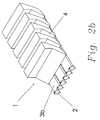
- FIG. 2 bis a prospective view of the system of the present invention with multiple LEDs associated with each light pipe.
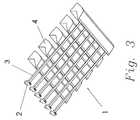
- FIG. 3is an underside prospective view of the system.
- FIG. 4is a side view of the system of the present invention.
- FIG. 5is a detailed broken side view of the system with traces of light rays shown.
- FIG. 5 bis the broken side view with traces of light rays shown with angle A being defined.
- FIG. 6shows the system with a tapered light pipe.
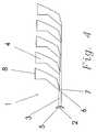
- FIG. 7illustrates the system with a constant thickness light pipe.
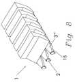
- FIG. 8shows the system with curved directing means to control the light path within the system.
- FIG. 9shows a light pipe system utilizing three dimensional reflectors.
- FIG. 10illustrates a light pipe system utilizing an array of three dimensional reflectors.
- the optical system 1 of the present inventioncomprises a plurality of LEDs 2 situated at a first end 5 of a plurality of light pipes 3 . It should be noted that more than one LED 2 could be associated with each light pipe 3 . It should also be noted that the drawing is not to scale. The LED 2 would be much smaller, or the light pipe 3 could be wider, than depicted in the drawings.
- each LED 2is employed on each light pipe 3 as illustrated in FIG. 2B .
- At least one sensoris positioned so as to monitor the light pipes 3 to determine the actual color or colors being produced by the LEDs 2 .
- Controlling electronicsmonitor the output from the sensors and drive the LEDs 2 to control the color of the output light as desired for the application.
- DMXis one industry standard protocol that can be used to drive the controlling electronics in lighting fixture systems.
- One skilled in the art of LED driver electronicscould devise many different circuits to accomplish the controlling task.
- the preferred embodiment of the optical system 1 illustrated in FIG. 2shows a total of six LEDs 2 generally equally spaced at the first ends 5 of the six light pipes 3 . It should be recognized that the number, size, and spacing of the LEDs 2 and the light pipes 3 would be a function of the particular application of the system.
- the optical system 1further comprises a plurality of reflectors 4 .
- the number of reflectors 4 and the width of the reflectors 4would be much greater than shown in FIG. 2 .
- the preferred embodiment of the optical system 1has a thickness that is much less than the length and width of the system.
- the reflectors 4have been shown with reduced size and number for clarity of illustration.
- the connections of the light pipes 3 to the reflectors 4can best be seen in FIGS. 3 and 4 , an underside perspective and side view respectively, of the optical system 1 .
- Light emitted from the LEDs 2enters the light pipe 3 at the first end 5 of the light pipe 3 .
- the lighttravels down the light pipe 3 via TIR until it enters one of the reflectors 4 .
- Lightmay enter the reflector 4 at either a front edge 6 or a lower edge 7 .
- the path that the light takes from the first end 5 of the light pipe 3 to the reflector 4is shown in greater detail in FIG. 5 .
- Nsis the index of refraction of the medium outside the light pipe.
- the optical system 1is constructed, through materials and geometry selections, so that as large a percentage as is possible of the light emitted from the LEDs 2 TIRs within the light pipe 3 .
- Reflected light ray 11continues to TIR along the light pipe 3 until it encounters either a front edge 6 or a lower edge 7 of one of the reflectors 4 .
- Each reflector 4has preferably the same or greater an index of refraction than the light pipe 3 . If the indexes of the light pipe 3 and the reflector 4 are the same, the reflected light ray 11 continues to travel in the same direction. If the indexes of refraction are slightly different, the reflected light 11 is refracted. If the indexes are much different, and the reflector 4 has a lessor index of refraction, light may again TIR. For most applications, it is undesirable to have any light TIR in the area where the reflector 4 makes contact with the light pipe 3 . Therefore selecting a reflector 4 with an index of refraction greater than that of the light pipe 3 to ensure complete passage of the light is desirable.
- the size and proportions of the front edge 6 and the lower edge 7 of the reflector 4are a function of the desired output for a particular application.
- the ideal relation of these dimensionsis a function of the desired output of the system, the number of reflectors that are attached to the light pipe, the geometry of the reflectors, and the geometry of the light pipe itself.
- One skilled in the artwould be able to select the appropriate dimensions for the reflectors once given the relevant characteristics of the system and the desired output.
- each reflector 4is installed in a notch in the light pipe 3 so that the top of the front edge 6 of the reflector 4 is flush with the upper surface of the light pipe 3 .
- Each successive reflector 4is similarly installed in a notch so that the light pipe 3 is reduced in thickness from the first end 5 to the distal end of the light pipe 3 .
- the reduction in thickness of the light pipe 3chokes down the light ray travel paths to facilitate extraction of the light from the light pipe 3 .
- the rays 11eventually enter one of the reflectors 4 , where the rays 11 are directed from the front and lower edges 6 , 7 to rear surfaces 13 .
- the angle of incidence of the rays 11 with surfaces 13is sufficiently shallow that the resultant reflections are also TIRs. This is desirable, in that TIR reflects a much higher percentage of light than can be obtained with a metallic, or any other type of, reflective coating. Furthermore, utilizing TIR for the output does not require any additional manufacturing steps that would increase the cost of the system.
- the TIR reflected ray 14reflects with generally the same characteristics as the reflective portion of the prior art shown in FIG. 1 . Specifically the magnification does not change significantly as light hits any of the positions along the reflector 4 . In the prior art, due to the disparity of the two light directors, the lens and the reflector, the angle that the light deviates from normal can range from 3.9 to 41 degrees.
- One of the key advantages of the present inventionis that the entire output of the system is from the reflectors 4 . This enables the system to provide extremely accurate control of the output.
- the shape of the reflectors 4is shown as a parabolic. The parabolic shape directs the light in generally a parallel path. Other shapes could be used to create different beam directions and beam widths. The particular application in which the system is to be used determines the specific shape of the reflectors.
- FIG. 6illustrates another method in which the thickness of the light pipe can be reduced.
- FIG. 6shows the light pipe 3 ′ to taper in a gradual manner from the first end 5 .
- the taperis depicted as being linear, but the taper could also be a shallow curved shape.
- the specific shape of the light pipe 3 ′is engineered for the particular application of the system.
- the light pipe of the systemmay have a constant thickness as illustrated in FIG. 7 .
- a light pipe 3 ′′ with constant thicknesscan be ideal when an optical sensor 20 is to be deployed in conjunction with controlling electronics.
- FIG. 8illustrates another modification that can be used to control the direction of travel of light within a light pipe 3 ′′′.
- Light pipe 3 ′′′has a curved or angled first end 15 .
- the reverse taperis shown in the transverse direction, but could also be utilized in the vertical direction, or both transverse and vertical.
- the reverse tapered first end 15directs a greater percentage of the light rays from LED 2 into the light pipe 3 ′′′ in a direction parallel to the longitudinal axis of the light pipe 3 ′′′.
- FIG. 9shows the optical system 1 constructed with 3 D reflectors 4 ′.
- FIG. 10illustrates an array of 3 D reflectors 4 ′ used in the system 1 .
- the 3 D reflectors 4 ′control the output of the system 1 in two dimensions, as opposed to the 2 D reflectors 4 , which control the direction of output light in only one dimension.
Landscapes
- Physics & Mathematics (AREA)
- General Physics & Mathematics (AREA)
- Optics & Photonics (AREA)
- Non-Portable Lighting Devices Or Systems Thereof (AREA)
- Investigating Or Analysing Materials By Optical Means (AREA)
Abstract
Description
A=arcsine(Ns/Nlg)
Where A is the angle (illustrated in
- Nlg is the index of refraction of the light pipe,
Claims (18)
Priority Applications (2)
| Application Number | Priority Date | Filing Date | Title |
|---|---|---|---|
| US12/456,123US8297818B2 (en) | 2009-06-11 | 2009-06-11 | Optical system with reflectors and light pipes |
| PCT/US2010/001661WO2010144137A2 (en) | 2009-06-11 | 2010-06-09 | Optical system with reflectors and light pipes |
Applications Claiming Priority (1)
| Application Number | Priority Date | Filing Date | Title |
|---|---|---|---|
| US12/456,123US8297818B2 (en) | 2009-06-11 | 2009-06-11 | Optical system with reflectors and light pipes |
Publications (2)
| Publication Number | Publication Date |
|---|---|
| US20100220492A1 US20100220492A1 (en) | 2010-09-02 |
| US8297818B2true US8297818B2 (en) | 2012-10-30 |
Family
ID=42666992
Family Applications (1)
| Application Number | Title | Priority Date | Filing Date |
|---|---|---|---|
| US12/456,123Expired - Fee RelatedUS8297818B2 (en) | 2009-06-11 | 2009-06-11 | Optical system with reflectors and light pipes |
Country Status (2)
| Country | Link |
|---|---|
| US (1) | US8297818B2 (en) |
| WO (1) | WO2010144137A2 (en) |
Cited By (22)
| Publication number | Priority date | Publication date | Assignee | Title |
|---|---|---|---|---|
| US20140355302A1 (en)* | 2013-03-15 | 2014-12-04 | Cree, Inc. | Outdoor and/or Enclosed Structure LED Luminaire for General Illumination Applications, Such as Parking Lots and Structures |
| US9291320B2 (en) | 2013-01-30 | 2016-03-22 | Cree, Inc. | Consolidated troffer |
| US9366396B2 (en) | 2013-01-30 | 2016-06-14 | Cree, Inc. | Optical waveguide and lamp including same |
| US9366799B2 (en) | 2013-03-15 | 2016-06-14 | Cree, Inc. | Optical waveguide bodies and luminaires utilizing same |
| US9389367B2 (en) | 2013-01-30 | 2016-07-12 | Cree, Inc. | Optical waveguide and luminaire incorporating same |
| US9411086B2 (en) | 2013-01-30 | 2016-08-09 | Cree, Inc. | Optical waveguide assembly and light engine including same |
| US9442243B2 (en) | 2013-01-30 | 2016-09-13 | Cree, Inc. | Waveguide bodies including redirection features and methods of producing same |
| US9625638B2 (en) | 2013-03-15 | 2017-04-18 | Cree, Inc. | Optical waveguide body |
| US9690029B2 (en) | 2013-01-30 | 2017-06-27 | Cree, Inc. | Optical waveguides and luminaires incorporating same |
| US9798072B2 (en) | 2013-03-15 | 2017-10-24 | Cree, Inc. | Optical element and method of forming an optical element |
| US9869432B2 (en) | 2013-01-30 | 2018-01-16 | Cree, Inc. | Luminaires using waveguide bodies and optical elements |
| US9920901B2 (en) | 2013-03-15 | 2018-03-20 | Cree, Inc. | LED lensing arrangement |
| US10209429B2 (en) | 2013-03-15 | 2019-02-19 | Cree, Inc. | Luminaire with selectable luminous intensity pattern |
| US10234616B2 (en) | 2013-01-30 | 2019-03-19 | Cree, Inc. | Simplified low profile module with light guide for pendant, surface mount, wall mount and stand alone luminaires |
| US10416377B2 (en) | 2016-05-06 | 2019-09-17 | Cree, Inc. | Luminaire with controllable light emission |
| US10436970B2 (en) | 2013-03-15 | 2019-10-08 | Ideal Industries Lighting Llc | Shaped optical waveguide bodies |
| US10502899B2 (en)* | 2013-03-15 | 2019-12-10 | Ideal Industries Lighting Llc | Outdoor and/or enclosed structure LED luminaire |
| US10598851B2 (en) | 2013-08-27 | 2020-03-24 | Nano-Lit Technologies Limited | Light diffuser |
| US10739513B2 (en) | 2018-08-31 | 2020-08-11 | RAB Lighting Inc. | Apparatuses and methods for efficiently directing light toward and away from a mounting surface |
| US10801679B2 (en) | 2018-10-08 | 2020-10-13 | RAB Lighting Inc. | Apparatuses and methods for assembling luminaires |
| US11112083B2 (en) | 2013-03-15 | 2021-09-07 | Ideal Industries Lighting Llc | Optic member for an LED light fixture |
| US11719882B2 (en) | 2016-05-06 | 2023-08-08 | Ideal Industries Lighting Llc | Waveguide-based light sources with dynamic beam shaping |
Families Citing this family (17)
| Publication number | Priority date | Publication date | Assignee | Title |
|---|---|---|---|---|
| US7499206B1 (en)* | 2005-12-09 | 2009-03-03 | Brian Edward Richardson | TIR light valve |
| US8152352B2 (en)* | 2009-01-02 | 2012-04-10 | Rambus International Ltd. | Optic system for light guide with controlled output |
| US8272770B2 (en) | 2009-01-02 | 2012-09-25 | Rambus International Ltd. | TIR switched flat panel display |
| US8152318B2 (en)* | 2009-06-11 | 2012-04-10 | Rambus International Ltd. | Optical system for a light emitting diode with collection, conduction, phosphor directing, and output means |
| US20100315836A1 (en)* | 2009-06-11 | 2010-12-16 | Brian Edward Richardson | Flat panel optical display system with highly controlled output |
| US8297818B2 (en) | 2009-06-11 | 2012-10-30 | Rambus International Ltd. | Optical system with reflectors and light pipes |
| KR20120095437A (en)* | 2009-11-18 | 2012-08-28 | 램버스 인터내셔널 리미티드 | Internal Acquisition Reflective Optics Using Light Emitting Diodes |
| TW201300702A (en) | 2011-05-13 | 2013-01-01 | Rambus Inc | Lighting assembly |
| WO2012169980A1 (en)* | 2011-06-09 | 2012-12-13 | Selimoglu Ozgur | A waveguide for concentrated solar collectors and a solar collector thereof |
| DE202012000567U1 (en)* | 2012-01-20 | 2012-03-01 | Automotive Lighting Reutlingen Gmbh | Lighting device for a motor vehicle |
| AT512544B1 (en)* | 2012-02-16 | 2014-02-15 | Zizala Lichtsysteme Gmbh | METHOD FOR GENERATING A CONTINUOUS EFFECT ON A LIGHTING STRUCTURE AND LIGHTING STRUCTURE |
| CN103292209B (en)* | 2012-03-02 | 2015-06-17 | 赛恩倍吉科技顾问(深圳)有限公司 | Backlight module |
| DE102012209337A1 (en)* | 2012-06-01 | 2013-12-05 | Automotive Lighting Reutlingen Gmbh | Light guide and light guide device |
| US20140233237A1 (en)* | 2013-02-21 | 2014-08-21 | Microsoft Corporation | Light concentrator assembly |
| US9291340B2 (en) | 2013-10-23 | 2016-03-22 | Rambus Delaware Llc | Lighting assembly having n-fold rotational symmetry |
| US20190192879A1 (en)* | 2017-12-22 | 2019-06-27 | Inikoa Medical, Inc. | Disinfecting Methods and Apparatus |
| JP6909393B2 (en)* | 2018-11-09 | 2021-07-28 | 日亜化学工業株式会社 | Optical and lighting equipment |
Citations (97)
| Publication number | Priority date | Publication date | Assignee | Title |
|---|---|---|---|---|
| US223898A (en) | 1879-11-04 | 1880-01-27 | Thomas Alva Edison | Electric lamp |
| GB663840A (en) | 1946-12-18 | 1951-12-27 | Edgar Gretener | A regulable optical illumination system |
| US2673923A (en) | 1947-12-03 | 1954-03-30 | Duro Test Corp | Means for producing colored light beams |
| US2971083A (en) | 1958-11-14 | 1961-02-07 | Gen Electric | Low brightness louver |
| US4172631A (en) | 1975-01-07 | 1979-10-30 | Izon Corporation | Parallel optical fiber and strip illuminating arrays |
| US4392187A (en) | 1981-03-02 | 1983-07-05 | Vari-Lite, Ltd. | Computer controlled lighting system having automatically variable position, color, intensity and beam divergence |
| US4566935A (en) | 1984-07-31 | 1986-01-28 | Texas Instruments Incorporated | Spatial light modulator and method |
| US4596992A (en) | 1984-08-31 | 1986-06-24 | Texas Instruments Incorporated | Linear spatial light modulator and printer |
| US4615595A (en) | 1984-10-10 | 1986-10-07 | Texas Instruments Incorporated | Frame addressed spatial light modulator |
| US4662746A (en) | 1985-10-30 | 1987-05-05 | Texas Instruments Incorporated | Spatial light modulator and method |
| US4710732A (en) | 1984-07-31 | 1987-12-01 | Texas Instruments Incorporated | Spatial light modulator and method |
| US4956619A (en) | 1988-02-19 | 1990-09-11 | Texas Instruments Incorporated | Spatial light modulator |
| US4972306A (en) | 1989-01-23 | 1990-11-20 | Vari-Lite, Inc. | Compact variable diffuser for use in a luminaire |
| US5005108A (en)* | 1989-02-10 | 1991-04-02 | Lumitex, Inc. | Thin panel illuminator |
| US5021928A (en)* | 1982-09-29 | 1991-06-04 | Maurice Daniel | Flat panel illumination system |
| US5028939A (en) | 1988-08-23 | 1991-07-02 | Texas Instruments Incorporated | Spatial light modulator system |
| US5083252A (en) | 1990-04-19 | 1992-01-21 | Tailored Lighting Company, Inc. | Apparatus for producing light distributions |
| US5126886A (en) | 1989-04-10 | 1992-06-30 | Morpheus Lights, Inc. | Scrolling primary color changer |
| US5217285A (en) | 1991-03-15 | 1993-06-08 | The United States Of America As Represented By United States Department Of Energy | Apparatus for synthesis of a solar spectrum |
| US5221987A (en) | 1992-04-10 | 1993-06-22 | Laughlin Richard H | FTIR modulator |
| US5319491A (en) | 1990-08-10 | 1994-06-07 | Continental Typographics, Inc. | Optical display |
| US5396350A (en) | 1993-11-05 | 1995-03-07 | Alliedsignal Inc. | Backlighting apparatus employing an array of microprisms |
| US5467208A (en) | 1992-06-01 | 1995-11-14 | Sharp Kabushiki Kaisha | Liquid crystal display |
| US5631895A (en) | 1994-10-18 | 1997-05-20 | Nec Corporation | Optical information recording medium |
| EP0814300A1 (en) | 1996-06-21 | 1997-12-29 | Casio Computer Company Limited | Surface light source device and liquid crystal display device using the same |
| EP0867747A2 (en) | 1997-03-25 | 1998-09-30 | Sony Corporation | Reflective display device |
| US5825548A (en) | 1997-09-11 | 1998-10-20 | Vari-Lite, Inc. | Cross-fading color filter and system |
| US5936772A (en) | 1997-04-16 | 1999-08-10 | Oympus Optical Co., Ltd. | Light source optical system for endoscopes |
| US5953469A (en) | 1996-10-29 | 1999-09-14 | Xeotron Corporation | Optical device utilizing optical waveguides and mechanical light-switches |
| US5995690A (en)* | 1996-11-21 | 1999-11-30 | Minnesota Mining And Manufacturing Company | Front light extraction film for light guiding systems and method of manufacture |
| EP0969306A1 (en) | 1998-01-20 | 2000-01-05 | Seiko Epson Corporation | Optical switching device and image display device |
| EP0969305A1 (en) | 1998-01-20 | 2000-01-05 | Seiko Epson Corporation | Optical switching device, image display and projection device |
| US6031958A (en)* | 1997-05-21 | 2000-02-29 | Mcgaffigan; Thomas H. | Optical light pipes with laser light appearance |
| US6040937A (en) | 1994-05-05 | 2000-03-21 | Etalon, Inc. | Interferometric modulation |
| US6048081A (en) | 1998-06-15 | 2000-04-11 | Richardson; Brian Edward | Beam divergence and shape controlling module for projected light |
| US6347874B1 (en)* | 2000-02-16 | 2002-02-19 | 3M Innovative Properties Company | Wedge light extractor with risers |
| US6350041B1 (en) | 1999-12-03 | 2002-02-26 | Cree Lighting Company | High output radial dispersing lamp using a solid state light source |
| US6360033B1 (en) | 1999-11-25 | 2002-03-19 | Electronics And Telecommunications Research Institute | Optical switch incorporating therein shallow arch leaf springs |
| US20020044720A1 (en) | 2000-10-17 | 2002-04-18 | Brophy Christopher P. | System for aligning connectors and optical devices |
| EP1215526A1 (en) | 2000-07-11 | 2002-06-19 | Mitsubishi Chemical Corporation | Surface light source device |
| US6421104B1 (en) | 1999-10-22 | 2002-07-16 | Motorola, Inc. | Front illuminator for a liquid crystal display and method of making same |
| US6421103B2 (en) | 1999-12-28 | 2002-07-16 | Fuji Photo Film Co., Ltd. | Liquid-crystal display apparatus including a backlight section using collimating plate |
| US20020105709A1 (en) | 1997-09-04 | 2002-08-08 | Whitehead Lorne A. | Optical switching by controllable frustration of total internal reflection |
| JP2002229017A (en) | 2001-02-07 | 2002-08-14 | Sharp Corp | Display device |
| US6438283B1 (en) | 1999-10-08 | 2002-08-20 | Optical Switch Corporation | Frustrated total internal reflection switch using double pass reflection and method of operation |
| US6502961B1 (en) | 2000-11-20 | 2003-01-07 | Brian Edward Richardson | Conical lens array to control projected light beam color, divergence, and shape |
| EP1291833A2 (en) | 2001-09-06 | 2003-03-12 | Ngk Insulators, Ltd. | Display system with cooling device |
| US6550942B1 (en)* | 1998-04-16 | 2003-04-22 | Alliedsignal Inc. | Linear illumination sources and systems |
| US6565233B1 (en) | 1999-08-17 | 2003-05-20 | Brian Edward Richardson | Color, size and distribution module for projected light |
| US20030147232A1 (en)* | 2002-02-02 | 2003-08-07 | Opti-Flux Technologies | Remote light source general lighting system |
| US6612729B1 (en)* | 2000-03-16 | 2003-09-02 | 3M Innovative Properties Company | Illumination device |
| US6674562B1 (en) | 1994-05-05 | 2004-01-06 | Iridigm Display Corporation | Interferometric modulation of radiation |
| US20040076396A1 (en) | 2001-02-14 | 2004-04-22 | Yoshinori Suga | Light guiding body, light reflective sheet, surface light source device and liquid crystal display device using the light reflective sheet, and method of manufacturing the light reflective sheet |
| US6729734B2 (en) | 2002-04-01 | 2004-05-04 | Hewlett-Packard Development Company, L.P. | System for enhancing the quality of an image |
| US20040109105A1 (en) | 2002-11-29 | 2004-06-10 | Alps Electric Co., Ltd. | Backlight unit and liquid crystal display device |
| US6768572B2 (en) | 1997-10-29 | 2004-07-27 | Teloptics Corporation | Solid state free space switch array on a substrate |
| US6771325B1 (en) | 1999-11-05 | 2004-08-03 | Texas Instruments Incorporated | Color recapture for display systems |
| WO2004068183A2 (en) | 2003-01-27 | 2004-08-12 | 3M Innovative Properties Company | Phosphor based light sources having an polymeric long pass reflector |
| US20040218390A1 (en)* | 2003-01-24 | 2004-11-04 | Digital Optics International Corporation | High-density illumination system |
| US6824270B2 (en) | 2002-08-29 | 2004-11-30 | Samsung Electronics Co., Ltd. | Single-panel color image display apparatus and scrolling method |
| US20050018147A1 (en) | 2003-06-10 | 2005-01-27 | Samsung Electronics Co., Ltd. | Compact LED module and projection display adopting the same |
| US20050057731A1 (en) | 2003-09-17 | 2005-03-17 | Young-Chol Lee | Projection display |
| US6924945B1 (en) | 2003-10-28 | 2005-08-02 | Brian Edward Richardson | Compact light collection system with improved efficiency and reduced size |
| US20050221473A1 (en) | 2004-03-30 | 2005-10-06 | Intel Corporation | Sensor array integrated circuits |
| US20050243570A1 (en) | 2004-04-23 | 2005-11-03 | Chaves Julio C | Optical manifold for light-emitting diodes |
| US20050248827A1 (en) | 2002-03-01 | 2005-11-10 | Starkweather Gary K | Reflective microelectrical mechanical structure (MEMS) optical modulator and optical display system |
| US20050270796A1 (en) | 2004-06-07 | 2005-12-08 | Mitsubishi Denki Kabushiki Kaisha | Planar light source device and display device using the same |
| US6974232B1 (en) | 2003-10-14 | 2005-12-13 | Brian Edward Richardson | Compact lighting system with improved light transmission and color filters |
| US20060070379A1 (en) | 2000-10-31 | 2006-04-06 | Microsoft Corporation | Microelectrical mechanical structure (MEMS) optical modulator and optical display system |
| US7080932B2 (en) | 2004-01-26 | 2006-07-25 | Philips Lumileds Lighting Company, Llc | LED with an optical system to increase luminance by recycling emitted light |
| US7123216B1 (en) | 1994-05-05 | 2006-10-17 | Idc, Llc | Photonic MEMS and structures |
| US7142744B2 (en) | 2001-05-14 | 2006-11-28 | Calient Networks | Wavelength power equalization by attenuation in an optical switch |
| US7144131B2 (en) | 2004-09-29 | 2006-12-05 | Advanced Optical Technologies, Llc | Optical system using LED coupled with phosphor-doped reflective materials |
| US7177498B2 (en) | 2002-03-13 | 2007-02-13 | Altera Corporation | Two-by-two optical routing element using two-position MEMS mirrors |
| US20070133224A1 (en) | 1995-06-27 | 2007-06-14 | Parker Jeffery R | Light emitting panel assemblies |
| US20070176887A1 (en) | 2006-01-31 | 2007-08-02 | Uehara Shin-Ichi | Display device, terminal device, and display panel |
| US20070211487A1 (en) | 2004-09-20 | 2007-09-13 | Koninklijke Philips Electronics, N.V. | Led collimator element with a semiparabolic reflector |
| US7330632B1 (en)* | 2006-08-23 | 2008-02-12 | Energy Focus, Inc. | Fiberoptic luminaire with scattering and specular side-light extractor patterns |
| US7345824B2 (en) | 2002-03-26 | 2008-03-18 | Trivium Technologies, Inc. | Light collimating device |
| WO2008060335A1 (en) | 2006-11-17 | 2008-05-22 | Rensselaer Polytechnic Institute | High-power white leds and manufacturing method thereof |
| US7380962B2 (en) | 2004-04-23 | 2008-06-03 | Light Prescriptions Innovators, Llc | Optical manifold for light-emitting diodes |
| US7400805B2 (en)* | 2003-06-10 | 2008-07-15 | Abu-Ageel Nayef M | Compact light collection system and method |
| US20080247169A1 (en) | 2004-03-16 | 2008-10-09 | Koninklijke Philips Electronics, N.V. | High Brightness Illumination Device With Incoherent Solid State Light Source |
| US7447397B1 (en) | 2004-06-14 | 2008-11-04 | Dynamic Method Enterprises Limited | Optical switch matrix |
| US20080278460A1 (en)* | 2007-05-11 | 2008-11-13 | Rpo Pty Limited | Transmissive Body |
| WO2009024952A2 (en) | 2007-08-23 | 2009-02-26 | Koninklijke Philips Electronics N.V. | Light source including reflective wavelength-converting layer |
| US7499206B1 (en) | 2005-12-09 | 2009-03-03 | Brian Edward Richardson | TIR light valve |
| US20090064993A1 (en) | 2007-09-10 | 2009-03-12 | Banyan Energy, Inc. | Solar energy concentrator |
| EP2045633A1 (en) | 2007-10-04 | 2009-04-08 | Samsung Electronics Co., Ltd. | All-in-one type light guide plate with protrusions of inverted truncated prisms and backlight apparatus employing the same |
| US20090262368A1 (en) | 2008-04-18 | 2009-10-22 | Avago Technologies Ecbu Ip (Singapore) Pte. Ltd. | Light pipe for low profile optical navigation systems |
| US7661862B2 (en)* | 2006-12-07 | 2010-02-16 | Skc Haas Display Films Co., Ltd. | LCD display backlight using elongated illuminators |
| US20100085773A1 (en) | 2009-01-02 | 2010-04-08 | Brian Edward Richardson | Optic system light guide with controlled output |
| US20100172138A1 (en) | 2009-01-02 | 2010-07-08 | Brian Edward Richardson | Tir switched flat panel display |
| US7780330B2 (en)* | 2007-05-16 | 2010-08-24 | Rohm And Haas Electronics Materials Llc | Elongated illuminators configuration for LCD displays |
| US20100220492A1 (en) | 2009-06-11 | 2010-09-02 | Brian Edward Richardson | Optical system with reflectors and light pipes |
| US20100315802A1 (en) | 2009-06-11 | 2010-12-16 | Brian Edward Richardson | Optical system for a Light Emitting Diode with collection, conduction, phosphor directing, and output means |
| US20100315836A1 (en) | 2009-06-11 | 2010-12-16 | Brian Edward Richardson | Flat panel optical display system with highly controlled output |
Family Cites Families (2)
| Publication number | Priority date | Publication date | Assignee | Title |
|---|---|---|---|---|
| DE4224339A1 (en)* | 1992-07-23 | 1994-01-27 | Sel Alcatel Ag | Bus system for a local operations network |
| JPH09261640A (en)* | 1996-03-22 | 1997-10-03 | Oki Electric Ind Co Ltd | Image coder |
- 2009
- 2009-06-11USUS12/456,123patent/US8297818B2/ennot_activeExpired - Fee Related
- 2010
- 2010-06-09WOPCT/US2010/001661patent/WO2010144137A2/enactiveApplication Filing
Patent Citations (104)
| Publication number | Priority date | Publication date | Assignee | Title |
|---|---|---|---|---|
| US223898A (en) | 1879-11-04 | 1880-01-27 | Thomas Alva Edison | Electric lamp |
| GB663840A (en) | 1946-12-18 | 1951-12-27 | Edgar Gretener | A regulable optical illumination system |
| US2673923A (en) | 1947-12-03 | 1954-03-30 | Duro Test Corp | Means for producing colored light beams |
| US2971083A (en) | 1958-11-14 | 1961-02-07 | Gen Electric | Low brightness louver |
| US4172631A (en) | 1975-01-07 | 1979-10-30 | Izon Corporation | Parallel optical fiber and strip illuminating arrays |
| US4392187A (en) | 1981-03-02 | 1983-07-05 | Vari-Lite, Ltd. | Computer controlled lighting system having automatically variable position, color, intensity and beam divergence |
| US5021928A (en)* | 1982-09-29 | 1991-06-04 | Maurice Daniel | Flat panel illumination system |
| US4710732A (en) | 1984-07-31 | 1987-12-01 | Texas Instruments Incorporated | Spatial light modulator and method |
| US4566935A (en) | 1984-07-31 | 1986-01-28 | Texas Instruments Incorporated | Spatial light modulator and method |
| US4596992A (en) | 1984-08-31 | 1986-06-24 | Texas Instruments Incorporated | Linear spatial light modulator and printer |
| US4615595A (en) | 1984-10-10 | 1986-10-07 | Texas Instruments Incorporated | Frame addressed spatial light modulator |
| US4662746A (en) | 1985-10-30 | 1987-05-05 | Texas Instruments Incorporated | Spatial light modulator and method |
| US4956619A (en) | 1988-02-19 | 1990-09-11 | Texas Instruments Incorporated | Spatial light modulator |
| US5028939A (en) | 1988-08-23 | 1991-07-02 | Texas Instruments Incorporated | Spatial light modulator system |
| US4972306A (en) | 1989-01-23 | 1990-11-20 | Vari-Lite, Inc. | Compact variable diffuser for use in a luminaire |
| US5005108A (en)* | 1989-02-10 | 1991-04-02 | Lumitex, Inc. | Thin panel illuminator |
| US5126886A (en) | 1989-04-10 | 1992-06-30 | Morpheus Lights, Inc. | Scrolling primary color changer |
| US5083252A (en) | 1990-04-19 | 1992-01-21 | Tailored Lighting Company, Inc. | Apparatus for producing light distributions |
| US5319491A (en) | 1990-08-10 | 1994-06-07 | Continental Typographics, Inc. | Optical display |
| US5217285A (en) | 1991-03-15 | 1993-06-08 | The United States Of America As Represented By United States Department Of Energy | Apparatus for synthesis of a solar spectrum |
| US5221987A (en) | 1992-04-10 | 1993-06-22 | Laughlin Richard H | FTIR modulator |
| US5467208A (en) | 1992-06-01 | 1995-11-14 | Sharp Kabushiki Kaisha | Liquid crystal display |
| US5396350A (en) | 1993-11-05 | 1995-03-07 | Alliedsignal Inc. | Backlighting apparatus employing an array of microprisms |
| US6040937A (en) | 1994-05-05 | 2000-03-21 | Etalon, Inc. | Interferometric modulation |
| US6674562B1 (en) | 1994-05-05 | 2004-01-06 | Iridigm Display Corporation | Interferometric modulation of radiation |
| US6867896B2 (en) | 1994-05-05 | 2005-03-15 | Idc, Llc | Interferometric modulation of radiation |
| US7123216B1 (en) | 1994-05-05 | 2006-10-17 | Idc, Llc | Photonic MEMS and structures |
| US5631895A (en) | 1994-10-18 | 1997-05-20 | Nec Corporation | Optical information recording medium |
| US20070133224A1 (en) | 1995-06-27 | 2007-06-14 | Parker Jeffery R | Light emitting panel assemblies |
| EP0814300A1 (en) | 1996-06-21 | 1997-12-29 | Casio Computer Company Limited | Surface light source device and liquid crystal display device using the same |
| US5953469A (en) | 1996-10-29 | 1999-09-14 | Xeotron Corporation | Optical device utilizing optical waveguides and mechanical light-switches |
| US5995690A (en)* | 1996-11-21 | 1999-11-30 | Minnesota Mining And Manufacturing Company | Front light extraction film for light guiding systems and method of manufacture |
| EP0867747A2 (en) | 1997-03-25 | 1998-09-30 | Sony Corporation | Reflective display device |
| US5936772A (en) | 1997-04-16 | 1999-08-10 | Oympus Optical Co., Ltd. | Light source optical system for endoscopes |
| US6031958A (en)* | 1997-05-21 | 2000-02-29 | Mcgaffigan; Thomas H. | Optical light pipes with laser light appearance |
| US20020105709A1 (en) | 1997-09-04 | 2002-08-08 | Whitehead Lorne A. | Optical switching by controllable frustration of total internal reflection |
| US5825548A (en) | 1997-09-11 | 1998-10-20 | Vari-Lite, Inc. | Cross-fading color filter and system |
| US6768572B2 (en) | 1997-10-29 | 2004-07-27 | Teloptics Corporation | Solid state free space switch array on a substrate |
| EP0969306A1 (en) | 1998-01-20 | 2000-01-05 | Seiko Epson Corporation | Optical switching device and image display device |
| US20020031294A1 (en) | 1998-01-20 | 2002-03-14 | Takashi Takeda | Optical switching device and image display device |
| EP0969305A1 (en) | 1998-01-20 | 2000-01-05 | Seiko Epson Corporation | Optical switching device, image display and projection device |
| US6550942B1 (en)* | 1998-04-16 | 2003-04-22 | Alliedsignal Inc. | Linear illumination sources and systems |
| US6048081A (en) | 1998-06-15 | 2000-04-11 | Richardson; Brian Edward | Beam divergence and shape controlling module for projected light |
| US6565233B1 (en) | 1999-08-17 | 2003-05-20 | Brian Edward Richardson | Color, size and distribution module for projected light |
| US6438283B1 (en) | 1999-10-08 | 2002-08-20 | Optical Switch Corporation | Frustrated total internal reflection switch using double pass reflection and method of operation |
| US6421104B1 (en) | 1999-10-22 | 2002-07-16 | Motorola, Inc. | Front illuminator for a liquid crystal display and method of making same |
| US6771325B1 (en) | 1999-11-05 | 2004-08-03 | Texas Instruments Incorporated | Color recapture for display systems |
| US6360033B1 (en) | 1999-11-25 | 2002-03-19 | Electronics And Telecommunications Research Institute | Optical switch incorporating therein shallow arch leaf springs |
| US6350041B1 (en) | 1999-12-03 | 2002-02-26 | Cree Lighting Company | High output radial dispersing lamp using a solid state light source |
| US6421103B2 (en) | 1999-12-28 | 2002-07-16 | Fuji Photo Film Co., Ltd. | Liquid-crystal display apparatus including a backlight section using collimating plate |
| US6379016B1 (en)* | 2000-02-16 | 2002-04-30 | 3M Innovative Properties Company | Light guide with extraction structures |
| US6347874B1 (en)* | 2000-02-16 | 2002-02-19 | 3M Innovative Properties Company | Wedge light extractor with risers |
| US6612729B1 (en)* | 2000-03-16 | 2003-09-02 | 3M Innovative Properties Company | Illumination device |
| EP1215526A1 (en) | 2000-07-11 | 2002-06-19 | Mitsubishi Chemical Corporation | Surface light source device |
| US20020044720A1 (en) | 2000-10-17 | 2002-04-18 | Brophy Christopher P. | System for aligning connectors and optical devices |
| US20060070379A1 (en) | 2000-10-31 | 2006-04-06 | Microsoft Corporation | Microelectrical mechanical structure (MEMS) optical modulator and optical display system |
| US6502961B1 (en) | 2000-11-20 | 2003-01-07 | Brian Edward Richardson | Conical lens array to control projected light beam color, divergence, and shape |
| JP2002229017A (en) | 2001-02-07 | 2002-08-14 | Sharp Corp | Display device |
| US20040076396A1 (en) | 2001-02-14 | 2004-04-22 | Yoshinori Suga | Light guiding body, light reflective sheet, surface light source device and liquid crystal display device using the light reflective sheet, and method of manufacturing the light reflective sheet |
| US7142744B2 (en) | 2001-05-14 | 2006-11-28 | Calient Networks | Wavelength power equalization by attenuation in an optical switch |
| EP1291833A2 (en) | 2001-09-06 | 2003-03-12 | Ngk Insulators, Ltd. | Display system with cooling device |
| US20030147232A1 (en)* | 2002-02-02 | 2003-08-07 | Opti-Flux Technologies | Remote light source general lighting system |
| US20050248827A1 (en) | 2002-03-01 | 2005-11-10 | Starkweather Gary K | Reflective microelectrical mechanical structure (MEMS) optical modulator and optical display system |
| US7177498B2 (en) | 2002-03-13 | 2007-02-13 | Altera Corporation | Two-by-two optical routing element using two-position MEMS mirrors |
| US7345824B2 (en) | 2002-03-26 | 2008-03-18 | Trivium Technologies, Inc. | Light collimating device |
| US6729734B2 (en) | 2002-04-01 | 2004-05-04 | Hewlett-Packard Development Company, L.P. | System for enhancing the quality of an image |
| US6824270B2 (en) | 2002-08-29 | 2004-11-30 | Samsung Electronics Co., Ltd. | Single-panel color image display apparatus and scrolling method |
| US20040109105A1 (en) | 2002-11-29 | 2004-06-10 | Alps Electric Co., Ltd. | Backlight unit and liquid crystal display device |
| US20040218390A1 (en)* | 2003-01-24 | 2004-11-04 | Digital Optics International Corporation | High-density illumination system |
| WO2004068183A2 (en) | 2003-01-27 | 2004-08-12 | 3M Innovative Properties Company | Phosphor based light sources having an polymeric long pass reflector |
| US7400805B2 (en)* | 2003-06-10 | 2008-07-15 | Abu-Ageel Nayef M | Compact light collection system and method |
| US20050018147A1 (en) | 2003-06-10 | 2005-01-27 | Samsung Electronics Co., Ltd. | Compact LED module and projection display adopting the same |
| US20050057731A1 (en) | 2003-09-17 | 2005-03-17 | Young-Chol Lee | Projection display |
| US6974232B1 (en) | 2003-10-14 | 2005-12-13 | Brian Edward Richardson | Compact lighting system with improved light transmission and color filters |
| US6924945B1 (en) | 2003-10-28 | 2005-08-02 | Brian Edward Richardson | Compact light collection system with improved efficiency and reduced size |
| US7080932B2 (en) | 2004-01-26 | 2006-07-25 | Philips Lumileds Lighting Company, Llc | LED with an optical system to increase luminance by recycling emitted light |
| US20080247169A1 (en) | 2004-03-16 | 2008-10-09 | Koninklijke Philips Electronics, N.V. | High Brightness Illumination Device With Incoherent Solid State Light Source |
| US20050221473A1 (en) | 2004-03-30 | 2005-10-06 | Intel Corporation | Sensor array integrated circuits |
| US7380962B2 (en) | 2004-04-23 | 2008-06-03 | Light Prescriptions Innovators, Llc | Optical manifold for light-emitting diodes |
| US7286296B2 (en) | 2004-04-23 | 2007-10-23 | Light Prescriptions Innovators, Llc | Optical manifold for light-emitting diodes |
| US20080170296A1 (en) | 2004-04-23 | 2008-07-17 | Light Prescriptions Innovators, Llc | Optical devices |
| US20050243570A1 (en) | 2004-04-23 | 2005-11-03 | Chaves Julio C | Optical manifold for light-emitting diodes |
| US20050270796A1 (en) | 2004-06-07 | 2005-12-08 | Mitsubishi Denki Kabushiki Kaisha | Planar light source device and display device using the same |
| US7447397B1 (en) | 2004-06-14 | 2008-11-04 | Dynamic Method Enterprises Limited | Optical switch matrix |
| US20070211487A1 (en) | 2004-09-20 | 2007-09-13 | Koninklijke Philips Electronics, N.V. | Led collimator element with a semiparabolic reflector |
| US7144131B2 (en) | 2004-09-29 | 2006-12-05 | Advanced Optical Technologies, Llc | Optical system using LED coupled with phosphor-doped reflective materials |
| US20090116099A1 (en) | 2005-12-09 | 2009-05-07 | Brian Edward Richardson | Tir light valve |
| US20100328748A1 (en) | 2005-12-09 | 2010-12-30 | Brian Edward Richardson | TIR Light Valve |
| US7499206B1 (en) | 2005-12-09 | 2009-03-03 | Brian Edward Richardson | TIR light valve |
| US20070176887A1 (en) | 2006-01-31 | 2007-08-02 | Uehara Shin-Ichi | Display device, terminal device, and display panel |
| US7330632B1 (en)* | 2006-08-23 | 2008-02-12 | Energy Focus, Inc. | Fiberoptic luminaire with scattering and specular side-light extractor patterns |
| WO2008060335A1 (en) | 2006-11-17 | 2008-05-22 | Rensselaer Polytechnic Institute | High-power white leds and manufacturing method thereof |
| US7661862B2 (en)* | 2006-12-07 | 2010-02-16 | Skc Haas Display Films Co., Ltd. | LCD display backlight using elongated illuminators |
| US20080278460A1 (en)* | 2007-05-11 | 2008-11-13 | Rpo Pty Limited | Transmissive Body |
| US7780330B2 (en)* | 2007-05-16 | 2010-08-24 | Rohm And Haas Electronics Materials Llc | Elongated illuminators configuration for LCD displays |
| WO2009024952A2 (en) | 2007-08-23 | 2009-02-26 | Koninklijke Philips Electronics N.V. | Light source including reflective wavelength-converting layer |
| US20090064993A1 (en) | 2007-09-10 | 2009-03-12 | Banyan Energy, Inc. | Solar energy concentrator |
| EP2045633A1 (en) | 2007-10-04 | 2009-04-08 | Samsung Electronics Co., Ltd. | All-in-one type light guide plate with protrusions of inverted truncated prisms and backlight apparatus employing the same |
| US20090262368A1 (en) | 2008-04-18 | 2009-10-22 | Avago Technologies Ecbu Ip (Singapore) Pte. Ltd. | Light pipe for low profile optical navigation systems |
| US20100085773A1 (en) | 2009-01-02 | 2010-04-08 | Brian Edward Richardson | Optic system light guide with controlled output |
| US20100172138A1 (en) | 2009-01-02 | 2010-07-08 | Brian Edward Richardson | Tir switched flat panel display |
| US20100220492A1 (en) | 2009-06-11 | 2010-09-02 | Brian Edward Richardson | Optical system with reflectors and light pipes |
| US20100315802A1 (en) | 2009-06-11 | 2010-12-16 | Brian Edward Richardson | Optical system for a Light Emitting Diode with collection, conduction, phosphor directing, and output means |
| US20100315836A1 (en) | 2009-06-11 | 2010-12-16 | Brian Edward Richardson | Flat panel optical display system with highly controlled output |
Non-Patent Citations (22)
| Title |
|---|
| Decision of Petition to Make Special under the Green Technology Pilot Program (Dismissed) with mail date of Feb. 22, 2010, re U.S. Appl. No. 12/319,172. |
| Decision of Petition to Make Special under the Green Technology Pilot Program (Dismissed) with mail date of Jul. 13, 2010, re U.S. Appl. No. 12/319,172. |
| Decision on Petition to Make Special under the Green Technology Program (Denied) with mail date of Aug. 27, 2010, re U.S. Appl. No. 12/319,172. |
| Decision on Petition to Make Special under the Green Technology Program (Denied) with mail date of Oct. 14, 2010, re U.S. Appl. No. 12/319,172. |
| Information Disclosure Statement with a mail date of Sep. 8, 2010, re U.S. Appl. No. 12/319,172. |
| Information Disclosure Statement with mail date of Mar. 24, 2010, re U.S. Appl. No. 12/319,172. |
| Information Disclosure Statement with mail date of Mar. 25, 2010, re U.S. Appl. No. 12/319,171. |
| Information Disclosure Statement with mail date of Sep. 8, 2010, re U.S. Appl. No. 12/319,171. |
| International Search Report and the Written Opinion with mail date of Feb. 18, 2011, re Int'l Application No. PCT/US2010/001673. |
| International Search Report and the Written Opinion with mail date of Feb. 7, 2011, re Int'l Application No. PCT/US2010/001661. |
| International Search Report and the Written Opinion with mail date of Mar. 4, 2011, re Int'l Application No. PCT/US2010/001674. |
| International Search Report and the Written Opinion with mail date of Sep. 13, 2010, re Int'l. Application No. PCT/US2009/006763. |
| Non-Final Office Action with mail date of Oct. 21, 2010, re U.S. Appl. No. 12/319,172. |
| Preliminary Amendment with mail date of Apr. 12, 2010, re U.S. Appl. No. 12/319,172. |
| Preliminary Amendment with mail date of Aug. 13, 2010, re U.S. Appl. No. 12/319,172. |
| Preliminary Amendment with mail date of Sep. 7, 2010, re U.S. Appl. No. 12/319,172. |
| Renewed Petition for Green Tech Pilot Program with mail date of Aug. 13, 2010, re U.S. Appl. No. 12/319,172. |
| Renewed Petition for Green Tech Pilot Program with mail date of Jun. 10, 2010, re U.S. Appl. No. 12/319,172. |
| Renewed Petition for Green Technology Pilot Program with mail date of Sep. 7, 2010, re U.S. Appl. No. 12/319,172. |
| Response to Office Action of Oct. 21, 2010 with mail date of Mar. 21, 2011, re U.S. Appl. No. 12/319,172. |
| Statement of Special Status in Support of Petition to Make Special under the Green Technology Pilot Program with mail date of Dec. 22, 2009, re U.S. Appl. No. 12/319,172. |
| Statement of Special Status in Support of Petition to Make Special under the Green Technology Pilot Program with mail date of Oct. 22, 2010, re U.S. Appl. No. 12/319,172. |
Cited By (33)
| Publication number | Priority date | Publication date | Assignee | Title |
|---|---|---|---|---|
| US10234616B2 (en) | 2013-01-30 | 2019-03-19 | Cree, Inc. | Simplified low profile module with light guide for pendant, surface mount, wall mount and stand alone luminaires |
| US9291320B2 (en) | 2013-01-30 | 2016-03-22 | Cree, Inc. | Consolidated troffer |
| US9366396B2 (en) | 2013-01-30 | 2016-06-14 | Cree, Inc. | Optical waveguide and lamp including same |
| US11644157B2 (en) | 2013-01-30 | 2023-05-09 | Ideal Industries Lighting Llc | Luminaires using waveguide bodies and optical elements |
| US9389367B2 (en) | 2013-01-30 | 2016-07-12 | Cree, Inc. | Optical waveguide and luminaire incorporating same |
| US9411086B2 (en) | 2013-01-30 | 2016-08-09 | Cree, Inc. | Optical waveguide assembly and light engine including same |
| US9442243B2 (en) | 2013-01-30 | 2016-09-13 | Cree, Inc. | Waveguide bodies including redirection features and methods of producing same |
| US9519095B2 (en) | 2013-01-30 | 2016-12-13 | Cree, Inc. | Optical waveguides |
| US9581751B2 (en) | 2013-01-30 | 2017-02-28 | Cree, Inc. | Optical waveguide and lamp including same |
| US11070493B2 (en) | 2013-01-30 | 2021-07-20 | Ideal Industries Lighting Llc | Simplified low profile module with light guide for pendant, surface mount, wall mount and stand alone luminaires |
| US9690029B2 (en) | 2013-01-30 | 2017-06-27 | Cree, Inc. | Optical waveguides and luminaires incorporating same |
| US10436969B2 (en) | 2013-01-30 | 2019-10-08 | Ideal Industries Lighting Llc | Optical waveguide and luminaire incorporating same |
| US9823408B2 (en) | 2013-01-30 | 2017-11-21 | Cree, Inc. | Optical waveguide and luminaire incorporating same |
| US9869432B2 (en) | 2013-01-30 | 2018-01-16 | Cree, Inc. | Luminaires using waveguide bodies and optical elements |
| US10379278B2 (en)* | 2013-03-15 | 2019-08-13 | Ideal Industries Lighting Llc | Outdoor and/or enclosed structure LED luminaire outdoor and/or enclosed structure LED luminaire having outward illumination |
| US9625638B2 (en) | 2013-03-15 | 2017-04-18 | Cree, Inc. | Optical waveguide body |
| US9920901B2 (en) | 2013-03-15 | 2018-03-20 | Cree, Inc. | LED lensing arrangement |
| US9366799B2 (en) | 2013-03-15 | 2016-06-14 | Cree, Inc. | Optical waveguide bodies and luminaires utilizing same |
| US20140355302A1 (en)* | 2013-03-15 | 2014-12-04 | Cree, Inc. | Outdoor and/or Enclosed Structure LED Luminaire for General Illumination Applications, Such as Parking Lots and Structures |
| US10436970B2 (en) | 2013-03-15 | 2019-10-08 | Ideal Industries Lighting Llc | Shaped optical waveguide bodies |
| US9798072B2 (en) | 2013-03-15 | 2017-10-24 | Cree, Inc. | Optical element and method of forming an optical element |
| US10502899B2 (en)* | 2013-03-15 | 2019-12-10 | Ideal Industries Lighting Llc | Outdoor and/or enclosed structure LED luminaire |
| US11112083B2 (en) | 2013-03-15 | 2021-09-07 | Ideal Industries Lighting Llc | Optic member for an LED light fixture |
| US10209429B2 (en) | 2013-03-15 | 2019-02-19 | Cree, Inc. | Luminaire with selectable luminous intensity pattern |
| US10598851B2 (en) | 2013-08-27 | 2020-03-24 | Nano-Lit Technologies Limited | Light diffuser |
| US10890714B2 (en) | 2016-05-06 | 2021-01-12 | Ideal Industries Lighting Llc | Waveguide-based light sources with dynamic beam shaping |
| US10527785B2 (en) | 2016-05-06 | 2020-01-07 | Ideal Industries Lighting Llc | Waveguide-based light sources with dynamic beam shaping |
| US11372156B2 (en) | 2016-05-06 | 2022-06-28 | Ideal Industries Lighting Llc | Waveguide-based light sources with dynamic beam shaping |
| US10416377B2 (en) | 2016-05-06 | 2019-09-17 | Cree, Inc. | Luminaire with controllable light emission |
| US11719882B2 (en) | 2016-05-06 | 2023-08-08 | Ideal Industries Lighting Llc | Waveguide-based light sources with dynamic beam shaping |
| US12353005B2 (en) | 2016-05-06 | 2025-07-08 | Cree Lighting Usa Llc | Waveguide-based light sources with dynamic beam shaping |
| US10739513B2 (en) | 2018-08-31 | 2020-08-11 | RAB Lighting Inc. | Apparatuses and methods for efficiently directing light toward and away from a mounting surface |
| US10801679B2 (en) | 2018-10-08 | 2020-10-13 | RAB Lighting Inc. | Apparatuses and methods for assembling luminaires |
Also Published As
| Publication number | Publication date |
|---|---|
| WO2010144137A3 (en) | 2011-03-24 |
| WO2010144137A2 (en) | 2010-12-16 |
| US20100220492A1 (en) | 2010-09-02 |
Similar Documents
| Publication | Publication Date | Title |
|---|---|---|
| US8297818B2 (en) | Optical system with reflectors and light pipes | |
| US11822113B2 (en) | Daylight responsive LED illumination panel with color temperature control | |
| US8152352B2 (en) | Optic system for light guide with controlled output | |
| US8641257B2 (en) | Optic system for light guide with controlled output | |
| JP6688744B2 (en) | Optical system with variable viewing angle | |
| CA2343281C (en) | Illumination system using edge-illuminated hollow waveguide and lenticular optical structures | |
| JP3488467B2 (en) | Illumination system using an array of microprisms | |
| US20060250707A1 (en) | Optical film having a surface with rounded pyramidal structures | |
| US20060103777A1 (en) | Optical film having a structured surface with rectangular based prisms | |
| US20100265720A1 (en) | Reflector and system | |
| US8287172B2 (en) | Planar illumination device | |
| CN101095077A (en) | Optical film having a structured surface with concave pyramid-shaped structures | |
| KR20070003873A (en) | Brightness improving film, lighting device, display device, light guide plate and method of improving light emission | |
| US20100315836A1 (en) | Flat panel optical display system with highly controlled output | |
| US20070064440A1 (en) | Light guide device and backlight module using the same | |
| EP2384455A2 (en) | Light guide system for extracting light with controlled output | |
| US20210088711A1 (en) | Wedge lightguide | |
| US20130100657A1 (en) | Planar illuminating device | |
| CN102027397A (en) | A directional light source using refractive and reflective optics | |
| US20070153546A1 (en) | Light-emitting Device and Back Light Unit with Light Emitting Diodes | |
| US20150205031A1 (en) | Illumination device based on light guide with light scattering particles and light angle selection module | |
| CN100395610C (en) | light guide plate | |
| CN108873143B (en) | Backlight module and light source adjusting device thereof | |
| JP5614634B2 (en) | Surface light source device, liquid crystal display device, and optical member | |
| US20090147539A1 (en) | Optical assembly |
Legal Events
| Date | Code | Title | Description |
|---|---|---|---|
| AS | Assignment | Owner name:IMAGINE ILLUMINATION, LLC, CALIFORNIA Free format text:ASSIGNMENT OF ASSIGNORS INTEREST;ASSIGNORS:RICHARDSON, BRIAN E.;RICHARDSON, EILEEN H.;IMAGINE DESIGNS, INC.;REEL/FRAME:026137/0717 Effective date:20101223 Owner name:RAMBUS INTERNATIONAL LTD., CAYMAN ISLANDS Free format text:ASSIGNMENT OF ASSIGNORS INTEREST;ASSIGNOR:IMAGINE ILLUMINATION, LLC;REEL/FRAME:026137/0778 Effective date:20101223 | |
| STCF | Information on status: patent grant | Free format text:PATENTED CASE | |
| AS | Assignment | Owner name:RAMBUS DELAWARE, OHIO Free format text:ASSIGNMENT OF ASSIGNORS INTEREST;ASSIGNOR:RAMBUS INC.;REEL/FRAME:029967/0165 Effective date:20121001 Owner name:RAMBUS INC., CALIFORNIA Free format text:ASSIGNMENT OF ASSIGNORS INTEREST;ASSIGNOR:RAMBUS INTERNATIONAL LTD.;REEL/FRAME:029960/0421 Effective date:20101001 | |
| AS | Assignment | Owner name:RAMBUS DELAWARE LLC, OHIO Free format text:ASSIGNMENT OF ASSIGNORS INTEREST;ASSIGNOR:RAMBUS INTERNATIONAL LTD.;REEL/FRAME:033881/0001 Effective date:20121001 | |
| FPAY | Fee payment | Year of fee payment:4 | |
| FEPP | Fee payment procedure | Free format text:MAINTENANCE FEE REMINDER MAILED (ORIGINAL EVENT CODE: REM.); ENTITY STATUS OF PATENT OWNER: LARGE ENTITY | |
| LAPS | Lapse for failure to pay maintenance fees | Free format text:PATENT EXPIRED FOR FAILURE TO PAY MAINTENANCE FEES (ORIGINAL EVENT CODE: EXP.); ENTITY STATUS OF PATENT OWNER: LARGE ENTITY | |
| STCH | Information on status: patent discontinuation | Free format text:PATENT EXPIRED DUE TO NONPAYMENT OF MAINTENANCE FEES UNDER 37 CFR 1.362 | |
| FP | Lapsed due to failure to pay maintenance fee | Effective date:20201030 |