US8297659B2 - Quick connector assembly - Google Patents
Quick connector assemblyDownload PDFInfo
- Publication number
- US8297659B2 US8297659B2US13/031,846US201113031846AUS8297659B2US 8297659 B2US8297659 B2US 8297659B2US 201113031846 AUS201113031846 AUS 201113031846AUS 8297659 B2US8297659 B2US 8297659B2
- Authority
- US
- United States
- Prior art keywords
- retaining
- receiving member
- connector assembly
- quick connector
- set forth
- Prior art date
- Legal status (The legal status is an assumption and is not a legal conclusion. Google has not performed a legal analysis and makes no representation as to the accuracy of the status listed.)
- Active, expires
Links
- 238000003780insertionMethods0.000claimsabstractdescription115
- 230000037431insertionEffects0.000claimsabstractdescription115
- 230000000903blocking effectEffects0.000claimsabstractdescription30
- 239000012530fluidSubstances0.000claimsdescription6
- 210000002445nippleAnatomy0.000description5
- 230000000712assemblyEffects0.000description4
- 238000000429assemblyMethods0.000description4
- 239000000446fuelSubstances0.000description3
- 239000000463materialSubstances0.000description2
- 239000011347resinSubstances0.000description2
- 229920005989resinPolymers0.000description2
- 239000007788liquidSubstances0.000description1
- 238000012986modificationMethods0.000description1
- 230000004048modificationEffects0.000description1
- 238000009423ventilationMethods0.000description1
Images


Classifications
- F—MECHANICAL ENGINEERING; LIGHTING; HEATING; WEAPONS; BLASTING
- F16—ENGINEERING ELEMENTS AND UNITS; GENERAL MEASURES FOR PRODUCING AND MAINTAINING EFFECTIVE FUNCTIONING OF MACHINES OR INSTALLATIONS; THERMAL INSULATION IN GENERAL
- F16L—PIPES; JOINTS OR FITTINGS FOR PIPES; SUPPORTS FOR PIPES, CABLES OR PROTECTIVE TUBING; MEANS FOR THERMAL INSULATION IN GENERAL
- F16L37/00—Couplings of the quick-acting type
- F16L37/08—Couplings of the quick-acting type in which the connection between abutting or axially overlapping ends is maintained by locking members
- F16L37/12—Couplings of the quick-acting type in which the connection between abutting or axially overlapping ends is maintained by locking members using hooks, pawls, or other movable or insertable locking members
- F16L37/14—Joints secured by inserting between mating surfaces an element, e.g. a piece of wire, a pin, a chain
- F16L37/142—Joints secured by inserting between mating surfaces an element, e.g. a piece of wire, a pin, a chain where the securing element is inserted tangentially
- F16L37/144—Joints secured by inserting between mating surfaces an element, e.g. a piece of wire, a pin, a chain where the securing element is inserted tangentially the securing element being U-shaped
- F—MECHANICAL ENGINEERING; LIGHTING; HEATING; WEAPONS; BLASTING
- F16—ENGINEERING ELEMENTS AND UNITS; GENERAL MEASURES FOR PRODUCING AND MAINTAINING EFFECTIVE FUNCTIONING OF MACHINES OR INSTALLATIONS; THERMAL INSULATION IN GENERAL
- F16L—PIPES; JOINTS OR FITTINGS FOR PIPES; SUPPORTS FOR PIPES, CABLES OR PROTECTIVE TUBING; MEANS FOR THERMAL INSULATION IN GENERAL
- F16L2201/00—Special arrangements for pipe couplings
- F16L2201/10—Indicators for correct coupling
Definitions
- a quick connector assemblyfor securing an insertion member within a receiving member to convey fluids between the insertion member and the receiving member.
- Quick connector assembliesare used prevalently for connecting fuel tubes of automotive fuel systems to establish a continuous flow path therebetween.
- quick connectorsare used in various air/vapor management systems such as evaporative emissions systems, crankcase ventilation systems, and brake boost and engine vacuum systems.
- quick connectorscan also be used in fluid delivery systems such as, for example, liquid fuel and windshield washer applications.
- Quick connector assembliesare capable of quickly and simply connecting tubes or conduits to one another.
- Quick connector assembliessecure an insertion member within a receiving member to convey fluids through the insertion and receiving members.
- Various quick connector assembliesare well known.
- One known quick connector assemblyincludes a retaining member for holding an insertion member in a receiving member.
- the retaining memberis inserted perpendicular to a longitudinal axis to secure the insertion member relative to the receiving member.
- the receiving memberincludes a blocking part that is unitary with the receiving member and includes a pair of blocking edges that extend to the axial bore defined in the receiving member to block the movement of the retaining member.
- the retaining memberincludes a pair of unitary verifying legs that are orientated in the direction of insertion and engage the blocking edges to block the movement of the retaining member. The verifying legs are moved outwardly away from each other by the annular collar of the insertion member, when the insertion member is pressed a sufficient distance into the receiving member. As a result of this outward movement, the verifying legs are no longer blocked by the blocking member, and the retaining member may be inserted to engage the insertion member and secure the insertion member relative to the receiving member.
- Another such quick connector assemblyincludes a retaining member for keeping an insertion member in a receiving member.
- the retaining memberis inserted perpendicular to a longitudinal axis to secure the insertion member relative to the receiving member.
- the receiving memberincludes a latching projection that is unitary with the receiving member to block the movement of the retaining member.
- the retaining memberincludes a pair of unitary latching arms that are orientated perpendicular to the direction of insertion and biased upwardly to engage the latching projection and block the movement of the retaining member.
- the latching armsare moved downwardly by the annular collar of the insertion member, when the insertion member is pressed a sufficient distance into the receiving member. As a result of this downward movement, the latching arms are no longer blocked by the latching projection, and the retaining member may be inserted to engage the insertion member and secure the insertion member relative to the receiving member.
- the present inventionrelates to a quick connector assembly that secures an insertion member within a receiving member to convey fluids between the insertion member and the receiving member.
- the receiving memberincludes an axial bore that extends along a longitudinal axis between a receiving member top and a receiving member bottom.
- a retaining slotis defined by the receiving member and extends perpendicularly to the longitudinal axis and through the receiving member.
- the insertion memberincludes an annular collar that extends outwardly from a shaft portion.
- the insertion memberis axially inserted within the axial bore of the receiving member.
- a retaining memberis disposed in the receiving member for movement in the retaining slot.
- the retaining memberis moveable to a fully inserted position in a direction of insertion.
- the retaining memberengages the insertion member when the insertion member is in the fully inserted position and secures the insertion member relative to receiving member.
- a positioning memberis disposed in the axial bore and includes a base portion and a biasing portion biased towards the receiving member top.
- the positioning memberis a separate and distinct structure from both the receiving member and retaining member.
- the biasing portionextends angularly from the base portion to a pair of blocking portions.
- the blocking portionsare movable between an extended position and a retracted position.
- the blocking portionsare oriented opposite the direction of insertion of the retaining member to block the retaining member from moving into the fully inserted position when the biasing portion is in the extended position.
- the annular collar of the insertion memberengages the blocking portions of the positioning member when the insertion member is axially inserted in the axial bore in a direction opposite the bias of the biasing portion.
- the annular collarmoves the blocking portions away from the retaining slot and into the retracted position.
- FIG. 1is an exploded perspective view of a quick connector assembly according to the subject invention
- FIG. 2is an exploded side view of the quick connector assembly according to the subject invention
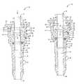
- FIG. 3is a partially exploded, cross-sectional view of the quick connector assembly showing an insertion member prior to insertion into a receiving member according to the subject invention
- FIG. 4is a cross-sectional view of the quick connector assembly showing the insertion member being partially inserted into the receiving member and initially engaging the positioning member according to the subject invention
- FIG. 5is a cross-sectional view of the quick connector assembly showing the insertion member being fully inserted into the receiving member to move the biasing portion of the positioning member and allow the retaining member to be fully inserted into the receiving member according to the subject invention
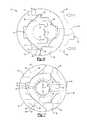
- FIG. 6is a plane view of the quick connector assembly showing the retaining member in the partially inserted position according to the subject invention.
- FIG. 7is a plane view of the quick connector assembly showing the retaining member in the fully inserted position according to the subject invention.
- a quick connector assembly 20 for securing an insertion member 22 within a receiving member 24 to convey fluids between the insertion member 22 and the receiving member 24is generally shown.
- the quick connector assembly 20includes an insertion member 22 that is axial inserted along a longitudinal axis A within an axial bore 26 of a receiving member 24 .
- a retaining member 28is disposed in the receiving member 24 for movement in a retaining slot 30 in a direction of insertion that is perpendicular to the longitudinal axis A.
- a positioning member 32is disposed in the axial bore 26 and includes a biasing portion 34 that extends angularly from a base portion 36 to a pair of blocking portions 38 .
- the blocking portions 38are movable between an extended position and a retracted position.
- the blocking portions 38are oriented opposite the direction of insertion of the retaining member 28 to block the retaining member 28 from moving into a fully inserted position when the biasing portion 34 is in the extended position.
- An annular collar 40 disposed on the insertion member 22engages the blocking portions 38 of the positioning member 32 when the insertion member 22 is axially inserted in the axial bore 26 to move the blocking portions 38 away from the retaining slot 30 and into the retracted position. As a result, the retaining member 28 is free to be moved into the fully inserted position to secure the insertion member 22 relative to receiving member 24 .
- the quick connector assembly 20includes a receiving member 24 having a plurality of cylindrical portions 42 , 44 , 46 that define an axial bore 26 that extends along a longitudinal axis A to receive the insertion member 22 within the axial bore 26 .
- the axial bore 26defines an annular groove 48 therein to receive an elastic O-ring 50 .
- the elastic O-ring 50is disposed in the annular groove 48 to engage the insertion member 22 and seal the insertion member 22 within the axial bore 26 .
- the receiving member 24extends between a receiving member top 52 and a receiving member bottom 54 .
- the receiving member 24is a female conduit member, and while the receiving member 24 may be any material known in the art, the receiving member 24 in the exemplary embodiment is a resin tube.
- the insertion member 22includes a shaft portion 56 that extends to a beveled end 58 .
- the insertion member 22is axially inserted into the receiving member top 52 for placement within the axial bore 26 of the receiving member 24 .
- the annular collar 40 of the insertion member 22is spaced from the beveled end 58 .
- the annular collar 40extends outwardly from the shaft portion 56 .
- the insertion member 22is a male conduit member, while the insertion member 22 may be any material known in the art.
- the insertion member 22 in the exemplary embodimentis a resin tube.
- the receiving member 24further includes a first cylindrical portion 42 that extends downwardly from the receiving member top 52 .
- a retaining slot 30is defined within the receiving member 24 to receive the retaining member 28 .
- the receiving member 24may be received in the retaining slot 30 in two positions, a partially inserted position and a fully inserted position.
- the partially inserted positionis where the retaining member 28 is partially inserted into the receiving member 24 to allow the insertion member 22 to be axially inserted into the axial bore 26 of the receiving member 24 .
- the fully inserted positionis where the retaining member 28 is fully inserted into the receiving member 24 to secure the insertion member 22 relative to the receiving member 24 .
- the retaining slot 30includes a retaining window 60 that extends through the first cylindrical portion 42 of the receiving member 24 and a pair of corresponding retaining arm receptacles 62 that extend through the first cylindrical portion 42 of the receiving member 24 oppositely from the retaining window 60 .
- the retaining window 60extends through the first cylindrical portion 42 and between a window top 64 and an axially spaced window bottom 66 .
- Each of the retaining arm receptacles 62extend through the first cylindrical portion 42 between a receptacle top 68 and an axially spaced receptacle bottom 70 .
- Each of the retaining arm receptacles 62further includes a receptacle edge 72 that extends axially between the receptacle top 68 and the receptacle bottom 70 .
- the receptacle edge 72engages the retaining member 28 to secure the retaining member 28 within retaining slot 30 when the retaining member 28 is in the fully inserted position relative to the receiving member 24 .
- a retaining notch 74is formed in the inner surface of the receiving member 24 adjacent the receiving member top 52 and between the retaining window 60 and each of the retaining arm receptacles 62 .
- the two retaining notches 74position the retaining member 28 in the partially inserted position relative to the receiving member 24 .
- the receiving member 24further includes a second cylindrical portion 44 that is continuous with the first cylindrical portion 42 .
- the second cylindrical portion 44extends downwardly from the first cylindrical portion 42 and has a diameter that is less than the diameter of the first cylindrical portion 42 .
- a nipple portion 46extends from the second cylindrical portion 44 to the receiving member bottom 54 .
- the nipple portion 46includes at least one annular ridge 76 that extends radially outwardly therefrom. While in the exemplary embodiment the nipple portion 46 extends straight downwardly, the nipple portion 46 may also include a bend.
- the nipple portion 46may include a 90 degree bend to connect the quick connector assembly 20 to other components in tightly spaced areas.
- the quick connector assembly 20further includes a retaining member 28 for insertion into the retaining slot 30 .
- the retaining member 28engages the insertion member 22 to secure the insertion member 22 within receiving member 24 .
- the retaining member 28is inserted between the window top 64 and the window bottom 66 of the retaining window 60 .
- the retaining member 28is guided through the receiving member 24 between the window top 64 and the window bottom 66 .
- the retaining member 28moves perpendicularly to the longitudinal axis A in a direction of insertion.
- the direction of insertion of the retaining member 28is the direction from the retaining window 60 towards the retaining arm receptacles 62 .
- the retaining member 28first moves perpendicularly to the longitudinal axis A to the partially inserted position to allow the insertion member 22 to be received within the receiving member 24 . Once the insertion member 22 has been axially inserted into the receiving member 24 , the retaining member 28 may be moved in the direction of insertion to the fully inserted position. In the fully inserted position, the retaining member 28 engages the insertion member 22 and secures the insertion member 22 relative to the receiving member 24 .
- the retaining member 28includes a retaining body portion 78 , a rib portion 80 and a pair of retaining arms 82 .
- the retaining body portion 78is inserted between the window top 64 and the window bottom 66 of the retaining window 60 and guided through the receiving member 24 between the window top 64 and the window bottom 66 .
- the axial spacing of the window top 64 and the window bottom 66 of the retaining window 60is configured as only slightly greater than the thickness of the retaining body portion 78 .
- the rib portion 80extends outwardly from the retaining body portion 78 and perpendicularly to the longitudinal axis A.
- the rib portion 80is shaped to correspond to the shape of the insertion member 22 , more specifically the shape of the shaft portion 56 and annular collar 40 of the insertion member 22 .
- the rib portion 80is U-shaped and has a curved surface that is substantially equal to the curvature of the shaft portion 56 of the insertion member 22 .
- the rib portion 80engages the annular collar 40 when the retaining member 28 is in the fully inserted position.
- the rib portion 80extends over the annular collar 40 to prevent the insertion member 22 from moving axially relative to the receiving member 24 .
- a pair of retaining arms 82extend outwardly from the retaining body portion 78 perpendicularly to the longitudinal axis A.
- the pair of retaining arms 82extend parallel to each other.
- the retaining arms 82engage the receiving member 24 to secure the retaining member 28 in either the partially inserted position or the fully inserted position.
- each of the retaining arms 82are moved in the direction of insertion to be received in a retaining arm receptacle 62 .
- the axial spacing of the receptacle top 68 and the receptacle bottom 70 of each of the retaining arm receptacles 62is configured as only slightly greater than the thickness of the retaining arm 82 received therein.
- the retaining body portion 78may include a pair of projecting portions 84 , with each of the projecting portions 84 extending from opposite sides of the retaining body portion 78 to extend outwardly away from each other. That is one of the projecting portions 84 disposed on one side of the retaining body portion 78 extends away from the other of the projecting portions 84 disposed on the opposite side of the retaining body portion 78 .
- the projecting portions 84engage the retaining window 60 as the retaining member 28 is inserted through the retaining window 60 to limit the movement of the retaining member 28 through the retaining window 60 .
- the projecting portions 84When the retaining member 28 is inserted in the direction of insertion, the projecting portions 84 will engage the retaining window 60 to stop the movement of the retaining member 28 in the direction of insertion.
- the projecting portions 84are positioned such that the movement in the direction of insertion will be stopped to correspond to the fully inserted position of the retaining member 28 .
- Each of the retaining arms 82include a barb 86 that extends outwardly away from the retaining arm 82 . That is one of the barbs 86 disposed on one of the retaining arms 82 extends away from the other of the barbs 86 disposed on the other of the retaining arms 82 .
- Each of the barbs 86may engage one of the receptacle edges 72 in the fully inserted position to secure the retaining member 28 within the receiving member 24 and secure the insertion member 22 to the receiving member 24 .
- each of the barbs 86may engage a respective one of the retaining notches 74 in the partially inserted position to temporarily secure the retaining member 28 within the receiving member 24 prior to the axial insertion of the insertion member 22 into the receiving member 24 .
- Each of the barbs 86includes in angled portion 88 disposed in the direction of insertion. This angled portion 88 allows the barbs 86 to be guided through the retaining slot 30 with minimal resistance.
- each of the barbs 86includes a flat portion 90 that is oriented opposite the direction of insertion. The flat portion 90 of the barb 86 engages one of the receptacle edges 72 when the retaining member 28 is in its fully inserted position. The positioning of the flat portion 90 against the receptacle edge 72 limits movement of the retaining member 28 in a direction opposite of insertion. Once the retaining member 28 has been inserted into the fully inserted position, the retaining member 28 is locked relative to the receiving member 24 . As such, a more secure connection is formed.
- the quick connector assembly 20further includes a positioning member 32 having a base portion 36 and a biasing portion 34 .
- the positioning member 32is a separate and distinct structure from the receiving member 24 and retaining member 28 . That is, the positioning member 32 is not unitary with either the receiving member 24 or the retaining member 28 .
- the biasing portion 34extends angularly from the base portion 36 to a pair of blocking portions 38 .
- the base portion 36is annular and disposed within the axial bore 26 of the receiving member 24 . Within the axial bore 26 , the base portion 36 is disposed above the O-ring 50 to sandwich the O-ring 50 between the positioning member 32 and the annular groove 48 .
- the shaft portion 56 of the insertion member 22is axially inserted through the annular base portion 36 .
- the biasing portion 34extends angularly from the top of the base portion 36 of the positioning member 32 and is moveable between an extended position and a retracted position. In the extended position, the biasing portion 34 blocks the retaining member 28 from being fully inserted into the retaining slot 30 of receiving member 24 . In the extended position, the blocking portions 38 of the biasing member are positioned to limit the movement of the retaining member 28 to only the partially inserted position. In the retracted position, the retaining member 28 is free to be moved to the fully inserted position. That is, the retaining member 28 is no longer blocked, thus enabling the retaining member 28 to be moved in the direction of insertion to the fully inserted position.
- the biasing portion 34is biased towards the receiving member top 52 of the receiving member 24 .
- the biasing portion 34extends to the pair of blocking portions 38 that are oriented opposite the direction of insertion of the retaining member 28 .
- the orientation of the blocking portions 38block the retaining member 28 from movement into the fully inserted position when the biasing portion 34 is in the extended position.
- the blocking portions 38are disposed in the axial bore 26 adjacent the window bottom 66 of the retaining slot 30 to block the movement of the retaining member 28 along the window bottom 66 and through the receiving member 24 .
- the insertion member 22is inserted into the axial bore 26 in a direction opposite the bias of the biasing portion 34 .
- the annular collar 40 of the insertion member 22engages the blocking portions 38 of the biasing portion 34 to move the blocking portions 38 away from the extended position to the retracted position.
- the retaining member 28may be moved into the fully inserted position relative to the receiving member 24 to engage the insertion member 22 and secure the insertion member 22 relative to the receiving member 24 .
Landscapes
- Engineering & Computer Science (AREA)
- General Engineering & Computer Science (AREA)
- Mechanical Engineering (AREA)
- Quick-Acting Or Multi-Walled Pipe Joints (AREA)
Abstract
Description
Claims (18)
Priority Applications (1)
| Application Number | Priority Date | Filing Date | Title |
|---|---|---|---|
| US13/031,846US8297659B2 (en) | 2011-02-22 | 2011-02-22 | Quick connector assembly |
Applications Claiming Priority (1)
| Application Number | Priority Date | Filing Date | Title |
|---|---|---|---|
| US13/031,846US8297659B2 (en) | 2011-02-22 | 2011-02-22 | Quick connector assembly |
Publications (2)
| Publication Number | Publication Date |
|---|---|
| US20120211977A1 US20120211977A1 (en) | 2012-08-23 |
| US8297659B2true US8297659B2 (en) | 2012-10-30 |
Family
ID=46652124
Family Applications (1)
| Application Number | Title | Priority Date | Filing Date |
|---|---|---|---|
| US13/031,846Active2031-04-29US8297659B2 (en) | 2011-02-22 | 2011-02-22 | Quick connector assembly |
Country Status (1)
| Country | Link |
|---|---|
| US (1) | US8297659B2 (en) |
Cited By (9)
| Publication number | Priority date | Publication date | Assignee | Title |
|---|---|---|---|---|
| US20160281894A1 (en)* | 2015-03-23 | 2016-09-29 | A. Kayser Automotive Systems Gmbh | Coupling Device |
| US9915388B2 (en)* | 2013-10-31 | 2018-03-13 | Sumitomo Riko Company Limited | Quick connector |
| US10006577B2 (en) | 2016-07-15 | 2018-06-26 | Miniature Precision Components, Inc. | Permanent quick connector and assembly therewith |
| US10422459B2 (en) | 2015-01-14 | 2019-09-24 | Norma U.S. Holding Llc | Conduit connector with a primary and secondary latch |
| US10865922B2 (en) | 2017-10-05 | 2020-12-15 | Novares Us Engine Components, Inc. | Anti-tamper permanent quick connect coupling device |
| US11035507B2 (en)* | 2017-02-28 | 2021-06-15 | Sanoh Industrial Co., Ltd. | Pipe connector |
| US11137094B2 (en)* | 2018-04-23 | 2021-10-05 | Reliance World Wide Corporation | Clip end device |
| USRE49411E1 (en) | 2015-11-20 | 2023-02-07 | A. Raymond Et Cie | Secure tube coupling with automatic connection |
| US12104729B2 (en) | 2022-08-30 | 2024-10-01 | A. Raymond Et Cie | Quick connector verification system and related method of use |
Families Citing this family (12)
| Publication number | Priority date | Publication date | Assignee | Title |
|---|---|---|---|---|
| JP5518522B2 (en)* | 2010-02-23 | 2014-06-11 | 株式会社ニフコ | connector |
| US9447905B2 (en)* | 2011-06-16 | 2016-09-20 | Togo Seisakusyo Corporation | Pipe connector |
| US9360143B2 (en)* | 2012-08-14 | 2016-06-07 | Mueller Industries, Inc. | Quick-connect assembly for a fluid valve |
| US9470351B2 (en) | 2013-03-11 | 2016-10-18 | Hanon Systems | Crimp fitting having reversed barbs |
| EP2796758B1 (en)* | 2013-04-23 | 2016-12-07 | TI Automotive (Fuldabrück) GmbH | Coupling |
| FR3021386B1 (en)* | 2014-05-22 | 2017-02-24 | A Raymond Et Cie | TUBULAR CONNECTION WITH AUTOMATIC CONNECTION |
| DE102018219932A1 (en)* | 2018-11-21 | 2020-05-28 | Fränkische Industrial Pipes GmbH & Co. KG | coupling |
| DE102018220521A1 (en) | 2018-11-28 | 2020-05-28 | Fränkische Industrial Pipes GmbH & Co. KG | Fluid connection |
| FR3106388B1 (en)* | 2020-01-20 | 2024-03-15 | A Raymond Et Cie | Device for connecting a tubular element |
| DE112021002981T5 (en)* | 2020-05-26 | 2023-03-09 | Dlhbowles, Inc. | QUICK CONNECTORS FOR FLUID LINES WITH POSITIVE CONFIRMATION FUNCTION |
| US11982382B2 (en)* | 2021-02-22 | 2024-05-14 | Cooper-Standard Automotive Inc. | Quick connector with bracket retainer |
| EP4473237A1 (en)* | 2022-02-01 | 2024-12-11 | Voss Automotive GmbH | Plug connector with mounting protection |
Citations (33)
| Publication number | Priority date | Publication date | Assignee | Title |
|---|---|---|---|---|
| US4943091A (en) | 1988-04-07 | 1990-07-24 | Proprietary Technology, Inc. | Quick connector |
| US4948176A (en) | 1987-09-14 | 1990-08-14 | Proprietary Technology, Inc. | Swivelable quick connector assembly |
| DE3924173A1 (en)* | 1989-07-21 | 1991-01-24 | Schaefer Stettiner Schrauben | Pipe connector with bore and sealing ring - has fastening bush fitting in bore and onto pipe end |
| US5112084A (en) | 1989-02-07 | 1992-05-12 | Usui Kokusai Sangyo Kaisha, Ltd. | Connector for small-diameter piping |
| US5161832A (en) | 1991-10-16 | 1992-11-10 | Huron Products Industries, Inc. | Plastic retainer for fluid coupling |
| US5161833A (en) | 1991-08-29 | 1992-11-10 | Huron Products Industries, Inc. | Positive transition quick connect coupling |
| US5297818A (en) | 1991-12-18 | 1994-03-29 | Itt Corporation | Retainer for pop-top indicator |
| US5324082A (en) | 1991-08-29 | 1994-06-28 | Bundy Corporation | Positive transition quick connect coupling |
| US5441313A (en) | 1994-01-18 | 1995-08-15 | Bundy Corporation | Insertion indicator for quick connector |
| US5499848A (en) | 1994-09-26 | 1996-03-19 | Bundy Corporation | Connection verifier for a quick connector coupling |
| US5551732A (en) | 1995-02-14 | 1996-09-03 | Proprietary Technology, Inc. | Quick connector |
| US5607190A (en) | 1994-03-04 | 1997-03-04 | Hutchinson | Quick and leaktight joining device for tubular pipes |
| US5626371A (en) | 1990-01-16 | 1997-05-06 | Bartholomew; Donald D. | Quick connector with one-piece retainer |
| US5785358A (en) | 1994-09-26 | 1998-07-28 | Bundy Corporation | Connection verifier for a quick connector coupling |
| US6089616A (en) | 1996-06-20 | 2000-07-18 | A. Raymond & Cie | Releasable plug connector with fitting indicator |
| US6129393A (en) | 1997-11-11 | 2000-10-10 | Tokai Rubber Industries, Ltd | Quick connector assembly |
| US6173998B1 (en) | 1998-07-16 | 2001-01-16 | Rasmussen Gmbh | Plug-in coupling for connecting two fluid conduits |
| US6186561B1 (en) | 1996-06-07 | 2001-02-13 | Sanoh Kogyo Kabushiki Kaisha | Retainer for piping connector |
| US6250692B1 (en) | 1998-07-09 | 2001-06-26 | Tokai Rubber Industries, Ltd. | Quick connector assembly, and female member of quick connector assembly |
| US6328344B1 (en)* | 1998-09-17 | 2001-12-11 | Togo Seisakusyo Corporation | Pipe fitting with improved fitting checker |
| US6402204B1 (en) | 1999-11-03 | 2002-06-11 | Itt Manufacturing Enterprises, Inc. | Quick connect retainer with recessed latch finger |
| US6428055B1 (en) | 1998-03-05 | 2002-08-06 | A. Raymond & Cie | Releasable quick coupling for metal pipes |
| US6543814B2 (en) | 2000-08-10 | 2003-04-08 | John M. Bartholomew | Quick connector |
| US6851721B2 (en) | 2000-12-22 | 2005-02-08 | Legris Sa | Fast coupler with connection indicator |
| US20050236833A1 (en)* | 2004-04-23 | 2005-10-27 | Poirier David M | Tube lock quick connector |
| US6971684B2 (en) | 2002-06-24 | 2005-12-06 | Ferrari Group Srl | Fast coupling for irrigation systems, particularly domestic irrigation systems |
| US20060082145A1 (en)* | 2004-10-15 | 2006-04-20 | Itt Manufacturing Enterprises, Inc. | Quick connector with disk retention retainer |
| US20070200339A1 (en) | 2003-12-22 | 2007-08-30 | Katsuichi Yagisawa | Resin Tube-Equipped Quick Connector |
| US20080007053A1 (en)* | 2005-05-03 | 2008-01-10 | Ti Group Automotive Systems, Llc | Redundant latch/verifier for a quick connector |
| US7344166B2 (en) | 2004-02-05 | 2008-03-18 | Ti Group Automotive Systems, Llc | Quick connector for high pressure applications |
| US7455327B2 (en) | 2004-12-23 | 2008-11-25 | Frankische Rohrwerke Gebr. Kirchner Gmbh & Co. Kg | Coupling device |
| US20100032937A1 (en)* | 2008-08-07 | 2010-02-11 | Ti Group Automotive Systems, Inc. | Quick connector coupling with pull tab verifier |
| US20100276924A1 (en)* | 2009-04-30 | 2010-11-04 | Hutchinson | Snap-on coupling for connecting a fluid pipe to a rigid end fitting with a connection indicator and method of inspecting this connection |
- 2011
- 2011-02-22USUS13/031,846patent/US8297659B2/enactiveActive
Patent Citations (33)
| Publication number | Priority date | Publication date | Assignee | Title |
|---|---|---|---|---|
| US4948176A (en) | 1987-09-14 | 1990-08-14 | Proprietary Technology, Inc. | Swivelable quick connector assembly |
| US4943091A (en) | 1988-04-07 | 1990-07-24 | Proprietary Technology, Inc. | Quick connector |
| US5112084A (en) | 1989-02-07 | 1992-05-12 | Usui Kokusai Sangyo Kaisha, Ltd. | Connector for small-diameter piping |
| DE3924173A1 (en)* | 1989-07-21 | 1991-01-24 | Schaefer Stettiner Schrauben | Pipe connector with bore and sealing ring - has fastening bush fitting in bore and onto pipe end |
| US5626371A (en) | 1990-01-16 | 1997-05-06 | Bartholomew; Donald D. | Quick connector with one-piece retainer |
| US5324082A (en) | 1991-08-29 | 1994-06-28 | Bundy Corporation | Positive transition quick connect coupling |
| US5161833A (en) | 1991-08-29 | 1992-11-10 | Huron Products Industries, Inc. | Positive transition quick connect coupling |
| US5161832A (en) | 1991-10-16 | 1992-11-10 | Huron Products Industries, Inc. | Plastic retainer for fluid coupling |
| US5297818A (en) | 1991-12-18 | 1994-03-29 | Itt Corporation | Retainer for pop-top indicator |
| US5441313A (en) | 1994-01-18 | 1995-08-15 | Bundy Corporation | Insertion indicator for quick connector |
| US5607190A (en) | 1994-03-04 | 1997-03-04 | Hutchinson | Quick and leaktight joining device for tubular pipes |
| US5499848A (en) | 1994-09-26 | 1996-03-19 | Bundy Corporation | Connection verifier for a quick connector coupling |
| US5785358A (en) | 1994-09-26 | 1998-07-28 | Bundy Corporation | Connection verifier for a quick connector coupling |
| US5551732A (en) | 1995-02-14 | 1996-09-03 | Proprietary Technology, Inc. | Quick connector |
| US6186561B1 (en) | 1996-06-07 | 2001-02-13 | Sanoh Kogyo Kabushiki Kaisha | Retainer for piping connector |
| US6089616A (en) | 1996-06-20 | 2000-07-18 | A. Raymond & Cie | Releasable plug connector with fitting indicator |
| US6129393A (en) | 1997-11-11 | 2000-10-10 | Tokai Rubber Industries, Ltd | Quick connector assembly |
| US6428055B1 (en) | 1998-03-05 | 2002-08-06 | A. Raymond & Cie | Releasable quick coupling for metal pipes |
| US6250692B1 (en) | 1998-07-09 | 2001-06-26 | Tokai Rubber Industries, Ltd. | Quick connector assembly, and female member of quick connector assembly |
| US6173998B1 (en) | 1998-07-16 | 2001-01-16 | Rasmussen Gmbh | Plug-in coupling for connecting two fluid conduits |
| US6328344B1 (en)* | 1998-09-17 | 2001-12-11 | Togo Seisakusyo Corporation | Pipe fitting with improved fitting checker |
| US6402204B1 (en) | 1999-11-03 | 2002-06-11 | Itt Manufacturing Enterprises, Inc. | Quick connect retainer with recessed latch finger |
| US6543814B2 (en) | 2000-08-10 | 2003-04-08 | John M. Bartholomew | Quick connector |
| US6851721B2 (en) | 2000-12-22 | 2005-02-08 | Legris Sa | Fast coupler with connection indicator |
| US6971684B2 (en) | 2002-06-24 | 2005-12-06 | Ferrari Group Srl | Fast coupling for irrigation systems, particularly domestic irrigation systems |
| US20070200339A1 (en) | 2003-12-22 | 2007-08-30 | Katsuichi Yagisawa | Resin Tube-Equipped Quick Connector |
| US7344166B2 (en) | 2004-02-05 | 2008-03-18 | Ti Group Automotive Systems, Llc | Quick connector for high pressure applications |
| US20050236833A1 (en)* | 2004-04-23 | 2005-10-27 | Poirier David M | Tube lock quick connector |
| US20060082145A1 (en)* | 2004-10-15 | 2006-04-20 | Itt Manufacturing Enterprises, Inc. | Quick connector with disk retention retainer |
| US7455327B2 (en) | 2004-12-23 | 2008-11-25 | Frankische Rohrwerke Gebr. Kirchner Gmbh & Co. Kg | Coupling device |
| US20080007053A1 (en)* | 2005-05-03 | 2008-01-10 | Ti Group Automotive Systems, Llc | Redundant latch/verifier for a quick connector |
| US20100032937A1 (en)* | 2008-08-07 | 2010-02-11 | Ti Group Automotive Systems, Inc. | Quick connector coupling with pull tab verifier |
| US20100276924A1 (en)* | 2009-04-30 | 2010-11-04 | Hutchinson | Snap-on coupling for connecting a fluid pipe to a rigid end fitting with a connection indicator and method of inspecting this connection |
Cited By (11)
| Publication number | Priority date | Publication date | Assignee | Title |
|---|---|---|---|---|
| US9915388B2 (en)* | 2013-10-31 | 2018-03-13 | Sumitomo Riko Company Limited | Quick connector |
| US10422459B2 (en) | 2015-01-14 | 2019-09-24 | Norma U.S. Holding Llc | Conduit connector with a primary and secondary latch |
| US20160281894A1 (en)* | 2015-03-23 | 2016-09-29 | A. Kayser Automotive Systems Gmbh | Coupling Device |
| US9739403B2 (en)* | 2015-03-23 | 2017-08-22 | A. Kayser Automotive Systems Gmbh | Coupling device |
| USRE49411E1 (en) | 2015-11-20 | 2023-02-07 | A. Raymond Et Cie | Secure tube coupling with automatic connection |
| US10006577B2 (en) | 2016-07-15 | 2018-06-26 | Miniature Precision Components, Inc. | Permanent quick connector and assembly therewith |
| US10480699B2 (en) | 2016-07-15 | 2019-11-19 | Miniature Precision Components, Inc. | Permanent quick connector and assembly therewith |
| US11035507B2 (en)* | 2017-02-28 | 2021-06-15 | Sanoh Industrial Co., Ltd. | Pipe connector |
| US10865922B2 (en) | 2017-10-05 | 2020-12-15 | Novares Us Engine Components, Inc. | Anti-tamper permanent quick connect coupling device |
| US11137094B2 (en)* | 2018-04-23 | 2021-10-05 | Reliance World Wide Corporation | Clip end device |
| US12104729B2 (en) | 2022-08-30 | 2024-10-01 | A. Raymond Et Cie | Quick connector verification system and related method of use |
Also Published As
| Publication number | Publication date |
|---|---|
| US20120211977A1 (en) | 2012-08-23 |
Similar Documents
| Publication | Publication Date | Title |
|---|---|---|
| US8297659B2 (en) | Quick connector assembly | |
| US5542716A (en) | Quick connector with snap-on retainer | |
| US6634679B1 (en) | Fluid quick connector with retention clip for flangeless endforms | |
| US20150159792A1 (en) | Self-locking push-to-connect insert | |
| US6905143B2 (en) | Fluid conduit quick connector and stuffer pack | |
| US8534711B2 (en) | Piping unit for transporting fuel | |
| CN104279103B (en) | Fuel injection assemblies for combustion engine | |
| CN108138999B (en) | Block fitting and seal structure | |
| CN106062356B (en) | Fuel injection assembly | |
| CN107588256B (en) | Plastic sealing fitting | |
| US20030092324A1 (en) | Electrical contact for fluid quick connectors | |
| US20060082145A1 (en) | Quick connector with disk retention retainer | |
| EP3803183B1 (en) | Quick connector | |
| CN105579699A (en) | Attachment structure of nozzle plate for fuel injection device | |
| RU2692852C2 (en) | Pipeline assembly with connector | |
| CN111076010A (en) | Quick connect apparatus for fluid transport | |
| US20030090109A1 (en) | Fluid quick connector with secure electrical contact | |
| US7055869B2 (en) | False insertion protection top hat for fluid quick connectors | |
| US10612707B2 (en) | Quick connect assembly and method | |
| CN100402911C (en) | Piping unit for transporting fuel | |
| JP2004256080A (en) | Antistatic tool for piping | |
| CN112601674B (en) | Assembly for a fluid storage tank comprising a baffle and a fluid delivery line passing through the baffle | |
| US6755675B2 (en) | Fluid quick connector with secure electrical ground contact | |
| US20070126232A1 (en) | Fluid coupling with non-protective coated endform tip | |
| US10948114B2 (en) | Connector for fluidic connection between two hoses or the like and arrangement associated |
Legal Events
| Date | Code | Title | Description |
|---|---|---|---|
| AS | Assignment | Owner name:JPMORGAN CHASE BANK, N.A., ILLINOIS Free format text:SECURITY AGREEMENT;ASSIGNOR:MINIATURE PRECISION COMPONENTS, INC.;REEL/FRAME:026746/0547 Effective date:20110805 | |
| AS | Assignment | Owner name:MINIATURE PRECISION COMPONENTS, INC., WISCONSIN Free format text:ASSIGNMENT OF ASSIGNORS INTEREST;ASSIGNORS:CALLAHAN, DOUGLAS JOHN;PRUZINSKIS, JURIS JULIJS;MIXTER, STEVE;AND OTHERS;SIGNING DATES FROM 20120207 TO 20120214;REEL/FRAME:027732/0945 | |
| STCF | Information on status: patent grant | Free format text:PATENTED CASE | |
| REMI | Maintenance fee reminder mailed | ||
| FPAY | Fee payment | Year of fee payment:4 | |
| SULP | Surcharge for late payment | ||
| MAFP | Maintenance fee payment | Free format text:PAYMENT OF MAINTENANCE FEE, 8TH YR, SMALL ENTITY (ORIGINAL EVENT CODE: M2552); ENTITY STATUS OF PATENT OWNER: SMALL ENTITY Year of fee payment:8 | |
| AS | Assignment | Owner name:NOVARES US ENGINE COMPONENTS, INC., WISCONSIN Free format text:CHANGE OF NAME;ASSIGNOR:MINIATURE PRECISION COMPONENTS, INC.;REEL/FRAME:053668/0992 Effective date:20190930 | |
| MAFP | Maintenance fee payment | Free format text:PAYMENT OF MAINTENANCE FEE, 12TH YR, SMALL ENTITY (ORIGINAL EVENT CODE: M2553); ENTITY STATUS OF PATENT OWNER: SMALL ENTITY Year of fee payment:12 |