US8297469B1 - Protective sleeve device for vials - Google Patents
Protective sleeve device for vialsDownload PDFInfo
- Publication number
- US8297469B1 US8297469B1US13/189,310US201113189310AUS8297469B1US 8297469 B1US8297469 B1US 8297469B1US 201113189310 AUS201113189310 AUS 201113189310AUS 8297469 B1US8297469 B1US 8297469B1
- Authority
- US
- United States
- Prior art keywords
- housing
- inner cavity
- angle
- side wall
- vial
- Prior art date
- Legal status (The legal status is an assumption and is not a legal conclusion. Google has not performed a legal analysis and makes no representation as to the accuracy of the status listed.)
- Expired - Fee Related
Links
Images


Classifications
- A—HUMAN NECESSITIES
- A61—MEDICAL OR VETERINARY SCIENCE; HYGIENE
- A61J—CONTAINERS SPECIALLY ADAPTED FOR MEDICAL OR PHARMACEUTICAL PURPOSES; DEVICES OR METHODS SPECIALLY ADAPTED FOR BRINGING PHARMACEUTICAL PRODUCTS INTO PARTICULAR PHYSICAL OR ADMINISTERING FORMS; DEVICES FOR ADMINISTERING FOOD OR MEDICINES ORALLY; BABY COMFORTERS; DEVICES FOR RECEIVING SPITTLE
- A61J1/00—Containers specially adapted for medical or pharmaceutical purposes
- A61J1/14—Details; Accessories therefor
- A61J1/16—Holders for containers
- A—HUMAN NECESSITIES
- A61—MEDICAL OR VETERINARY SCIENCE; HYGIENE
- A61J—CONTAINERS SPECIALLY ADAPTED FOR MEDICAL OR PHARMACEUTICAL PURPOSES; DEVICES OR METHODS SPECIALLY ADAPTED FOR BRINGING PHARMACEUTICAL PRODUCTS INTO PARTICULAR PHYSICAL OR ADMINISTERING FORMS; DEVICES FOR ADMINISTERING FOOD OR MEDICINES ORALLY; BABY COMFORTERS; DEVICES FOR RECEIVING SPITTLE
- A61J1/00—Containers specially adapted for medical or pharmaceutical purposes
- A61J1/05—Containers specially adapted for medical or pharmaceutical purposes for collecting, storing or administering blood, plasma or medical fluids ; Infusion or perfusion containers
- A61J1/06—Ampoules or carpules
- A61J1/065—Rigid ampoules, e.g. glass ampoules
- B—PERFORMING OPERATIONS; TRANSPORTING
- B65—CONVEYING; PACKING; STORING; HANDLING THIN OR FILAMENTARY MATERIAL
- B65D—CONTAINERS FOR STORAGE OR TRANSPORT OF ARTICLES OR MATERIALS, e.g. BAGS, BARRELS, BOTTLES, BOXES, CANS, CARTONS, CRATES, DRUMS, JARS, TANKS, HOPPERS, FORWARDING CONTAINERS; ACCESSORIES, CLOSURES, OR FITTINGS THEREFOR; PACKAGING ELEMENTS; PACKAGES
- B65D2303/00—Orienting or positioning means for containers
- F—MECHANICAL ENGINEERING; LIGHTING; HEATING; WEAPONS; BLASTING
- F25—REFRIGERATION OR COOLING; COMBINED HEATING AND REFRIGERATION SYSTEMS; HEAT PUMP SYSTEMS; MANUFACTURE OR STORAGE OF ICE; LIQUEFACTION SOLIDIFICATION OF GASES
- F25D—REFRIGERATORS; COLD ROOMS; ICE-BOXES; COOLING OR FREEZING APPARATUS NOT OTHERWISE PROVIDED FOR
- F25D2303/00—Details of devices using other cold materials; Details of devices using cold-storage bodies
- F25D2303/08—Devices using cold storage material, i.e. ice or other freezable liquid
- F25D2303/083—Devices using cold storage material, i.e. ice or other freezable liquid using cold storage material disposed in closed wall forming part of a container for products to be cooled
- F—MECHANICAL ENGINEERING; LIGHTING; HEATING; WEAPONS; BLASTING
- F25—REFRIGERATION OR COOLING; COMBINED HEATING AND REFRIGERATION SYSTEMS; HEAT PUMP SYSTEMS; MANUFACTURE OR STORAGE OF ICE; LIQUEFACTION SOLIDIFICATION OF GASES
- F25D—REFRIGERATORS; COLD ROOMS; ICE-BOXES; COOLING OR FREEZING APPARATUS NOT OTHERWISE PROVIDED FOR
- F25D2331/00—Details or arrangements of other cooling or freezing apparatus not provided for in other groups of this subclass
- F25D2331/80—Type of cooled receptacles
- F25D2331/803—Bottles
- F—MECHANICAL ENGINEERING; LIGHTING; HEATING; WEAPONS; BLASTING
- F25—REFRIGERATION OR COOLING; COMBINED HEATING AND REFRIGERATION SYSTEMS; HEAT PUMP SYSTEMS; MANUFACTURE OR STORAGE OF ICE; LIQUEFACTION SOLIDIFICATION OF GASES
- F25D—REFRIGERATORS; COLD ROOMS; ICE-BOXES; COOLING OR FREEZING APPARATUS NOT OTHERWISE PROVIDED FOR
- F25D2331/00—Details or arrangements of other cooling or freezing apparatus not provided for in other groups of this subclass
- F25D2331/80—Type of cooled receptacles
- F25D2331/809—Holders
- F—MECHANICAL ENGINEERING; LIGHTING; HEATING; WEAPONS; BLASTING
- F25—REFRIGERATION OR COOLING; COMBINED HEATING AND REFRIGERATION SYSTEMS; HEAT PUMP SYSTEMS; MANUFACTURE OR STORAGE OF ICE; LIQUEFACTION SOLIDIFICATION OF GASES
- F25D—REFRIGERATORS; COLD ROOMS; ICE-BOXES; COOLING OR FREEZING APPARATUS NOT OTHERWISE PROVIDED FOR
- F25D3/00—Devices using other cold materials; Devices using cold-storage bodies
- F25D3/02—Devices using other cold materials; Devices using cold-storage bodies using ice, e.g. ice-boxes
- F25D3/06—Movable containers
- F25D3/08—Movable containers portable, i.e. adapted to be carried personally
Definitions
- the present inventionis directed to a protective device for protecting a vial such as a vial of insulin.
- the present inventionfeatures a protective sleeve system for protecting a vial.
- the system of the present inventionmay help a user transport his/her vials more easily and safely.
- the system of the present inventionmay also help keep the contents of the vial cool.
- the protective sleeve systemcomprises a housing having side wall, a top, a top edge, a bottom surface, and an inner cavity, the inner cavity is adapted to temporarily hold a vial, the top of the housing is at an angle with respect to the side wall of the housing such that a top crater is formed; an aperture providing access to the inner cavity of the housing such that a vial can be inserted into the inner cavity of the housing, the aperture is disposed in the top of the housing at a narrowest part of the top crater; a first window and a second window each disposed in the side wall of the housing, the windows provide access to the inner cavity of the housing, the first window is positioned opposite the second window; and a drainage hole disposed in the bottom surface of the housing and fluidly connected to the inner cavity of the housing, the drainage hole allows a liquid to drain from the inner cavity of the housing.
- the housingis cylindrical-shaped, cuboidal-shaped, or geometric prism-shaped.
- the inner cavityis cylindrical in shape.
- the windowsare positioned near the top edge of the housing.
- the angleis between about 10 to 80 degrees.
- the bottom surface of the housingis at an angle with respect to the side wall of the housing forming a bottom crater, wherein the drainage hole is positioned at a narrowest part of the bottom crater.
- the systemfurther comprises a cooling element disposed in the side wall of the housing.
- the cooling elementis constructed from a material comprising a cellulose, hydroxyethyl cellulose, sodium chloride, water, ammonium chloride, urea, or a combination thereof.
- the systemfurther comprises a label indentation disposed in the side wall of the housing, the label indentation is adapted to receive a label.
- the systemfurther comprises a weight disposed in the housing at or near the bottom surface of the housing. In some embodiments, the weight surrounds the bottom crater. In some embodiments, the weight surrounds the drainage hole. In some embodiments, the system further comprises a strap having a first end and a second end, the first end is attached to the side wall of the housing in a first position and the second end is attached to the side wall of the housing in a second position. In some embodiments, the first end is removably attached to the side wall of the housing. In some embodiments, the first position is opposite the second position. In some embodiments, a strap aperture is disposed in the strap.
- the systemfurther comprises a lid removably attached to the housing, wherein the lid can move between at least an open position and a closed position respectively allowing and preventing access to the inner cavity.
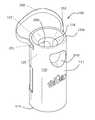
- FIG. 1is a perspective view of the system of the present invention.
- FIG. 2is an exploded view of the system of the present invention.
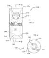
- FIG. 3is a side in-use view of the system of the present invention.
- FIG. 4is a bottom view of the system of the present invention.
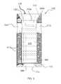
- FIG. 5is a side cross-sectional view of the system of the present invention.
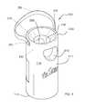
- FIG. 6is a perspective view of the system of the present invention, wherein a strap covers the top of the housing.
- the present inventionfeatures a protective sleeve system 100 for a vial 210 (e.g., an insulin vial).
- the system 100comprises a housing 110 having side wall 115 (e.g., with a front surface 111 and a back surface 112 ), a top 113 , a bottom surface 114 , and an inner cavity 120 .
- the inner cavity 120is adapted to temporarily hold a vial 210 (e.g., snugly hold the vial 210 ).
- the housing 110may be constructed in a variety of shapes, e.g., cylindrical-shaped, cuboidal-shaped, geometric prism-shaped such as triangular prism-shaped, hexagonal prism-shaped, etc.
- the housing 110is not limited to the aforementioned shapes.
- the inner cavity 120is generally cylindrical so as to hold a vial 210 .
- An aperture 118is disposed in the top 113 of the housing 110 .
- the aperture 118provides access to the inner cavity 120 of the housing 110 .
- a vial 210can be inserted into the inner cavity 120 via the aperture 118 .
- the top 113 of the housing 110is beveled, for example the top 113 of the housing 113 is at an angle 102 with respect to the side wall 115 of the housing 110 (angle 102 is shown in FIG. 5 ).
- a top edge 113 ais formed between the side wall 115 of the housing 110 and the top 113 of the housing 110 .
- the position of the aperture 118is lower (e.g., closer to the bottom surface 114 of the housing 110 ) than the position of the top edge 113 a of the housing 110 .
- This configurationforms a top crater 119 at the top of the housing 110 (e.g., see FIG. 5 ).
- the aperture 118is positioned at the narrower part of the top crater 119 .
- the top crater 119has a trapezoidal shape as viewed from the side.
- the top crater 119 formed from the top 113 of the housing 110 and the top edge 113 of the housing 110provides a user ample room to access the top 210 a of the vial 210 .
- the angle 102is between about 5 to 10 degrees. In some embodiments, the angle 102 is between about 10 to 20 degrees. In some embodiments, the angle 102 is between about 20 to 30 degrees, in some embodiments, the angle 102 is between about 30 to 40 degrees. In some embodiments, the angle 102 is between about 40 to 50 degrees. In some embodiments, the angle 102 is between about 50 to 60 degrees. In some embodiments, the angle 102 is between about 60 to 70 degrees. In some embodiments, the angle 102 is between about 70 to 80 degrees. In some embodiments, the angle 102 is between about 5 to 20 degrees. In some embodiments, the angle 102 is between about 5 to 30 degrees. In some embodiments, the angle 102 is between about 10 to 30 degrees.
- the angle 102is between about 10 to 40 degrees. In some embodiments, the angle 102 is between about 10 to 50 degrees. In some embodiments, the angle 102 is between about 20 to 40 degrees. In some embodiments, the angle 102 is between about 20 to 50 degrees. In some embodiments, the angle 102 is between about 20 to 60 degrees. In some embodiments, the angle 102 is between about 20 to 70 degrees. In some embodiments, the angle 102 is between about 10 to 60 degrees. In some embodiments, the angle 102 is between about 10 to 70 degrees. In some embodiments, the angle 102 is between about 10 to 80 degrees. In some embodiments, the angle 102 is between about 20 to 80 degrees. In some embodiments, the angle 102 is between about 30 to 60 degrees.
- the angle 102is between about 30 to 70 degrees. In some embodiments, the angle 102 is between about 30 to 80 degrees. In some embodiments, the angle 102 is between about 40 to 60 degrees. In some embodiments, the angle 102 is between about 40 to 70 degrees. In some embodiments, the angle 102 is between about 40 to 80 degrees. In some embodiments, the angle 102 is between about 50 to 70 degrees. In some embodiments, the angle 102 is between about 50 to 80 degrees. In some embodiments, the angle 102 is between about 60 to 80 degrees.
- a first window 310is disposed in the side wall 115 of the housing 110 , e.g., in the front surface 111 .
- a second window 320is disposed in the side wall 115 of the housing 110 , e.g., in the back surface 112 .
- the front surface 111is opposite the back surface 112 .
- the first window 310 and/or second window 320may help a user remove a vial 210 from the inner cavity 120 of the housing 110 .
- the windows 310 , 320may allow a user to grasp the vial 210 while it is in the inner cavity 120 (e.g., an ultimately pull upwardly on the vial 210 ).
- the windows 310 , 320help a user view the contents of the vial 210 .
- the windows 310 , 320can help a user view a needle being inserted into the vial 210 (e.g., into the top 210 a of the vial 210 ).
- the windows 310 , 320are positioned near the top edge 113 a of the housing 110 , e.g., just below the top crater 119 , e.g., just below the aperture 118 .
- FIG. 5shows the position of the windows 310 , 320 wherein the windows 310 , 320 allow a user to see the top 210 a of the vial 210 .
- the height of the housing 110is measured from the top edge 113 a to the bottom edge 114 a .
- the windows 310 , 320may be positioned in the top half of the height of the housing 110 , the top half being the half including the top edge 113 a of the housing 110 .
- the windows 310 , 320may be constructed in any shape (e.g., circular, rectangular, triangular, irregular in shape, etc.).
- the windows 310 , 320may be constructed in any size.
- the inner cavity 120is adapted to hold (e.g., snugly hold) a vial 210 .
- the outer surface 215 of the vial 210rests against the inner walls of the inner cavity 120 .
- the vial 210can be inserted into the inner cavity 120 via the aperture 118 at the bottom of the crater 119 formed from the angled top 113 of the housing 110 .
- Condensationmay collect in the inner cavity 120 of the housing 110 .
- a drainage hole 160is disposed in the bottom surface 114 of the housing 110 .
- the drainage hole 160allows for condensation to drain from the inner cavity 120 .
- the drainage hole 160may also be used to help a user remove the vial 210 from the inner cavity 120 . For example, a user can push his/her finger through the drainage hole 160 so as to push the vial 210 out of the aperture 118 in the top 113 of the housing 110 .
- a bottom crater 189is formed in the bottom surface 114 of the housing 110 (similar to the top crater 119 ), wherein the bottom surface 114 of the housing 110 is at an angle 103 with respect to the side wall 115 of the housing 110 .
- the drainage hole 160is positioned at the narrower part of the bottom crater 189 (e.g., see FIG. 3 , FIG. 5 ).
- FIG. 5shows the angle 103 .
- Angle 103refers to the angle between the bottom surface 114 of the housing 110 (the angled portion) and the side wall 115 (as opposed to the bottom surface 114 and the bottom edge 114 a ).
- a label indentation 158is disposed in the side wall 115 (e.g., the front surface 111 , the back surface 112 , etc.) of the housing 110 .
- the label indentation 158is adapted to receive a label 159 (see FIG. 2 ).
- the label 159may provide information about the user and/or about the contents of the vial 210 , for example.
- a cooling element 410is disposed in the housing 110 (e.g., in the side wall 115 of the housing 110 ).
- the cooling element 410is designed to help chill the contents of the inner cavity 120 , for example the vial 210 .
- a usercan place the system 100 in a freezer or a refrigerator so as to chill the cooling element 410 .
- the chilled cooling element 410may help to keep the vial 210 cold.
- the cooling element 410may comprise a gel.
- the cooling element 410comprises cellulose, hydroxyethyl cellulose, sodium chloride, water, ammonium chloride, urea, the like, or a combination thereof.
- the cooling element 410is not limited to the aforementioned materials.
- the system 100further comprises a strap 250 attached to the housing 110 .
- the strap 250has a first end 251 and a second end 252 .
- the first end 151is attached to the side wall 115 of the housing 110 in a first position
- the second end 252is attached to the side wall 115 of the housing 110 in a second position.
- the first positionis opposite the second position.
- the first position and/or the second positionare near the top edge 113 of the housing 110 .
- the strap 250is for helping to secure a vial 210 inside the inner cavity 120 .
- the strap 250is for helping to carry the housing 110 .
- the strap 250is removable. As shown in FIG.
- a strap aperture 253(e.g., a hole in the strap 250 ) is disposed in the strap 250 .
- the strap aperture 253may help to provide a user access to the contents of the vial 210 while the strap 250 secures the vial 210 in the housing 110 .
- the system 100further comprises a lid 140 .
- the lid 140may be removably attached to the housing 110 (e.g., at the top edge 113 ).
- the lid 140is pivotally attached to the housing 110 (e.g., the lid 140 is attached on one end to the housing 110 ).
- the lid 140can move between at least an open position and a closed position respectively allowing and preventing access to the top crater 119 and/or inner cavity 120 and/or vial 210
- the lid 140can be secured in the closed position via a securing means (e.g., a snap mechanism, a buckle mechanism, a magnet mechanism, a hook-and-loop fastener mechanism, a clip mechanism, a hook mechanism, the like, a combination thereof).
- a securing meanse.g., a snap mechanism, a buckle mechanism, a magnet mechanism, a hook-and-loop fastener mechanism, a clip mechanism, a hook mechanism, the like, a combination thereof.
- the system 100 of the present inventionmay be constructed from a variety of materials.
- the housing 110is constructed from a soft and protective material (e.g., foam).
- the housing 110is constructed with an injection foam molding manufacturing process or any other appropriate manufacturing process.
- the housing 110can float.
- the system 100is reusable.
- the system 100 of the present inventionmay be constructed in a variety of shapes, sizes, styles, designs, and/or colors.
- the housing 110is between about 1 to 2 inches in height as measured from the bottom edge 114 a to the top edge 113 a .
- the housing 110is between about 2 to 3 inches in height as measured from the bottom edge 114 a to the top edge 113 a .
- the housing 110is between about 3 to 4 inches in height as measured from the bottom edge 114 a to the top edge 113 a .
- the present inventionis not limited to the aforementioned dimensions.
- the term “about”refers to plus or minus 10% of the referenced number.
- an embodiment wherein the housing 110 is about 4 inches in heightincludes a housing 110 that is between 3.6 and 4.4 inches in height.
- the angle 103is between about 5 to 10 degrees. In some embodiments, the angle 103 is between about 10 to 20 degrees. In some embodiments, the angle 103 is between about 20 to 30 degrees. In some embodiments, the angle 103 is between about 30 to 40 degrees. In some embodiments, the angle 103 is between about 40 to 50 degrees. In some embodiments, the angle 103 is between about 50 to 60 degrees. In some embodiments, the angle 103 is between about 60 to 70 degrees. In some embodiments, the angle 103 is between about 70 to 80 degrees. In some embodiments, the angle 103 is between about 5 to 20 degrees. In some embodiments, the angle 103 is between about 5 to 30 degrees. In some embodiments, the angle 103 is between about 10 to 30 degrees.
- the angle 103is between about 10 to 40 degrees. In some embodiments, the angle 103 is between about 10 to 50 degrees. In some embodiments, the angle 103 is between about 20 to 40 degrees. In some embodiments, the angle 103 is between about 20 to 50 degrees. In some embodiments, the angle 103 is between about 20 to 60 degrees. In some embodiments, the angle 103 is between about 20 to 70 degrees. In some embodiments, the angle 103 is between about 10 to 60 degrees. In some embodiments, the angle 103 is between about 10 to 70 degrees. In some embodiments, the angle 103 is between about 10 to 80 degrees. In some embodiments, the angle 103 is between about 20 to 80 degrees. In some embodiments, the angle 103 is between about 30 to 60 degrees.
- the angle 103is between about 30 to 70 degrees. In some embodiments, the angle 103 is between about 30 to 80 degrees. In some embodiments, the angle 103 is between about 40 to 60 degrees. In some embodiments, the angle 103 is between about 40 to 70 degrees. In some embodiments, the angle 103 is between about 40 to 80 degrees. In some embodiments, the angle 103 is between about 50 to 70 degrees. In some embodiments, the angle 103 is between about 50 to 80 degrees. In some embodiments, the angle 103 is between about 60 to 80 degrees.
Landscapes
- Health & Medical Sciences (AREA)
- Pharmacology & Pharmacy (AREA)
- Life Sciences & Earth Sciences (AREA)
- Animal Behavior & Ethology (AREA)
- General Health & Medical Sciences (AREA)
- Public Health (AREA)
- Veterinary Medicine (AREA)
- Medical Preparation Storing Or Oral Administration Devices (AREA)
- Details Of Rigid Or Semi-Rigid Containers (AREA)
Abstract
Description
Claims (14)
Priority Applications (2)
| Application Number | Priority Date | Filing Date | Title |
|---|---|---|---|
| US13/189,310US8297469B1 (en) | 2009-02-26 | 2011-07-22 | Protective sleeve device for vials |
| US13/630,216US8678229B1 (en) | 2009-02-26 | 2012-09-28 | Protective sleeve system for vials |
Applications Claiming Priority (2)
| Application Number | Priority Date | Filing Date | Title |
|---|---|---|---|
| US39388209A | 2009-02-26 | 2009-02-26 | |
| US13/189,310US8297469B1 (en) | 2009-02-26 | 2011-07-22 | Protective sleeve device for vials |
Related Parent Applications (1)
| Application Number | Title | Priority Date | Filing Date |
|---|---|---|---|
| US39388209AContinuation-In-Part | 2009-02-26 | 2009-02-26 |
Related Child Applications (1)
| Application Number | Title | Priority Date | Filing Date |
|---|---|---|---|
| US13/630,216Continuation-In-PartUS8678229B1 (en) | 2009-02-26 | 2012-09-28 | Protective sleeve system for vials |
Publications (1)
| Publication Number | Publication Date |
|---|---|
| US8297469B1true US8297469B1 (en) | 2012-10-30 |
Family
ID=47045675
Family Applications (1)
| Application Number | Title | Priority Date | Filing Date |
|---|---|---|---|
| US13/189,310Expired - Fee RelatedUS8297469B1 (en) | 2009-02-26 | 2011-07-22 | Protective sleeve device for vials |
Country Status (1)
| Country | Link |
|---|---|
| US (1) | US8297469B1 (en) |
Cited By (16)
| Publication number | Priority date | Publication date | Assignee | Title |
|---|---|---|---|---|
| US20090107947A1 (en)* | 2007-10-26 | 2009-04-30 | Knaack Jesse A | Protective device |
| US20110067361A1 (en)* | 2009-09-22 | 2011-03-24 | Nicole Sloan | Beverage sock |
| US20110277696A1 (en)* | 2010-02-05 | 2011-11-17 | J.W. Pet Company, Inc. | Pet toy and method of making a pet toy |
| US8678229B1 (en)* | 2009-02-26 | 2014-03-25 | Sharla M. Alford | Protective sleeve system for vials |
| WO2016005740A3 (en)* | 2014-07-07 | 2016-03-24 | Kenneth Simon Aylett Moore | A masking package |
| USD799243S1 (en)* | 2013-06-07 | 2017-10-10 | Linda Mark | Jersey style decorative cover for a slow cooker |
| JP2019516626A (en)* | 2016-05-13 | 2019-06-20 | アムジエン・インコーポレーテツド | Vial sleeve assembly |
| USD910861S1 (en) | 2019-02-26 | 2021-02-16 | Green Sprouts, Inc. | Bottle with sleeve |
| USD911534S1 (en) | 2019-02-18 | 2021-02-23 | Green Sprouts, Inc. | Bottle with sleeve |
| US11172752B2 (en) | 2019-11-08 | 2021-11-16 | Yeti Coolers, Llc | Holder for container |
| USD938785S1 (en) | 2019-11-08 | 2021-12-21 | Yeti Coolers, Llc | Beverage container holder |
| WO2022061221A1 (en)* | 2020-09-18 | 2022-03-24 | Rx Bandz Llc | Protective sheath for a glass pharmacuetical cartridge, system, and method of manufacture |
| JP2022551810A (en)* | 2019-10-11 | 2022-12-14 | アロジーン セラピューティクス,インコーポレイテッド | Plastic jacket for vial labeling system |
| USD979790S1 (en)* | 2021-06-10 | 2023-02-28 | Jerra Baughman | Extending handle protective vial case |
| US11666814B1 (en)* | 2019-11-14 | 2023-06-06 | Matthew J. Bianco | Hitting training tool for baseball or softball |
| US12257946B1 (en)* | 2024-03-21 | 2025-03-25 | Benjamin Casey Currey | Auxiliary light mounting assembly |
Citations (28)
| Publication number | Priority date | Publication date | Assignee | Title |
|---|---|---|---|---|
| US3106313A (en) | 1961-10-19 | 1963-10-08 | Gilman Brothers Co | Packing or shipping container |
| US3309893A (en) | 1966-01-03 | 1967-03-21 | Phillips Foscue Corp | Shipping container |
| US4353869A (en) | 1981-01-09 | 1982-10-12 | Guth Richard U | Ampoule assembly and holder |
| US4368819A (en) | 1981-03-16 | 1983-01-18 | Harvey Durham | Insulated container and closure |
| US4738364A (en) | 1987-03-24 | 1988-04-19 | Medicool, Inc. | Portable medicine protector |
| US4746017A (en) | 1987-08-18 | 1988-05-24 | Bristol-Myers Company | Safety container for glass vials |
| USD299954S (en) | 1986-08-14 | 1989-02-21 | Chromacol Limited | Vial support sleeve |
| US4882914A (en) | 1989-03-08 | 1989-11-28 | Haines Keeley Susan M | Beverage cooler |
| USD304973S (en) | 1986-08-14 | 1989-12-05 | Chromacol Limited | Vial support sleeve |
| USD304972S (en) | 1986-08-14 | 1989-12-05 | Chromacol Limited | Vial support sleeve |
| US4955480A (en) | 1989-07-21 | 1990-09-11 | Sexton Wilson C | Portable insulated carrier |
| GB2240332A (en) | 1990-01-25 | 1991-07-31 | Christopher Noel Rudland | A closure device |
| USD320931S (en) | 1989-11-09 | 1991-10-22 | Gerald Siegel | Bottle |
| USD328429S (en) | 1990-05-16 | 1992-08-04 | Reseal International Limited Partnership | Dispensing container sleeve |
| US5160021A (en) | 1991-07-30 | 1992-11-03 | Barry Sibley | Leak-proof cylindrical container for the transport of diagnostic specimens or dangerous substances |
| USD335613S (en) | 1991-05-16 | 1993-05-18 | Julie Bingham | Weighted holder for a liquid container |
| USD355970S (en) | 1993-06-28 | 1995-02-28 | Becton, Dickinson And Company | Culturette sleeve for breaking an ampoule |
| US5564561A (en) | 1994-06-08 | 1996-10-15 | Scicor, Inc. | Thermal insulator |
| US5564583A (en)* | 1995-05-12 | 1996-10-15 | Kelley; David J. | Portable carrier for a beverage container |
| USD378940S (en) | 1995-04-04 | 1997-04-22 | Chromacol Limited | Support sleeve |
| US5727709A (en) | 1996-05-13 | 1998-03-17 | Nobile; John R. | Thermally insulated floating beverage container holding device |
| USD417273S (en) | 1998-05-26 | 1999-11-30 | Walker Diana G | Protective sheath for medical probe |
| USD446865S1 (en) | 2000-08-24 | 2001-08-21 | Becton Dickinson And Company | Collection tube assembly |
| US6401993B1 (en)* | 2000-11-27 | 2002-06-11 | Carlos Andrino | Multi-purpose bottle holder |
| US20040182870A1 (en) | 2003-03-20 | 2004-09-23 | Georganna Rodgers | Foldable beverage insulative garment device and method of using |
| USD549099S1 (en) | 2005-02-03 | 2007-08-21 | Rpg Bags, Llc | Packaging for a bag dispenser |
| USD565412S1 (en) | 2006-09-28 | 2008-04-01 | Fuller Mark A | Jacketed container with window |
| USD620604S1 (en) | 2009-07-27 | 2010-07-27 | Alford Sharla M | Protective sleeve device for vials |
- 2011
- 2011-07-22USUS13/189,310patent/US8297469B1/ennot_activeExpired - Fee Related
Patent Citations (28)
| Publication number | Priority date | Publication date | Assignee | Title |
|---|---|---|---|---|
| US3106313A (en) | 1961-10-19 | 1963-10-08 | Gilman Brothers Co | Packing or shipping container |
| US3309893A (en) | 1966-01-03 | 1967-03-21 | Phillips Foscue Corp | Shipping container |
| US4353869A (en) | 1981-01-09 | 1982-10-12 | Guth Richard U | Ampoule assembly and holder |
| US4368819A (en) | 1981-03-16 | 1983-01-18 | Harvey Durham | Insulated container and closure |
| USD299954S (en) | 1986-08-14 | 1989-02-21 | Chromacol Limited | Vial support sleeve |
| USD304973S (en) | 1986-08-14 | 1989-12-05 | Chromacol Limited | Vial support sleeve |
| USD304972S (en) | 1986-08-14 | 1989-12-05 | Chromacol Limited | Vial support sleeve |
| US4738364A (en) | 1987-03-24 | 1988-04-19 | Medicool, Inc. | Portable medicine protector |
| US4746017A (en) | 1987-08-18 | 1988-05-24 | Bristol-Myers Company | Safety container for glass vials |
| US4882914A (en) | 1989-03-08 | 1989-11-28 | Haines Keeley Susan M | Beverage cooler |
| US4955480A (en) | 1989-07-21 | 1990-09-11 | Sexton Wilson C | Portable insulated carrier |
| USD320931S (en) | 1989-11-09 | 1991-10-22 | Gerald Siegel | Bottle |
| GB2240332A (en) | 1990-01-25 | 1991-07-31 | Christopher Noel Rudland | A closure device |
| USD328429S (en) | 1990-05-16 | 1992-08-04 | Reseal International Limited Partnership | Dispensing container sleeve |
| USD335613S (en) | 1991-05-16 | 1993-05-18 | Julie Bingham | Weighted holder for a liquid container |
| US5160021A (en) | 1991-07-30 | 1992-11-03 | Barry Sibley | Leak-proof cylindrical container for the transport of diagnostic specimens or dangerous substances |
| USD355970S (en) | 1993-06-28 | 1995-02-28 | Becton, Dickinson And Company | Culturette sleeve for breaking an ampoule |
| US5564561A (en) | 1994-06-08 | 1996-10-15 | Scicor, Inc. | Thermal insulator |
| USD378940S (en) | 1995-04-04 | 1997-04-22 | Chromacol Limited | Support sleeve |
| US5564583A (en)* | 1995-05-12 | 1996-10-15 | Kelley; David J. | Portable carrier for a beverage container |
| US5727709A (en) | 1996-05-13 | 1998-03-17 | Nobile; John R. | Thermally insulated floating beverage container holding device |
| USD417273S (en) | 1998-05-26 | 1999-11-30 | Walker Diana G | Protective sheath for medical probe |
| USD446865S1 (en) | 2000-08-24 | 2001-08-21 | Becton Dickinson And Company | Collection tube assembly |
| US6401993B1 (en)* | 2000-11-27 | 2002-06-11 | Carlos Andrino | Multi-purpose bottle holder |
| US20040182870A1 (en) | 2003-03-20 | 2004-09-23 | Georganna Rodgers | Foldable beverage insulative garment device and method of using |
| USD549099S1 (en) | 2005-02-03 | 2007-08-21 | Rpg Bags, Llc | Packaging for a bag dispenser |
| USD565412S1 (en) | 2006-09-28 | 2008-04-01 | Fuller Mark A | Jacketed container with window |
| USD620604S1 (en) | 2009-07-27 | 2010-07-27 | Alford Sharla M | Protective sleeve device for vials |
Cited By (21)
| Publication number | Priority date | Publication date | Assignee | Title |
|---|---|---|---|---|
| US20090107947A1 (en)* | 2007-10-26 | 2009-04-30 | Knaack Jesse A | Protective device |
| US9227761B2 (en)* | 2007-10-26 | 2016-01-05 | Jesse A. Knaack | Bottle protection device |
| US8678229B1 (en)* | 2009-02-26 | 2014-03-25 | Sharla M. Alford | Protective sleeve system for vials |
| US20110067361A1 (en)* | 2009-09-22 | 2011-03-24 | Nicole Sloan | Beverage sock |
| US20110277696A1 (en)* | 2010-02-05 | 2011-11-17 | J.W. Pet Company, Inc. | Pet toy and method of making a pet toy |
| US9021990B2 (en)* | 2010-02-05 | 2015-05-05 | Doskocil Manufacturing Company, Inc. | Pet toy and method of making a pet toy |
| USD799243S1 (en)* | 2013-06-07 | 2017-10-10 | Linda Mark | Jersey style decorative cover for a slow cooker |
| WO2016005740A3 (en)* | 2014-07-07 | 2016-03-24 | Kenneth Simon Aylett Moore | A masking package |
| JP2019516626A (en)* | 2016-05-13 | 2019-06-20 | アムジエン・インコーポレーテツド | Vial sleeve assembly |
| USD911534S1 (en) | 2019-02-18 | 2021-02-23 | Green Sprouts, Inc. | Bottle with sleeve |
| USD910861S1 (en) | 2019-02-26 | 2021-02-16 | Green Sprouts, Inc. | Bottle with sleeve |
| JP2022551810A (en)* | 2019-10-11 | 2022-12-14 | アロジーン セラピューティクス,インコーポレイテッド | Plastic jacket for vial labeling system |
| US11172752B2 (en) | 2019-11-08 | 2021-11-16 | Yeti Coolers, Llc | Holder for container |
| USD938785S1 (en) | 2019-11-08 | 2021-12-21 | Yeti Coolers, Llc | Beverage container holder |
| US11812843B2 (en) | 2019-11-08 | 2023-11-14 | Yeti Coolers, Llc | Holder for container |
| USD1006547S1 (en) | 2019-11-08 | 2023-12-05 | Yeti Coolers, Llc | Container holder |
| USD1062388S1 (en) | 2019-11-08 | 2025-02-18 | Yeti Coolers, Llc | Container holder |
| US11666814B1 (en)* | 2019-11-14 | 2023-06-06 | Matthew J. Bianco | Hitting training tool for baseball or softball |
| WO2022061221A1 (en)* | 2020-09-18 | 2022-03-24 | Rx Bandz Llc | Protective sheath for a glass pharmacuetical cartridge, system, and method of manufacture |
| USD979790S1 (en)* | 2021-06-10 | 2023-02-28 | Jerra Baughman | Extending handle protective vial case |
| US12257946B1 (en)* | 2024-03-21 | 2025-03-25 | Benjamin Casey Currey | Auxiliary light mounting assembly |
Similar Documents
| Publication | Publication Date | Title |
|---|---|---|
| US8297469B1 (en) | Protective sleeve device for vials | |
| US8678229B1 (en) | Protective sleeve system for vials | |
| US10843863B2 (en) | Food and beverage cooler assembly | |
| US20180186547A1 (en) | Food and Beverage Cooler Assembly | |
| US6357253B1 (en) | Wine bottle cooling device | |
| US8033392B1 (en) | Mouth guard holding assembly and method | |
| ES2566398T3 (en) | Bottle safety device | |
| US4541540A (en) | Thermally insulated chest | |
| US7597196B2 (en) | Insulated medication carrying case | |
| US5533361A (en) | Insulated grocery cart cooler | |
| US9756917B2 (en) | Hanging and storage system | |
| US6508391B2 (en) | Medical storage pouch | |
| US6536637B1 (en) | Combination backpack and water container | |
| US20050224448A1 (en) | Multifunction hydration container accessory system | |
| US6357616B1 (en) | Attachable holder for exercise devices | |
| US20060283737A1 (en) | Camera Case With Suspension System | |
| US5294028A (en) | Container transport assembly | |
| US20050063176A1 (en) | Multifunction hydration container accessory | |
| US20160360845A1 (en) | Backpack Cover Device | |
| JP2003246329A (en) | Insulated cold storage container with temperature detector | |
| US9078503B1 (en) | Purse theft deterrent system | |
| US11400016B2 (en) | Medication storage and transport container | |
| US5474163A (en) | Shoe and umbrella caddy | |
| US20070023302A1 (en) | Watch box with back-up effective security locker and warranty compartment | |
| US8459107B1 (en) | Manifold gauge cover device |
Legal Events
| Date | Code | Title | Description |
|---|---|---|---|
| ZAAA | Notice of allowance and fees due | Free format text:ORIGINAL CODE: NOA | |
| ZAAB | Notice of allowance mailed | Free format text:ORIGINAL CODE: MN/=. | |
| STCF | Information on status: patent grant | Free format text:PATENTED CASE | |
| FEPP | Fee payment procedure | Free format text:PAYOR NUMBER ASSIGNED (ORIGINAL EVENT CODE: ASPN); ENTITY STATUS OF PATENT OWNER: MICROENTITY | |
| FEPP | Fee payment procedure | Free format text:PATENT HOLDER CLAIMS MICRO ENTITY STATUS, ENTITY STATUS SET TO MICRO (ORIGINAL EVENT CODE: STOM); ENTITY STATUS OF PATENT OWNER: MICROENTITY | |
| REMI | Maintenance fee reminder mailed | ||
| FPAY | Fee payment | Year of fee payment:4 | |
| SULP | Surcharge for late payment | ||
| FEPP | Fee payment procedure | Free format text:MAINTENANCE FEE REMINDER MAILED (ORIGINAL EVENT CODE: REM.); ENTITY STATUS OF PATENT OWNER: MICROENTITY | |
| FEPP | Fee payment procedure | Free format text:SURCHARGE FOR LATE PAYMENT, MICRO ENTITY (ORIGINAL EVENT CODE: M3555); ENTITY STATUS OF PATENT OWNER: MICROENTITY | |
| MAFP | Maintenance fee payment | Free format text:PAYMENT OF MAINTENANCE FEE, 8TH YEAR, MICRO ENTITY (ORIGINAL EVENT CODE: M3552); ENTITY STATUS OF PATENT OWNER: MICROENTITY Year of fee payment:8 | |
| FEPP | Fee payment procedure | Free format text:MAINTENANCE FEE REMINDER MAILED (ORIGINAL EVENT CODE: REM.); ENTITY STATUS OF PATENT OWNER: MICROENTITY | |
| LAPS | Lapse for failure to pay maintenance fees | Free format text:PATENT EXPIRED FOR FAILURE TO PAY MAINTENANCE FEES (ORIGINAL EVENT CODE: EXP.); ENTITY STATUS OF PATENT OWNER: MICROENTITY | |
| STCH | Information on status: patent discontinuation | Free format text:PATENT EXPIRED DUE TO NONPAYMENT OF MAINTENANCE FEES UNDER 37 CFR 1.362 | |
| FP | Lapsed due to failure to pay maintenance fee | Effective date:20241030 |