US8297347B2 - Method of controlling torque applied to a tubular connection - Google Patents
Method of controlling torque applied to a tubular connectionDownload PDFInfo
- Publication number
- US8297347B2 US8297347B2US12/429,706US42970609AUS8297347B2US 8297347 B2US8297347 B2US 8297347B2US 42970609 AUS42970609 AUS 42970609AUS 8297347 B2US8297347 B2US 8297347B2
- Authority
- US
- United States
- Prior art keywords
- tubular
- torque
- top drive
- connection
- threaded
- Prior art date
- Legal status (The legal status is an assumption and is not a legal conclusion. Google has not performed a legal analysis and makes no representation as to the accuracy of the status listed.)
- Active, expires
Links
- 238000000034methodMethods0.000titleclaimsabstractdescription65
- 241000239290AraneaeSpecies0.000claimsabstractdescription29
- 238000005553drillingMethods0.000claimsabstractdescription24
- 230000008859changeEffects0.000claimsdescription25
- 230000001133accelerationEffects0.000claimsdescription18
- 230000003247decreasing effectEffects0.000claimsdescription16
- 238000005259measurementMethods0.000claimsdescription11
- 230000007423decreaseEffects0.000claimsdescription3
- 238000012544monitoring processMethods0.000claims2
- 230000002829reductive effectEffects0.000description13
- 230000008878couplingEffects0.000description10
- 238000010168coupling processMethods0.000description10
- 238000005859coupling reactionMethods0.000description10
- 238000004422calculation algorithmMethods0.000description9
- 238000007789sealingMethods0.000description9
- 238000001514detection methodMethods0.000description8
- 229920000642polymerPolymers0.000description8
- 230000008569processEffects0.000description6
- 238000004364calculation methodMethods0.000description4
- 239000003550markerSubstances0.000description4
- 229910052751metalInorganic materials0.000description4
- 239000002184metalSubstances0.000description4
- 230000009467reductionEffects0.000description4
- 238000012360testing methodMethods0.000description4
- 230000015572biosynthetic processEffects0.000description3
- 239000004568cementSubstances0.000description3
- 238000010586diagramMethods0.000description3
- 238000005755formation reactionMethods0.000description3
- 230000001965increasing effectEffects0.000description3
- 238000004519manufacturing processMethods0.000description3
- 230000036961partial effectEffects0.000description3
- 238000012546transferMethods0.000description3
- PXHVJJICTQNCMI-UHFFFAOYSA-NNickelChemical compound[Ni]PXHVJJICTQNCMI-UHFFFAOYSA-N0.000description2
- 238000004458analytical methodMethods0.000description2
- 238000005094computer simulationMethods0.000description2
- 230000000694effectsEffects0.000description2
- 239000011888foilSubstances0.000description2
- 238000009499grossingMethods0.000description2
- 229930195733hydrocarbonNatural products0.000description2
- 150000002430hydrocarbonsChemical group0.000description2
- 238000003780insertionMethods0.000description2
- 230000037431insertionEffects0.000description2
- VNWKTOKETHGBQD-UHFFFAOYSA-NmethaneChemical compoundCVNWKTOKETHGBQD-UHFFFAOYSA-N0.000description2
- 239000003208petroleumSubstances0.000description2
- BASFCYQUMIYNBI-UHFFFAOYSA-NplatinumChemical compound[Pt]BASFCYQUMIYNBI-UHFFFAOYSA-N0.000description2
- 229910000838Al alloyInorganic materials0.000description1
- 239000004215Carbon black (E152)Substances0.000description1
- VYZAMTAEIAYCRO-UHFFFAOYSA-NChromiumChemical compound[Cr]VYZAMTAEIAYCRO-UHFFFAOYSA-N0.000description1
- RYGMFSIKBFXOCR-UHFFFAOYSA-NCopperChemical compound[Cu]RYGMFSIKBFXOCR-UHFFFAOYSA-N0.000description1
- 229910000881Cu alloyInorganic materials0.000description1
- 239000004593EpoxySubstances0.000description1
- 229910052782aluminiumInorganic materials0.000description1
- XAGFODPZIPBFFR-UHFFFAOYSA-NaluminiumChemical compound[Al]XAGFODPZIPBFFR-UHFFFAOYSA-N0.000description1
- 238000013459approachMethods0.000description1
- 230000008901benefitEffects0.000description1
- 230000005540biological transmissionEffects0.000description1
- 229910052804chromiumInorganic materials0.000description1
- 239000011651chromiumSubstances0.000description1
- 239000011248coating agentSubstances0.000description1
- 238000000576coating methodMethods0.000description1
- 238000004891communicationMethods0.000description1
- 150000001875compoundsChemical class0.000description1
- 239000004020conductorSubstances0.000description1
- 238000010276constructionMethods0.000description1
- 229910052802copperInorganic materials0.000description1
- 239000010949copperSubstances0.000description1
- 239000010779crude oilSubstances0.000description1
- 230000005674electromagnetic inductionEffects0.000description1
- 229920006335epoxy gluePolymers0.000description1
- 239000012530fluidSubstances0.000description1
- 230000004907fluxEffects0.000description1
- 230000001939inductive effectEffects0.000description1
- 238000002347injectionMethods0.000description1
- 239000007924injectionSubstances0.000description1
- 238000002955isolationMethods0.000description1
- 230000000670limiting effectEffects0.000description1
- 239000000463materialSubstances0.000description1
- 239000003345natural gasSubstances0.000description1
- 229910052759nickelInorganic materials0.000description1
- 239000003921oilSubstances0.000description1
- 239000003129oil wellSubstances0.000description1
- 229910052697platinumInorganic materials0.000description1
- 238000011002quantificationMethods0.000description1
- 230000000717retained effectEffects0.000description1
- 238000005070samplingMethods0.000description1
- 238000007619statistical methodMethods0.000description1
- 239000000126substanceSubstances0.000description1
- 230000007704transitionEffects0.000description1
- WFKWXMTUELFFGS-UHFFFAOYSA-NtungstenChemical compound[W]WFKWXMTUELFFGS-UHFFFAOYSA-N0.000description1
- 229910052721tungstenInorganic materials0.000description1
- 239000010937tungstenSubstances0.000description1
Images


Classifications
- E—FIXED CONSTRUCTIONS
- E21—EARTH OR ROCK DRILLING; MINING
- E21B—EARTH OR ROCK DRILLING; OBTAINING OIL, GAS, WATER, SOLUBLE OR MELTABLE MATERIALS OR A SLURRY OF MINERALS FROM WELLS
- E21B19/00—Handling rods, casings, tubes or the like outside the borehole, e.g. in the derrick; Apparatus for feeding the rods or cables
- E21B19/16—Connecting or disconnecting pipe couplings or joints
- E21B19/165—Control or monitoring arrangements therefor
- E21B19/166—Arrangements of torque limiters or torque indicators
- E—FIXED CONSTRUCTIONS
- E21—EARTH OR ROCK DRILLING; MINING
- E21B—EARTH OR ROCK DRILLING; OBTAINING OIL, GAS, WATER, SOLUBLE OR MELTABLE MATERIALS OR A SLURRY OF MINERALS FROM WELLS
- E21B3/00—Rotary drilling
- E21B3/02—Surface drives for rotary drilling
- E21B3/022—Top drives
Definitions
- Embodiments of the present inventiongenerally relate to a method for controlling the torque applied to a tubular connection.
- a wellboreis initially formed to access hydrocarbon-bearing formations (e.g., crude oil and/or natural gas) by the use of drilling. Drilling is accomplished by utilizing a drill bit that is mounted on the end of a drill support member, commonly known as a drill string. To drill within the wellbore to a predetermined depth, the drill string is often rotated by a top drive or rotary table on a surface platform or rig, or by a downhole motor mounted towards the lower end of the drill string. After drilling to a predetermined depth, the drill string and drill bit are removed and a section of casing is lowered into the wellbore. An annular area is thus formed between the string of casing and the formation.
- a drill bitthat is mounted on the end of a drill support member, commonly known as a drill string.
- the casing stringis temporarily hung from the surface of the well.
- a cementing operationis then conducted in order to fill the annular area with cement.
- the casing stringis cemented into the wellbore by circulating cement into the annular area defined between the outer wall of the casing and the borehole. The combination of cement and casing strengthens the wellbore and facilitates the isolation of certain areas of the formation behind the casing for the production of hydrocarbons.
- a drilling rigis constructed on the earth's surface to facilitate the insertion and removal of tubular strings (e.g., drill strings or casing strings) into a wellbore.
- the drilling rigincludes a platform and power tools such as an elevator and a spider to engage, assemble, and lower the tubulars into the wellbore.
- the elevatoris suspended above the platform by a draw works that can raise or lower the elevator in relation to the floor of the rig.
- the spideris mounted in the platform floor.
- the elevator and spiderboth have slips that are capable of engaging and releasing a tubular, and are designed to work in tandem. Generally, the spider holds a tubular or tubular string that extends into the wellbore from the platform.
- the elevatorengages a new tubular and aligns it over the tubular being held by the spider.
- One or more power drivese.g. a power tong and a spinner, are then used to thread the upper and lower tubulars together.
- the spiderdisengages the tubular string and the elevator lowers the tubular string through the spider until the elevator and spider are at a predetermined distance from each other.
- the spiderthen re-engages the tubular string and the elevator disengages the string and repeats the process.
- This sequenceapplies to assembling tubulars for the purpose of drilling, running casing or running wellbore components into the well. The sequence can be reversed to disassemble the tubular string.
- a drilling platformincludes a rotary table and a gear to turn the table.
- the drill stringis lowered by an elevator into the rotary table and held in place by a spider.
- a Kellyis then threaded to the string and the rotary table is rotated, causing the Kelly and the drill string to rotate.
- the Kelly and a section of the stringare lifted out of the wellbore and additional drill string is added.
- top driveswere developed. Top drive systems are equipped with a motor to provide torque for rotating the drilling string. The quill of the top drive is connected (typically by a threaded connection) to an upper end of the drill pipe in order to transmit torque to the drill pipe.
- Embodiments of the present inventiongenerally relate to a method for controlling the torque applied to a tubular connection.
- a method of connecting a first threaded tubular to a second threaded tubular supported by a spider on a drilling rigincludes: engaging the first threaded tubular with the second threaded tubular; making up the connection by rotating the first tubular using a top drive; and controlling unwinding of the first tubular after the connection is made up.
- a system for connecting threaded tubular members for use in a wellboreincludes: a top drive operable to rotate a first threaded tubular relative to a second threaded tubular; and a controller operably connected to the top drive.
- the controllerincludes a torque gage; a turns sensor; and a computer operable to receive torque measurements taken by the torque gage and rotation measurements taken by the turns sensor.
- the computeris configured to perform an operation, including: engaging the first tubular with the second tubular; making up the connection by rotating the first threaded tubular; and controlling unwinding of the first tubular after the connection is made up.
- a method of connecting a first threaded tubular to a second threaded tubular supported by a spider on a drilling rigincludes engaging the first tubular with the second tubular; making up the connection by rotating the first threaded tubular using a top drive; and substantially decreasing a rotational speed of the top drive at or after the connection is substantially made up and before the connection is completely made up.
- a method of connecting a first threaded tubular to a second threaded tubular supported by a spider on a drilling rigincludes engaging the first tubular with the second tubular; and making up the connection by rotating the first threaded tubular using a top drive. The method further includes, during rotation of the first tubular: measuring torque applied by the top drive; determining angular acceleration of the top drive and/or the first tubular; determining inertial torque of the top drive and/or the first tubular using the angular acceleration; and compensating the torque measurement using the inertial torque of the top drive and/or the first tubular.
- FIG. 1is a side view of a drilling rig having a top drive, an elevator, and a spider.
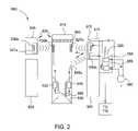
- FIG. 2is a diagram showing a torque sub.
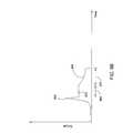
- FIG. 3Ais a partial cross section view of a connection between threaded premium grade tubulars.
- FIG. 3Bis a partial cross section view of a connection between threaded premium grade tubulars in which a seal condition is formed by engagement between sealing surfaces.
- FIG. 3Cis a partial cross section view of a connection between threaded premium grade tubulars in which a shoulder condition is formed by engagement between shoulder surfaces.
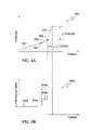
- FIG. 4Aillustrate a plot of torque with respect to turns for the premium connection.
- FIG. 4Billustrates plots of the rate of change in torque with respect to turns for the premium connection.
- FIG. 5illustrates post make-up release of elastic energy of the premium tubular and/or top drive.
- FIGS. 6A and 6Billustrate overshooting a premium connection due to kinetic energy of the top drive and/or premium tubular.
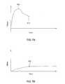
- FIGS. 7A and 7Billustrate inertial torque of a premium tubular and/or top drive.
- FIG. 8is a block diagram illustrating a tubular make-up system, according to one embodiment of the present invention.
- FIG. 9Aillustrates a method for controllably releasing stored elastic energy of the premium tubular and/or the top drive, according to another embodiment of the present invention.
- FIG. 9Billustrates an alternative method for controllably releasing stored elastic energy of the premium tubular and/or the top drive.
- FIGS. 10A and 10Billustrate a method for preventing overshoot of the connection, according to another embodiment of the present invention.
- FIG. 1is a side view of a drilling rig 10 having a top drive 100 , an elevator 35 , and a spider 60 .
- An upper end of a stack of tubulars 70is shown on the rig 10 .
- the tubular 70may be placed in position below the top drive 100 by the elevator 35 in order for the top drive having a gripping device (e.g., a spear 145 or torque head (not shown)) to engage the tubular.
- a gripping devicee.g., a spear 145 or torque head (not shown)
- the rig 10may be built at the surface 45 of the wellbore 50 .
- the rig 10may include a traveling block 20 that is suspended by wires 25 from draw works 15 and holds the top drive 100 .
- the top drive 100includes the spear 145 or torque head for engaging the tubular 70 and a motor 140 to rotate the tubular 70 .
- the motor 140may be either electrically or hydraulically driven.
- the motor 140rotates and threads the tubular 70 into the tubular string 80 extending into the wellbore 50 .
- the motor 140can also rotate a drill string having a drill bit at an end, or for any other purposes requiring rotational movement of a tubular or a tubular string.
- the top drive 100is shown having a railing system 30 coupled thereto.
- the railing system 30prevents the top drive 100 from rotational movement during rotation of the tubular 70 , but allows for vertical movement of the top drive under the traveling block 110 .
- the top drive 100may lower and thread the tubular into the tubular string. Additionally, the spider 60 , disposed in a platform 40 of the drilling rig 100 , is shown engaged around the tubular string 80 that extends into wellbore 50 .
- the elevator 35 and the top drive 100may be connected to the traveling block 20 via a compensator.
- the compensatormay function similar to a spring to compensate for vertical movement of the top drive 100 during threading of the tubular 70 to the tubular string 80 .
- the top drivemay include a torque sub 600 (see FIG. 2 ) to measure torque and rotation of the tubular 70 as it is being threaded to tubular string 80 .
- the torque sub 600may transmit the torque and rotation data about the threaded joint to a makeup controller 700 .
- the controller 700may be preprogrammed with acceptable values for rotation and torque for a particular joint. The controller may compare the rotation and the torque data to the stored acceptable values.
- the spider 60 , torque head, and spearmay each include slips, a bowl, and a piston.
- the slipsmay be wedge-shaped arranged to slide along a sloped inner wall of the bowl.
- the slipsmay be raised or lowered by the piston. When the slips are in the lowered position, they may close around/against the inner/outer surface of the respective tubulars 70 , 80 .
- the weight of the tubulars 70 , 80 and the resulting friction between the tubulars 70 , 80 and the slipsmay force the slips downward and inward, thereby tightening the grip on the tubular string.
- the slipsWhen the slips are in the raised position, the slips are opened and the tubulars 70 , 80 are free to move longitudinally in relation to the slips.
- the tubular string 80may be retained in a closed spider 60 and is thereby prevented from moving in a downward direction.
- the top drive 100may then be moved to engage the tubular 70 from a stack with the aid of the elevator 35 .
- the tubular 70may be a single tubular or a stand (typically be made up of two or three tubulars threaded together).
- Engagement of the tubular 70 by the top drive 100includes grasping the tubular and engaging the inner or outer surface thereof using the torque head or spear.
- the top drive 100then moves the tubular 70 into position above the tubular string 80 .
- the top drive 100may then rotate the tubular 70 relative to the tubular string 80 , thereby making up a threaded connection between the tubulars 70 , 80 .
- the spider 60may then be opened and disengage the tubular string 80 .
- the top drive 100may then lower the tubular string 70 , 80 through the opened spider 60 .
- the spider 60may then be closed around the tubular string 80 .
- the top drive 100may then disengage the tubular string 80 and can proceed to add another tubular 70 to the tubular string 80 .
- the above-described actsmay be utilized in running drill string in a drilling operation, running casing or liner to reinforce and/or drill the wellbore, or for assembling work strings to place wellbore components in the wellbore.
- the stepsmay also be reversed in order to disassemble the tubular string.
- FIG. 2illustrates the torque sub 600 .
- the torque sub 600may be connected to a quill of the top drive 100 for measuring a torque applied by the top drive 100 .
- the torque submay include a housing 605 , a torque shaft 610 rotationally and longitudinally coupled to the quill of the top drive, an interface 615 , and a controller 620 .
- the housing 605may be a tubular member having a bore therethrough.
- the interface 615 and the controller 620may both be mounted on the housing 605 .
- the interface 615may be made from a polymer.
- the torque shaft 610may extend through the bore of the housing 605 .
- the torque shaft 610may include one or more longitudinal slots, a groove, a reduced diameter portion, a sleeve (not shown), and a polymer shield (not shown).
- the groovemay receive a secondary coil 630 b which is wrapped therein.
- Disposed on an outer surface of the reduced diameter portionmay be one or more strain gages 680 .
- Each strain gage 680may be made of a thin foil grid and bonded to the tapered portion of the torque shaft 610 by a polymer support, such as an epoxy glue.
- the foil strain gauges 680may be made from metal, such as platinum, tungsten/nickel, or chromium.
- Four strain gages 680may be arranged in a Wheatstone bridge configuration.
- the strain gages 680may be disposed on the reduced diameter portion at a sufficient distance from either taper so that stress/strain transition effects at the tapers are fully dissipated.
- Strain gages 680may be arranged to measure torque and longitudinal load on the torque shaft 610 .
- the slotsmay provide a path for wiring between the secondary coil 630 b and the strain gages 680 and also house an antenna 645 a.
- the shieldmay be disposed proximate to the outer surface of the reduced diameter portion.
- the shieldmay be applied as a coating or thick film over strain gages 680 .
- Disposed between the shield and the sleevemay be electronic components 635 , 640 .
- the electronic components 635 , 640may be encased in a polymer mold 630 .
- the shieldmay absorb any forces that the mold 630 may otherwise exert on the strain gages 680 due to the hardening of the mold.
- the shieldmay also protect the delicate strain gages 680 from any chemicals present at the wellsite that may otherwise be inadvertently splattered on the strain gages 680 .
- the sleevemay be disposed along the reduced diameter portion.
- a recessmay be formed in each of the tapers to seat the shield.
- the sleeveforms a substantially continuous outside diameter of the torque shaft 610 through the reduced diameter portion.
- the sleevealso has an injection port formed therethrough (not shown) for filling fluid mold material to encase the electronic components 635 , 640 .
- a power source 660may be provided in the form of a battery pack in the controller 620 , an on-site generator, utility lines, or other suitable power source.
- the power source 660may be electrically coupled to a sine wave generator 650 .
- the sine wave generator 650may output a sine wave signal having a frequency less than nine kHz to avoid electromagnetic interference.
- the sine wave generator 650may be in electrical communication with a primary coil 630 a of an electrical power coupling 630 .
- the electrical power coupling 630may be an inductive energy transfer device. Even though the coupling 630 transfers energy between the non-rotating interface 615 and the rotatable torque shaft 610 , the coupling 630 may be devoid of any mechanical contact between the interface 615 and the torque shaft 610 . In general, the coupling 630 may act similarly to a common transformer in that it employs electromagnetic induction to transfer electrical energy from one circuit, via its primary coil 630 a , to another, via its secondary coil 630 b , and does so without direct connection between circuits. The coupling 630 includes the secondary coil 630 b mounted on the rotatable torque shaft 610 . The primary 630 a and secondary 630 b coils may be structurally decoupled from each other.
- the primary coil 630 amay be encased in a polymer 627 a , such as epoxy.
- the secondary coil 630 bmay be wrapped around a coil housing 627 b disposed in the groove.
- the coil housing 627 bmay be made from a polymer and may be assembled from two halves to facilitate insertion around the groove.
- the secondary coil 630 bmay then molded in the coil housing 627 b with a polymer.
- the primary 630 a and secondary coils 630 bmay be made from an electrically conductive material, such as copper, copper alloy, aluminum, or aluminum alloy.
- the primary 630 a and/or secondary 630 b coilsmay be jacketed with an insulating polymer.
- the alternating current (AC) signal generated by sine wave generator 650is applied to the primary coil 630 a .
- the resulting magnetic fluxinduces an AC signal across the secondary coil 630 b .
- the induced voltagecauses a current to flow to rectifier and direct current (DC) voltage regulator (DCRR) 635 .
- a constant poweris transmitted to the DCRR 635 , even when the torque shaft 610 is rotated by the top drive 100 .
- the DCRR 635may convert the induced AC signal from the secondary coil 630 b into a suitable DC signal for use by the other electrical components of the torque shaft 610 .
- the DCRRoutputs a first signal to the strain gages 680 and a second signal to an amplifier and microprocessor controller (AMC) 640 .
- the first signalis split into sub-signals which flow across the strain gages 680 , are then amplified by the amplifier 640 , and are fed to the microprocessor controller 640 .
- the microprocessor controller 640converts the analog signals from the strain gages 680 into digital signals, multiplexes them into a data stream, and outputs the data stream to a modem associated with microprocessor controller 640 .
- the modemmodulates the data stream for transmission from antenna 645 a .
- the antenna 645 atransmits the encoded data stream to an antenna 645 b disposed in the interface 615 .
- the antenna 645 bsends the received data stream to a modem 655 , which demodulates the data signal and outputs it to the controller 620 .
- the torque sub 600may further include a turns counter 665 , 670 .
- the turns countermay include a turns gear 665 and a proximity sensor 670 .
- the turns gear 665may be rotationally coupled to the torque shaft 610 .
- the proximity sensor 670may be disposed in the interface 615 for sensing movement of the gear 665 .
- the sensor 670may send an output signal to the controller 620 .
- a friction wheel/encoder device or a gear and pinion arrangementmay be used to measure turns of the torque shaft 610 .
- the controller 620may process the data from the strain gages 680 and the proximity sensor 670 to calculate respective torque, longitudinal load, and turns values therefrom.
- the controller 620may de-code the data stream from the strain gages 680 , combine that data stream with the turns data, and re-format the data into a usable input (e.g., analog, field bus, or Ethernet) for a make-up system 700 .
- a usable inpute.g., analog, field bus, or Ethernet
- tubularsFor oil wells, it is conventional to form such lengths of tubing to standards prescribed by the American Petroleum Institute (API).
- APIAmerican Petroleum Institute
- Each length of tubinghas an internal threading at one end and an external threading at another end.
- the externally-threaded end of one length of tubingis adapted to engage in the internally-threaded end of another length of tubing.
- API type connections between lengths of such tubingrely on thread interference and the interposition of a thread compound to provide a seal.
- API type connectionsare not sufficiently secure or leakproof.
- the lengths of tubingeach have tapered surfaces which engage one another to form the metal-to-metal sealing area. Engagement of the tapered surfaces is referred to as the “shoulder” position/condition.
- FIG. 3Aillustrates one form of a premium grade tubing connection 400 .
- FIG. 3Ashows a tapered premium grade tubing assembly 400 having a first tubular 402 joined to a second tubular 404 through a tubing coupling or box 406 .
- the end of each tubular 402 , 404has a tapered externally-threaded surface 408 which co-operates with a correspondingly tapered internally-threaded surface 410 on the coupling 406 .
- Each tubular 402 , 404is provided with a torque shoulder 412 which co-operates with a corresponding torque shoulder 414 on the coupling 406 .
- annular sealing area 416which is engageable with a co-operating annular sealing area 418 defined between the tapered portions 410 , 414 of the coupling 406 .
- the sealing area 416may be located at other positions in the connection.
- the tubulars 402 , 404(also known as pins), are engaged with the box 406 and then threaded into the box by relative rotation therewith.
- the annular sealing areas 416 , 418contact one another, as shown in FIG. 3B .
- This initial contactis referred to as the “seal condition”.
- the co-operating tapered torque shoulders 412 , 414contact and bear against one another at a machine detectable stage referred to as a “shoulder condition” or “shoulder torque”, as shown in FIG. 3C .
- FIG. 4Ashows a typical x-y plot (curve 500 ) illustrating the acceptable behavior of premium grade tubulars, such as the tapered premium grade tubing assembly 400 shown in FIGS. 3A-C .
- FIG. 4Bshows a corresponding chart plotting the rate of change in torque (y-axis) with respect to turns (x-axis).
- y-axisthe rate of change in torque
- x-axisthe rate of change in torque
- corresponding curve portion 502 a of the differential curve 500 a of FIG. 4Bis flat at some positive value.
- point 504corresponds to the seal condition shown in FIG. 3B and is plotted as the first step 504 a of the differential curve 500 a .
- the torque ratethen again stabilizes resulting in the linear curve portion 506 and the plateau 506 a .
- the seal conditionmay be too slight to be detectable.
- a discernable/detectable change in the torque rateoccurs when the shoulder condition is achieved (corresponding to FIG. 3C ), as represented by point 508 and step 508 a.
- top drive 100grips the tubular 402 at an end distal from the box 406 and lengths of the tubular 402 may range from about 20 ft to about 90 ft (depending on whether the tubular 402 is a single tubular or a stand of pre-made up tubulars), torsional deflection of the tubular 402 may be significant.
- the deflection of the tubular 402is inherently added to the rotation value provided by the turns counter 665 , 670 . Deflection of the top drive and the torque head or spear may also be significant.
- deflection of the tubular 402 and/or the top drive 100(including the torque head/spear and/or torque shaft 610 ) will be referred to as system deflection.
- the errormay be most noticeable at and past the shoulder condition.
- the system deflectionmay cause a substantial reduction in the step 508 in curve 500 a . This reduction could cause the shoulder detector 748 to mistake the shoulder condition for a seal condition (if the seal condition went undetected) which could result in a damaged connection.
- the make-up system 700may then stop the make-up of the connection upon reaching a predetermined turns value. However, a substantial portion of this value may instead be system deflection, thereby resulting in a connection that is insufficiently made-up. A poorly made-up connection may at best leak and at worse separate upon service in the wellbore or in a riser system. Further, the shift at the shoulder condition could cause the make-up system 700 to reject the connection even though the connection is acceptable especially if the make-up system expects the shoulder condition to be reached in a predetermined turns range.
- FIG. 5illustrates post make-up release of elastic energy of the premium tubular 402 and/or top drive 100 .
- the systemmay deflect.
- elastic energymay be stored by the system so that when the connection is made up or completed 205 and the dump signal is issued to the top drive 100 , the energy is released causing the tubular 402 to rotate in a breakout or loosening direction of the tubular 402 (usually counterclockwise) and then oscillate 210 until the energy dissipates. Breakout torque 215 (negative) may consequently be applied to the connection 400 , potentially loosening the connection.
- FIGS. 6A and 6Billustrate overshooting the premium connection 400 due to kinetic energy of the system.
- the make-up targetcalculated by any of various ways discussed herein, is illustrated at 305 .
- kinetic energy or momentum of the systemmay cause further rotation or overshoot after the dump signal is issued until make-up of the connection actually terminates at 310 .
- the overshootmay cause substantial additional torque to be exerted on the connection 400 , thereby damaging the connection.
- the overshootmay be minimized by reducing angular speed of the top drive 100 at the target 305 .
- FIGS. 7A and 7Billustrate inertial torque of a premium tubular and/or top drive.
- the figuresillustrate angular acceleration of the top drive 100 connected to the tubular string 80 while rotating the tubular string 80 (instead of making up a connection between tubular 70 and string 80 ).
- the systemstarts from rest and is rotationally accelerated an angular velocity at point 805 at which the angular velocity of the system is maintained at a first speed.
- the torqueincreases to a maximum of 810 and then decreases to a steady state value representative of dynamic friction of the system.
- the difference between maximum 810 and the steady state value 815represents the inertial torque required to accelerate the system.
- inertial torque due to system accelerationmay cause the torque sub to measure more torque than is actually applied to the connection 400 and inertial torque due to system deceleration may cause the torque sub to measure less torque than is actually applied to the connection.
- inertial torquemay skew the torque-turn curve and the differential torque/turn-turn curve, thereby potentially causing the connection 400 to be improperly made up.
- FIG. 8is a block diagram illustrating a tubular make-up system implementing the torque sub 600 of FIG. 2 .
- the tubular make-up system 700may include the top drive 100 , a top drive controller 765 , torque sub 600 , and the computer system 706 .
- the computer system 706may communicate with the top drive controller 765 via interface 760 .
- the interface 760may be analog or digital.
- the computer system 706may also serve as the top drive controller.
- a computer 716 of the computer system 706may monitor the turns count signals and torque signals from torque sub 600 and compare the measured values of these signals with predetermined values.
- the predetermined valuesmay be input by an operator for a particular tubing connection.
- the predetermined valuesmay be input to the computer 716 via an input device 718 , such as a keypad.
- Illustrative predetermined values which may be input, by an operator or otherwiseinclude a delta torque value 724 , a delta turns value 726 , minimum and maximum turns values 728 and minimum and maximum torque values 730 .
- various outputmay be observed by an operator on output device, such as a display screen, which may be one of a plurality of output devices 720 .
- an operatormay observe the various predefined values which have been input for a particular tubing connection. Further, the operator may observe graphical information such as a representation of the torque rate curve 500 and the torque rate differential curve 500 a .
- the plurality of output devices 720may also include a printer such as a strip chart recorder or a digital printer, or a plotter, such as an x-y plotter, to provide a hard copy output.
- the plurality of output devices 720may further include a horn or other audio equipment to alert the operator of significant events occurring during make-up, such as the shoulder condition, the terminal connection position and/or a bad connection.
- the computer system 706may output a dump signal to the top drive controller 765 to automatically shut down or reduce the torque exerted by the top drive 100 .
- dump signal 722may be issued upon detecting the terminal connection position and/or a bad connection.
- the comparison of measured turn count values and torque values with respect to predetermined valuesis performed by one or more functional units of the computer 716 .
- the functional unitsmay generally be implemented as hardware, software or a combination thereof.
- the functional unitsmay include a torque-turns plotter algorithm 732 , a process monitor 734 , a torque rate differential calculator 736 , a smoothing algorithm 738 , a sampler 740 , a comparator 742 , and a compensator 752 .
- the process monitor 734may include a thread engagement detection algorithm 744 , a seal detection algorithm 746 and a shoulder detection algorithm 748 .
- the functional unitsmay be performed by a single unit.
- the functional units 732 - 742 , 752 , 765may be considered logical representations, rather than well-defined and individually distinguishable components of software or hardware.
- the compensator 752may include a database of predefined values or a formula derived therefrom for various torque and system deflections resulting from application of various torque on the top drive unit 100 . These values (or formula) may be calculated theoretically or measured empirically. Since the top drive unit 100 is a relatively complex machine, it may be preferable to measure deflections at various torque since a theoretical calculation may require extensive computer modeling, e.g. finite element analysis. Empirical measurement may be accomplished by substituting a rigid member, e.g. a blank tubular, for the premium grade assembly 400 and causing the top drive 100 to exert a range of torques corresponding to a range that would be exerted on the tubular grade assembly to properly make-up a connection.
- a rigid membere.g. a blank tubular
- the blankmay be only a few feet long so as not to compromise rigidity.
- the torque and rotation values provided by torque sub 600would then be monitored and recorded in a database.
- the testmay then be repeated to provide statistical samples. Statistical analysis may then be performed to exclude anomalies and/or derive a formula.
- the testmay also be repeated for different size tubulars to account for any change in the stiffness of the top drive 100 due to adjustment of the units for different size tubulars. Alternatively, only deflections for higher values (e.g. at a range from the shoulder condition to the terminal condition) need be measured.
- Deflection of tubular member 402may also be added into the system deflection. Theoretical formulas for this deflection may readily be available.
- the end of member 402 distal from the top drivemay simply be locked into a spider.
- the top drive 100may then be operated across the desired torque range while measuring and recording the torque and rotation values from the torque sub 600 .
- the measured rotation valuewill then be the rotational deflection of both the top drive 100 and the tubular member 402 .
- the deflection compensatormay only include a formula or database of torques and deflections for just the tubular member 402 .
- the compensator 752may also include a moment of inertia for the tubular 402 (and may include moments of inertia for the rest of the system). These values (or formula) may be calculated theoretically or measured empirically. Since the top drive 100 is a relatively complex machine, it may be preferable to measure moments of inertia at a constant angular acceleration since a theoretical calculation may require extensive computer modeling, e.g., finite element analysis. Empirical measurement for the system may be accomplished just after the tubular 402 is engaged with the tubular 404 while the connection 400 is still loose. The top drive may be accelerated at a constant angular acceleration and the torque measured with the torque sub.
- the top drive 100may then be decelerated at a constant angular deceleration and the torque again measured.
- the torquemay be divided by the angular acceleration to determine the moment of inertia.
- the angular accelerationmay be monitored during make up of the connection 400 to compensate the measured torque value for system inertia. Since the empirical test is relatively simple, it may be repeated for each tubular 402 .
- a database of inertial torque at different angular accelerationsmay be instead used to compensate the torque value.
- the top drive controllermay be programmed to compensate for system inertia.
- the box 406is usually made-up on tubular 404 off-site before the tubulars 402 , 404 are transported to the rig. Alternatively, the box 406 may be welded to the tubular 404 .
- One of the threaded memberse.g., tubular 402
- the top drive 100while the other tubular 404 is held by the spider 60 .
- the applied torque and rotationare measured at regular intervals throughout a pipe connection makeup.
- the box 406may be secured against rotation so that the turns count signals accurately reflect the rotation of the tubular 402 .
- a second turns countermay be provided to sense the rotation of the box 406 . The turns count signal issued by the second turns counter may then be used to correct (for any rotation of the box 406 ) the turns count signals.
- the rotation valuemay be compensated for system deflection and/or inertial torque.
- the compensator 752may utilize the measured torque value to reference the predefined values (or formula) to find/calculate the system deflection for the measured torque value. The compensator 752 may then subtract the system deflection value from the measured rotation value to calculate a corrected rotation value.
- a theoretical formula for deflection of the tubular member 402may be pre-programmed into the deflection compensator 752 for a separate calculation of deflection and then the deflection may be added to the top drive deflection to calculate the system deflection during each interval.
- the compensator 752may only compensate for the deflection of the tubular member 402 .
- the compensator 752may compensate the measured torque value for inertial torque using the theoretical/empirical system moment of inertia and measured/calculated angular acceleration.
- the frequency with which torque and rotation are measuredmay be specified by the sampler 740 .
- the sampler 740may be configurable, so that an operator may input a desired sampling frequency.
- the corrected torque and corrected rotation valuesmay be stored as a paired set in a buffer area of computer memory.
- the rate of change of corrected torque with respect to corrected rotation(e.g., a derivative) is calculated for each paired set of measurements by the torque rate differential calculator 736 . At least two measurements are needed before a rate of change calculation can be made.
- the smoothing algorithm 738operates to smooth the derivative curve (e.g., by way of a running average). These three values (corrected torque, corrected rotation and rate of change of torque with respect to rotation) may then be plotted by the plotter 732 for display on the output device 720 .
- the predetermined valuesmay be minimum and maximum torque values and minimum and maximum turn values.
- the process monitor 734determines the occurrence of various events and whether to continue rotation or abort the makeup.
- the thread engagement detection algorithm 744monitors for thread engagement of the two threaded members. Upon detection of thread engagement a first marker is stored. The marker may be quantified, for example, by time, rotation, torque, a derivative of torque or time, or a combination of any such quantifications.
- the seal detection algorithm 746monitors for the seal condition. This may be accomplished by comparing the calculated derivative (rate of change of torque) with a predetermined threshold seal condition value. A second marker indicating the seal condition is stored when the seal condition is detected. At this point, the turns value and torque value at the seal condition may be evaluated by the connection evaluator 750 .
- a determinationmay be made as to whether the corrected turns value and/or torque value are within specified limits.
- the specified limitsmay be predetermined, or based off of a value measured during makeup. If the connection evaluator 750 determines a bad connection, rotation may be terminated. Otherwise rotation continues and the shoulder detection algorithm 748 monitors for shoulder condition. This may be accomplished by comparing the calculated derivative (rate of change of torque) with a predetermined threshold shoulder condition value. When the shoulder condition is detected, a third marker indicating the shoulder condition is stored. The connection evaluator 750 may then determine whether the turns value and torque value at the shoulder condition are acceptable.
- connection evaluator 750determines whether the change in torque and rotation between these second and third markers are within a predetermined acceptable range. If the values, or the change in values, are not acceptable, the connection evaluator 750 indicates a bad connection. If, however, the values/change are/is acceptable, the target calculator calculates a target torque value and/or target turns value.
- the target valuemay be calculated by adding a predetermined delta value (torque or turns) to a measured/corrected reference value(s).
- the measured/corrected reference valuemay be the torque value or turns value corresponding to the detected shoulder condition.
- a target torque value and a target turns valueare calculated based off of the measured/corrected torque value and turns value, respectively, corresponding to the detected shoulder condition.
- the target detector 754monitors for the calculated target value(s). Once the target value is reached, rotation is terminated. In the event both a target torque value and a target turns value are used for a given makeup, rotation may continue upon reaching the first target or until reaching the second target, so long as both values (torque and turns) stay within an acceptable range. Alternatively, the compensator 752 may not be activated until after the shoulder condition has been detected. Alternatively or additionally, the connection evaluator may compare the rate of change in torque with respect to rotation after the shoulder condition (see 510 ) to a predetermined value to determine acceptability of the connection.
- FIGS. 10A and 10Billustrate a method for preventing overshoot of the connection, according to another embodiment of the present invention.
- the angular speed of the top drivemay begin to be slowed 1015 prior to reaching the target value 1005 . Decreasing of the top drive speed may begin 1015 once the connection is substantially complete, such as at fifty percent of the recommended or maximum torque or turns value, at the seal condition, at the shoulder condition, or therebetween.
- the top drive speedmay be gradually reduced to a target speed 1010 which may be substantially (e.g., a reduction by fifty percent or more) less than the speed 1015 at which the top drive would have been at the target (see also 315 ).
- the system kinetic energy or momentummay be negligible at the reduced speed so that the dump signal may be issued contemporaneously with detection of the target value or a slightly before (using a predicted target value time/turns).
- the top drivemay include a clutch (not shown). Instead of issuing a dump signal to the top drive, the clutch may be operated to disengage the top drive from the tubular 402 when the target is reached, thereby preventing overshoot. The disengagement may be instantaneous or gradual proximate to the target.
- FIG. 9Aillustrates a method for controllably releasing stored elastic energy of the system, according to another embodiment of the present invention.
- a controlled approachmay be made.
- the output torque of the top drivemay be gradually decreased 915 over a predetermined interval of time 910 control unwinding of the tubular 402 due to release of the stored elastic energy in the system.
- break-out torque exerted on the connection 400may be prevented entirely or at least maintained below a predetermined acceptable level (e.g., one-half of the final make-up torque 905 ).
- FIG. 9Billustrates an alternative method for controllably releasing stored elastic energy of the system.
- the output torque of the top drive 100may be substantially reduced from the final make-up torque 950 to a second torque 955 and maintained for a predetermined interval of time 960 and then gradually reduced 965 over a second predetermined period of time 970 to control unwinding of the tubular 402 due to release of the stored elastic energy in the system.
- the second torque 955may be substantially less, e.g. one-half, of the final makeup torque 950 .
- the torquemay be reduced in two or more steps, such as reduction to a second torque which may be two-thirds the final make up torque 950 for a predetermined period of time and then reduced to a third torque which may be one-third of the final make-up torque instead of the gradual release 965 .
- a braking systemmay be added to the top drive.
- the braking systemmay be a disc-brake system or a drum brake system.
- a hydraulic or pneumatic damper systemmay be used to dissipate the elastic energy stored in the system.
- the braking or damper systemsmay be especially useful for the clutch alternative, discussed above.
Landscapes
- Engineering & Computer Science (AREA)
- Life Sciences & Earth Sciences (AREA)
- Geology (AREA)
- Mining & Mineral Resources (AREA)
- Mechanical Engineering (AREA)
- Physics & Mathematics (AREA)
- Environmental & Geological Engineering (AREA)
- Fluid Mechanics (AREA)
- General Life Sciences & Earth Sciences (AREA)
- Geochemistry & Mineralogy (AREA)
- Earth Drilling (AREA)
- Non-Disconnectible Joints And Screw-Threaded Joints (AREA)
Abstract
Description
Claims (39)
Priority Applications (1)
| Application Number | Priority Date | Filing Date | Title |
|---|---|---|---|
| US12/429,706US8297347B2 (en) | 2008-04-25 | 2009-04-24 | Method of controlling torque applied to a tubular connection |
Applications Claiming Priority (2)
| Application Number | Priority Date | Filing Date | Title |
|---|---|---|---|
| US4807108P | 2008-04-25 | 2008-04-25 | |
| US12/429,706US8297347B2 (en) | 2008-04-25 | 2009-04-24 | Method of controlling torque applied to a tubular connection |
Publications (2)
| Publication Number | Publication Date |
|---|---|
| US20090266539A1 US20090266539A1 (en) | 2009-10-29 |
| US8297347B2true US8297347B2 (en) | 2012-10-30 |
Family
ID=41213846
Family Applications (1)
| Application Number | Title | Priority Date | Filing Date |
|---|---|---|---|
| US12/429,706Active2030-05-31US8297347B2 (en) | 2008-04-25 | 2009-04-24 | Method of controlling torque applied to a tubular connection |
Country Status (6)
| Country | Link |
|---|---|
| US (1) | US8297347B2 (en) |
| EP (1) | EP2288783B1 (en) |
| AU (1) | AU2009240457B2 (en) |
| CA (1) | CA2722096C (en) |
| DK (1) | DK2288783T3 (en) |
| WO (1) | WO2009132264A2 (en) |
Cited By (8)
| Publication number | Priority date | Publication date | Assignee | Title |
|---|---|---|---|---|
| US9238950B2 (en) | 2014-01-10 | 2016-01-19 | National Oilwell Varco, L.P. | Blowout preventer with packer assembly and method of using same |
| US9410383B2 (en) | 2013-09-12 | 2016-08-09 | National Oilwell Varco, L.P. | Method and apparatus for connecting tubulars of a wellsite |
| US9506304B2 (en) | 2013-09-12 | 2016-11-29 | National Oilwell Varco, L.P. | Apparatus and method for connecting tubulars of a wellsite |
| US9732573B2 (en) | 2014-01-03 | 2017-08-15 | National Oilwell DHT, L.P. | Downhole activation assembly with offset bore and method of using same |
| US11359445B2 (en)* | 2017-02-03 | 2022-06-14 | Weatherford Technology Holdings, Llc | Apparatus and method of connecting tubulars |
| WO2024116001A1 (en) | 2022-11-30 | 2024-06-06 | Weatherford Technology Holdings, Llc | Agent file reference:casing connection make-up with top drive and casing running tool |
| US12134942B2 (en) | 2023-03-10 | 2024-11-05 | Baker Hughes Oilfield Operations Llc | Control of tubular connections based on estimation of turns remaining |
| US12331600B2 (en) | 2022-08-31 | 2025-06-17 | Weatherford Technology Holdings, Llc | Safety clutch system for circulation/fill-up/flowback tool |
Families Citing this family (12)
| Publication number | Priority date | Publication date | Assignee | Title |
|---|---|---|---|---|
| EP2288783B1 (en)* | 2008-04-25 | 2016-02-17 | Weatherford Technology Holdings, LLC | Method of controlling torque applied to a tubular connection |
| US8534354B2 (en)* | 2010-03-05 | 2013-09-17 | Schlumberger Technology Corporation | Completion string deployment in a subterranean well |
| US8651175B2 (en)* | 2011-01-14 | 2014-02-18 | Tesco Corporation | Top drive output torque measurement method |
| US8726743B2 (en) | 2011-06-22 | 2014-05-20 | Weatherford/Lamb, Inc. | Shoulder yielding detection during tubular makeup |
| US10697260B2 (en)* | 2017-02-02 | 2020-06-30 | Cameron International Corporation | Tubular rotation detection system and method |
| US10465458B2 (en)* | 2017-02-03 | 2019-11-05 | Weatherford Technology Holdings, Llc | Apparatus and method of connecting tubulars |
| US10422450B2 (en)* | 2017-02-03 | 2019-09-24 | Weatherford Technology Holdings, Llc | Autonomous connection evaluation and automated shoulder detection for tubular makeup |
| US10802899B2 (en) | 2017-07-03 | 2020-10-13 | Transocean Sedco Forex Ventures Limited | Drilling tubular identification |
| US10844675B2 (en)* | 2018-12-21 | 2020-11-24 | Weatherford Technology Holdings, Llc | Autonomous connection makeup and evaluation |
| US11592346B2 (en) | 2020-02-26 | 2023-02-28 | Weatherford Technology Holdings, Llc | Multi-range load cell |
| WO2021188432A1 (en)* | 2020-03-18 | 2021-09-23 | Schlumberger Technology Corporation | Automatically detecting and unwinding accumulated drill string torque |
| US11136838B1 (en) | 2020-04-22 | 2021-10-05 | Weatherford Technology Holdings, Llc | Load cell for a tong assembly |
Citations (46)
| Publication number | Priority date | Publication date | Assignee | Title |
|---|---|---|---|---|
| US3368396A (en)* | 1964-09-14 | 1968-02-13 | Exxon Production Research Co | Assembling pipe strings with leak-tight joints |
| US3594587A (en)* | 1968-12-24 | 1971-07-20 | Barmag Barmer Maschf | Device for transmitting signals between a rotatable member and a fixed member |
| US3745820A (en)* | 1969-04-04 | 1973-07-17 | Exxon Production Research Co | Leak proof threaded connections |
| US3855857A (en)* | 1973-05-09 | 1974-12-24 | Schlumberger Technology Corp | Force-measuring apparatus for use in a well bore pipe string |
| US4008773A (en)* | 1975-05-19 | 1977-02-22 | Standard Pressed Steel Co. | Tightening system |
| US4091451A (en)* | 1977-04-26 | 1978-05-23 | Weatherford/Lamb, Inc. | Method of and apparatus for making up a threaded connection |
| US4106176A (en)* | 1977-04-06 | 1978-08-15 | Ingersoll-Rand Company | Method and apparatus for fastener tensioning |
| US4176436A (en)* | 1978-09-12 | 1979-12-04 | Baker International Corporation | Method and apparatus for counting turns when making threaded joints |
| GB2099620A (en) | 1981-04-10 | 1982-12-08 | Baker Int Corp | Apparatus for counting turns when making threaded joints including an increased resolution turns counter |
| US4365402A (en)* | 1978-09-12 | 1982-12-28 | Baker International Corporation | Method for counting turns when making threaded joints |
| US4402052A (en)* | 1981-04-10 | 1983-08-30 | Baker International Corporation | Apparatus for making threaded joints incorporating a make-up speed controller |
| US4404559A (en)* | 1981-05-26 | 1983-09-13 | Battelle Memorial Institute | Rotative power and signal coupling |
| GB2115940A (en) | 1982-02-24 | 1983-09-14 | Vallourec | Ensuring correct assembly of screwed pipe joints |
| US4592125A (en)* | 1983-10-06 | 1986-06-03 | Salvesen Drilling Limited | Method and apparatus for analysis of torque applied to a joint |
| US4709182A (en)* | 1985-06-20 | 1987-11-24 | Veb Chemieanlagenbaukombinat Leipzig/Grimma | Method and apparatus for tightening or loosening screw-type connections |
| US4715451A (en)* | 1986-09-17 | 1987-12-29 | Atlantic Richfield Company | Measuring drillstem loading and behavior |
| US4867236A (en)* | 1987-10-09 | 1989-09-19 | W-N Apache Corporation | Compact casing tongs for use on top head drive earth drilling machine |
| US4875530A (en)* | 1987-09-24 | 1989-10-24 | Parker Technology, Inc. | Automatic drilling system |
| US5205163A (en)* | 1990-07-10 | 1993-04-27 | Schlumberger Technology Corporation | Method and apparatus for determining the torque applied to a drillstring at the surface |
| US5245265A (en) | 1989-01-28 | 1993-09-14 | Frank's International Ltd. | System to control a motor for the assembly or dis-assembly of two members |
| US5245877A (en)* | 1991-03-12 | 1993-09-21 | Weatherford U.S., Inc. | Tong load cell assembly |
| US5272925A (en)* | 1990-10-19 | 1993-12-28 | Societe Natinoale Elf Aquitaine (Production) | Motorized rotary swivel equipped with a dynamometric measuring unit |
| US5402688A (en)* | 1993-03-17 | 1995-04-04 | Sumitomo Metal Industries, Ltd. | Method and apparatus for determining the tightened condition of a pipe joint |
| US5637968A (en)* | 1993-10-25 | 1997-06-10 | The Stanley Works | Power tool with automatic downshift feature |
| US5689871A (en)* | 1982-05-19 | 1997-11-25 | Carstensen; Kenneth J. | Couplings for standard A.P.I. tubings and casings and methods of assembling the same |
| US6241032B1 (en)* | 1999-09-07 | 2001-06-05 | Thomas E. Falgout, Sr. | One-way drill string clutch |
| US6374706B1 (en)* | 2001-01-25 | 2002-04-23 | Frederic M. Newman | Sucker rod tool |
| US6516896B1 (en)* | 2001-07-30 | 2003-02-11 | The Stanley Works | Torque-applying tool and control therefor |
| US6536520B1 (en)* | 2000-04-17 | 2003-03-25 | Weatherford/Lamb, Inc. | Top drive casing system |
| WO2003069113A2 (en) | 2002-02-12 | 2003-08-21 | Weatherford/Lamb, Inc. | Wrenching tong |
| US20030178847A1 (en)* | 2002-03-19 | 2003-09-25 | Galle Edward M. | Threaded connection makeup method |
| US6662110B1 (en)* | 2003-01-14 | 2003-12-09 | Schlumberger Technology Corporation | Drilling rig closed loop controls |
| US20040144547A1 (en)* | 2000-04-17 | 2004-07-29 | Thomas Koithan | Methods and apparatus for applying torque and rotation to connections |
| US20050077084A1 (en) | 2003-10-09 | 2005-04-14 | John Kracik | Make-up control system for tubulars |
| US7028585B2 (en)* | 1999-11-26 | 2006-04-18 | Weatherford/Lamb, Inc. | Wrenching tong |
| US7044238B2 (en)* | 2002-04-19 | 2006-05-16 | Hutchinson Mark W | Method for improving drilling depth measurements |
| US7073598B2 (en)* | 2001-05-17 | 2006-07-11 | Weatherford/Lamb, Inc. | Apparatus and methods for tubular makeup interlock |
| US20070107912A1 (en) | 2001-05-17 | 2007-05-17 | Doyle Boutwell | System and method for deflection compensation in power drive system for connection of tubulars |
| US7286623B2 (en)* | 1998-11-25 | 2007-10-23 | Texas Instruments Incorporated | Plural circuit selection using role reversing control inputs |
| US20070251701A1 (en)* | 2006-04-27 | 2007-11-01 | Michael Jahn | Torque sub for use with top drive |
| US20090151934A1 (en)* | 2007-12-12 | 2009-06-18 | Karsten Heidecke | Top drive system |
| US7588099B2 (en)* | 2006-01-27 | 2009-09-15 | Varco I/P, Inc. | Horizontal drilling system with oscillation control |
| US7594540B2 (en)* | 2002-11-27 | 2009-09-29 | Weatherford/Lamb, Inc. | Methods and apparatus for applying torque and rotation to connections |
| US20090266539A1 (en)* | 2008-04-25 | 2009-10-29 | Graham Ruark | Method of controlling torque applied to a tubular connection |
| US20090274545A1 (en)* | 2008-05-02 | 2009-11-05 | Martin Liess | Tubular Handling Apparatus |
| US7882902B2 (en)* | 2006-11-17 | 2011-02-08 | Weatherford/Lamb, Inc. | Top drive interlock |
- 2009
- 2009-04-24EPEP09735636.4Apatent/EP2288783B1/enactiveActive
- 2009-04-24USUS12/429,706patent/US8297347B2/enactiveActive
- 2009-04-24WOPCT/US2009/041651patent/WO2009132264A2/enactiveApplication Filing
- 2009-04-24AUAU2009240457Apatent/AU2009240457B2/enactiveActive
- 2009-04-24CACA2722096Apatent/CA2722096C/enactiveActive
- 2009-04-24DKDK09735636.4Tpatent/DK2288783T3/enactive
Patent Citations (55)
| Publication number | Priority date | Publication date | Assignee | Title |
|---|---|---|---|---|
| US3368396A (en)* | 1964-09-14 | 1968-02-13 | Exxon Production Research Co | Assembling pipe strings with leak-tight joints |
| US3594587A (en)* | 1968-12-24 | 1971-07-20 | Barmag Barmer Maschf | Device for transmitting signals between a rotatable member and a fixed member |
| US3745820A (en)* | 1969-04-04 | 1973-07-17 | Exxon Production Research Co | Leak proof threaded connections |
| US3855857A (en)* | 1973-05-09 | 1974-12-24 | Schlumberger Technology Corp | Force-measuring apparatus for use in a well bore pipe string |
| US4008773A (en)* | 1975-05-19 | 1977-02-22 | Standard Pressed Steel Co. | Tightening system |
| US4106176A (en)* | 1977-04-06 | 1978-08-15 | Ingersoll-Rand Company | Method and apparatus for fastener tensioning |
| US4091451A (en)* | 1977-04-26 | 1978-05-23 | Weatherford/Lamb, Inc. | Method of and apparatus for making up a threaded connection |
| US4176436A (en)* | 1978-09-12 | 1979-12-04 | Baker International Corporation | Method and apparatus for counting turns when making threaded joints |
| US4365402A (en)* | 1978-09-12 | 1982-12-28 | Baker International Corporation | Method for counting turns when making threaded joints |
| GB2099620A (en) | 1981-04-10 | 1982-12-08 | Baker Int Corp | Apparatus for counting turns when making threaded joints including an increased resolution turns counter |
| US4402052A (en)* | 1981-04-10 | 1983-08-30 | Baker International Corporation | Apparatus for making threaded joints incorporating a make-up speed controller |
| US4404559A (en)* | 1981-05-26 | 1983-09-13 | Battelle Memorial Institute | Rotative power and signal coupling |
| GB2115940A (en) | 1982-02-24 | 1983-09-14 | Vallourec | Ensuring correct assembly of screwed pipe joints |
| US5689871A (en)* | 1982-05-19 | 1997-11-25 | Carstensen; Kenneth J. | Couplings for standard A.P.I. tubings and casings and methods of assembling the same |
| US4592125A (en)* | 1983-10-06 | 1986-06-03 | Salvesen Drilling Limited | Method and apparatus for analysis of torque applied to a joint |
| US4709182A (en)* | 1985-06-20 | 1987-11-24 | Veb Chemieanlagenbaukombinat Leipzig/Grimma | Method and apparatus for tightening or loosening screw-type connections |
| US4715451A (en)* | 1986-09-17 | 1987-12-29 | Atlantic Richfield Company | Measuring drillstem loading and behavior |
| US4875530A (en)* | 1987-09-24 | 1989-10-24 | Parker Technology, Inc. | Automatic drilling system |
| US4867236A (en)* | 1987-10-09 | 1989-09-19 | W-N Apache Corporation | Compact casing tongs for use on top head drive earth drilling machine |
| US5245265A (en) | 1989-01-28 | 1993-09-14 | Frank's International Ltd. | System to control a motor for the assembly or dis-assembly of two members |
| US5205163A (en)* | 1990-07-10 | 1993-04-27 | Schlumberger Technology Corporation | Method and apparatus for determining the torque applied to a drillstring at the surface |
| US5272925A (en)* | 1990-10-19 | 1993-12-28 | Societe Natinoale Elf Aquitaine (Production) | Motorized rotary swivel equipped with a dynamometric measuring unit |
| US5245877A (en)* | 1991-03-12 | 1993-09-21 | Weatherford U.S., Inc. | Tong load cell assembly |
| US5402688A (en)* | 1993-03-17 | 1995-04-04 | Sumitomo Metal Industries, Ltd. | Method and apparatus for determining the tightened condition of a pipe joint |
| US5637968A (en)* | 1993-10-25 | 1997-06-10 | The Stanley Works | Power tool with automatic downshift feature |
| US7286623B2 (en)* | 1998-11-25 | 2007-10-23 | Texas Instruments Incorporated | Plural circuit selection using role reversing control inputs |
| US6241032B1 (en)* | 1999-09-07 | 2001-06-05 | Thomas E. Falgout, Sr. | One-way drill string clutch |
| US7028585B2 (en)* | 1999-11-26 | 2006-04-18 | Weatherford/Lamb, Inc. | Wrenching tong |
| US6814149B2 (en)* | 1999-11-26 | 2004-11-09 | Weatherford/Lamb, Inc. | Apparatus and method for positioning a tubular relative to a tong |
| US20040144547A1 (en)* | 2000-04-17 | 2004-07-29 | Thomas Koithan | Methods and apparatus for applying torque and rotation to connections |
| US7296623B2 (en)* | 2000-04-17 | 2007-11-20 | Weatherford/Lamb, Inc. | Methods and apparatus for applying torque and rotation to connections |
| US6536520B1 (en)* | 2000-04-17 | 2003-03-25 | Weatherford/Lamb, Inc. | Top drive casing system |
| US20030164276A1 (en)* | 2000-04-17 | 2003-09-04 | Weatherford/Lamb, Inc. | Top drive casing system |
| US6374706B1 (en)* | 2001-01-25 | 2002-04-23 | Frederic M. Newman | Sucker rod tool |
| US7568522B2 (en)* | 2001-05-17 | 2009-08-04 | Weatherford/Lamb, Inc. | System and method for deflection compensation in power drive system for connection of tubulars |
| US7073598B2 (en)* | 2001-05-17 | 2006-07-11 | Weatherford/Lamb, Inc. | Apparatus and methods for tubular makeup interlock |
| US20070107912A1 (en) | 2001-05-17 | 2007-05-17 | Doyle Boutwell | System and method for deflection compensation in power drive system for connection of tubulars |
| US6516896B1 (en)* | 2001-07-30 | 2003-02-11 | The Stanley Works | Torque-applying tool and control therefor |
| WO2003069113A2 (en) | 2002-02-12 | 2003-08-21 | Weatherford/Lamb, Inc. | Wrenching tong |
| US20030178847A1 (en)* | 2002-03-19 | 2003-09-25 | Galle Edward M. | Threaded connection makeup method |
| US7044238B2 (en)* | 2002-04-19 | 2006-05-16 | Hutchinson Mark W | Method for improving drilling depth measurements |
| US7318488B2 (en)* | 2002-04-19 | 2008-01-15 | Hutchinson Mark W | Method for classifying data measured during drilling operations |
| US7306054B2 (en)* | 2002-04-19 | 2007-12-11 | Hutchinson Mark W | Method for improving drilling depth measurements |
| US7594540B2 (en)* | 2002-11-27 | 2009-09-29 | Weatherford/Lamb, Inc. | Methods and apparatus for applying torque and rotation to connections |
| US6662110B1 (en)* | 2003-01-14 | 2003-12-09 | Schlumberger Technology Corporation | Drilling rig closed loop controls |
| US7100698B2 (en)* | 2003-10-09 | 2006-09-05 | Varco I/P, Inc. | Make-up control system for tubulars |
| US20050077084A1 (en) | 2003-10-09 | 2005-04-14 | John Kracik | Make-up control system for tubulars |
| US7588099B2 (en)* | 2006-01-27 | 2009-09-15 | Varco I/P, Inc. | Horizontal drilling system with oscillation control |
| US20070251701A1 (en)* | 2006-04-27 | 2007-11-01 | Michael Jahn | Torque sub for use with top drive |
| US7757759B2 (en)* | 2006-04-27 | 2010-07-20 | Weatherford/Lamb, Inc. | Torque sub for use with top drive |
| US20100243273A1 (en)* | 2006-04-27 | 2010-09-30 | Michael Jahn | Torque sub for use with top drive |
| US7882902B2 (en)* | 2006-11-17 | 2011-02-08 | Weatherford/Lamb, Inc. | Top drive interlock |
| US20090151934A1 (en)* | 2007-12-12 | 2009-06-18 | Karsten Heidecke | Top drive system |
| US20090266539A1 (en)* | 2008-04-25 | 2009-10-29 | Graham Ruark | Method of controlling torque applied to a tubular connection |
| US20090274545A1 (en)* | 2008-05-02 | 2009-11-05 | Martin Liess | Tubular Handling Apparatus |
Non-Patent Citations (2)
| Title |
|---|
| Canadian Office Action for Application No. 2,722,096 dated Feb. 28, 2012. |
| PCT Written Opinion and Search Report for International Application No. PCT/US2009/041651 dated Feb. 22, 2011. |
Cited By (8)
| Publication number | Priority date | Publication date | Assignee | Title |
|---|---|---|---|---|
| US9410383B2 (en) | 2013-09-12 | 2016-08-09 | National Oilwell Varco, L.P. | Method and apparatus for connecting tubulars of a wellsite |
| US9506304B2 (en) | 2013-09-12 | 2016-11-29 | National Oilwell Varco, L.P. | Apparatus and method for connecting tubulars of a wellsite |
| US9732573B2 (en) | 2014-01-03 | 2017-08-15 | National Oilwell DHT, L.P. | Downhole activation assembly with offset bore and method of using same |
| US9238950B2 (en) | 2014-01-10 | 2016-01-19 | National Oilwell Varco, L.P. | Blowout preventer with packer assembly and method of using same |
| US11359445B2 (en)* | 2017-02-03 | 2022-06-14 | Weatherford Technology Holdings, Llc | Apparatus and method of connecting tubulars |
| US12331600B2 (en) | 2022-08-31 | 2025-06-17 | Weatherford Technology Holdings, Llc | Safety clutch system for circulation/fill-up/flowback tool |
| WO2024116001A1 (en) | 2022-11-30 | 2024-06-06 | Weatherford Technology Holdings, Llc | Agent file reference:casing connection make-up with top drive and casing running tool |
| US12134942B2 (en) | 2023-03-10 | 2024-11-05 | Baker Hughes Oilfield Operations Llc | Control of tubular connections based on estimation of turns remaining |
Also Published As
| Publication number | Publication date |
|---|---|
| CA2722096A1 (en) | 2009-10-29 |
| AU2009240457A1 (en) | 2009-10-29 |
| CA2722096C (en) | 2013-04-23 |
| WO2009132264A2 (en) | 2009-10-29 |
| WO2009132264A3 (en) | 2011-04-07 |
| US20090266539A1 (en) | 2009-10-29 |
| DK2288783T3 (en) | 2016-05-17 |
| EP2288783A2 (en) | 2011-03-02 |
| AU2009240457B2 (en) | 2012-10-04 |
| EP2288783B1 (en) | 2016-02-17 |
Similar Documents
| Publication | Publication Date | Title |
|---|---|---|
| US8297347B2 (en) | Method of controlling torque applied to a tubular connection | |
| US8281856B2 (en) | Torque sub for use with top drive | |
| US7882902B2 (en) | Top drive interlock | |
| CA2573670C (en) | System and method for deflection compensation in power drive system for connection of tubulars | |
| CA2837581C (en) | Top drive system | |
| AU2014215938B2 (en) | Top drive system | |
| AU2012201644B2 (en) | Top drive system | |
| GB2478073A (en) | Torque sub for use with a top-drive and measurement using a strain gage | |
| GB2474375A (en) | Connecting tubulars and measuring torque |
Legal Events
| Date | Code | Title | Description |
|---|---|---|---|
| AS | Assignment | Owner name:WEATHERFORD/LAMB, INC., TEXAS Free format text:ASSIGNMENT OF ASSIGNORS INTEREST;ASSIGNORS:RUARK, GRAHAM;PERRY, MERLIN;DAUPHINE, AARON;REEL/FRAME:022871/0414;SIGNING DATES FROM 20090427 TO 20090428 Owner name:WEATHERFORD/LAMB, INC., TEXAS Free format text:ASSIGNMENT OF ASSIGNORS INTEREST;ASSIGNORS:RUARK, GRAHAM;PERRY, MERLIN;DAUPHINE, AARON;SIGNING DATES FROM 20090427 TO 20090428;REEL/FRAME:022871/0414 | |
| FEPP | Fee payment procedure | Free format text:PAYER NUMBER DE-ASSIGNED (ORIGINAL EVENT CODE: RMPN); ENTITY STATUS OF PATENT OWNER: LARGE ENTITY | |
| FEPP | Fee payment procedure | Free format text:PAYOR NUMBER ASSIGNED (ORIGINAL EVENT CODE: ASPN); ENTITY STATUS OF PATENT OWNER: LARGE ENTITY | |
| STCF | Information on status: patent grant | Free format text:PATENTED CASE | |
| AS | Assignment | Owner name:WEATHERFORD TECHNOLOGY HOLDINGS, LLC, TEXAS Free format text:ASSIGNMENT OF ASSIGNORS INTEREST;ASSIGNOR:WEATHERFORD/LAMB, INC.;REEL/FRAME:034526/0272 Effective date:20140901 | |
| FPAY | Fee payment | Year of fee payment:4 | |
| AS | Assignment | Owner name:WELLS FARGO BANK NATIONAL ASSOCIATION AS AGENT, TEXAS Free format text:SECURITY INTEREST;ASSIGNORS:WEATHERFORD TECHNOLOGY HOLDINGS LLC;WEATHERFORD NETHERLANDS B.V.;WEATHERFORD NORGE AS;AND OTHERS;REEL/FRAME:051891/0089 Effective date:20191213 | |
| AS | Assignment | Owner name:DEUTSCHE BANK TRUST COMPANY AMERICAS, AS ADMINISTR Free format text:SECURITY INTEREST;ASSIGNORS:WEATHERFORD TECHNOLOGY HOLDINGS, LLC;WEATHERFORD NETHERLANDS B.V.;WEATHERFORD NORGE AS;AND OTHERS;REEL/FRAME:051419/0140 Effective date:20191213 Owner name:DEUTSCHE BANK TRUST COMPANY AMERICAS, AS ADMINISTRATIVE AGENT, NEW YORK Free format text:SECURITY INTEREST;ASSIGNORS:WEATHERFORD TECHNOLOGY HOLDINGS, LLC;WEATHERFORD NETHERLANDS B.V.;WEATHERFORD NORGE AS;AND OTHERS;REEL/FRAME:051419/0140 Effective date:20191213 | |
| MAFP | Maintenance fee payment | Free format text:PAYMENT OF MAINTENANCE FEE, 8TH YEAR, LARGE ENTITY (ORIGINAL EVENT CODE: M1552); ENTITY STATUS OF PATENT OWNER: LARGE ENTITY Year of fee payment:8 | |
| AS | Assignment | Owner name:WEATHERFORD CANADA LTD., TEXAS Free format text:RELEASE BY SECURED PARTY;ASSIGNOR:WELLS FARGO BANK, NATIONAL ASSOCIATION;REEL/FRAME:053838/0323 Effective date:20200828 Owner name:WEATHERFORD U.K. LIMITED, TEXAS Free format text:RELEASE BY SECURED PARTY;ASSIGNOR:WELLS FARGO BANK, NATIONAL ASSOCIATION;REEL/FRAME:053838/0323 Effective date:20200828 Owner name:WEATHERFORD SWITZERLAND TRADING AND DEVELOPMENT GMBH, TEXAS Free format text:RELEASE BY SECURED PARTY;ASSIGNOR:WELLS FARGO BANK, NATIONAL ASSOCIATION;REEL/FRAME:053838/0323 Effective date:20200828 Owner name:WEATHERFORD TECHNOLOGY HOLDINGS, LLC, TEXAS Free format text:RELEASE BY SECURED PARTY;ASSIGNOR:WELLS FARGO BANK, NATIONAL ASSOCIATION;REEL/FRAME:053838/0323 Effective date:20200828 Owner name:WEATHERFORD NORGE AS, TEXAS Free format text:RELEASE BY SECURED PARTY;ASSIGNOR:WELLS FARGO BANK, NATIONAL ASSOCIATION;REEL/FRAME:053838/0323 Effective date:20200828 Owner name:HIGH PRESSURE INTEGRITY, INC., TEXAS Free format text:RELEASE BY SECURED PARTY;ASSIGNOR:WELLS FARGO BANK, NATIONAL ASSOCIATION;REEL/FRAME:053838/0323 Effective date:20200828 Owner name:PRECISION ENERGY SERVICES ULC, TEXAS Free format text:RELEASE BY SECURED PARTY;ASSIGNOR:WELLS FARGO BANK, NATIONAL ASSOCIATION;REEL/FRAME:053838/0323 Effective date:20200828 Owner name:PRECISION ENERGY SERVICES, INC., TEXAS Free format text:RELEASE BY SECURED PARTY;ASSIGNOR:WELLS FARGO BANK, NATIONAL ASSOCIATION;REEL/FRAME:053838/0323 Effective date:20200828 Owner name:WEATHERFORD NETHERLANDS B.V., TEXAS Free format text:RELEASE BY SECURED PARTY;ASSIGNOR:WELLS FARGO BANK, NATIONAL ASSOCIATION;REEL/FRAME:053838/0323 Effective date:20200828 Owner name:WILMINGTON TRUST, NATIONAL ASSOCIATION, MINNESOTA Free format text:SECURITY INTEREST;ASSIGNORS:WEATHERFORD TECHNOLOGY HOLDINGS, LLC;WEATHERFORD NETHERLANDS B.V.;WEATHERFORD NORGE AS;AND OTHERS;REEL/FRAME:054288/0302 Effective date:20200828 | |
| AS | Assignment | Owner name:WILMINGTON TRUST, NATIONAL ASSOCIATION, MINNESOTA Free format text:SECURITY INTEREST;ASSIGNORS:WEATHERFORD TECHNOLOGY HOLDINGS, LLC;WEATHERFORD NETHERLANDS B.V.;WEATHERFORD NORGE AS;AND OTHERS;REEL/FRAME:057683/0706 Effective date:20210930 Owner name:WEATHERFORD U.K. LIMITED, TEXAS Free format text:RELEASE BY SECURED PARTY;ASSIGNOR:WILMINGTON TRUST, NATIONAL ASSOCIATION;REEL/FRAME:057683/0423 Effective date:20210930 Owner name:PRECISION ENERGY SERVICES ULC, TEXAS Free format text:RELEASE BY SECURED PARTY;ASSIGNOR:WILMINGTON TRUST, NATIONAL ASSOCIATION;REEL/FRAME:057683/0423 Effective date:20210930 Owner name:WEATHERFORD SWITZERLAND TRADING AND DEVELOPMENT GMBH, TEXAS Free format text:RELEASE BY SECURED PARTY;ASSIGNOR:WILMINGTON TRUST, NATIONAL ASSOCIATION;REEL/FRAME:057683/0423 Effective date:20210930 Owner name:WEATHERFORD CANADA LTD, TEXAS Free format text:RELEASE BY SECURED PARTY;ASSIGNOR:WILMINGTON TRUST, NATIONAL ASSOCIATION;REEL/FRAME:057683/0423 Effective date:20210930 Owner name:PRECISION ENERGY SERVICES, INC., TEXAS Free format text:RELEASE BY SECURED PARTY;ASSIGNOR:WILMINGTON TRUST, NATIONAL ASSOCIATION;REEL/FRAME:057683/0423 Effective date:20210930 Owner name:HIGH PRESSURE INTEGRITY, INC., TEXAS Free format text:RELEASE BY SECURED PARTY;ASSIGNOR:WILMINGTON TRUST, NATIONAL ASSOCIATION;REEL/FRAME:057683/0423 Effective date:20210930 Owner name:WEATHERFORD NORGE AS, TEXAS Free format text:RELEASE BY SECURED PARTY;ASSIGNOR:WILMINGTON TRUST, NATIONAL ASSOCIATION;REEL/FRAME:057683/0423 Effective date:20210930 Owner name:WEATHERFORD NETHERLANDS B.V., TEXAS Free format text:RELEASE BY SECURED PARTY;ASSIGNOR:WILMINGTON TRUST, NATIONAL ASSOCIATION;REEL/FRAME:057683/0423 Effective date:20210930 Owner name:WEATHERFORD TECHNOLOGY HOLDINGS, LLC, TEXAS Free format text:RELEASE BY SECURED PARTY;ASSIGNOR:WILMINGTON TRUST, NATIONAL ASSOCIATION;REEL/FRAME:057683/0423 Effective date:20210930 | |
| AS | Assignment | Owner name:WELLS FARGO BANK, NATIONAL ASSOCIATION, NORTH CAROLINA Free format text:PATENT SECURITY INTEREST ASSIGNMENT AGREEMENT;ASSIGNOR:DEUTSCHE BANK TRUST COMPANY AMERICAS;REEL/FRAME:063470/0629 Effective date:20230131 | |
| MAFP | Maintenance fee payment | Free format text:PAYMENT OF MAINTENANCE FEE, 12TH YEAR, LARGE ENTITY (ORIGINAL EVENT CODE: M1553); ENTITY STATUS OF PATENT OWNER: LARGE ENTITY Year of fee payment:12 |