US8297279B2 - Portable ventilator system - Google Patents
Portable ventilator systemDownload PDFInfo
- Publication number
- US8297279B2 US8297279B2US11/445,724US44572406AUS8297279B2US 8297279 B2US8297279 B2US 8297279B2US 44572406 AUS44572406 AUS 44572406AUS 8297279 B2US8297279 B2US 8297279B2
- Authority
- US
- United States
- Prior art keywords
- ventilator
- processor
- blower
- noise
- portable ventilator
- Prior art date
- Legal status (The legal status is an assumption and is not a legal conclusion. Google has not performed a legal analysis and makes no representation as to the accuracy of the status listed.)
- Expired - Lifetime, expires
Links
- 238000003032molecular dockingMethods0.000claimsabstractdescription30
- 239000007789gasSubstances0.000claimsdescription21
- QVGXLLKOCUKJST-UHFFFAOYSA-Natomic oxygenChemical compound[O]QVGXLLKOCUKJST-UHFFFAOYSA-N0.000claimsdescription12
- 229910052760oxygenInorganic materials0.000claimsdescription12
- 239000001301oxygenSubstances0.000claimsdescription12
- 238000012360testing methodMethods0.000claimsdescription12
- 230000009467reductionEffects0.000claimsdescription7
- 230000037361pathwayEffects0.000claimsdescription6
- 238000006243chemical reactionMethods0.000claimsdescription4
- 238000012512characterization methodMethods0.000claimsdescription3
- 230000004044responseEffects0.000claimsdescription2
- 230000006870functionEffects0.000abstractdescription17
- 238000012544monitoring processMethods0.000abstractdescription7
- 239000003570airSubstances0.000description20
- 238000010586diagramMethods0.000description20
- 230000007246mechanismEffects0.000description11
- 238000000034methodMethods0.000description11
- 238000004519manufacturing processMethods0.000description10
- 239000011159matrix materialSubstances0.000description10
- 230000003584silencerEffects0.000description10
- 238000009423ventilationMethods0.000description10
- 230000000694effectsEffects0.000description9
- 239000006199nebulizerSubstances0.000description9
- 238000004891communicationMethods0.000description7
- 230000036541healthEffects0.000description6
- 230000003434inspiratory effectEffects0.000description6
- 238000010926purgeMethods0.000description5
- 230000029058respiratory gaseous exchangeEffects0.000description4
- 230000001360synchronised effectEffects0.000description4
- 230000005355Hall effectEffects0.000description3
- 230000036449good healthEffects0.000description3
- 238000007373indentationMethods0.000description3
- 238000012545processingMethods0.000description3
- CURLTUGMZLYLDI-UHFFFAOYSA-NCarbon dioxideChemical compoundO=C=OCURLTUGMZLYLDI-UHFFFAOYSA-N0.000description2
- 230000003321amplificationEffects0.000description2
- 239000003814drugSubstances0.000description2
- 229940079593drugDrugs0.000description2
- 238000001914filtrationMethods0.000description2
- 239000012530fluidSubstances0.000description2
- 230000033001locomotionEffects0.000description2
- 238000013178mathematical modelMethods0.000description2
- 239000012528membraneSubstances0.000description2
- 238000002156mixingMethods0.000description2
- 239000000203mixtureSubstances0.000description2
- 238000003199nucleic acid amplification methodMethods0.000description2
- 230000000737periodic effectEffects0.000description2
- 230000002093peripheral effectEffects0.000description2
- 238000012546transferMethods0.000description2
- 230000001133accelerationEffects0.000description1
- 230000009471actionEffects0.000description1
- 230000004913activationEffects0.000description1
- 239000012080ambient airSubstances0.000description1
- 238000013459approachMethods0.000description1
- 230000002238attenuated effectEffects0.000description1
- 230000006399behaviorEffects0.000description1
- 230000008901benefitEffects0.000description1
- 230000005540biological transmissionEffects0.000description1
- 239000008280bloodSubstances0.000description1
- 210000004369bloodAnatomy0.000description1
- 238000009530blood pressure measurementMethods0.000description1
- 229910002092carbon dioxideInorganic materials0.000description1
- 239000001569carbon dioxideSubstances0.000description1
- 230000001427coherent effectEffects0.000description1
- 238000006073displacement reactionMethods0.000description1
- 230000009977dual effectEffects0.000description1
- 238000005516engineering processMethods0.000description1
- 230000006872improvementEffects0.000description1
- 238000002347injectionMethods0.000description1
- 239000007924injectionSubstances0.000description1
- 230000002452interceptive effectEffects0.000description1
- 239000003562lightweight materialSubstances0.000description1
- 239000004973liquid crystal related substanceSubstances0.000description1
- 230000007774longtermEffects0.000description1
- 210000004072lungAnatomy0.000description1
- 238000012423maintenanceMethods0.000description1
- 230000007257malfunctionEffects0.000description1
- 239000000463materialSubstances0.000description1
- 238000007620mathematical functionMethods0.000description1
- 230000013011matingEffects0.000description1
- 238000005259measurementMethods0.000description1
- 229920000642polymerPolymers0.000description1
- 238000007639printingMethods0.000description1
- 230000008569processEffects0.000description1
- 230000003134recirculating effectEffects0.000description1
- 230000002441reversible effectEffects0.000description1
- 238000012552reviewMethods0.000description1
- 238000005070samplingMethods0.000description1
- 230000002000scavenging effectEffects0.000description1
- 238000012163sequencing techniqueMethods0.000description1
- 230000011664signalingEffects0.000description1
- 239000003381stabilizerSubstances0.000description1
- 238000003860storageMethods0.000description1
- 230000001131transforming effectEffects0.000description1
- 230000000007visual effectEffects0.000description1
- 208000016261weight lossDiseases0.000description1
Images


Classifications
- A—HUMAN NECESSITIES
- A61—MEDICAL OR VETERINARY SCIENCE; HYGIENE
- A61M—DEVICES FOR INTRODUCING MEDIA INTO, OR ONTO, THE BODY; DEVICES FOR TRANSDUCING BODY MEDIA OR FOR TAKING MEDIA FROM THE BODY; DEVICES FOR PRODUCING OR ENDING SLEEP OR STUPOR
- A61M16/00—Devices for influencing the respiratory system of patients by gas treatment, e.g. ventilators; Tracheal tubes
- A61M16/0057—Pumps therefor
- A—HUMAN NECESSITIES
- A61—MEDICAL OR VETERINARY SCIENCE; HYGIENE
- A61M—DEVICES FOR INTRODUCING MEDIA INTO, OR ONTO, THE BODY; DEVICES FOR TRANSDUCING BODY MEDIA OR FOR TAKING MEDIA FROM THE BODY; DEVICES FOR PRODUCING OR ENDING SLEEP OR STUPOR
- A61M16/00—Devices for influencing the respiratory system of patients by gas treatment, e.g. ventilators; Tracheal tubes
- A61M16/0051—Devices for influencing the respiratory system of patients by gas treatment, e.g. ventilators; Tracheal tubes with alarm devices
- A—HUMAN NECESSITIES
- A61—MEDICAL OR VETERINARY SCIENCE; HYGIENE
- A61M—DEVICES FOR INTRODUCING MEDIA INTO, OR ONTO, THE BODY; DEVICES FOR TRANSDUCING BODY MEDIA OR FOR TAKING MEDIA FROM THE BODY; DEVICES FOR PRODUCING OR ENDING SLEEP OR STUPOR
- A61M16/00—Devices for influencing the respiratory system of patients by gas treatment, e.g. ventilators; Tracheal tubes
- A61M16/0057—Pumps therefor
- A61M16/0063—Compressors
- A—HUMAN NECESSITIES
- A61—MEDICAL OR VETERINARY SCIENCE; HYGIENE
- A61M—DEVICES FOR INTRODUCING MEDIA INTO, OR ONTO, THE BODY; DEVICES FOR TRANSDUCING BODY MEDIA OR FOR TAKING MEDIA FROM THE BODY; DEVICES FOR PRODUCING OR ENDING SLEEP OR STUPOR
- A61M16/00—Devices for influencing the respiratory system of patients by gas treatment, e.g. ventilators; Tracheal tubes
- A61M16/0057—Pumps therefor
- A61M16/0066—Blowers or centrifugal pumps
- A61M16/0069—Blowers or centrifugal pumps the speed thereof being controlled by respiratory parameters, e.g. by inhalation
- A—HUMAN NECESSITIES
- A61—MEDICAL OR VETERINARY SCIENCE; HYGIENE
- A61M—DEVICES FOR INTRODUCING MEDIA INTO, OR ONTO, THE BODY; DEVICES FOR TRANSDUCING BODY MEDIA OR FOR TAKING MEDIA FROM THE BODY; DEVICES FOR PRODUCING OR ENDING SLEEP OR STUPOR
- A61M16/00—Devices for influencing the respiratory system of patients by gas treatment, e.g. ventilators; Tracheal tubes
- A61M16/021—Devices for influencing the respiratory system of patients by gas treatment, e.g. ventilators; Tracheal tubes operated by electrical means
- A61M16/022—Control means therefor
- A61M16/024—Control means therefor including calculation means, e.g. using a processor
- A61M16/026—Control means therefor including calculation means, e.g. using a processor specially adapted for predicting, e.g. for determining an information representative of a flow limitation during a ventilation cycle by using a root square technique or a regression analysis
- A—HUMAN NECESSITIES
- A61—MEDICAL OR VETERINARY SCIENCE; HYGIENE
- A61M—DEVICES FOR INTRODUCING MEDIA INTO, OR ONTO, THE BODY; DEVICES FOR TRANSDUCING BODY MEDIA OR FOR TAKING MEDIA FROM THE BODY; DEVICES FOR PRODUCING OR ENDING SLEEP OR STUPOR
- A61M16/00—Devices for influencing the respiratory system of patients by gas treatment, e.g. ventilators; Tracheal tubes
- A61M16/20—Valves specially adapted to medical respiratory devices
- A61M16/201—Controlled valves
- A61M16/202—Controlled valves electrically actuated
- A61M16/203—Proportional
- A61M16/205—Proportional used for exhalation control
- A—HUMAN NECESSITIES
- A61—MEDICAL OR VETERINARY SCIENCE; HYGIENE
- A61M—DEVICES FOR INTRODUCING MEDIA INTO, OR ONTO, THE BODY; DEVICES FOR TRANSDUCING BODY MEDIA OR FOR TAKING MEDIA FROM THE BODY; DEVICES FOR PRODUCING OR ENDING SLEEP OR STUPOR
- A61M16/00—Devices for influencing the respiratory system of patients by gas treatment, e.g. ventilators; Tracheal tubes
- A61M16/20—Valves specially adapted to medical respiratory devices
- A61M16/201—Controlled valves
- A61M16/206—Capsule valves, e.g. mushroom, membrane valves
- F—MECHANICAL ENGINEERING; LIGHTING; HEATING; WEAPONS; BLASTING
- F01—MACHINES OR ENGINES IN GENERAL; ENGINE PLANTS IN GENERAL; STEAM ENGINES
- F01C—ROTARY-PISTON OR OSCILLATING-PISTON MACHINES OR ENGINES
- F01C21/00—Component parts, details or accessories not provided for in groups F01C1/00 - F01C20/00
- F01C21/10—Outer members for co-operation with rotary pistons; Casings
- F01C21/104—Stators; Members defining the outer boundaries of the working chamber
- F01C21/106—Stators; Members defining the outer boundaries of the working chamber with a radial surface, e.g. cam rings
- F—MECHANICAL ENGINEERING; LIGHTING; HEATING; WEAPONS; BLASTING
- F04—POSITIVE - DISPLACEMENT MACHINES FOR LIQUIDS; PUMPS FOR LIQUIDS OR ELASTIC FLUIDS
- F04C—ROTARY-PISTON, OR OSCILLATING-PISTON, POSITIVE-DISPLACEMENT MACHINES FOR LIQUIDS; ROTARY-PISTON, OR OSCILLATING-PISTON, POSITIVE-DISPLACEMENT PUMPS
- F04C18/00—Rotary-piston pumps specially adapted for elastic fluids
- F04C18/08—Rotary-piston pumps specially adapted for elastic fluids of intermeshing-engagement type, i.e. with engagement of co-operating members similar to that of toothed gearing
- F04C18/12—Rotary-piston pumps specially adapted for elastic fluids of intermeshing-engagement type, i.e. with engagement of co-operating members similar to that of toothed gearing of other than internal-axis type
- F04C18/126—Rotary-piston pumps specially adapted for elastic fluids of intermeshing-engagement type, i.e. with engagement of co-operating members similar to that of toothed gearing of other than internal-axis type with radially from the rotor body extending elements, not necessarily co-operating with corresponding recesses in the other rotor, e.g. lobes, Roots type
- F—MECHANICAL ENGINEERING; LIGHTING; HEATING; WEAPONS; BLASTING
- F04—POSITIVE - DISPLACEMENT MACHINES FOR LIQUIDS; PUMPS FOR LIQUIDS OR ELASTIC FLUIDS
- F04C—ROTARY-PISTON, OR OSCILLATING-PISTON, POSITIVE-DISPLACEMENT MACHINES FOR LIQUIDS; ROTARY-PISTON, OR OSCILLATING-PISTON, POSITIVE-DISPLACEMENT PUMPS
- F04C29/00—Component parts, details or accessories of pumps or pumping installations, not provided for in groups F04C18/00 - F04C28/00
- F04C29/0021—Systems for the equilibration of forces acting on the pump
- F04C29/0035—Equalization of pressure pulses
- F—MECHANICAL ENGINEERING; LIGHTING; HEATING; WEAPONS; BLASTING
- F04—POSITIVE - DISPLACEMENT MACHINES FOR LIQUIDS; PUMPS FOR LIQUIDS OR ELASTIC FLUIDS
- F04C—ROTARY-PISTON, OR OSCILLATING-PISTON, POSITIVE-DISPLACEMENT MACHINES FOR LIQUIDS; ROTARY-PISTON, OR OSCILLATING-PISTON, POSITIVE-DISPLACEMENT PUMPS
- F04C29/00—Component parts, details or accessories of pumps or pumping installations, not provided for in groups F04C18/00 - F04C28/00
- F04C29/06—Silencing
- F04C29/068—Silencing the silencing means being arranged inside the pump housing
- F—MECHANICAL ENGINEERING; LIGHTING; HEATING; WEAPONS; BLASTING
- F04—POSITIVE - DISPLACEMENT MACHINES FOR LIQUIDS; PUMPS FOR LIQUIDS OR ELASTIC FLUIDS
- F04C—ROTARY-PISTON, OR OSCILLATING-PISTON, POSITIVE-DISPLACEMENT MACHINES FOR LIQUIDS; ROTARY-PISTON, OR OSCILLATING-PISTON, POSITIVE-DISPLACEMENT PUMPS
- F04C29/00—Component parts, details or accessories of pumps or pumping installations, not provided for in groups F04C18/00 - F04C28/00
- F04C29/12—Arrangements for admission or discharge of the working fluid, e.g. constructional features of the inlet or outlet
- G—PHYSICS
- G16—INFORMATION AND COMMUNICATION TECHNOLOGY [ICT] SPECIALLY ADAPTED FOR SPECIFIC APPLICATION FIELDS
- G16H—HEALTHCARE INFORMATICS, i.e. INFORMATION AND COMMUNICATION TECHNOLOGY [ICT] SPECIALLY ADAPTED FOR THE HANDLING OR PROCESSING OF MEDICAL OR HEALTHCARE DATA
- G16H20/00—ICT specially adapted for therapies or health-improving plans, e.g. for handling prescriptions, for steering therapy or for monitoring patient compliance
- G16H20/40—ICT specially adapted for therapies or health-improving plans, e.g. for handling prescriptions, for steering therapy or for monitoring patient compliance relating to mechanical, radiation or invasive therapies, e.g. surgery, laser therapy, dialysis or acupuncture
- G—PHYSICS
- G16—INFORMATION AND COMMUNICATION TECHNOLOGY [ICT] SPECIALLY ADAPTED FOR SPECIFIC APPLICATION FIELDS
- G16H—HEALTHCARE INFORMATICS, i.e. INFORMATION AND COMMUNICATION TECHNOLOGY [ICT] SPECIALLY ADAPTED FOR THE HANDLING OR PROCESSING OF MEDICAL OR HEALTHCARE DATA
- G16H40/00—ICT specially adapted for the management or administration of healthcare resources or facilities; ICT specially adapted for the management or operation of medical equipment or devices
- G16H40/60—ICT specially adapted for the management or administration of healthcare resources or facilities; ICT specially adapted for the management or operation of medical equipment or devices for the operation of medical equipment or devices
- G16H40/63—ICT specially adapted for the management or administration of healthcare resources or facilities; ICT specially adapted for the management or operation of medical equipment or devices for the operation of medical equipment or devices for local operation
- H—ELECTRICITY
- H02—GENERATION; CONVERSION OR DISTRIBUTION OF ELECTRIC POWER
- H02P—CONTROL OR REGULATION OF ELECTRIC MOTORS, ELECTRIC GENERATORS OR DYNAMO-ELECTRIC CONVERTERS; CONTROLLING TRANSFORMERS, REACTORS OR CHOKE COILS
- H02P6/00—Arrangements for controlling synchronous motors or other dynamo-electric motors using electronic commutation dependent on the rotor position; Electronic commutators therefor
- H02P6/14—Electronic commutators
- H02P6/16—Circuit arrangements for detecting position
- H02P6/17—Circuit arrangements for detecting position and for generating speed information
- A—HUMAN NECESSITIES
- A61—MEDICAL OR VETERINARY SCIENCE; HYGIENE
- A61M—DEVICES FOR INTRODUCING MEDIA INTO, OR ONTO, THE BODY; DEVICES FOR TRANSDUCING BODY MEDIA OR FOR TAKING MEDIA FROM THE BODY; DEVICES FOR PRODUCING OR ENDING SLEEP OR STUPOR
- A61M11/00—Sprayers or atomisers specially adapted for therapeutic purposes
- A—HUMAN NECESSITIES
- A61—MEDICAL OR VETERINARY SCIENCE; HYGIENE
- A61M—DEVICES FOR INTRODUCING MEDIA INTO, OR ONTO, THE BODY; DEVICES FOR TRANSDUCING BODY MEDIA OR FOR TAKING MEDIA FROM THE BODY; DEVICES FOR PRODUCING OR ENDING SLEEP OR STUPOR
- A61M16/00—Devices for influencing the respiratory system of patients by gas treatment, e.g. ventilators; Tracheal tubes
- A61M16/0057—Pumps therefor
- A61M16/0066—Blowers or centrifugal pumps
- A—HUMAN NECESSITIES
- A61—MEDICAL OR VETERINARY SCIENCE; HYGIENE
- A61M—DEVICES FOR INTRODUCING MEDIA INTO, OR ONTO, THE BODY; DEVICES FOR TRANSDUCING BODY MEDIA OR FOR TAKING MEDIA FROM THE BODY; DEVICES FOR PRODUCING OR ENDING SLEEP OR STUPOR
- A61M16/00—Devices for influencing the respiratory system of patients by gas treatment, e.g. ventilators; Tracheal tubes
- A61M16/10—Preparation of respiratory gases or vapours
- A61M16/105—Filters
- A61M16/106—Filters in a path
- A61M16/107—Filters in a path in the inspiratory path
- A—HUMAN NECESSITIES
- A61—MEDICAL OR VETERINARY SCIENCE; HYGIENE
- A61M—DEVICES FOR INTRODUCING MEDIA INTO, OR ONTO, THE BODY; DEVICES FOR TRANSDUCING BODY MEDIA OR FOR TAKING MEDIA FROM THE BODY; DEVICES FOR PRODUCING OR ENDING SLEEP OR STUPOR
- A61M16/00—Devices for influencing the respiratory system of patients by gas treatment, e.g. ventilators; Tracheal tubes
- A61M16/10—Preparation of respiratory gases or vapours
- A61M16/12—Preparation of respiratory gases or vapours by mixing different gases
- A—HUMAN NECESSITIES
- A61—MEDICAL OR VETERINARY SCIENCE; HYGIENE
- A61M—DEVICES FOR INTRODUCING MEDIA INTO, OR ONTO, THE BODY; DEVICES FOR TRANSDUCING BODY MEDIA OR FOR TAKING MEDIA FROM THE BODY; DEVICES FOR PRODUCING OR ENDING SLEEP OR STUPOR
- A61M16/00—Devices for influencing the respiratory system of patients by gas treatment, e.g. ventilators; Tracheal tubes
- A61M16/20—Valves specially adapted to medical respiratory devices
- A61M16/208—Non-controlled one-way valves, e.g. exhalation, check, pop-off non-rebreathing valves
- A61M16/209—Relief valves
- A—HUMAN NECESSITIES
- A61—MEDICAL OR VETERINARY SCIENCE; HYGIENE
- A61M—DEVICES FOR INTRODUCING MEDIA INTO, OR ONTO, THE BODY; DEVICES FOR TRANSDUCING BODY MEDIA OR FOR TAKING MEDIA FROM THE BODY; DEVICES FOR PRODUCING OR ENDING SLEEP OR STUPOR
- A61M16/00—Devices for influencing the respiratory system of patients by gas treatment, e.g. ventilators; Tracheal tubes
- A61M16/0003—Accessories therefor, e.g. sensors, vibrators, negative pressure
- A61M2016/0015—Accessories therefor, e.g. sensors, vibrators, negative pressure inhalation detectors
- A61M2016/0018—Accessories therefor, e.g. sensors, vibrators, negative pressure inhalation detectors electrical
- A61M2016/0021—Accessories therefor, e.g. sensors, vibrators, negative pressure inhalation detectors electrical with a proportional output signal, e.g. from a thermistor
- A—HUMAN NECESSITIES
- A61—MEDICAL OR VETERINARY SCIENCE; HYGIENE
- A61M—DEVICES FOR INTRODUCING MEDIA INTO, OR ONTO, THE BODY; DEVICES FOR TRANSDUCING BODY MEDIA OR FOR TAKING MEDIA FROM THE BODY; DEVICES FOR PRODUCING OR ENDING SLEEP OR STUPOR
- A61M16/00—Devices for influencing the respiratory system of patients by gas treatment, e.g. ventilators; Tracheal tubes
- A61M16/0003—Accessories therefor, e.g. sensors, vibrators, negative pressure
- A61M2016/0027—Accessories therefor, e.g. sensors, vibrators, negative pressure pressure meter
- A—HUMAN NECESSITIES
- A61—MEDICAL OR VETERINARY SCIENCE; HYGIENE
- A61M—DEVICES FOR INTRODUCING MEDIA INTO, OR ONTO, THE BODY; DEVICES FOR TRANSDUCING BODY MEDIA OR FOR TAKING MEDIA FROM THE BODY; DEVICES FOR PRODUCING OR ENDING SLEEP OR STUPOR
- A61M16/00—Devices for influencing the respiratory system of patients by gas treatment, e.g. ventilators; Tracheal tubes
- A61M16/0003—Accessories therefor, e.g. sensors, vibrators, negative pressure
- A61M2016/003—Accessories therefor, e.g. sensors, vibrators, negative pressure with a flowmeter
- A61M2016/0033—Accessories therefor, e.g. sensors, vibrators, negative pressure with a flowmeter electrical
- A61M2016/0036—Accessories therefor, e.g. sensors, vibrators, negative pressure with a flowmeter electrical in the breathing tube and used in both inspiratory and expiratory phase
- A—HUMAN NECESSITIES
- A61—MEDICAL OR VETERINARY SCIENCE; HYGIENE
- A61M—DEVICES FOR INTRODUCING MEDIA INTO, OR ONTO, THE BODY; DEVICES FOR TRANSDUCING BODY MEDIA OR FOR TAKING MEDIA FROM THE BODY; DEVICES FOR PRODUCING OR ENDING SLEEP OR STUPOR
- A61M16/00—Devices for influencing the respiratory system of patients by gas treatment, e.g. ventilators; Tracheal tubes
- A61M16/10—Preparation of respiratory gases or vapours
- A61M16/1005—Preparation of respiratory gases or vapours with O2 features or with parameter measurement
- A61M2016/102—Measuring a parameter of the content of the delivered gas
- A61M2016/1025—Measuring a parameter of the content of the delivered gas the O2 concentration
- A—HUMAN NECESSITIES
- A61—MEDICAL OR VETERINARY SCIENCE; HYGIENE
- A61M—DEVICES FOR INTRODUCING MEDIA INTO, OR ONTO, THE BODY; DEVICES FOR TRANSDUCING BODY MEDIA OR FOR TAKING MEDIA FROM THE BODY; DEVICES FOR PRODUCING OR ENDING SLEEP OR STUPOR
- A61M2202/00—Special media to be introduced, removed or treated
- A61M2202/02—Gases
- A61M2202/0208—Oxygen
- A—HUMAN NECESSITIES
- A61—MEDICAL OR VETERINARY SCIENCE; HYGIENE
- A61M—DEVICES FOR INTRODUCING MEDIA INTO, OR ONTO, THE BODY; DEVICES FOR TRANSDUCING BODY MEDIA OR FOR TAKING MEDIA FROM THE BODY; DEVICES FOR PRODUCING OR ENDING SLEEP OR STUPOR
- A61M2205/00—General characteristics of the apparatus
- A61M2205/16—General characteristics of the apparatus with back-up system in case of failure
- A—HUMAN NECESSITIES
- A61—MEDICAL OR VETERINARY SCIENCE; HYGIENE
- A61M—DEVICES FOR INTRODUCING MEDIA INTO, OR ONTO, THE BODY; DEVICES FOR TRANSDUCING BODY MEDIA OR FOR TAKING MEDIA FROM THE BODY; DEVICES FOR PRODUCING OR ENDING SLEEP OR STUPOR
- A61M2205/00—General characteristics of the apparatus
- A61M2205/33—Controlling, regulating or measuring
- A61M2205/3317—Electromagnetic, inductive or dielectric measuring means
- A—HUMAN NECESSITIES
- A61—MEDICAL OR VETERINARY SCIENCE; HYGIENE
- A61M—DEVICES FOR INTRODUCING MEDIA INTO, OR ONTO, THE BODY; DEVICES FOR TRANSDUCING BODY MEDIA OR FOR TAKING MEDIA FROM THE BODY; DEVICES FOR PRODUCING OR ENDING SLEEP OR STUPOR
- A61M2205/00—General characteristics of the apparatus
- A61M2205/33—Controlling, regulating or measuring
- A61M2205/3365—Rotational speed
- A—HUMAN NECESSITIES
- A61—MEDICAL OR VETERINARY SCIENCE; HYGIENE
- A61M—DEVICES FOR INTRODUCING MEDIA INTO, OR ONTO, THE BODY; DEVICES FOR TRANSDUCING BODY MEDIA OR FOR TAKING MEDIA FROM THE BODY; DEVICES FOR PRODUCING OR ENDING SLEEP OR STUPOR
- A61M2205/00—General characteristics of the apparatus
- A61M2205/33—Controlling, regulating or measuring
- A61M2205/3368—Temperature
- A—HUMAN NECESSITIES
- A61—MEDICAL OR VETERINARY SCIENCE; HYGIENE
- A61M—DEVICES FOR INTRODUCING MEDIA INTO, OR ONTO, THE BODY; DEVICES FOR TRANSDUCING BODY MEDIA OR FOR TAKING MEDIA FROM THE BODY; DEVICES FOR PRODUCING OR ENDING SLEEP OR STUPOR
- A61M2205/00—General characteristics of the apparatus
- A61M2205/35—Communication
- A61M2205/3546—Range
- A61M2205/3553—Range remote, e.g. between patient's home and doctor's office
- A—HUMAN NECESSITIES
- A61—MEDICAL OR VETERINARY SCIENCE; HYGIENE
- A61M—DEVICES FOR INTRODUCING MEDIA INTO, OR ONTO, THE BODY; DEVICES FOR TRANSDUCING BODY MEDIA OR FOR TAKING MEDIA FROM THE BODY; DEVICES FOR PRODUCING OR ENDING SLEEP OR STUPOR
- A61M2205/00—General characteristics of the apparatus
- A61M2205/35—Communication
- A61M2205/3546—Range
- A61M2205/3569—Range sublocal, e.g. between console and disposable
- A—HUMAN NECESSITIES
- A61—MEDICAL OR VETERINARY SCIENCE; HYGIENE
- A61M—DEVICES FOR INTRODUCING MEDIA INTO, OR ONTO, THE BODY; DEVICES FOR TRANSDUCING BODY MEDIA OR FOR TAKING MEDIA FROM THE BODY; DEVICES FOR PRODUCING OR ENDING SLEEP OR STUPOR
- A61M2205/00—General characteristics of the apparatus
- A61M2205/35—Communication
- A61M2205/3576—Communication with non implanted data transmission devices, e.g. using external transmitter or receiver
- A61M2205/3584—Communication with non implanted data transmission devices, e.g. using external transmitter or receiver using modem, internet or bluetooth
- A—HUMAN NECESSITIES
- A61—MEDICAL OR VETERINARY SCIENCE; HYGIENE
- A61M—DEVICES FOR INTRODUCING MEDIA INTO, OR ONTO, THE BODY; DEVICES FOR TRANSDUCING BODY MEDIA OR FOR TAKING MEDIA FROM THE BODY; DEVICES FOR PRODUCING OR ENDING SLEEP OR STUPOR
- A61M2205/00—General characteristics of the apparatus
- A61M2205/42—Reducing noise
- A—HUMAN NECESSITIES
- A61—MEDICAL OR VETERINARY SCIENCE; HYGIENE
- A61M—DEVICES FOR INTRODUCING MEDIA INTO, OR ONTO, THE BODY; DEVICES FOR TRANSDUCING BODY MEDIA OR FOR TAKING MEDIA FROM THE BODY; DEVICES FOR PRODUCING OR ENDING SLEEP OR STUPOR
- A61M2205/00—General characteristics of the apparatus
- A61M2205/50—General characteristics of the apparatus with microprocessors or computers
- A61M2205/502—User interfaces, e.g. screens or keyboards
- A61M2205/505—Touch-screens; Virtual keyboard or keypads; Virtual buttons; Soft keys; Mouse touches
- A—HUMAN NECESSITIES
- A61—MEDICAL OR VETERINARY SCIENCE; HYGIENE
- A61M—DEVICES FOR INTRODUCING MEDIA INTO, OR ONTO, THE BODY; DEVICES FOR TRANSDUCING BODY MEDIA OR FOR TAKING MEDIA FROM THE BODY; DEVICES FOR PRODUCING OR ENDING SLEEP OR STUPOR
- A61M2205/00—General characteristics of the apparatus
- A61M2205/50—General characteristics of the apparatus with microprocessors or computers
- A61M2205/52—General characteristics of the apparatus with microprocessors or computers with memories providing a history of measured variating parameters of apparatus or patient
- A—HUMAN NECESSITIES
- A61—MEDICAL OR VETERINARY SCIENCE; HYGIENE
- A61M—DEVICES FOR INTRODUCING MEDIA INTO, OR ONTO, THE BODY; DEVICES FOR TRANSDUCING BODY MEDIA OR FOR TAKING MEDIA FROM THE BODY; DEVICES FOR PRODUCING OR ENDING SLEEP OR STUPOR
- A61M2205/00—General characteristics of the apparatus
- A61M2205/58—Means for facilitating use, e.g. by people with impaired vision
- A61M2205/581—Means for facilitating use, e.g. by people with impaired vision by audible feedback
- A—HUMAN NECESSITIES
- A61—MEDICAL OR VETERINARY SCIENCE; HYGIENE
- A61M—DEVICES FOR INTRODUCING MEDIA INTO, OR ONTO, THE BODY; DEVICES FOR TRANSDUCING BODY MEDIA OR FOR TAKING MEDIA FROM THE BODY; DEVICES FOR PRODUCING OR ENDING SLEEP OR STUPOR
- A61M2205/00—General characteristics of the apparatus
- A61M2205/58—Means for facilitating use, e.g. by people with impaired vision
- A61M2205/583—Means for facilitating use, e.g. by people with impaired vision by visual feedback
- A—HUMAN NECESSITIES
- A61—MEDICAL OR VETERINARY SCIENCE; HYGIENE
- A61M—DEVICES FOR INTRODUCING MEDIA INTO, OR ONTO, THE BODY; DEVICES FOR TRANSDUCING BODY MEDIA OR FOR TAKING MEDIA FROM THE BODY; DEVICES FOR PRODUCING OR ENDING SLEEP OR STUPOR
- A61M2205/00—General characteristics of the apparatus
- A61M2205/70—General characteristics of the apparatus with testing or calibration facilities
- A—HUMAN NECESSITIES
- A61—MEDICAL OR VETERINARY SCIENCE; HYGIENE
- A61M—DEVICES FOR INTRODUCING MEDIA INTO, OR ONTO, THE BODY; DEVICES FOR TRANSDUCING BODY MEDIA OR FOR TAKING MEDIA FROM THE BODY; DEVICES FOR PRODUCING OR ENDING SLEEP OR STUPOR
- A61M2205/00—General characteristics of the apparatus
- A61M2205/82—Internal energy supply devices
- A61M2205/8206—Internal energy supply devices battery-operated
- A—HUMAN NECESSITIES
- A61—MEDICAL OR VETERINARY SCIENCE; HYGIENE
- A61M—DEVICES FOR INTRODUCING MEDIA INTO, OR ONTO, THE BODY; DEVICES FOR TRANSDUCING BODY MEDIA OR FOR TAKING MEDIA FROM THE BODY; DEVICES FOR PRODUCING OR ENDING SLEEP OR STUPOR
- A61M2205/00—General characteristics of the apparatus
- A61M2205/82—Internal energy supply devices
- A61M2205/8237—Charging means
- A—HUMAN NECESSITIES
- A61—MEDICAL OR VETERINARY SCIENCE; HYGIENE
- A61M—DEVICES FOR INTRODUCING MEDIA INTO, OR ONTO, THE BODY; DEVICES FOR TRANSDUCING BODY MEDIA OR FOR TAKING MEDIA FROM THE BODY; DEVICES FOR PRODUCING OR ENDING SLEEP OR STUPOR
- A61M2205/00—General characteristics of the apparatus
- A61M2205/82—Internal energy supply devices
- A61M2205/8262—Internal energy supply devices connectable to external power source, e.g. connecting to automobile battery through the cigarette lighter
- A—HUMAN NECESSITIES
- A61—MEDICAL OR VETERINARY SCIENCE; HYGIENE
- A61M—DEVICES FOR INTRODUCING MEDIA INTO, OR ONTO, THE BODY; DEVICES FOR TRANSDUCING BODY MEDIA OR FOR TAKING MEDIA FROM THE BODY; DEVICES FOR PRODUCING OR ENDING SLEEP OR STUPOR
- A61M2209/00—Ancillary equipment
- A61M2209/08—Supports for equipment
- A61M2209/084—Supporting bases, stands for equipment
- A61M2209/086—Docking stations
- A—HUMAN NECESSITIES
- A61—MEDICAL OR VETERINARY SCIENCE; HYGIENE
- A61M—DEVICES FOR INTRODUCING MEDIA INTO, OR ONTO, THE BODY; DEVICES FOR TRANSDUCING BODY MEDIA OR FOR TAKING MEDIA FROM THE BODY; DEVICES FOR PRODUCING OR ENDING SLEEP OR STUPOR
- A61M2230/00—Measuring parameters of the user
- A61M2230/20—Blood composition characteristics
- A61M2230/205—Blood composition characteristics partial oxygen pressure (P-O2)
- A—HUMAN NECESSITIES
- A61—MEDICAL OR VETERINARY SCIENCE; HYGIENE
- A61M—DEVICES FOR INTRODUCING MEDIA INTO, OR ONTO, THE BODY; DEVICES FOR TRANSDUCING BODY MEDIA OR FOR TAKING MEDIA FROM THE BODY; DEVICES FOR PRODUCING OR ENDING SLEEP OR STUPOR
- A61M2230/00—Measuring parameters of the user
- A61M2230/40—Respiratory characteristics
- A61M2230/43—Composition of exhalation
- A61M2230/432—Composition of exhalation partial CO2 pressure (P-CO2)
- A—HUMAN NECESSITIES
- A61—MEDICAL OR VETERINARY SCIENCE; HYGIENE
- A61M—DEVICES FOR INTRODUCING MEDIA INTO, OR ONTO, THE BODY; DEVICES FOR TRANSDUCING BODY MEDIA OR FOR TAKING MEDIA FROM THE BODY; DEVICES FOR PRODUCING OR ENDING SLEEP OR STUPOR
- A61M2230/00—Measuring parameters of the user
- A61M2230/40—Respiratory characteristics
- A61M2230/43—Composition of exhalation
- A61M2230/435—Composition of exhalation partial O2 pressure (P-O2)
- F—MECHANICAL ENGINEERING; LIGHTING; HEATING; WEAPONS; BLASTING
- F04—POSITIVE - DISPLACEMENT MACHINES FOR LIQUIDS; PUMPS FOR LIQUIDS OR ELASTIC FLUIDS
- F04C—ROTARY-PISTON, OR OSCILLATING-PISTON, POSITIVE-DISPLACEMENT MACHINES FOR LIQUIDS; ROTARY-PISTON, OR OSCILLATING-PISTON, POSITIVE-DISPLACEMENT PUMPS
- F04C2270/00—Control; Monitoring or safety arrangements
- F04C2270/12—Vibration
Definitions
- This inventionrelates to the field of medical ventilators, and more specifically to a self-contained portable ventilator.
- Ventilators for patients requiring breathing assistancehave traditionally been large, heavy, power-hungry devices that have provided little if any mobility to a patient.
- Recent advances in compressor technologysuch as those described in U.S. Pat. No. 6,152,135 issued to DeVries et al., have allowed a reduction in size and power requirements of ventilators, for the first time allowing the manufacture of ventilators that were able to provide a limited degree of self-contained portability. Outfitted with battery packs, these portable ventilators could be attached to a wheel chair, providing a patient the ability to move about for a limited amount of time without having the ventilator connected to a power supply main.
- Ventilators of the prior arthave become smaller and more transportable while maintaining the ability to deliver complex breath modes by typically using low pressure rotary drag compressors as the breath delivery mechanism.
- the drag compressorsmay either be variable speed or constant speed.
- Variable speed ventilator compressorsoperate by rapidly accelerating from a standstill to provide inhalation assistance (inspiration) to a patient, then decelerate rapidly to allow a patient to exhale.
- the rapid acceleration and deceleration of prior art variable speed compressor ventilatorsrequire the compressor's drive circuitry to handle very high currents, necessitating bulky and expensive power systems and considerable standby battery power when the ventilator is not connected to a power main.
- Constant speed compressorsdo not need the bulky power systems of variable-speed compressors, but have inherent inefficiencies because the compressor continues to run and consume power even at times when no air is being supplied to the patient (such as during exhalation).
- the power consumptioncan be reduced by recirculating the compressor's output air flow to the compressor's intake during exhalation.
- the reduced power consumedsignificantly reduces the amount of time the ventilator can be operated from on-board battery power.
- the present inventioncomprises a portable ventilator that uses a small, low-inertia, high-speed, high-efficiency ROOTS-type blower in variable-speed mode.
- ROOTS-type blowersare known for high-efficiency and small size. However, they are inherently noisy, and have in the past not been suited for use in medical ventilators, where excessive noise is disruptive to patients, who often require around-the-clock breathing assistance.
- the ventilator of the present inventionovercomes the noise problems of prior art ROOTS-type blowers through the combined use of novel noise reducing pressure compensating orifices on the ROOTS-type blower housing and multiple baffling chambers within the ventilator's housing.
- Embodiments of the inventionprovide full ventilator functionality, including the capability of operating in both volume and pressure control modes, in small, truly portable units that for the first time provide real mobility to patients.
- the ventilatoris a portable, self-contained ventilator that approximates the size of a small laptop computer while providing several hours of battery powered, full-service breathing assistance.
- the ventilatoremploys a heavier ROOTS-type blower with greater inertia in constant speed mode.
- the extra ordinary efficiency of the ROOTS-type blowerpermits size and weight reductions to a degree previously unattainable in a full featured ventilator capable of delivering complex breath modes.
- FIG. 1is a perspective view of the front face of a portable ventilator in accordance with one or more embodiments of the invention.
- FIG. 2Ais perspective view of the front of a ventilator system including a portable ventilator, a docking cradle and a ventilator monitor, in accordance with one or more embodiments of the invention.
- FIG. 2Bis a perspective view of the rear of the ventilator system of FIG. 2A .
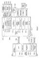
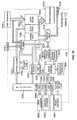
- FIG. 3is a block diagram of a functional architecture for a portable ventilator system in accordance with one or more embodiments of the invention.
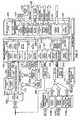
- FIG. 4is a block diagram of an electronic architecture for a portable ventilator system in accordance with one or more embodiments of the invention.
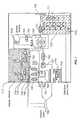
- FIG. 5is a block diagram of an electronic architecture for a docking cradle in accordance with one or more embodiments of the invention.
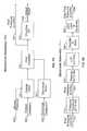
- FIGS. 6A and 6Bare block diagrams illustrating the general context of a software architecture for a portable ventilator system in accordance with one or more embodiments of the invention.
- FIG. 7is a pneumatic diagram of a portable ventilator in accordance with one or more embodiments of the invention.
- FIG. 8is a top level block diagram of an exhalation servo control system in accordance with one or more embodiments of the invention.
- FIG. 9Ais a block diagram of a mechanical assembly portion of an exhalation servo control system in accordance with one or more embodiments of the invention.
- FIG. 9Bis a block diagram of an electronic assembly portion of an exhalation servo control system in accordance with one or more embodiments of the invention.
- FIG. 9Cis a block diagram of a software control portion of an exhalation servo control system in accordance with one or more embodiments of the invention.
- FIG. 10is a block diagram of a blower assembly in accordance with one or more embodiments of the invention.
- FIG. 11is an exploded view of a blower assembly in accordance with one or more embodiments of the invention.
- FIG. 12is a perspective view of a pair of ROOTS-type blower impellers in accordance with one or more embodiments of the invention.
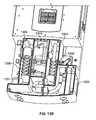
- FIGS. 13A and 13Bare views of a ventilator apparatus having silencer chambers with perforated tubes, in accordance with one or more embodiments of the invention.
- FIGS. 14A-14Dare various views of a ROOTS-type blower housing, illustrating graduated slots at the air outlets, in accordance with one or more embodiments of the invention.
- Embodiments of the inventionimplement a portable ventilator that uses a ROOTS-type blower operating in a variable speed mode as the breath delivery mechanism.
- a ROOTS-type bloweroperating in a variable speed mode as the breath delivery mechanism.
- novel sound muffling techniques and electronic control systemsallow the ventilator to be reduced in size to be comparable to a palmtop computer. Weight and power consumption may likewise be reduced.
- the ventilator of the present inventionprovides true, extended mobility to patients who require continuous breathing assistance, facilitating a significant improvement in their quality of life.
- a portable ventilator systemincludes a portable ventilator, a docking cradle and a monitor.
- the portable ventilatoris preferably, though not necessarily, a small, lightweight, self-contained life support device that is highly portable.
- the portable ventilatormay be placed into a docking cradle that acts as a simple structural support, possibly including a power supply and/or recharging system, or that expands the portable ventilators interface capabilities.
- the docking cradlemay also include a graphics monitor for enhanced display capabilities.
- the portable ventilatormay be packaged within a molded enclosure.
- the enclosureis co-molded with a soft rubber boot.
- the enclosureis configured to have a relatively compact form factor.
- an enclosure that is 10′′.times.6′′.times.2′′may contain the apparatus needed for a patient to receive proper ventilator support from a highly portable unit.
- Other embodimentsmay use enclosures with varying form factors.
- FIG. 1is a diagram illustrating a perspective view of the front face of a portable ventilator, in accordance with one or more embodiments of the invention.
- the pneumatic connections 101may be made on the left and right sides, e.g., below the centerline of ventilator enclosure 100 .
- Electrical interconnects 102may be made on the lower edge of the backside of enclosure 100 (e.g., to provide a cradle interface). The electrical interconnects may also be made on the left and/or right sides of enclosure 100 , e.g., above the centerline.
- the ventilator enclosuremay include a user interface 106 .
- user interface 106may be implemented relatively inexpensively in one embodiment with LEDs and a membrane switch panel.
- Another embodimentmay implement a graphical user interface 106 using a color LCD and touch screen.
- the top of ventilator enclosure 100may include a collapsible handle 103 that acts as a table stand when folded and collapses flush against the enclosure.
- Hand/shoulder strap connection points 104may be built into enclosure 100 .
- One or more embodimentsmay also implement a low-profile, dovetail-style mounting mechanism on the rear of enclosure 100 to facilitate pole, wall or bed-rail mounting without interfering with non-mounted desktop applications.
- battery port 105may be provided on enclosure 100 to accommodate an internal, removable battery pack.
- Battery port 105is preferably equipped with a latch and eject mechanism to insure a reliable connection when in use, and easy swapping of the removable battery pack, even when the enclosure is seated in a cradle (described below).
- Enclosure 100may be designed to drop into a docking cradle for raised support and/or to establish a connection between the portable ventilator and cradle electronics.
- An embodiment of a docking cradleis described below.
- FIGS. 2A and 2Bprovide a perspective views of the front and rear of a portable ventilator system, comprising a portable ventilator, a docking cradle and a monitor, in accordance with one or more embodiments of the invention.
- docking cradle 200may include a base 201 A and a cradle arm 201 B.
- a monitor 202may be attached to arm 201 B to provide a display for expanded ventilator monitoring capabilities.
- Portable ventilator enclosure 100is shown docked into base 201 A of cradle 200 .
- base 201 Ais designed to function as a simple table stand, without any internal power or logic components. However, in most embodiments, internal electronics are included to provide an intelligent docking station capable of supplying power and expanding the interface capabilities of the portable ventilator. In the latter case, base 201 A provides an electrical interconnection with the docked ventilator, e.g., through the lower, back edge of the ventilator. Arm 201 B may be removably attached to base 201 A to provide a support for the optional monitor 202 . Power and data cables between electronics in the cradle base 201 A and monitor 202 may be hidden within the structure of arm 201 B.
- Cradle 200may include a mechanical interlock to ensure that the docked ventilator cannot fall out. As with the ventilator enclosure 100 , cradle 200 may also incorporate a dovetail-style mounting mechanism to facilitate wall or bed-rail mounting. The docking cradle 200 and monitor 202 may each contain injection molded components.
- FIG. 3is a block diagram of a ventilator system functional architecture, in accordance with one or more embodiments of the invention.
- the ventilator pneumaticsmay be based on a ROOTS-type blower 300 that draws room air through inlet filter 310 and delivers pressurized gas through inspiratory port 311 to the patient.
- the pneumatic systemmay support both single limb and dual limb patient circuits, allowing exhalation valve 301 to be implemented either externally or internally with respect to ventilator enclosure 100 .
- Exhalation control port 302 and PEEP (positive end-expiratory pressure) control 303generate a pilot pressure that closes exhalation valve 301 during inspiration and opens it against a software controlled PEEP pilot pressure during exhalation.
- Scavenging port 316may be used to recycle or recirculate the compressed air that is not used by the patient during exhalation.
- the ventilator 100may deliver blended gas using an optional internal O 2 blender 304 .
- the blended gas delivery in inspiratory limb 312may be monitored via an external FIO 2 (fraction of inspired oxygen) sensor 305 coupled to FIO 2 interface 313 , and displayed on user interface 306 .
- the patient's blood O 2 levelmay also be monitored via an external pulse oxygen sensor 314 coupled to optional internal pulse oximeter 307 , and displayed on user interface 306 .
- the ventilator 100may drive an external nebulizer 309 via nebulizer drive port 315 for the delivery of aerosolized drugs to the patient while, at the same time, compensating for the added gas delivery.
- One or more embodimentsmay use a wye (“Y”) junction 325 to couple inspiratory limb 312 and expiratory limb 326 to the main ventilator tube to the patient.
- Airway and flow sensor lines 327 from wye junction 325enter ventilator enclosure 100 via sense ports 328 .
- Transducer (XDCR) manifold 329converts the airway and flow values from sense ports 328 into electrical sense signals for use in the ventilator control loop.
- the portable ventilator ( 100 )may operate from externally supplied DC power received through external power connector 317 (e.g., from external battery charger 318 A, external battery 318 B, AC/DC adapter 318 C, DC bus 318 D, etc.).
- a cradle interface 319may allow external power to be supplied to the ventilator without using a cable plug-in.
- the ventilator enclosure 100may be dropped into docking cradle 200 , where contacts in both devices automatically engage to provide a power path and/or data path.
- removable battery 321may be seated in removable battery bay 320 for use of the ventilator as a portable, stand-alone device.
- the ventilatormay be configured with an internal bridge battery ( 322 ) to provide continuous power to the ventilator during a swap of removable batteries ( 321 ).
- Battery charger 323may be used to charge removable battery 321 and/or bridge battery 322 when an external power source is connected to the ventilator enclosure 100 .
- An external removable battery charger ( 324 )may be used to charge extra batteries.
- docking cradle 200includes a ventilator interface 330 that mates with cradle interface block 319 of ventilator 100 to transfer power and provide electrical connections with interface electronics internal to cradle 200 .
- Optional internal AC/DC adapter 331 within cradle 200may provide a source of DC power to ventilator 100 via interface blocks 319 and 330 , as well as to the circuitry within cradle 200 and monitor 202 .
- Cradle 200may additionally or alternatively have a DC connector that receives DC power from an external source (e.g., sources 318 A- 318 D).
- Cradle 200may be used to expand the ventilator's interface capabilities to include, for example: a remote alarm/nurse call interface 332 with an output alarm cable; a remote access modem 333 ; an ISP/debug port 334 (service and maintenance port); an ETCO.sub.2 (end tidal carbon dioxide) monitor 336 coupled to an external ETCO.sub.2 sensor 335 ; a patient monitor interface 337 supporting patient monitor systems (such as HP Valuelink and SpaceLabs Flexport); a removable memory card slot 338 for supporting removable memory card 339 ; and a monitor interface/controller 340 .
- the removable memory card 339may be used to ease movement of information between the ventilator and a personal computer for data review and printing.
- Monitor 202coupled to arm 201 B of cradle 200 is an optional display unit capable of, for example, depicting waveforms, loops, and trend data continuously.
- the portable ventilator electronic architecturemay be divided into three major subsystems: a ventilator core subsystem, a user interface subsystem, and a power subsystem.
- Each subsystemmay include one or more software programmable microcontrollers distributed through the subassemblies along with a variety of digital, analog and power circuitry.
- Other embodimentsmay divide the electronic architecture along different lines, or not divide the architecture at all.
- FIG. 4illustrates one embodiment of the ventilator electronic architecture having a ventilator core (VC subsystem) 401 , a user interface (UI subsystem 400 and a power subsystem 402 .
- VC subsystemventilator core
- UI subsystem 400user interface
- power subsystem 402power subsystem
- VC subsystem 401includes electronics for implementing the core gas delivery functions of the portable ventilator.
- a software program running on the ventilator processor 443may control the overall ventilator core functionality by commanding and monitoring microcontrollers located within each functional subassembly or module. Each of these microcontrollers may run software programs dedicated to a specific task or tasks of the respective subassembly. In other embodiments, a single processor may be used to execute the tasks of multiple subassemblies.
- VC subsystem 401includes ventilator processor 443 in communication with respective processors within ROOTS-type blower module 444 , exhalation control module 454 , blender module 461 , and transducer module 470 . (In an alternate embodiment, two or more of modules 444 , 454 , 461 and 470 may be served by a single module processor.)
- blower processor 445may control the blower speed through software commutation of a brushless DC motor (BLDC 453 ) attached to the impellers of a ROOTS-type blower.
- Inverter 449may be used to convert the logic level commutation signals from blower processor 445 into high-power AC current to drive BLDC motor 453 .
- Multiple magnetic sensorse.g., analog Hall sensors 452
- An ADC (analog-to-digital converter) circuitmay be provided internal to or external to the blower processor IC for the purpose of sampling and converting sense signals, such as those from Hall sensors 452 , into digital values for blower processor 445 .
- Microphones 451 at the ROOTS-type blower intake and outlet portsmay be used to monitor the audible noise of the ROOTS-type blower apparatus.
- the microphone signalsare also sampled by the ADC circuit before being processed within blower processor 445 .
- Amplifier circuits 447 and 448may be used to amplify and filter the microphone and motor sense signals, respectively, prior to the ADC circuit.
- blower processor 445may generate “anti-noise” signals to cancel the blower noise.
- the anti-noise channels(e.g., one each for the noise at the intake and outlet ports of the blower) may be amplified via power amplifiers 446 that in turn drive a pair of speakers 450 located within the blower ductwork.
- the blower processor 445may include (either on-chip or off-chip) data SRAM, program FLASH memory, and calibration EEPROM.
- the FLASH and EEPROM memorymay be in-system programmable to facilitate manufacturing, service and field software updates.
- Blower processor 445may communicate with ventilator control processor 443 via a high-speed synchronous serial port (SSIO 479 ).
- SSIO 479high-speed synchronous serial port
- Blower processor 445may provide a mechanism for calibrating the electronics of blower module 444 , and for storing the calibration data within its EEPROM. Blower processor 445 may provide the additional ability to monitor the health of the electronics of blower module 444 and generate self-test feedback to ventilator processor 443 (or a separate test apparatus).
- exhalation processor 455may control multiple solenoid valves that generate and pass pilot pressure to the exhalation valve balloon diaphragm.
- Solenoid valve drivers 456translate the logic level control signals generated by exhalation processor 455 into high-power DC current to actuate exhalation control valve 459 and PEEP pilot valves 460 .
- Exhalation processor 455monitors PEEP pressure transducer 458 to enable closed loop control of PEEP pilot valves 460 .
- the analog signals from transducer 458maybe amplified and filtered by amplifier 457 prior to being A/D converted and sampled by the ADC circuit for exhalation processor 455 .
- exhalation processor 455may include (either on-chip or off-chip) data SRAM, program FLASH memory, and calibration EEPROM.
- the FLASH and EEPROM memorymay be in-system programmable to facilitate manufacturing, service and field software updates.
- Exhalation processor 455may communicate with ventilator control processor 443 via a high-speed synchronous serial port (SSIO 480 ).
- SSIO 480high-speed synchronous serial port
- Exhalation processor 455may provide a mechanism for calibrating the electronics of exhalation control module 454 , and for storing the calibration data within its EEPROM. Exhalation processor 455 may provide the additional ability to monitor the health of the electronics of exhalation control module 454 and generate self-test feedback to ventilator processor 443 (or a separate test apparatus).
- blender processor 462controls the flow of oxygen in the system, controls the optional nebulizer drive function, and monitors the external FIO.sub.2 sensor via FIO2 sensor interface 469 .
- Solenoid valve drivers 463translate the logic level control signals generated by blender processor 462 into high-power DC current to actuate blender valves 468 and nebulizer valve 467 .
- Blender processor 462monitors oxygen pressure transducer 465 to enable closed loop control of blender valves 468 .
- the analog signals from transducer 465 and interface 469maybe amplified and filtered by amplifier 464 and 466 , respectively, prior to being A/D converted and sampled by the ADC circuit for blender processor 462 .
- blender processor 462may include (either on-chip or off-chip) data SRAM, program FLASH memory, and calibration EEPROM.
- the FLASH and EEPROM memorymay be in-system programmable to facilitate manufacturing, service and field software updates.
- Blender processor 462may communicate with ventilator control processor 443 via a high-speed synchronous serial port (SSIO 481 ).
- SSIO 481high-speed synchronous serial port
- Blender processor 462may provide a mechanism for calibrating the electronics of blender module 461 , and for storing the calibration data within its EEPROM. Blender processor 462 may provide the additional ability to monitor the health of the electronics of blender module 461 and generate self-test feedback to ventilator processor 443 (or a separate test apparatus).
- pressure processor 471measures critical system pressures and manages periodic auto zero and sense line purge functions. Solenoid valve drivers 472 translate the logic level control signals generated by pressure processor 471 into high-power DC current to actuate autozero valves 473 and purge valves 474 . Pressure processor 471 monitors flow sensor pressure transducer 477 and airway and blower pressure transducers 478 .
- Amplifiers 476amplify and filter the sense signal outputs of transducers 477 and 478 before those sense signals are sampled and processed by pressure processor 471 .
- two parallel amplifiersmay be dedicated to flow sensor pressure transducer 477 .
- One amplifiermay provide a high-gain, narrow-range, offset-compensated flow trigger channel.
- the offset compensationis provided using a software-controlled DAC (digital-to-analog converter) circuit 475 .
- a second channelmay provide a lower gain amplifier to cover the full bi-directional dynamic range of flow into and out of the patient.
- Amplifiers 476also provide amplified airway gauge pressure and blower differential pressure signals.
- pressure processor 471may include (either on-chip or off-chip) data SRAM, program FLASH memory, and calibration EEPROM.
- the FLASH and EEPROM memorymay be in-system programmable to facilitate manufacturing, service and field software updates.
- Pressure processor 471may communicate with ventilator control processor 443 via a high-speed synchronous serial port (SSIO 482 ).
- SSIO 482high-speed synchronous serial port
- Pressure processor 471may provide a mechanism for calibrating the electronics of transducer module 470 , and for storing the calibration data within its EEPROM. Pressure processor 471 may provide the additional ability to monitor the health of the electronics of transducer module 470 and generate self-test feedback to ventilator processor 443 (or a separate test apparatus).
- User interface (UI) subsystem 400includes the electronics to create the interface to the device user and external peripherals.
- UI subsystem 400may provide the user with information, such as audible and visual feedback regarding the patient status, machine status, alarm conditions, and control settings.
- UI subsystem 400monitors the user inputs (e.g., knob and buttons) and communicates settings to ventilator processor 443 of ventilator core subsystem 401 via a serial channel (e.g., UART 442 ).
- a serial channele.g., UART 442
- UI subsystem 400monitors and controls power subsystem 402 , maintains device configuration and control settings in non-volatile memory, acts as a recorder of events and user actions, and communicates with any accessory devices (e.g., docking cradle 200 , internal pulse oximeter 307 , etc.).
- accessory devicese.g., docking cradle 200 , internal pulse oximeter 307 , etc.
- user interface processor 403executes a software program that controls the overall user interface functionality.
- the program FLASH memory associated with user interface processor 403may be in-system programmable to facilitate manufacturing, service and field software updates.
- certain taskssuch as refreshing displays and scanning keys, may be delegated to a programmable microcontroller and/or dedicated hardware controllers located within user interface subassemblies. The functionality of possible UI subassemblies is described below.
- the ventilator user interfacemay be implemented with a variety of display and input/output mechanisms.
- one user interface embodiment(labeled as high end user interface 404 ) utilizes a color LCD (liquid crystal display: e.g., TFT or VGA) graphics panel 429 and an analog touch screen overlay 431 to provide a flexible user interface with high information content.
- Interface 404is coupled to UI processor 403 via bus 435 .
- LCD controller 432may perform the time-intensive task of refreshing LCD 429 from a RAM image buffer (on-chip or off-chip) via a high-speed LVDS (low voltage differential signaling) interface 428 .
- the UI softwaremay restrict updates of the image buffer to time periods during which the display content actually changes.
- Backlight inverter 430powers the LCD backlight.
- Screen brightnessmay be controlled by the UI software using backlight DAC 433 .
- the touch screen ADC/controller 434performs scans of the touch screen overlay 431 , and provides the UI software with an interrupt and data during periods of touch activity.
- a low end user interface 408including, for example, a combination of dot matrix, seven-segment and/or discrete LEDs (represented as LED matrix 414 ) and a membrane key matrix 415 .
- LED matrix 414is driven by LED source drivers 416 and LED sink drivers 417 .
- IO (input/output) processor 410may perform the task of refreshing the LED matrix 414 from a RAM image buffer. The UI software may update the image buffer when its content changes. IO processor 410 also performs the task of scanning key matrix 415 and providing the UI software with an interrupt and data during periods of key activity.
- Both user interface optionsmay use a common user interface 409 that includes a knob (e.g., a rotary switch) 418 , one or more hard keys 419 for dedicated functions, status LEDs 420 and an audible software alarm speaker 421 .
- IO processor 410may track knob 418 and hard keys 419 , and provide the UI software with an interrupt and data during periods of knob and/or hard key activity.
- IO processor 410may also synthesize software alarms and control status LEDs 420 based on commands from the UI software with the aid of digital-to-analog (DAC) 422 .
- DACdigital-to-analog
- An optional internal pulse oximeter module 426whose external sensor is placed on the patient's finger, provides monitor data such as pulse rate and oxygen saturation level to user interface processor 403 .
- User interface processorcommunicates with module 426 over a serial interface such as UART 437 .
- Cradle interface 423includes a connector 424 , for electrically engaging a mating connector on the docking cradle, and a transceiver (e.g., ISO XCVR 425 ) to allow communication (e.g., via a serial UART interface 438 ) between the ventilator and the docking cradle electronics at moderate data rates.
- DC powermay also be transferred through this interface (see cradle power line 441 from connector 424 to power module 483 ) from the docking cradle to the ventilator.
- the ventilatormay also provide a remote alarm/nurse call signal through cradle interface 423 to the outside world.
- a non-volatile memory circuit(e.g., NAND FLASH 427 ) may be included in UI subsystem 400 for long term logging of ventilator events and control settings changes (like a “black box” recorder).
- User interface processor 403may write directly into non-volatile memory 427 via a parallel bus ( 436 ), for example.
- IO processor 410may also act as the supervisor for power subsystem 402 .
- IO processor 410may monitor all power inputs and power supply outputs, manage the selection of the active input power source (via power source switch matrix 489 ), and control the two internal battery chargers ( 485 and 487 ).
- IO processor 410may monitor the state of the “ON/OFF” and “ALARM SILENCE/RESET” hard keys and drive the “ON/OFF”, “VENT INOP”, “ALARM SILENCE”, “EXTERNAL POWER”, “BATTERY STATUS”, and “CHARGE STATUS” LEDs on common interface 409 .
- IO processor 410may act as the device watchdog. For example, in one embodiment, each subassembly must periodically report good health back to IO processor 410 . In turn, IO processor 410 must periodically report good health to alarm driver 412 of alarm system 407 . If alarm driver 412 fails to receive good health updates, then the audible hardware alarm (INOP) 413 and remote alarm/nurse call outputs ( 411 ) are activated. Alarm driver 412 may also trigger a device reset to attempt to restart the life support function.
- the common user interface 409 , low end user interface 408 and alarm system 407collectively comprise common interface 405 which communicates with UI interface 403 through serial interface UART 439 .
- Power module 483provides power to the ventilator and is connected thereto by bus 440 .
- the ventilatormay be powered from either an external DC source (e.g., external power source 492 or cradle interface 423 ) via connector 490 , or an internal source (e.g., removable battery 491 or bridge battery 486 ).
- Bridge battery 486may be sized to provide seamless operation of the ventilator while removable battery 491 is swapped from connector 488 .
- Two independent internal chargers( 485 and 487 ) may be included for purposes of maintaining charge on removable battery 491 and bridge battery 486 .
- Power supply 484may include several switching and/or linear power supplies to provide the DC voltages used throughout the ventilator system.
- FIG. 5is a block diagram of the electrical architecture for one embodiment of the docking cradle 200 .
- the docking cradleis divided into a basic module 500 and a full-featured module 501 .
- Basic module 500provides basic power and status indicators, as well as an alarm cable output.
- Full-featured module 501provides additional processing power, as well as further connection interfaces, monitoring capability and support for an additional display monitor.
- the division of featuresis shown to highlight the range of capabilities that may, but need not be, implemented within the docking cradle.
- the illustrated featuresare not intended to be exhaustive, nor do they represent required features. Different embodiments of the docking cradle may include different combinations and different numbers of features without departing from the scope of the invention.
- basic module 500includes cradle interface connector 503 , which mates electrically with cradle interface connector 424 of the ventilator.
- DC poweris supplied to the ventilator through power line 527 via AC/DC adapter 507 , which may receive AC power from an external source (e.g., from a cable attached to a wall outlet).
- AC/DC adapter 507may also provide DC power to full-featured module 501 via power monitor and controller block 506 .
- the remote alarm/nurse call outputs from the ventilator(see block 411 , FIG. 4 ) are made available for attachment of an external alarm cable (e.g., to plug into a wall jack or device in a hospital room) through remote alarm/nurse call interface 508 .
- a transceiver (XCVR) circuit 504may be implemented to facilitate communication with the ventilator over the cradle interface connector 503 .
- Transceiver circuit 504may communicate with cradle processor 509 over a serial interface, such as a UART interface 526 .
- Hardware driven status LEDs 505 in basic module 500provide basic device status, such as the active presence and/or health of AC/DC adapter 507 and of the connection with the ventilator.
- Full-featured module 501may be implemented to further expand the interface capabilities of the docking cradle to include, for example, the following options: support for an additional display monitor ( 502 ), memory expansion by the addition of one or more memory cards 575 (e.g., compact FLASH memory cards) in memory card slot(s) 514 , an additional patient monitoring interface 516 , an internal ETCO2 monitor 518 (coupled to an external ETCO2 sensor 512 ), and a modem 520 (e.g., for remote access via telephone).
- additional display monitor502
- memory expansion by the addition of one or more memory cards 575e.g., compact FLASH memory cards
- memory card slot(s) 514e.g., compact FLASH memory cards
- an additional patient monitoring interface 516e.g., an additional patient monitoring interface 516
- an internal ETCO2 monitor 518coupled to an external ETCO2 sensor 512
- modem 520e.g., for remote access via telephone.
- a software program executed by cradle processor 509controls the optional features of full-featured module 501 .
- Cradle processor 509may include (either on-chip or off-chip) data SRAM memory, program FLASH memory, and battery-backed SRAM.
- the FLASH memorymay be in-system programmable, via the ISP/debug interface (service port) 517 , to facilitate manufacturing, service and field software updates.
- power supply 521may be provided to perform DC-DC conversion to generate all of the supply voltages needed by the full-featured module circuitry.
- Software driven status LEDs 522may be included to show the on/off state and health of the module electronics.
- full-featured module 501may be equipped with monitor (PTM) controller 510 .
- Monitor controller 510includes an LCD controller 511 (assuming the monitor is an LCD monitor), backlight DAC 512 and touch screen ADC 513 .
- LCD controller 511supplies data and control signals to LCD panel 523 over LCD bus 528 and control (CTL) bus 529 , respectively; backlight DAC drives backlight inverter circuit 524 ; and touch screen ADC 513 controls touch screen panel 525 , as well as receiving touch screen data, over TS bus 530 .
- additional or different featuresmay be embodied within full-featured module 501 .
- the ventilator and docking cradlecontain embedded software (and/or firmware) that control the respective hardware and determine the operating characteristics of the system. This software may be split between multiple processors distributed throughout the system on various subassemblies.
- FIG. 6is a block diagram illustrating the context of the general software architecture of a ventilator system, in accordance with one or more embodiments of the invention.
- the software for the ventilator systemis distributed among the following processors: user interface processor 403 , IO processor 410 , ventilation processor 443 , blender processor 462 , exhalation processor 455 , pressure processor 471 , blower processor 445 , and cradle processor 509 .
- processorsuser interface processor 403 , IO processor 410 , ventilation processor 443 , blender processor 462 , exhalation processor 455 , pressure processor 471 , blower processor 445 , and cradle processor 509 .
- Various functions of the software executed by those respective processorsare described below. The functions described are presented for illustrative purposes only and should not be considered as either the only nor as required functions for all embodiments.
- the software running on each processorwill be referred to with reference to the name of the processor (i.e., the software executing on the user interface processor is referred to as the user interface software, the software running on the blender processor is referred to as the blender software, etc.).
- the user interface software(executing on user interface processor 403 ) may be configured to communicate with IO processor 410 (via bus 439 , as shown in FIG. 4 ) and cradle processor 509 , as well as to send ventilation control data (e.g., settings and alarm limits) to ventilation processor 443 .
- the user interface softwaremay store application code received from cradle processor 509 into FLASH memory 427 , and update application code for 10 processor 410 , ventilation processor 443 , blender processor 462 , exhalation processor 455 , pressure processor 471 and blower processor 445 .
- the user interface softwaremay also store trend data, vent settings and user configuration data in non-volatile RAM (NVR) 601 , and, with the aid of real-time clock 602 , may log all events, such as control changes, alarms and failures, in the “black box” portion of FLASH memory 427 .
- the user interface softwaredrives the LCD user interface (LCD 429 , touch panel 431 and backlight 433 ), for example, to display alarm data and/or monitored data received from ventilation processor 443 .
- the IO software(executing on IO processor 410 ) may be configured to communicate with user interface processor 403 to provide an intelligent controller for attached peripheral circuits and devices.
- the IO softwaremay provide low level drivers for status LEDs 420 , common buttons (or keys) 419 , knob 418 and speaker 421 .
- the IO softwaremay be configured to refresh LED matrix 414 , scan key matrix 415 , and control the power switch matrix 489 and battery charger(s) 603 ( 485 , 487 ).
- the ventilation software(executing on ventilation processor 443 ) may be configured to control primary functions, such as the generation of breaths, implementation of the pressure servo, and sequencing of maneuvers (e.g., nebulizer activation, I-hold (inhalation hold), E-hold (exhalation hold), etc.).
- the ventilation softwaremay also be configured to compute monitored parameters, compare monitored values to alarm limits, and schedule auto zero functions for pressure processor 471 .
- the blender software(executing on blender processor 462 ) may be configured to control nebulizer valve 467 and implement the blending servo to control blend valves 468 .
- the blender softwaremay also monitor and calibrate the O.sub.2 transducer 465 , manage calibration of the FIO.sub.2 sensor 469 and forward FiO.sub.2 data to ventilation processor 443 .
- the exhalation software(executing on exhalation processor 455 ) may be configured to implement the PEEP servo for control of PEEP in-valve 604 and PEEP out-valve 605 based on the input from pilot pressure transducer 458 .
- the exhalation softwaremay also control exhalation valve 459 and manage calibration of the pilot pressure transducer and the PEEP servo.
- the pressure software(executing on pressure processor 471 ) may be configured to provide calibrated trigger pressure readings and flow sensor pressure readings from flow transducer 477 , calibrated blower differential pressure readings from blower transducer 607 and calibrated airway pressure readings from airway transducer 606 to ventilation processor 443 .
- the pressure softwaremay also implement auto zero and purge functions with auto zero valves 473 and purge valves 474 .
- the blower software(executing on blower processor 445 ) may be configured to implement the speed servo and commutate the blower motor 453 .
- the blower softwaremay also calibrate the motor position sensors (e.g., Hall sensors 452 ) and compute rotor position and speed from the outputs of the motor position sensors 452 .
- the blower softwaremay also implement active braking of motor 453 and active sound canceling (e.g., using inputs from microphones 451 and generating anti-noise outputs via speakers 450 .
- the cradle software(executing on cradle processor 509 ) may be configured to communicate with user interface processor 403 , and to display ventilation data (e.g., waves, loops, data, summary and trends) on LCD display 523 .
- the cradle softwaremay also be configured to store trend data in non-volatile RAM (NVR) 600 and print images on memory card 575 .
- the cradle softwaremay collect ETCO2 data from ETCO2 monitor 518 and transmit that data to the ventilator via user interface processor 403 . Additionally, patient data and alarms may be forwarded to other patient monitor systems (e.g., via port 516 ).
- the ventilator pneumaticscomprise several electromechanical subassemblies in one or more embodiments of the invention. Ventilating functionality is provided by computer control of the pneumatic functions of those electromechanical subassemblies.
- FIG. 7is a pneumatic diagram of one embodiment if the ventilator.
- ROOTS-type blower 702driven for example by a brushless DC motor, is a rotary positive displacement machine that adds energy to the gas mixture and supplies gas to the patient at the desired flow and pressure.
- ROOTS-type blower 702may be characterized according to speed, flow, differential pressure and the associated flow data stored in electronic memory for use by ventilator processor 443 in alternately accelerating and decelerating the blower to effect inspiration and permit exhalation.
- Analog position sensorse.g., Hall sensors
- blower processor 445may compute the rotational speed of ROOTS-type blower 702 .
- Differential pressure transducer 703measures pressure across the blower.
- the ventilator processor 443working in conjunction with blower processor 445 , may adjust the blower speed throughout the inspiratory phase to obtain the desired flow, volume and pressure.
- Solenoid valves 704 and 705provide auto-zero capability for the differential pressure transducer 703 .
- Silencer chamber 706 on the gas outlet side of ROOTS-type blower 702reduces blower noise.
- the gasthen travels through bias valve 707 , set, for example, on or about 5 cmH2O.
- Patient flow transducer 708a fixed orifice differential pressure type transducer, measures the flow to and from the patient.
- Overpressure relief valve 709 and sub-ambient relief valve 710are internal and provide mechanical fail-safes to insure patient safety in the event of major ventilator malfunction.
- MIP/NIF lockout coil 711is included in sub-ambient relief valve 710 to prevent opening of the valve during maximum inspiratory pressure (MIP) procedures.
- Pressure transducer module 712provides the basic pressure measuring capabilities of the system. For example, three Piezo-resistive pressure transducers form flow sensor differential pressure transducer 713 to measure differential pressure across patient flow transducer 708 and an airway gauge pressure transducer 714 to gauge the pressure at the patient airway. Solenoid valves 715 and 716 provide auto-zero capability for flow sensor differential pressure transducer 713 , while valves 717 and 718 periodically send dry gas from the blower outlet through the patient flow transducer sense lines as part of a purge cycle.
- Exhalation control module 719allows the patient to exhale in accordance with the desired PEEP.
- exhalation control solenoid 720feeds gas pressure from the blower outlet to the balloon diaphragm of exhalation valve 721 , which closes the exhalation valve.
- pilot pressure from pilot pressure accumulator 722is fed to the balloon, which establishes the PEEP level.
- the pilot pressure in accumulator 722is controlled through pulse-width modulation (PWM) of pilot-in solenoid valve 723 and pilot-out solenoid valve 724 , using feedback from pilot pressure transducer 725 .
- PWMpulse-width modulation
- Oxygen blending and nebulizer driveare controlled in blender module 726 .
- Pressurized gasis received from an external source, filtered, and fed into the chambers of noise attenuation system 701 under the PWM control of solenoid valves 727 , 728 , 729 and 730 having associated orifices.
- Each solenoid valve orificemay be characterized during initial assembly, and the associated flow data may be stored in electronic memory on a PCB within module 726 .
- O 2 pressure transducer 731measures the valve inlet pressure. Using inlet pressure, the stored orifice characterizations, and PWM, the blender controller can deliver the range of oxygen flow desired.
- Nebulizer drive solenoid valve 732 and its associated orificemay deliver content, such as aerosolized medication, to the drive port of valves 727 - 730 during the inspiratory phase.
- the quantity of contentmay be, for example, on or about 6 lpm of oxygen flow.
- System softwaremay adjust the delivery of oxygen and volume to compensate for the added nebulizer flow.
- variable speed ROOTS-type blower 702is alternately accelerated and decelerated by ventilator processor 443 as necessary to effect inspiration and expiration.
- ROOTS-type blower 702is maintained by ventilator processor 443 at a relatively constant speed, generating a relatively constant flow of gas at a flow rate and pressure suitable for ventilating the lungs of a patient.
- a downstream flow control valveis utilized to control the flow of gas to the patient, opening to effect inspiration and closing to permit exhalation.
- the unique pressure and flow output of each ROOTS-type blower 702need not be measured during production and no individualized blower characterization data need be stored for use by the ventilator processor 443 .
- One or more embodiments of the inventionimplement an exhalation control servo to generate an actual PEEP pressure from a desired PEEP pressure value.
- the desired PEEP pressure valueis a digital value representative of a PEEP pressure.
- the actual PEEP pressureis a controlled force per unit area generated from the blower pressure of ROOTS-type blower 702 .
- the exhalation servocomprises electromechanical apparatus for achieving this conversion from the digital domain to the pneumatic domain.
- FIG. 8is a block diagram showing an exhalation servo loop, in accordance with an embodiment of the invention.
- the exhalation control servo of FIG. 8includes a software control block 800 , a mechanical assembly 801 and an electrical assembly 802 .
- software control block 800receives the digital desired PEEP value 804 (e.g., from ventilator processor 443 ) and a digital value of the current raw pilot pressure 808 , and generates a charge command 805 for increasing the output pressure of the servo loop and a discharge command 806 for reducing the output pressure.
- Commands 805 and 806are in electrical form (e.g., digital).
- Mechanical assembly 801receives the charge and discharge commands ( 805 , 806 ) from software control 800 , as well as a physical blower pressure 803 , in pneumatic form. Mechanical assembly 801 applies blower pressure 803 in accordance with the charge and discharge commands to generate a pilot pressure feedback value 807 and actual PEEP value 809 , both in pneumatic form. Electronic assembly 802 transforms pilot pressure 807 into raw pilot pressure signal 808 , in digital form for processing by software control 800 .
- FIG. 9Ais a block diagram of mechanical assembly 801 , in accordance with an embodiment of the invention.
- charge command 805is applied to charge valve 723 to control the amount of blower pressure 803 released into pilot chamber 722 .
- Discharge command 806is applied to discharge vale 724 to control the release of pressure from pilot chamber 722 .
- charge command 805 and discharge command 806are implemented as PWM signals.
- Pilot chamber 722accumulates the pressure effects of opening and closing valves 723 and 724 . The accumulated pressure is output as pilot pressure 807 .
- Chamber 900may embody the balloon diaphragm of the exhalation control valve, which asserts the actual PEEP pressure 809 .
- FIG. 9Bis a block diagram of an embodiment of electronic assembly 802 .
- the pilot pressure 807is converted into pilot pressure sense signal 901 by pressure transducer 714 .
- Pre-amplifier 902amplifies pilot pressure sense signal 901 and low-pass filter 903 removes any noise and upper harmonics in the amplified signal.
- the amplified and filtered sense signalis then sampled by sample-and-hold circuit 904 and subsequently converted into the digital raw pilot pressure value 808 in ADC block 905 .
- FIG. 9Cis a block diagram of an embodiment of software control block 800 .
- the desired PEEP value 804is applied to a function to generate desired pilot pressure value 907 .
- the function implemented within block 906may be a simple table look-up based on known (i.e., calibrated) values of pilot pressure for a given PEEP value. Alternatively, that function may be a mathematical model that approximates the inverse of the relationship between a pilot pressure input into chamber 900 and the PEEP value that results.
- Digital low-pass filter 908receives raw pilot pressure signal 808 and bandlimits that signal to maintain a desired servo loop response.
- Block 909implements a mathematical function that approximates the inverse of the characteristics of the transducer in block 714 . Any variance in pilot pressure values due to the behavior of the transducer may be corrected by block 909 .
- the mathematical model for block 909may be created by calibrating the transducer during production and storing raw and actual pilot pressure values. A mathematical equation may then be constructed to approximately reverse the effects of the transducer by determining coefficients for the equation through the application of least squares curve fitting or similar techniques on the calibration data.
- the desired pilot pressure 907 and the actual pilot pressure 910are compared to determine an error value, and that error value is applied to a control algorithm (e.g., a PI or PID algorithm) to generate charge command 805 and discharge command 806 .
- a control algorithme.g., a PI or PID algorithm
- the binary states of the charge and discharge commandsare determined at periodic intervals. If the measured pilot pressure exceeds the desired pilot pressure by a threshold amount, then the discharge command is asserted during that interval, whereas if the measured pilot pressure falls below the desired pilot pressure by more than a threshold amount, the charge command is asserted during that interval. When the measured pilot pressure resides within the threshold range of the desired pilot pressure, neither command is asserted (maintain status quo for current interval).
- the present inventioninvolves the precision speed control of an electric motor that may be used to drive a compressor in a mechanical ventilator.
- Mechanical ventilatorsmay have various modes of operation, e.g., pressure control and volume control.
- One common thread amongst most mechanical ventilatorsis that the desired operating mode is achieved by controlling the gas flow rate produced by the gas compressor.
- An example of a suitable compressor control system for a blower assemblyis further described in U.S. patent application Ser. No. 10/847,693, filed May 18, 2004, the specifications and figures of which are herein incorporated by reference.
- the compressor motoris a brushless DC (BLDC) motor driving a ROOTS-type blower used as a compressor in a portable mechanical ventilator.
- the flow rate and pressure provided by the compressorare controlled by the speed of the BLDC motor.
- BLDCbrushless DC
- embodiments of the present inventionmay employ analog sensors (e.g., analog Hall effect sensors, anisotropic magneto-resistive (AMR) sensors, etc.) to provide continuous rotor position and speed feedback for closed loop control.
- analog sensorse.g., analog Hall effect sensors, anisotropic magneto-resistive (AMR) sensors, etc.
- FIG. 10is a block diagram of a motor/compressor system in accordance with an embodiment of the present invention.
- the motor/compressor systemcomprises ROOTS-type blower 1002 coupled to BLDC motor 1004 .
- Gasi.e., air
- the air from inlet 1008is compressed by ROOTS-type blower 1002 , and then passed to the patient and/or other sections of the mechanical ventilator through outlet 1010 .
- Fluid communication pathsare provided from the input of ROOTS-type blower 1002 to solenoid valve 1012 , and from the output of ROOTS-type blower 1002 to solenoid valve 1014 .
- Ambient air pressureis also channeled to solenoid valves 1012 and 1014 via ambient inlets 1016 and 1018 , respectively.
- the output fluid communication channels of solenoid valves 1012 and 1014are provided to blower differential pressure transducer 1040 to convert the pressure differential between the two channels into an electrical signal representative of that pressure differential.
- transducer 1040measures the difference between the output pressure and input pressure of ROOTS-type blower 1002 .
- transducer 1040can also measure the pressure difference between the two ambient pressure inlets during an “auto-zero” phase of transducer 1040 .
- Processor 1020provides control of solenoid valves 1012 and 1014 , with solenoid drivers 1032 transforming the digital control signals from processor 1020 into power DC signals capable of driving the solenoid valves.
- Absolute pressure transducer 1022 and temperature transducer 1024generate electrical signals representing the absolute pressure level and the temperature.
- Each of transducers 1022 , 1024 and 1040are coupled to transducer (XDCR) interface block 1026 , which may provide signal amplification and filtering of the analog signals that are then provided to A/D (analog-to-digital) converter circuit 1038 .
- A/D converter 1038transforms the analog signals into digital values that may be processed by processor 1020 .
- Processor 1020also has the following associated circuitry: flash memory 1048 , JTAG test circuitry 1046 , random access memory (RAM) 1044 , and UARTs (universal asynchronous receiver-transmitters) 1042 and 1036 .
- External JTAG connector 1050is coupled to JTAG circuit 1046 to facilitate hardware tests and debugging in accordance with the JTAG standard.
- Telemetry connector 1052is coupled to UART 1042 for the transmission of measured ventilator parameters to a remote system, e.g., for monitoring purposes.
- Communication and power connector 1054is coupled to UART 1036 for facilitating further external communication with the ventilator system, e.g., for operational testing and control.
- Connector 1054also provides any necessary power signals to the motor/compressor system (e.g., 3.3, 5.0 and/or 15 VDC (volts DC)).
- Analog sensors 1006are arranged on a PC board in a circular pattern perpendicular to the rotor shaft of BLDC motor 1004 and adjacent to a two-pole magnet attached to the end of the rotor shaft. Analog sensors 1006 provide measurements needed for computation of BLDC rotor position. The analog outputs of sensors 1006 are passed through sensor interface 1028 (e.g., for amplification and filtering), and then into A/D converter circuit 1038 , where the analog sensor signals are converted into digital values for processing within processor 1020 .
- sensor interface 1028e.g., for amplification and filtering
- Processor 1020executes software instructions to implement certain elements of the motor/compressor control loop.
- Processor 1020may be implemented, for example, with a general purpose processor or with a digital signal processor (DSP).
- DSPdigital signal processor
- Other embodimentsmay implement the functionality of processor 1020 in firmware (e.g., instructions stored in an EPROM) or as equivalent logic in a hardware device (e.g., an ASIC (application specific integrated circuit) or an FPGA (field programmable gate array)).
- firmwaree.g., instructions stored in an EPROM
- ASICapplication specific integrated circuit
- FPGAfield programmable gate array
- Processor 1020receives the digitized sensor signals and pressure measurements via A/D converter block 1038 (values may use RAM 1044 for temporary storage), and determines an appropriate speed control value based upon the control process implemented (e.g., pressure control or volume control). Processor 1020 also generates the appropriate commutation control signals given the current commutation state, and modulates the pulse widths of those commutation control signals based on the speed control value. The modulated commutation control signals are provided to three phase inverter 1030 .
- Three-phase inverter 1030generates drive signals for the individual stator coils in BLDC motor 1004 , as previously described.
- the systemmay also include a current limit circuit 1034 coupled to three-phase inverter block 1030 .
- FIG. 11is an exploded view of the physical structure of a ROOTS-type blower, in accordance with an embodiment of the invention.
- structure 1100includes the BLDC motor.
- the stator of the BLDC motorsurrounds hollow bore 1108 , into which a rotor 1101 is inserted during manufacturing.
- Rotor 1101spins under the influence of the energized stator coils within the BLDC motor.
- Stabilizer 1102supports the rotating axis shared by rotor 1101 and ROOTS-type blower impeller 1103 .
- the shared axisforces impeller 1103 to rotate when the BLDC motor forces rotor 1101 to rotate.
- Impeller 1103rotates within ROOTS-type blower housing 1104 , with one end of the impeller axis coupled to gears 1105 .
- a second impeller(not shown) is also coupled to gears 1105 such that the second impeller rotates in the opposite direction of impeller 1103 .
- the rotation of the impellersforces air to flow between the impellers with additional energy, creating pressure. Openings in either side of housing 1104 provide the air input and output paths.
- the elements of the blower assemblyare coupled to surrounding structures in the lateral direction by broad connectors 1106 , and in the longitudinal direction by long connectors 1107 .
- the increased size of those connectorsprovides greater support for the apparatus, while providing dampening of vibrations due to the motion of the blower apparatus.
- FIG. 12illustrates the interlocking nature of the ROOTS-type blower impellers 1103 and 1203 .
- the shared axis of impeller 1103 and rotor 1101is visible in this image, showing the mechanism by which the ROOTS-type blower impellers are driven.
- Engagement of gears 1201 and 1202provides the transfer of opposing rotational energy from the axis of impeller 1103 to the axis of impeller 1203 .
- ROOTS-type blowersare relatively noisy, and because embodiments of the invention are designed for use in close proximity to the patient, one or more methods and features for dampening the noise generated by the blower may be implemented in embodiments of the invention. Such methods and features may include forming the blower rotors with a helical twist (as shown in FIG. 12 ), and using multiple sound muffling techniques, such as the anti-noise cancellation methods described previously.
- embodiments of the inventionmay include the use of perforated tube mufflers, in which numerous perforations protrude from the body of each perforated tube at right angles in the form of small tubes, creating a longer effective muffling pathway capable of efficiently attenuating sound waves without concomitant increase in muffler weight and size.
- the perforated tube mufflersare preferably constructed of a lightweight polymer or other sturdy but lightweight material.
- FIG. 13Ashows a view of the pneumatic pathways and noise reduction chambers of one embodiment of the invention.
- airenters the ventilator through filtered inlet 1300 , and traverses a twisted pneumatic path until it reaches the bottom of silencer chamber 1303 .
- the airis directed into an inlet port of the ROOTS-type blower assembly 1302 .
- the compressed airis output from the ROOTS-type blower assembly into the upper portion of silencer chamber 1304 , and then directed on from the bottom ( 1301 ) of chamber 1304 .
- Silencer chambers 1303 and 1304each include two perforated muffler tubes 1305 and 1306 positioned in parallel, e.g., with one above the other.
- FIG. 13Billustrates the silencer chambers with the top tube ( 1305 ) removed, providing a clearer view of underlying tube 1306 .
- the input to each silencer chamberis through one end of tube 1305 , with the exit being through the opposing end of tube 1306 .
- the airmust therefore flow out of tube 1305 and in through tube 1306 .
- the pressure transients associated with compressor noiseare dampened by the resistance presented by the small tubular perforations. Further, the coherence of the noise pressure waves is disrupted by the forced traversal of multiple small pathways of varying lengths. The varying length pathways cause the air flow of the respective pathways to recombine out of phase with each other, diffusing the previously coherent noise. As a result, much of the compressor noise is attenuated during transit of the silencer chambers.
- Embodiments of the inventionmay also include graduated slots in the housing of the Roots blower which permit a smooth, gradual backflow of gas as the leading edge of the blower rotors approach the blower outlet port, thus reducing the typical Roots blower pulsing effect responsible for much of the noise.
- the graduated slots in the housing of the Roots blowermaximize noise reduction while minimizing the reduction in efficiency attendant upon permitting gradual backflow into the blower chambers during rotation.
- FIGS. 14A-14Dprovide different views of the Roots blower housing 1400 .
- Orifice 1401faces the direction of the BLDC motor, and receives the pair of impellers.
- two orificesare provided through which the axes of the impellers extend to engage gear structure 1105 perpendicular to the axis defined by orifice 1401 and opposing face 1402 , an air inlet 1403 and a compressed air output port 1404 are provided.
- the inlet and output portsare configured with an initial circular indentation 1405 , e.g., to receive a tubular air guide apparatus.
- an orifice 1406having a roughly triangular cross-section at the level of indentation 1405 , and a curved wing-shape where the triangular cut-out meets the dual-rounded chamber encompassing the rotating impellers.
- a groove 1407is formed on the inside of orifice 1406 roughly midway along the side of the triangle, aligned in the same plane as the stacking of the impellers. Grooves 1407 are deepest at the edge of triangular orifice 1406 , and gradually diminish to the level of the inner chamber away from orifice 1406 .
Landscapes
- Health & Medical Sciences (AREA)
- Engineering & Computer Science (AREA)
- Biomedical Technology (AREA)
- Public Health (AREA)
- General Health & Medical Sciences (AREA)
- Heart & Thoracic Surgery (AREA)
- Anesthesiology (AREA)
- Hematology (AREA)
- Life Sciences & Earth Sciences (AREA)
- Animal Behavior & Ethology (AREA)
- Pulmonology (AREA)
- Emergency Medicine (AREA)
- Veterinary Medicine (AREA)
- Mechanical Engineering (AREA)
- General Engineering & Computer Science (AREA)
- Medical Informatics (AREA)
- Power Engineering (AREA)
- Primary Health Care (AREA)
- Epidemiology (AREA)
- Surgery (AREA)
- General Business, Economics & Management (AREA)
- Nuclear Medicine, Radiotherapy & Molecular Imaging (AREA)
- Business, Economics & Management (AREA)
- Urology & Nephrology (AREA)
- Measuring And Recording Apparatus For Diagnosis (AREA)
- Percussion Or Vibration Massage (AREA)
- Control Of Positive-Displacement Air Blowers (AREA)
- Measurement Of The Respiration, Hearing Ability, Form, And Blood Characteristics Of Living Organisms (AREA)
- Control Of Positive-Displacement Pumps (AREA)
- Respiratory Apparatuses And Protective Means (AREA)
Abstract
Description
Claims (15)
Priority Applications (2)
| Application Number | Priority Date | Filing Date | Title |
|---|---|---|---|
| US11/445,724US8297279B2 (en) | 2003-08-04 | 2006-06-02 | Portable ventilator system |
| US11/979,142US8683997B2 (en) | 2003-08-04 | 2007-10-31 | Portable ventilator system |
Applications Claiming Priority (4)
| Application Number | Priority Date | Filing Date | Title |
|---|---|---|---|
| US49242103P | 2003-08-04 | 2003-08-04 | |
| US10/847,693US7607437B2 (en) | 2003-08-04 | 2004-05-18 | Compressor control system and method for a portable ventilator |
| US10/912,747US7188621B2 (en) | 2003-08-04 | 2004-08-04 | Portable ventilator system |
| US11/445,724US8297279B2 (en) | 2003-08-04 | 2006-06-02 | Portable ventilator system |
Related Parent Applications (2)
| Application Number | Title | Priority Date | Filing Date |
|---|---|---|---|
| US10/912,747DivisionUS7188621B2 (en) | 2003-08-04 | 2004-08-04 | Portable ventilator system |
| US11/979,142DivisionUS8683997B2 (en) | 2003-08-04 | 2007-10-31 | Portable ventilator system |
Related Child Applications (1)
| Application Number | Title | Priority Date | Filing Date |
|---|---|---|---|
| US11/979,142ContinuationUS8683997B2 (en) | 2003-08-04 | 2007-10-31 | Portable ventilator system |
Publications (2)
| Publication Number | Publication Date |
|---|---|
| US20070000490A1 US20070000490A1 (en) | 2007-01-04 |
| US8297279B2true US8297279B2 (en) | 2012-10-30 |
Family
ID=38229851
Family Applications (5)
| Application Number | Title | Priority Date | Filing Date |
|---|---|---|---|
| US10/912,747Expired - LifetimeUS7188621B2 (en) | 2003-08-04 | 2004-08-04 | Portable ventilator system |
| US11/445,762Expired - Fee RelatedUS8627819B2 (en) | 2003-08-04 | 2006-06-02 | Portable ventilator system |
| US11/445,724Expired - LifetimeUS8297279B2 (en) | 2003-08-04 | 2006-06-02 | Portable ventilator system |
| US11/712,929Expired - Fee RelatedUS8522780B2 (en) | 2003-08-04 | 2007-03-01 | Portable ventilator system |
| US11/979,142Active2027-01-29US8683997B2 (en) | 2003-08-04 | 2007-10-31 | Portable ventilator system |
Family Applications Before (2)
| Application Number | Title | Priority Date | Filing Date |
|---|---|---|---|
| US10/912,747Expired - LifetimeUS7188621B2 (en) | 2003-08-04 | 2004-08-04 | Portable ventilator system |
| US11/445,762Expired - Fee RelatedUS8627819B2 (en) | 2003-08-04 | 2006-06-02 | Portable ventilator system |
Family Applications After (2)
| Application Number | Title | Priority Date | Filing Date |
|---|---|---|---|
| US11/712,929Expired - Fee RelatedUS8522780B2 (en) | 2003-08-04 | 2007-03-01 | Portable ventilator system |
| US11/979,142Active2027-01-29US8683997B2 (en) | 2003-08-04 | 2007-10-31 | Portable ventilator system |
Country Status (8)
| Country | Link |
|---|---|
| US (5) | US7188621B2 (en) |
| EP (2) | EP2374490A2 (en) |
| JP (2) | JP2007501074A (en) |
| AU (2) | AU2004263115B2 (en) |
| BR (1) | BRPI0413275A (en) |
| CA (1) | CA2531926C (en) |
| ES (1) | ES2592262T3 (en) |
| WO (1) | WO2005013879A2 (en) |
Cited By (10)
| Publication number | Priority date | Publication date | Assignee | Title |
|---|---|---|---|---|
| WO2016209925A1 (en)* | 2015-06-22 | 2016-12-29 | Caire Inc. | Wearable oxygen generator and docking station enabling higher oxygen flow capacity |
| US9956371B2 (en) | 2015-03-24 | 2018-05-01 | Ventec Life Systems, Inc. | Ventilator with integrated cough-assist |
| US10773049B2 (en) | 2016-06-21 | 2020-09-15 | Ventec Life Systems, Inc. | Cough-assist systems with humidifier bypass |
| US10905837B2 (en) | 2015-04-02 | 2021-02-02 | Hill-Rom Services Pte. Ltd. | Respiratory therapy cycle control and feedback |
| US11191915B2 (en) | 2018-05-13 | 2021-12-07 | Ventec Life Systems, Inc. | Portable medical ventilator system using portable oxygen concentrators |
| WO2022013004A1 (en)* | 2020-07-13 | 2022-01-20 | Hamilton Medical Ag | Emergency ventilator with removable common cover for simultaneously covering filter and battery compartment |
| US11247015B2 (en) | 2015-03-24 | 2022-02-15 | Ventec Life Systems, Inc. | Ventilator with integrated oxygen production |
| WO2022043471A1 (en)* | 2020-08-31 | 2022-03-03 | Hamilton Medical Ag | Ventilator device having an input/output device locked on an inner functional arrangement |
| US11400247B2 (en) | 2016-12-22 | 2022-08-02 | Fisher & Paykel Healthcare Limited | Breathing assistance apparatus |
| US12440634B2 (en) | 2021-12-21 | 2025-10-14 | Ventec Life Systems, Inc. | Ventilator systems with integrated oxygen delivery, and associated devices and methods |
Families Citing this family (298)
| Publication number | Priority date | Publication date | Assignee | Title |
|---|---|---|---|---|
| US8932227B2 (en) | 2000-07-28 | 2015-01-13 | Lawrence A. Lynn | System and method for CO2 and oximetry integration |
| US9042952B2 (en)* | 1997-01-27 | 2015-05-26 | Lawrence A. Lynn | System and method for automatic detection of a plurality of SPO2 time series pattern types |
| US20060161071A1 (en)* | 1997-01-27 | 2006-07-20 | Lynn Lawrence A | Time series objectification system and method |
| US5915379A (en)* | 1997-03-14 | 1999-06-29 | Nellcor Puritan Bennett Incorporated | Graphic user interface for a patient ventilator |
| US20070191697A1 (en) | 2006-02-10 | 2007-08-16 | Lynn Lawrence A | System and method for SPO2 instability detection and quantification |
| US9521971B2 (en) | 1997-07-14 | 2016-12-20 | Lawrence A. Lynn | System and method for automatic detection of a plurality of SPO2 time series pattern types |
| US20080287756A1 (en)* | 1997-07-14 | 2008-11-20 | Lynn Lawrence A | Pulse oximetry relational alarm system for early recognition of instability and catastrophic occurrences |
| US9053222B2 (en)* | 2002-05-17 | 2015-06-09 | Lawrence A. Lynn | Patient safety processor |
| US20060195041A1 (en) | 2002-05-17 | 2006-08-31 | Lynn Lawrence A | Centralized hospital monitoring system for automatically detecting upper airway instability and for preventing and aborting adverse drug reactions |
| US6850788B2 (en) | 2002-03-25 | 2005-02-01 | Masimo Corporation | Physiological measurement communications adapter |
| DE10337138A1 (en)* | 2003-08-11 | 2005-03-17 | Freitag, Lutz, Dr. | Method and arrangement for the respiratory assistance of a patient as well as tracheal prosthesis and catheter |
| US7588033B2 (en)* | 2003-06-18 | 2009-09-15 | Breathe Technologies, Inc. | Methods, systems and devices for improving ventilation in a lung area |
| FR2858236B1 (en)* | 2003-07-29 | 2006-04-28 | Airox | DEVICE AND METHOD FOR SUPPLYING RESPIRATORY GAS IN PRESSURE OR VOLUME |
| US7607437B2 (en)* | 2003-08-04 | 2009-10-27 | Cardinal Health 203, Inc. | Compressor control system and method for a portable ventilator |
| US7527053B2 (en)* | 2003-08-04 | 2009-05-05 | Cardinal Health 203, Inc. | Method and apparatus for attenuating compressor noise |
| ES2592262T3 (en)* | 2003-08-04 | 2016-11-29 | Carefusion 203, Inc. | Portable respirator system |
| US8156937B2 (en)* | 2003-08-04 | 2012-04-17 | Carefusion 203, Inc. | Portable ventilator system |
| US8118024B2 (en)* | 2003-08-04 | 2012-02-21 | Carefusion 203, Inc. | Mechanical ventilation system utilizing bias valve |
| CN1905917B (en) | 2003-08-18 | 2011-08-03 | 门罗生命公司 | Method and device for non-invasive ventilation with nasal interface |
| CN1871611A (en) | 2003-11-12 | 2006-11-29 | 德雷格医疗系统股份有限公司 | Modular medical care system |
| US7802571B2 (en)* | 2003-11-21 | 2010-09-28 | Tehrani Fleur T | Method and apparatus for controlling a ventilator |
| EP1824542A1 (en)* | 2004-10-26 | 2007-08-29 | Map-Medizintechnologie GmbH | Apparatus for administering a breathable gas, and components thereof |
| DE102005010488A1 (en)* | 2005-03-04 | 2006-09-07 | Map Medizin-Technologie Gmbh | Apparatus for administering a breathing gas and method for adjusting at least temporarily alternating breathing gas pressures |
| DE102005032431B4 (en)* | 2005-03-15 | 2025-04-30 | Weinmann Emergency Medical Technology Gmbh + Co. Kg | Modular medical device |
| JP5057417B2 (en)* | 2005-05-30 | 2012-10-24 | ルネサスエレクトロニクス株式会社 | Semiconductor integrated circuit for liquid crystal display drive |
| PL3434332T3 (en)* | 2005-07-01 | 2024-05-06 | Fisher & Paykel Healthcare Limited | A breathing assistance apparatus with a manifold to add auxiliary gases to ambient gases |
| DE202005017045U1 (en) | 2005-07-21 | 2006-07-20 | Weinmann Geräte für Medizin GmbH & Co. KG | Device for supplying a breathing gas |
| US7958892B2 (en) | 2005-07-29 | 2011-06-14 | Resmed Limited | Air delivery system |
| US20070045152A1 (en)* | 2005-08-01 | 2007-03-01 | Resmed Limited | Storage system for an apparatus that delivers breathable gas to a patient |
| USD550360S1 (en)* | 2005-09-02 | 2007-09-04 | Airsep Corporation | Portable oxygen concentrator |
| JP2009508645A (en) | 2005-09-20 | 2009-03-05 | ルッツ フレイテッグ, | System, method and apparatus for assisting patient breathing |
| US7677246B2 (en)* | 2005-09-23 | 2010-03-16 | Ric Investments, Llc | Modular pressure support system |
| US7617824B2 (en)* | 2005-12-08 | 2009-11-17 | Ric Investments, Llc | Ventilator adaptable for use with either a dual-limb circuit or a single-limb circuit |
| WO2007102866A2 (en) | 2005-12-08 | 2007-09-13 | Ric Investments, Llc | Ventilator adaptable for use with either a dual-limb or a single-limb circuit |
| US7668579B2 (en) | 2006-02-10 | 2010-02-23 | Lynn Lawrence A | System and method for the detection of physiologic response to stimulation |
| US8640697B2 (en) | 2006-02-17 | 2014-02-04 | Resmed Limited | Combination enhanced therapy |
| USD546950S1 (en)* | 2006-03-14 | 2007-07-17 | Bunnell, Inc. | Ventilator chassis |
| BRPI0709500A2 (en)* | 2006-04-10 | 2011-07-26 | Aeiomed Inc | apparatus for providing positive airway pressure for the treatment of sleep apnea, chronic pulmonary obstruction and snoring, and method for providing positive air pressure for the treatment of sleep apnea, chronic pulmonary obstruction and snoring |
| US8021310B2 (en)* | 2006-04-21 | 2011-09-20 | Nellcor Puritan Bennett Llc | Work of breathing display for a ventilation system |
| US7909033B2 (en) | 2006-05-03 | 2011-03-22 | Comedica Incorporated | Breathing treatment apparatus |
| JP5191005B2 (en) | 2006-05-18 | 2013-04-24 | ブリーズ テクノロジーズ, インコーポレイテッド | Method and device for tracheostomy |
| DE102007026565A1 (en)* | 2006-06-09 | 2007-12-27 | ResMed Ltd., Bella Vista | Accessory devices for portable positive airway device and method of use thereof |
| WO2007149446A2 (en)* | 2006-06-16 | 2007-12-27 | Aeiomed, Inc. | Modular positive airway pressure therapy apparatus and methods |
| EP2068992B1 (en) | 2006-08-03 | 2016-10-05 | Breathe Technologies, Inc. | Devices for minimally invasive respiratory support |
| US7616508B1 (en)* | 2006-08-10 | 2009-11-10 | Actel Corporation | Flash-based FPGA with secure reprogramming |
| US8051854B2 (en)* | 2006-09-15 | 2011-11-08 | Comedica Incorporated | Continuous high-frequency oscillation breathing treatment apparatus |
| WO2008036361A2 (en) | 2006-09-19 | 2008-03-27 | Kci Licensing Inc. | Reduced pressure treatment system having blockage clearing and dual-zone pressure protection capabilities |
| US8061360B2 (en)* | 2006-09-19 | 2011-11-22 | Kci Licensing, Inc. | System and method for locating fluid leaks at a drape of a reduced pressure delivery system |
| US8366690B2 (en) | 2006-09-19 | 2013-02-05 | Kci Licensing, Inc. | System and method for determining a fill status of a canister of fluid in a reduced pressure treatment system |
| US9161696B2 (en) | 2006-09-22 | 2015-10-20 | Masimo Corporation | Modular patient monitor |
| US8840549B2 (en) | 2006-09-22 | 2014-09-23 | Masimo Corporation | Modular patient monitor |
| US7784461B2 (en) | 2006-09-26 | 2010-08-31 | Nellcor Puritan Bennett Llc | Three-dimensional waveform display for a breathing assistance system |
| US20080072902A1 (en)* | 2006-09-27 | 2008-03-27 | Nellcor Puritan Bennett Incorporated | Preset breath delivery therapies for a breathing assistance system |
| US8210174B2 (en) | 2006-09-29 | 2012-07-03 | Nellcor Puritan Bennett Llc | Systems and methods for providing noise leveling in a breathing assistance system |
| US7891354B2 (en)* | 2006-09-29 | 2011-02-22 | Nellcor Puritan Bennett Llc | Systems and methods for providing active noise control in a breathing assistance system |
| US20080078390A1 (en)* | 2006-09-29 | 2008-04-03 | Nellcor Puritan Bennett Incorporated | Providing predetermined groups of trending parameters for display in a breathing assistance system |
| US7849250B2 (en)* | 2006-10-31 | 2010-12-07 | Sonosite, Inc. | Docking station with hierarchal battery management for use with portable medical equipment |
| JP2011502547A (en)* | 2006-11-01 | 2011-01-27 | フィッシャー、ジョセフ | Portable life support device |
| US7779841B2 (en)* | 2006-11-13 | 2010-08-24 | Carefusion 2200, Inc. | Respiratory therapy device and method |
| US8371299B2 (en)* | 2007-04-19 | 2013-02-12 | Respironics Respiratory Drug Delivery | Ventilator aerosol delivery |
| US9050434B2 (en)* | 2007-05-18 | 2015-06-09 | Comedica Incorporated | Lung therapy device |
| WO2008144589A1 (en) | 2007-05-18 | 2008-11-27 | Breathe Technologies, Inc. | Methods and devices for sensing respiration and providing ventilation therapy |
| US8656913B2 (en)* | 2007-06-05 | 2014-02-25 | Allied Healthcare Products, Inc. | Ventilator apparatus |
| US20090005651A1 (en)* | 2007-06-27 | 2009-01-01 | Welch Allyn, Inc. | Portable systems, devices and methods for displaying varied information depending on usage circumstances |
| EP3871722A1 (en) | 2007-07-18 | 2021-09-01 | Vapotherm, Inc. | System for delivering a heated and humidified gas |
| EP2203206A4 (en) | 2007-09-26 | 2017-12-06 | Breathe Technologies, Inc. | Methods and devices for treating sleep apnea |
| EP2200686A4 (en) | 2007-09-26 | 2017-11-01 | Breathe Technologies, Inc. | Methods and devices for providing inspiratory and expiratory flow relief during ventilation therapy |
| US8905023B2 (en) | 2007-10-05 | 2014-12-09 | Vapotherm, Inc. | Hyperthermic humidification system |
| US8511305B2 (en)* | 2007-10-29 | 2013-08-20 | Smiths Medical Asd, Inc. | Redundant power control for respiratory system heaters |
| US8365727B2 (en) | 2007-11-19 | 2013-02-05 | Carefusion 2200, Inc. | Respiratory therapy system with electromechanical driver |
| US20090133695A1 (en)* | 2007-11-27 | 2009-05-28 | Rao Chamkurkishtiah P | Mechanical ventilator system |
| US7997885B2 (en)* | 2007-12-03 | 2011-08-16 | Carefusion 303, Inc. | Roots-type blower reduced acoustic signature method and apparatus |
| AU2009205945A1 (en)* | 2008-01-18 | 2009-07-23 | Breathe Technologies, Inc. | Methods and devices for improving efficacy of non-invasive ventilation |
| US20090205493A1 (en)* | 2008-02-20 | 2009-08-20 | Thompson Loren M | Method of removing water from an inlet region of an oxygen generating system |
| US20090205494A1 (en)* | 2008-02-20 | 2009-08-20 | Mcclain Michael S | Single manifold assembly for oxygen-generating systems |
| US7722698B2 (en)* | 2008-02-21 | 2010-05-25 | Delphi Technologies, Inc. | Method of determining the purity of oxygen present in an oxygen-enriched gas produced from an oxygen delivery system |
| US20090211443A1 (en)* | 2008-02-21 | 2009-08-27 | Youngblood James H | Self-serviceable filter for an oxygen generating device |
| US8075676B2 (en) | 2008-02-22 | 2011-12-13 | Oxus America, Inc. | Damping apparatus for scroll compressors for oxygen-generating systems |
| US20090214393A1 (en)* | 2008-02-22 | 2009-08-27 | Chekal Michael P | Method of generating an oxygen-enriched gas for a user |
| US20090229460A1 (en)* | 2008-03-13 | 2009-09-17 | Mcclain Michael S | System for generating an oxygen-enriched gas |
| US8888711B2 (en)* | 2008-04-08 | 2014-11-18 | Carefusion 203, Inc. | Flow sensor |
| US8776793B2 (en) | 2008-04-18 | 2014-07-15 | Breathe Technologies, Inc. | Methods and devices for sensing respiration and controlling ventilator functions |
| WO2009129506A1 (en) | 2008-04-18 | 2009-10-22 | Breathe Technologies, Inc. | Methods and devices for sensing respiration and controlling ventilator functions |
| US8251876B2 (en) | 2008-04-22 | 2012-08-28 | Hill-Rom Services, Inc. | Breathing exercise apparatus |
| JP5474937B2 (en) | 2008-05-07 | 2014-04-16 | ローレンス エー. リン, | Medical disorder pattern search engine |
| US8457706B2 (en)* | 2008-05-16 | 2013-06-04 | Covidien Lp | Estimation of a physiological parameter using a neural network |
| US8539951B1 (en) | 2008-05-27 | 2013-09-24 | Trudell Medical International | Oscillating positive respiratory pressure device |
| US8713697B2 (en) | 2008-07-09 | 2014-04-29 | Lennox Manufacturing, Inc. | Apparatus and method for storing event information for an HVAC system |
| US20100013641A1 (en)* | 2008-07-17 | 2010-01-21 | Reed Chad M | System for providing remote signals from a patient monitor |
| CN102196837B (en) | 2008-08-22 | 2015-09-09 | 呼吸科技公司 | Methods and devices for providing mechanical ventilation utilizing an open airway interface |
| US8424520B2 (en) | 2008-09-23 | 2013-04-23 | Covidien Lp | Safe standby mode for ventilator |
| US20100071695A1 (en)* | 2008-09-23 | 2010-03-25 | Ron Thiessen | Patient wye with flow transducer |
| US8302600B2 (en)* | 2008-09-30 | 2012-11-06 | Nellcor Puritan Bennett Llc | Battery management for a breathing assistance system |
| US8302602B2 (en) | 2008-09-30 | 2012-11-06 | Nellcor Puritan Bennett Llc | Breathing assistance system with multiple pressure sensors |
| US10252020B2 (en) | 2008-10-01 | 2019-04-09 | Breathe Technologies, Inc. | Ventilator with biofeedback monitoring and control for improving patient activity and health |
| CN102186524B (en)* | 2008-10-16 | 2014-07-09 | 皇家飞利浦电子股份有限公司 | Accessory connection and data synchronication in a ventilator |
| EP2177240B1 (en)* | 2008-10-17 | 2011-12-07 | Pari GmbH | Compressor-atomiser device for inhalation therapy |
| BRPI0914035A2 (en) | 2008-10-17 | 2015-11-03 | Koninkl Philips Electronics Nv | ventilator and method for ventilating a patient using a ventilator |
| JP5400162B2 (en)* | 2008-10-17 | 2014-01-29 | コーニンクレッカ フィリップス エヌ ヴェ | Medical ventilator power control |
| US9314579B2 (en)* | 2008-10-17 | 2016-04-19 | Koninklijke Philips N.V. | Porting block for a medical ventilator |
| US8527096B2 (en) | 2008-10-24 | 2013-09-03 | Lennox Industries Inc. | Programmable controller and a user interface for same |
| US9632490B2 (en) | 2008-10-27 | 2017-04-25 | Lennox Industries Inc. | System and method for zoning a distributed architecture heating, ventilation and air conditioning network |
| US8442693B2 (en) | 2008-10-27 | 2013-05-14 | Lennox Industries, Inc. | System and method of use for a user interface dashboard of a heating, ventilation and air conditioning network |
| US8655490B2 (en) | 2008-10-27 | 2014-02-18 | Lennox Industries, Inc. | System and method of use for a user interface dashboard of a heating, ventilation and air conditioning network |
| US8615326B2 (en) | 2008-10-27 | 2013-12-24 | Lennox Industries Inc. | System and method of use for a user interface dashboard of a heating, ventilation and air conditioning network |
| US8661165B2 (en) | 2008-10-27 | 2014-02-25 | Lennox Industries, Inc. | Device abstraction system and method for a distributed architecture heating, ventilation and air conditioning system |
| US9432208B2 (en) | 2008-10-27 | 2016-08-30 | Lennox Industries Inc. | Device abstraction system and method for a distributed architecture heating, ventilation and air conditioning system |
| US8744629B2 (en) | 2008-10-27 | 2014-06-03 | Lennox Industries Inc. | System and method of use for a user interface dashboard of a heating, ventilation and air conditioning network |
| US8788100B2 (en) | 2008-10-27 | 2014-07-22 | Lennox Industries Inc. | System and method for zoning a distributed-architecture heating, ventilation and air conditioning network |
| US8463443B2 (en) | 2008-10-27 | 2013-06-11 | Lennox Industries, Inc. | Memory recovery scheme and data structure in a heating, ventilation and air conditioning network |
| US9651925B2 (en) | 2008-10-27 | 2017-05-16 | Lennox Industries Inc. | System and method for zoning a distributed-architecture heating, ventilation and air conditioning network |
| US8452906B2 (en) | 2008-10-27 | 2013-05-28 | Lennox Industries, Inc. | Communication protocol system and method for a distributed-architecture heating, ventilation and air conditioning network |
| US9325517B2 (en) | 2008-10-27 | 2016-04-26 | Lennox Industries Inc. | Device abstraction system and method for a distributed-architecture heating, ventilation and air conditioning system |
| US8463442B2 (en) | 2008-10-27 | 2013-06-11 | Lennox Industries, Inc. | Alarm and diagnostics system and method for a distributed architecture heating, ventilation and air conditioning network |
| US8994539B2 (en)* | 2008-10-27 | 2015-03-31 | Lennox Industries, Inc. | Alarm and diagnostics system and method for a distributed-architecture heating, ventilation and air conditioning network |
| US9268345B2 (en) | 2008-10-27 | 2016-02-23 | Lennox Industries Inc. | System and method of use for a user interface dashboard of a heating, ventilation and air conditioning network |
| US8600558B2 (en) | 2008-10-27 | 2013-12-03 | Lennox Industries Inc. | System recovery in a heating, ventilation and air conditioning network |
| US8762666B2 (en) | 2008-10-27 | 2014-06-24 | Lennox Industries, Inc. | Backup and restoration of operation control data in a heating, ventilation and air conditioning network |
| US8433446B2 (en) | 2008-10-27 | 2013-04-30 | Lennox Industries, Inc. | Alarm and diagnostics system and method for a distributed-architecture heating, ventilation and air conditioning network |
| US8977794B2 (en) | 2008-10-27 | 2015-03-10 | Lennox Industries, Inc. | Communication protocol system and method for a distributed-architecture heating, ventilation and air conditioning network |
| US8802981B2 (en) | 2008-10-27 | 2014-08-12 | Lennox Industries Inc. | Flush wall mount thermostat and in-set mounting plate for a heating, ventilation and air conditioning system |
| US8452456B2 (en) | 2008-10-27 | 2013-05-28 | Lennox Industries Inc. | System and method of use for a user interface dashboard of a heating, ventilation and air conditioning network |
| US8437877B2 (en) | 2008-10-27 | 2013-05-07 | Lennox Industries Inc. | System recovery in a heating, ventilation and air conditioning network |
| US8774210B2 (en) | 2008-10-27 | 2014-07-08 | Lennox Industries, Inc. | Communication protocol system and method for a distributed-architecture heating, ventilation and air conditioning network |
| US8564400B2 (en) | 2008-10-27 | 2013-10-22 | Lennox Industries, Inc. | Communication protocol system and method for a distributed-architecture heating, ventilation and air conditioning network |
| US8560125B2 (en) | 2008-10-27 | 2013-10-15 | Lennox Industries | Communication protocol system and method for a distributed-architecture heating, ventilation and air conditioning network |
| US8855825B2 (en) | 2008-10-27 | 2014-10-07 | Lennox Industries Inc. | Device abstraction system and method for a distributed-architecture heating, ventilation and air conditioning system |
| US8295981B2 (en) | 2008-10-27 | 2012-10-23 | Lennox Industries Inc. | Device commissioning in a heating, ventilation and air conditioning network |
| US9678486B2 (en) | 2008-10-27 | 2017-06-13 | Lennox Industries Inc. | Device abstraction system and method for a distributed-architecture heating, ventilation and air conditioning system |
| US8798796B2 (en) | 2008-10-27 | 2014-08-05 | Lennox Industries Inc. | General control techniques in a heating, ventilation and air conditioning network |
| US8874815B2 (en) | 2008-10-27 | 2014-10-28 | Lennox Industries, Inc. | Communication protocol system and method for a distributed architecture heating, ventilation and air conditioning network |
| US8655491B2 (en) | 2008-10-27 | 2014-02-18 | Lennox Industries Inc. | Alarm and diagnostics system and method for a distributed architecture heating, ventilation and air conditioning network |
| US8892797B2 (en) | 2008-10-27 | 2014-11-18 | Lennox Industries Inc. | Communication protocol system and method for a distributed-architecture heating, ventilation and air conditioning network |
| US8600559B2 (en) | 2008-10-27 | 2013-12-03 | Lennox Industries Inc. | Method of controlling equipment in a heating, ventilation and air conditioning network |
| US8694164B2 (en) | 2008-10-27 | 2014-04-08 | Lennox Industries, Inc. | Interactive user guidance interface for a heating, ventilation and air conditioning system |
| US8725298B2 (en) | 2008-10-27 | 2014-05-13 | Lennox Industries, Inc. | Alarm and diagnostics system and method for a distributed architecture heating, ventilation and conditioning network |
| US8548630B2 (en) | 2008-10-27 | 2013-10-01 | Lennox Industries, Inc. | Alarm and diagnostics system and method for a distributed-architecture heating, ventilation and air conditioning network |
| US8437878B2 (en) | 2008-10-27 | 2013-05-07 | Lennox Industries Inc. | Alarm and diagnostics system and method for a distributed architecture heating, ventilation and air conditioning network |
| US8543243B2 (en) | 2008-10-27 | 2013-09-24 | Lennox Industries, Inc. | System and method of use for a user interface dashboard of a heating, ventilation and air conditioning network |
| US8327849B2 (en) | 2008-10-28 | 2012-12-11 | Trudell Medical International | Oscillating positive expiratory pressure device |
| EP2181726B1 (en)* | 2008-10-31 | 2017-04-19 | ResMed Ltd. | Systems for guiding transitions between therapy modes in connection with treatment and/or diagnosis of sleep-disordered breathing |
| US20100125949A1 (en)* | 2008-11-24 | 2010-05-27 | Rex Enterprises, Llc | Infant Sleeping Area Ventilation System For the Prevention of Sudden Infant Death Syndrome |
| DE102009013396B3 (en) | 2009-03-16 | 2010-08-05 | Dräger Medical AG & Co. KG | Apparatus and method for controlling the oxygen dosage of a ventilator |
| US8082312B2 (en)* | 2008-12-12 | 2011-12-20 | Event Medical, Inc. | System and method for communicating over a network with a medical device |
| US9132250B2 (en) | 2009-09-03 | 2015-09-15 | Breathe Technologies, Inc. | Methods, systems and devices for non-invasive ventilation including a non-sealing ventilation interface with an entrainment port and/or pressure feature |
| JP5759390B2 (en)* | 2009-02-13 | 2015-08-05 | コーニンクレッカ フィリップス エヌ ヴェ | Pressure support device and operation method thereof |
| US9149589B2 (en) | 2009-02-23 | 2015-10-06 | Trudell Medical International | Method and device for performing orientation dependent oscillating positive expiratory pressure therapy |
| US8485179B1 (en) | 2009-02-23 | 2013-07-16 | Trudell Medical International | Oscillating positive expiratory pressure device |
| US8398408B1 (en) | 2009-02-25 | 2013-03-19 | Sonosite, Inc. | Charging station for cordless ultrasound cart |
| US8434479B2 (en) | 2009-02-27 | 2013-05-07 | Covidien Lp | Flow rate compensation for transient thermal response of hot-wire anemometers |
| US9962512B2 (en) | 2009-04-02 | 2018-05-08 | Breathe Technologies, Inc. | Methods, systems and devices for non-invasive ventilation including a non-sealing ventilation interface with a free space nozzle feature |
| CN111420208B (en) | 2009-04-02 | 2023-07-04 | 呼吸科技公司 | Methods, systems and devices for non-invasive open ventilation using a gas delivery nozzle within an outer tube |
| ATE537865T1 (en)* | 2009-07-06 | 2012-01-15 | Pari Gmbh | COMPRESSOR OF AN AEROSOL THERAPY DEVICE |
| US20110208015A1 (en) | 2009-07-20 | 2011-08-25 | Masimo Corporation | Wireless patient monitoring system |
| JP5785543B2 (en)* | 2009-07-24 | 2015-09-30 | コーニンクレッカ フィリップス エヌ ヴェ | Device and method for assisting cough |
| US20110029910A1 (en)* | 2009-07-31 | 2011-02-03 | Nellcor Puritan Bennett Llc | Method And System For Providing A Graphical User Interface For Delivering A Low Flow Recruitment Maneuver |
| GB2472592A (en) | 2009-08-11 | 2011-02-16 | 3M Innovative Properties Co | A control unit for respirator |
| WO2011029074A1 (en) | 2009-09-03 | 2011-03-10 | Breathe Technologies, Inc. | Methods, systems and devices for non-invasive ventilation including a non-sealing ventilation interface with an entrainment port and/or pressure feature |
| US20110100360A1 (en)* | 2009-11-02 | 2011-05-05 | Joseph Dee Faram | Composite lung therapy device and method |
| US9151425B2 (en)* | 2009-11-02 | 2015-10-06 | Comedica Incorporated | Multiple conduit connector apparatus and method |
| US20110110774A1 (en)* | 2009-11-06 | 2011-05-12 | Alex Horng | Blower Fan |
| CN104314843B (en) | 2009-11-19 | 2018-07-24 | 瑞思迈发动机及马达技术股份有限公司 | Air blower |
| US8439037B2 (en)* | 2009-12-01 | 2013-05-14 | Covidien Lp | Exhalation valve assembly with integrated filter and flow sensor |
| US20110126832A1 (en)* | 2009-12-01 | 2011-06-02 | Nellcor Puritan Bennett Llc | Exhalation Valve Assembly |
| US8439036B2 (en) | 2009-12-01 | 2013-05-14 | Covidien Lp | Exhalation valve assembly with integral flow sensor |
| US8469031B2 (en) | 2009-12-01 | 2013-06-25 | Covidien Lp | Exhalation valve assembly with integrated filter |
| US8469030B2 (en) | 2009-12-01 | 2013-06-25 | Covidien Lp | Exhalation valve assembly with selectable contagious/non-contagious latch |
| USD649157S1 (en) | 2009-12-04 | 2011-11-22 | Nellcor Puritan Bennett Llc | Ventilator display screen with a user interface |
| US20110138323A1 (en)* | 2009-12-04 | 2011-06-09 | Nellcor Puritan Bennett Llc | Visual Indication Of Alarms On A Ventilator Graphical User Interface |
| US9119925B2 (en) | 2009-12-04 | 2015-09-01 | Covidien Lp | Quick initiation of respiratory support via a ventilator user interface |
| US20110138311A1 (en)* | 2009-12-04 | 2011-06-09 | Nellcor Puritan Bennett Llc | Display Of Respiratory Data On A Ventilator Graphical User Interface |
| US8924878B2 (en)* | 2009-12-04 | 2014-12-30 | Covidien Lp | Display and access to settings on a ventilator graphical user interface |
| USD643535S1 (en)* | 2009-12-04 | 2011-08-16 | Nellcor Puritan Bennett Llc | Medical ventilator |
| US20110132369A1 (en)* | 2009-12-04 | 2011-06-09 | Nellcor Puritan Bennett Llc | Ventilation System With System Status Display |
| US8335992B2 (en) | 2009-12-04 | 2012-12-18 | Nellcor Puritan Bennett Llc | Visual indication of settings changes on a ventilator graphical user interface |
| USD638852S1 (en) | 2009-12-04 | 2011-05-31 | Nellcor Puritan Bennett Llc | Ventilator display screen with an alarm icon |
| US8499252B2 (en) | 2009-12-18 | 2013-07-30 | Covidien Lp | Display of respiratory data graphs on a ventilator graphical user interface |
| US9262588B2 (en) | 2009-12-18 | 2016-02-16 | Covidien Lp | Display of respiratory data graphs on a ventilator graphical user interface |
| US9153112B1 (en) | 2009-12-21 | 2015-10-06 | Masimo Corporation | Modular patient monitor |
| US8171094B2 (en)* | 2010-01-19 | 2012-05-01 | Event Medical, Inc. | System and method for communicating over a network with a medical device |
| USD658283S1 (en)* | 2010-04-19 | 2012-04-24 | Resmed Limited | Ventilator |
| USD653749S1 (en) | 2010-04-27 | 2012-02-07 | Nellcor Puritan Bennett Llc | Exhalation module filter body |
| US8453643B2 (en) | 2010-04-27 | 2013-06-04 | Covidien Lp | Ventilation system with system status display for configuration and program information |
| USD655809S1 (en) | 2010-04-27 | 2012-03-13 | Nellcor Puritan Bennett Llc | Valve body with integral flow meter for an exhalation module |
| US8511306B2 (en) | 2010-04-27 | 2013-08-20 | Covidien Lp | Ventilation system with system status display for maintenance and service information |
| US8539949B2 (en) | 2010-04-27 | 2013-09-24 | Covidien Lp | Ventilation system with a two-point perspective view |
| USD655405S1 (en) | 2010-04-27 | 2012-03-06 | Nellcor Puritan Bennett Llc | Filter and valve body for an exhalation module |
| CA2807416C (en) | 2010-08-16 | 2019-02-19 | Breathe Technologies, Inc. | Methods, systems and devices using lox to provide ventilatory support |
| MX342694B (en)* | 2010-09-15 | 2016-10-10 | Allied Healthcare Prod | Ventilation system. |
| CA2811423C (en) | 2010-09-30 | 2019-03-12 | Breathe Technologies, Inc. | Methods, systems and devices for humidifying a respiratory tract |
| US9084859B2 (en) | 2011-03-14 | 2015-07-21 | Sleepnea Llc | Energy-harvesting respiratory method and device |
| CN103430182B (en) | 2011-03-16 | 2016-12-28 | 皇家飞利浦有限公司 | Multiple objects are used the system and method that the treatment of aerosolized medicaments is remotely monitored and/or managed |
| US9629971B2 (en) | 2011-04-29 | 2017-04-25 | Covidien Lp | Methods and systems for exhalation control and trajectory optimization |
| DK2717953T3 (en) | 2011-06-06 | 2018-11-12 | Trudell Medical Int | Swivel device for positive expiratory pressure |
| EP4169560B1 (en) | 2011-07-13 | 2025-09-17 | Fisher & Paykel Healthcare Limited | Bearing mount for a compressor or blower for providing respiratory assistance |
| USD708733S1 (en) | 2011-08-05 | 2014-07-08 | Resmed Paris Sas | Ventilator |
| USD699356S1 (en)* | 2011-09-06 | 2014-02-11 | General Electric Company | Intensive care unit ventilator machine |
| US9649459B2 (en) | 2011-09-26 | 2017-05-16 | Resmed Paris Sas | Ventilator apparatus and method |
| CN102500020A (en)* | 2011-09-28 | 2012-06-20 | 于邦仲 | Pilot-operated type control air channel system of breathing machine |
| WO2013056160A2 (en) | 2011-10-13 | 2013-04-18 | Masimo Corporation | Medical monitoring hub |
| US9943269B2 (en) | 2011-10-13 | 2018-04-17 | Masimo Corporation | System for displaying medical monitoring data |
| US9737676B2 (en) | 2011-11-02 | 2017-08-22 | Vyaire Medical Capital Llc | Ventilation system |
| US9687618B2 (en) | 2011-11-02 | 2017-06-27 | Carefusion 207, Inc. | Ventilation harm index |
| US9821129B2 (en) | 2011-11-02 | 2017-11-21 | Vyaire Medical Capital Llc | Ventilation management system |
| US9072849B2 (en) | 2012-06-29 | 2015-07-07 | Carefusion 207, Inc. | Modifying ventilator operation based on patient orientation |
| US9058741B2 (en) | 2012-06-29 | 2015-06-16 | Carefusion 207, Inc. | Remotely accessing a ventilator |
| US9177109B2 (en) | 2011-11-02 | 2015-11-03 | Carefusion 207, Inc. | Healthcare facility ventilation management |
| US20140000604A1 (en)* | 2011-11-02 | 2014-01-02 | Tom Steinhauer | Logging ventilator data |
| US9352110B2 (en) | 2012-06-29 | 2016-05-31 | Carefusion 207, Inc. | Ventilator suction management |
| US9364624B2 (en) | 2011-12-07 | 2016-06-14 | Covidien Lp | Methods and systems for adaptive base flow |
| US9498589B2 (en) | 2011-12-31 | 2016-11-22 | Covidien Lp | Methods and systems for adaptive base flow and leak compensation |
| US10307111B2 (en) | 2012-02-09 | 2019-06-04 | Masimo Corporation | Patient position detection system |
| US10149616B2 (en) | 2012-02-09 | 2018-12-11 | Masimo Corporation | Wireless patient monitoring device |
| US9180271B2 (en) | 2012-03-05 | 2015-11-10 | Hill-Rom Services Pte. Ltd. | Respiratory therapy device having standard and oscillatory PEP with nebulizer |
| US20130239961A1 (en)* | 2012-03-16 | 2013-09-19 | Smartmed Usa Inc. | Apparatus, computer program, method and system for portable breathing assistance |
| CN104245026A (en)* | 2012-04-24 | 2014-12-24 | 皇家飞利浦有限公司 | Portable handheld pressure support system and method |
| US9144658B2 (en) | 2012-04-30 | 2015-09-29 | Covidien Lp | Minimizing imposed expiratory resistance of mechanical ventilator by optimizing exhalation valve control |
| US20150136129A1 (en)* | 2012-05-30 | 2015-05-21 | Koninklijke Philips N.V. | Portable handheld blending gas enriched pressure support system and method |
| US9327090B2 (en) | 2012-06-29 | 2016-05-03 | Carefusion 303, Inc. | Respiratory knowledge portal |
| US10362967B2 (en) | 2012-07-09 | 2019-07-30 | Covidien Lp | Systems and methods for missed breath detection and indication |
| CN104582774A (en)* | 2012-08-13 | 2015-04-29 | 皇家飞利浦有限公司 | Handheld dyspnea treatement device with drug and gas delivery |
| WO2014031010A1 (en) | 2012-08-23 | 2014-02-27 | Fisher & Paykel Healthcare Limited | Respiratory assistance apparatus |
| US9749232B2 (en) | 2012-09-20 | 2017-08-29 | Masimo Corporation | Intelligent medical network edge router |
| US9517315B2 (en) | 2012-11-30 | 2016-12-13 | Trudell Medical International | Oscillating positive expiratory pressure device |
| US9795752B2 (en) | 2012-12-03 | 2017-10-24 | Mhs Care-Innovation, Llc | Combination respiratory therapy device, system, and method |
| EP2931340B1 (en)* | 2012-12-13 | 2020-08-12 | Koninklijke Philips N.V. | Handheld pressure support system for treating hyperinflation |
| CN205515844U (en) | 2012-12-18 | 2016-08-31 | 费雪派克医疗保健有限公司 | Breathe auxiliary device and be used for assembly of motor |
| US9289573B2 (en) | 2012-12-28 | 2016-03-22 | Covidien Lp | Ventilator pressure oscillation filter |
| US9330046B2 (en) | 2013-01-14 | 2016-05-03 | Welch Allyn, Inc. | Portable instrument and docking station with divided universal serial bus communication device |
| USD731049S1 (en) | 2013-03-05 | 2015-06-02 | Covidien Lp | EVQ housing of an exhalation module |
| USD701601S1 (en) | 2013-03-08 | 2014-03-25 | Covidien Lp | Condensate vial of an exhalation module |
| USD744095S1 (en) | 2013-03-08 | 2015-11-24 | Covidien Lp | Exhalation module EVQ internal flow sensor |
| USD736905S1 (en) | 2013-03-08 | 2015-08-18 | Covidien Lp | Exhalation module EVQ housing |
| USD693001S1 (en) | 2013-03-08 | 2013-11-05 | Covidien Lp | Neonate expiratory filter assembly of an exhalation module |
| USD731065S1 (en) | 2013-03-08 | 2015-06-02 | Covidien Lp | EVQ pressure sensor filter of an exhalation module |
| USD731048S1 (en) | 2013-03-08 | 2015-06-02 | Covidien Lp | EVQ diaphragm of an exhalation module |
| USD692556S1 (en) | 2013-03-08 | 2013-10-29 | Covidien Lp | Expiratory filter body of an exhalation module |
| US9950135B2 (en) | 2013-03-15 | 2018-04-24 | Covidien Lp | Maintaining an exhalation valve sensor assembly |
| JP2016515414A (en)* | 2013-03-21 | 2016-05-30 | コーニンクレッカ フィリップス エヌ ヴェKoninklijke Philips N.V. | Gas delivery system including a flow generator using a continuously variable transmission |
| US10272224B2 (en) | 2013-07-12 | 2019-04-30 | Trudell Medical International | Huff cough simulation device |
| US9849257B2 (en) | 2013-08-22 | 2017-12-26 | Trudell Medical International | Oscillating positive respiratory pressure device |
| US10832818B2 (en) | 2013-10-11 | 2020-11-10 | Masimo Corporation | Alarm notification system |
| US10363383B2 (en) | 2014-02-07 | 2019-07-30 | Trudell Medical International | Pressure indicator for an oscillating positive expiratory pressure device |
| US20150238721A1 (en)* | 2014-02-24 | 2015-08-27 | Vetland Medical Sales and Services, LLC | Electronic E-Cylinder |
| EP2923719A1 (en)* | 2014-03-24 | 2015-09-30 | Pooyandegan Rah Saadat Co. | Medical intelligent ventilation system |
| US11116924B2 (en)* | 2014-05-27 | 2021-09-14 | Resmed Inc. | Remote respiratory therapy device management |
| US10471229B2 (en)* | 2014-08-27 | 2019-11-12 | General Electric Company | Respiratory support system and patient transfer device therefor |
| US20170246419A1 (en)* | 2014-10-07 | 2017-08-31 | Onebreath, Inc. | Devices, systems, and methods for mixing and blending two or more fluids |
| WO2016057694A1 (en) | 2014-10-07 | 2016-04-14 | Onebreath, Inc. | Devices, systems, and methods for applying positive end expiratory pressure |
| EP3206578B1 (en)* | 2014-10-16 | 2022-12-21 | Maquet Critical Care AB | Modular monitoring and ventilation system |
| US9950129B2 (en) | 2014-10-27 | 2018-04-24 | Covidien Lp | Ventilation triggering using change-point detection |
| AU2014411010B2 (en)* | 2014-11-13 | 2018-04-12 | Tni Medical Ag | Multifunctional applicator which can be used in a mobile manner |
| US10596345B2 (en) | 2014-12-31 | 2020-03-24 | Vapotherm, Inc. | Systems and methods for humidity control |
| US10007238B1 (en)* | 2015-01-22 | 2018-06-26 | John C. Taube | Oxygen mixing and delivery |
| WO2016128280A1 (en)* | 2015-02-13 | 2016-08-18 | Koninklijke Philips N.V. | Portable medical support system with ancillary viewing mode and method of operation thereof |
| US10004872B1 (en) | 2015-03-06 | 2018-06-26 | D R Burton Healthcare, Llc | Positive expiratory pressure device having an oscillating valve |
| USD775345S1 (en) | 2015-04-10 | 2016-12-27 | Covidien Lp | Ventilator console |
| DE102015210621B4 (en)* | 2015-06-10 | 2017-02-09 | Festo Ag & Co. Kg | Control unit with communication interface, receiving device and method of communication |
| CN107635614A (en) | 2015-06-11 | 2018-01-26 | 革新医疗器械有限公司 | ventilation mask |
| NZ737589A (en) | 2015-06-24 | 2023-03-31 | Fisher & Paykel Healthcare Ltd | Breathing assistance apparatus |
| US10449324B2 (en) | 2015-07-30 | 2019-10-22 | Trudell Medical International | Combined respiratory muscle training and oscillating positive expiratory pressure device |
| CN105194776B (en)* | 2015-08-28 | 2017-12-26 | 重庆工商职业学院 | A kind of lung ventilator air flue compress control method |
| KR102612874B1 (en) | 2015-08-31 | 2023-12-12 | 마시모 코오퍼레이션 | Wireless patient monitoring systems and methods |
| USD778429S1 (en) | 2015-09-02 | 2017-02-07 | Trudell Medical International | Respiratory treatment device |
| USD780906S1 (en) | 2015-09-02 | 2017-03-07 | Trudell Medical International | Respiratory treatment device |
| DE102015012996A1 (en)* | 2015-10-08 | 2017-04-13 | Löwenstein Medical Technology S.A. | Operating and display area for a ventilator |
| US10857317B2 (en) | 2015-12-04 | 2020-12-08 | Trudell Medical International | Huff cough simulation device |
| US10369320B2 (en)* | 2016-01-21 | 2019-08-06 | Breathe Technologies, Inc. | Modular ventilation system |
| US11529478B2 (en) | 2016-02-22 | 2022-12-20 | Advanced Bio Machines Pte. Ltd. | Oscillatory respiratory care apparatus |
| US10617302B2 (en) | 2016-07-07 | 2020-04-14 | Masimo Corporation | Wearable pulse oximeter and respiration monitor |
| BR112019003678A8 (en)* | 2016-08-24 | 2023-03-21 | Nihon Kohden Orangemed Inc | MULTIPLE CONTROL INTERFACE FOR MEDICAL VENTILATOR |
| JP7197473B2 (en) | 2016-10-13 | 2022-12-27 | マシモ・コーポレイション | System and method for patient fall detection |
| CN114288512B (en) | 2017-04-23 | 2024-12-13 | 费雪派克医疗保健有限公司 | Respiratory assistance equipment |
| EP3618908B1 (en) | 2017-05-03 | 2025-03-26 | Trudell Medical International Inc. | Combined oscillating positive expiratory pressure therapy and huff cough simulation device |
| US10792449B2 (en) | 2017-10-03 | 2020-10-06 | Breathe Technologies, Inc. | Patient interface with integrated jet pump |
| US10953278B2 (en) | 2018-02-02 | 2021-03-23 | Trudell Medical International | Oscillating positive expiratory pressure device |
| WO2019204368A1 (en) | 2018-04-19 | 2019-10-24 | Masimo Corporation | Mobile patient alarm display |
| US11272839B2 (en) | 2018-10-12 | 2022-03-15 | Ma Simo Corporation | System for transmission of sensor data using dual communication protocol |
| US10946161B2 (en) | 2018-12-05 | 2021-03-16 | Aires Medical LLC | Pulsed pressure swing adsorption system and method |
| USD961087S1 (en)* | 2019-05-27 | 2022-08-16 | Shenzhen Jamr Technology Co., Limited | Electronic sphygmomanometer |
| WO2021026621A1 (en)* | 2019-08-12 | 2021-02-18 | Britto Azevedo Schneider Felipe | Pressure and flow generator for mechanical veterinary pulmonary ventilation |
| CN110501078A (en)* | 2019-08-27 | 2019-11-26 | 北京无线电计量测试研究所 | A temperature detection device and temperature detection method |
| CN114450053A (en) | 2019-09-10 | 2022-05-06 | 费雪派克医疗保健有限公司 | Methods and systems for controlling oxygen delivery in flow therapy devices |
| US11779720B2 (en) | 2019-11-04 | 2023-10-10 | Vapotherm, Inc. | Methods, devices, and systems for improved oxygenation patient monitoring, mixing, and delivery |
| US12070554B2 (en) | 2019-11-11 | 2024-08-27 | Hill-Rom Services Pte. Ltd. | Pneumatic connector apparatus and method |
| US11612706B2 (en) | 2019-11-25 | 2023-03-28 | John C. Taube | Methods, systems, and devices for controlling mechanical ventilation |
| US12064562B2 (en) | 2020-03-12 | 2024-08-20 | Vapotherm, Inc. | Respiratory therapy unit with non-contact sensing and control |
| US12390114B2 (en) | 2020-03-20 | 2025-08-19 | Masimo Corporation | Wearable device for monitoring health status |
| US11896767B2 (en) | 2020-03-20 | 2024-02-13 | Covidien Lp | Model-driven system integration in medical ventilators |
| US11672934B2 (en) | 2020-05-12 | 2023-06-13 | Covidien Lp | Remote ventilator adjustment |
| FR3110436B1 (en)* | 2020-05-20 | 2025-02-21 | Renault | Breathing assistance device |
| CN111632292B (en)* | 2020-06-30 | 2021-04-20 | 河南亚都实业有限公司 | Medical mask |
| USD980091S1 (en) | 2020-07-27 | 2023-03-07 | Masimo Corporation | Wearable temperature measurement device |
| USD974193S1 (en) | 2020-07-27 | 2023-01-03 | Masimo Corporation | Wearable temperature measurement device |
| DE102020122672A1 (en)* | 2020-08-31 | 2022-03-03 | Hamilton Medical Ag | Ventilation device with input/output device attached to an internal working assembly |
| USD1072837S1 (en) | 2020-10-27 | 2025-04-29 | Masimo Corporation | Display screen or portion thereof with graphical user interface |
| USD1000975S1 (en) | 2021-09-22 | 2023-10-10 | Masimo Corporation | Wearable temperature measurement device |
| USD1048908S1 (en) | 2022-10-04 | 2024-10-29 | Masimo Corporation | Wearable sensor |
Citations (256)
| Publication number | Priority date | Publication date | Assignee | Title |
|---|---|---|---|---|
| US56611A (en) | 1866-07-24 | Improved mode of manufacturing harness-nails | ||
| US587907A (en) | 1897-08-10 | Piston for rotary pumps | ||
| US1769153A (en) | 1928-03-07 | 1930-07-01 | Meyer William Warren | Rotary blower or pump |
| US2014932A (en) | 1933-03-17 | 1935-09-17 | Gen Motors Corp | Roots blower |
| US2787999A (en) | 1951-09-13 | 1957-04-09 | Bennett Vivian Ray | Respiratory ventilation meter |
| US3089638A (en) | 1958-12-01 | 1963-05-14 | Dresser Ind | Impellers for fluid handling apparatus of the rotary positive displacement type |
| US3094274A (en) | 1960-04-29 | 1963-06-18 | Harris A Thompson | Artificial respirator apparatus |
| US3371856A (en) | 1966-03-24 | 1968-03-05 | Fuller Co | Modified cycloidal impeller |
| US3459395A (en) | 1967-08-16 | 1969-08-05 | Ambac Ind | Shock isolating means |
| US3658443A (en) | 1969-11-21 | 1972-04-25 | Giovanni Fumagalli | Pressure alternating device for automatic lungs ventilator actuation |
| US3865523A (en) | 1973-03-16 | 1975-02-11 | Samuel J Baehr | Continuous flow rotary pump |
| GB1387841A (en) | 1972-02-15 | 1975-03-19 | Blease Medical Equipment Ltd | Fluid control valve |
| US3905362A (en) | 1973-10-02 | 1975-09-16 | Chemetron Corp | Volume-rate respirator system and method |
| US3916888A (en) | 1973-10-04 | 1975-11-04 | Tecna Corp | Respirator |
| US3941206A (en) | 1974-05-08 | 1976-03-02 | Burgess Industries Incorporated | Noise attenuating snubber |
| GB1447091A (en) | 1973-09-13 | 1976-08-25 | Philips Electronic Associated | Respiratory systems |
| US4080103A (en) | 1977-01-12 | 1978-03-21 | Bird F M | Portable air compressor system for respirator |
| US4096858A (en) | 1975-01-29 | 1978-06-27 | Chemetron Corporation | Volume-rate respirator system and method |
| US4121578A (en) | 1976-10-04 | 1978-10-24 | The Bendix Corporation | Physiological responsive control for an oxygen regulator |
| US4182599A (en) | 1973-10-02 | 1980-01-08 | Chemetron Corporation | Volume-rate respirator system and method |
| US4215977A (en) | 1977-11-14 | 1980-08-05 | Calspan Corporation | Pulse-free blower |
| US4220219A (en) | 1978-09-14 | 1980-09-02 | Flugger Ray T | Lightweight muffler and method for muffling noise |
| US4227869A (en) | 1976-10-19 | 1980-10-14 | Atlas Copco Aktiebolag | Intermeshing pump rotor gears with involute and linear flank portions |
| US4239039A (en) | 1979-02-28 | 1980-12-16 | Thompson Harris A | Dual control valve for positive pressure artificial respiration apparatus |
| US4248194A (en)* | 1979-08-23 | 1981-02-03 | Trw Inc. | Method and apparatus for controlling the operation of a pump |
| US4257453A (en) | 1979-04-06 | 1981-03-24 | Ruth L. Hesse | Peep valve with improved vibration damping |
| US4267899A (en) | 1979-08-31 | 1981-05-19 | Donaldson Company, Inc. | Muffler assembly |
| US4323064A (en) | 1976-10-26 | 1982-04-06 | Puritan-Bennett Corporation | Volume ventilator |
| US4448192A (en) | 1982-03-05 | 1984-05-15 | Hewlett Packard Company | Medical ventilator device parametrically controlled for patient ventilation |
| US4455132A (en) | 1982-02-23 | 1984-06-19 | Fiat Auto S.P.A. | Volumetric compressor of the roots type |
| US4495947A (en) | 1982-09-23 | 1985-01-29 | Imasco-Cdc Research Foundation | High speed medical ventilator |
| US4564345A (en) | 1984-09-04 | 1986-01-14 | Eaton Corporation | Supercharger with reduced noise |
| US4595349A (en) | 1983-06-20 | 1986-06-17 | Eaton Corp. | Supercharger rotor, shaft, and gear arrangement |
| DE3238015C2 (en) | 1982-10-13 | 1986-07-31 | Aerzener Maschinenfabrik Gmbh, 3251 Aerzen | Roots compressor |
| US4609335A (en) | 1984-09-20 | 1986-09-02 | Eaton Corporation | Supercharger with reduced noise and improved efficiency |
| US4637439A (en) | 1981-02-09 | 1987-01-20 | Cadbury Schweppes, Plc | Mini-regulator valve assembly |
| US4656553A (en) | 1986-01-21 | 1987-04-07 | Comair Rotron, Inc. | Electronically programmable universal brushless DC fan with integral tracking and locked rotor protection |
| US4666384A (en) | 1983-09-30 | 1987-05-19 | Aisin Seiki Kabushiki Kaisha | Roots type blower with reduced gaps between the rotors |
| US4673058A (en) | 1986-05-09 | 1987-06-16 | G Enterprises Limited | High performance automotive muffler |
| US4684330A (en) | 1980-08-28 | 1987-08-04 | Stal Refrigeration Ab | Drive for rotary compressor |
| US4686999A (en) | 1985-04-10 | 1987-08-18 | Tri Fund Research Corporation | Multi-channel ventilation monitor and method |
| US4702240A (en) | 1986-07-22 | 1987-10-27 | Bear Medical Systems, Inc. | Demand-responsive gas blending system for medical ventilator |
| DE3620792A1 (en) | 1986-06-20 | 1987-12-23 | Wankel Gmbh | EXTERNAL ROTATION PISTON BLOWER |
| US4747403A (en) | 1986-01-27 | 1988-05-31 | Advanced Pulmonary Technologies, Inc. | Multi-frequency jet ventilation technique and apparatus |
| GB2157370B (en) | 1984-04-13 | 1988-08-17 | Aerzener Maschf Gmbh | Roots compressor for compressing of gaseous media |
| US4768934A (en) | 1985-11-18 | 1988-09-06 | Eaton Corporation | Port arrangement for rotary positive displacement blower |
| US4794922A (en) | 1986-11-04 | 1989-01-03 | Bird Products Corporation | Ventilator manifold |
| DE3414064C2 (en) | 1982-10-13 | 1989-03-23 | Aerzener Maschinenfabrik Gmbh, 3258 Aerzen, De | |
| US4838257A (en) | 1987-07-17 | 1989-06-13 | Hatch Guy M | Ventilator |
| US4844044A (en) | 1988-06-27 | 1989-07-04 | Eaton Corporation | Torsion damping mechanism for a supercharger |
| US4846302A (en) | 1986-08-08 | 1989-07-11 | Tenneco Inc. | Acoustic muffler |
| US4867151A (en) | 1987-10-19 | 1989-09-19 | Bird F M | Mobile self-contained ventilator |
| US4897583A (en) | 1989-03-07 | 1990-01-30 | Sundstrand Corporation | Variable speed variable torque brushless DC motor |
| US4905685A (en) | 1987-04-14 | 1990-03-06 | Siemens Aktiengesellschaft | Inhalation anaesthesia equipment |
| US4938670A (en) | 1989-10-02 | 1990-07-03 | Tocew Lee | Rotary fluid machine |
| US4957107A (en) | 1988-05-10 | 1990-09-18 | Sipin Anatole J | Gas delivery means |
| US4975032A (en) | 1987-07-07 | 1990-12-04 | Fuji Jukogyo Kabushiki Kaisha | Roots type blower having reduced gap between rotors for increasing efficiency |
| US5040959A (en) | 1989-02-17 | 1991-08-20 | Fuji Jukogyo Kabushiki Kaisha | Roots blower with improved clearance between rotors |
| US5056995A (en) | 1989-02-28 | 1991-10-15 | Aisin Seiki Kabushiki Kaisha | Displacement compressor with reduced compressor noise |
| US5127400A (en) | 1990-03-23 | 1992-07-07 | Bird Products Corp. | Ventilator exhalation valve |
| US5131829A (en) | 1991-06-19 | 1992-07-21 | Eaton Corporation | Trapped volume vent means for meshing lobes of roots-type supercharger |
| US5145349A (en) | 1991-04-12 | 1992-09-08 | Dana Corporation | Gear pump with pressure balancing structure |
| US5152684A (en) | 1990-08-27 | 1992-10-06 | Leybold Aktiengesellschaft | Rotor profile for a roots vacuum pump |
| US5161525A (en) | 1990-05-11 | 1992-11-10 | Puritan-Bennett Corporation | System and method for flow triggering of pressure supported ventilation |
| EP0239026B1 (en) | 1986-03-24 | 1993-05-12 | Performance Controls, Inc. | Method and apparatus for determining shaft position and for providing commutation signals |
| US5211170A (en) | 1991-04-01 | 1993-05-18 | Press Roman J | Portable emergency respirator |
| US5222148A (en)* | 1992-04-29 | 1993-06-22 | General Motors Corporation | Active noise control system for attenuating engine generated noise |
| US5237987A (en) | 1990-06-07 | 1993-08-24 | Infrasonics, Inc. | Human lung ventilator system |
| US5239994A (en) | 1991-05-10 | 1993-08-31 | Bunnell Incorporated | Jet ventilator system |
| US5253486A (en) | 1990-05-01 | 1993-10-19 | Masanori Sugahara | Silencer attenuating a noise from a noise source to be ventilated and a method for active control of its noise attenuation system |
| US5335651A (en) | 1990-05-16 | 1994-08-09 | Hill-Rom Company, Inc. | Ventilator and care cart each capable of nesting within and docking with a hospital bed base |
| US5350888A (en)* | 1992-05-01 | 1994-09-27 | Tennessee Gas Pipeline Company | Broad band low frequency passive muffler |
| US5384527A (en) | 1993-05-12 | 1995-01-24 | Sundstrand Corporation | Rotor position detector with back EMF voltage estimation |
| US5388575A (en) | 1992-09-25 | 1995-02-14 | Taube; John C. | Adaptive controller for automatic ventilators |
| US5398676A (en)* | 1993-09-30 | 1995-03-21 | Press; Roman J. | Portable emergency respirator |
| US5428276A (en) | 1992-09-23 | 1995-06-27 | Sgs-Thomson Microelectronics, Inc. | Automatic adjustment of commutation delay for brushless DC motor for improved efficiency |
| US5430362A (en) | 1993-05-12 | 1995-07-04 | Sundstrand Corporation | Engine starting system utilizing multiple controlled acceleration rates |
| US5439358A (en)* | 1994-01-27 | 1995-08-08 | Weinbrecht; John F. | Recirculating rotary gas compressor |
| US5461293A (en) | 1993-05-12 | 1995-10-24 | Sundstrand Corporation | Rotor position detector |
| US5493200A (en) | 1993-05-12 | 1996-02-20 | Sundstrand Corporation | Control for a brushless generator |
| US5495163A (en) | 1993-05-12 | 1996-02-27 | Sundstrand Corporation | Control for a brushless generator operable in generating and starting modes |
| US5493892A (en) | 1993-04-01 | 1996-02-27 | Ford Motor Company | Method for calibrating the time response of a mass air flow sensor by laser trimming selected resistors and without an air flow |
| US5495162A (en) | 1993-05-12 | 1996-02-27 | Sundstrand Corporation | Position-and-velocity sensorless control for starter generator electrical system using generator back-EMF voltage |
| EP0521709B1 (en) | 1991-07-01 | 1996-05-08 | Kabushiki Kaisha Toshiba | Power converting device with inverter circuitry for driving multiple-phase variable-speed motor |
| US5542416A (en) | 1994-01-12 | 1996-08-06 | Societe D'applications Industrielles Medicales Et Electroniques (Saime) | Apparatus for assisting ventilation including reduced exhalation pressure mode |
| US5577152A (en) | 1995-04-12 | 1996-11-19 | Chen; Ruey-Zon | Motor assembly |
| US5582163A (en) | 1993-12-06 | 1996-12-10 | Intermed Equipamento Medico Hospitalar Ltda. | Respiratory control system and apparatus |
| US5632270A (en) | 1994-09-12 | 1997-05-27 | Puritan-Bennett Corporation | Method and apparatus for control of lung ventilator exhalation circuit |
| US5638600A (en) | 1994-10-07 | 1997-06-17 | Ford Motor Company | Method of making an efficiency enhanced fluid pump or compressor |
| US5664563A (en) | 1994-12-09 | 1997-09-09 | Cardiopulmonary Corporation | Pneumatic system |
| US5687717A (en) | 1996-08-06 | 1997-11-18 | Tremont Medical, Inc. | Patient monitoring system with chassis mounted or remotely operable modules and portable computer |
| US5694926A (en) | 1994-10-14 | 1997-12-09 | Bird Products Corporation | Portable drag compressor powered mechanical ventilator |
| US5702240A (en) | 1995-05-05 | 1997-12-30 | Tuthill Corporation | Rotary positive displacement blower having a diverging outlet part |
| US5701883A (en) | 1996-09-03 | 1997-12-30 | Respironics, Inc. | Oxygen mixing in a blower-based ventilator |
| US5720276A (en) | 1994-10-25 | 1998-02-24 | Teijin Limited | Apparatus for supplying a respiratory gas to a patient |
| US5760348A (en) | 1994-04-28 | 1998-06-02 | Heuser; Stephen Glen | Noise attenuating apparatus |
| US5763792A (en) | 1996-05-03 | 1998-06-09 | Dragerwerk Ag | Respiratory flow sensor |
| US5783782A (en) | 1996-10-29 | 1998-07-21 | Tenneco Automotive Inc. | Multi-chamber muffler with selective sound absorbent material placement |
| US5799652A (en) | 1995-05-22 | 1998-09-01 | Hypoxico Inc. | Hypoxic room system and equipment for Hypoxic training and therapy at standard atmospheric pressure |
| US5823186A (en) | 1996-06-20 | 1998-10-20 | Dragerwerk Ag | Respirator |
| US5831223A (en) | 1997-09-24 | 1998-11-03 | Kesselring; Stephen H. | Self-tuning exhaust muffler |
| US5871465A (en) | 1994-11-25 | 1999-02-16 | I-Flow Corporation | Remotely programmable infusion system |
| US5880586A (en) | 1994-11-22 | 1999-03-09 | Robert Bosch Gmbh | Apparatus for determining rotational position of a rotatable element without contacting it |
| US5918597A (en) | 1998-01-15 | 1999-07-06 | Nellcor Puritan Bennett | Peep control in a piston ventilator |
| US5931159A (en) | 1995-09-09 | 1999-08-03 | Origin Medical Instrument Co., Ltd. | Lung ventilator |
| US5934274A (en) | 1995-02-08 | 1999-08-10 | Puritan-Bennett Corporation | Gas mixing apparatus for a ventilator |
| US5944501A (en) | 1996-06-28 | 1999-08-31 | Anlet Co., Ltd. | Roots blower having zigzag meandering grooves in the casing inner wall surface |
| EP0938909A1 (en) | 1997-12-15 | 1999-09-01 | Siemens-Elema AB | Ventilator system |
| DE19817356A1 (en) | 1998-04-18 | 1999-10-21 | Bosch Gmbh Robert | Angle indicator for determining an angle between a sensor arrangement and a magnetic field |
| US5996731A (en)* | 1998-02-24 | 1999-12-07 | Czabala; Michael P. | Compressor muffler |
| US6009871A (en) | 1996-11-14 | 2000-01-04 | Dragerwek Aktiengesellschaft | Ventilating apparatus |
| US6065944A (en) | 1997-09-12 | 2000-05-23 | Cobb; Ronald F. | Annular pump |
| US6070576A (en) | 1998-06-02 | 2000-06-06 | Advanced Technology Materials, Inc. | Adsorbent-based storage and dispensing system |
| US6076523A (en) | 1998-01-15 | 2000-06-20 | Nellcor Puritan Bennett | Oxygen blending in a piston ventilator |
| US6099277A (en) | 1998-08-12 | 2000-08-08 | Dresser Industries, Inc. | Gas blower and method utilizing recirculation openings |
| US6102038A (en) | 1998-05-15 | 2000-08-15 | Pulmonetic Systems, Inc. | Exhalation valve for mechanical ventilator |
| US6125844A (en) | 1998-04-30 | 2000-10-03 | Westwood Biomedical | Portable oxygen based drug delivery system |
| US6152129A (en) | 1996-08-14 | 2000-11-28 | Resmed Limited | Determination of leak and respiratory airflow |
| US6152135A (en) | 1998-10-23 | 2000-11-28 | Pulmonetic Systems, Inc. | Ventilator system |
| US6155257A (en) | 1998-10-07 | 2000-12-05 | Cprx Llc | Cardiopulmonary resuscitation ventilator and methods |
| US6158434A (en) | 1996-02-27 | 2000-12-12 | Henk W. Koster | Ventilatory system with additional gas administrator |
| US6164412A (en)* | 1998-04-03 | 2000-12-26 | Arvin Industries, Inc. | Muffler |
| US6176693B1 (en) | 1997-03-17 | 2001-01-23 | Finder Pompe S.P.A. | Volumetric blower with covers having a duct for connection to the delivery manifold |
| JP2001050774A (en) | 1999-08-06 | 2001-02-23 | Tamagawa Seiki Co Ltd | Sine cosine output sensor and servo motor using the same |
| US6237592B1 (en) | 1995-07-03 | 2001-05-29 | Resmed Limited | Auto-calibration of pressure transducer offset |
| US6239564B1 (en) | 1998-10-06 | 2001-05-29 | H.R. Textron, Inc. | State advance controller commutation loop for brushless D.C. motors |
| US6247906B1 (en)* | 1999-05-28 | 2001-06-19 | Joseph M. Pijanowski | Combined pump and motor device |
| US6279574B1 (en) | 1998-12-04 | 2001-08-28 | Bunnell, Incorporated | Variable flow and pressure ventilation system |
| US6279576B1 (en) | 1996-11-18 | 2001-08-28 | Louis Gibeck, Ab | Purification system |
| US6283246B1 (en) | 1998-07-16 | 2001-09-04 | Betech Co., Ltd. | Silencer |
| US6305372B1 (en) | 1995-04-07 | 2001-10-23 | John L. Servidio | Pressure support ventilatory assist system |
| US20010044588A1 (en) | 1996-02-22 | 2001-11-22 | Mault James R. | Monitoring system |
| US6349724B1 (en)* | 2000-07-05 | 2002-02-26 | Compumedics Sleep Pty. Ltd. | Dual-pressure blower for positive air pressure device |
| US6354558B1 (en) | 1998-11-20 | 2002-03-12 | Carrier Corporation | Compressor mounting |
| EP1243282A1 (en) | 2001-03-21 | 2002-09-25 | Airox | Ventilator |
| US20020134378A1 (en)* | 2001-03-26 | 2002-09-26 | Finnegan Linda A. | Sound dampening housing for respiratory assist devices |
| US6468222B1 (en) | 1999-08-02 | 2002-10-22 | Healthetech, Inc. | Metabolic calorimeter employing respiratory gas analysis |
| US6474960B1 (en) | 2000-03-21 | 2002-11-05 | DRäGER MEDIZINTECHNIK GMBH | Respirator radial compressor with reduced sound emission |
| US6484719B1 (en) | 1996-09-23 | 2002-11-26 | Resmed, Inc. | Method for providing ventilatory assistance in a spontaneously breathing subject |
| US20030057904A1 (en) | 2001-08-22 | 2003-03-27 | Sacher Ing. Manfred | Process and device for feedback-controlling rotary machines |
| US6543449B1 (en) | 1997-09-19 | 2003-04-08 | Respironics, Inc. | Medical ventilator |
| JP2003124986A (en) | 2001-10-18 | 2003-04-25 | Fujitsu Ltd | VPN service management system, VPN service manager and VPN service agent |
| US6558137B2 (en) | 2000-12-01 | 2003-05-06 | Tecumseh Products Company | Reciprocating piston compressor having improved noise attenuation |
| US6564798B1 (en) | 1999-07-15 | 2003-05-20 | Siemens Elema Ab | Method and computer software product for controlling an expiratory valve in a ventilator |
| US6571792B1 (en) | 1997-10-15 | 2003-06-03 | Datex-Ohmeda, Inc. | Smart modular anesthesia respiratory system |
| US6571796B2 (en) | 2001-02-08 | 2003-06-03 | University Of Florida | Tracheal pressure ventilation respiratory system |
| US6591835B1 (en) | 1997-09-26 | 2003-07-15 | Airon Corporation | Pneumatically controlled multifunction medical ventilator |
| US6615831B1 (en) | 1999-07-02 | 2003-09-09 | Respironics, Inc. | Pressure support system and method and a pressure control valve for use in such system and method |
| US6615446B2 (en)* | 2001-11-30 | 2003-09-09 | Mary Ellen Noreen | Canister vacuum cleaner |
| US6619325B2 (en) | 2001-12-04 | 2003-09-16 | The United States Of America As Represented By The Administrator Of The U.S. Environmental Protection Agency | Hydraulic hybrid accumulator shut-off valve |
| US6619286B2 (en) | 2000-06-16 | 2003-09-16 | 3M Innovative Properties Company | Pressure regulator for a respirator system |
| US6626175B2 (en) | 2000-10-06 | 2003-09-30 | Respironics, Inc. | Medical ventilator triggering and cycling method and mechanism |
| US6629525B2 (en) | 2000-08-03 | 2003-10-07 | Sequal Technologies, Inc. | Portable oxygen concentration system and method of using the same |
| US6629531B2 (en) | 2000-04-17 | 2003-10-07 | Scott Technologies, Inc. | Respiratory mask and service module |
| US6629934B2 (en) | 2000-02-02 | 2003-10-07 | Healthetech, Inc. | Indirect calorimeter for medical applications |
| US6631716B1 (en) | 1998-07-17 | 2003-10-14 | The Board Of Trustees Of The Leland Stanford Junior University | Dynamic respiratory control |
| US6637430B1 (en) | 2000-06-16 | 2003-10-28 | Ponwell Enterprises Limited | Respiratory delivery system with power/medicament recharge assembly |
| US20030208113A1 (en) | 2001-07-18 | 2003-11-06 | Mault James R | Closed loop glycemic index system |
| US6666209B2 (en) | 2001-02-20 | 2003-12-23 | 3M Innovative Properties Company | Method and system of calibrating air flow in a respirator system |
| US6672300B1 (en) | 1999-06-23 | 2004-01-06 | Graham Cameron Grant | Respiration assistor |
| US20040015364A1 (en)* | 2002-02-27 | 2004-01-22 | Robert Sulc | Electrical appliance, in particular, a ventilator hood |
| US6691702B2 (en) | 2000-08-03 | 2004-02-17 | Sequal Technologies, Inc. | Portable oxygen concentration system and method of using the same |
| US6691707B1 (en) | 1999-06-18 | 2004-02-17 | Resmed Limited | Connector for a respiratory mask and a respiratory mask |
| US20040040563A1 (en) | 2002-08-30 | 2004-03-04 | Sensormedics Corporation | Pressure regulating valve for use in continuous positive airway pressure devices |
| US6708690B1 (en) | 1999-09-03 | 2004-03-23 | Respironics, Inc. | Apparatus and method for providing high frequency variable pressure to a patient |
| US20040061996A1 (en)* | 2002-08-05 | 2004-04-01 | Dell Products L.P. | Open access monitor stand with multiple APR mounting locations |
| US20040074495A1 (en) | 2000-12-29 | 2004-04-22 | Wickham Peter John Deacon | Characterisation of mask systems |
| US6745770B2 (en) | 2002-01-08 | 2004-06-08 | Resmed Limited | Flow diverter for controlling the pressure and flow rate in a CPAP device |
| US6752240B1 (en) | 2002-11-05 | 2004-06-22 | Brunswick Corporation | Sound attenuator for a supercharged marine propulsion device |
| US6764534B2 (en) | 2002-01-31 | 2004-07-20 | Airsep Corporation | Portable oxygen concentrator |
| US20040147818A1 (en) | 2002-11-18 | 2004-07-29 | Andrew Levy | Portable system for monitoring and processing patient parameters in multiple oprational modes |
| US6770037B2 (en) | 1987-06-26 | 2004-08-03 | Resmed Limited | Method and apparatus useful in the diagnosis of obstructive sleep apnea of a patient |
| US6782888B1 (en) | 1999-04-07 | 2004-08-31 | Event Medical Ltd. | Breathing apparatus |
| EP1130761A3 (en) | 2000-02-29 | 2004-09-29 | Hitachi, Ltd. | A motor driving circuit, a method for driving a motor, and a semiconductor integrated circuit device |
| US20040190236A1 (en) | 2003-03-26 | 2004-09-30 | Dell Products L.P. | Flat panel monitor stand |
| US6802225B2 (en) | 2002-07-24 | 2004-10-12 | Versamed Medical Systems Ltd. | Differential pressure sensor with sloped strut edges for respiratory monitoring |
| US20040211422A1 (en) | 2003-04-28 | 2004-10-28 | Ric Investments, Inc. | Pressure/flow control valve and system using same |
| US20040221854A1 (en) | 1998-12-22 | 2004-11-11 | Respironics Inc. | Insufflation system and method |
| US20040226562A1 (en) | 2002-12-06 | 2004-11-18 | Bordewick Steven S. | Blower assembly for CPAP |
| US6820618B2 (en) | 1999-02-03 | 2004-11-23 | University Of Florida Research Foundation, Incorporated | Method and apparatus for nullifying the imposed work of breathing |
| US6837260B1 (en) | 1999-11-02 | 2005-01-04 | Respironics, Inc. | Pressure support system having a two-piece assembly |
| US6837239B2 (en) | 2000-04-03 | 2005-01-04 | Safety Equipment Australia Pty Ltd. | Ventilation system for a protective suit |
| US20050051168A1 (en) | 2003-08-04 | 2005-03-10 | Devries Douglas F. | Portable ventilator system |
| US20050112013A1 (en) | 2003-08-04 | 2005-05-26 | Pulmonetic Systems, Inc. | Method and apparatus for reducing noise in a roots-type blower |
| US20050124866A1 (en) | 2003-11-12 | 2005-06-09 | Joseph Elaz | Healthcare processing device and display system |
| US6907373B2 (en) | 2002-02-21 | 2005-06-14 | Robert Bosch Gmbh | Method for calibrating a sensor and switching arrangement for operating a sensor |
| US20050166921A1 (en) | 2003-08-04 | 2005-08-04 | Pulmonetic Systems, Inc. | Method and apparatus for attenuating compressor noise |
| US20050183902A1 (en) | 2002-10-31 | 2005-08-25 | Nsk Ltd. | Electric power steering apparatus |
| US20050188991A1 (en) | 2003-06-04 | 2005-09-01 | Jianuo Sun | Positive airway pressure therapy management module |
| US20050241642A1 (en) | 2003-11-12 | 2005-11-03 | Krzysztofik J M | Breathing respirator |
| US6968842B1 (en) | 2002-04-03 | 2005-11-29 | Ric Investments, Inc. | Measurement of a fluid parameter in a pressure support system |
| US6979181B1 (en) | 2002-11-27 | 2005-12-27 | Aspen Motion Technologies, Inc. | Method for controlling the motor of a pump involving the determination and synchronization of the point of maximum torque with a table of values used to efficiently drive the motor |
| US7011092B2 (en) | 2002-12-12 | 2006-03-14 | Airsep Corporation | Portable hypoxic apparatus |
| US20060069326A1 (en) | 2004-09-24 | 2006-03-30 | Roger Lee Heath | Resuscitation and life support system, method and apparatus |
| US20060065672A1 (en) | 2004-09-29 | 2006-03-30 | Air Liquide Sante (International) | Medical gas bottle with peripheral protective shell |
| US20060070624A1 (en) | 2004-10-01 | 2006-04-06 | Ric Investments, Llc | Method and apparatus for treating cheyne-stokes respiration |
| US7032589B2 (en) | 2002-01-23 | 2006-04-25 | The Johns Hopkins University | Portable ventilator |
| US20060124128A1 (en) | 2004-11-12 | 2006-06-15 | Deane Geoffrey F | Portable intelligent controller for therapeutic gas systems |
| US7063084B2 (en) | 2004-01-14 | 2006-06-20 | Soutmedic Incorporated | Oxygen diffuser support |
| US7066985B2 (en) | 2003-10-07 | 2006-06-27 | Inogen, Inc. | Portable gas fractionalization system |
| US20060144396A1 (en) | 2003-08-04 | 2006-07-06 | Devries Douglas F | Portable ventilator system |
| US20060144399A1 (en) | 2004-12-17 | 2006-07-06 | Davidowski Doug L | Condensation reduction and management systems in a gas flow delivery system |
| US7073499B1 (en) | 2001-02-06 | 2006-07-11 | Injet Digital Aerosols Limited | Inhaler with airflow regulation |
| US20060150973A1 (en) | 2003-07-04 | 2006-07-13 | Societe D'applications Industrielles | Breathing assistance device |
| US7086366B1 (en) | 1999-04-20 | 2006-08-08 | Metaldyne Machining And Assembly Company, Inc. | Energy efficient fluid pump |
| US20060174880A1 (en) | 2005-02-09 | 2006-08-10 | Vbox, Incorporated | Ambulatory oxygen concentrator containing a three phase vacuum separation system |
| US20060174875A1 (en) | 2005-02-09 | 2006-08-10 | Vbox, Incorporated | Ambulatory oxygen concentrator containing a power pack |
| US20060174877A1 (en) | 2005-02-09 | 2006-08-10 | Vbox, Incorporated | Portable oxygen concentrator with a docking station |
| US20060174878A1 (en) | 2005-02-09 | 2006-08-10 | Vbox, Incorporated | Low power ambulatory oxygen concentrator |
| US20060174882A1 (en) | 2005-02-09 | 2006-08-10 | Vbox, Incorporated | Method of controlling the rate of oxygen produced by an oxygen concentrator |
| US20060174881A1 (en) | 2005-02-09 | 2006-08-10 | Vbox, Incorporated | Method of providing ambulatory oxygen |
| US20060174871A1 (en) | 2005-02-09 | 2006-08-10 | Vbox, Incorporated | Ambulatory oxygen concentrator with high efficiency adsorbent |
| US20060174872A1 (en) | 2005-02-09 | 2006-08-10 | Vbox, Incorporated | Method and apparatus for controlling the purity of oxygen produced by an oxygen concentrator |
| US20060174874A1 (en) | 2005-02-09 | 2006-08-10 | Vbox, Incorporated | Adsorbent cartridge for oxygen concentrator |
| US20060201503A1 (en) | 2002-10-11 | 2006-09-14 | The Regents Of The University Of California | Bymixer apparatus and method for fast-response, adjustable measurement of mixed gas fractions in ventilation circuits |
| US7118536B2 (en) | 2003-07-25 | 2006-10-10 | Ric Investments, Llc. | Apnea/hypopnea detection system and method |
| US7121276B2 (en) | 2005-02-09 | 2006-10-17 | Vbox, Incorporated | Personal oxygen concentrator |
| US20060249149A1 (en) | 2003-03-17 | 2006-11-09 | Meier Joerg | Method and arrangement for the tiration of physiological measuring signals in conjunction with the observation of a patient in terms of sleep-related respiratory problems |
| US20060266355A1 (en) | 2005-05-24 | 2006-11-30 | Boaz Misholi | Apparatus and method for controlling fraction of inspired oxygen |
| US20060283450A1 (en) | 2005-06-21 | 2006-12-21 | Ric Investments, Llc. | Respiratory device measurement system |
| US7168429B2 (en) | 2001-10-12 | 2007-01-30 | Ric Investments, Llc | Auto-titration pressure support system and method of using same |
| US7171963B2 (en) | 2005-02-09 | 2007-02-06 | Vbox, Incorporated | Product pump for an oxygen concentrator |
| US20070044799A1 (en) | 2005-07-08 | 2007-03-01 | Hete Bernie F | Modular oxygen regulator system and respiratory treatment system |
| US20070062532A1 (en) | 2005-09-21 | 2007-03-22 | Choncholas Gary J | Apparatus and method for identifying optimal PEEP |
| US20070062529A1 (en) | 2005-09-21 | 2007-03-22 | Choncholas Gary J | Apparatus and method for determining and displaying functional residual capacity data and related parameters of ventilated patients |
| US20070068526A1 (en) | 2003-11-05 | 2007-03-29 | Bernd Lang | Device for supplying a respiratory gas and air-conduction structure provided in said device |
| US20070079826A1 (en) | 2002-09-17 | 2007-04-12 | Fisher & Paykel Healthcare Limited | Apparatus for delivering humidified gases |
| US20070113843A1 (en) | 2005-11-23 | 2007-05-24 | Hughes Arthur R | Acoustic respiratory therapy apparatus |
| US20070113849A1 (en) | 2005-11-21 | 2007-05-24 | Ric Investments, Llc. | System and method of monitoring respiratory events |
| US7226280B1 (en) | 2006-06-01 | 2007-06-05 | Anlet Co., Ltd. | Roots vacuum pump |
| US7225809B1 (en) | 1999-11-01 | 2007-06-05 | Ric Investments, Llc | Method and apparatus for monitoring and controlling a medical device |
| US20070169776A1 (en) | 2005-09-23 | 2007-07-26 | Jeffrey Kepler | Modular pressure support system |
| US20070181127A1 (en) | 2006-01-20 | 2007-08-09 | Shenzhen Mindray Bio-Medical Electronics Co., Ltd | Method for judging the reverse connection of a flow sensor and a respiratory mechanics measuring module used therein |
| US20070193580A1 (en) | 2005-08-01 | 2007-08-23 | Feldhahn Karl A | Ventilation device |
| US20070215146A1 (en) | 2003-12-29 | 2007-09-20 | Robert Douglas | Mechanical ventilation in the presence of sleep disordered breathing |
| US20070221224A1 (en) | 2006-03-20 | 2007-09-27 | Ric Investments, Llc | Ventilatory control system |
| US20070235030A1 (en) | 2003-08-22 | 2007-10-11 | Teetzel James W | Self-contained breathing system |
| US20070265877A1 (en) | 2006-05-12 | 2007-11-15 | Rice Caeli B D | Informative accessories |
| US20070277825A1 (en) | 2006-04-10 | 2007-12-06 | Bordewick Steven S | Apparatus and methods for providing humidity in respiratory therapy |
| US20080000474A1 (en) | 2004-10-26 | 2008-01-03 | Map Medizin-Technologie Gmbh | Apparatus for Administering a Breathable Gas, and Components Thereof |
| US20080029096A1 (en) | 2006-08-02 | 2008-02-07 | Kollmeyer Phillip J | Pressure targeted ventilator using an oscillating pump |
| US7329304B2 (en) | 2005-04-05 | 2008-02-12 | Respironics Oxytec, Inc. | Portable oxygen concentrator |
| US20080035149A1 (en) | 2004-03-19 | 2008-02-14 | Scott Health & Safety Ltd. | Respirators |
| US20080039701A1 (en) | 1999-01-25 | 2008-02-14 | Masimo Corporation | Dual-mode pulse oximeter |
| US7331342B2 (en) | 2003-10-06 | 2008-02-19 | Michael Spearman | Oxygen humidifier |
| US7335243B2 (en) | 2002-04-22 | 2008-02-26 | Jane Homan | Modular biosafety containment apparatus and system |
| US20080051674A1 (en) | 2003-07-28 | 2008-02-28 | Davenport James M | Respiratory Therapy System Including a Nasal Cannula Assembly |
| US20080066739A1 (en) | 2006-09-20 | 2008-03-20 | Lemahieu Edward | Methods and systems of delivering medication via inhalation |
| US7351034B2 (en) | 2002-07-23 | 2008-04-01 | Schlumberger Technology Corporation | Impeller device for data acquisition in a flow |
| US20080078395A1 (en) | 2006-09-28 | 2008-04-03 | Peter Chi Fai Ho | Pressure Reducing Vavle |
| US20080099017A1 (en) | 2006-06-16 | 2008-05-01 | Bordewick Steven S | Modular positive airway pressure therapy apparatus and methods |
| US7368005B2 (en) | 2005-04-05 | 2008-05-06 | Respironics Oxytec, Inc. | Portable oxygen concentrator |
| US20080110455A1 (en) | 2006-11-13 | 2008-05-15 | Dunsmore Thomas J | Passive respiratory therapy device |
| US20080110462A1 (en) | 2006-11-10 | 2008-05-15 | Chekal Michael P | Oxygen delivery system |
| US20080110458A1 (en) | 2006-10-02 | 2008-05-15 | Philip Morris Usa Inc. | Continuous high pressure delivery system |
| US20080127976A1 (en) | 2006-11-30 | 2008-06-05 | Acker Jaron M | Apparatus and system for reducing mechanical ventilator noise |
Family Cites Families (12)
| Publication number | Priority date | Publication date | Assignee | Title |
|---|---|---|---|---|
| US56614A (en)* | 1866-07-24 | Improvement in cross-heads for blowers | ||
| US56661A (en) | 1866-07-24 | Improved churn | ||
| DE3063386D1 (en)* | 1979-01-15 | 1983-07-07 | Carding Spec Canada | Gas compressor or blower |
| JPS5711217U (en)* | 1980-06-25 | 1982-01-20 | ||
| JPS57186796U (en)* | 1981-05-23 | 1982-11-26 | ||
| JPH06185691A (en)* | 1992-12-15 | 1994-07-08 | Mitsui Sekika Eng Kk | Control device for suppressing sound and vibration of liquid for liquid pipe line |
| US6758217B1 (en)* | 1993-02-05 | 2004-07-06 | University Of Manitoba | Control of airway pressure during mechanical ventilation |
| JP2000054849A (en)* | 1998-08-04 | 2000-02-22 | Yukito Nomura | Helical roots supercharger for engine |
| AU2506300A (en)* | 1999-02-04 | 2000-08-25 | Versamed Medical Systems Ltd. | Computer-controlled portable ventilator |
| US6546798B1 (en)* | 2001-03-14 | 2003-04-15 | The United States Of America As Represented By The Secretary Of The Navy | Micro-electro-mechanical systems resonant optical gyroscope |
| JP3723478B2 (en)* | 2001-09-06 | 2005-12-07 | 三洋電機株式会社 | Concentrated oxygen supply device |
| FR2859174B1 (en) | 2003-08-26 | 2006-03-10 | Airbus France | METHOD AND DEVICE FOR CONTROLLING THE PLATE OF AN AIRCRAFT |
- 2004
- 2004-08-04ESES04780216.0Tpatent/ES2592262T3/ennot_activeExpired - Lifetime
- 2004-08-04JPJP2006522731Apatent/JP2007501074A/enactivePending
- 2004-08-04WOPCT/US2004/025346patent/WO2005013879A2/enactiveApplication Filing
- 2004-08-04EPEP10015778Apatent/EP2374490A2/ennot_activeWithdrawn
- 2004-08-04EPEP04780216.0Apatent/EP1653905B1/ennot_activeExpired - Lifetime
- 2004-08-04USUS10/912,747patent/US7188621B2/ennot_activeExpired - Lifetime
- 2004-08-04AUAU2004263115Apatent/AU2004263115B2/ennot_activeCeased
- 2004-08-04BRBRPI0413275-0Apatent/BRPI0413275A/enactiveSearch and Examination
- 2004-08-04CACA2531926Apatent/CA2531926C/ennot_activeExpired - Fee Related
- 2006
- 2006-06-02USUS11/445,762patent/US8627819B2/ennot_activeExpired - Fee Related
- 2006-06-02USUS11/445,724patent/US8297279B2/ennot_activeExpired - Lifetime
- 2007
- 2007-03-01USUS11/712,929patent/US8522780B2/ennot_activeExpired - Fee Related
- 2007-10-31USUS11/979,142patent/US8683997B2/enactiveActive
- 2010
- 2010-09-01AUAU2010214765Apatent/AU2010214765A1/ennot_activeAbandoned
- 2011
- 2011-01-28JPJP2011016540Apatent/JP2011078854A/enactivePending
Patent Citations (273)
| Publication number | Priority date | Publication date | Assignee | Title |
|---|---|---|---|---|
| US587907A (en) | 1897-08-10 | Piston for rotary pumps | ||
| US56611A (en) | 1866-07-24 | Improved mode of manufacturing harness-nails | ||
| US1769153A (en) | 1928-03-07 | 1930-07-01 | Meyer William Warren | Rotary blower or pump |
| US2014932A (en) | 1933-03-17 | 1935-09-17 | Gen Motors Corp | Roots blower |
| US2787999A (en) | 1951-09-13 | 1957-04-09 | Bennett Vivian Ray | Respiratory ventilation meter |
| US3089638A (en) | 1958-12-01 | 1963-05-14 | Dresser Ind | Impellers for fluid handling apparatus of the rotary positive displacement type |
| US3094274A (en) | 1960-04-29 | 1963-06-18 | Harris A Thompson | Artificial respirator apparatus |
| US3371856A (en) | 1966-03-24 | 1968-03-05 | Fuller Co | Modified cycloidal impeller |
| US3459395A (en) | 1967-08-16 | 1969-08-05 | Ambac Ind | Shock isolating means |
| US3658443A (en) | 1969-11-21 | 1972-04-25 | Giovanni Fumagalli | Pressure alternating device for automatic lungs ventilator actuation |
| GB1387841A (en) | 1972-02-15 | 1975-03-19 | Blease Medical Equipment Ltd | Fluid control valve |
| US3865523A (en) | 1973-03-16 | 1975-02-11 | Samuel J Baehr | Continuous flow rotary pump |
| GB1447091A (en) | 1973-09-13 | 1976-08-25 | Philips Electronic Associated | Respiratory systems |
| US3905362A (en) | 1973-10-02 | 1975-09-16 | Chemetron Corp | Volume-rate respirator system and method |
| US4182599A (en) | 1973-10-02 | 1980-01-08 | Chemetron Corporation | Volume-rate respirator system and method |
| US3916888A (en) | 1973-10-04 | 1975-11-04 | Tecna Corp | Respirator |
| US3941206A (en) | 1974-05-08 | 1976-03-02 | Burgess Industries Incorporated | Noise attenuating snubber |
| US4096858A (en) | 1975-01-29 | 1978-06-27 | Chemetron Corporation | Volume-rate respirator system and method |
| US4121578A (en) | 1976-10-04 | 1978-10-24 | The Bendix Corporation | Physiological responsive control for an oxygen regulator |
| US4227869A (en) | 1976-10-19 | 1980-10-14 | Atlas Copco Aktiebolag | Intermeshing pump rotor gears with involute and linear flank portions |
| US4323064A (en) | 1976-10-26 | 1982-04-06 | Puritan-Bennett Corporation | Volume ventilator |
| US4080103A (en) | 1977-01-12 | 1978-03-21 | Bird F M | Portable air compressor system for respirator |
| US4215977A (en) | 1977-11-14 | 1980-08-05 | Calspan Corporation | Pulse-free blower |
| US4220219A (en) | 1978-09-14 | 1980-09-02 | Flugger Ray T | Lightweight muffler and method for muffling noise |
| US4239039A (en) | 1979-02-28 | 1980-12-16 | Thompson Harris A | Dual control valve for positive pressure artificial respiration apparatus |
| US4257453A (en) | 1979-04-06 | 1981-03-24 | Ruth L. Hesse | Peep valve with improved vibration damping |
| US4248194A (en)* | 1979-08-23 | 1981-02-03 | Trw Inc. | Method and apparatus for controlling the operation of a pump |
| US4267899A (en) | 1979-08-31 | 1981-05-19 | Donaldson Company, Inc. | Muffler assembly |
| US4684330A (en) | 1980-08-28 | 1987-08-04 | Stal Refrigeration Ab | Drive for rotary compressor |
| US4637439A (en) | 1981-02-09 | 1987-01-20 | Cadbury Schweppes, Plc | Mini-regulator valve assembly |
| US4455132A (en) | 1982-02-23 | 1984-06-19 | Fiat Auto S.P.A. | Volumetric compressor of the roots type |
| US4448192A (en) | 1982-03-05 | 1984-05-15 | Hewlett Packard Company | Medical ventilator device parametrically controlled for patient ventilation |
| US4495947A (en) | 1982-09-23 | 1985-01-29 | Imasco-Cdc Research Foundation | High speed medical ventilator |
| DE3414064C2 (en) | 1982-10-13 | 1989-03-23 | Aerzener Maschinenfabrik Gmbh, 3258 Aerzen, De | |
| DE3238015C2 (en) | 1982-10-13 | 1986-07-31 | Aerzener Maschinenfabrik Gmbh, 3251 Aerzen | Roots compressor |
| US4595349A (en) | 1983-06-20 | 1986-06-17 | Eaton Corp. | Supercharger rotor, shaft, and gear arrangement |
| US4666384A (en) | 1983-09-30 | 1987-05-19 | Aisin Seiki Kabushiki Kaisha | Roots type blower with reduced gaps between the rotors |
| GB2157370B (en) | 1984-04-13 | 1988-08-17 | Aerzener Maschf Gmbh | Roots compressor for compressing of gaseous media |
| US4564345A (en) | 1984-09-04 | 1986-01-14 | Eaton Corporation | Supercharger with reduced noise |
| US4609335A (en) | 1984-09-20 | 1986-09-02 | Eaton Corporation | Supercharger with reduced noise and improved efficiency |
| US4686999A (en) | 1985-04-10 | 1987-08-18 | Tri Fund Research Corporation | Multi-channel ventilation monitor and method |
| US4768934A (en) | 1985-11-18 | 1988-09-06 | Eaton Corporation | Port arrangement for rotary positive displacement blower |
| US4656553A (en) | 1986-01-21 | 1987-04-07 | Comair Rotron, Inc. | Electronically programmable universal brushless DC fan with integral tracking and locked rotor protection |
| US4747403A (en) | 1986-01-27 | 1988-05-31 | Advanced Pulmonary Technologies, Inc. | Multi-frequency jet ventilation technique and apparatus |
| EP0239026B1 (en) | 1986-03-24 | 1993-05-12 | Performance Controls, Inc. | Method and apparatus for determining shaft position and for providing commutation signals |
| US4673058A (en) | 1986-05-09 | 1987-06-16 | G Enterprises Limited | High performance automotive muffler |
| DE3620792A1 (en) | 1986-06-20 | 1987-12-23 | Wankel Gmbh | EXTERNAL ROTATION PISTON BLOWER |
| US4781541A (en) | 1986-06-20 | 1988-11-01 | Wankel Gmbh | External axial rotary piston blower with noise suppressing transfer ports |
| US4702240A (en) | 1986-07-22 | 1987-10-27 | Bear Medical Systems, Inc. | Demand-responsive gas blending system for medical ventilator |
| US4846302A (en) | 1986-08-08 | 1989-07-11 | Tenneco Inc. | Acoustic muffler |
| US4794922A (en) | 1986-11-04 | 1989-01-03 | Bird Products Corporation | Ventilator manifold |
| US4905685A (en) | 1987-04-14 | 1990-03-06 | Siemens Aktiengesellschaft | Inhalation anaesthesia equipment |
| US6770037B2 (en) | 1987-06-26 | 2004-08-03 | Resmed Limited | Method and apparatus useful in the diagnosis of obstructive sleep apnea of a patient |
| US7004908B2 (en) | 1987-06-26 | 2006-02-28 | Resmed Limited | Method and apparatus useful in the diagnosis of obstructive sleep apnea of a patient |
| US4975032A (en) | 1987-07-07 | 1990-12-04 | Fuji Jukogyo Kabushiki Kaisha | Roots type blower having reduced gap between rotors for increasing efficiency |
| US4838257A (en) | 1987-07-17 | 1989-06-13 | Hatch Guy M | Ventilator |
| US4867151A (en) | 1987-10-19 | 1989-09-19 | Bird F M | Mobile self-contained ventilator |
| US4957107A (en) | 1988-05-10 | 1990-09-18 | Sipin Anatole J | Gas delivery means |
| US4844044A (en) | 1988-06-27 | 1989-07-04 | Eaton Corporation | Torsion damping mechanism for a supercharger |
| US5040959A (en) | 1989-02-17 | 1991-08-20 | Fuji Jukogyo Kabushiki Kaisha | Roots blower with improved clearance between rotors |
| US5056995A (en) | 1989-02-28 | 1991-10-15 | Aisin Seiki Kabushiki Kaisha | Displacement compressor with reduced compressor noise |
| US4897583A (en) | 1989-03-07 | 1990-01-30 | Sundstrand Corporation | Variable speed variable torque brushless DC motor |
| US4938670A (en) | 1989-10-02 | 1990-07-03 | Tocew Lee | Rotary fluid machine |
| US5127400A (en) | 1990-03-23 | 1992-07-07 | Bird Products Corp. | Ventilator exhalation valve |
| US5253486A (en) | 1990-05-01 | 1993-10-19 | Masanori Sugahara | Silencer attenuating a noise from a noise source to be ventilated and a method for active control of its noise attenuation system |
| US5161525A (en) | 1990-05-11 | 1992-11-10 | Puritan-Bennett Corporation | System and method for flow triggering of pressure supported ventilation |
| US5335651A (en) | 1990-05-16 | 1994-08-09 | Hill-Rom Company, Inc. | Ventilator and care cart each capable of nesting within and docking with a hospital bed base |
| US5452714A (en) | 1990-06-07 | 1995-09-26 | Infrasonics, Inc. | Human lung ventilator system |
| US5237987A (en) | 1990-06-07 | 1993-08-24 | Infrasonics, Inc. | Human lung ventilator system |
| US5152684A (en) | 1990-08-27 | 1992-10-06 | Leybold Aktiengesellschaft | Rotor profile for a roots vacuum pump |
| US5211170A (en) | 1991-04-01 | 1993-05-18 | Press Roman J | Portable emergency respirator |
| US5145349A (en) | 1991-04-12 | 1992-09-08 | Dana Corporation | Gear pump with pressure balancing structure |
| US5239994A (en) | 1991-05-10 | 1993-08-31 | Bunnell Incorporated | Jet ventilator system |
| US5131829A (en) | 1991-06-19 | 1992-07-21 | Eaton Corporation | Trapped volume vent means for meshing lobes of roots-type supercharger |
| EP0521709B1 (en) | 1991-07-01 | 1996-05-08 | Kabushiki Kaisha Toshiba | Power converting device with inverter circuitry for driving multiple-phase variable-speed motor |
| US5222148A (en)* | 1992-04-29 | 1993-06-22 | General Motors Corporation | Active noise control system for attenuating engine generated noise |
| US5350888A (en)* | 1992-05-01 | 1994-09-27 | Tennessee Gas Pipeline Company | Broad band low frequency passive muffler |
| US5428276A (en) | 1992-09-23 | 1995-06-27 | Sgs-Thomson Microelectronics, Inc. | Automatic adjustment of commutation delay for brushless DC motor for improved efficiency |
| US5388575A (en) | 1992-09-25 | 1995-02-14 | Taube; John C. | Adaptive controller for automatic ventilators |
| US5493892A (en) | 1993-04-01 | 1996-02-27 | Ford Motor Company | Method for calibrating the time response of a mass air flow sensor by laser trimming selected resistors and without an air flow |
| US5495162A (en) | 1993-05-12 | 1996-02-27 | Sundstrand Corporation | Position-and-velocity sensorless control for starter generator electrical system using generator back-EMF voltage |
| US5493200A (en) | 1993-05-12 | 1996-02-20 | Sundstrand Corporation | Control for a brushless generator |
| US5495163A (en) | 1993-05-12 | 1996-02-27 | Sundstrand Corporation | Control for a brushless generator operable in generating and starting modes |
| US5461293A (en) | 1993-05-12 | 1995-10-24 | Sundstrand Corporation | Rotor position detector |
| US5430362A (en) | 1993-05-12 | 1995-07-04 | Sundstrand Corporation | Engine starting system utilizing multiple controlled acceleration rates |
| US5384527A (en) | 1993-05-12 | 1995-01-24 | Sundstrand Corporation | Rotor position detector with back EMF voltage estimation |
| US5398676A (en)* | 1993-09-30 | 1995-03-21 | Press; Roman J. | Portable emergency respirator |
| US5582163A (en) | 1993-12-06 | 1996-12-10 | Intermed Equipamento Medico Hospitalar Ltda. | Respiratory control system and apparatus |
| US5542416A (en) | 1994-01-12 | 1996-08-06 | Societe D'applications Industrielles Medicales Et Electroniques (Saime) | Apparatus for assisting ventilation including reduced exhalation pressure mode |
| US5439358A (en)* | 1994-01-27 | 1995-08-08 | Weinbrecht; John F. | Recirculating rotary gas compressor |
| US5760348A (en) | 1994-04-28 | 1998-06-02 | Heuser; Stephen Glen | Noise attenuating apparatus |
| US5632270A (en) | 1994-09-12 | 1997-05-27 | Puritan-Bennett Corporation | Method and apparatus for control of lung ventilator exhalation circuit |
| US5638600A (en) | 1994-10-07 | 1997-06-17 | Ford Motor Company | Method of making an efficiency enhanced fluid pump or compressor |
| US6877511B2 (en) | 1994-10-14 | 2005-04-12 | Bird Products Corporation | Portable drag compressor powered mechanical ventilator |
| US5868133A (en) | 1994-10-14 | 1999-02-09 | Bird Products Corporation | Portable drag compressor powered mechanical ventilator |
| US5694926A (en) | 1994-10-14 | 1997-12-09 | Bird Products Corporation | Portable drag compressor powered mechanical ventilator |
| US5881722A (en) | 1994-10-14 | 1999-03-16 | Bird Products Corporation | Portable drag compressor powered mechanical ventilator |
| US6526970B2 (en) | 1994-10-14 | 2003-03-04 | Devries Douglas F. | Portable drag compressor powered mechanical ventilator |
| US5720276A (en) | 1994-10-25 | 1998-02-24 | Teijin Limited | Apparatus for supplying a respiratory gas to a patient |
| US5880586A (en) | 1994-11-22 | 1999-03-09 | Robert Bosch Gmbh | Apparatus for determining rotational position of a rotatable element without contacting it |
| US5871465A (en) | 1994-11-25 | 1999-02-16 | I-Flow Corporation | Remotely programmable infusion system |
| US5664563A (en) | 1994-12-09 | 1997-09-09 | Cardiopulmonary Corporation | Pneumatic system |
| US5934274A (en) | 1995-02-08 | 1999-08-10 | Puritan-Bennett Corporation | Gas mixing apparatus for a ventilator |
| US6305372B1 (en) | 1995-04-07 | 2001-10-23 | John L. Servidio | Pressure support ventilatory assist system |
| US5577152A (en) | 1995-04-12 | 1996-11-19 | Chen; Ruey-Zon | Motor assembly |
| US5702240A (en) | 1995-05-05 | 1997-12-30 | Tuthill Corporation | Rotary positive displacement blower having a diverging outlet part |
| US5799652A (en) | 1995-05-22 | 1998-09-01 | Hypoxico Inc. | Hypoxic room system and equipment for Hypoxic training and therapy at standard atmospheric pressure |
| US6237592B1 (en) | 1995-07-03 | 2001-05-29 | Resmed Limited | Auto-calibration of pressure transducer offset |
| US5931159A (en) | 1995-09-09 | 1999-08-03 | Origin Medical Instrument Co., Ltd. | Lung ventilator |
| US20010044588A1 (en) | 1996-02-22 | 2001-11-22 | Mault James R. | Monitoring system |
| US6158434A (en) | 1996-02-27 | 2000-12-12 | Henk W. Koster | Ventilatory system with additional gas administrator |
| US5763792A (en) | 1996-05-03 | 1998-06-09 | Dragerwerk Ag | Respiratory flow sensor |
| US5823186A (en) | 1996-06-20 | 1998-10-20 | Dragerwerk Ag | Respirator |
| US5944501A (en) | 1996-06-28 | 1999-08-31 | Anlet Co., Ltd. | Roots blower having zigzag meandering grooves in the casing inner wall surface |
| US5687717A (en) | 1996-08-06 | 1997-11-18 | Tremont Medical, Inc. | Patient monitoring system with chassis mounted or remotely operable modules and portable computer |
| US6152129A (en) | 1996-08-14 | 2000-11-28 | Resmed Limited | Determination of leak and respiratory airflow |
| US5701883A (en) | 1996-09-03 | 1997-12-30 | Respironics, Inc. | Oxygen mixing in a blower-based ventilator |
| US6484719B1 (en) | 1996-09-23 | 2002-11-26 | Resmed, Inc. | Method for providing ventilatory assistance in a spontaneously breathing subject |
| US5783782A (en) | 1996-10-29 | 1998-07-21 | Tenneco Automotive Inc. | Multi-chamber muffler with selective sound absorbent material placement |
| US6009871A (en) | 1996-11-14 | 2000-01-04 | Dragerwek Aktiengesellschaft | Ventilating apparatus |
| US6279576B1 (en) | 1996-11-18 | 2001-08-28 | Louis Gibeck, Ab | Purification system |
| US6176693B1 (en) | 1997-03-17 | 2001-01-23 | Finder Pompe S.P.A. | Volumetric blower with covers having a duct for connection to the delivery manifold |
| US6065944A (en) | 1997-09-12 | 2000-05-23 | Cobb; Ronald F. | Annular pump |
| US6543449B1 (en) | 1997-09-19 | 2003-04-08 | Respironics, Inc. | Medical ventilator |
| US5831223A (en) | 1997-09-24 | 1998-11-03 | Kesselring; Stephen H. | Self-tuning exhaust muffler |
| US6591835B1 (en) | 1997-09-26 | 2003-07-15 | Airon Corporation | Pneumatically controlled multifunction medical ventilator |
| US6571792B1 (en) | 1997-10-15 | 2003-06-03 | Datex-Ohmeda, Inc. | Smart modular anesthesia respiratory system |
| US6158430A (en)* | 1997-12-15 | 2000-12-12 | Siemens-Elema Ab | Ventilator system for one or more treatment patients |
| EP0938909A1 (en) | 1997-12-15 | 1999-09-01 | Siemens-Elema AB | Ventilator system |
| US5918597A (en) | 1998-01-15 | 1999-07-06 | Nellcor Puritan Bennett | Peep control in a piston ventilator |
| US6412483B1 (en) | 1998-01-15 | 2002-07-02 | Nellcor Puritan Bennett | Oxygen blending in a piston ventilator |
| US6076523A (en) | 1998-01-15 | 2000-06-20 | Nellcor Puritan Bennett | Oxygen blending in a piston ventilator |
| US5996731A (en)* | 1998-02-24 | 1999-12-07 | Czabala; Michael P. | Compressor muffler |
| US6164412A (en)* | 1998-04-03 | 2000-12-26 | Arvin Industries, Inc. | Muffler |
| DE19817356A1 (en) | 1998-04-18 | 1999-10-21 | Bosch Gmbh Robert | Angle indicator for determining an angle between a sensor arrangement and a magnetic field |
| US6479987B1 (en) | 1998-04-18 | 2002-11-12 | Robert Bosch Gmbh | Angle encoder with four hall sensors and method for angle determination of output signals of the four hall sensors |
| US6125844A (en) | 1998-04-30 | 2000-10-03 | Westwood Biomedical | Portable oxygen based drug delivery system |
| US6102038A (en) | 1998-05-15 | 2000-08-15 | Pulmonetic Systems, Inc. | Exhalation valve for mechanical ventilator |
| US6070576A (en) | 1998-06-02 | 2000-06-06 | Advanced Technology Materials, Inc. | Adsorbent-based storage and dispensing system |
| US6283246B1 (en) | 1998-07-16 | 2001-09-04 | Betech Co., Ltd. | Silencer |
| US6631716B1 (en) | 1998-07-17 | 2003-10-14 | The Board Of Trustees Of The Leland Stanford Junior University | Dynamic respiratory control |
| US6099277A (en) | 1998-08-12 | 2000-08-08 | Dresser Industries, Inc. | Gas blower and method utilizing recirculation openings |
| US6239564B1 (en) | 1998-10-06 | 2001-05-29 | H.R. Textron, Inc. | State advance controller commutation loop for brushless D.C. motors |
| US6155257A (en) | 1998-10-07 | 2000-12-05 | Cprx Llc | Cardiopulmonary resuscitation ventilator and methods |
| US6152135A (en) | 1998-10-23 | 2000-11-28 | Pulmonetic Systems, Inc. | Ventilator system |
| US6354558B1 (en) | 1998-11-20 | 2002-03-12 | Carrier Corporation | Compressor mounting |
| US6279574B1 (en) | 1998-12-04 | 2001-08-28 | Bunnell, Incorporated | Variable flow and pressure ventilation system |
| US20040221854A1 (en) | 1998-12-22 | 2004-11-11 | Respironics Inc. | Insufflation system and method |
| US20080039701A1 (en) | 1999-01-25 | 2008-02-14 | Masimo Corporation | Dual-mode pulse oximeter |
| US6820618B2 (en) | 1999-02-03 | 2004-11-23 | University Of Florida Research Foundation, Incorporated | Method and apparatus for nullifying the imposed work of breathing |
| US6782888B1 (en) | 1999-04-07 | 2004-08-31 | Event Medical Ltd. | Breathing apparatus |
| US7086366B1 (en) | 1999-04-20 | 2006-08-08 | Metaldyne Machining And Assembly Company, Inc. | Energy efficient fluid pump |
| US6247906B1 (en)* | 1999-05-28 | 2001-06-19 | Joseph M. Pijanowski | Combined pump and motor device |
| US7066178B2 (en) | 1999-06-18 | 2006-06-27 | Resmed Limited | Connector for a respiratory mask and a respiratory mask |
| US6691707B1 (en) | 1999-06-18 | 2004-02-17 | Resmed Limited | Connector for a respiratory mask and a respiratory mask |
| US20060144405A1 (en) | 1999-06-18 | 2006-07-06 | Resmed Limited | Connector for a respiratory mask and a respiratory mask |
| US6672300B1 (en) | 1999-06-23 | 2004-01-06 | Graham Cameron Grant | Respiration assistor |
| US6615831B1 (en) | 1999-07-02 | 2003-09-09 | Respironics, Inc. | Pressure support system and method and a pressure control valve for use in such system and method |
| US6564798B1 (en) | 1999-07-15 | 2003-05-20 | Siemens Elema Ab | Method and computer software product for controlling an expiratory valve in a ventilator |
| US6468222B1 (en) | 1999-08-02 | 2002-10-22 | Healthetech, Inc. | Metabolic calorimeter employing respiratory gas analysis |
| JP2001050774A (en) | 1999-08-06 | 2001-02-23 | Tamagawa Seiki Co Ltd | Sine cosine output sensor and servo motor using the same |
| US6708690B1 (en) | 1999-09-03 | 2004-03-23 | Respironics, Inc. | Apparatus and method for providing high frequency variable pressure to a patient |
| US7225809B1 (en) | 1999-11-01 | 2007-06-05 | Ric Investments, Llc | Method and apparatus for monitoring and controlling a medical device |
| US6837260B1 (en) | 1999-11-02 | 2005-01-04 | Respironics, Inc. | Pressure support system having a two-piece assembly |
| US6629934B2 (en) | 2000-02-02 | 2003-10-07 | Healthetech, Inc. | Indirect calorimeter for medical applications |
| EP1130761A3 (en) | 2000-02-29 | 2004-09-29 | Hitachi, Ltd. | A motor driving circuit, a method for driving a motor, and a semiconductor integrated circuit device |
| US6474960B1 (en) | 2000-03-21 | 2002-11-05 | DRäGER MEDIZINTECHNIK GMBH | Respirator radial compressor with reduced sound emission |
| US6837239B2 (en) | 2000-04-03 | 2005-01-04 | Safety Equipment Australia Pty Ltd. | Ventilation system for a protective suit |
| US6629531B2 (en) | 2000-04-17 | 2003-10-07 | Scott Technologies, Inc. | Respiratory mask and service module |
| US6619286B2 (en) | 2000-06-16 | 2003-09-16 | 3M Innovative Properties Company | Pressure regulator for a respirator system |
| US6637430B1 (en) | 2000-06-16 | 2003-10-28 | Ponwell Enterprises Limited | Respiratory delivery system with power/medicament recharge assembly |
| US6349724B1 (en)* | 2000-07-05 | 2002-02-26 | Compumedics Sleep Pty. Ltd. | Dual-pressure blower for positive air pressure device |
| US6651658B1 (en)* | 2000-08-03 | 2003-11-25 | Sequal Technologies, Inc. | Portable oxygen concentration system and method of using the same |
| US6691702B2 (en) | 2000-08-03 | 2004-02-17 | Sequal Technologies, Inc. | Portable oxygen concentration system and method of using the same |
| US6629525B2 (en) | 2000-08-03 | 2003-10-07 | Sequal Technologies, Inc. | Portable oxygen concentration system and method of using the same |
| US6626175B2 (en) | 2000-10-06 | 2003-09-30 | Respironics, Inc. | Medical ventilator triggering and cycling method and mechanism |
| US6558137B2 (en) | 2000-12-01 | 2003-05-06 | Tecumseh Products Company | Reciprocating piston compressor having improved noise attenuation |
| US20040074495A1 (en) | 2000-12-29 | 2004-04-22 | Wickham Peter John Deacon | Characterisation of mask systems |
| US7073499B1 (en) | 2001-02-06 | 2006-07-11 | Injet Digital Aerosols Limited | Inhaler with airflow regulation |
| US6571796B2 (en) | 2001-02-08 | 2003-06-03 | University Of Florida | Tracheal pressure ventilation respiratory system |
| US6666209B2 (en) | 2001-02-20 | 2003-12-23 | 3M Innovative Properties Company | Method and system of calibrating air flow in a respirator system |
| EP1243282A1 (en) | 2001-03-21 | 2002-09-25 | Airox | Ventilator |
| US20020134378A1 (en)* | 2001-03-26 | 2002-09-26 | Finnegan Linda A. | Sound dampening housing for respiratory assist devices |
| US20030208113A1 (en) | 2001-07-18 | 2003-11-06 | Mault James R | Closed loop glycemic index system |
| US20030057904A1 (en) | 2001-08-22 | 2003-03-27 | Sacher Ing. Manfred | Process and device for feedback-controlling rotary machines |
| US7168429B2 (en) | 2001-10-12 | 2007-01-30 | Ric Investments, Llc | Auto-titration pressure support system and method of using same |
| JP2003124986A (en) | 2001-10-18 | 2003-04-25 | Fujitsu Ltd | VPN service management system, VPN service manager and VPN service agent |
| US6615446B2 (en)* | 2001-11-30 | 2003-09-09 | Mary Ellen Noreen | Canister vacuum cleaner |
| US6619325B2 (en) | 2001-12-04 | 2003-09-16 | The United States Of America As Represented By The Administrator Of The U.S. Environmental Protection Agency | Hydraulic hybrid accumulator shut-off valve |
| US6745770B2 (en) | 2002-01-08 | 2004-06-08 | Resmed Limited | Flow diverter for controlling the pressure and flow rate in a CPAP device |
| US7032589B2 (en) | 2002-01-23 | 2006-04-25 | The Johns Hopkins University | Portable ventilator |
| US6764534B2 (en) | 2002-01-31 | 2004-07-20 | Airsep Corporation | Portable oxygen concentrator |
| US6907373B2 (en) | 2002-02-21 | 2005-06-14 | Robert Bosch Gmbh | Method for calibrating a sensor and switching arrangement for operating a sensor |
| US20040015364A1 (en)* | 2002-02-27 | 2004-01-22 | Robert Sulc | Electrical appliance, in particular, a ventilator hood |
| US6968842B1 (en) | 2002-04-03 | 2005-11-29 | Ric Investments, Inc. | Measurement of a fluid parameter in a pressure support system |
| US7335243B2 (en) | 2002-04-22 | 2008-02-26 | Jane Homan | Modular biosafety containment apparatus and system |
| US7351034B2 (en) | 2002-07-23 | 2008-04-01 | Schlumberger Technology Corporation | Impeller device for data acquisition in a flow |
| US6802225B2 (en) | 2002-07-24 | 2004-10-12 | Versamed Medical Systems Ltd. | Differential pressure sensor with sloped strut edges for respiratory monitoring |
| US20040061996A1 (en)* | 2002-08-05 | 2004-04-01 | Dell Products L.P. | Open access monitor stand with multiple APR mounting locations |
| US20040040563A1 (en) | 2002-08-30 | 2004-03-04 | Sensormedics Corporation | Pressure regulating valve for use in continuous positive airway pressure devices |
| US20070079826A1 (en) | 2002-09-17 | 2007-04-12 | Fisher & Paykel Healthcare Limited | Apparatus for delivering humidified gases |
| US20060201503A1 (en) | 2002-10-11 | 2006-09-14 | The Regents Of The University Of California | Bymixer apparatus and method for fast-response, adjustable measurement of mixed gas fractions in ventilation circuits |
| US7183681B2 (en) | 2002-10-31 | 2007-02-27 | Nsk Ltd. | Electric power steering apparatus |
| US20050183902A1 (en) | 2002-10-31 | 2005-08-25 | Nsk Ltd. | Electric power steering apparatus |
| US6752240B1 (en) | 2002-11-05 | 2004-06-22 | Brunswick Corporation | Sound attenuator for a supercharged marine propulsion device |
| US20040147818A1 (en) | 2002-11-18 | 2004-07-29 | Andrew Levy | Portable system for monitoring and processing patient parameters in multiple oprational modes |
| US6979181B1 (en) | 2002-11-27 | 2005-12-27 | Aspen Motion Technologies, Inc. | Method for controlling the motor of a pump involving the determination and synchronization of the point of maximum torque with a table of values used to efficiently drive the motor |
| US20040226562A1 (en) | 2002-12-06 | 2004-11-18 | Bordewick Steven S. | Blower assembly for CPAP |
| US7011092B2 (en) | 2002-12-12 | 2006-03-14 | Airsep Corporation | Portable hypoxic apparatus |
| US20060249149A1 (en) | 2003-03-17 | 2006-11-09 | Meier Joerg | Method and arrangement for the tiration of physiological measuring signals in conjunction with the observation of a patient in terms of sleep-related respiratory problems |
| US20040190236A1 (en) | 2003-03-26 | 2004-09-30 | Dell Products L.P. | Flat panel monitor stand |
| US20040211422A1 (en) | 2003-04-28 | 2004-10-28 | Ric Investments, Inc. | Pressure/flow control valve and system using same |
| US20050188991A1 (en) | 2003-06-04 | 2005-09-01 | Jianuo Sun | Positive airway pressure therapy management module |
| US20060150973A1 (en) | 2003-07-04 | 2006-07-13 | Societe D'applications Industrielles | Breathing assistance device |
| US7118536B2 (en) | 2003-07-25 | 2006-10-10 | Ric Investments, Llc. | Apnea/hypopnea detection system and method |
| US20080051674A1 (en) | 2003-07-28 | 2008-02-28 | Davenport James M | Respiratory Therapy System Including a Nasal Cannula Assembly |
| US20050051168A1 (en) | 2003-08-04 | 2005-03-10 | Devries Douglas F. | Portable ventilator system |
| US20060213518A1 (en) | 2003-08-04 | 2006-09-28 | Devries Douglas F | Portable ventilator system |
| US20060144396A1 (en) | 2003-08-04 | 2006-07-06 | Devries Douglas F | Portable ventilator system |
| US7188621B2 (en) | 2003-08-04 | 2007-03-13 | Pulmonetic Systems, Inc. | Portable ventilator system |
| US20050112013A1 (en) | 2003-08-04 | 2005-05-26 | Pulmonetic Systems, Inc. | Method and apparatus for reducing noise in a roots-type blower |
| US20050166921A1 (en) | 2003-08-04 | 2005-08-04 | Pulmonetic Systems, Inc. | Method and apparatus for attenuating compressor noise |
| US20070235030A1 (en) | 2003-08-22 | 2007-10-11 | Teetzel James W | Self-contained breathing system |
| US7331342B2 (en) | 2003-10-06 | 2008-02-19 | Michael Spearman | Oxygen humidifier |
| US7066985B2 (en) | 2003-10-07 | 2006-06-27 | Inogen, Inc. | Portable gas fractionalization system |
| US20070068526A1 (en) | 2003-11-05 | 2007-03-29 | Bernd Lang | Device for supplying a respiratory gas and air-conduction structure provided in said device |
| US20050124866A1 (en) | 2003-11-12 | 2005-06-09 | Joseph Elaz | Healthcare processing device and display system |
| US20050241642A1 (en) | 2003-11-12 | 2005-11-03 | Krzysztofik J M | Breathing respirator |
| US20070215146A1 (en) | 2003-12-29 | 2007-09-20 | Robert Douglas | Mechanical ventilation in the presence of sleep disordered breathing |
| US7063084B2 (en) | 2004-01-14 | 2006-06-20 | Soutmedic Incorporated | Oxygen diffuser support |
| US20080035149A1 (en) | 2004-03-19 | 2008-02-14 | Scott Health & Safety Ltd. | Respirators |
| US20060069326A1 (en) | 2004-09-24 | 2006-03-30 | Roger Lee Heath | Resuscitation and life support system, method and apparatus |
| US20060065672A1 (en) | 2004-09-29 | 2006-03-30 | Air Liquide Sante (International) | Medical gas bottle with peripheral protective shell |
| FR2875891B1 (en) | 2004-09-29 | 2008-06-13 | Air Liquide Sante Int | BOTTLE OF MEDICAL GAS WITH PERIPHERAL PROTECTIVE SHELL |
| US20060070624A1 (en) | 2004-10-01 | 2006-04-06 | Ric Investments, Llc | Method and apparatus for treating cheyne-stokes respiration |
| US20080000474A1 (en) | 2004-10-26 | 2008-01-03 | Map Medizin-Technologie Gmbh | Apparatus for Administering a Breathable Gas, and Components Thereof |
| US20060124128A1 (en) | 2004-11-12 | 2006-06-15 | Deane Geoffrey F | Portable intelligent controller for therapeutic gas systems |
| US20060144399A1 (en) | 2004-12-17 | 2006-07-06 | Davidowski Doug L | Condensation reduction and management systems in a gas flow delivery system |
| US20060174872A1 (en) | 2005-02-09 | 2006-08-10 | Vbox, Incorporated | Method and apparatus for controlling the purity of oxygen produced by an oxygen concentrator |
| US20060174878A1 (en) | 2005-02-09 | 2006-08-10 | Vbox, Incorporated | Low power ambulatory oxygen concentrator |
| US20060174871A1 (en) | 2005-02-09 | 2006-08-10 | Vbox, Incorporated | Ambulatory oxygen concentrator with high efficiency adsorbent |
| US20060174874A1 (en) | 2005-02-09 | 2006-08-10 | Vbox, Incorporated | Adsorbent cartridge for oxygen concentrator |
| US7171963B2 (en) | 2005-02-09 | 2007-02-06 | Vbox, Incorporated | Product pump for an oxygen concentrator |
| US20060174880A1 (en) | 2005-02-09 | 2006-08-10 | Vbox, Incorporated | Ambulatory oxygen concentrator containing a three phase vacuum separation system |
| US20060174881A1 (en) | 2005-02-09 | 2006-08-10 | Vbox, Incorporated | Method of providing ambulatory oxygen |
| US20060174875A1 (en) | 2005-02-09 | 2006-08-10 | Vbox, Incorporated | Ambulatory oxygen concentrator containing a power pack |
| US20060174882A1 (en) | 2005-02-09 | 2006-08-10 | Vbox, Incorporated | Method of controlling the rate of oxygen produced by an oxygen concentrator |
| US7121276B2 (en) | 2005-02-09 | 2006-10-17 | Vbox, Incorporated | Personal oxygen concentrator |
| US20060174877A1 (en) | 2005-02-09 | 2006-08-10 | Vbox, Incorporated | Portable oxygen concentrator with a docking station |
| US7329304B2 (en) | 2005-04-05 | 2008-02-12 | Respironics Oxytec, Inc. | Portable oxygen concentrator |
| US7368005B2 (en) | 2005-04-05 | 2008-05-06 | Respironics Oxytec, Inc. | Portable oxygen concentrator |
| US20060266355A1 (en) | 2005-05-24 | 2006-11-30 | Boaz Misholi | Apparatus and method for controlling fraction of inspired oxygen |
| US20060283450A1 (en) | 2005-06-21 | 2006-12-21 | Ric Investments, Llc. | Respiratory device measurement system |
| US20070044799A1 (en) | 2005-07-08 | 2007-03-01 | Hete Bernie F | Modular oxygen regulator system and respiratory treatment system |
| US20070193580A1 (en) | 2005-08-01 | 2007-08-23 | Feldhahn Karl A | Ventilation device |
| US20070062532A1 (en) | 2005-09-21 | 2007-03-22 | Choncholas Gary J | Apparatus and method for identifying optimal PEEP |
| US20070062529A1 (en) | 2005-09-21 | 2007-03-22 | Choncholas Gary J | Apparatus and method for determining and displaying functional residual capacity data and related parameters of ventilated patients |
| US20070169776A1 (en) | 2005-09-23 | 2007-07-26 | Jeffrey Kepler | Modular pressure support system |
| US20070113849A1 (en) | 2005-11-21 | 2007-05-24 | Ric Investments, Llc. | System and method of monitoring respiratory events |
| US20070113843A1 (en) | 2005-11-23 | 2007-05-24 | Hughes Arthur R | Acoustic respiratory therapy apparatus |
| US20070181127A1 (en) | 2006-01-20 | 2007-08-09 | Shenzhen Mindray Bio-Medical Electronics Co., Ltd | Method for judging the reverse connection of a flow sensor and a respiratory mechanics measuring module used therein |
| US20070221224A1 (en) | 2006-03-20 | 2007-09-27 | Ric Investments, Llc | Ventilatory control system |
| US20070277825A1 (en) | 2006-04-10 | 2007-12-06 | Bordewick Steven S | Apparatus and methods for providing humidity in respiratory therapy |
| US20070265877A1 (en) | 2006-05-12 | 2007-11-15 | Rice Caeli B D | Informative accessories |
| US7226280B1 (en) | 2006-06-01 | 2007-06-05 | Anlet Co., Ltd. | Roots vacuum pump |
| US20080099017A1 (en) | 2006-06-16 | 2008-05-01 | Bordewick Steven S | Modular positive airway pressure therapy apparatus and methods |
| US20080029096A1 (en) | 2006-08-02 | 2008-02-07 | Kollmeyer Phillip J | Pressure targeted ventilator using an oscillating pump |
| US20080066739A1 (en) | 2006-09-20 | 2008-03-20 | Lemahieu Edward | Methods and systems of delivering medication via inhalation |
| US20080078395A1 (en) | 2006-09-28 | 2008-04-03 | Peter Chi Fai Ho | Pressure Reducing Vavle |
| US20080110458A1 (en) | 2006-10-02 | 2008-05-15 | Philip Morris Usa Inc. | Continuous high pressure delivery system |
| US20080110462A1 (en) | 2006-11-10 | 2008-05-15 | Chekal Michael P | Oxygen delivery system |
| US20080110455A1 (en) | 2006-11-13 | 2008-05-15 | Dunsmore Thomas J | Passive respiratory therapy device |
| US20080127976A1 (en) | 2006-11-30 | 2008-06-05 | Acker Jaron M | Apparatus and system for reducing mechanical ventilator noise |
Non-Patent Citations (5)
| Title |
|---|
| Eaton, "Why an Eaton Charger?", www.eaton.com/supercharger/whysuper.html. |
| Extended European Search Report, EP Application No. 07809783.9, Mailed Jun. 6, 2012, 8 pages. |
| Hinrichs, Dr. Gustavus "Introduction To General Chemistry, a Graded Course of one Hundred Lectures", St. Louis, Mo: Hinrichs, (1897),87-89. |
| M.L. Munjal, "Acoustics of Ducts and Mufflers," John Wiley & Sons, 1987, chapter 8. |
| Office Action, CA Application No. 2,574,018, mailed May 9, 2012, 4 pages. |
Cited By (28)
| Publication number | Priority date | Publication date | Assignee | Title |
|---|---|---|---|---|
| US11247015B2 (en) | 2015-03-24 | 2022-02-15 | Ventec Life Systems, Inc. | Ventilator with integrated oxygen production |
| US9956371B2 (en) | 2015-03-24 | 2018-05-01 | Ventec Life Systems, Inc. | Ventilator with integrated cough-assist |
| US10046134B2 (en) | 2015-03-24 | 2018-08-14 | Ventec Life Systems, Inc. | Pressure swing adsorption oxygen generator |
| US10105509B2 (en) | 2015-03-24 | 2018-10-23 | Ventec Life Systems, Inc. | Active exhalation valve |
| US10245406B2 (en) | 2015-03-24 | 2019-04-02 | Ventec Life Systems, Inc. | Ventilator with integrated oxygen production |
| US10315002B2 (en) | 2015-03-24 | 2019-06-11 | Ventec Life Systems, Inc. | Ventilator with integrated oxygen production |
| US10518059B2 (en) | 2015-03-24 | 2019-12-31 | Ventec Life Systems, Inc. | Passive leak valve |
| US10576237B2 (en) | 2015-03-24 | 2020-03-03 | Ventec Life Systems, Inc. | Active exhalation valve |
| US10758699B2 (en) | 2015-03-24 | 2020-09-01 | Ventec Life Systems, Inc. | Secretion trap |
| US11992619B2 (en) | 2015-03-24 | 2024-05-28 | Ventec Life Systems, Inc. | Ventilator with integrated cough-assist |
| US11344692B2 (en) | 2015-03-24 | 2022-05-31 | Ventec Life Systems, Inc. | Respiratory therapy systems and methods |
| US11291791B2 (en) | 2015-03-24 | 2022-04-05 | Ventee Life Systems, Inc. | Ventilator with integrated cough-assist |
| US11185655B2 (en) | 2015-03-24 | 2021-11-30 | Ventec Life Systems, Inc. | Passive leak valve |
| US11992611B2 (en) | 2015-04-02 | 2024-05-28 | Hill-Rom Services Pte. Ltd. | Respiratory therapy apparatus control |
| US10905836B2 (en) | 2015-04-02 | 2021-02-02 | Hill-Rom Services Pte. Ltd. | Manifold for respiratory device |
| US10905837B2 (en) | 2015-04-02 | 2021-02-02 | Hill-Rom Services Pte. Ltd. | Respiratory therapy cycle control and feedback |
| WO2016209925A1 (en)* | 2015-06-22 | 2016-12-29 | Caire Inc. | Wearable oxygen generator and docking station enabling higher oxygen flow capacity |
| US11679229B2 (en) | 2016-06-21 | 2023-06-20 | Ventec Life Systems, Inc. | Cough-assist systems with humidifier bypass |
| US10773049B2 (en) | 2016-06-21 | 2020-09-15 | Ventec Life Systems, Inc. | Cough-assist systems with humidifier bypass |
| US12246135B2 (en) | 2016-06-21 | 2025-03-11 | Ventec Life Systems, Inc. | Cough-assist systems with humidifier bypass |
| US11400247B2 (en) | 2016-12-22 | 2022-08-02 | Fisher & Paykel Healthcare Limited | Breathing assistance apparatus |
| US12168097B2 (en) | 2016-12-22 | 2024-12-17 | Fisher & Paykel Healthcare Limited | Breathing assistance apparatus |
| US11191915B2 (en) | 2018-05-13 | 2021-12-07 | Ventec Life Systems, Inc. | Portable medical ventilator system using portable oxygen concentrators |
| US12370333B2 (en) | 2018-05-13 | 2025-07-29 | Ventec Life Systems, Inc. | Portable medical ventilator system using portable oxygen concentrators |
| US12434026B2 (en) | 2018-05-13 | 2025-10-07 | Ventec Life Systems, Inc. | Portable medical ventilator system using portable oxygen concentrators |
| WO2022013004A1 (en)* | 2020-07-13 | 2022-01-20 | Hamilton Medical Ag | Emergency ventilator with removable common cover for simultaneously covering filter and battery compartment |
| WO2022043471A1 (en)* | 2020-08-31 | 2022-03-03 | Hamilton Medical Ag | Ventilator device having an input/output device locked on an inner functional arrangement |
| US12440634B2 (en) | 2021-12-21 | 2025-10-14 | Ventec Life Systems, Inc. | Ventilator systems with integrated oxygen delivery, and associated devices and methods |
Also Published As
| Publication number | Publication date |
|---|---|
| US7188621B2 (en) | 2007-03-13 |
| ES2592262T3 (en) | 2016-11-29 |
| US20070163589A1 (en) | 2007-07-19 |
| JP2007501074A (en) | 2007-01-25 |
| CA2531926C (en) | 2017-09-19 |
| AU2010214765A1 (en) | 2010-09-23 |
| US8683997B2 (en) | 2014-04-01 |
| US8627819B2 (en) | 2014-01-14 |
| AU2004263115B2 (en) | 2010-06-10 |
| US20050051168A1 (en) | 2005-03-10 |
| JP2011078854A (en) | 2011-04-21 |
| AU2004263115A1 (en) | 2005-02-17 |
| US20060213518A1 (en) | 2006-09-28 |
| BRPI0413275A (en) | 2006-10-10 |
| EP1653905A4 (en) | 2007-02-28 |
| EP1653905A2 (en) | 2006-05-10 |
| EP1653905B1 (en) | 2016-06-15 |
| US8522780B2 (en) | 2013-09-03 |
| WO2005013879A3 (en) | 2006-05-04 |
| US20070000490A1 (en) | 2007-01-04 |
| EP2374490A2 (en) | 2011-10-12 |
| CA2531926A1 (en) | 2005-02-17 |
| US20080053438A1 (en) | 2008-03-06 |
| WO2005013879A2 (en) | 2005-02-17 |
Similar Documents
| Publication | Publication Date | Title |
|---|---|---|
| US8297279B2 (en) | Portable ventilator system | |
| US8156937B2 (en) | Portable ventilator system | |
| US6279574B1 (en) | Variable flow and pressure ventilation system | |
| US8960193B2 (en) | Mobile medical ventilator | |
| US9259546B2 (en) | Ventilator with integrated blower to provide negative or positive pressure in a ventilator system | |
| JP3502389B2 (en) | Portable drag compressor driven mechanical ventilator | |
| US8776790B2 (en) | Wireless, gas flow-powered sensor system for a breathing assistance system | |
| EP4226962A1 (en) | Methods and apparatus for oxygenation and/or co2 removal | |
| JPH11137689A (en) | Ventilator | |
| US20110197887A1 (en) | Accessory connection and data synchronication in a ventilator | |
| JPH11137690A (en) | Inhalation tube | |
| RU2635005C2 (en) | Portable manual system and pressure support method | |
| HK1159537A (en) | Portable ventilator system | |
| CN221964253U (en) | An emergency ventilator | |
| WO2025097136A1 (en) | Ventilation system |
Legal Events
| Date | Code | Title | Description |
|---|---|---|---|
| STCF | Information on status: patent grant | Free format text:PATENTED CASE | |
| FPAY | Fee payment | Year of fee payment:4 | |
| AS | Assignment | Owner name:BANK OF AMERICA, N.A., AS COLLATERAL AGENT, NORTH Free format text:FIRST LIEN SECURITY AGREEMENT;ASSIGNOR:CAREFUSION 203, INC.;REEL/FRAME:045968/0101 Effective date:20180416 Owner name:WILMINGTON TRUST, NATIONAL ASSOCIATION, AS COLLATE Free format text:SECOND LIEN SECURITY AGREEMENT;ASSIGNOR:CAREFUSION 203, INC.;REEL/FRAME:045969/0448 Effective date:20180416 | |
| AS | Assignment | Owner name:WILMINGTON TRUST, NATIONAL ASSOCIATION, MINNESOTA Free format text:SECURITY INTEREST;ASSIGNOR:CAREFUSION 203, INC.;REEL/FRAME:049106/0205 Effective date:20190503 | |
| MAFP | Maintenance fee payment | Free format text:PAYMENT OF MAINTENANCE FEE, 8TH YEAR, LARGE ENTITY (ORIGINAL EVENT CODE: M1552); ENTITY STATUS OF PATENT OWNER: LARGE ENTITY Year of fee payment:8 | |
| AS | Assignment | Owner name:VYAIRE MEDICAL 203, INC., ILLINOIS Free format text:CHANGE OF NAME;ASSIGNOR:CAREFUSION 203, INC.;REEL/FRAME:059852/0427 Effective date:20210401 | |
| MAFP | Maintenance fee payment | Free format text:PAYMENT OF MAINTENANCE FEE, 12TH YEAR, LARGE ENTITY (ORIGINAL EVENT CODE: M1553); ENTITY STATUS OF PATENT OWNER: LARGE ENTITY Year of fee payment:12 | |
| AS | Assignment | Owner name:ZOLL MEDICAL CORPORATION, MASSACHUSETTS Free format text:ASSIGNMENT OF ASSIGNORS INTEREST;ASSIGNOR:VYAIRE MEDICAL 203, INC.;REEL/FRAME:069455/0445 Effective date:20241011 | |
| AS | Assignment | Owner name:ZOLL MEDICAL CORPORATION, MASSACHUSETTS Free format text:RELEASE BY SECURED PARTY;ASSIGNOR:VYAIRE MEDICAL, INC., ET AL.'S CREDITORS;REEL/FRAME:069635/0201 Effective date:20240903 | |
| AS | Assignment | Owner name:PULMONETIC SYSTEMS, INC., MINNESOTA Free format text:ASSIGNMENT OF ASSIGNORS INTEREST;ASSIGNORS:DEVRIES, DOUGLAS F.;BOYLE, DAVID;HOLMES, MICHAEL;AND OTHERS;REEL/FRAME:070409/0565 Effective date:20041028 Owner name:CAREFUSION 203, INC., CALIFORNIA Free format text:CHANGE OF NAME;ASSIGNOR:CARDINAL HEALTH 203, INC.;REEL/FRAME:070409/0766 Effective date:20090729 Owner name:CARDINAL HEALTH 203, INC., CALIFORNIA Free format text:CHANGE OF NAME;ASSIGNOR:PULMONETIC SYSTEMS, INC.;REEL/FRAME:070409/0709 Effective date:20071016 |