US8296901B2 - Reconfigurable airflow wand - Google Patents
Reconfigurable airflow wandDownload PDFInfo
- Publication number
- US8296901B2 US8296901B2US12/010,358US1035808AUS8296901B2US 8296901 B2US8296901 B2US 8296901B2US 1035808 AUS1035808 AUS 1035808AUS 8296901 B2US8296901 B2US 8296901B2
- Authority
- US
- United States
- Prior art keywords
- downstream
- rigid tube
- upstream
- tube
- wand
- Prior art date
- Legal status (The legal status is an assumption and is not a legal conclusion. Google has not performed a legal analysis and makes no representation as to the accuracy of the status listed.)
- Active, expires
Links
- 238000011144upstream manufacturingMethods0.000claimsabstractdescription99
- 238000004140cleaningMethods0.000claimsabstractdescription39
- 239000012530fluidSubstances0.000claimsabstractdescription35
- 238000004891communicationMethods0.000claimsabstractdescription8
- 239000000853adhesiveSubstances0.000description6
- 230000001070adhesive effectEffects0.000description6
- 238000010276constructionMethods0.000description6
- 230000008878couplingEffects0.000description5
- 238000010168coupling processMethods0.000description5
- 238000005859coupling reactionMethods0.000description5
- 238000003466weldingMethods0.000description4
- 238000012986modificationMethods0.000description2
- 230000004048modificationEffects0.000description2
- 239000000463materialSubstances0.000description1
- 239000002184metalSubstances0.000description1
- 238000000034methodMethods0.000description1
- 238000003825pressingMethods0.000description1
- 230000003014reinforcing effectEffects0.000description1
Images


Classifications
- A—HUMAN NECESSITIES
- A47—FURNITURE; DOMESTIC ARTICLES OR APPLIANCES; COFFEE MILLS; SPICE MILLS; SUCTION CLEANERS IN GENERAL
- A47L—DOMESTIC WASHING OR CLEANING; SUCTION CLEANERS IN GENERAL
- A47L9/00—Details or accessories of suction cleaners, e.g. mechanical means for controlling the suction or for effecting pulsating action; Storing devices specially adapted to suction cleaners or parts thereof; Carrying-vehicles specially adapted for suction cleaners
- A47L9/24—Hoses or pipes; Hose or pipe couplings
- A47L9/242—Hose or pipe couplings
Definitions
- This applicationrelates to an air or fluid flow tube, such as a wand for a surface cleaning apparatus, which is bendable.
- this applicationrelates to surface cleaning apparatus which utilize a wand extending between a surface cleaning head or tool and a cleaning unit, such as may be used in a canister vacuum cleaner or in an above floor cleaning wand.
- Canister vacuum cleanerstypically comprise a main canister body, which is connected in fluid flow communication with a surface cleaning head by means of a rigid wand and a flexible hose extending between the wand and the canister body.
- the rigid wandcomprises the handle for directing a surface cleaning head over a floor to be cleaned.
- the wandcomprises the airflow conduit from the surface cleaning head to the canister body.
- the surface cleaning headmay have a dirty air outlet nozzle, which is pivotally mounted to the rigid wand. Accordingly, in order to permit a user to clean under, e.g., a sofa, bed or the like, a user may bend down or crouch down so as to extend the wand generally horizontally. In this orientation, the cleaning head may be maneuvered under furniture.
- a bendable wandhas at least two operation modes.
- the wandhas at least two sections that are held in a fixed position such that the sections may be used to guide a surface cleaning head or other tool across a surface to be cleaned.
- a second modeat least two sections are moved relative to each other such that the wand may be used to guide a surface cleaning head or other cleaning tool under furniture having a low ground clearance.
- the two sections, or tubesmay extend generally in a straight line (linearly).
- the first sectionmay pivot freely with respect to a second section.
- the sectionsmay be lockable in any orientation achieved in the second mode.
- an upstream tube and a downstream tubeare connected in fluid flow communication by a flexible conduit.
- the airflow passage between the tubesas the pivotable joint or connector that provides the or at least some of the structural strength such that movement of the downstream wand controls movement of the upstream wand as in the prior art
- separate membersare utilized to permit the tubes to provide at least some of, and preferably all of, this structural strength.
- each of the tubesmay have provided thereon, or incorporated as part thereof, structure members which, when joined together, permit one tube to move (e.g. pivot), with respect to the other tube and also provide structural strength such that the tubes may be used to guide a surface cleaning tool over a floor in either the first mode and the second mode.
- the upstream and downstream tubesare rigidly connected together such that the tubes may function as a single elongate tube.
- the tubesmay be at an angle to each other and used to guide a surface cleaning tool under furniture having a low ground clearance with the user being able to remain optionally upright, if the downstream tube is sufficiently long.
- the pivot jointitself is defined by structural members that do not have a moveable seal.
- the jointIn the design of Park et al., the joint is defined by inter-engaged, rotatable connectors. Accordingly, in order to maintain an airtight fluid flow passage a rotatable seal must be utilized. In other words, when the upstream tube is rotated with respect to the downstream tube, one coupling member slides within the other coupling member. The seals which are utilized in this design must maintain a relatively airtight seal during this rotational movement. Such seals may wear out over time.
- a flexible conduitwhich need not be a load bearing member (e.g.
- the upstream and downstream tubesmay be a flexible hose
- this wand designmay be used with any surface cleaning apparatus. Alternately, this design may be used with any appliance that uses an air or fluid flow tube that can bend. For example, this wand design may be used with a blower.
- a wandpreferably for a surface cleaning apparatus, comprising:
- the wandfurther comprises a lock securing the upstream and the downstream rigid tubes in a fixed orientation.
- the wandmay further comprise a lock release actuator positioned remote to the lock.
- the wandmay further comprise a handle associated with the downstream rigid tube and the lock release actuator is positioned proximate the handle. If a handle is provided, then, preferably, the handle is positioned proximate the downstream end of the downstream rigid tube.
- the upstream rigid tubeis pivotally connected to the downstream rigid tube at a position proximate the upstream end of the downstream rigid tube.
- the downstream end of the upstream rigid tubehas a first connector associated therewith and the upstream end of the downstream rigid tube has a second connector associated therewith and the first and second connectors are pivotally connected together.
- the first connectoris secured to the upstream rigid tube and the second connector is secured to the downstream rigid tube.
- the wandmay further comprise a lock securing the upstream and the downstream rigid tubes in a fixed orientation, the lock comprising a member extending from at least one of the downstream rigid tube and the second connector and releasably engageable with at least one of the upstream rigid tube and the first connector.
- the wandmay further comprise a lock release actuator positioned remote to the lock.
- the wandmay further comprise a handle associated with the downstream rigid tube and the lock release actuator is positioned proximate the handle. If a handle is provided, then, preferably, the handle is positioned proximate the downstream end of the downstream rigid tube.
- a wandpreferably for a surface cleaning apparatus, comprising:
- the upstream rigid tubeis pivotally connected to the downstream rigid tube.
- the wandfurther comprises a lock releasably securing the upstream and the downstream rigid tubes in the first position.
- the lock release actuatoris positioned remote to the lock.
- the wandfurther comprises a handle associated with the downstream rigid tube and the lock release actuator is positioned proximate the handle.
- the handleis positioned proximate the downstream end of the fluid flow passage of the downstream rigid tube.
- the upstream rigid tubeis pivotally connected to the downstream rigid tube at a position proximate the upstream end of the fluid flow passage of the downstream rigid tube.
- the upstream rigid tubehas a downstream end having a first connector associated therewith and the downstream rigid tube has an upstream end having a second connector associated therewith and the first and second connectors are pivotally connected together.
- the first connectoris secured to the upstream rigid tube and the second connector is secured to the downstream rigid tube.
- the wandfurther comprises a lock securing the upstream and the downstream rigid tubes in the first position, the lock comprising a member extending from at least one of the downstream rigid tube and the second connector and releasably engageable with at least one of the upstream rigid tube and the first connector.
- a lock release actuatorpositioned remote to the lock.
- a handle associated with the downstream rigid tube and the lock release actuatoris positioned proximate the handle.
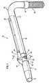
- FIG. 1is a perspective view of a wand according to a first embodiment to the instant invention
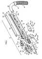
- FIG. 2is a exploded view of the wand of FIG. 1 ;
- FIG. 3is a cross-sectional view along the line 3 - 3 of FIG. 1 of the rotatable joint showing the lock in the locked position;
- FIG. 4is a cross-sectional view along the line 3 - 3 of FIG. 1 of the rotatable joint showing the lock in the unlocked position;
- FIG. 5is a cross-sectional view along the line 3 - 3 of FIG. 1 showing the upstream tube pivoted at an angle of about 90° to the downstream tube;
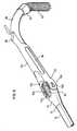
- FIG. 6is a perspective view of an alternate embodiment according to the instant invention.
- FIG. 7is a side view of the embodiment of FIG. 6 ;
- FIG. 8is an enlarged view of the rotatable joint of FIG. 7 showing the upstream tube bent at an angle of about 90° to the downstream tube;
- FIG. 9is a perspective view of a second alternate embodiment according to the instant invention.
- wand 10comprises upstream tube 12 , having upstream end 14 and downstream end 16 , and downstream tube 18 , having upstream end 20 and downstream end 22 .
- Upstream tube 12 and downstream tube 18are moveably connected together by means of a rotatable joint 24 .
- Upstream tube 12 and downstream tube 18are connected in fluid flow communication by a flexible fluid flow conduit 30 .
- a handle 26 for maneuvering wand 10is preferably provided.
- a lock release actuator 28is positioned adjacent handle 26 .
- Each of upstream and downstream tubes 12 and 18may be of any particular length and may be made of any rigid material (e.g. plastic or metal).
- Upstream end 14 of upstream tube 12may be a nozzle for cleaning a surface. Alternately, or in addition, it may be adapted to receive a surface cleaning tool, such as a surface cleaning head, additional extension tube, crevice cleaning tool or the like.
- Downstream end 22 of downstream tube 18may be connected directly with a cleaner body or may be connected thereto via a flexible hose 32 .
- Flexible hose 32may be any flexible hose or conduit known in the surface cleaning arts.
- flexible hose 32may be a plastic hose with a reinforcing member secured thereto in a spiral pattern.
- the upstream end 34 of flexible tube 32may have a handle 26 affixed thereto.
- handle 26comprises an intermediary component between downstream tube 18 and flexible hose 32 .
- flexible hose 32may be connected directly with downstream end 22 of tube 18 .
- handle 26may be incorporated as part of tube 18 , tube 18 may be used as the handle or the handle may be a separate component mounted thereto.
- Flexible fluid flow conduit 30(which is preferably a flexible hose) connects downstream end 26 of upstream tube 12 in fluid flow communication with upstream end 20 of downstream tube 18 . Accordingly, in operation, air is drawn into wand 10 via upstream end 14 and travels through upstream tube 12 (which define am upstream passage) through flexible fluid flow conduit 30 , through downstream tube 18 (which define am downstream passage) through flexible hose 32 to the cleaning unit of a surface cleaning apparatus. Additional intermediary members may be provided in the fluid flow path from the dirty fluid inlet (e.g., the inlet of a surface cleaning head) to the cleaning unit.
- the dirty fluid inlete.g., the inlet of a surface cleaning head
- the surface cleaning apparatusmay be any surface cleaning apparatus known in the art, such as an upright vacuum cleaner, canister vacuum cleaner, backpack vacuum cleaner, wet-dry vacuum cleaner or the like. If, for example, wand 10 is utilized with a canister or backpack vacuum cleaner, then it will be appreciated that wand 10 may be utilized as the extension tube that is steeringly connected to the surface cleaning head as is known in the art. Alternately, if the surface cleaning apparatus is an upright vacuum cleaner, then wand 10 may comprise an above floor cleaning wand. Accordingly, it will be appreciated that hose 32 may be secured to a surface cleaning apparatus by any means known in the art and wand 10 may optionally be removably mounted to the surface cleaning apparatus.
- Flexible fluid flow conduit 30may be secured to tubes 12 and 18 by any means known in the art.
- upstream end 36 of conduit 30may be secured to downstream end 16 of tube 12 by a flexible cuff provided on end 36 , which is slipped over end 16 .
- upstream end 36may be secured to tube 12 by an adhesive, an O-ring clamp, a friction fit or any other means known in the art.
- downstream end 38 of conduit 30may be secured to upstream end 20 of tube 18 .
- a collar or cuff 40may be provided on downstream end 16 of tube 12 and/or a collar or cuff 42 may be provided on upstream end 20 of tube 18 .
- collar 40may be used to secure upstream end 36 to tube 12 and collar 42 may be used to secure downstream end 38 to tube 18 .
- Collars 40 , 42may be separately molded elements which are affixed to tubes 12 , 18 by a friction fit, an adhesive, a set screw or the like.
- Conduit 30may be slipped over end 16 of tube 12 and collar 40 mounted thereover so as to secure conduit 30 to tube 12 .
- collar 40may have a mounting member for receiving upstream end 36 . Accordingly, collar 40 could include an airflow passage there through.
- collar 42may be used to secure downstream end 38 to tube 18 . It will be appreciated by those skilled in the art that various mounting means may be used and that this invention is not limited by the particular mounting means which is selected.
- rotatable joint 24comprises a first connector 44 which is associated with downstream end 16 of tube 12 and the second connector 46 associated with upstream end 20 of tube 18 .
- First and second connectors 44 , 46may be secured to tubes 12 and 18 by any means known in the art and may be moveably mounted with respect to each other by any means known in the art.
- first and second connectors 44 , 46are pivotably mounted together.
- tube 12is provided with a flange 48 having openings 50 .
- Flange 48may be secured to tube 12 by any means known in the art.
- flange 50may be secured to tube 12 by means of an adhesive, welding, screws or it may be formed integrally as part as tube 12 .
- Connector 44comprises first and second halves 52 , 54 , which may be secured together by screws 56 , rivets, an adhesive, welding or other means. Screw 56 passes through opening 58 in second half 54 , through opening 50 and is received in screw mount 60 , which is provided on the inner surface of first half 52 of first connector 44 . Accordingly, flange 48 is used to secure first connector 44 to tube 12 .
- first and second halves 52 , 54may be secured to tube 12 by any other means such as by an adhesive, welding, mechanical attachment or other means directly connecting first and second halves 52 , 54 directly to tube 12 .
- Second connector 46may be similarly mounted to tube 18 .
- tube 18may be provided with two flanges 62 each of which may be provided with one or more openings 64 .
- Second connector 46may accordingly comprise first and second halves 66 , 68 and be secured together by means of one or more screws 70 extending through opening 72 in second half 68 , through openings 64 in flanges 62 , into screw mount 74 provided on the inner surface of first half 66 .
- First and second connectors 44 , 46may be pivotally secured together by means of pivot screw 76 .
- each of first of second halves 52 , 54may have a recessed surface 78 having an opening 80 therein.
- First and second halves 66 , 68may also be provided with an opening 82 in mounting portion 84 thereof. Mounting portions 84 are spaced apart when first and second halves 66 , 68 are secured together on tube 18 .
- first and second connectors 44 , 46are secured to tubes 12 and 18 essentially as part of an exoskeleton, and provide the pivot mount for pivotally connecting tubes 12 and 18 together.
- first and second connectors 44 , 46may be of varying designs.
- wand 10includes a lock to secure wand 10 in at least one orientation.
- tubes 12 and 18extend linearly in accordance with a first mode or orientation such that the upstream and downstream flow passages provided therein extend essentially linearly (e.g. along the same longitudinal axis).
- a lockis provided to secure tubes 12 and 18 in this fixed orientation, which is particularly useful for moving a surface cleaning head over a floor to be cleaned. Any locking means known in the art may be used.
- first half 52is provided with a C-shaped flange 88 on inner surface 90 .
- a similar C-shaped flangemay be provided on the inner surface of second half 54 .
- the C-shaped flanges 88define a pocket 92 for receiving spring 94 .
- Lock member 96is moveably mounted in first connector 44 and is provided with extension 98 and locking portion 100 .
- lock member 96has an oblong internal opening 102 which seats on outer surface 104 of mount 106 . It will be appreciated that a mount 106 may be provided on the inner surface of recessed surface 78 of second half 54 .
- Extension 98is preferably tubular in shape and is seated within one end of spring 94 . Accordingly, spring 94 is positioned on extension 98 and then inserted into pocket 92 thereby securing spring 94 in position.
- a slot 108may be provided in the downstream side of first and second halves 52 .
- First and second halves 66 , 68have a pocket 112 for receiving locking portion 100 .
- Pocket 112may be formed, for example, by a C-shaped flange 110 provided on inner surface 116 of each of first and second halves 66 , 68 .
- first connector 44may rotate with respect to second connector 46 (see for example FIG. 5 ).
- Locking member 96may be moved between the locked position shown in FIG. 3 and the unlock position shown in FIG. 4 by any means known in the art, such as a lock release actuator.
- lock release actuator 28is positioned distal to rotatable joint 24 and, more preferably, adjacent to handle 26 .
- a linkage 116may be provided such that lock release actuator 28 may remotely actuate the lock.
- linkage 116has lock release actuator 28 provided at one end thereof and driving member 118 provided at an opposed end thereof. Actuator 28 and driving member 118 may be integrally formed as part of linkage 116 or may be separate elements.
- flanges 62may be spaced apart to define a channel within which linkage 116 is slideably mounted. Accordingly, when linkage 116 is moved in the direction of arrow A in FIGS. 4 and 5 , then driving member 118 will drive locking portion to the unlocked position shown in FIG. 4 . It will be appreciated that only one flange 62 may alternately be used and, for example, linkage 116 may have a channel in its tube side in which flange 62 is slideably received.
- linkage 116is biased to the locked position shown in FIG. 3 .
- a biasing membermay be provided to urge actuator 28 into the locked position.
- inner surface 114 of first and/or second half 66 , 68may be provided with an abutment member 120 .
- linkage 116may be provided with a spring mount or abutment member 122 .
- Spring 124may be positioned between abutment members 120 , 122 . Accordingly, when a user desires to rotate upstream tube 12 , the user may press actuator 28 moving linkage 116 in the direction of arrow A thereby compressing spring 124 and moving locking portion 100 into the unlocked position thereby permitting upstream tube 12 to rotate. When a user releases actuator 12 , spring 124 will drive linkage 116 into the locked position. Concurrently, spring 94 will move locking member into the locked position (i.e. driving locking portion 100 into pocket 112 ).
- a cap 126 or other covermay be provided for covering linkage 112 .
- Cap 126may be secured to tube 18 by any means known in the art and may be of any desired shape.
- cap 126is designed to seat on flanges 62 , such as by having members 128 removably receivable in openings 130 . Accordingly, cap 126 may be secured in place by positioning cap 126 over flanges 62 and pressing downwardly such that members 128 are received in openings 130 .
- cap 126may extend around all or a portion of tube 18 and may be secured thereto by any means known in the art, such as by means of an adhesive, welding, screws, clamps or the like.
- FIGS. 7 and 8exemplify an alternate embodiment. Having similar function are referred to using the same reference number in FIGS. 7 and 8 .
- first and second connectors 44 , 46are pivotably mounted together by pivot pin 132 .
- First and second connectorsare configured as collars which are provided on downstream end 16 of upstream tube 12 and on upstream end 20 of downstream tube 18 .
- Actuator 28comprises a trigger-like member which has an opening 134 for receiving a finger of a user.
- Locking member 96is pivotably mounted about pivot pin 136 and has a hook 138 provided at distal end 140 of locking member 96 . Hook 138 is removably received in recess 142 of first connector 44 .
- Arm 144has a first end 146 secured to linkage 116 and a second end 148 that is pivotably mounted to locking member 96 by pivot pin 150 .
- a channel 152is provided in tube 18 in which a portion of linkage 116 is seated so as to permit longitudinal movement in the direction of arrow A of FIG. 5 .
- a usermay use actuator 28 to move linkage 116 longitudinally along tube 18 in the direction of arrow B shown in FIG. 8 . Movement of linkage 116 in the downstream fluid flow direction causes arm 144 to apply a force to locking member 96 causing locking member 96 to pivot around pivot pin 116 thereby rotating hook 138 out of recess 142 . This permits tube 12 to rotate about pivot pin 132 relative to tube 18 .
- linkage 116may, for example, be a boden cable or any other member known in the art, which will provide a pulling force on locking member 96 .
- linkage 116may be secured to tube 18 by any means known in the art.
- locking member 96may engage first connector 44 by any other means known in the art.
- first connector 44is secured to downstream end 16 of tube 12 and is generally Y-shaped, having two opposed flanges 154 .
- second connector 46is secured to upstream end 20 of tube 18 and has a Y-shaped end having opposed flanges 156 which, when assembled, overlies flanges 154 .
- Each pair of flanges 154 , 156may be secured together by a pivot pin 158 .
- first and second connectors 44 , 46may be utilized for first and second connectors 44 , 46 .
- connectors 44 , 46may be formed as part of tubes 12 and 18 or may be separate members that are manufactured separately and then attached thereto. In any such case, connectors 44 , 46 are associated with tubes 12 and 18 and provide the movable joint. Accordingly, when connectors 44 , 46 move with respect to each other, tubes 12 and 18 move with respect to each other. It will be appreciated that movements other than pivotal may be utilized. For example, one member 44 , 46 may translate as well as rotate with respect to the other connector 44 , 46 .
- an actuatormay be provided adjacent the lock or distal thereto. If the actuator is provided distal to the lock, then it is preferably positioned proximate the handle. Preferably, the actuator is positioned such that a user may release the lock while holding the handle.
Landscapes
- Engineering & Computer Science (AREA)
- Mechanical Engineering (AREA)
- Electric Vacuum Cleaner (AREA)
- Cleaning In General (AREA)
Abstract
Description
- (a) an upstream rigid tube having an upstream end and a downstream end;
- (b) a downstream rigid tube releasably pivotally connected to the upstream rigid tube and having an upstream end and a downstream end; and,
- (c) a flexible fluid flow conduit connecting the upstream end of the downstream tube in fluid flow communication with the downstream end of the upstream tube.
- (a) an upstream rigid tube having a fluid flow passage having an upstream end and a downstream end;
- (b) a downstream rigid tube having a fluid flow passage having an upstream end and a downstream end;
- (c) the downstream rigid tube being moveably connected to the upstream rigid tube between a first position in which the upstream rigid tube is positioned in a fixed orientation with respect to the downstream rigid tube and a second position in which the upstream rigid tube is at an angle to the downstream rigid tube; and,
- (d) a flexible fluid flow conduit extending between the upstream end of the fluid flow passage of the downstream tube and the downstream end of the fluid flow passage of the upstream tube.
Claims (13)
Priority Applications (6)
| Application Number | Priority Date | Filing Date | Title |
|---|---|---|---|
| US12/010,358US8296901B2 (en) | 2008-01-24 | 2008-01-24 | Reconfigurable airflow wand |
| CNU2008202103708UCN201337395Y (en) | 2008-01-24 | 2008-10-24 | Air flow extension rod with reconfiguration performance |
| CNA2008101707029ACN101491423A (en) | 2008-01-24 | 2008-10-24 | Reconfigurable airflow wand |
| CA002647625ACA2647625A1 (en) | 2008-01-24 | 2008-12-19 | Reconfigurable airflow wand for a surface cleaning apparatus |
| EP09150898AEP2082675A3 (en) | 2008-01-24 | 2009-01-20 | Reconfigurable airflow wand |
| JP2009010651AJP2009172378A (en) | 2008-01-24 | 2009-01-21 | Airflow stick that can change shape |
Applications Claiming Priority (1)
| Application Number | Priority Date | Filing Date | Title |
|---|---|---|---|
| US12/010,358US8296901B2 (en) | 2008-01-24 | 2008-01-24 | Reconfigurable airflow wand |
Publications (2)
| Publication Number | Publication Date |
|---|---|
| US20090188997A1 US20090188997A1 (en) | 2009-07-30 |
| US8296901B2true US8296901B2 (en) | 2012-10-30 |
Family
ID=40482015
Family Applications (1)
| Application Number | Title | Priority Date | Filing Date |
|---|---|---|---|
| US12/010,358Active2031-07-06US8296901B2 (en) | 2008-01-24 | 2008-01-24 | Reconfigurable airflow wand |
Country Status (5)
| Country | Link |
|---|---|
| US (1) | US8296901B2 (en) |
| EP (1) | EP2082675A3 (en) |
| JP (1) | JP2009172378A (en) |
| CN (2) | CN101491423A (en) |
| CA (1) | CA2647625A1 (en) |
Cited By (9)
| Publication number | Priority date | Publication date | Assignee | Title |
|---|---|---|---|---|
| USD681894S1 (en)* | 2012-01-12 | 2013-05-07 | Telebrands Corp. | Vacuum adapter for lint removal |
| US20170112343A1 (en)* | 2015-10-22 | 2017-04-27 | Sharkninja Operating Llc | Vacuum cleaning device with foldable wand to provide storage configuration |
| US11058267B2 (en) | 2016-04-27 | 2021-07-13 | Aktiebolaget Electrolux | Vacuum cleaner and vacuum cleaner system |
| US20220031131A1 (en)* | 2020-07-29 | 2022-02-03 | Sharkninja Operating Llc | Surface cleaning apparatus |
| US11534042B2 (en) | 2017-12-15 | 2022-12-27 | Aktiebolaget Electrolux | Vacuum cleaner |
| US20230375109A1 (en)* | 2022-05-19 | 2023-11-23 | Beijing Xiaomi Mobile Software Co., Ltd. | Bendable joint, cleaner connecting pipe, and cleaner |
| US11937762B2 (en) | 2019-06-26 | 2024-03-26 | Milwaukee Electric Tool Corporation | Vacuum tools |
| US12053141B2 (en) | 2021-06-18 | 2024-08-06 | Sharkninja Operating Llc | Vacuum cleaning device with foldable wand to provide storage configuration |
| USD1041104S1 (en)* | 2021-06-18 | 2024-09-03 | Sharkninja Operating Llc | Vacuum cleaner |
Families Citing this family (18)
| Publication number | Priority date | Publication date | Assignee | Title |
|---|---|---|---|---|
| CN102727139B (en)* | 2011-04-14 | 2014-12-17 | 科沃斯机器人有限公司 | Telescopic tube for dust collector |
| US9955831B2 (en) | 2012-03-09 | 2018-05-01 | Sharkninja Operating Llc | Surface cleaning apparatus with an adjustable handle |
| CN104013359A (en)* | 2014-05-09 | 2014-09-03 | 苏州艾利欧电器有限公司 | Joint brush |
| CN105877611B (en)* | 2016-02-26 | 2017-11-21 | 苏州爱建电器有限公司 | The steering knuckle and hand held cleaner of dust catcher |
| CN105581730B (en) | 2016-02-26 | 2017-11-21 | 苏州爱建电器有限公司 | The steering knuckle and hand held cleaner of hand held cleaner |
| GB2552183B (en)* | 2016-07-13 | 2018-12-05 | Dyson Technology Ltd | A tool for a vacuum cleaner |
| GB2552184B (en)* | 2016-07-13 | 2018-12-05 | Dyson Technology Ltd | A tool for a vacuum cleaner |
| GB2552185B (en)* | 2016-07-13 | 2018-12-05 | Dyson Technology Ltd | A tool for a vacuum cleaner |
| USD860562S1 (en) | 2017-09-19 | 2019-09-17 | Kärcher North America, Inc. | Vacuum wand |
| US11051668B2 (en)* | 2018-05-25 | 2021-07-06 | Sharkninja Operating Llc | Vacuum cleaner having reconfigurable weight distribution |
| FR3088819B1 (en) | 2018-11-22 | 2021-01-08 | Seb Sa | Vacuum duct for stick vacuum cleaner equipped with an electric wire |
| KR200489333Y1 (en)* | 2018-12-26 | 2019-06-03 | 박봉재 | A suction pipe of suction cleaner comprising |
| CN109832999A (en)* | 2019-03-29 | 2019-06-04 | 天佑电器(苏州)有限公司 | Burnisher |
| KR102267512B1 (en)* | 2019-12-03 | 2021-06-18 | 엘지전자 주식회사 | Vacuum cleaner |
| USD1089916S1 (en)* | 2021-06-04 | 2025-08-19 | Sharkninja Operating Llc | Vacuum wand |
| USD1021302S1 (en)* | 2022-02-28 | 2024-04-02 | William Matthew Walker | Carwash vacuum detailing attachment |
| FR3141052B1 (en)* | 2022-10-21 | 2024-10-25 | Seb Sa | Vacuum cleaner duct equipped with an articulation device |
| FR3151476B1 (en)* | 2023-07-26 | 2025-07-11 | Seb Sa | Vacuum duct equipped with an articulation device |
Citations (42)
| Publication number | Priority date | Publication date | Assignee | Title |
|---|---|---|---|---|
| GB613995A (en) | 1940-10-05 | 1948-12-08 | Fisker & Nielsen As | Improvements in and relating to nozzles for vacuum cleaners |
| DE3913419A1 (en) | 1989-04-24 | 1990-10-25 | Vorwerk Co Interholding | Fixing unit for air supply joint for vacuum cleaner - forms air path by rigid tube and freely-moving torsionally stiff connection between two tubular parts |
| US5472346A (en) | 1993-04-23 | 1995-12-05 | Electrolux Corporation | Swivel joint for vacuum cleaner |
| AU671764B2 (en) | 1993-09-07 | 1996-09-05 | Palm Plumbing Works Pty Ltd | Friction joint assembly |
| US5927758A (en) | 1997-04-07 | 1999-07-27 | Aktiebolaget Electrolux | Pivotable vacuum cleaner tube shaft |
| US5996175A (en) | 1998-07-23 | 1999-12-07 | Fusco; Edward | Adjustable vacuum handle construction |
| US6032321A (en) | 1998-06-16 | 2000-03-07 | Shirey; William | Washing tool |
| WO2000065978A1 (en) | 1999-04-30 | 2000-11-09 | Bystroem Johan | A joint device |
| US6209925B1 (en) | 1998-03-12 | 2001-04-03 | Aktiebolaget Electrolux | Turn shaft for a vacuum cleaner |
| US6301740B1 (en) | 2000-02-18 | 2001-10-16 | Humberto M. Quiroz | Disposable brush |
| US6317920B1 (en) | 1998-11-30 | 2001-11-20 | Royal Appliance Mfg. Co. | Vacuum cleaner with above-floor cleaning tool |
| US6345408B1 (en) | 1998-07-28 | 2002-02-12 | Sharp Kabushiki Kaisha | Electric vacuum cleaner and nozzle unit therefor |
| US6382058B1 (en) | 1999-06-15 | 2002-05-07 | Greg J. Owoc | Multi-jointed wrench handle |
| US20020078519A1 (en) | 2000-12-27 | 2002-06-27 | Michael Boothby | Low profile combination scrubbing and squeegee device |
| US20020101075A1 (en) | 2001-01-29 | 2002-08-01 | Park Deog Bae | Extension tube in vacuum cleaner |
| US6553613B2 (en) | 2000-03-23 | 2003-04-29 | Sharp Kabushiki Kaisha | Electric vacuum cleaner |
| US6561549B1 (en) | 1998-09-10 | 2003-05-13 | Mdc Sarl | Sealing connector with variable geometry |
| US6581974B1 (en) | 2001-09-29 | 2003-06-24 | Ragner Manufacturing, Llc | Pivot adaptor attachment for vacuum cleaners |
| US20030167595A1 (en) | 2002-03-05 | 2003-09-11 | Samsung Gwangju Electronics Co., Ltd. | Joint assembly of vacuum cleaner and vacuum cleaner having the same |
| US20040007278A1 (en) | 2002-06-06 | 2004-01-15 | Williams Robert M. | Flexible conduit and method for forming the same |
| US6768073B1 (en) | 2003-07-03 | 2004-07-27 | The Hoover Company | Pivoting handle and control arrangement for a floor care appliance |
| US20040163202A1 (en) | 2003-02-26 | 2004-08-26 | Sanyo Electric Co., Ltd. | Electric vacuum cleaner |
| US20040211029A1 (en) | 2001-05-31 | 2004-10-28 | Kaoru Ueda | Tube shaft for a vacuum cleaner |
| US20040244131A1 (en) | 2003-06-05 | 2004-12-09 | Cassar Simon Ralph | Quick disconnect swivel connector for multiple cleaning devices |
| WO2005034706A2 (en) | 2003-10-09 | 2005-04-21 | T.P.A. Impex S.P.A. | Sucking device |
| US20050081326A1 (en) | 2003-10-20 | 2005-04-21 | Samsung Gwangju Electronics Co., Ltd. | Bendable extension pipe having joint for vacuum cleaner |
| US20050115017A1 (en) | 2003-12-02 | 2005-06-02 | Jung-Hoon Kim | Extension pipe having a joint for vacuum cleaner |
| US20050115018A1 (en) | 2003-12-02 | 2005-06-02 | Jeon Kyong-Hui | Bendable extension pipe for vacuum cleaner |
| US20050125945A1 (en) | 2003-12-15 | 2005-06-16 | Samsung Gwangju Electronics Co., Ltd. | Extension pipe having a joint for vacuum cleaner |
| US20050125944A1 (en) | 2003-12-11 | 2005-06-16 | Lg Electronics Inc. | Upright type vacuum cleaner |
| US7000288B2 (en) | 2000-01-13 | 2006-02-21 | Dyson Limited | Hose and wand assembly |
| US7055204B2 (en) | 2003-03-11 | 2006-06-06 | The Evercare Company | Cleaning device |
| US20060156510A1 (en) | 2005-01-14 | 2006-07-20 | Samsung Gwangiu Electronics Co., Ltd | Articulative extension pipe of vacuum cleaner |
| US20060156509A1 (en) | 2005-01-18 | 2006-07-20 | Luebbering Gregory W | Vacuum cleaner with collapsible handle |
| US20060242775A1 (en) | 2005-04-29 | 2006-11-02 | Kwonnie Electrical Products Limited | Electric cleaning sweeper |
| US7162796B2 (en) | 1998-04-10 | 2007-01-16 | Micron Technology, Inc. | Method of making an interposer with contact structures |
| US7168128B2 (en) | 2001-03-08 | 2007-01-30 | Dyson Technology Limited | Wand assembly for a domestic appliance |
| EP1764021A1 (en) | 2005-09-16 | 2007-03-21 | IMETEC S.p.A. | Extension tube for domestic cleaning devices and domestic cleaning device comprising such an extension tube |
| US7219390B2 (en) | 2003-12-10 | 2007-05-22 | Bissell Homecare, Inc. | Surface cleaner with folding upright handle and method of packaging same |
| WO2007086798A1 (en) | 2006-01-29 | 2007-08-02 | Lennart Olsson | Vacuum cleaner device |
| US20070174994A1 (en) | 2003-05-29 | 2007-08-02 | Dyson Technology Limited | Cleaning head |
| US7496984B2 (en) | 2006-12-29 | 2009-03-03 | Kwonnie Electrical Products Limited | Floor cleaning apparatus with elongate handle and handle extension |
Family Cites Families (2)
| Publication number | Priority date | Publication date | Assignee | Title |
|---|---|---|---|---|
| US5772346A (en)* | 1997-04-22 | 1998-06-30 | Medi-Flex Hospital Products, Inc. | Liquid applicator with structural insert |
| US5996185A (en)* | 1998-02-20 | 1999-12-07 | Luntz; S. Richard | Writing instrument |
- 2008
- 2008-01-24USUS12/010,358patent/US8296901B2/enactiveActive
- 2008-10-24CNCNA2008101707029Apatent/CN101491423A/enactivePending
- 2008-10-24CNCNU2008202103708Upatent/CN201337395Y/ennot_activeExpired - Fee Related
- 2008-12-19CACA002647625Apatent/CA2647625A1/ennot_activeAbandoned
- 2009
- 2009-01-20EPEP09150898Apatent/EP2082675A3/ennot_activeWithdrawn
- 2009-01-21JPJP2009010651Apatent/JP2009172378A/enactivePending
Patent Citations (47)
| Publication number | Priority date | Publication date | Assignee | Title |
|---|---|---|---|---|
| GB613995A (en) | 1940-10-05 | 1948-12-08 | Fisker & Nielsen As | Improvements in and relating to nozzles for vacuum cleaners |
| DE3913419A1 (en) | 1989-04-24 | 1990-10-25 | Vorwerk Co Interholding | Fixing unit for air supply joint for vacuum cleaner - forms air path by rigid tube and freely-moving torsionally stiff connection between two tubular parts |
| US5472346A (en) | 1993-04-23 | 1995-12-05 | Electrolux Corporation | Swivel joint for vacuum cleaner |
| AU671764B2 (en) | 1993-09-07 | 1996-09-05 | Palm Plumbing Works Pty Ltd | Friction joint assembly |
| US5927758A (en) | 1997-04-07 | 1999-07-27 | Aktiebolaget Electrolux | Pivotable vacuum cleaner tube shaft |
| US6209925B1 (en) | 1998-03-12 | 2001-04-03 | Aktiebolaget Electrolux | Turn shaft for a vacuum cleaner |
| US7162796B2 (en) | 1998-04-10 | 2007-01-16 | Micron Technology, Inc. | Method of making an interposer with contact structures |
| US6032321A (en) | 1998-06-16 | 2000-03-07 | Shirey; William | Washing tool |
| US5996175A (en) | 1998-07-23 | 1999-12-07 | Fusco; Edward | Adjustable vacuum handle construction |
| US6345408B1 (en) | 1998-07-28 | 2002-02-12 | Sharp Kabushiki Kaisha | Electric vacuum cleaner and nozzle unit therefor |
| US20030163891A1 (en) | 1998-07-28 | 2003-09-04 | Sharp Kabushiki Kaisha | Electric vacuum cleaner and nozzle unit therefor |
| US6561549B1 (en) | 1998-09-10 | 2003-05-13 | Mdc Sarl | Sealing connector with variable geometry |
| US6317920B1 (en) | 1998-11-30 | 2001-11-20 | Royal Appliance Mfg. Co. | Vacuum cleaner with above-floor cleaning tool |
| WO2000065978A1 (en) | 1999-04-30 | 2000-11-09 | Bystroem Johan | A joint device |
| US6382058B1 (en) | 1999-06-15 | 2002-05-07 | Greg J. Owoc | Multi-jointed wrench handle |
| US7000288B2 (en) | 2000-01-13 | 2006-02-21 | Dyson Limited | Hose and wand assembly |
| US6301740B1 (en) | 2000-02-18 | 2001-10-16 | Humberto M. Quiroz | Disposable brush |
| US6553613B2 (en) | 2000-03-23 | 2003-04-29 | Sharp Kabushiki Kaisha | Electric vacuum cleaner |
| US20020078519A1 (en) | 2000-12-27 | 2002-06-27 | Michael Boothby | Low profile combination scrubbing and squeegee device |
| US20020101075A1 (en) | 2001-01-29 | 2002-08-01 | Park Deog Bae | Extension tube in vacuum cleaner |
| US6695352B2 (en) | 2001-01-29 | 2004-02-24 | Lg Electronics Inc. | Extension tube in vacuum cleaner |
| EP1226777B1 (en) | 2001-01-29 | 2005-03-30 | Lg Electronics Inc. | Extension tube assembly for a vacuum cleaner |
| US7168128B2 (en) | 2001-03-08 | 2007-01-30 | Dyson Technology Limited | Wand assembly for a domestic appliance |
| US20040211029A1 (en) | 2001-05-31 | 2004-10-28 | Kaoru Ueda | Tube shaft for a vacuum cleaner |
| US6581974B1 (en) | 2001-09-29 | 2003-06-24 | Ragner Manufacturing, Llc | Pivot adaptor attachment for vacuum cleaners |
| US20030167595A1 (en) | 2002-03-05 | 2003-09-11 | Samsung Gwangju Electronics Co., Ltd. | Joint assembly of vacuum cleaner and vacuum cleaner having the same |
| US6904640B2 (en) | 2002-03-05 | 2005-06-14 | Samsung Gwangju Electronics Co. | Joint assembly of vacuum cleaner and vacuum cleaner having the same |
| US20040007278A1 (en) | 2002-06-06 | 2004-01-15 | Williams Robert M. | Flexible conduit and method for forming the same |
| US20040163202A1 (en) | 2003-02-26 | 2004-08-26 | Sanyo Electric Co., Ltd. | Electric vacuum cleaner |
| US7350263B2 (en) | 2003-02-26 | 2008-04-01 | Sanyo Electric Co., Ltd | Electric vacuum cleaner |
| US7055204B2 (en) | 2003-03-11 | 2006-06-06 | The Evercare Company | Cleaning device |
| US20070174994A1 (en) | 2003-05-29 | 2007-08-02 | Dyson Technology Limited | Cleaning head |
| US20040244131A1 (en) | 2003-06-05 | 2004-12-09 | Cassar Simon Ralph | Quick disconnect swivel connector for multiple cleaning devices |
| US6768073B1 (en) | 2003-07-03 | 2004-07-27 | The Hoover Company | Pivoting handle and control arrangement for a floor care appliance |
| WO2005034706A2 (en) | 2003-10-09 | 2005-04-21 | T.P.A. Impex S.P.A. | Sucking device |
| US20050081326A1 (en) | 2003-10-20 | 2005-04-21 | Samsung Gwangju Electronics Co., Ltd. | Bendable extension pipe having joint for vacuum cleaner |
| US20050115018A1 (en) | 2003-12-02 | 2005-06-02 | Jeon Kyong-Hui | Bendable extension pipe for vacuum cleaner |
| US20050115017A1 (en) | 2003-12-02 | 2005-06-02 | Jung-Hoon Kim | Extension pipe having a joint for vacuum cleaner |
| US7219390B2 (en) | 2003-12-10 | 2007-05-22 | Bissell Homecare, Inc. | Surface cleaner with folding upright handle and method of packaging same |
| US20050125944A1 (en) | 2003-12-11 | 2005-06-16 | Lg Electronics Inc. | Upright type vacuum cleaner |
| US20050125945A1 (en) | 2003-12-15 | 2005-06-16 | Samsung Gwangju Electronics Co., Ltd. | Extension pipe having a joint for vacuum cleaner |
| US20060156510A1 (en) | 2005-01-14 | 2006-07-20 | Samsung Gwangiu Electronics Co., Ltd | Articulative extension pipe of vacuum cleaner |
| US20060156509A1 (en) | 2005-01-18 | 2006-07-20 | Luebbering Gregory W | Vacuum cleaner with collapsible handle |
| US20060242775A1 (en) | 2005-04-29 | 2006-11-02 | Kwonnie Electrical Products Limited | Electric cleaning sweeper |
| EP1764021A1 (en) | 2005-09-16 | 2007-03-21 | IMETEC S.p.A. | Extension tube for domestic cleaning devices and domestic cleaning device comprising such an extension tube |
| WO2007086798A1 (en) | 2006-01-29 | 2007-08-02 | Lennart Olsson | Vacuum cleaner device |
| US7496984B2 (en) | 2006-12-29 | 2009-03-03 | Kwonnie Electrical Products Limited | Floor cleaning apparatus with elongate handle and handle extension |
Non-Patent Citations (1)
| Title |
|---|
| European Search Report of EP 09 15 0898 mailed May 20, 2010. |
Cited By (14)
| Publication number | Priority date | Publication date | Assignee | Title |
|---|---|---|---|---|
| USD681894S1 (en)* | 2012-01-12 | 2013-05-07 | Telebrands Corp. | Vacuum adapter for lint removal |
| US11896184B2 (en) | 2015-10-22 | 2024-02-13 | Sharkninja Operating Llc | Vacuum cleaning device with foldable wand to provide storage configuration |
| US20170112343A1 (en)* | 2015-10-22 | 2017-04-27 | Sharkninja Operating Llc | Vacuum cleaning device with foldable wand to provide storage configuration |
| WO2018080873A1 (en) | 2015-10-22 | 2018-05-03 | Sharkninja Operating Llc | Vacuum cleaning device with foldable wand to provide storage configuration |
| DE212017000236U1 (en) | 2015-10-22 | 2019-05-24 | Sharkninja Operating Llc | A vacuum cleaner, and more particularly a vacuum cleaner with a foldable tube to provide a storage configuration |
| EP3566628A1 (en) | 2015-10-22 | 2019-11-13 | SharkNinja Operating LLC | Vacuum cleaning device with foldable wand to provide storage configuration |
| US10966581B2 (en)* | 2015-10-22 | 2021-04-06 | Sharkninja Operating Llc | Vacuum cleaning device with foldable wand to provide storage configuration |
| US11058267B2 (en) | 2016-04-27 | 2021-07-13 | Aktiebolaget Electrolux | Vacuum cleaner and vacuum cleaner system |
| US11534042B2 (en) | 2017-12-15 | 2022-12-27 | Aktiebolaget Electrolux | Vacuum cleaner |
| US11937762B2 (en) | 2019-06-26 | 2024-03-26 | Milwaukee Electric Tool Corporation | Vacuum tools |
| US20220031131A1 (en)* | 2020-07-29 | 2022-02-03 | Sharkninja Operating Llc | Surface cleaning apparatus |
| US12053141B2 (en) | 2021-06-18 | 2024-08-06 | Sharkninja Operating Llc | Vacuum cleaning device with foldable wand to provide storage configuration |
| USD1041104S1 (en)* | 2021-06-18 | 2024-09-03 | Sharkninja Operating Llc | Vacuum cleaner |
| US20230375109A1 (en)* | 2022-05-19 | 2023-11-23 | Beijing Xiaomi Mobile Software Co., Ltd. | Bendable joint, cleaner connecting pipe, and cleaner |
Also Published As
| Publication number | Publication date |
|---|---|
| US20090188997A1 (en) | 2009-07-30 |
| JP2009172378A (en) | 2009-08-06 |
| CN101491423A (en) | 2009-07-29 |
| CN201337395Y (en) | 2009-11-04 |
| EP2082675A3 (en) | 2010-06-23 |
| EP2082675A2 (en) | 2009-07-29 |
| CA2647625A1 (en) | 2009-07-24 |
Similar Documents
| Publication | Publication Date | Title |
|---|---|---|
| US8296901B2 (en) | Reconfigurable airflow wand | |
| US10327609B2 (en) | Surface cleaning apparatus | |
| US8713754B2 (en) | Surface cleaning apparatus | |
| US8186007B2 (en) | Upright vacuum cleaner | |
| US8181309B2 (en) | Upright vacuum cleaner | |
| US8272097B2 (en) | Upright vacuum cleaner | |
| US9138114B2 (en) | Surface cleaning apparatus | |
| EP1265519B1 (en) | Hose and wand assembly | |
| US8448295B2 (en) | Vacuum cleaner with rotating handle | |
| US6055703A (en) | Upright vacuum cleaner having improved steering apparatus with a lock out feature | |
| US8667643B2 (en) | Method and apparatus for assisting pivot motion of a handle in a floor treatment device | |
| CN201070328Y (en) | floor cleaning device | |
| CN106998972B (en) | Surface cleaning device with a handle that pivots sideways | |
| US20040194247A1 (en) | Vacuum cleaner | |
| US8201302B2 (en) | Upright vacuum cleaner | |
| CN1947638B (en) | vacuum cleaner | |
| US20110219569A1 (en) | Vacuum Cleaner with Movable Wheel | |
| CA2678119A1 (en) | Surface cleaning apparatus | |
| US8407853B1 (en) | High place vacuum cleaner attachment | |
| CN202437016U (en) | Connecting rod for dust collector | |
| GB2462124A (en) | Changeover valve cable actuating mechanism | |
| EP3030130B1 (en) | Separable hose system for steam and vacuum cleaning | |
| JP2000005107A5 (en) | ||
| GB2413063A (en) | Vacuum cleaner having suction handle |
Legal Events
| Date | Code | Title | Description |
|---|---|---|---|
| AS | Assignment | Owner name:EURO-PRO OPERATING LLC, MASSACHUSETTS Free format text:ASSIGNMENT OF ASSIGNORS INTEREST;ASSIGNOR:PRODUCT INSIGHT, INC.;REEL/FRAME:021153/0263 Effective date:20080611 Owner name:PRODUCT INSIGHT, INC., MASSACHUSETTS Free format text:ASSIGNMENT OF ASSIGNORS INTEREST;ASSIGNORS:VARNEY, JAMES R.;HOTALING, BRYAN R.;MACNEILL, JOHN A.;REEL/FRAME:021134/0299 Effective date:20080611 Owner name:EURO-PRO OPERATING LLC, MASSACHUSETTS Free format text:ASSIGNMENT OF ASSIGNORS INTEREST;ASSIGNORS:ROSENZWEIG, MARK;OFFIR, YIGAL;REEL/FRAME:021134/0296 Effective date:20080611 | |
| AS | Assignment | Owner name:BANK OF AMERICA, N.A.,MASSACHUSETTS Free format text:SECURITY AGREEMENT;ASSIGNOR:EURO-PRO OPERATING LLC;REEL/FRAME:024630/0058 Effective date:20100628 Owner name:BANK OF AMERICA, N.A., MASSACHUSETTS Free format text:SECURITY AGREEMENT;ASSIGNOR:EURO-PRO OPERATING LLC;REEL/FRAME:024630/0058 Effective date:20100628 | |
| STCF | Information on status: patent grant | Free format text:PATENTED CASE | |
| FEPP | Fee payment procedure | Free format text:PAT HOLDER NO LONGER CLAIMS SMALL ENTITY STATUS, ENTITY STATUS SET TO UNDISCOUNTED (ORIGINAL EVENT CODE: STOL); ENTITY STATUS OF PATENT OWNER: LARGE ENTITY | |
| AS | Assignment | Owner name:SHARKNINJA OPERATING LLC, MASSACHUSETTS Free format text:CHANGE OF NAME;ASSIGNOR:EURO-PRO OPERATING LLC;REEL/FRAME:036333/0287 Effective date:20150713 | |
| FPAY | Fee payment | Year of fee payment:4 | |
| AS | Assignment | Owner name:SHARKNINJA OPERATING LLC, MASSACHUSETTS Free format text:RELEASE BY SECURED PARTY;ASSIGNOR:BANK OF AMERICA, N.A.;REEL/FRAME:044207/0652 Effective date:20170929 | |
| MAFP | Maintenance fee payment | Free format text:PAYMENT OF MAINTENANCE FEE, 8TH YEAR, LARGE ENTITY (ORIGINAL EVENT CODE: M1552); ENTITY STATUS OF PATENT OWNER: LARGE ENTITY Year of fee payment:8 | |
| AS | Assignment | Owner name:BANK OF AMERICA, N.A., AS ADMINISTRATIVE AGENT, TEXAS Free format text:NOTICE OF GRANT OF SECURITY INTEREST IN PATENTS;ASSIGNOR:SHARKNINJA OPERATING LLC;REEL/FRAME:064600/0098 Effective date:20230720 | |
| MAFP | Maintenance fee payment | Free format text:PAYMENT OF MAINTENANCE FEE, 12TH YEAR, LARGE ENTITY (ORIGINAL EVENT CODE: M1553); ENTITY STATUS OF PATENT OWNER: LARGE ENTITY Year of fee payment:12 |