US8296817B2 - Apparatus for transporting home networking frame-based communications signals over coaxial cables - Google Patents
Apparatus for transporting home networking frame-based communications signals over coaxial cablesDownload PDFInfo
- Publication number
- US8296817B2 US8296817B2US10/150,187US15018702AUS8296817B2US 8296817 B2US8296817 B2US 8296817B2US 15018702 AUS15018702 AUS 15018702AUS 8296817 B2US8296817 B2US 8296817B2
- Authority
- US
- United States
- Prior art keywords
- port
- coaxial cable
- coaxial
- adapter
- hpna
- Prior art date
- Legal status (The legal status is an assumption and is not a legal conclusion. Google has not performed a legal analysis and makes no representation as to the accuracy of the status listed.)
- Expired - Fee Related, expires
Links
- 230000006855networkingEffects0.000titleclaimsabstractdescription23
- 238000004891communicationMethods0.000titleclaimsabstractdescription22
- 230000001902propagating effectEffects0.000claimsabstractdescription14
- 238000000034methodMethods0.000claimsabstractdescription10
- 239000003990capacitorSubstances0.000claimsdescription8
- 239000011324beadSubstances0.000claimsdescription4
- 229910000859α-FeInorganic materials0.000claimsdescription4
- 230000008878couplingEffects0.000abstractdescription2
- 238000010168coupling processMethods0.000abstractdescription2
- 238000005859coupling reactionMethods0.000abstractdescription2
- 238000002955isolationMethods0.000description11
- 238000010586diagramMethods0.000description5
- 238000009434installationMethods0.000description5
- 230000005540biological transmissionEffects0.000description4
- 238000001152differential interference contrast microscopyMethods0.000description4
- 238000005516engineering processMethods0.000description3
- 230000000116mitigating effectEffects0.000description2
- 238000001228spectrumMethods0.000description2
- JICJBGPOMZQUBB-UHFFFAOYSA-N7-[(3-chloro-6-methyl-5,5-dioxido-6,11-dihydrodibenzo[c,f][1,2]thiazepin-11-yl)amino]heptanoic acidChemical compoundO=S1(=O)N(C)C2=CC=CC=C2C(NCCCCCCC(O)=O)C2=CC=C(Cl)C=C21JICJBGPOMZQUBB-UHFFFAOYSA-N0.000description1
- RYGMFSIKBFXOCR-UHFFFAOYSA-NCopperChemical compound[Cu]RYGMFSIKBFXOCR-UHFFFAOYSA-N0.000description1
- 235000014676Phragmites communisNutrition0.000description1
- 230000003466anti-cipated effectEffects0.000description1
- 230000000903blocking effectEffects0.000description1
- 230000003203everyday effectEffects0.000description1
- 230000002452interceptive effectEffects0.000description1
- 238000007726management methodMethods0.000description1
- 238000005457optimizationMethods0.000description1
- 238000009738saturatingMethods0.000description1
- 230000003595spectral effectEffects0.000description1
- 229960005138tianeptineDrugs0.000description1
- 238000004804windingMethods0.000description1
Images


Classifications
- H—ELECTRICITY
- H04—ELECTRIC COMMUNICATION TECHNIQUE
- H04L—TRANSMISSION OF DIGITAL INFORMATION, e.g. TELEGRAPHIC COMMUNICATION
- H04L12/00—Data switching networks
- H04L12/28—Data switching networks characterised by path configuration, e.g. LAN [Local Area Networks] or WAN [Wide Area Networks]
- H04L12/2803—Home automation networks
- H04L12/2838—Distribution of signals within a home automation network, e.g. involving splitting/multiplexing signals to/from different paths
- H—ELECTRICITY
- H03—ELECTRONIC CIRCUITRY
- H03H—IMPEDANCE NETWORKS, e.g. RESONANT CIRCUITS; RESONATORS
- H03H7/00—Multiple-port networks comprising only passive electrical elements as network components
- H03H7/46—Networks for connecting several sources or loads, working on different frequencies or frequency bands, to a common load or source
- H—ELECTRICITY
- H04—ELECTRIC COMMUNICATION TECHNIQUE
- H04L—TRANSMISSION OF DIGITAL INFORMATION, e.g. TELEGRAPHIC COMMUNICATION
- H04L12/00—Data switching networks
- H04L12/28—Data switching networks characterised by path configuration, e.g. LAN [Local Area Networks] or WAN [Wide Area Networks]
- H04L12/2803—Home automation networks
- H—ELECTRICITY
- H04—ELECTRIC COMMUNICATION TECHNIQUE
- H04M—TELEPHONIC COMMUNICATION
- H04M1/00—Substation equipment, e.g. for use by subscribers
- H04M1/71—Substation extension arrangements
- H04M1/715—Substation extension arrangements using two or more extensions per line
- H—ELECTRICITY
- H04—ELECTRIC COMMUNICATION TECHNIQUE
- H04N—PICTORIAL COMMUNICATION, e.g. TELEVISION
- H04N21/00—Selective content distribution, e.g. interactive television or video on demand [VOD]
- H04N21/40—Client devices specifically adapted for the reception of or interaction with content, e.g. set-top-box [STB]; Operations thereof
- H04N21/41—Structure of client; Structure of client peripherals
- H04N21/426—Internal components of the client ; Characteristics thereof
- H04N21/42676—Internal components of the client ; Characteristics thereof for modulating an analogue carrier signal to encode digital information or demodulating it to decode digital information, e.g. ADSL or cable modem
- H—ELECTRICITY
- H04—ELECTRIC COMMUNICATION TECHNIQUE
- H04N—PICTORIAL COMMUNICATION, e.g. TELEVISION
- H04N21/00—Selective content distribution, e.g. interactive television or video on demand [VOD]
- H04N21/40—Client devices specifically adapted for the reception of or interaction with content, e.g. set-top-box [STB]; Operations thereof
- H04N21/43—Processing of content or additional data, e.g. demultiplexing additional data from a digital video stream; Elementary client operations, e.g. monitoring of home network or synchronising decoder's clock; Client middleware
- H04N21/436—Interfacing a local distribution network, e.g. communicating with another STB or one or more peripheral devices inside the home
- H04N21/43615—Interfacing a Home Network, e.g. for connecting the client to a plurality of peripherals
- H—ELECTRICITY
- H04—ELECTRIC COMMUNICATION TECHNIQUE
- H04N—PICTORIAL COMMUNICATION, e.g. TELEVISION
- H04N21/00—Selective content distribution, e.g. interactive television or video on demand [VOD]
- H04N21/40—Client devices specifically adapted for the reception of or interaction with content, e.g. set-top-box [STB]; Operations thereof
- H04N21/47—End-user applications
- H04N21/478—Supplemental services, e.g. displaying phone caller identification, shopping application
- H04N21/4782—Web browsing, e.g. WebTV
- H—ELECTRICITY
- H04—ELECTRIC COMMUNICATION TECHNIQUE
- H04N—PICTORIAL COMMUNICATION, e.g. TELEVISION
- H04N21/00—Selective content distribution, e.g. interactive television or video on demand [VOD]
- H04N21/40—Client devices specifically adapted for the reception of or interaction with content, e.g. set-top-box [STB]; Operations thereof
- H04N21/47—End-user applications
- H04N21/478—Supplemental services, e.g. displaying phone caller identification, shopping application
- H04N21/4788—Supplemental services, e.g. displaying phone caller identification, shopping application communicating with other users, e.g. chatting
- H—ELECTRICITY
- H04—ELECTRIC COMMUNICATION TECHNIQUE
- H04N—PICTORIAL COMMUNICATION, e.g. TELEVISION
- H04N21/00—Selective content distribution, e.g. interactive television or video on demand [VOD]
- H04N21/60—Network structure or processes for video distribution between server and client or between remote clients; Control signalling between clients, server and network components; Transmission of management data between server and client, e.g. sending from server to client commands for recording incoming content stream; Communication details between server and client
- H04N21/61—Network physical structure; Signal processing
- H04N21/6106—Network physical structure; Signal processing specially adapted to the downstream path of the transmission network
- H04N21/6118—Network physical structure; Signal processing specially adapted to the downstream path of the transmission network involving cable transmission, e.g. using a cable modem
- H—ELECTRICITY
- H04—ELECTRIC COMMUNICATION TECHNIQUE
- H04N—PICTORIAL COMMUNICATION, e.g. TELEVISION
- H04N21/00—Selective content distribution, e.g. interactive television or video on demand [VOD]
- H04N21/60—Network structure or processes for video distribution between server and client or between remote clients; Control signalling between clients, server and network components; Transmission of management data between server and client, e.g. sending from server to client commands for recording incoming content stream; Communication details between server and client
- H04N21/61—Network physical structure; Signal processing
- H04N21/6106—Network physical structure; Signal processing specially adapted to the downstream path of the transmission network
- H04N21/6137—Network physical structure; Signal processing specially adapted to the downstream path of the transmission network involving transmission via a telephone network, e.g. POTS
- H—ELECTRICITY
- H04—ELECTRIC COMMUNICATION TECHNIQUE
- H04N—PICTORIAL COMMUNICATION, e.g. TELEVISION
- H04N7/00—Television systems
- H04N7/10—Adaptations for transmission by electrical cable
- H04N7/102—Circuits therefor, e.g. noise reducers, equalisers, amplifiers
- H—ELECTRICITY
- H04—ELECTRIC COMMUNICATION TECHNIQUE
- H04N—PICTORIAL COMMUNICATION, e.g. TELEVISION
- H04N7/00—Television systems
- H04N7/10—Adaptations for transmission by electrical cable
- H04N7/102—Circuits therefor, e.g. noise reducers, equalisers, amplifiers
- H04N7/104—Switchers or splitters
- H—ELECTRICITY
- H04—ELECTRIC COMMUNICATION TECHNIQUE
- H04N—PICTORIAL COMMUNICATION, e.g. TELEVISION
- H04N7/00—Television systems
- H04N7/10—Adaptations for transmission by electrical cable
- H04N7/106—Adaptations for transmission by electrical cable for domestic distribution
- H—ELECTRICITY
- H04—ELECTRIC COMMUNICATION TECHNIQUE
- H04N—PICTORIAL COMMUNICATION, e.g. TELEVISION
- H04N7/00—Television systems
- H04N7/10—Adaptations for transmission by electrical cable
- H04N7/108—Adaptations for transmission by electrical cable the cable being constituted by a pair of wires
- H—ELECTRICITY
- H04—ELECTRIC COMMUNICATION TECHNIQUE
- H04N—PICTORIAL COMMUNICATION, e.g. TELEVISION
- H04N7/00—Television systems
- H04N7/16—Analogue secrecy systems; Analogue subscription systems
- H04N7/173—Analogue secrecy systems; Analogue subscription systems with two-way working, e.g. subscriber sending a programme selection signal
- H04N7/17309—Transmission or handling of upstream communications
- H—ELECTRICITY
- H03—ELECTRONIC CIRCUITRY
- H03H—IMPEDANCE NETWORKS, e.g. RESONANT CIRCUITS; RESONATORS
- H03H7/00—Multiple-port networks comprising only passive electrical elements as network components
- H03H7/42—Networks for transforming balanced signals into unbalanced signals and vice versa, e.g. baluns
- H—ELECTRICITY
- H04—ELECTRIC COMMUNICATION TECHNIQUE
- H04L—TRANSMISSION OF DIGITAL INFORMATION, e.g. TELEGRAPHIC COMMUNICATION
- H04L12/00—Data switching networks
- H04L12/28—Data switching networks characterised by path configuration, e.g. LAN [Local Area Networks] or WAN [Wide Area Networks]
- H04L12/2803—Home automation networks
- H04L2012/284—Home automation networks characterised by the type of medium used
- H04L2012/2845—Telephone line
- H—ELECTRICITY
- H04—ELECTRIC COMMUNICATION TECHNIQUE
- H04L—TRANSMISSION OF DIGITAL INFORMATION, e.g. TELEGRAPHIC COMMUNICATION
- H04L12/00—Data switching networks
- H04L12/28—Data switching networks characterised by path configuration, e.g. LAN [Local Area Networks] or WAN [Wide Area Networks]
- H04L12/2803—Home automation networks
- H04L2012/2847—Home automation networks characterised by the type of home appliance used
- H04L2012/2849—Audio/video appliances
Definitions
- the present inventionrelates to the field of communications, and, in particular, to a frame-based communications network utilized by consumers on customer premises.
- FIG. 1shows in block diagram form a general home networking environment within which the present invention can be implemented.
- Home network 10includes existing (installed) plain old telephone service (POTS) wiring 12 , network clients 14 , the computer port side of modem 16 and fax 18 .
- POTS wiring 12provides wiring infrastructure used to network multiple clients at a customer premises (e.g., home or office) 20 .
- POTS wiring 12can be conventional unshielded twisted pair (UTP) wiring that is generally routed internally in the walls of the customer premises 20 to various locations (e.g., rooms) within the customer premises.
- UTPunshielded twisted pair
- POTS telephones 26are typically connected to POTS wiring 12 .
- Subscriber loop 22(also called a local loop) is a physical wiring link that directly connects an individual customer premises 20 to the Central Office through telephone network interface 24 , a demarcation point between the inside and outside of customer premises 20 .
- telephone network interface 24a demarcation point between the inside and outside of customer premises 20 .
- Communication over residential telephone wiringis provided through frame-oriented link, media access and physical layer protocols.
- a home's entertainment centere.g., televisions
- a phone jackis not present at or near most home entertainment centers. It is normally too expensive or undesirable to add new wiring to provide a new phone jack.
- an Ethernet LAN network connectionis too costly and troublesome to provision for such home entertainment centers as opposed to its use in computer networking.
- Some cable television installershave used inexpensive HF band FM wireless modems to provide a simple, low bandwidth analog modem connection to the home entertainment system. This enables low-speed Internet access and pay-per-view services. These low speed wireless modem links are not suitable for high bandwidth, high quality video or Voice over IP (VoIP) services.
- VoIPVoice over IP
- the coaxial cabling within a typical homeis subject to several sources of ingress.
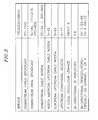
- other intentional signalssuch as cable modems or set top box conditional access signals may be present. Examples of the several signals of services and frequencies that may be present on household coaxial cable and may interfere with each other are shown in FIG. 2 .
- Older built-in TV tunerscan generate significant amounts of intermediate frequency (IF) egress out of their antenna/cable TV F-connectors. Televisions that are directly connected to the coaxial cable may cause some interference to the HPNA signals on the coaxial cable.
- IFintermediate frequency
- HPNA home networking systemdepicted in FIG. 1
- HPNA home networking systemdepicted in FIG. 1
- the present inventionprovides a solution to meet such need.
- a method and apparatusfor coupling a system propagating home networking communications signals over telephone lines to a system propagating television signals over a coaxial cable system to a television device.
- a three port adapterhas a phone line port, a first coaxial cable port and a second coaxial cable port.
- the first coaxial cable portis coupled to the phone line port through a low pass filter and wideband balun adapted to pass home networking communications signals while being adapted to reject television signals.
- the first coaxial cable portis also coupled to the second coaxial port through a high pass filter while being adapted to reject home networking communications signals.
- the phone line portis coupled to the system propagating home networking communications signals.
- the first coaxial cable portis coupled to the system propagating television signals over coaxial cable.
- the second coaxial cable portis coupled to the television device.
- the three port adapterincludes a DC bypass path between the first coaxial port and the second coaxial cable port.
- the low pass filterpasses signals in the 4 to 30 MHz band and the high pass filter passes signals greater than 30 MHz.
- the wideband balunincludes a transformer for matching 75 ohm coaxial cable to an approximately 100 ohm to 135 ohm twisted, untwisted, shielded or unshielded wire pair.
- the wire paircan be a phone line.
- a method and apparatus for splitting television signals propagating over a coaxial cable systemhas a first coaxial cable port, a second coaxial cable port and a third coaxial cable port.
- the first coaxial cable portsplits power between the second coaxial port and the third coaxial port through a ferrite bead splitter.
- the first coaxial cable port, the second coaxial cable port and the third coaxial cable portare coupled to each other through an inductor/capacitor circuit adapted to provide a low loss path there between at frequencies propagating home networking communication signals.
- HPNA 2.016/32 Mbps home networking communication signal technology sharing a home's existing coaxial cable provides high-speed networking for delivery of high quality digital video, voice over IP (VoIP) and shared broadband Internet access throughout the house without adding any new wires.
- HPNA 2.0can be added to the existing coaxial cable and be totally compatible with the existing cable TV or off-air TV signals. Additionally, HPNA 2.0 nodes are relatively inexpensive. Further, as more bandwidth is required, future HPNA standards that provide up to 100 Mbps could be employed over exactly the same network infrastructure, offering a simple upgrade path for future services such as high definition television.
- FIG. 1shows in block diagram form a general home networking environment within which the present invention can be implemented.
- FIG. 2shows in table format examples of several signals of services and frequencies that may be present on household coaxial cable and which may interfere with each other.
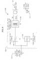
- FIG. 3is one embodiment implementing the present invention.
- FIG. 4shows in block diagram form a three port adapter in accordance with the present invention.
- FIG. 5shows the three port adapter of FIG. 4 in schematic form.
- FIGS. 6 a and 6 bshow the coax port to HPNA port frequency response of the three port adapter depicted in FIGS. 4 and 5 .
- FIG. 7shows the coax port to TV port frequency response of the three port adapter depicted in FIGS. 4 and 5 .
- FIGS. 8 a and 8 bshow the TV port to HPNA port frequency response of the three port adapter depicted in FIGS. 4 and 5 .
- FIG. 9is a schematic diagram of a bypass splitting adapter in accordance with the present invention.
- FIGS. 10 a and 10 bshow typical customer premises coaxial cable environments.
- FIG. 11shows an embodiment in accordance with the present invention.
- FIG. 12shows a further embodiment in accordance with the present invention.
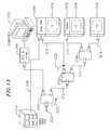
- FIG. 13shows still another embodiment in accordance with the present invention.
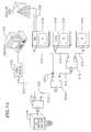
- FIG. 14shows a still further embodiment in accordance with the present invention.
- FIG. 15is still another embodiment in accordance with the present invention.
- FIG. 16is yet another embodiment in accordance with the present invention.
- System 100includes computer 14 , which can transmit and receive data in accordance with the HPNA protocol, and televisions 102 are interconnected over a coaxial cable transmission medium to Cable TV Network Feed 104 .
- computer 14can transmit and receive data in accordance with the HPNA protocol
- televisions 102are interconnected over a coaxial cable transmission medium to Cable TV Network Feed 104 .
- broadband access pointat the home entertainment center via cable modem/set top box 106 and with an in-home network emanating from that point, it becomes possible to provide high-quality digital streaming video, VoIP and Internet access services throughout the home.
- a simple wayis provided to transport digital media using HPNA 2.0 traffic over 75 ⁇ coaxial cable, in addition to phone cable as described above and shown in FIG.
- Adapters 108splice and match the HPNA signal into the coaxial cable, e.g., RG-6/59.
- the HPNA signalwill coexist on the coaxial cable with most existing cable TV or off-air TV transmissions.
- dedicated coaxcan be run from the point of entry to the DOCSIS cable modem or conditional access set top box.
- adapters 108described in more detail below, are simple passive three port devices which allow the HPNA 2.0 signals to coexist on the coaxial cable.
- an inexpensive HPNA bandpass splitter device 110is provided, also described in more detail below.
- Video unit 114receives and decodes a full-bandwidth MPEG2 video stream from cable modem/set top box 106 .
- Cable modem/set top box 106interfaces with adapter 108 through Ethernet to HPNA bridge 116 .
- adapter 108is shown in block diagram form.
- Adapter 108is used, one per phone cable based HPNA node on the coaxial cable system, to splice and impedance match the HPNA signal onto the coaxial cable.
- Adapter 108(also identified as an HPNA to Coax Tap, or HCT) is a simple passive three port diplexer/balun device with coax to coax DC bypass.
- Adapter 108includes HPNA—RJ11 connector port 120 , Coax (to wall)—‘F’ type RF connector port 122 , and TV—‘F’ type RF connector port 124 .
- the electrical characteristics between the portsare as follows. There is isolation between the TV port 124 and HPNA port 120 .
- the HPNA portincludes transformer/balun 132 to match the 75 ohm of the coaxial cable to the 135 ohm of the HPNA node.
- Adapter 108 as shown in FIG. 4is shown in more detail schematically in FIG. 5 .
- Transformer 132has windings of 8t:6t of 26 awg coated copper wire on an Amidon FT23-43 core (or the like). This impedance matches the 135 ohm phone line of HPNA port 120 to the 75 ohm coax port 122 while simultaneously performing a balun function.
- Diplexer 126is formed by the 82 pF capacitor C 1 /0.39 uH inductor L 2 and 82 pF capacitor C 2 /0.39 uH inductor combination.
- a preferred diplexer cross-over frequencyis 27.4 MHz, which is a convenient frequency between the top of the HPNA band and the bottom of the TV/Cable band.
- 0.01 uF capacitors C 3 , C 4 , C 8 and C 9provide DC blocking.
- 0.39 uH 350 mA miniature inductor L 4provides a DC bypass between coax port 122 and TV port 124 .
- Inductor L 4 's 350 mA minimum current ratingallows up to 0.5A to pass between these ports without saturating inductor L 4 .
- the component valuesmay be adjusted for circuit optimization.
- FIGS. 6 a and 6 bshow the coax port to HPNA port frequency response of HCT adapter 108 .
- FIG. 6 ais for 0-10 MHz
- FIG. 6 bis for 0-500 MHz.
- FIG. 7shows the coax port to TV port frequency response of HCT adapter 108 for 0-500 MHz. There is very low loss (less than 1 dB) above 50 MHz between the coax port and TV port. Also it should be noted that there is good isolation between these two ports in the HPNA band. This will prevent stray IF interference from the TV from affecting the HPNA on the coaxial cable.
- FIGS. 8 a and 8 bshow the TV port to HPNA port frequency response of HCT adapter 108 .
- FIG. 8 ais for 0-10 MHz
- FIG. 8 bis for 0-500 MHz.
- the worst case (at the diplexer crossover frequency of 30 MHz)is still better than 6 dB.
- bypass splitting adapter 110is shown center line 3 L of the cylindrical piston bore 3 , the distance D 1 from the base portion of the reed valve element 35 to the center while also providing a bypass for HPNA frequencies between all ports.
- Bypass splitting adapter 110replaces conventional RF splitters in wiring situations where there are multiple levels of RF splitters.
- Conventional RF splittersfound in nearly all home coaxial cable wiring systems, have significant isolation (loss) between its output ports at frequencies above a 2 or 3 MHz. Since HPNA adapters use frequencies above 4 MHz, conventional RF splitters need to have an additional bandpass function.
- bypass splitting adapter 110is a conventional splitter with extra passive components added to provide a bypass for the HPNA frequencies between all ports on the splitter.
- Ferrite bead splitterprovides the power split function with isolation between the two output ports 142 a , 142 b at VHF/UHF, while three 0.39 ⁇ H inductors 144 a , 144 b , 144 c and 82 pF capacitor 146 provide a low-loss path between all three ports 142 a , 142 b , 142 c for HPNA signals.
- 0.39 ⁇ H inductors 144 a , 144 b , 144 c and 82 pF capacitor 146provide a low-loss path between all three ports 142 a , 142 b , 142 c for HPNA signals.
- FIGS. 10 a and 10 bRepresentative typical environments within which the present invention can be most useful are shown referring to FIGS. 10 a and 10 b . Although there are many possible scenarios in homes, the embodiments of the present invention set forth in FIGS. 11-16 are representative of typical scenarios including systems which may have installations of an entertainment (e.g. Direct Broadcast System (DBS), Multi Service Operator (MSO)) system that uses HPNA over coaxial cable.
- an entertainmente.g. Direct Broadcast System (DBS), Multi Service Operator (MSO)
- MSOMulti Service Operator
- FIG. 10 atypical home coaxial cable installation 200 is shown.
- Two levels of splitters 210 a , 210 bfeed coaxial cables 212 to most rooms in the house, connecting cable head end 214 with televisions 216 .
- an additional splitter tier 210 c for connecting cable head end 214 through additional cable 212 a and cable modem 230 to computer 232is added to the system of FIG. 10 a.
- FIG. 11the existing cable broadcast services shown in FIG. 10 a is replaced with DBS 218 .
- Video NIC device 219is included, wherein a full bandwidth MPEG2 video stream is desired to be received and decoded.
- “X” 220indicates where the exiting cable is cut.
- Arrow 222indicates where a splitter is reoriented.
- a housewill only use either cable TV or an off-air antenna but not both, since that would require doubling up every coaxial cable run in the house.
- the “top of the tree” pointis a point of entry where the cable TV or antenna gets fed into the house's coaxial wiring plant. This is usually at the top of the splitter tree 210 a , 210 b .
- RF splitterscan be two-, three- or four-way devices. They are simple passive devices that have about 4 dB split loss per two way split and about 10 dB of isolation between the output ports per two way split over a frequency range from below 5 MHz to above 500 MHz. Two-way splitters have the least split loss and isolation. Internally, three- and four-way splitters use multiple cascaded two-way splitters to achieve the multi-way split. A three-way splitter consists of 2 two-way splitters and a four-way splitter consists of 3 two-way splitters.
- a four-way splitterhas about 8 dB loss per split and about 20 dB isolation between the extremities of the splitter tree.
- Path loss of 4 db per two-way split down the splitter tree from the topis acceptable for HPNA 2.0 which will work at full rate up to about 28 dB attenuation.
- the attenuation of the coaxial cable (RG-6 or RG-59) 212 at HPNA frequencies (4 to 10 MHz) over the typical distances found in a homeis insignificant.
- the worst case coax path loss from the end of any one coaxial cable to anotherwould only be 14 dB.
- HPNA over coaxial cablecan distribute digital data over the coaxial cable used to distribute the cable content.
- Architectures with MSO servicesgenerally require one extra run of coaxial cable to the new main STB and possible reorientation of some of the existing splitters. This allows the existing coaxial cable to be reused with the main STB becoming the top of the distribution tree.
- Main STB 240does not include a DOCSIS cable modem.
- Contentis transmitted from cable headend 214 to main STB 240 using new coaxial cable run 242 and the existing coaxial cable tree is used to distribute digital data from the main STB as well as relay the RF content through the main STB.
- Any DOCSIS cable modems 230use existing coaxial cable separate from the HPNA over coaxial cable network.
- main STB 240does contain DOCSIS cable modem functionality, existing cable modem 230 becomes redundant. In these types of scenarios, the existing coaxial cable is used to distribute digital data from main STB 240 using HPNA.
- Existing cable modem 230 as seen in FIG. 12is replaced with an HCT and a HPNA adapter 244 as shown in FIG. 13 .
- contentis transmitted from cable headend 214 to main STB using new coaxial cable run 246 and the existing coaxial cable tree is used to distribute digital data from the main STB as well as relay the RF content through the main STB.
- the scenario shownis similar to the DBS scenario shown in FIG. 11 except that the customer retains cable modem service in addition to DBS content.
- the topologyis similar except that the cabling for cable modem 230 is separated from the other coaxial cabling.
- FIG. 15there is shown a typical topology for a home that receives content via a DSL provider 250 .
- the DSL access lineis terminated in DSL modem with a residential gateway (router) 252 .
- Existing telephone wiring 254can be used to connect computer device.
- An HCT adapter 256is added to bridge the telephone wiring to the coaxial cable wiring 212 in which digital video signals can be distributed to STBs/Video NICs 219 .
- FIG. 16another embodiment of the present invention is shown wherein a system having cable head 214 , cable modem 230 /computer 323 , DBS system 218 , Video NIC 219 , and televisions 216 is provided that combines the use of the HCT adapter 108 as depicted in FIGS. 4 and 5 , HBS splitter 110 as depicted in FIG. 9 and includes IF TV noise filter (ITF) 260 .
- HBS 110replaces splitter 210 a of FIG. 13 .
- HCT adapter 308 ainterfaces between DBS 218 , television 316 a and HBS adapter 110 .
- HCT adapter 308 binterfaces between Video NIC 219 , television 316 b and an output port of splitter 210 b .
- ITF 260is coupled between an other output port of splitter 210 b and television 316 c .
- ITF 260mitigates Intermediate Frequency TV noise that may be coupled onto the coaxial cable from the input F-connector on a television. IF noise typically is centered around 6 MHz which fails directly in the 4 to 10 MHz HPNA band.
- ITF 260is a 2-port device with two F-type 750 connectors on it, one for the Coax connection (wall) and the other for the TV. A third port would be internal to the device (the “HPNA” port) and be terminated with a resistor. ITF 260 would direct all energy from the TV below 30 MHz into the internal terminated port, thus, no interfering energy in the HPNA band would appear on the coax port.
Landscapes
- Engineering & Computer Science (AREA)
- Signal Processing (AREA)
- Multimedia (AREA)
- Automation & Control Theory (AREA)
- Computer Networks & Wireless Communication (AREA)
- General Engineering & Computer Science (AREA)
- Cable Transmission Systems, Equalization Of Radio And Reduction Of Echo (AREA)
- Two-Way Televisions, Distribution Of Moving Picture Or The Like (AREA)
Abstract
Description
Claims (8)
Priority Applications (1)
| Application Number | Priority Date | Filing Date | Title |
|---|---|---|---|
| US10/150,187US8296817B2 (en) | 2001-05-17 | 2002-05-16 | Apparatus for transporting home networking frame-based communications signals over coaxial cables |
Applications Claiming Priority (2)
| Application Number | Priority Date | Filing Date | Title |
|---|---|---|---|
| US29177001P | 2001-05-17 | 2001-05-17 | |
| US10/150,187US8296817B2 (en) | 2001-05-17 | 2002-05-16 | Apparatus for transporting home networking frame-based communications signals over coaxial cables |
Publications (2)
| Publication Number | Publication Date |
|---|---|
| US20020174423A1 US20020174423A1 (en) | 2002-11-21 |
| US8296817B2true US8296817B2 (en) | 2012-10-23 |
Family
ID=23121751
Family Applications (1)
| Application Number | Title | Priority Date | Filing Date |
|---|---|---|---|
| US10/150,187Expired - Fee RelatedUS8296817B2 (en) | 2001-05-17 | 2002-05-16 | Apparatus for transporting home networking frame-based communications signals over coaxial cables |
Country Status (2)
| Country | Link |
|---|---|
| US (1) | US8296817B2 (en) |
| WO (1) | WO2002093758A2 (en) |
Cited By (2)
| Publication number | Priority date | Publication date | Assignee | Title |
|---|---|---|---|---|
| US20120303757A1 (en)* | 2008-03-27 | 2012-11-29 | Broadcom Corporation | Channel Frequency Reuse for Narrow Beam Video Streaming Based Upon Mobile Terminal Location Information |
| US20130156115A1 (en)* | 2011-12-14 | 2013-06-20 | Entropic Communications, Inc. | 10 Gbps Coaxial Cable Networking System |
Families Citing this family (80)
| Publication number | Priority date | Publication date | Assignee | Title |
|---|---|---|---|---|
| US6480510B1 (en) | 1998-07-28 | 2002-11-12 | Serconet Ltd. | Local area network of serial intelligent cells |
| US6956826B1 (en) | 1999-07-07 | 2005-10-18 | Serconet Ltd. | Local area network for distributing data communication, sensing and control signals |
| US6549616B1 (en) | 2000-03-20 | 2003-04-15 | Serconet Ltd. | Telephone outlet for implementing a local area network over telephone lines and a local area network using such outlets |
| US6842459B1 (en) | 2000-04-19 | 2005-01-11 | Serconet Ltd. | Network combining wired and non-wired segments |
| US9094226B2 (en) | 2000-08-30 | 2015-07-28 | Broadcom Corporation | Home network system and method |
| IL154695A0 (en) | 2000-08-30 | 2003-09-17 | Tiaris Inc | A home network system and method |
| US8724485B2 (en) | 2000-08-30 | 2014-05-13 | Broadcom Corporation | Home network system and method |
| US20050204066A9 (en)* | 2001-02-13 | 2005-09-15 | T.M.T. Third Millenium Technologies Ltd. | Cableran home networking over coaxial cables |
| US20020194605A1 (en)* | 2001-05-18 | 2002-12-19 | T.M.T. Third Millenium Technologies Ltd. | Cableran networking over coaxial cables |
| EP2234394A1 (en) | 2001-10-11 | 2010-09-29 | Mosaid Technologies Incorporated | Coupling device |
| US7693189B2 (en)* | 2002-10-17 | 2010-04-06 | Coppergate Communication Ltd. | HPNA hub |
| US6999433B2 (en)* | 2002-10-17 | 2006-02-14 | Coppergate Communication Ltd. | Method of reducing near-end crosstalk in an MxU networking architecture |
| IL152824A (en) | 2002-11-13 | 2012-05-31 | Mosaid Technologies Inc | Addressable outlet and a network using same |
| IL154921A (en) | 2003-03-13 | 2011-02-28 | Mosaid Technologies Inc | Telephone system having multiple distinct sources and accessories therefor |
| WO2004107113A2 (en)* | 2003-05-22 | 2004-12-09 | Coaxsys, Inc. | Networking methods and apparatus |
| IL157787A (en) | 2003-09-07 | 2010-12-30 | Mosaid Technologies Inc | Modular outlet for data communications network |
| KR100787216B1 (en)* | 2003-08-06 | 2007-12-21 | 삼성전자주식회사 | Digital entertainment systems |
| CN1898660B (en) | 2003-12-01 | 2014-06-25 | 美商内数位科技公司 | User Initiated Handover Based on Session Initiation Protocol |
| IL159838A0 (en) | 2004-01-13 | 2004-06-20 | Yehuda Binder | Information device |
| IL160417A (en) | 2004-02-16 | 2011-04-28 | Mosaid Technologies Inc | Outlet add-on module |
| FR2873251B1 (en)* | 2004-07-16 | 2006-10-27 | Legrand Sa | SYSTEM FOR DISTRIBUTING TELEVISION SIGNALS AND LOCAL COMPUTER NETWORK SIGNALS |
| US20060225119A1 (en)* | 2005-03-31 | 2006-10-05 | Wollmershauser Steven M | VDSL splitter |
| US8040235B2 (en)* | 2005-04-08 | 2011-10-18 | Panasonic Corporation | Relay apparatus and electric appliance |
| US20070016933A1 (en)* | 2005-07-13 | 2007-01-18 | Wollmershauser Steven M | RF signal injector |
| US7808985B2 (en)* | 2006-11-21 | 2010-10-05 | Gigle Networks Sl | Network repeater |
| US20080159358A1 (en)* | 2007-01-02 | 2008-07-03 | David Ruiz | Unknown Destination Traffic Repetition |
| EP1770870B1 (en)* | 2005-10-03 | 2019-04-03 | Avago Technologies International Sales Pte. Limited | Powerline communication device and method |
| US8213895B2 (en)* | 2005-10-03 | 2012-07-03 | Broadcom Europe Limited | Multi-wideband communications over multiple mediums within a network |
| US20070076666A1 (en)* | 2005-10-03 | 2007-04-05 | Riveiro Juan C | Multi-Wideband Communications over Power Lines |
| US8406239B2 (en)* | 2005-10-03 | 2013-03-26 | Broadcom Corporation | Multi-wideband communications over multiple mediums |
| US7635270B2 (en)* | 2006-05-31 | 2009-12-22 | At&T Intellectual Property I, L.P. | Method and apparatus for transferring digital packet-based data |
| US7860146B2 (en)* | 2006-07-06 | 2010-12-28 | Gigle Networks, Inc. | Adaptative multi-carrier code division multiple access |
| US8885814B2 (en)* | 2006-07-25 | 2014-11-11 | Broadcom Europe Limited | Feedback impedance control for driving a signal |
| US7697522B2 (en) | 2006-11-20 | 2010-04-13 | Broadcom Corporation | Systems and methods for aggregation of packets for transmission through a communications network |
| US7742495B2 (en) | 2006-11-20 | 2010-06-22 | Broadcom Corporation | System and method for retransmitting packets over a network of communication channels |
| US7782850B2 (en)* | 2006-11-20 | 2010-08-24 | Broadcom Corporation | MAC to PHY interface apparatus and methods for transmission of packets through a communications network |
| US8090043B2 (en) | 2006-11-20 | 2012-01-03 | Broadcom Corporation | Apparatus and methods for compensating for signal imbalance in a receiver |
| US20080159414A1 (en)* | 2006-12-28 | 2008-07-03 | Texas Instruments Incorporated | Apparatus for and method of baseline wander mitigation in communication networks |
| CN101227295B (en)* | 2007-01-15 | 2011-02-02 | 杭州华三通信技术有限公司 | Ethernet transmission method and Ethernet transmitting/receiving device based on coaxial cable network |
| US8345553B2 (en) | 2007-05-31 | 2013-01-01 | Broadcom Corporation | Apparatus and methods for reduction of transmission delay in a communication network |
| US20090165070A1 (en)* | 2007-12-19 | 2009-06-25 | Broadcom Corporation | SYSTEMS AND METHODS FOR PROVIDING A MoCA COMPATABILITY STRATEGY |
| KR20110015001A (en)* | 2008-05-02 | 2011-02-14 | 톰슨 라이센싱 | Reflector Device for Video Home Network |
| US8098770B2 (en) | 2008-05-06 | 2012-01-17 | Broadcom Corporation | Unbiased signal-to-noise ratio estimation for receiver having channel estimation error |
| US9363469B2 (en) | 2008-07-17 | 2016-06-07 | Ppc Broadband, Inc. | Passive-active terminal adapter and method having automatic return loss control |
| US9112717B2 (en) | 2008-07-31 | 2015-08-18 | Broadcom Corporation | Systems and methods for providing a MoCA power management strategy |
| US8325691B2 (en)* | 2008-09-26 | 2012-12-04 | Optical Cable Corporation | Method and apparatus for providing wireless communications within a building |
| US7956689B2 (en)* | 2008-10-13 | 2011-06-07 | Broadcom Corporation | Programmable gain amplifier and transconductance compensation system |
| US10154302B2 (en) | 2008-10-13 | 2018-12-11 | Ppc Broadband, Inc. | CATV entry adapter and method for distributing CATV and in-home entertainment signals |
| US8356322B2 (en)* | 2009-09-21 | 2013-01-15 | John Mezzalingua Associates, Inc. | Passive multi-port entry adapter and method for preserving downstream CATV signal strength within in-home network |
| US8429695B2 (en) | 2008-10-21 | 2013-04-23 | Ppc Broadband, Inc. | CATV entry adapter and method utilizing directional couplers for MoCA signal communication |
| US7795973B2 (en) | 2008-10-13 | 2010-09-14 | Gigle Networks Ltd. | Programmable gain amplifier |
| US9351051B2 (en) | 2008-10-13 | 2016-05-24 | Ppc Broadband, Inc. | CATV entry adapter and method for distributing CATV and in-home entertainment signals |
| US8286209B2 (en)* | 2008-10-21 | 2012-10-09 | John Mezzalingua Associates, Inc. | Multi-port entry adapter, hub and method for interfacing a CATV network and a MoCA network |
| US11910052B2 (en) | 2008-10-21 | 2024-02-20 | Ppc Broadband, Inc. | Entry device for communicating external network signals and in-home network signals |
| US8510782B2 (en) | 2008-10-21 | 2013-08-13 | Ppc Broadband, Inc. | CATV entry adapter and method for preventing interference with eMTA equipment from MoCA Signals |
| US9461760B2 (en)* | 2008-10-29 | 2016-10-04 | At&T Intellectual Property I, L.P. | Remediation of television signals using a network back-channel |
| US8238227B2 (en) | 2008-12-22 | 2012-08-07 | Broadcom Corporation | Systems and methods for providing a MoCA improved performance for short burst packets |
| US8254413B2 (en) | 2008-12-22 | 2012-08-28 | Broadcom Corporation | Systems and methods for physical layer (“PHY”) concatenation in a multimedia over coax alliance network |
| US8213309B2 (en) | 2008-12-22 | 2012-07-03 | Broadcom Corporation | Systems and methods for reducing latency and reservation request overhead in a communications network |
| US8553547B2 (en) | 2009-03-30 | 2013-10-08 | Broadcom Corporation | Systems and methods for retransmitting packets over a network of communication channels |
| US20100254278A1 (en) | 2009-04-07 | 2010-10-07 | Broadcom Corporation | Assessment in an information network |
| US8730798B2 (en) | 2009-05-05 | 2014-05-20 | Broadcom Corporation | Transmitter channel throughput in an information network |
| GB0908815D0 (en)* | 2009-05-22 | 2009-07-01 | Technetix Plc | Signal splitter for use in MoCA/CATV networks |
| US8867355B2 (en) | 2009-07-14 | 2014-10-21 | Broadcom Corporation | MoCA multicast handling |
| US8942250B2 (en) | 2009-10-07 | 2015-01-27 | Broadcom Corporation | Systems and methods for providing service (“SRV”) node selection |
| US8350641B2 (en)* | 2010-01-26 | 2013-01-08 | John Mezzalingua Associates, Inc. | Band selective isolation bridge for splitter |
| US8487717B2 (en) | 2010-02-01 | 2013-07-16 | Ppc Broadband, Inc. | Multipath mitigation circuit for home network |
| US8611327B2 (en) | 2010-02-22 | 2013-12-17 | Broadcom Corporation | Method and apparatus for policing a QoS flow in a MoCA 2.0 network |
| US8514860B2 (en) | 2010-02-23 | 2013-08-20 | Broadcom Corporation | Systems and methods for implementing a high throughput mode for a MoCA device |
| US8479247B2 (en) | 2010-04-14 | 2013-07-02 | Ppc Broadband, Inc. | Upstream bandwidth conditioning device |
| US8561125B2 (en) | 2010-08-30 | 2013-10-15 | Ppc Broadband, Inc. | Home network frequency conditioning device and method |
| IL209140A0 (en)* | 2010-11-04 | 2011-01-31 | Tangotec Ltd | A passive adapter for home networks |
| WO2012088350A2 (en) | 2010-12-21 | 2012-06-28 | John Mezzalingua Associates, Inc. | Method and apparatus for reducing isolation in a home network |
| US9264012B2 (en) | 2012-06-25 | 2016-02-16 | Ppc Broadband, Inc. | Radio frequency signal splitter |
| US20140233562A1 (en)* | 2013-02-21 | 2014-08-21 | Inango Systems Ltd. | System and method for point-to-multipoint communication |
| DE102014206448A1 (en)* | 2014-04-03 | 2015-10-08 | Deutsche Telekom Ag | Method for the coaxial transmission of digital VDSL signals |
| CA3028756A1 (en) | 2016-06-30 | 2018-01-04 | Ppc Broadband, Inc. | Passive enhanced moca entry device |
| TWI641217B (en)* | 2017-09-15 | 2018-11-11 | 瑞柯科技股份有限公司 | Electronic apparatus with power over coaxial cable function |
| WO2019143613A2 (en) | 2018-01-19 | 2019-07-25 | Ppc Broadband, Inc. | Systems and methods for extending an in-home splitter network |
| US10971871B2 (en)* | 2019-03-26 | 2021-04-06 | Ixi Technology Holdings, Inc. | Connector adaptation with impedance matching |
Citations (12)
| Publication number | Priority date | Publication date | Assignee | Title |
|---|---|---|---|---|
| US4125810A (en)* | 1977-04-08 | 1978-11-14 | Vari-L Company, Inc. | Broadband high frequency baluns and mixer |
| US5027426A (en) | 1989-07-07 | 1991-06-25 | Chiocca Jr Joseph J | Signal coupling device and system |
| US5296823A (en)* | 1992-09-04 | 1994-03-22 | James Dietrich | Wideband transmission line balun |
| US5440335A (en) | 1993-05-28 | 1995-08-08 | U S West Advanced Technologies, Inc. | Method and apparatus for delivering passband and telephony signals in a coaxial cable network |
| US5642155A (en) | 1994-09-14 | 1997-06-24 | Cheng; Alexander L. | Method and apparatus for supporting two-way telecommunications on CATV networks |
| US5729824A (en) | 1994-12-09 | 1998-03-17 | Raychem Corporation | Distributed digital loop carriers system using coaxial cable |
| US5893024A (en)* | 1996-08-13 | 1999-04-06 | Motorola, Inc. | Data communication apparatus and method thereof |
| US6118974A (en)* | 1997-02-06 | 2000-09-12 | Jennison Holding, Inc. | CEBus node zero switching device |
| US6144399A (en)* | 1999-03-25 | 2000-11-07 | Mediaone Group, Inc. | Passive system used to merge telephone and broadband signals onto one coaxial cable |
| US20020059642A1 (en)* | 2000-11-14 | 2002-05-16 | Russ Samuel H. | Networked subscriber television distribution |
| US6418149B1 (en)* | 1999-12-07 | 2002-07-09 | Next Level Communications, L.P. | Bi-directional premises wiring system and method |
| US6574236B1 (en)* | 1999-05-18 | 2003-06-03 | Qwest Communications International Inc. | Interface device having VDSL splitter and interference filter |
- 2002
- 2002-05-16WOPCT/US2002/015643patent/WO2002093758A2/enactiveApplication Filing
- 2002-05-16USUS10/150,187patent/US8296817B2/ennot_activeExpired - Fee Related
Patent Citations (12)
| Publication number | Priority date | Publication date | Assignee | Title |
|---|---|---|---|---|
| US4125810A (en)* | 1977-04-08 | 1978-11-14 | Vari-L Company, Inc. | Broadband high frequency baluns and mixer |
| US5027426A (en) | 1989-07-07 | 1991-06-25 | Chiocca Jr Joseph J | Signal coupling device and system |
| US5296823A (en)* | 1992-09-04 | 1994-03-22 | James Dietrich | Wideband transmission line balun |
| US5440335A (en) | 1993-05-28 | 1995-08-08 | U S West Advanced Technologies, Inc. | Method and apparatus for delivering passband and telephony signals in a coaxial cable network |
| US5642155A (en) | 1994-09-14 | 1997-06-24 | Cheng; Alexander L. | Method and apparatus for supporting two-way telecommunications on CATV networks |
| US5729824A (en) | 1994-12-09 | 1998-03-17 | Raychem Corporation | Distributed digital loop carriers system using coaxial cable |
| US5893024A (en)* | 1996-08-13 | 1999-04-06 | Motorola, Inc. | Data communication apparatus and method thereof |
| US6118974A (en)* | 1997-02-06 | 2000-09-12 | Jennison Holding, Inc. | CEBus node zero switching device |
| US6144399A (en)* | 1999-03-25 | 2000-11-07 | Mediaone Group, Inc. | Passive system used to merge telephone and broadband signals onto one coaxial cable |
| US6574236B1 (en)* | 1999-05-18 | 2003-06-03 | Qwest Communications International Inc. | Interface device having VDSL splitter and interference filter |
| US6418149B1 (en)* | 1999-12-07 | 2002-07-09 | Next Level Communications, L.P. | Bi-directional premises wiring system and method |
| US20020059642A1 (en)* | 2000-11-14 | 2002-05-16 | Russ Samuel H. | Networked subscriber television distribution |
Cited By (4)
| Publication number | Priority date | Publication date | Assignee | Title |
|---|---|---|---|---|
| US20120303757A1 (en)* | 2008-03-27 | 2012-11-29 | Broadcom Corporation | Channel Frequency Reuse for Narrow Beam Video Streaming Based Upon Mobile Terminal Location Information |
| US8494440B2 (en)* | 2008-03-27 | 2013-07-23 | Broadcom Corporation | Channel frequency reuse for narrow beam video streaming based upon mobile terminal location information |
| US20130156115A1 (en)* | 2011-12-14 | 2013-06-20 | Entropic Communications, Inc. | 10 Gbps Coaxial Cable Networking System |
| US8792565B2 (en)* | 2011-12-14 | 2014-07-29 | Entropic Communications, Inc. | 10 Gbps coaxial cable networking system |
Also Published As
| Publication number | Publication date |
|---|---|
| WO2002093758A2 (en) | 2002-11-21 |
| US20020174423A1 (en) | 2002-11-21 |
| WO2002093758A3 (en) | 2003-09-04 |
Similar Documents
| Publication | Publication Date | Title |
|---|---|---|
| US8296817B2 (en) | Apparatus for transporting home networking frame-based communications signals over coaxial cables | |
| US20040187156A1 (en) | Transporting home networking frame-based communication signals over coaxial cables | |
| US10257566B2 (en) | Broadband local area network | |
| US6637030B1 (en) | Broadband cable television and computer network | |
| US6941576B2 (en) | System and methods for home network communications | |
| US8705417B2 (en) | In-network home gateway for hybrid fiber-coax network | |
| US20050034159A1 (en) | Implementing a hybrid wireless and coaxial cable network | |
| US20030012365A1 (en) | Twisted pair communication system | |
| US20120054805A1 (en) | Home network frequency conditioning device | |
| US20130081096A1 (en) | Cable television entry adapter | |
| US10917685B2 (en) | Entry device for communicating signals between an external network and an in-home network | |
| KR20020095202A (en) | Architecture and method for automatic distributed gain control for modem communications over passive multipoint networks | |
| WO2001080030A1 (en) | System and methods for home network communications | |
| US20050175035A1 (en) | Method and system for providing DOCSIS service over a passive optical network | |
| JP2002509668A (en) | Twisted pair communication system | |
| US20130283334A1 (en) | Cable Modem for Supporting Multimedia Over Coax Alliance and Data Over Cable Service Interface Specification Standards | |
| US7841871B2 (en) | Methods and apparatus for transferring digital packet-based data | |
| US20230254443A1 (en) | Passive entry adapter system for a catv network | |
| EP1125385A1 (en) | In-home network using an existing coaxial cable installation | |
| Kos et al. | New services over CATV network | |
| CA2290001A1 (en) | Twisted pair communication system | |
| KR20030026350A (en) | Capacity scaling and functional element redistribution within an in-building coax cable internet access system |
Legal Events
| Date | Code | Title | Description |
|---|---|---|---|
| AS | Assignment | Owner name:BROADCOM HOMENETWORKING, INC., CALIFORNIA Free format text:ASSIGNMENT OF ASSIGNORS INTEREST;ASSIGNORS:FIFIELD, DAVID;TRACHEWSKY, JASON ALEXANDER;HOLLOWAY, JOHN T.;REEL/FRAME:012913/0822;SIGNING DATES FROM 20020514 TO 20020515 Owner name:BROADCOM HOMENETWORKING, INC., CALIFORNIA Free format text:ASSIGNMENT OF ASSIGNORS INTEREST;ASSIGNORS:FIFIELD, DAVID;TRACHEWSKY, JASON ALEXANDER;HOLLOWAY, JOHN T.;SIGNING DATES FROM 20020514 TO 20020515;REEL/FRAME:012913/0822 | |
| AS | Assignment | Owner name:BROADCOM CORPORATION, CALIFORNIA Free format text:MERGER;ASSIGNOR:BROADCOM HOMENETWORKING, INC.;REEL/FRAME:014363/0596 Effective date:20030530 | |
| AS | Assignment | Owner name:BANK OF AMERICA, N.A., AS COLLATERAL AGENT, NORTH CAROLINA Free format text:PATENT SECURITY AGREEMENT;ASSIGNOR:BROADCOM CORPORATION;REEL/FRAME:037806/0001 Effective date:20160201 Owner name:BANK OF AMERICA, N.A., AS COLLATERAL AGENT, NORTH Free format text:PATENT SECURITY AGREEMENT;ASSIGNOR:BROADCOM CORPORATION;REEL/FRAME:037806/0001 Effective date:20160201 | |
| REMI | Maintenance fee reminder mailed | ||
| LAPS | Lapse for failure to pay maintenance fees | ||
| STCH | Information on status: patent discontinuation | Free format text:PATENT EXPIRED DUE TO NONPAYMENT OF MAINTENANCE FEES UNDER 37 CFR 1.362 | |
| FP | Lapsed due to failure to pay maintenance fee | Effective date:20161023 | |
| AS | Assignment | Owner name:AVAGO TECHNOLOGIES GENERAL IP (SINGAPORE) PTE. LTD., SINGAPORE Free format text:ASSIGNMENT OF ASSIGNORS INTEREST;ASSIGNOR:BROADCOM CORPORATION;REEL/FRAME:041706/0001 Effective date:20170120 Owner name:AVAGO TECHNOLOGIES GENERAL IP (SINGAPORE) PTE. LTD Free format text:ASSIGNMENT OF ASSIGNORS INTEREST;ASSIGNOR:BROADCOM CORPORATION;REEL/FRAME:041706/0001 Effective date:20170120 | |
| AS | Assignment | Owner name:BROADCOM CORPORATION, CALIFORNIA Free format text:TERMINATION AND RELEASE OF SECURITY INTEREST IN PATENTS;ASSIGNOR:BANK OF AMERICA, N.A., AS COLLATERAL AGENT;REEL/FRAME:041712/0001 Effective date:20170119 |