US8296719B2 - Software factory readiness review - Google Patents
Software factory readiness reviewDownload PDFInfo
- Publication number
- US8296719B2 US8296719B2US11/735,152US73515207AUS8296719B2US 8296719 B2US8296719 B2US 8296719B2US 73515207 AUS73515207 AUS 73515207AUS 8296719 B2US8296719 B2US 8296719B2
- Authority
- US
- United States
- Prior art keywords
- software
- project
- factory
- deliverable
- client
- Prior art date
- Legal status (The legal status is an assumption and is not a legal conclusion. Google has not performed a legal analysis and makes no representation as to the accuracy of the status listed.)
- Expired - Fee Related, expires
Links
Images


Classifications
- G—PHYSICS
- G06—COMPUTING OR CALCULATING; COUNTING
- G06Q—INFORMATION AND COMMUNICATION TECHNOLOGY [ICT] SPECIALLY ADAPTED FOR ADMINISTRATIVE, COMMERCIAL, FINANCIAL, MANAGERIAL OR SUPERVISORY PURPOSES; SYSTEMS OR METHODS SPECIALLY ADAPTED FOR ADMINISTRATIVE, COMMERCIAL, FINANCIAL, MANAGERIAL OR SUPERVISORY PURPOSES, NOT OTHERWISE PROVIDED FOR
- G06Q10/00—Administration; Management
Definitions
- the present disclosurerelates in general to the field of computers, and more particularly to the use of computer software. Still more particularly, the present disclosure relates to the creation of semi-custom software through the use of a standardized software factory.
- Off-the-shelf softwareis pre-developed software that has little, if any flexibility. Thus, the customer must tailor her activities to conform to the software. While such software is initially inexpensive compared to custom software, long-term costs (in time and money for software implementation, training, business process alterations, etc.) can be onerous in an enterprise environment.
- Custom softwareis custom built software that is tailored to existing or planned activities of the customer.
- the present disclosureprovides a computer-implemented method, system, and computer-readable medium for determining if a software factory is ready to take on a software project.
- the computer-implemented methodincludes the steps of: determining if an infrastructure for a software factory has been procured; determining if operational software needed to assemble work packets in an assembly line in the software factory has been installed; determining if a workflow event model for an assembly line in the software factory has been configured; determining if workload in the assembly line has been balanced; determining if communication channels between the software factory and a customer's computer system have been defined and cleared for data transmission; and in response to determining that any element described above has been determined not to have occurred, prohibiting an induction of a software project into the software factory.
- FIG. 1is an overview of a novel software factory
- FIG. 2is a flow-chart of steps taken to create custom software through the use of work packets in a software factory
- FIG. 3presents an overview of the life cycle of work packets
- FIG. 4presents an overview of an environment in which work packets are defined and assembled
- FIG. 5is a high-level flow-chart of steps taken to define and assemble work packets
- FIGS. 6 a - billustrate an exemplary header in a work packet
- FIG. 7is a high-level flow-chart of steps taken to archive a work packet
- FIG. 8is a high-level flow-chart of steps taken to rapidly on-board a software factory
- FIG. 9is a flow-chart of exemplary steps taken to induct a project.
- FIG. 10 ashows a relationship between pre-qualifying questions and checklists used to induct a project
- FIG. 10 a - edepict a Software Factory Packet Pattern Analysis and Predictive Forecasting Model that is used to dynamically generate checklists used to aid in the creation of work packets in the software factory;
- FIG. 11shows an environment in which software factory analytics and dashboards are implemented
- FIG. 12is a flow-chart showing exemplary steps taken to monitor a software factory
- FIG. 13illustrates an exemplary computer in which the present invention may be utilized
- FIGS. 14A-Bare flow-charts showing steps taken to deploy software capable of executing the steps described in FIGS. 1-12 ;
- FIGS. 15A-Bare flow-charts showing steps taken to execute the steps shown in FIGS. 1-12 using an on-demand service provider.
- a software factorywhich includes a collection of business and information Technology (IT) governance models, operational models, delivery methods, metrics, environment and tools bundled together to improve the quality of delivered software systems, control cost overruns, and effect timely delivery of such systems.
- ITinformation Technology
- the software factory described hereinoffers a practical solution to developing software systems using multiple sites that are geographically distributed. The issues of varying timezones and the hand-over between various teams residing in such timezones are handled by exchanging work packets.
- a work packetis a self-contained work unit that is composed of processes, roles, activities, applications and the necessary input parameters that allow a team to conduct a development activity in a formalized manner with visibility to progress of their effort afforded to the requesting teams.
- the novel software factory described hereinis a uniquely engineered scalable efficiency model construct that transforms a traditional software development art form into a repeatable scientific managed engineered streamline information supply chain.
- the software factoryincorporates applied system and industrial engineering quality assured efficiencies that provide for the waste eliminating, highly optimized performed instrumentation, measured monitoring and risk mitigated management of software development.
- the software factory 100is a service that interacts with both enterprise customers (i.e., client customers) 102 as well as enterprise partners (i.e., third party vendors) 104 .
- the primary human interface with the enterprise customers 102is through a Client Business Governance Board (CBGB) 106 .
- CBGB 106represents client stakeholders and client business sponsors that fund a project of the software factory 100 .
- CBGB 106can be an internal or external client.
- the same enterprisei.e., internal client
- a first enterprisei.e., external client
- a project proposal definitionis then run through a software factory induction process in a Software Factory Governance Board (SFGB) 108 and Software Factory Operations (SFO) 110 , where the project proposal definition is evaluated, qualified, scored and categorized.
- the project proposal definitionis then subject to a System Engineering Conceptual Requirements Review by the SFGB 108 . Based on the outcome of the review by the SFGB 108 , a decision is made to accept the project proposal definition or to send it back to the CBGB 106 for remediation and resubmission through the Software Factory Induction Process.
- Software Factory governancewhich includes SFGB 108 and SFO 110 , provides the guidance, constraints, and underlying enforcement of all the factory policies and procedures, in support of their governing principles in support of the strategic objects of the Software Factory 100 .
- Software Factory governanceconsists of factory business, IT and operations governance. The principles, policies and procedures of these models are carried out by two governing bodies—the Business Governance Board and the IT Governance Board (both part of SFGB 108 ), and an enforcement body—the Software Factory Operations 110 .
- the job of creating the custom softwareis sent to a Design Center 112 , where the project is broken into major functional areas, including those handled by a Requirements Analysis Team 114 and an Architectural Team 116 .
- the Requirements Analysis Team 114handles the Requirement Management side of the Design Center 112 , and is responsible for collecting the business requirements from the lines of business and populating these requirements into the tools. Analysis of business requirements is also carried out in order to derive associated IT requirements. Some requirements (e.g. system requirements) may have a contractual constraint to use a certain infrastructure. Requirements are analyzed and used in the bases for business modeling. These requirements and representative business (contextual, event and process models) are then verified with and signed off from project stakeholders. Requirements are then base-lined and managed within release and version control.
- the Architectural Side of the Design Center 112is handled by the Architecture Team 116 , which takes the output of the requirement/analysis/management side of the design center, and uses architectural decision factors (functional requirements, non-functional requirements, available technology, and constraints), to model a design with appropriate example representation into detail design specification, that is bundled with other pertinent factors into a work packet for assembly lines to execute.
- architectural decision factorsfunctional requirements, non-functional requirements, available technology, and constraints
- Work Packets 118are reusable, self-contained, discrete units of software code that constitute a contractual agreement that governs the relationship among Design Center 112 , Software Factory Governance Board 108 , Software Factory Operations 110 , and Assembly Line 120 . That is, each work packet 118 includes governance policies and procedures (e.g., including instructions for how work reports are generated and communicated to the client), standards (e.g., protocol for the work packet 118 ), reused assets (e.g., reusable blocks of code, including the requirements, instructions and/or links/pointers associated with those reusable blocks of code), work packet instructions (e.g., instructions for executing the work packet 118 ), integration strategy (e.g., how to integrate the work packet 118 into a client's security system), schedule (e.g., when deliverables are delivered to the client), exit criteria (e.g., a checklist for returning the work packet 118 and/or deliverables to the software factory 100 ), and Input/Output (I/O) work products (e
- Assembly Line(s) 120receive and execute the work packets 118 , which are specified by the Design Center 112 , to create a customized deliverable 122 .
- the assembly line 120puts the work packets 118 into a selected low-level design to generate a deliverable (executable product). While assembly line 120 can be a manual operation in which a coding person assembles and tests work packets, in another embodiment this process is automated using software that recognizes project types, and automatically assembles work packets needed for a recognized project type.
- Various testscan be performed in the assembly line 120 , including code/unit tests, integration test, system test, system integration test, and performance test.
- “Code/unit test”tests the deliverable for stand-alone bugs.
- “Integration test”tests the deliverable for compatibility with the client's system.
- System testchecks the client's system to ensure that it is operating properly.
- System integration testtests for bugs that may arise when the deliverable is integrated into the client's system.
- Perfectance testtests the deliverable as it is executing in the client's system. Note that if the deliverable is being executed on a service provider's system, then all tests described are obviously performed on the service provider's system rather than the client's system.
- a User Acceptance Test Team 124includes a client stakeholder that is charged with the responsibility of approving acceptance of deliverable 122 .
- Software factory 100may utilize enterprise partners 104 to provide human, hardware or software support in the generation, delivery and/or support of deliverables 122 .
- Such third party contractorsare viewed as a resource extension of the software factory 100 , and are governed under the same guidelines described above.
- an interface between the software factory 100 and the enterprise partner 104may be provided by a service provider's interface team 126 and/or a product vendor's interface team 128 .
- Service provided by an enterprise partner 104may be a constraint that is part of contractual agreement with a client to provide specialized services.
- An example of such a constraintis a required integrated information service component that is referenced in the integration design portion of the work packet 118 that is sent to assemble line 120 .
- third party service providersuse a standard integration strategy that is defined by the software factory 100 , and, as such, are subject to and obligated to operate under software factory governance.
- Product vendor's interface team 128provides an interface with a Product Vendor, which is an enterprise partner 104 that provides software factory 100 with supported products that maybe used within a software factory solution.
- Product Vendorsare also responsible for providing product support and maintaining vendor's relationships, which are managed under the software factory's governance guidelines.
- Support Team 130includes both Level 2 (L2) support and Level 1 (L1) support.
- L2 Supportis provided primarily by Software Engineers, who provide problem support of Software Factory produced delivered code for customers. That is, if a deliverable 122 doesn't run as designed, then the software engineers will troubleshoot the problem until it is fixed. These software engineers deliver technical assistance to Software Factory customers with information, tools, and fixes to prevent known software (and possibly hardware) problems, and provide timely responses to customer inquiries and resolutions to customer problems.
- L1 supportis primarily provided by an L1 Help Desk (Call Center).
- L1 Help Desk supportcan be done via self-service voice recognition and voice response, or by text chat to an automated smart attendant, or a call can be directed to a Customer Service Representative (CSR).
- Customer Service Representatives in this roleprovide first line of help problem support of Software Factory produced deliverables. Such help includes user instruction of known factory solution procedures.
- the L1 Help Deskwill provide preliminary problem identification, create trouble ticket entry into trouble tracking system, which then triggers a workflow event to dynamically route the problem issue to available and an appropriate L2 support group queue.
- initiator block 202which may be a creation of a contract between an enterprise client and a software factory service
- inputfrom a Client Business Governance Board
- a software factory(block 204 )
- This inputis a detailed description of the custom software needs of the enterprise client. While such input is usually prepared and presented by human management of the enterprise client, alternatively this input may be the creation of a Unified Modeling Language (UML) based description of the needed software.
- UMLUnified Modeling Language
- a project software proposal definitionis created by the Software Factory Governance Board of the software factory (block 206 ). This project software proposal definition is sent to the scheduling/dispatching department of the Software Factory Operations, which creates a software project.
- the software projectis then inducted (block 208 ).
- the project inductionprovides an initial introduction of the project to the software factory.
- checklistset al.
- the projectis initially evaluated. This evaluation includes determining if the software factory has the capacity, resources, bandwidth, etc. needed for the project. If so, then a determination is made as to whether the project is qualified for acceptance by the software factory.
- qualificationincludes, but is not limited to, determining if the project falls within the guidelines set by a Service Level Agreement (SLA) between the client enterprise and the software factory, whether the project conforms to legal guidelines such as Sarbanes-Oxley, etc.
- SLAService Level Agreement
- the projectis scored for feasibility, profitability, and desirability for implementation. If the induction process concludes that the project should proceed, then it is categorized into a particular type of project (e.g., payroll, inventory control, database management, marketing, et al.).
- a particular type of projecte.g., payroll, inventory control, database management, marketing, et al.
- the induction processdoes not pass (query block 210 ), indicating that the project should not proceed, then the project is returned to the Client Business Governance Board for additional discussions between the Client Business Governance Board and the software factory, in order to induct a revised project (i.e., reinduct the software project).
- the software projectis parsed into major functional areas (block 212 ). That is, the project is divided up (“broken apart”) in order to establish subunits that can later be integrated into a single custom software (“deliverable”).
- Work packetsare then obtained for all of the functional areas of the software project (block 214 ). These work packets are reusable components which are described in detail below.
- the work packetsare then stitched together (block 216 ) on an assembly line to create deliverable custom software that meets the criteria for the software project that has been established in the earlier steps.
- the custom softwareis then tested in the software factory (block 218 ). Once testing is completed, the custom software is delivered (block 220 ) to the client customer, who receives on-going support from the support team (block 222 ). The flow-chart ends at terminator block 224 .
- the software factoryuses work packets to blend software (including reusable artifacts), protocols (e.g., how software will be transmitted, how individuals will be contacted, etc.), governance requirements (e.g., service level agreements that describe how much a service will cost) and operating environments (hardware and software, including operating systems, integrated environments such as SAPTM, RationalTM, etc.) into a single integrated product, which can then be used in a stand-alone manner or can be fed into another system/product.
- softwareincluding reusable artifacts
- protocolse.g., how software will be transmitted, how individuals will be contacted, etc.
- governance requirementse.g., service level agreements that describe how much a service will cost
- operating environmentshardware and software, including operating systems, integrated environments such as SAPTM, RationalTM, etc.
- software factory 100is virtual. That is, the different components (e.g., software factory governance board 108 , software factory operations 110 , design center 112 , assembly line 120 ) may be located in different locations, and may operate independently under the control of information found in work packets 118 .
- each of the different components of the software factory 100publishes a set of services that the component can provide and a set of requirements for using these services. These services are functions that are well defined and made visible for outside entities to call.
- assembly line 120publishes a service that it can assemble only work packets that include code and protocol that utilize IBM's RationalTM software development platform.
- the assembly line 120has published its service (set of services includes “assembling work packets”) and the required protocol (set of requirements includes “utilize IBM's RationalTM software development platform”) to the design center 112 , which must decide if it wants (or is able) to utilize that particular assembly line 120 . If not, then another assembly line from another software factory may be called upon by the design center 112 .
- Behind each offered serviceare the actual processes that a component performs. These processes are steps taken by the service. Each step is performed by a section of software, or may be performed by an individual who has been assigned the task of performing this step. Each step utilizes leveraged tools, including the work packets 118 described herein. These work packets 118 then implement the process.
- FIG. 3There are five phases in the life cycle of a work packet, which are shown in FIG. 3 . These five phases are 1) Defining (block 302 ); 2) Assembling (block 304 ); Archiving (block 306 ); Distributing (block 308 ); and Pulling for execution (block 310 ). As indicated by the top dashed line coming out of asset repository 312 , this life cycle may be recursive. That is, in one embodiment, work packets are modified an upgraded in a recursive manner, which includes the steps shown in FIG. 3 . Once a work packet is assembled and archived, it is stored in an asset repository 312 , whence the work packet may be accessed and utilized by an asset manager 314 for assembly into a deliverable by an assembly line 316 .
- the assembly line 316can also send, to the asset manager 314 , a message 318 that requests a particular work packet 320 , which can be pulled (block 310 ) into the asset repository 312 by the asset manager 314 .
- This pulling step (block 310 )is performed through intelligent routing distribution (block 308 ) to the asset repository 312 and assembly line 316 .
- the configuration of the routing distribution of the work packet 320is managed by the asset manager 314 , which is software that indexes, stores and retrieve assets created and used with the software factory.
- a work packetis a self-contained work unit that comprises processes, roles, activities (parts of the job), applications, and necessary input parameters that allow a team to conduct a development activity in a formalized manner, with visibility to progress of their effort afforded to requesting teams.
- a work packetis NOT a deliverable software product, but rather is a component of a deliverable software product. That is, a work packet is processed (integrated into a system, tested, etc.) to create one or more deliverables. Deliverables, which were created from one or more work packets, are then combined into a custom software, such as an application, service or system.
- a work packetis composed of the following eight components.
- policies and proceduresinclude protocol definitions derived from a project plan. That is, a project plan for a particular custom software describes how work packets are called, as well as how work packets report back to the calling plan.
- this componentdescribes details about how work packets are implemented into a deliverable in a standardized manner. Examples of such standards are naming conventions, formatting protocol, etc.
- Reused Assetsthis component includes actual code, or at least pointers to code, that is archived for reuse by different assembled deliverables.
- Work Packet Instructionsthis component describes detailed instructions regarding how a work packet is actually executed. That is, work packet instructions document what work packets need to be built, and how to build them. These instructions include a description of the requirements that need to be met, including design protocols, code formats, and test parameters.
- this componentdescribes how a set of work packets, as well as deliverables developed from a set of work packets, are able to be integrated into a client's system.
- This componentincludes instructions regarding what processes must be taken by the client's system to be prepared to run the deliverable, as well as security protocols that must be followed by the deliverable.
- the componentmay also include a description of how one deliverable will interact with other applications that are resident to the client's computer system.
- Schedulingthis component describes when a set of work packets are to be sent to an assembly line, plus instructions on monitoring the progress and status of the creation of the work packet.
- this componentincludes instructions (e.g., through the use of a checklist) for deploying a deliverable to the client's system. That is, this component is the quality criteria that the deliverable must meet before it can be considered completed and acceptable for a project.
- Input Work Productsthis component includes Input/Output (I/O) templates that are used to describe specific work products that are needed to execute the activities of the work packet (in the assembly line) to build the deliverable.
- I/OInput/Output
- a work packet definition processThe process of defining a work packet is called a “work packet definition process.” This process combines critical references from governance, factory operations (e.g., factory management, project management), business criteria, and design (including test) artifacts. Structured templates enable governance, design center, and factory operations to define the referenced artifacts by filling in corresponding functional domain templates, thus defining the contents of the work packet.
- a work packetincludes not only reusable software code, but also includes governance and operation instructions.
- a work packetmay include directions that describe a sequence of steps to be taken in a project; which data is to be used in the project; which individuals/departments/job descriptions are to perform each step in the project; how assigned individuals/departments are to be notified of their duties and what steps/data are to be taken and used, et al.
- each work packetincludes traceability regarding the status of a job, as well as code/data/individuals to be used in the execution of a project.
- work packetsare created from unique references to governance, factory operations (factory mgt, project mgt), business, and design (including test) artifacts.
- the packet definition processprovides structure templates that enable governance, design center, and factory operations to define referenced artifacts (newly defined artifact identifiers or any reusable part of existing work packet definitions), by filling in corresponding functional domain (e.g., eXtensible Markup Language—XML) templates.
- XMLeXtensible Markup Language
- What can be definedmay be controlled by a Document Type Definition (DTD).
- the DTDstates what tags and attributes are used to describe content in the deliverable, including where each XML tag is allowed and which XML tags can appear within the deliverable.
- XML tag valuesare defined and applied to a newly defined XML template for each functional area of a design center.
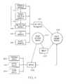
- the packet definition process 402calls artifacts 404 , metrics 406 , and a template 408 to define a work packet.
- the artifactsmay be one or more of: governance artifacts 410 (intellectual assets produced in the software factory by the Software Factory Governance Board 108 described in FIG. 1 ); business contextual artifacts 412 (intellectual assets produced in the software factory by business analysts in the requirement analysis team 114 described in FIG. 1 ); architectural artifacts 414 (intellectual assets produced by the architecture team 116 described in FIG.
- test artifacts 416intelligent assets produced by test architects in the architecture team 116 shown in FIG. 1
- project artifacts 418intelligent assets produced in the software factory by system engineers in the design center 112 shown in FIG. 1 ).
- the metrics 406may be one or more of: governance metrics 420 (measurable governance indicators, such as business plans); factory metrics 422 (measurable indicators that describe the capabilities of the software factory, including assembly line capacity); and system metrics 424 (measurable indicators that describe the capabilities of the client's computer system on which deliverables are to be run).
- governance metrics 420measurable governance indicators, such as business plans
- factory metrics 422measurable indicators that describe the capabilities of the software factory, including assembly line capacity
- system metrics 424measurable indicators that describe the capabilities of the client's computer system on which deliverables are to be run.
- artifacts 404 and metrics 406are used by a packet assembly process 426 to assemble one or more work packets.
- Template 408describes how a work packet is to be assembled.
- the template 408includes metadata references to key artifacts 404 and metrics 406 , which are merged into a formal work packet definition as described above.
- the work packetis then assembled in a standardized hierarchical way and packaged within a factory message envelope that contains a header and body.
- FIG. 5a high-level flow-chart of steps taken to define and assemble work packets is presented.
- initiator block 502which may be an order by the Requirements Analysis Team 114 to the Architecture Team 116 , shown in FIG. 1 , to create a design center-defined work packet
- the requisite packet definitionsare created for work packets that are to be used in deliverables (block 504 ).
- a templatewhich preferably is a reusable that has been used in the past to create the type of work packet needed, is called (block 506 ).
- the needed artifacts (block 508 ) and metrics (block 510 )are called.
- the called artifacts and metricsare assembled in the requisite work packets (block 512 ), and the process ends.
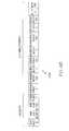
- work packetsare fungible (easily interchangeable and reusable for different deliverables). As such, they are stored in an archival manner. In order to retrieve them efficiently, however, they are categorized, classified, and named. For example, consider the header 600 shown in FIG. 6 a . Header 600 is associated with a specific work packet 602 that includes software code 604 . The name of the work packet is created by the architect who originally created the work packet 602 . Preferably, the name is descriptive of the function of the work packet 602 , such as “Security work packet”, which can be used in the assembly of a security deliverable. The header may describe whether the work packet is proprietary for a particular client, such that the work packet may be reused only for that client. A description (coded, flagged, etc.) for what the work packet is used for may be included, as well as the names of particular components (such as the eight components described above).
- header 606An alternate header for a work packet is shown in FIG. 6 b as header 606 .
- the header 606 for every work packetcontains the first four values shown (“Work Packet ID,” “Work Packet Description,” “Work Packet Type,” and “Parent Packet ID”). That is, each work packet has a unique identification number (“Work Packet ID”), a short description of the work packet (“Work Packet Description”), a description of the type of work packet (“Work Packet Type,” such as “security,” “spreadsheet,” etc.), and the identifier (“Parent Packet ID”) of any parent object from which the work packet has inheritance.
- Work Packet IDa unique identification number
- Work Packet Descriptiona short description of the work packet
- Work Packet Typea description of the type of work packet
- Parent Packet IDsuch as “security,” “spreadsheet,” etc.
- an architectdefines header components for an asset (e.g. a work packet) header (block 704 ).
- these header componentsallow an Asset Repository to perform a metadata categorization search of the assets.
- These header componentsmay be any that the programmer wishes to use, including those shown in exemplary manner in FIGS. 6 a - b .
- the architectpopulates them with descriptors (block 706 ).
- a system manager or softwarearchives (stores) the work packet, including the header (block 708 ).
- a program or programmercan retrieve the work packet by specifying information in the header (block 710 ). For example, if the program or programmer needs a work packet that is of a “Security” type that follows “Standard 100”, then “Work packet one” can be retrieved at “Address 1”, as depicted in FIG. 6 a . Note, however, that this work packet cannot be utilized unless it is to be used in the construction of a deliverable for the client “Toyota.” The process ends at terminator block 712 .
- An exemplary scorecardis as follows:
- all of these stepsare taken before a project is taken on by the Software Factory Governance Board 106 described above in FIG. 1 . These steps ensure the health and capacity of the software factory to create and assemble work packets into a client-ordered deliverable.
- Step 15 of the Factory Readiness Review processsoftware factory on-boarding is a rapid process that uses a series of checklist questionnaires to help with the rapid set-up and configuration of the software factory.
- the software factory on-boarding processis an accelerator process model that enables the roll out configuration of uniquely defined software factor instances. This is a learning process that leverages patterns used in prior on-boarding exercises. This evolution provides a pertinent series of checklist questionnaires to qualify what is necessary for a rapid set-up and confirmation of a factory instance to support a project. Based on project type assessments, installed factory patterns can be leveraged to forecast what is necessary to set up a similar factory operation.
- Rapid on-boardingprovides a calculated line and work cell balancing capability view of leveraged resources, thus improving throughput of assembly lines and work cells while reducing manpower requirements and costs.
- the balancing moduleinstantly calculates the optimum utilization using the fewest operators to achieve the result requested. Parameters can be varied as often as needed to run “what-if” scenarios.
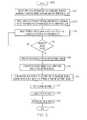
- processes used by a software factoryare determined for a first project (block 804 ). These processes (and perhaps choke-points) lead to a checklist, which describes the processes of the first process (block 806 ). Examples of processes include, but are not limited to, the creation of work packets, testing work packets, etc. Examples of choke-points include, but are not limited to, available computing power and memory i a service computer in which the software factory will run; available manpower; available communication channels; etc.
- the checklistcan be used by the Software Factory Operations 110 (shown in FIG. 1 ) to check processes/choke-points that can be anticipated by the new work project (block 808 ). That is, assume that the first project and the new project are both projects for creating a computer security program.
- a rapid determinationcan be made by a programmer (or automated software) as to whether the software factory is capable of handling the new work project.
- the software factoryis configured (block 812 ) as before (for the first project), and the process ends (terminator block 814 ).
- a “Not Ready”messageis sent back to the Software Factory Operations (such as to the Software Factory Governance Board) (block 816 ), thus ending the process (terminator block 814 ), unless the Software Factory Governance Board elects to retry configuring the software factory (either using the rapid on-board process or the full process described above).
- This induction processprovides an analysis of the proposed software project. The analysis not only identifies what processes and sub-processes will be needed to create the software project, but will also identify potential risks to the software factory and/or the client's computer system.
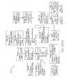
- a candidate project 902is submitted to software factory 100 (preferably to the Software Factory Governance Board 108 shown in FIG. 1 ) as a factory project proposal 904 .
- the factory project proposal 904then goes through a service definition process 906 .
- Service definition process 906utilizes electronic questionnaire checklists 908 to help define a service definition template 910 .
- Checklists 908are a collection of drill down checklists that provide qualifying questions related to the candidate project 902 .
- the questions asked in the checklists 908are based on pre-qualifying questions. That is, as shown in FIG. 10 a , pre-qualification questions 1002 are broad questions that relate to different types of projects. Based on the answers submitted to questions in the pre-qualification questions 1002 , a specific checklist from checklists 908 a - n is selected.
- pre-qualification questions 1002include four questions: 1) Who is the client? 2) Is the project security related? 3) Will the project run on the client's hardware? 4) When is the proposed project due?
- one of the checklists 908will be selected. That is, if the answers for the four questions were 1) Toyota, 2) Yes, 3) Yes and 4) Six months, then a checklist 908 b , which has questions that are heuristically known (from past projects) to contain the most relevant questions for such a project is then automatically selected.
- the selected checklists 908are then used to generate the service definition template 910 , which is essentially a compilation of checklists 908 that are selected in the manner described in FIG. 10 a .
- Service definition template 910is then sent to a Service Assessment Review (SAR) 912 .
- SAR 912is a weighted evaluation process that, based on answers to qualifying, and preferably closed ended (yes/no), questions derived from the service definition template 910 , evaluates the factory project proposal 904 for completeness and preliminary risk assessment.
- SAR 912provides an analysis of relevant areas of what is known (based on answers to questions found in the service definition template 910 ) and what is unknown (could not be determined, either because of missing or unanswered questions in the service definition template 910 ) about the candidate project 902 .
- the outcome of SAR 912is a qualification view (gap analysis) for the factory project proposal 904 , which provides raw data to a scoring and classification process 914 .
- the scoring and classification process 914is a scoring and tabulation of the raw data that is output from SAR 912 . Based on the output from SAR 912 , the scoring and classification process 914 rates the factory project proposal 904 on project definition completeness, trace-ability and risk exposure. If the service definition template 910 indicates that third parties will be used in the candidate project 902 , then the scoring and classification process 914 will evaluate proposed third party providers 932 through the use of a third party required consent process 918 .
- the third party required consent process 918manages relationships between third party providers 932 and the software factory 100 .
- Example of such third party providers 932include, but are not limited to, a third party contractor provider 920 (which will provide software coding services for components of the candidate project 902 ), a third party service provider 922 (which will provide an execution environment for sub-components of the candidate project 902 ), and vendor product support 924 (which provides call-in and/or on-site support for the completed project).
- the determination of whether the third party providers 932 and the software factory 100 can work in partnership on the projectis based on a Yes/No questionnaire that is sent from the software factory 100 to the third party providers 932 .
- the questionnaire that is sent to the third party providers 932includes questions about the third party's financial soundness, experience and capabilities, development and control process (including documentation of work practices), technical assistance that can be provided by the third party (including available enhancements), quality practices (including what type of conventions the third party follows, such as ISO 9001), maintenance service that will be provided, product usage (including a description of any licensing restrictions), costs, contracts used, and product warranty.
- the factory project proposal 904fails this scoring process, it is sent back to a remediation process 916 . However, if scoring process gives an initial indication that the factory project proposal 904 is ready to be sent to the software factory, then it is sent to the service induction process 926 .
- the factory project proposal 904is then inducted (pre-qualified for approval) by the service induction process 926 .
- the service induction process 926the scored and classified project is sent through a Conceptual Requirements Review, which utilizes a service repository scorecard 928 to determine if the software factory 100 is able to handle the candidate project 902 . That is based on the checklists, evaluations, scorecards and classifications depicted in FIG. 9 , the candidate project 902 receives a final evaluation to determine that the software factory 100 has the requisite resources needed to successfully execute the candidate project 902 . If so, then the candidate project becomes a factory project 930 , and a contract agreement is made between the client and the service provider who owns the software factory 100 .
- the Software Factory Meta-Morphic Dynamic Restructuring Logic Tree Modelqualifies answers to checklist questions to determine if a next checklist is relevant to what is needed to determine what type of work packets are needed for the client's project. This expedites the data collection and analysis process, and thus provides a scalable flexibility to data collection and logic decision tree processing and constructions.
- a software diagram 1004shows a relationship between different software objects used to dynamically generate checklists used to determine what work packets are needed to create a deliverable.
- Objects 1005 a - dare used to track and receive answers to a particular checklist, while objects 1007 a - c are used to evaluate each checklist to determine if it is relevant to the inquiry needed for determining what work packets are needed for a project related to a particular checklist category.
- FIG. 10 ca Software Factory Packet Pattern Analysis and Predictive Forecasting Model 1006 , which is an excerpt of a Software Factory data model, shows the relational pattern between areas of pattern analysis.
- FIG. 10 dshows a pattern 1012 of relationships between different assets, project types, templates, schema, tasks and processes. These relationships are a by-product of the Software Factory Packet Pattern Analysis and Predictive Forecasting Model 1006 shown in FIG. 10 c.
- FIG. 10 ea high-level flow-chart of steps taken to dynamically manage checklists used to select appropriate work packets in a software factory is presented in FIG. 10 e .
- initiator block 1014which may be prompted by a client requesting a deliverable from the software factory
- an initial checklistis presented (block 1016 ).
- This checklistconsists of a series of question groups, which are categorized according to a particular type of deliverable. For example, a security software program may be associated with a particular checklist category for “security software.”
- answers to the first group of questionsare received by the Software Factory Packet Pattern Analysis and Predictive Forecasting Model 1006 shown in FIG. 10 c .
- a dynamically generated new checklistis created (block 1022 ). Note that this new checklist is not merely an existing node in a decision tree. Rather, based on received answers, a new checklist is dynamically created using stored questions that are tagged and associated with a particular set of answers. Thus, if a set of two questions resulted in respective answers “True” and “False”, this would results in a different set of next questions than what would be generated if the respective answers were “True” and “True” (or any other combination of answers other than “True” and “False”).
- answers to the new checklistare evaluated based on their contextual reference and the nature of the questioning objectives. That is, based on what question parameters are used for the work packets being generated, a determination can be made as to whether additional new checklists need to be constructed (query block 1026 ). If so, then the process returns to block 1022 in an iterative manner. If not, then the process ends (terminator block 1028 ), indicating that the checklist process for determining what qualities are needed in the work packets has concluded.
- leading indicatorcan influence how answers are evaluated.
- leading indicatorsinclude descriptors of the final deliverable that will be generated by the software factory, a client's name or field, etc. As leading indicators change, they can change content relevance and perspective reference points and drive the restructuring of relevant questions that can be restructured along that leading indicator relative perspective.
- the software factory described hereinshould be monitored for a variety of issues. Such monitoring is performed by a Software Factory Analytics and Dashboard, which ensures that both a single instance and multiple instances of the Factory can function smoothly.
- the monitored metricsinclude project metrics as well as factory operations, system, business, and performance activities.
- the analytics of the overall health of the factorycan be audited and monitored and used as a basis for continual process improvement strategic analysis and planning. This ensures fungibility and consistency, provides quality assurance, reduces the risk of failure, and increases cost effectiveness.
- An ESBprovides a standard-based integration platform that combines messaging, web services, data transformation and intelligent routing in an event driven Service Oriented Architecture (SOA).
- SOAService Oriented Architecture
- applications and servicesare treated as abstract endpoints, which can readily respond to asynchronous events.
- the SOAprovides an abstraction away from the details of the underlying connectivity and plumbing.
- the implementations of the servicesdo not need to understand protocols. Services do not need to know how messages are routed to other services. They simply receive a message from the ESB as an event, and process the message.
- Process flow in an ESBcan also involve specialized integration services that perform intelligent routing of messages based on content. Because the process flow is built on top on of the distributed SOA, it is also capable of spanning highly distributed deployment topologies between services on the bus.
- the messages that flow on the ESBcontain measurable metrics and states that are received through an event driven Service Oriented Architecture (SOA) Model.
- SOAService Oriented Architecture
- This informationis via XML data stream messages, which can contain factory operation, system, business and performance and activity related metrics, which provide a relative point of origin for low level measurement.
- the messagescan be used in analytics of the factory's overall health, which is audited and monitored, and can be used as a basis for continual process improvement strategic analysis and planning.
- the data streamis analyzed and the aggregated Key Performance Indicators (KPIs) are calculated and sent to the dashboard display device, where the XML is applied to a style template and rendered for display.
- KPIsKey Performance Indicators
- the Health Monitoring Systemprovides factory exception and error reporting, system monitoring, Performance Monitoring and Reporting, Proactive and Reactive Alert Notification, Message Auditing and Tracking Reporting, Daily View of Activity, and Historical Reports. Information collected includes what information (regarding the software factory metrics) was sent, to whom it was sent, when it was sent, and how many messages were sent via the ESB interface between the software factory and the client's system.
- Information in the messagesincludes timestamps for the sender (from the software factory), the receiver (in the analytic section), and the hub (the ESB).
- Derived metricsinclude:
- Service endpoint 1102 aprovides analytic service for measurements taken in the software factor 100 .
- Service endpoint 1102 bprovides an audit service, which determines which analytic measurements should be taken.
- Service endpoint 1102 cprovides a web service that affords analytic measurements and dashboards to be transmitted in HTML or other web-based format to a monitor.
- a service endpointincludes the application (service software) 1104 , an application interface 1106 , a resource adapter 1108 , a managed connection 1110 , a client interface 1112 , an ESB endpoint 1114 , an invocation and management framework 1116 (protocol stacks that can be sued for transporting messages across an ESB), and a service container 1118 (an operating system process that can be managed by the invocation and management framework 1116 ).
- applicationservice software
- an application interface 1106includes the application interface 1106 , an application interface 1106 , a resource adapter 1108 , a managed connection 1110 , a client interface 1112 , an ESB endpoint 1114 , an invocation and management framework 1116 (protocol stacks that can be sued for transporting messages across an ESB), and a service container 1118 (an operating system process that can be managed by the invocation and management framework 1116 ).
- Each service endpoint 1102is coupled to the Enterprise Service Bus (ESB) 1120 , to which XML message 1122 (or similar markup language formatted messages) can flow to governance monitors 1124 , factory operations monitors 1126 and/or system engineering monitors 1128 , on which the messages generate dashboard progress messages.
- ESDEnterprise Service Bus
- FIG. 12a flow-chart of exemplary steps taken to monitor the health of a software factory is presented.
- initiator block 1202which may be prompted by the acceptance of a work project as described above
- work packetsare first defined (block 1204 ). As described above, these work packets are then sent to the assembly area. This transmittal is tracked (block 1206 ) by sending a message 1122 to the ESB 1120 shown in FIG. 11 . This message 1122 contains information about where and when the work packet was sent to the assembly line. If the work packet pulls an artifact (such as artifacts 404 described in FIG. 4 ), another message is sent to the ESB for tracking purposes (block 1208 ).
- an artifactsuch as artifacts 404 described in FIG. 4
- messagesare sent to the ESB if there are any on-going changes of work activities contained in the work packets (block 1210 ).
- Execution of the work packetsis monitored to ensure that such execution conforms with governance guidelines that have been previously set for the software factory (block 1212 ).
- the software factoryis monitored to ensure that work packets comply with the architecture of the software factory (block 1214 ).
- Quality metricsare also monitored for the execution of the work packets in the assembly line area (block 1216 ). That is, as different work packets are executed, assembled and tested in the assembly line area, the quality of such operations is tracked. These metrics include, but are not limited to, those described above, plus completion rates, detection of software defects, hazards (risks) caused by the execution of the work packets and other issues.
- This information(and optionally any other information monitored and tracked in block 1206 to 1214 ) is sent on the ESB to a dashboard in a monitoring display, as described in FIG. 11 above.
- FIG. 13there is depicted a block diagram of an exemplary client computer 1302 , in which the present invention may be utilized. Note that some or all of the exemplary architecture shown for client computer 1302 may be utilized by software deploying server 1350 , as well as monitors 1124 , 1126 and 1128 shown in FIG. 11 .
- Client computer 1302includes a processor unit 1304 that is coupled to a system bus 1306 .
- a video adapter 1308which drives/supports a display 1310 , is also coupled to system bus 1306 .
- System bus 1306is coupled via a bus bridge 1312 to an Input/Output (I/O) bus 1314 .
- An I/O interface 1316is coupled to PO bus 1314 .
- I/O interface 1316affords communication with various PO devices, including a keyboard 1318 , a mouse 1320 , a Compact Disk-Read Only Memory (CD-ROM) drive 1322 , a floppy disk drive 1324 , and a flash drive memory 1326 .
- the format of the ports connected to I/O interface 1316may be any known to those skilled in the art of computer architecture, including but not limited to Universal Serial Bus (USB) ports.
- USBUniversal Serial Bus
- Client computer 1302is able to communicate with a software deploying server 1350 via a network 1328 using a network interface 1330 , which is coupled to system bus 1306 .
- Network interface 1330may include an Enterprise Service Bus (not shown), such as ESB 1120 shown in FIG. 11 .
- Network 1328may be an external network such as the Internet, or an internal network such as an Ethernet or a Virtual Private Network (VPN).
- VPNVirtual Private Network
- the software deploying server 1350may utilize a same or substantially similar architecture as client computer 1302 .
- a hard drive interface 1332is also coupled to system bus 1306 .
- Hard drive interface 1332interfaces with a hard drive 1334 .
- hard drive 1334populates a system memory 1336 , which is also coupled to system bus 1306 .
- System memoryis defined as a lowest level of volatile memory in client computer 1302 . This volatile memory includes additional higher levels of volatile memory (not shown), including, but not limited to, cache memory, registers and buffers.
- Data that populates system memory 1336includes client computer 1302 's operating system (OS) 1338 and application programs 1344 .
- OSoperating system
- OS 1338includes a shell 1340 , for providing transparent user access to resources such as application programs 1344 .
- shell 1340is a program that provides an interpreter and an interface between the user and the operating system. More specifically, shell 1340 executes commands that are entered into a command line user interface or from a file.
- shell 1340(as it is called in UNIX®), also called a command processor in Windows®, is generally the highest level of the operating system software hierarchy and serves as a command interpreter.
- the shellprovides a system prompt, interprets commands entered by keyboard, mouse, or other user input media, and sends the interpreted command(s) to the appropriate lower levels of the operating system (e.g., a kernel 1342 ) for processing.
- a kernel 1342the appropriate lower levels of the operating system for processing.
- shell 1340is a text-based, line-oriented user interface
- the present inventionwill equally well support other user interface modes, such as graphical, voice, gestural, etc.
- OS 1338also includes kernel 1342 , which includes lower levels of functionality for OS 1338 , including providing essential services required by other parts of OS 1338 and application programs 1344 , including memory management, process and task management, disk management, and mouse and keyboard management.
- kernel 1342includes lower levels of functionality for OS 1338 , including providing essential services required by other parts of OS 1338 and application programs 1344 , including memory management, process and task management, disk management, and mouse and keyboard management.
- Application programs 1344include a browser 1346 .
- Browser 1346includes program modules and instructions enabling a World Wide Web (WWW) client (i.e., client computer 1302 ) to send and receive network messages to the Internet using HyperText Transfer Protocol (HTTP) messaging, thus enabling communication with software deploying server 1350 .
- WWWWorld Wide Web
- HTTPHyperText Transfer Protocol
- Application programs 1344 in client computer 1302 's system memoryalso include a Software Factory Program (SFP) 1348 .
- SFP 1348includes code for implementing the processes described in FIGS. 1-12 and 14 a - 15 b .
- client computer 1302is able to download SFP 1348 from software deploying server 1350 .
- client computer 1302may include alternate memory storage devices such as magnetic cassettes, Digital Versatile Disks (DVDs), Bernoulli cartridges, and the like. These and other variations are intended to be within the spirit and scope of the present invention.
- DVDsDigital Versatile Disks
- software deploying server 1350performs all of the functions associated with the present invention (including execution of SFP 1348 ), thus freeing client computer 1302 from having to use its own internal computing resources to execute SFP 1348 .
- the present inventionmay alternatively be implemented in a computer-readable medium that contains a program product.
- Programs defining functions of the present inventioncan be delivered to a data storage system or a computer system via a variety of tangible signal-bearing media, which include, without limitation, non-writable storage media (e.g., CD-ROM), writable storage media (e.g., hard disk drive, read/write CD ROM, optical media), as well as non-tangible communication media, such as computer and telephone networks including Ethernet, the Internet, wireless networks, and like network systems.
- non-writable storage mediae.g., CD-ROM
- writable storage mediae.g., hard disk drive, read/write CD ROM, optical media
- non-tangible communication mediasuch as computer and telephone networks including Ethernet, the Internet, wireless networks, and like network systems.
- the processes described by the present inventionare performed by service provider server 1350 .
- SFP 1348 and the method described herein, and in particular as shown and described in FIGS. 1-12can be deployed as a process software from service provider server 1350 to client computer 1302 .
- process software for the method so describedmay be deployed to service provider server 1350 by another service provider server (not shown).
- step 1400begins the deployment of the process software.
- the first thingis to determine if there are any programs that will reside on a server or servers when the process software is executed (query block 1402 ). If this is the case, then the servers that will contain the executables are identified (block 1404 ).
- the process software for the server or serversis transferred directly to the servers' storage via File Transfer Protocol (FTP) or some other protocol or by copying though the use of a shared file system (block 1406 ).
- FTPFile Transfer Protocol
- the process softwareis then installed on the servers (block 1408 ).
- a proxy serveris a server that sits between a client application, such as a Web browser, and a real server. It intercepts all requests to the real server to see if it can fulfill the requests itself. If not, it forwards the request to the real server. The two primary benefits of a proxy server are to improve performance and to filter requests. If a proxy server is required, then the proxy server is installed (block 1416 ). The process software is sent to the servers either via a protocol such as FTP or it is copied directly from the source files to the server files via file sharing (block 1418 ).
- Another embodimentwould be to send a transaction to the servers that contained the process software and have the server process the transaction, then receive and copy the process software to the server's file system. Once the process software is stored at the servers, the users, via their client computers, then access the process software on the servers and copy to their client computers file systems (block 1420 ). Another embodiment is to have the servers automatically copy the process software to each client and then run the installation program for the process software at each client computer. The user executes the program that installs the process software on his client computer (block 1422 ) then exits the process (terminator block 1424 ).
- the set of users where the process software will be deployedare identified together with the addresses of the user client computers (block 1428 ).
- the process softwareis sent via e-mail to each of the users' client computers (block 1430 ).
- the usersthen receive the e-mail (block 1432 ) and then detach the process software from the e-mail to a directory on their client computers (block 1434 ).
- the userexecutes the program that installs the process software on his client computer (block 1422 ) then exits the process (terminator block 1424 ).
- process softwareis sent directly to user directories on their client computers (query block 1436 ). If so, the user directories are identified (block 1438 ).
- the process softwareis transferred directly to the user's client computer directory (block 1440 ). This can be done in several ways such as but not limited to sharing of the file system directories and then copying from the sender's file system to the recipient user's file system or alternatively using a transfer protocol such as File Transfer Protocol (FTP).
- FTPFile Transfer Protocol
- the usersaccess the directories on their client file systems in preparation for installing the process software (block 1442 ).
- the userexecutes the program that installs the process software on his client computer (block 1422 ) and then exits the process (terminator block 1424 ).
- the present softwarecan be deployed to third parties as part of a service wherein a third party VPN service is offered as a secure deployment vehicle or wherein a VPN is build on-demand as required for a specific deployment.
- a virtual private networkis any combination of technologies that can be used to secure a connection through an otherwise unsecured or untrusted network.
- VPNsimprove security and reduce operational costs.
- the VPNmakes use of a public network, usually the Internet, to connect remote sites or users together. Instead of using a dedicated, real-world connection such as leased line, the VPN uses “virtual” connections routed through the Internet from the company's private network to the remote site or employee.
- Access to the software via a VPNcan be provided as a service by specifically constructing the VPN for purposes of delivery or execution of the process software (i.e. the software resides elsewhere) wherein the lifetime of the VPN is limited to a given period of time or a given number of deployments based on an amount paid.
- the process softwaremay be deployed, accessed and executed through either a remote-access or a site-to-site VPN.
- the process softwareWhen using the remote-access VPNs the process software is deployed, accessed and executed via the secure, encrypted connections between a company's private network and remote users through a third-party service provider.
- the enterprise service provider (ESP)sets a network access server (NAS) and provides the remote users with desktop client software for their computers.
- the telecommuterscan then dial a toll-free number or attach directly via a cable or DSL modem to reach the NAS and use their VPN client software to access the corporate network and to access, download and execute the process software.
- the process softwareWhen using the site-to-site VPN, the process software is deployed, accessed and executed through the use of dedicated equipment and large-scale encryption that are used to connect a company's multiple fixed sites over a public network such as the Internet.
- the process softwareis transported over the VPN via tunneling which is the process of placing an entire packet within another packet and sending it over a network.
- tunnelingis the process of placing an entire packet within another packet and sending it over a network.
- the protocol of the outer packetis understood by the network and both points, called tunnel interfaces, where the packet enters and exits the network.
- the process softwarewhich consists of code for implementing the process described herein may be integrated into a client, server and network environment by providing for the process software to coexist with applications, operating systems and network operating systems software and then installing the process software on the clients and servers in the environment where the process software will function.
- the first stepis to identify any software on the clients and servers, including the network operating system where the process software will be deployed, that are required by the process software or that work in conjunction with the process software.
- the software applications and version numberswill be identified and compared to the list of software applications and version numbers that have been tested to work with the process software. Those software applications that are missing or that do not match the correct version will be upgraded with the correct version numbers.
- Program instructions that pass parameters from the process software to the software applicationswill be checked to ensure the parameter lists match the parameter lists required by the process software.
- parameters passed by the software applications to the process softwarewill be checked to ensure the parameters match the parameters required by the process software.
- the client and server operating systems including the network operating systemswill be identified and compared to the list of operating systems, version numbers and network software that have been tested to work with the process software. Those operating systems, version numbers and network software that do not match the list of tested operating systems and version numbers will be upgraded on the clients and servers to the required level.
- the integrationis completed by installing the process software on the clients and servers.
- the process softwareis shared, simultaneously serving multiple customers in a flexible, automated fashion. It is standardized, requiring little customization and it is scalable, providing capacity on demand in a pay-as-you-go model.
- the process softwarecan be stored on a shared file system accessible from one or more servers.
- the process softwareis executed via transactions that contain data and server processing requests that use CPU units on the accessed server.
- CPU unitsare units of time such as minutes, seconds, hours on the central processor of the server. Additionally the accessed server may make requests of other servers that require CPU units.
- CPU unitsdescribe an example that represents but one measurement of use. Other measurements of use include but are not limited to network bandwidth, memory utilization, storage utilization, packet transfers, complete transactions etc.
- the measurements of use used for each service and customerare sent to a collecting server that sums the measurements of use for each customer for each service that was processed anywhere in the network of servers that provide the shared execution of the process software.
- the summed measurements of use unitsare periodically multiplied by unit costs and the resulting total process software application service costs are alternatively sent to the customer and/or indicated on a web site accessed by the customer which then remits payment to the service provider.
- the service providerrequests payment directly from a customer account at a banking or financial institution.
- the payment owed to the service provideris reconciled to the payment owed by the service provider to minimize the transfer of payments.
- initiator block 1502begins the On Demand process.
- a transactionis created than contains the unique customer identification, the requested service type and any service parameters that further, specify the type of service (block 1504 ).
- the transactionis then sent to the main server (block 1506 ).
- the main servercan initially be the only server, then as capacity is consumed other servers are added to the On Demand environment.
- the server central processing unit (CPU) capacities in the On Demand environmentare queried (block 1508 ).
- the CPU requirement of the transactionis estimated, then the server's available CPU capacity in the On Demand environment are compared to the transaction CPU requirement to see if there is sufficient CPU available capacity in any server to process the transaction (query block 1510 ). If there is not sufficient server CPU available capacity, then additional server CPU capacity is allocated to process the transaction (block 1512 ). If there was already sufficient available CPU capacity then the transaction is sent to a selected server (block 1514 ).
- On Demand environmentBefore executing the transaction, a check is made of the remaining On Demand environment to determine if the environment has sufficient available capacity for processing the transaction. This environment capacity consists of such things as but not limited to network bandwidth, processor memory, storage etc. (block 1516 ). If there is not sufficient available capacity, then capacity will be added to the On Demand environment (block 1518 ). Next the required software to process the transaction is accessed, loaded into memory, then the transaction is executed (block 1520 ).
- the usage measurementsare recorded (block 1522 ).
- the utilization measurementsconsist of the portions of those functions in the On Demand environment that are used to process the transaction.
- the usage of such functions as, but not limited to, network bandwidth, processor memory, storage and CPU cyclesare what is recorded.
- the usage measurementsare summed, multiplied by unit costs and then recorded as a charge to the requesting customer (block 1524 ).
- On Demand costsare posted to a web site (query block 1526 ). If the customer has requested that the On Demand costs be sent via e-mail to a customer address (query block 1530 ), then these costs are sent to the customer (block 1532 ). If the customer has requested that the On Demand costs be paid directly from a customer account (query block 1534 ), then payment is received directly from the customer account (block 1536 ). The On Demand process is then exited at terminator block 1538 .
- the present inventionprovides a computer-implemented method, system, and computer-readable medium for determining if a software factory is ready to take on a software project.
- the computer-implemented methodincludes the steps of: determining if an infrastructure for a software factory has been procured; determining if operational software needed to assemble work packets in an assembly line in the software factory has been installed; determining if a workflow event model for an assembly line in the software factory has been configured; determining if workload in the assembly line has been balanced; determining if communication channels between the software factory and a customer's computer system have been defined and cleared for data transmission; and in response to determining that any element described above has been determined not to have occurred, prohibiting an induction of a software project into the software factory.
- these stepsare performed in a software factory, which includes the components of a software factory governance section that evaluates the project proposal for acceptance by the software factory; a design center composed of a requirements analysis team and an architecture team, wherein the design center sections the project proposal into major functional areas that are to be handled by the requirements analysis team and the architecture team, and wherein the design center creates the work packets; and an assembly line that receives and executes the work packets to create the deliverable custom software.
- the design centerincludes: a requirements analysis team, wherein the requirements analysis team is responsible for determining system requirements for executing the deliverable custom software on the customer's system; and an architectural team, wherein the architectural team models the project proposal in accordance with customer constraints, and wherein the architectural team bundles the customer constraints together with the work packets for execution in the assembly line.
- the work packetsinclude governance procedures, standards, reused assets, work packet instructions, integration strategy, schedules, exit criteria and artifact checklist templates for Input/Output routines.
- the assembly line in the software factorymay include software that automatically recognizes a project type for the project proposal, and wherein the assembly line assembles the work packets into the deliverable custom software in accordance with the project type that is recognized by the assembly line.
- the assembly lineconducts an integration test, a system test, a system integration test and a performance test of the deliverable custom software, wherein the integration test tests the deliverable custom software for compatibility with the client's system, the system test checks the client's system to ensure that the client's system is operating properly, the system integration test tests for bugs that may arise when the deliverable custom software is integrated into the client's system, and the performance test tests the deliverable custom software for defects as it is executing in the client's system.
- the assembly lineincludes a published set of services and a published set of requirements for the assembly line, wherein the published set of services and the published set of requirements for the assembly line are published to the design center, and wherein the published set of services describes what assembly services for assembling work packets are offered by the assembly line, and wherein the published set of requirements describes what execution environment must be used by work packets that are provided by the design center for assembly in the assembly line.
- the term “computer” or “system” or “computer system” or “computing device”includes any data processing system including, but not limited to, personal computers, servers, workstations, network computers, main frame computers, routers, switches, Personal Digital Assistants (PDA's), telephones, and any other system capable of processing, transmitting, receiving, capturing and/or storing data.
- PDAPersonal Digital Assistants
Landscapes
- Business, Economics & Management (AREA)
- Engineering & Computer Science (AREA)
- Economics (AREA)
- Entrepreneurship & Innovation (AREA)
- Human Resources & Organizations (AREA)
- Marketing (AREA)
- Operations Research (AREA)
- Quality & Reliability (AREA)
- Strategic Management (AREA)
- Tourism & Hospitality (AREA)
- Physics & Mathematics (AREA)
- General Business, Economics & Management (AREA)
- General Physics & Mathematics (AREA)
- Theoretical Computer Science (AREA)
- Management, Administration, Business Operations System, And Electronic Commerce (AREA)
Abstract
Description
| [Work Packet Definition - Stored in Asset Repository] |
| <Factory Envelope ClientCode = 999, Version =1.0 , |
| FactoryInstanceID = 012, ProjectID=1001> |
| <Header> |
| ..... |
| ..... |
| ..... |
| ...... |
| </Header> |
| <Body> |
| <Asset ID> |
| <Asset Type> |
| <Project Type> |
| <Work Packet ID = ####,CreationDate =011007, Source = DC100> |
| <Work Packet Description> |
| <Work Packet Type [1–90]> |
| <Parent Packet ID = ####> |
| <Governance> |
| <Governance_Artifact ID = #### Type = 1 [Policy,Procedure,]> |
| <Governance_Artifact ID .....> |
| <Governance_Artifact ID ....> |
| <Governance_Artifact ID ....> |
| </Governance> |
| <Business> |
| <Business_Artifact ID = ### Type = 2 [1=Success Factor, 2=Use Case, |
| 3=Business Context, 4= NFR, etc> |
| <Business_Artifact ID = ### Type = 2> |
| <Business_Artifact ID = ### Type = 2> |
| <Business_Artifact ID = ### Type = 2> |
| </Business> |
| <Architecture Artifact ID Type = 3 [ 1= Information, 2=Data, |
| 3=Application,4=Integration, 5=Security, 6=System, 7=Test, etc.]> |
| <Architecture_Artifiact ID > |
| <Architecture_Artifiact ID > |
| <Architecture_Artifiact ID > |
| <Architecture_Artifiact ID > |
| <Architecture_Artifiact ID> |
| <Architecture_Artifiact ID> |
| <Architecture_Artifiact ID> |
| <Architecture_Artifact ID> |
| </Architecture> |
| <Project ID = xxx> |
| <Project Artifact ID = ####> |
| <Project Artifacts> |
| <Project Metrics> |
| </Project> |
| </Work Packet> |
| </Body> |
| </Factory Envelope> |
- 1. Factory Resource Plan (Business and IT Environment) completed
- 2. Infrastructure (Hardware, Network) procurement complete
- 3. Operational Software installed
- 4. Integrated Tools installed
- a. Design Center
- i. Requirement Management,
- ii. Business Modeling
- iii. Architectural Modeling
- iv. Test Management
- v. Configuration (Release) Management
- vi. Change Management
- b. Execution Units
- i. IDE (Integrated Development Environment)
- a. Design Center
- 5. Automate information handled (Service Oriented Architecture (SOA)—reusable model for Factory Installations)
- 6. Process, equipment and product data integrated and statistically analyzed
- 7. Enterprise Service Bus installed
- a. Common Services
- i. Audit (DB)
- ii. Business Transaction Monitoring
- iii. Performance Monitoring
- iv. System Monitoring
- v. Message Translation/Transformation
- vi. Analysis (Data Analytics)
- vii. Packet Assembly
- viii. Session Mgt
- ix. Security Model Configuration
- x. Process Server Configuration
- xi. Communication Protocol Bridges
- b. Resource Mgt
- c. Asset Mgt
- d. Portal Server
- e. Factory Induction Server
- f. Message Oriented Middleware
- i. Hub
- ii. Router (DB)
- iii. Persistent and Durable Queues (Databases)
- g. Service Activators (Shared Components)
- a. Common Services
- 8. Workflow Engine installed
- 9. Workflow Event Model configured
- 10. Problem-solving organization (internal factory operations (infrastructure) maintenance developed
- 11. Operational Support (System, Open Communication Channel, Defined and Enforced Process and Procedures) hosted
- 12. Project Management Plan in place
- 13. Project Scheduled
- 14. Factory Activity scheduled
- 15. On-boarding—Setup and configuration
- 16. Ongoing capacity planned
- 17. Execution Units (Assembly Line) Balanced
- 18. Human Resources Planned
- a. Reduce the division of labor
- b. Secure the requisite talent
- 19. Factory process implemented to make factory mistake-proof (continued process improvement)
- 20. Introductions and assembly of new process technology managed
- 21. In-line assembly inspected (done via Reviews)
- 22. Factory induction process in place
- 23. Communication channels cleared and defined
- a. Auto-recipe (configuration) download
- i. Populate Activities/Task into workflow
- ii. Configure Message Router
- iii. Configure (queues) communication channels per governance model
- iv. Set up logistics (assess, connectivity) internal maintenance team support (location)
- v. Fast ramp new production processes
- vi. Configure Security model
- 1. User accounts
- 2. Roles and privileges
- a. Network Access
- b. OS File Directory
- c. Database
- vii. Configure Event Model
- viii. Configure Infrastructure Servers
- ix. Distribute Network Logistics
- b. Resource Allocation (including human resources available)
- a. Auto-recipe (configuration) download
- Re-factoring
- Redesign
- Quality Analysis Improvement
- Detail Review
- Review of Error Strategy
What Requestor and Provider are Most Active? - Quantitative Analysis
- Forecast Trends and Budgeting
- Strategic Analysis and Planning
- Market Analysis and Planning
How Long It Took to Process - Resource Realignment
- Capacity Planning
What Requestor and Provider are Least Active? - Optimization and Re-factoring
- Redesign
- Realignment of Strategic and Marketing Planning
- Capacity Planning Realignment
- Compliance—reporting responsibility, procedural and policy execution,
- Continual Process Improvement
- Comparative analysis against baseline and performance objectives.
- Factory Contractual Analysis
- Financial—Profitability
- Increase Revenue
- Lower Costs
- Asset Type Creation Analysis per project type
- When (date/time) Work Packets Definitions are created by project
- Work Packet creation Rate
- Work Packet to Project Type Pattern Analysis
- Design Compliance (Execution Units), Asset/Artifact Reuse
- Design Solution Pattern Analysis per Work Packet Type
Asset Management—Metrics - Asset Repository Growth Rate
- Asset Repository Mix
- Asset Reuse Rate
- Project Asset Usage Patterns
Project—Metrics - Project Proposal Induction Attempt/Success Ratio
- Factory Project Client/Industry Analysis
- Resource Availability Activity and Tasks Status
- Milestone Achievement Rate/Status
- Schedule Analysis
- Budget/Cost Analysis
- Risk Identification
- Issue Tracking
- Defect Tracking Resolution, Project Asset Usage Patterns
- Intelligent Forecaster
Factory Operations—Metrics - Approved Project Pipeline
- Project Throughput Rate Analysis
- Informational Analysis
- Work Packet Distribution Analysis
- Capacity Planning (Forecast/Logistics/Availability)
- Resource Inventory Levels
- Factory Utilization Rate
- Workload Characterization
- Transactional Analysis
- Performance Analysis Distribution
- Traffic Analysis
- Equipment and facilities
- Headcount and human resources data applied to physical resources
- Worker Turnover Rate
- Labor Analysis (hours, overtime, per type of factory worker)
- Process technologies used
- Production volumes
- Factory Operation Trouble Ticket/Problem Resolution (e.g. internal factory operations (infrastructure) maintenance)
- Revenue per project
- Operational Costs per Project
- Fixed
- Variable
- Profit per Project
- Profit per Project Type
System Engineering Analysis - System Engineering—Project Risks
- System Engineering—Software Defects
- System Engineering—Issue Tracking and Resolution
- SEAT Review Scorecards Results
- CRR—Conceptual Requirements Review
- BRR—Business Requirements Review
- SRR—System Requirements Review
- PDR—Preliminary Design Review
- CDR—Critical Design Review
- TRR—Test Readiness Review
- PRR—Production Readiness Review
- FRR—Factory Readiness Review
- Quality Assurance Cause Effect Correlation Analysis
Execution Units—Metrics - Work Packet Consumption Rate
- Start (date/time) Work Packet Execution
- Finish (date/time) Work Packet Execution
- # Cross Trained Execution Unit Workers
- Availability Rate
- Quality Rating per Worker
Claims (17)
Priority Applications (2)
| Application Number | Priority Date | Filing Date | Title |
|---|---|---|---|
| US11/735,152US8296719B2 (en) | 2007-04-13 | 2007-04-13 | Software factory readiness review |
| US13/618,744US8898619B2 (en) | 2007-04-13 | 2012-09-14 | Software factory readiness review |
Applications Claiming Priority (1)
| Application Number | Priority Date | Filing Date | Title |
|---|---|---|---|
| US11/735,152US8296719B2 (en) | 2007-04-13 | 2007-04-13 | Software factory readiness review |
Related Child Applications (1)
| Application Number | Title | Priority Date | Filing Date |
|---|---|---|---|
| US13/618,744ContinuationUS8898619B2 (en) | 2007-04-13 | 2012-09-14 | Software factory readiness review |
Publications (2)
| Publication Number | Publication Date |
|---|---|
| US20080255693A1 US20080255693A1 (en) | 2008-10-16 |
| US8296719B2true US8296719B2 (en) | 2012-10-23 |
Family
ID=39854477
Family Applications (2)
| Application Number | Title | Priority Date | Filing Date |
|---|---|---|---|
| US11/735,152Expired - Fee RelatedUS8296719B2 (en) | 2007-04-13 | 2007-04-13 | Software factory readiness review |
| US13/618,744Expired - Fee RelatedUS8898619B2 (en) | 2007-04-13 | 2012-09-14 | Software factory readiness review |
Family Applications After (1)
| Application Number | Title | Priority Date | Filing Date |
|---|---|---|---|
| US13/618,744Expired - Fee RelatedUS8898619B2 (en) | 2007-04-13 | 2012-09-14 | Software factory readiness review |
Country Status (1)
| Country | Link |
|---|---|
| US (2) | US8296719B2 (en) |
Cited By (7)
| Publication number | Priority date | Publication date | Assignee | Title |
|---|---|---|---|---|
| US9305279B1 (en)* | 2014-11-06 | 2016-04-05 | Semmle Limited | Ranking source code developers |
| US9436446B1 (en)* | 2015-11-16 | 2016-09-06 | International Business Machines Corporation | System for automating calculation of a comprehensibility score for a software program |
| US20160274995A1 (en)* | 2015-03-18 | 2016-09-22 | New Iron Systems, Inc. | Diagnostic Tool and Method for Efficient Software Development |
| US20170220340A1 (en)* | 2014-08-06 | 2017-08-03 | Nec Corporation | Information-processing system, project risk detection method and recording medium |
| US20180081679A1 (en)* | 2013-06-07 | 2018-03-22 | Capital One Financial Corporation | Systems and methods for providing predictive quality analysis |
| US10241786B2 (en)* | 2017-01-26 | 2019-03-26 | International Business Machines Corporation | Evaluating project maturity from data sources |
| US11340870B2 (en)* | 2013-03-14 | 2022-05-24 | Microsoft Technology Licensing, Llc | Software release workflow management |
Families Citing this family (43)
| Publication number | Priority date | Publication date | Assignee | Title |
|---|---|---|---|---|
| US8141040B2 (en)* | 2007-04-13 | 2012-03-20 | International Business Machines Corporation | Assembling work packets within a software factory |
| US8359566B2 (en)* | 2007-04-13 | 2013-01-22 | International Business Machines Corporation | Software factory |
| US8327318B2 (en)* | 2007-04-13 | 2012-12-04 | International Business Machines Corporation | Software factory health monitoring |
| US8464205B2 (en)* | 2007-04-13 | 2013-06-11 | International Business Machines Corporation | Life cycle of a work packet in a software factory |
| US8566777B2 (en)* | 2007-04-13 | 2013-10-22 | International Business Machines Corporation | Work packet forecasting in a software factory |
| US20080256390A1 (en)* | 2007-04-13 | 2008-10-16 | Chaar Jarir K | Project Induction in a Software Factory |
| US8141030B2 (en)* | 2007-08-07 | 2012-03-20 | International Business Machines Corporation | Dynamic routing and load balancing packet distribution with a software factory |
| US8332807B2 (en)* | 2007-08-10 | 2012-12-11 | International Business Machines Corporation | Waste determinants identification and elimination process model within a software factory operating environment |
| US9189757B2 (en)* | 2007-08-23 | 2015-11-17 | International Business Machines Corporation | Monitoring and maintaining balance of factory quality attributes within a software factory environment |
| US8539437B2 (en)* | 2007-08-30 | 2013-09-17 | International Business Machines Corporation | Security process model for tasks within a software factory |
| US7730005B2 (en)* | 2007-12-28 | 2010-06-01 | International Business Machines Corporation | Issue tracking system using a criteria rating matrix and workflow notification |
| US20090262722A1 (en)* | 2008-04-21 | 2009-10-22 | Honeywell International Inc. | Method to Calculate Transitive Closure of Multi-Path Directed Network Based on Declarative MetaData |
| US8452629B2 (en) | 2008-07-15 | 2013-05-28 | International Business Machines Corporation | Work packet enabled active project schedule maintenance |
| US8165912B2 (en)* | 2008-07-16 | 2012-04-24 | Ciena Corporation | Methods and systems for portfolio investment thesis based on application life cycles |
| US8336026B2 (en) | 2008-07-31 | 2012-12-18 | International Business Machines Corporation | Supporting a work packet request with a specifically tailored IDE |
| US8271949B2 (en) | 2008-07-31 | 2012-09-18 | International Business Machines Corporation | Self-healing factory processes in a software factory |
| US7895280B2 (en)* | 2008-09-03 | 2011-02-22 | Microsoft Corporation | Composing message processing pipelines |
| US8495583B2 (en) | 2009-09-11 | 2013-07-23 | International Business Machines Corporation | System and method to determine defect risks in software solutions |
| US8689188B2 (en)* | 2009-09-11 | 2014-04-01 | International Business Machines Corporation | System and method for analyzing alternatives in test plans |
| US8539438B2 (en)* | 2009-09-11 | 2013-09-17 | International Business Machines Corporation | System and method for efficient creation and reconciliation of macro and micro level test plans |
| US8893086B2 (en) | 2009-09-11 | 2014-11-18 | International Business Machines Corporation | System and method for resource modeling and simulation in test planning |
| US8667458B2 (en)* | 2009-09-11 | 2014-03-04 | International Business Machines Corporation | System and method to produce business case metrics based on code inspection service results |
| US8578341B2 (en) | 2009-09-11 | 2013-11-05 | International Business Machines Corporation | System and method to map defect reduction data to organizational maturity profiles for defect projection modeling |
| US8527955B2 (en) | 2009-09-11 | 2013-09-03 | International Business Machines Corporation | System and method to classify automated code inspection services defect output for defect analysis |
| US8566805B2 (en)* | 2009-09-11 | 2013-10-22 | International Business Machines Corporation | System and method to provide continuous calibration estimation and improvement options across a software integration life cycle |
| US10235269B2 (en)* | 2009-09-11 | 2019-03-19 | International Business Machines Corporation | System and method to produce business case metrics based on defect analysis starter (DAS) results |
| US8352237B2 (en) | 2009-09-11 | 2013-01-08 | International Business Machines Corporation | System and method for system integration test (SIT) planning |
| US8407073B2 (en) | 2010-08-25 | 2013-03-26 | International Business Machines Corporation | Scheduling resources from a multi-skill multi-level human resource pool |
| WO2012039773A1 (en)* | 2010-09-21 | 2012-03-29 | Servio, Inc. | Reputation system to evaluate work |
| US8660878B2 (en) | 2011-06-15 | 2014-02-25 | International Business Machines Corporation | Model-driven assignment of work to a software factory |
| US8869096B2 (en)* | 2012-02-14 | 2014-10-21 | Huawei Technologies Co., Ltd. | Requirement management method and apparatus |
| US8875091B1 (en)* | 2013-06-20 | 2014-10-28 | Bank Of America Corporation | Integrated development and operations solution |
| WO2015008297A2 (en)* | 2013-07-15 | 2015-01-22 | Hcl Technologies Ltd. | Alt asm |
| CN103699963A (en)* | 2013-12-14 | 2014-04-02 | 中广核工程有限公司 | Mounting work amount calculation method and system for nuclear power project |
| US9385926B2 (en)* | 2013-12-19 | 2016-07-05 | Intel Corporation | Service template generation and deployment based on service level agreement requirements |
| EP3103074A1 (en) | 2014-02-04 | 2016-12-14 | Exxonmobil Research And Engineering Company | Flexible time modeling of a facility |
| US9946252B2 (en)* | 2014-02-04 | 2018-04-17 | Exxonmobil Research And Engineering Company | Operational programming of a facility |
| US9830568B2 (en) | 2014-08-14 | 2017-11-28 | Bank Of America Corporation | Controlling and managing identity access risk |
| US9594913B2 (en) | 2015-01-28 | 2017-03-14 | Wal-Mart Stores, Inc. | System, method, and non-transitory computer-readable storage media for analyzing software application modules and provide actionable intelligence on remediation efforts |
| CN107730092A (en)* | 2017-09-27 | 2018-02-23 | 合肥博力生产力促进中心有限公司 | A kind of enterprises service demand regulator control system based on internet |
| US11157563B2 (en) | 2018-07-13 | 2021-10-26 | Bank Of America Corporation | System for monitoring lower level environment for unsanitized data |
| CN110827092A (en)* | 2019-11-13 | 2020-02-21 | 广州点动信息科技股份有限公司 | Business information analysis and statistics method and system based on cloud platform |
| US20250069003A1 (en)* | 2023-08-24 | 2025-02-27 | Kyndryl, Inc. | System to Infer Longevity of Cloud Computing Resource Usage and Rank in Order of Importance |
Citations (108)
| Publication number | Priority date | Publication date | Assignee | Title |
|---|---|---|---|---|
| US5729749A (en) | 1995-09-29 | 1998-03-17 | Fujitsu Ltd. | Exclusive control system for shared resource |
| US6226784B1 (en) | 1998-10-14 | 2001-05-01 | Mci Communications Corporation | Reliable and repeatable process for specifying developing distributing and monitoring a software system in a dynamic environment |
| US6237020B1 (en) | 1996-10-01 | 2001-05-22 | International Business Machines Corporation | Task-oriented automatic distribution of software |
| US20020029272A1 (en) | 2000-02-11 | 2002-03-07 | Scott Weller | Method and system for assigning and distributing work over a computer network |
| US20020046157A1 (en) | 1999-11-01 | 2002-04-18 | Neal Solomon | System, method and apparatus for demand-initiated intelligent negotiation agents in a distributed network |
| US20020069079A1 (en) | 2001-07-13 | 2002-06-06 | Vega Lilly Mae | Method and system for facilitating service transactions |
| US20020095650A1 (en) | 1999-12-29 | 2002-07-18 | Green David W. | Method of and system for designing an N-tier software architecture for use in generating software components |
| US6487469B1 (en)* | 1998-11-13 | 2002-11-26 | Texas Instruments Incorporated | System and method for integrating schedule and design environments |
| US6516451B1 (en) | 2000-07-05 | 2003-02-04 | Clarence Wayne Patin | Standards-integrated design software |
| US6519763B1 (en) | 1998-03-30 | 2003-02-11 | Compuware Corporation | Time management and task completion and prediction software |
| US20030093477A1 (en) | 2001-11-15 | 2003-05-15 | Fujitsu Limited | Information processing system, information processing method, a software program for executing such method, and information storage medium comprising such software program |
| US20030097650A1 (en) | 2001-10-04 | 2003-05-22 | International Business Machines Corporation | Method and apparatus for testing software |
| US20030106039A1 (en) | 2001-12-03 | 2003-06-05 | Rosnow Jeffrey J. | Computer-implemented system and method for project development |
| US6601233B1 (en) | 1999-07-30 | 2003-07-29 | Accenture Llp | Business components framework |
| US6601234B1 (en) | 1999-08-31 | 2003-07-29 | Accenture Llp | Attribute dictionary in a business logic services environment |
| US20030158760A1 (en) | 2002-01-24 | 2003-08-21 | Robert Kannenberg | System for modifying software using reusable software components |
| US20030192029A1 (en) | 2002-04-08 | 2003-10-09 | Hughes John M. | System and method for software development |
| US20030221184A1 (en) | 2002-05-22 | 2003-11-27 | Gunjal Atul Narayan | Template-based application development system |
| US6662357B1 (en) | 1999-08-31 | 2003-12-09 | Accenture Llp | Managing information in an integrated development architecture framework |
| US20040010772A1 (en)* | 2001-11-13 | 2004-01-15 | General Electric Company | Interactive method and system for faciliting the development of computer software applications |
| US20040015870A1 (en) | 2001-05-16 | 2004-01-22 | Arbouzov Leonid M. | System and method for combinatorial test generation in a compatibility testing environment |
| US20040030696A1 (en) | 2002-03-12 | 2004-02-12 | Ulrich Lechner | Data processing unit |
| US20040064805A1 (en)* | 2002-09-27 | 2004-04-01 | Sparago Evan S. | Enterprise scoped software factory |
| US6718535B1 (en) | 1999-07-30 | 2004-04-06 | Accenture Llp | System, method and article of manufacture for an activity framework design in an e-commerce based environment |
| US20040073886A1 (en) | 2002-05-20 | 2004-04-15 | Benafsha Irani | Program management lifecycle solution |
| US20040093584A1 (en) | 2002-10-31 | 2004-05-13 | Bearingpoint, Inc., A Delaware Corporation | Facilitating software engineering and management in connection with a software development project according to a process that is compliant with a qualitatively measurable standard |
| US20040143811A1 (en) | 2002-08-30 | 2004-07-22 | Elke Kaelicke | Development processes representation and management |
| US6789254B2 (en) | 2001-06-21 | 2004-09-07 | International Business Machines Corp. | Java classes comprising an application program interface for platform integration derived from a common codebase |
| US20040229199A1 (en) | 2003-04-16 | 2004-11-18 | Measured Progress, Inc. | Computer-based standardized test administration, scoring and analysis system |
| US20040255265A1 (en) | 2003-03-26 | 2004-12-16 | Brown William M. | System and method for project management |
| US20040268296A1 (en) | 2003-06-25 | 2004-12-30 | Abdul Kayam | System and associated methods for software assembly |
| US20050015678A1 (en) | 1999-05-10 | 2005-01-20 | Handsfree Networks, Inc. | System for automated problem detection, diagnosis, and resolution in a software driven system |
| US20050114829A1 (en) | 2003-10-30 | 2005-05-26 | Microsoft Corporation | Facilitating the process of designing and developing a project |
| US20050160395A1 (en) | 2002-04-08 | 2005-07-21 | Hughes John M. | Systems and methods for software development |
| US20050166178A1 (en)* | 2004-01-23 | 2005-07-28 | Masticola Stephen P. | Process for global software development |
| US20050177260A1 (en)* | 2004-02-05 | 2005-08-11 | Ford Motor Company | COMPUTER-IMPLEMENTED METHOD FOR ANALYZING A PROBLEM STATEMENT BASED ON AN INTEGRATION OF Six Sigma, LEAN MANUFACTURING, AND KAIZEN ANALYSIS TECHNIQUES |
| US20050198618A1 (en) | 2004-03-03 | 2005-09-08 | Groupe Azur Inc. | Distributed software fabrication system and process for fabricating business applications |
| US20050216882A1 (en) | 2004-03-15 | 2005-09-29 | Parthasarathy Sundararajan | System for measuring, controlling, and validating software development projects |
| US6964034B1 (en) | 2000-04-20 | 2005-11-08 | International Business Machines Corporation | Application development server and a mechanism for providing different views into the same constructs within a strongly encapsulated environment |
| US20060005157A1 (en)* | 2004-06-30 | 2006-01-05 | Vivek Saxena | Engineering standard work framework method and system |
| US20060031812A1 (en) | 2004-08-03 | 2006-02-09 | Karl Olson | System and method for checklist management |
| US20060064486A1 (en) | 2004-09-17 | 2006-03-23 | Microsoft Corporation | Methods for service monitoring and control |
| US20060069605A1 (en) | 2004-09-29 | 2006-03-30 | Microsoft Corporation | Workflow association in a collaborative application |
| US7035809B2 (en) | 2001-12-07 | 2006-04-25 | Accenture Global Services Gmbh | Accelerated process improvement framework |
| US7062749B2 (en)* | 2000-12-15 | 2006-06-13 | Promenix, Inc. | Measuring, monitoring and tracking enterprise communications and processes |
| US7062449B1 (en) | 1999-06-16 | 2006-06-13 | Metier Ltd. | Method and apparatus for planning and monitoring multiple tasks based on user defined criteria and predictive ability and for automatically detecting task related work |
| US20060235732A1 (en) | 2001-12-07 | 2006-10-19 | Accenture Global Services Gmbh | Accelerated process improvement framework |
| US20060248504A1 (en) | 2002-04-08 | 2006-11-02 | Hughes John M | Systems and methods for software development |
| US7137100B2 (en) | 2000-04-04 | 2006-11-14 | Jose Iborra | Automatic software production system |
| US7139999B2 (en) | 1999-08-31 | 2006-11-21 | Accenture Llp | Development architecture framework |
| US7159206B1 (en) | 2002-11-26 | 2007-01-02 | Unisys Corporation | Automated process execution for project management |
| US20070006161A1 (en) | 2005-06-02 | 2007-01-04 | Kuester Anthony E | Methods and systems for evaluating the compliance of software to a quality benchmark |
| US20070022404A1 (en)* | 2005-07-25 | 2007-01-25 | Liang-Jie Zhang | Method and apparatus for enabling enterprise project management with service oriented resource and using a process profiling framework |
| US7197740B2 (en) | 2003-09-05 | 2007-03-27 | Sap Aktiengesellschaft | Pattern-based software design |
| US20070094256A1 (en) | 2005-09-02 | 2007-04-26 | Hite Thomas D | System and method for integrating and adopting a service-oriented architecture |
| US20070124231A1 (en) | 2005-11-30 | 2007-05-31 | Genesys Telecommunications Laboratories, Inc. | System and Method for Matching Electronic Proposals to Electronic Requests |
| US20070162170A1 (en)* | 2004-01-29 | 2007-07-12 | Lexer Research Inc | Production design support facility, production design support program, production design verification device and production design verification program |
| US20070174810A1 (en) | 2005-12-16 | 2007-07-26 | Concurrent Technologies Corporation | Programming toolkit for developing case management software applications |
| US20070198558A1 (en) | 2005-08-26 | 2007-08-23 | Wen-Hsien Chen | Method and system of intelligent work management |
| US20070220479A1 (en) | 2006-03-14 | 2007-09-20 | Hughes John M | Systems and methods for software development |
| US7302674B1 (en) | 2002-11-26 | 2007-11-27 | Unisys Corporation | Automating document reviews in a project management system |
| US7318216B2 (en) | 2003-09-24 | 2008-01-08 | Tablecode Software Corporation | Software application development environment facilitating development of a software application |
| US20080046859A1 (en)* | 2006-08-18 | 2008-02-21 | Samantha Pineda Velarde | System and method for evaluating adherence to a standardized process |
| US7337429B1 (en)* | 2000-11-28 | 2008-02-26 | International Business Machines Corporation | Application system certification process |
| US20080082956A1 (en)* | 2006-09-07 | 2008-04-03 | International Business Machines Corporation | Method and system for validating a baseline |
| US7406432B1 (en) | 2001-06-13 | 2008-07-29 | Ricoh Company, Ltd. | Project management over a network with automated task schedule update |
| US7421648B1 (en) | 1999-05-21 | 2008-09-02 | E-Numerate Solutions, Inc. | Reusable data markup language |
| US7422374B2 (en) | 2006-05-25 | 2008-09-09 | Xyratex Technology Limited | Optical printed circuit board blank, a kit and a method of making an optical printed circuit board |
| US20080255696A1 (en) | 2007-04-13 | 2008-10-16 | Chaar Jarir K | Software Factory Health Monitoring |
| US20080256507A1 (en) | 2007-04-13 | 2008-10-16 | Chaar Jarir K | Life Cycle of a Work Packet in a Software Factory |
| US20080256390A1 (en) | 2007-04-13 | 2008-10-16 | Chaar Jarir K | Project Induction in a Software Factory |
| US20080256529A1 (en) | 2007-04-13 | 2008-10-16 | Chaar Jarir K | Work Packet Forecasting in a Software Factory |
| US20080256516A1 (en) | 2007-04-13 | 2008-10-16 | Chaar Jarir K | Software Factory |
| US20080256506A1 (en) | 2007-04-13 | 2008-10-16 | Chaar Jarir K | Assembling Work Packets Within a Software Factory |
| US20080282219A1 (en) | 2006-06-16 | 2008-11-13 | Arun Seetharaman | Service oriented application development and support |
| US7483841B1 (en) | 2001-07-06 | 2009-01-27 | Eproject Management, Llc | Project management system and method |
| US20090043631A1 (en) | 2007-08-07 | 2009-02-12 | Finlayson Ronald D | Dynamic Routing and Load Balancing Packet Distribution with a Software Factory |
| US20090043622A1 (en) | 2007-08-10 | 2009-02-12 | Finlayson Ronald D | Waste Determinants Identification and Elimination Process Model Within a Software Factory Operating Environment |
| US20090055795A1 (en) | 2007-08-23 | 2009-02-26 | Finlayson Ronald D | System to Monitor and Maintain Balance of Factory Quality Attributes Within a Software Factory Operating Environment |
| US20090064322A1 (en) | 2007-08-30 | 2009-03-05 | Finlayson Ronald D | Security Process Model for Tasks Within a Software Factory |
| US7516439B2 (en) | 2001-01-12 | 2009-04-07 | Robinson Marck R | Method and system for creating reusable software components through a uniform interface |
| US20090100406A1 (en) | 2007-10-16 | 2009-04-16 | Microsoft Corporation | Software factory specification and execution model |
| US20090125875A1 (en) | 2007-11-14 | 2009-05-14 | Objectbuilders, Inc. (A Pennsylvania Corporation) | Method for manufacturing a final product of a target software product |
| US7546575B1 (en) | 2003-06-09 | 2009-06-09 | Dillman Frederick J | System and method for using blueprints to provide a software solution for an enterprise |
| US20090300577A1 (en) | 2008-05-29 | 2009-12-03 | International Business Machines Corporation | Determining competence levels of factory teams working within a software factory |
| US20090300586A1 (en) | 2008-05-29 | 2009-12-03 | International Business Machines Corporation | Staged automated validation of work packets inputs and deliverables in a software factory |
| US20100017782A1 (en) | 2008-07-15 | 2010-01-21 | International Business Machines Corporation | Configuring design centers, assembly lines and job shops of a global delivery network into "on demand" factories |
| US20100017252A1 (en) | 2008-07-15 | 2010-01-21 | International Business Machines Corporation | Work packet enabled active project schedule maintenance |
| US20100023921A1 (en) | 2008-07-23 | 2010-01-28 | International Business Machines Corporation | Software factory semantic reconciliation of data models for work packets |
| US20100023919A1 (en) | 2008-07-23 | 2010-01-28 | International Business Machines Corporation | Application/service event root cause traceability causal and impact analyzer |
| US20100023918A1 (en) | 2008-07-22 | 2010-01-28 | International Business Machines Corporation | Open marketplace for distributed service arbitrage with integrated risk management |
| US20100023920A1 (en) | 2008-07-22 | 2010-01-28 | International Business Machines Corporation | Intelligent job artifact set analyzer, optimizer and re-constructor |
| US20100031226A1 (en) | 2008-07-31 | 2010-02-04 | International Business Machines Corporation | Work packet delegation in a software factory |
| US20100031090A1 (en) | 2008-07-31 | 2010-02-04 | International Business Machines Corporation | Self-healing factory processes in a software factory |
| US20100031234A1 (en) | 2008-07-31 | 2010-02-04 | International Business Machines Corporation | Supporting a work packet request with a specifically tailored ide |
| US7735062B2 (en) | 2005-01-21 | 2010-06-08 | Outsystems—Software Em Rede, S.A. | Software development system and method |
| US7752606B2 (en) | 2005-08-10 | 2010-07-06 | Capital One Financial Corporation | Software development tool using a structured format to generate software code |
| US7774743B1 (en)* | 2005-03-04 | 2010-08-10 | Sprint Communications Company L.P. | Quality index for quality assurance in software development |
| US7774742B2 (en) | 2003-11-04 | 2010-08-10 | Realization Technologies, Inc. | Facilitation of multi-project management using task hierarchy |
| US20100269087A1 (en) | 2009-04-20 | 2010-10-21 | Vidya Abhijit Kabra | Software tools usage framework based on tools effective usage index |
| US7823120B2 (en) | 2004-03-02 | 2010-10-26 | Metaphor Vision Ltd. | Device, system and method for accelerated modeling |
| US7849438B1 (en)* | 2004-05-27 | 2010-12-07 | Sprint Communications Company L.P. | Enterprise software development process for outsourced developers |
| US7853556B2 (en) | 2003-09-12 | 2010-12-14 | Accenture Global Services Limited | Navigating a software project respository |
| US7908582B2 (en) | 2001-03-19 | 2011-03-15 | Microsoft Corporation | System and method to facilitate design-time component discovery |
| US7913222B2 (en) | 2004-09-20 | 2011-03-22 | The Mathworks, Inc. | Automatic generation of code for component interfaces in models |
| US7926029B1 (en) | 2005-01-13 | 2011-04-12 | 21St Century Systems, Inc. | System and method of progressive domain specialization product solutions |
| US7958494B2 (en) | 2007-04-13 | 2011-06-07 | International Business Machines Corporation | Rapid on-boarding of a software factory |
| US8006222B2 (en) | 2004-03-24 | 2011-08-23 | Guenther H. Ruhe | Release planning |
Family Cites Families (3)
| Publication number | Priority date | Publication date | Assignee | Title |
|---|---|---|---|---|
| US6286104B1 (en) | 1999-08-04 | 2001-09-04 | Oracle Corporation | Authentication and authorization in a multi-tier relational database management system |
| JP4654776B2 (en) | 2005-06-03 | 2011-03-23 | 富士ゼロックス株式会社 | Question answering system, data retrieval method, and computer program |
| US7406453B2 (en) | 2005-11-04 | 2008-07-29 | Microsoft Corporation | Large-scale information collection and mining |
- 2007
- 2007-04-13USUS11/735,152patent/US8296719B2/ennot_activeExpired - Fee Related
- 2012
- 2012-09-14USUS13/618,744patent/US8898619B2/ennot_activeExpired - Fee Related
Patent Citations (117)
| Publication number | Priority date | Publication date | Assignee | Title |
|---|---|---|---|---|
| US5729749A (en) | 1995-09-29 | 1998-03-17 | Fujitsu Ltd. | Exclusive control system for shared resource |
| US6237020B1 (en) | 1996-10-01 | 2001-05-22 | International Business Machines Corporation | Task-oriented automatic distribution of software |
| US6519763B1 (en) | 1998-03-30 | 2003-02-11 | Compuware Corporation | Time management and task completion and prediction software |
| US6226784B1 (en) | 1998-10-14 | 2001-05-01 | Mci Communications Corporation | Reliable and repeatable process for specifying developing distributing and monitoring a software system in a dynamic environment |
| US6487469B1 (en)* | 1998-11-13 | 2002-11-26 | Texas Instruments Incorporated | System and method for integrating schedule and design environments |
| US20050015678A1 (en) | 1999-05-10 | 2005-01-20 | Handsfree Networks, Inc. | System for automated problem detection, diagnosis, and resolution in a software driven system |
| US7421648B1 (en) | 1999-05-21 | 2008-09-02 | E-Numerate Solutions, Inc. | Reusable data markup language |
| US7062449B1 (en) | 1999-06-16 | 2006-06-13 | Metier Ltd. | Method and apparatus for planning and monitoring multiple tasks based on user defined criteria and predictive ability and for automatically detecting task related work |
| US6718535B1 (en) | 1999-07-30 | 2004-04-06 | Accenture Llp | System, method and article of manufacture for an activity framework design in an e-commerce based environment |
| US6601233B1 (en) | 1999-07-30 | 2003-07-29 | Accenture Llp | Business components framework |
| US6601234B1 (en) | 1999-08-31 | 2003-07-29 | Accenture Llp | Attribute dictionary in a business logic services environment |
| US6662357B1 (en) | 1999-08-31 | 2003-12-09 | Accenture Llp | Managing information in an integrated development architecture framework |
| US7139999B2 (en) | 1999-08-31 | 2006-11-21 | Accenture Llp | Development architecture framework |
| US20020046157A1 (en) | 1999-11-01 | 2002-04-18 | Neal Solomon | System, method and apparatus for demand-initiated intelligent negotiation agents in a distributed network |
| US6854107B2 (en) | 1999-12-29 | 2005-02-08 | Baker Hughes Incorporated | Method of and system for designing an N-tier software architecture for use in generating software components |
| US20020095650A1 (en) | 1999-12-29 | 2002-07-18 | Green David W. | Method of and system for designing an N-tier software architecture for use in generating software components |
| US20020029272A1 (en) | 2000-02-11 | 2002-03-07 | Scott Weller | Method and system for assigning and distributing work over a computer network |
| US7137100B2 (en) | 2000-04-04 | 2006-11-14 | Jose Iborra | Automatic software production system |
| US6964034B1 (en) | 2000-04-20 | 2005-11-08 | International Business Machines Corporation | Application development server and a mechanism for providing different views into the same constructs within a strongly encapsulated environment |
| US6516451B1 (en) | 2000-07-05 | 2003-02-04 | Clarence Wayne Patin | Standards-integrated design software |
| US7337429B1 (en)* | 2000-11-28 | 2008-02-26 | International Business Machines Corporation | Application system certification process |
| US7062749B2 (en)* | 2000-12-15 | 2006-06-13 | Promenix, Inc. | Measuring, monitoring and tracking enterprise communications and processes |
| US7516439B2 (en) | 2001-01-12 | 2009-04-07 | Robinson Marck R | Method and system for creating reusable software components through a uniform interface |
| US7908582B2 (en) | 2001-03-19 | 2011-03-15 | Microsoft Corporation | System and method to facilitate design-time component discovery |
| US20040015870A1 (en) | 2001-05-16 | 2004-01-22 | Arbouzov Leonid M. | System and method for combinatorial test generation in a compatibility testing environment |
| US7406432B1 (en) | 2001-06-13 | 2008-07-29 | Ricoh Company, Ltd. | Project management over a network with automated task schedule update |
| US6789254B2 (en) | 2001-06-21 | 2004-09-07 | International Business Machines Corp. | Java classes comprising an application program interface for platform integration derived from a common codebase |
| US7483841B1 (en) | 2001-07-06 | 2009-01-27 | Eproject Management, Llc | Project management system and method |
| US7272575B2 (en) | 2001-07-13 | 2007-09-18 | Lilly Mae Vega | Method and system for facilitating service transactions |
| US20020069079A1 (en) | 2001-07-13 | 2002-06-06 | Vega Lilly Mae | Method and system for facilitating service transactions |
| US20030097650A1 (en) | 2001-10-04 | 2003-05-22 | International Business Machines Corporation | Method and apparatus for testing software |
| US20040010772A1 (en)* | 2001-11-13 | 2004-01-15 | General Electric Company | Interactive method and system for faciliting the development of computer software applications |
| US20030093477A1 (en) | 2001-11-15 | 2003-05-15 | Fujitsu Limited | Information processing system, information processing method, a software program for executing such method, and information storage medium comprising such software program |
| US20030106039A1 (en) | 2001-12-03 | 2003-06-05 | Rosnow Jeffrey J. | Computer-implemented system and method for project development |
| US7051036B2 (en) | 2001-12-03 | 2006-05-23 | Kraft Foods Holdings, Inc. | Computer-implemented system and method for project development |
| US20060235732A1 (en) | 2001-12-07 | 2006-10-19 | Accenture Global Services Gmbh | Accelerated process improvement framework |
| US7035809B2 (en) | 2001-12-07 | 2006-04-25 | Accenture Global Services Gmbh | Accelerated process improvement framework |
| US20030158760A1 (en) | 2002-01-24 | 2003-08-21 | Robert Kannenberg | System for modifying software using reusable software components |
| US20040030696A1 (en) | 2002-03-12 | 2004-02-12 | Ulrich Lechner | Data processing unit |
| US20060248504A1 (en) | 2002-04-08 | 2006-11-02 | Hughes John M | Systems and methods for software development |
| US7292990B2 (en) | 2002-04-08 | 2007-11-06 | Topcoder, Inc. | System and method for software development |
| US20050160395A1 (en) | 2002-04-08 | 2005-07-21 | Hughes John M. | Systems and methods for software development |
| US20030192029A1 (en) | 2002-04-08 | 2003-10-09 | Hughes John M. | System and method for software development |
| US7778866B2 (en) | 2002-04-08 | 2010-08-17 | Topcoder, Inc. | Systems and methods for software development |
| US20040073886A1 (en) | 2002-05-20 | 2004-04-15 | Benafsha Irani | Program management lifecycle solution |
| US20030221184A1 (en) | 2002-05-22 | 2003-11-27 | Gunjal Atul Narayan | Template-based application development system |
| US20040143811A1 (en) | 2002-08-30 | 2004-07-22 | Elke Kaelicke | Development processes representation and management |
| US7810067B2 (en)* | 2002-08-30 | 2010-10-05 | Sap Aktiengesellschaft | Development processes representation and management |
| US20040064805A1 (en)* | 2002-09-27 | 2004-04-01 | Sparago Evan S. | Enterprise scoped software factory |
| US20040093584A1 (en) | 2002-10-31 | 2004-05-13 | Bearingpoint, Inc., A Delaware Corporation | Facilitating software engineering and management in connection with a software development project according to a process that is compliant with a qualitatively measurable standard |
| US7302674B1 (en) | 2002-11-26 | 2007-11-27 | Unisys Corporation | Automating document reviews in a project management system |
| US7159206B1 (en) | 2002-11-26 | 2007-01-02 | Unisys Corporation | Automated process execution for project management |
| US20040255265A1 (en) | 2003-03-26 | 2004-12-16 | Brown William M. | System and method for project management |
| US20040229199A1 (en) | 2003-04-16 | 2004-11-18 | Measured Progress, Inc. | Computer-based standardized test administration, scoring and analysis system |
| US7546575B1 (en) | 2003-06-09 | 2009-06-09 | Dillman Frederick J | System and method for using blueprints to provide a software solution for an enterprise |
| US7774747B2 (en) | 2003-06-25 | 2010-08-10 | Hyfinity Limited | System and associated methods for software assembly |
| US20040268296A1 (en) | 2003-06-25 | 2004-12-30 | Abdul Kayam | System and associated methods for software assembly |
| US7197740B2 (en) | 2003-09-05 | 2007-03-27 | Sap Aktiengesellschaft | Pattern-based software design |
| US7853556B2 (en) | 2003-09-12 | 2010-12-14 | Accenture Global Services Limited | Navigating a software project respository |
| US7318216B2 (en) | 2003-09-24 | 2008-01-08 | Tablecode Software Corporation | Software application development environment facilitating development of a software application |
| US20050114829A1 (en) | 2003-10-30 | 2005-05-26 | Microsoft Corporation | Facilitating the process of designing and developing a project |
| US7774742B2 (en) | 2003-11-04 | 2010-08-10 | Realization Technologies, Inc. | Facilitation of multi-project management using task hierarchy |
| US20050166178A1 (en)* | 2004-01-23 | 2005-07-28 | Masticola Stephen P. | Process for global software development |
| US20070162170A1 (en)* | 2004-01-29 | 2007-07-12 | Lexer Research Inc | Production design support facility, production design support program, production design verification device and production design verification program |
| US20050177260A1 (en)* | 2004-02-05 | 2005-08-11 | Ford Motor Company | COMPUTER-IMPLEMENTED METHOD FOR ANALYZING A PROBLEM STATEMENT BASED ON AN INTEGRATION OF Six Sigma, LEAN MANUFACTURING, AND KAIZEN ANALYSIS TECHNIQUES |
| US7823120B2 (en) | 2004-03-02 | 2010-10-26 | Metaphor Vision Ltd. | Device, system and method for accelerated modeling |
| US20050198618A1 (en) | 2004-03-03 | 2005-09-08 | Groupe Azur Inc. | Distributed software fabrication system and process for fabricating business applications |
| US7603653B2 (en) | 2004-03-15 | 2009-10-13 | Ramco Systems Limited | System for measuring, controlling, and validating software development projects |
| US20050216882A1 (en) | 2004-03-15 | 2005-09-29 | Parthasarathy Sundararajan | System for measuring, controlling, and validating software development projects |
| US8006222B2 (en) | 2004-03-24 | 2011-08-23 | Guenther H. Ruhe | Release planning |
| US7849438B1 (en)* | 2004-05-27 | 2010-12-07 | Sprint Communications Company L.P. | Enterprise software development process for outsourced developers |
| US20060005157A1 (en)* | 2004-06-30 | 2006-01-05 | Vivek Saxena | Engineering standard work framework method and system |
| US20060031812A1 (en) | 2004-08-03 | 2006-02-09 | Karl Olson | System and method for checklist management |
| US20060064486A1 (en) | 2004-09-17 | 2006-03-23 | Microsoft Corporation | Methods for service monitoring and control |
| US7913222B2 (en) | 2004-09-20 | 2011-03-22 | The Mathworks, Inc. | Automatic generation of code for component interfaces in models |
| US20060069605A1 (en) | 2004-09-29 | 2006-03-30 | Microsoft Corporation | Workflow association in a collaborative application |
| US7926029B1 (en) | 2005-01-13 | 2011-04-12 | 21St Century Systems, Inc. | System and method of progressive domain specialization product solutions |
| US7735062B2 (en) | 2005-01-21 | 2010-06-08 | Outsystems—Software Em Rede, S.A. | Software development system and method |
| US7774743B1 (en)* | 2005-03-04 | 2010-08-10 | Sprint Communications Company L.P. | Quality index for quality assurance in software development |
| US20070006161A1 (en) | 2005-06-02 | 2007-01-04 | Kuester Anthony E | Methods and systems for evaluating the compliance of software to a quality benchmark |
| US20070022404A1 (en)* | 2005-07-25 | 2007-01-25 | Liang-Jie Zhang | Method and apparatus for enabling enterprise project management with service oriented resource and using a process profiling framework |
| US7752606B2 (en) | 2005-08-10 | 2010-07-06 | Capital One Financial Corporation | Software development tool using a structured format to generate software code |
| US20070198558A1 (en) | 2005-08-26 | 2007-08-23 | Wen-Hsien Chen | Method and system of intelligent work management |
| US20070094256A1 (en) | 2005-09-02 | 2007-04-26 | Hite Thomas D | System and method for integrating and adopting a service-oriented architecture |
| US20070124231A1 (en) | 2005-11-30 | 2007-05-31 | Genesys Telecommunications Laboratories, Inc. | System and Method for Matching Electronic Proposals to Electronic Requests |
| US20070174810A1 (en) | 2005-12-16 | 2007-07-26 | Concurrent Technologies Corporation | Programming toolkit for developing case management software applications |
| US7865875B2 (en) | 2005-12-16 | 2011-01-04 | Concurrent Technologies Corporation | Programming toolkit for developing case management software applications |
| US20070220479A1 (en) | 2006-03-14 | 2007-09-20 | Hughes John M | Systems and methods for software development |
| US7422374B2 (en) | 2006-05-25 | 2008-09-09 | Xyratex Technology Limited | Optical printed circuit board blank, a kit and a method of making an optical printed circuit board |
| US20080282219A1 (en) | 2006-06-16 | 2008-11-13 | Arun Seetharaman | Service oriented application development and support |
| US20080046859A1 (en)* | 2006-08-18 | 2008-02-21 | Samantha Pineda Velarde | System and method for evaluating adherence to a standardized process |
| US20080082956A1 (en)* | 2006-09-07 | 2008-04-03 | International Business Machines Corporation | Method and system for validating a baseline |
| US20080256529A1 (en) | 2007-04-13 | 2008-10-16 | Chaar Jarir K | Work Packet Forecasting in a Software Factory |
| US7958494B2 (en) | 2007-04-13 | 2011-06-07 | International Business Machines Corporation | Rapid on-boarding of a software factory |
| US20080256506A1 (en) | 2007-04-13 | 2008-10-16 | Chaar Jarir K | Assembling Work Packets Within a Software Factory |
| US20080256516A1 (en) | 2007-04-13 | 2008-10-16 | Chaar Jarir K | Software Factory |
| US20080256390A1 (en) | 2007-04-13 | 2008-10-16 | Chaar Jarir K | Project Induction in a Software Factory |
| US20080256507A1 (en) | 2007-04-13 | 2008-10-16 | Chaar Jarir K | Life Cycle of a Work Packet in a Software Factory |
| US20080255696A1 (en) | 2007-04-13 | 2008-10-16 | Chaar Jarir K | Software Factory Health Monitoring |
| US20090043631A1 (en) | 2007-08-07 | 2009-02-12 | Finlayson Ronald D | Dynamic Routing and Load Balancing Packet Distribution with a Software Factory |
| US20090043622A1 (en) | 2007-08-10 | 2009-02-12 | Finlayson Ronald D | Waste Determinants Identification and Elimination Process Model Within a Software Factory Operating Environment |
| US20090055795A1 (en) | 2007-08-23 | 2009-02-26 | Finlayson Ronald D | System to Monitor and Maintain Balance of Factory Quality Attributes Within a Software Factory Operating Environment |
| US20090064322A1 (en) | 2007-08-30 | 2009-03-05 | Finlayson Ronald D | Security Process Model for Tasks Within a Software Factory |
| US20090100406A1 (en) | 2007-10-16 | 2009-04-16 | Microsoft Corporation | Software factory specification and execution model |
| US20090125875A1 (en) | 2007-11-14 | 2009-05-14 | Objectbuilders, Inc. (A Pennsylvania Corporation) | Method for manufacturing a final product of a target software product |
| US20090300586A1 (en) | 2008-05-29 | 2009-12-03 | International Business Machines Corporation | Staged automated validation of work packets inputs and deliverables in a software factory |
| US20090300577A1 (en) | 2008-05-29 | 2009-12-03 | International Business Machines Corporation | Determining competence levels of factory teams working within a software factory |
| US20100017252A1 (en) | 2008-07-15 | 2010-01-21 | International Business Machines Corporation | Work packet enabled active project schedule maintenance |
| US20100017782A1 (en) | 2008-07-15 | 2010-01-21 | International Business Machines Corporation | Configuring design centers, assembly lines and job shops of a global delivery network into "on demand" factories |
| US20100023918A1 (en) | 2008-07-22 | 2010-01-28 | International Business Machines Corporation | Open marketplace for distributed service arbitrage with integrated risk management |
| US20100023920A1 (en) | 2008-07-22 | 2010-01-28 | International Business Machines Corporation | Intelligent job artifact set analyzer, optimizer and re-constructor |
| US20100023921A1 (en) | 2008-07-23 | 2010-01-28 | International Business Machines Corporation | Software factory semantic reconciliation of data models for work packets |
| US20100023919A1 (en) | 2008-07-23 | 2010-01-28 | International Business Machines Corporation | Application/service event root cause traceability causal and impact analyzer |
| US20100031234A1 (en) | 2008-07-31 | 2010-02-04 | International Business Machines Corporation | Supporting a work packet request with a specifically tailored ide |
| US20100031226A1 (en) | 2008-07-31 | 2010-02-04 | International Business Machines Corporation | Work packet delegation in a software factory |
| US20100031090A1 (en) | 2008-07-31 | 2010-02-04 | International Business Machines Corporation | Self-healing factory processes in a software factory |
| US20100269087A1 (en) | 2009-04-20 | 2010-10-21 | Vidya Abhijit Kabra | Software tools usage framework based on tools effective usage index |
Non-Patent Citations (36)
| Title |
|---|
| "IBM Web Experience Factory (formerly Websphere Portlet Factory)" web site, Retrieved from [URL: http://www-01.ibm.com/software/genservers/webexperiencefactory/] on Oct. 3, 2011. |
| Amin et al, "A Proposed Reusability Attribute Model for Aspect Oriented Software Product Line Components", IEEE, pp. 1138-1141, 2010. |
| Brykczynski, Bill,"A Survey of Software Inspection Checklists," ACM, Jan. 1999, p. 82-89. |
| Building Quality Intelligent Transportation Systems Through Systems Engineering, Mitretek Systems, Inc., Apr. 2002, 53 pages, [retrieved on Jun. 4, 2012], Retrieved from the Internet: .* |
| Building Quality Intelligent Transportation Systems Through Systems Engineering, Mitretek Systems, Inc., Apr. 2002, 53 pages, [retrieved on Jun. 4, 2012], Retrieved from the Internet: <URL:http://ntl.bts.gov/lib/jpodocs/repts—te/13620.html>.* |
| Dominguez et al., "Quality in Development Process for Software Factories According to IS0 15504", Jun. 2006, CLEI Electronic Journal, vol. 9, No. 1, Paper3. |
| IT Architecture Capability Maturity Model, Department of Commerce, May 2003, 15 pages, [retrieved on Feb. 2, 2012], Retrieved from the Internet: <URL: http://ocio.os.doc.gov/groups/public/@doc/@os/@ocio/@oitpp/documents/content/prod01-002340.pdf>.* |
| IT Architecture Capability Maturity Model, Department of Commerce, May 2003, 15 pages, [retrieved on Feb. 2, 2012], Retrieved from the Internet: <URL: http://ocio.os.doc.gov/groups/public/@doc/@os/@ocio/@oitpp/documents/content/prod01—002340.pdf>.* |
| J. Greenfield et al., "Software Factories Assembling Applications with Patterns, Models, Frameworks and Tools", Oct. 2003, ACM 1-58113-751-6/03/0010. |
| J. Zhou et al., "Modeling Network Intrusion Detection Alerts for Correlation," ACM Transactions on Information and System Security, vol. 10, No. 1, Article 4, Feb. 2007, pp. 1-31. |
| Keil et al., "The Influence of Checklists and Roles on Software Practitioner Risk Perception and Decision-Making," IEEE, 2006, p. 1-12. |
| Musat et al, "Value Stream Mapping Integration in Software Product Lines", ACM Profes, pp. 110-111, 2010. |
| Rosenmuller et al, "Tailoring Dynamic Software Product Lines", ACM GPCE, pp. 3-12, 2011. |
| S. Degwekar et al., "Event-Triggered Data and Knowledge Sharing Among Collaborating Government Organizations." ACM International Conference Proceeding Series, vol. 228: Proceedings of the 8th Annual International Digital Government Research Conference, Philadelphia, PA, May 20-23, 2007, pp. 102-111. |
| Slaughter et al, "Aligning Software Processes with Strategy", MIS quarterly, vii. 30, No. 4, pp. 891-918, 2006. |
| Software Factory Assembly Methodology and Training Pathways. Copyright 2006. ObjectBuilders. [retrieved on Apr. 22, 2011]. Retrieved from the Internet: .* |
| Software Factory Assembly Methodology and Training Pathways. Copyright 2006. ObjectBuilders. [retrieved on Apr. 22, 2011]. Retrieved from the Internet: <URL: www.objectbuilders.com/downloads/SF—Methodology—WP.pdf>.* |
| U.S. Appl. No. 11/735,056, "Assembling Work Packets within a Software Factory," Non-Final Office Action dated Dec. 23, 2010. |
| U.S. Appl. No. 11/735,056, "Assembling Work Packets within a Software Factory," Non-Final Office Action dated Jun. 9, 2011. |
| U.S. Appl. No. 11/735,056, "Assembling Work Packets within a Software Factory," Notice of Allowance dated Dec. 1, 2011. |
| U.S. Appl. No. 11/835,200, "Dynamic Routing and Load Balancing Packet Distribution with a Software Factory," Non-Final Office Action dated May 26, 2011. |
| U.S. Appl. No. 11/844,031, "System to Monitor and Maintain Balance of Factory Quality Attributes Within a Software Factory Operating Environment," Non-Final Office Action dated Nov. 28, 2011. |
| U.S. Appl. No. 11/847,952, "Security Process Model for Tasks within a Software Factory," Non-Final Office Action dated Aug. 30, 2011. |
| U.S. Appl. No. 12/129,438, "Determining Competence Levels of Factory Teams Working Within a Software Factory," Misc. Action with SSP dated Oct. 18, 2011. |
| U.S. Appl. No. 12/173,175, "Work Packet Enabled Active Project Schedule Maintenance," Non-Final Office Action dated Aug. 3, 2011. |
| U.S. Appl. No. 12/173,388, "Configuring Design Centers, Assembly Lines and Job Shops of a Global Delivery Network into "On Demand" Factories," Non-Final Office Action dated Jun. 24, 2011. |
| U.S. Appl. No. 12/177,315, "Intelligent Job Artifact Set Analyzer, Optimizer and Re-Constructor," Final Office Action dated Nov. 2, 2011. |
| U.S. Appl. No. 12/177,315, "Intelligent Job Artifact Set Analyzer, Optimizer and Re-Constructor," Non-Final Office Action dated May 4, 2011. |
| U.S. Appl. No. 12/177,645, "Open Marketplace for Distributed Service Arbitrage with Integrated Risk Management," Non-Final Office Action dated May 23, 2011. |
| U.S. Appl. No. 12/177,645, "Open Marketplace for Distributed Service Arbitrage with Integrated Risk Management," Notice of Allowance dated Feb. 21, 2012. |
| U.S. Appl. No. 12/177,645, "Open Marketplace for Distributed Service Arbitrage with Integrated Risk Management," Notice of Allowance dated Nov. 2, 2011. |
| U.S. Appl. No. 12/183,566, "Self-Healing Factory Processes in a Software Factory," Non-Final Office Action dated Nov. 9, 2011. |
| US Patent No. 7958494, "Rapid On-Boarding of a Software Factory", Non-Final Office Action dated Sep. 29, 2010. |
| US Patent No. 7958494, "Rapid On-Boarding of a Software Factory", Notice of Allowance dated Feb. 1, 2011. |
| Wells, D., et al., Taming Cyber Incognito Tools for Surveying Dynamic/Reconfigurable Software Landscapes, Working Conference on Complex and Dynamic Systems Architectures, Brisbane, Australia, Dec. 2001, pp. 13-24, [retrieved on Jun. 4, 2012], Retrieved from the Internet: .* |
| Wells, D., et al., Taming Cyber Incognito Tools for Surveying Dynamic/Reconfigurable Software Landscapes, Working Conference on Complex and Dynamic Systems Architectures, Brisbane, Australia, Dec. 2001, pp. 13-24, [retrieved on Jun. 4, 2012], Retrieved from the Internet: <URL:http://www.dtic.mil/cgi-bin/GetTRDoc?AD=ADA419185>.* |
Cited By (10)
| Publication number | Priority date | Publication date | Assignee | Title |
|---|---|---|---|---|
| US11340870B2 (en)* | 2013-03-14 | 2022-05-24 | Microsoft Technology Licensing, Llc | Software release workflow management |
| US20180081679A1 (en)* | 2013-06-07 | 2018-03-22 | Capital One Financial Corporation | Systems and methods for providing predictive quality analysis |
| US10528340B2 (en)* | 2013-06-07 | 2020-01-07 | Capital One Services, Llc | Systems and methods for providing predictive quality analysis |
| US10996943B2 (en) | 2013-06-07 | 2021-05-04 | Capital One Services, Llc | Systems and methods for providing predictive quality analysis |
| US20170220340A1 (en)* | 2014-08-06 | 2017-08-03 | Nec Corporation | Information-processing system, project risk detection method and recording medium |
| US9305279B1 (en)* | 2014-11-06 | 2016-04-05 | Semmle Limited | Ranking source code developers |
| US20160274995A1 (en)* | 2015-03-18 | 2016-09-22 | New Iron Systems, Inc. | Diagnostic Tool and Method for Efficient Software Development |
| US9946625B2 (en)* | 2015-03-18 | 2018-04-17 | New Iron Group, Inc. | Diagnostic tool and method for efficient software development |
| US9436446B1 (en)* | 2015-11-16 | 2016-09-06 | International Business Machines Corporation | System for automating calculation of a comprehensibility score for a software program |
| US10241786B2 (en)* | 2017-01-26 | 2019-03-26 | International Business Machines Corporation | Evaluating project maturity from data sources |
Also Published As
| Publication number | Publication date |
|---|---|
| US20080255693A1 (en) | 2008-10-16 |
| US8898619B2 (en) | 2014-11-25 |
| US20130014079A1 (en) | 2013-01-10 |
Similar Documents
| Publication | Publication Date | Title |
|---|---|---|
| US8296719B2 (en) | Software factory readiness review | |
| US8863073B2 (en) | Software factory health monitoring | |
| US7958494B2 (en) | Rapid on-boarding of a software factory | |
| US8359566B2 (en) | Software factory | |
| US8930883B2 (en) | Life cycle of a work packet in a software factory | |
| US8566777B2 (en) | Work packet forecasting in a software factory | |
| US8141040B2 (en) | Assembling work packets within a software factory | |
| US8595044B2 (en) | Determining competence levels of teams working within a software | |
| US9189757B2 (en) | Monitoring and maintaining balance of factory quality attributes within a software factory environment | |
| US8141030B2 (en) | Dynamic routing and load balancing packet distribution with a software factory | |
| US8671007B2 (en) | Work packet enabled active project management schedule | |
| US8418126B2 (en) | Software factory semantic reconciliation of data models for work packets | |
| US8336026B2 (en) | Supporting a work packet request with a specifically tailored IDE | |
| US8375370B2 (en) | Application/service event root cause traceability causal and impact analyzer | |
| US8694969B2 (en) | Analyzing factory processes in a software factory | |
| US8332807B2 (en) | Waste determinants identification and elimination process model within a software factory operating environment | |
| US8667469B2 (en) | Staged automated validation of work packets inputs and deliverables in a software factory | |
| US8527329B2 (en) | Configuring design centers, assembly lines and job shops of a global delivery network into “on demand” factories | |
| US20080256390A1 (en) | Project Induction in a Software Factory | |
| US20100023920A1 (en) | Intelligent job artifact set analyzer, optimizer and re-constructor |
Legal Events
| Date | Code | Title | Description |
|---|---|---|---|
| AS | Assignment | Owner name:INTERNATIONAL BUSINESS MACHINES CORPORATION, NEW Y Free format text:ASSIGNMENT OF ASSIGNORS INTEREST;ASSIGNORS:CHAAR, JARIR K.;FINLAYSON, RONALD D.;JOBSON, THOMAS A., JR.;AND OTHERS;REEL/FRAME:019159/0018;SIGNING DATES FROM 20070409 TO 20070413 Owner name:INTERNATIONAL BUSINESS MACHINES CORPORATION, NEW Y Free format text:ASSIGNMENT OF ASSIGNORS INTEREST;ASSIGNORS:CHAAR, JARIR K.;FINLAYSON, RONALD D.;JOBSON, THOMAS A., JR.;AND OTHERS;SIGNING DATES FROM 20070409 TO 20070413;REEL/FRAME:019159/0018 | |
| STCF | Information on status: patent grant | Free format text:PATENTED CASE | |
| AS | Assignment | Owner name:GLOBALFOUNDRIES U.S. 2 LLC, NEW YORK Free format text:ASSIGNMENT OF ASSIGNORS INTEREST;ASSIGNOR:INTERNATIONAL BUSINESS MACHINES CORPORATION;REEL/FRAME:036550/0001 Effective date:20150629 | |
| AS | Assignment | Owner name:GLOBALFOUNDRIES INC., CAYMAN ISLANDS Free format text:ASSIGNMENT OF ASSIGNORS INTEREST;ASSIGNORS:GLOBALFOUNDRIES U.S. 2 LLC;GLOBALFOUNDRIES U.S. INC.;REEL/FRAME:036779/0001 Effective date:20150910 | |
| FPAY | Fee payment | Year of fee payment:4 | |
| AS | Assignment | Owner name:WILMINGTON TRUST, NATIONAL ASSOCIATION, DELAWARE Free format text:SECURITY AGREEMENT;ASSIGNOR:GLOBALFOUNDRIES INC.;REEL/FRAME:049490/0001 Effective date:20181127 | |
| FEPP | Fee payment procedure | Free format text:MAINTENANCE FEE REMINDER MAILED (ORIGINAL EVENT CODE: REM.); ENTITY STATUS OF PATENT OWNER: LARGE ENTITY | |
| AS | Assignment | Owner name:GLOBALFOUNDRIES INC., CAYMAN ISLANDS Free format text:RELEASE BY SECURED PARTY;ASSIGNOR:WILMINGTON TRUST, NATIONAL ASSOCIATION;REEL/FRAME:054636/0001 Effective date:20201117 | |
| LAPS | Lapse for failure to pay maintenance fees | Free format text:PATENT EXPIRED FOR FAILURE TO PAY MAINTENANCE FEES (ORIGINAL EVENT CODE: EXP.); ENTITY STATUS OF PATENT OWNER: LARGE ENTITY | |
| STCH | Information on status: patent discontinuation | Free format text:PATENT EXPIRED DUE TO NONPAYMENT OF MAINTENANCE FEES UNDER 37 CFR 1.362 | |
| FP | Expired due to failure to pay maintenance fee | Effective date:20201023 | |
| AS | Assignment | Owner name:GLOBALFOUNDRIES U.S. INC., NEW YORK Free format text:RELEASE BY SECURED PARTY;ASSIGNOR:WILMINGTON TRUST, NATIONAL ASSOCIATION;REEL/FRAME:056987/0001 Effective date:20201117 |