US8296233B2 - Electronic payment instrument and packaging - Google Patents
Electronic payment instrument and packagingDownload PDFInfo
- Publication number
- US8296233B2 US8296233B2US13/169,088US201113169088AUS8296233B2US 8296233 B2US8296233 B2US 8296233B2US 201113169088 AUS201113169088 AUS 201113169088AUS 8296233 B2US8296233 B2US 8296233B2
- Authority
- US
- United States
- Prior art keywords
- transceiver
- electronic payment
- payment device
- carrier
- attachment
- Prior art date
- Legal status (The legal status is an assumption and is not a legal conclusion. Google has not performed a legal analysis and makes no representation as to the accuracy of the status listed.)
- Active
Links
Images


Classifications
- G—PHYSICS
- G06—COMPUTING OR CALCULATING; COUNTING
- G06Q—INFORMATION AND COMMUNICATION TECHNOLOGY [ICT] SPECIALLY ADAPTED FOR ADMINISTRATIVE, COMMERCIAL, FINANCIAL, MANAGERIAL OR SUPERVISORY PURPOSES; SYSTEMS OR METHODS SPECIALLY ADAPTED FOR ADMINISTRATIVE, COMMERCIAL, FINANCIAL, MANAGERIAL OR SUPERVISORY PURPOSES, NOT OTHERWISE PROVIDED FOR
- G06Q20/00—Payment architectures, schemes or protocols
- G06Q20/30—Payment architectures, schemes or protocols characterised by the use of specific devices or networks
- G06Q20/32—Payment architectures, schemes or protocols characterised by the use of specific devices or networks using wireless devices
- G06Q20/327—Short range or proximity payments by means of M-devices
- G—PHYSICS
- G06—COMPUTING OR CALCULATING; COUNTING
- G06Q—INFORMATION AND COMMUNICATION TECHNOLOGY [ICT] SPECIALLY ADAPTED FOR ADMINISTRATIVE, COMMERCIAL, FINANCIAL, MANAGERIAL OR SUPERVISORY PURPOSES; SYSTEMS OR METHODS SPECIALLY ADAPTED FOR ADMINISTRATIVE, COMMERCIAL, FINANCIAL, MANAGERIAL OR SUPERVISORY PURPOSES, NOT OTHERWISE PROVIDED FOR
- G06Q20/00—Payment architectures, schemes or protocols
- G06Q20/08—Payment architectures
- G06Q20/10—Payment architectures specially adapted for electronic funds transfer [EFT] systems; specially adapted for home banking systems
- G06Q20/105—Payment architectures specially adapted for electronic funds transfer [EFT] systems; specially adapted for home banking systems involving programming of a portable memory device, e.g. IC cards, "electronic purses"
- G—PHYSICS
- G06—COMPUTING OR CALCULATING; COUNTING
- G06Q—INFORMATION AND COMMUNICATION TECHNOLOGY [ICT] SPECIALLY ADAPTED FOR ADMINISTRATIVE, COMMERCIAL, FINANCIAL, MANAGERIAL OR SUPERVISORY PURPOSES; SYSTEMS OR METHODS SPECIALLY ADAPTED FOR ADMINISTRATIVE, COMMERCIAL, FINANCIAL, MANAGERIAL OR SUPERVISORY PURPOSES, NOT OTHERWISE PROVIDED FOR
- G06Q20/00—Payment architectures, schemes or protocols
- G06Q20/08—Payment architectures
- G06Q20/20—Point-of-sale [POS] network systems
- G—PHYSICS
- G06—COMPUTING OR CALCULATING; COUNTING
- G06Q—INFORMATION AND COMMUNICATION TECHNOLOGY [ICT] SPECIALLY ADAPTED FOR ADMINISTRATIVE, COMMERCIAL, FINANCIAL, MANAGERIAL OR SUPERVISORY PURPOSES; SYSTEMS OR METHODS SPECIALLY ADAPTED FOR ADMINISTRATIVE, COMMERCIAL, FINANCIAL, MANAGERIAL OR SUPERVISORY PURPOSES, NOT OTHERWISE PROVIDED FOR
- G06Q20/00—Payment architectures, schemes or protocols
- G06Q20/22—Payment schemes or models
- G06Q20/28—Pre-payment schemes, e.g. "pay before"
- G—PHYSICS
- G06—COMPUTING OR CALCULATING; COUNTING
- G06Q—INFORMATION AND COMMUNICATION TECHNOLOGY [ICT] SPECIALLY ADAPTED FOR ADMINISTRATIVE, COMMERCIAL, FINANCIAL, MANAGERIAL OR SUPERVISORY PURPOSES; SYSTEMS OR METHODS SPECIALLY ADAPTED FOR ADMINISTRATIVE, COMMERCIAL, FINANCIAL, MANAGERIAL OR SUPERVISORY PURPOSES, NOT OTHERWISE PROVIDED FOR
- G06Q20/00—Payment architectures, schemes or protocols
- G06Q20/30—Payment architectures, schemes or protocols characterised by the use of specific devices or networks
- G06Q20/32—Payment architectures, schemes or protocols characterised by the use of specific devices or networks using wireless devices
- G06Q20/321—Payment architectures, schemes or protocols characterised by the use of specific devices or networks using wireless devices using wearable devices
- G—PHYSICS
- G06—COMPUTING OR CALCULATING; COUNTING
- G06Q—INFORMATION AND COMMUNICATION TECHNOLOGY [ICT] SPECIALLY ADAPTED FOR ADMINISTRATIVE, COMMERCIAL, FINANCIAL, MANAGERIAL OR SUPERVISORY PURPOSES; SYSTEMS OR METHODS SPECIALLY ADAPTED FOR ADMINISTRATIVE, COMMERCIAL, FINANCIAL, MANAGERIAL OR SUPERVISORY PURPOSES, NOT OTHERWISE PROVIDED FOR
- G06Q20/00—Payment architectures, schemes or protocols
- G06Q20/30—Payment architectures, schemes or protocols characterised by the use of specific devices or networks
- G06Q20/34—Payment architectures, schemes or protocols characterised by the use of specific devices or networks using cards, e.g. integrated circuit [IC] cards or magnetic cards
- G06Q20/352—Contactless payments by cards
Definitions
- This applicationrelates generally to systems and methods for electronic payment devices. More specifically, this application relates to systems and methods for providing a transceiver-based device to consumers for executing electronic payment transactions.
- Credit and debit cardstypically comprise a standard-sized plastic card with a magnetic stripe, or magstripe. These magstripes store a large amount of information, including account number, country code, account holder name, expiration date, and other discretionary and proprietary data. Most POS's which accept credit and debit cards have magstripe readers, which read the information from the magstripe. The reader then communicates the information to the appropriate financial institution to verify and complete the transaction.
- magstripesare prone to destruction, usually through scratching or exposure to magnets.
- magstripe readersare often bulky, expensive, and unreliable; they must be large enough to accommodate swiping the magstripe through the reader, and must comprise a number of mechanical and magnetic elements for reading the information from the magstripe.
- credit and debit cardstend to be linked to financial accounts, it is difficult to control their use. For example, a parent may find it difficult to limit a child's ability to spend, or a victim of identity theft may be susceptible to large fraudulent charges.
- merchantsoften incur large fees from financial institutions for processing credit or debit transactions.
- stored value cardsalso have issues. For example, in order to reliably store the cash equivalence of the card and be able to update the remaining balance, the cards typically require relatively large, expensive, and powered on-board electronics. Further, stored value cards are typically delivered to consumers in a credit card-like form, making them potentially inconvenient to carry.
- Embodiments of the inventioncan address this condition in the art by providing a small, transceiver-based electronic payment device to consumers in an arrangement which allows for convenient carrying and use of the device, with low transaction costs for merchants.
- a first set of embodimentsprovides an electronic payment device arrangement for use by a consumer.
- the device arrangementcomprises a transceiver, and attachment, and packaging.
- the transceiveris identifiable by a code.
- the attachmentis coupled with the transceiver and configured to attach the transceiver to a carrier.
- the packagingis removably coupled with the transceiver.
- the packagingis also configured to display the transceiver for sale at a device purchase location.
- the codemay comprise account information; while in other embodiments, the code may comprise routing information.
- the routing informationmay comprise host identifiers associated with a plurality of host systems.
- the transceivermay then be configured to be read by a reader which is communicatively coupled with the plurality of host systems.
- the readermay then be configured to use the routing information to communicate with the host system associated with the host identifier.
- the transceivermay be configured for activation at the device purchase location.
- activation of the transceivermay comprise removing at least a portion of the packaging.
- the transceivermay be configured to be read by a reader located at a point of sale.
- the readermay be communicatively coupled with a host system.
- the device arrangementmay further comprise an enclosure operatively coupled with the transceiver.
- the packagingmay comprise the enclosure, the attachment, or both.
- the enclosuremay comprise the attachment.
- a second set of embodimentsprovides an electronic payment device arrangement for use by a consumer.
- the device arrangementcomprises a transceiving means, an attachment means, and a packaging means.
- the transceiving meansis identifiable by a code.
- the attachment meansis coupled with the transceiving means and configured to attach the transceiving means to a carrying means.
- the packaging meansis removably coupled with the transceiving means.
- the packaging meansis also configured to display the transceiving means for sale at a device purchase location.
- the codemay comprise account information; while in other embodiments, the code may comprise routing information.
- the routing informationmay comprise host identifiers associated with a plurality of host systems.
- the transceiving meansmay then be configured to be read by a reading means which is communicatively coupled with the plurality of host systems.
- the reading meansmay then be configured to use the routing information to communicate with the host system associated with the host identifier.
- the transceiving meansmay be configured for activation at the device purchase location.
- the transceivermay be configured to be read by a reading means located at a point of sale.
- the reading meansmay be communicatively coupled with a host system.
- the device arrangementmay further comprise an enclosing means operatively coupled with the transceiver.
- a third set of embodimentsprovides a system for electronic payment.
- the systemcomprises a plurality of payment device arrangements, a reader, a host system, and a database.
- Each payment device arrangementcomprises at least one transceiver, an attachment, and packaging.
- the attachmentis coupled with the transceiver and configured to attach the transceiver to a carrier.
- the packagingis removably coupled with the transceiver and configured to display the at least one transceiver for sale at a device purchase location.
- the readeris configured to receive from the at least one transceiver a signal comprising a code being at least one of a set of codes and associated with the at least one transceiver and an account, and transmit the received code and an instruction to a host system.
- the host systemis communicatively coupled with the reader and configured to receive the transmitted code and the transmitted instruction from the reader, and perform a function according to the transmitted instruction using the transmitted code and a function attribute.
- the databaseis communicatively coupled with the host system and configured to store the set of codes and a table.
- the tablecomprises a set of related attributes for each of the set of codes.
- the function attributeis at least one of the set of related attributes.
- the instructionmay comprise an update command, which updates the set of related attributes related to the account associated with the code.
- the functionupdates the function attribute as directed by the update command.
- the update commandmay comprise any or all of an activate command for activating the account for a certain monetary amount, a de-activate command for de-activating the account, or a recharge command for recharging a balance associated with the account.
- the instructionmay comprise an interrogate command for interrogating the set of related attributes related to the account associated with the code.
- the functioninterrogates the function attribute as directed by the interrogate command.
- the interrogate commandmay comprise either or both of a validate command for validating the activated status of the account, or a balance inquiry command for checking a balance associated with the account.
- a fourth set of embodimentsprovides a method for updating attributes relating to an electronic payment apparatus.
- the methodcomprises providing a plurality of electronic payment device arrangements, receiving an instruction and a signal, and updating a set of related attributes as instructed by the instruction.
- Each of the electronic payment device arrangementscomprises at least one transceiver, an attachment, and packaging.
- the attachmentis coupled with the at least one transceiver and configured to attach the at least one transceiver to a carrier.
- the packagingis removably coupled with the at least one transceiver and configured to display the at least one transceiver for sale at a device purchase location.
- the received signalis transmitted from the at least one transceiver and comprises a code.
- the codeis one of a set of codes each associated with the at least one transceiver and an account.
- the set of related attributesrelates to the at least one transceiver associated with the code.
- the methodfurther comprises removing the at least one transceiver from the packaging, and attaching the at least one transceiver to the carrier with the attachment. In some embodiments, the method may further comprise using the at least one transceiver to execute a payment transaction.
- the receiving step of the methodmay comprise reading the signal at a reader, transmitting the instruction and the signal from the reader to a host system, and receiving at the host system the instruction and the signal.
- the instructionmay comprise an account status change command for changing a status of the account associated with the code, changing the status of the account comprising at least activating the account for a certain monetary amount, de-activating the account, or recharging a balance associated with the account.
- the instructionmay comprise an interrogate command for interrogating the set of related attributes related to the account associated with the code, interrogating the set of related attributes comprising at least validating a status of the account, or checking a balance associated with the account.
- the instructionmay comprise a payment command.
- updating the set of related attributes as instructed by the instructionmay comprise checking a balance associated with the transceiver to verify that the balance is appropriate for executing a payment transaction, and adjusting the balance to reflect the execution of the payment transaction when the balance is appropriate.
- the updating stepmay further comprise adjusting the set of related attributes to reflect a failed transaction when the proper balance is unavailable.
- the updating stepmay further comprise communicating failure of the transaction to the reader when the proper balance is unavailable.
- adjusting the balancecomprises decrementing the balance.
- a fifth set of embodimentsprovides a method for distributing an electronic payment apparatus for sale.
- the methodcomprises receiving a plurality of electronic payment device arrangements, displaying the plurality of arrangements on a display apparatus for sale at a device purchase location, and distributing at least one of the plurality of arrangements to a consumer upon purchase by the consumer.
- Each arrangementcomprises at least one transceiver, an attachment coupled with the at least one transceiver and configured to attach the at least one transceiver to a carrier, and packaging removably coupled with the at least one transceiver and configured to display the at least one transceiver for sale at the device purchase location.
- the methodmay further comprise removing the at least one transceiver from the packaging, and attaching the at least one transceiver to the carrier with the attachment. In other embodiments, the method may further comprise using the at least one transceiver to execute a payment transaction. In still other embodiments, the method may further comprise providing an activator for activating the at least one transceiver at the device purchase location.
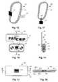
- FIGS. 1A-1H , 1 J, and 1 Kprovide illustrations of electronic payment device arrangements in various embodiments
- FIG. 2Aprovides an illustration of an exemplary embodiment of a passive transceiver for use with various embodiments of the invention
- FIGS. 2B-2Gprovide schematic illustrations of exemplary embodiments of active transceivers for use with various embodiments of the invention.
- FIGS. 3A and 3Bprovide illustrations of display configurations for electronic payment device arrangements in various embodiments
- FIG. 4provides illustrations of electronic payment devices attached to exemplary carriers in various embodiments
- FIG. 5provides a schematic illustration of an embodiment of an electronic payment system for use with various embodiments of the invention
- FIGS. 6A-6Cprovide system-level illustrations of system configurations for use with various embodiments of the invention.
- FIG. 7provides an illustration of an exemplary data configuration for use with host systems in various embodiments of the invention.
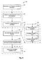
- FIG. 8provides a flow diagram summarizing methods for updating attributes for use with various embodiments of the invention.
- FIG. 9provides a flow diagram summarizing a more-detailed embodiment of a method for executing a payment transaction in various embodiments of the invention.
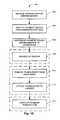
- FIG. 10provides a flow diagram summarizing methods of distributing electronic payment devices for use with various embodiments of the invention.
- Embodiments of the inventionprovide methods and systems for electronic payment involving transceiver-based payment device arrangements.
- FIGS. 1A-1Killustrate various embodiments of these arrangements, highlighting some exemplary configuration options.
- each arrangementis illustrated with only one transceiver. However, it will be appreciated that each arrangement may comprise multiple transceivers which may or may not be related to one another. Also, each transceiver is illustrated herein as a simple black box, roughly sized to accommodate typical transceiver circuitry. It will be appreciated, however, that there may exist many ways to produce a transceiver for use with the various embodiments of the invention. For example, processes have been demonstrated for printing passive radio-frequency identification (RFID) tags on sheets of polymer. The process involves affixing a small integrated circuit to the polymer and printing an antenna on the polymer using a special printer. Using a similar process, it may be possible to print a roll of RFID tags. A consumer may then buy a sheet of transceivers, similar to buying a sheet of postage stamps, tearing off individual transceivers at perforations in the polymer sheet.
- RFIDradio-frequency identification
- FIGS. 1A and 1Billustrate an exemplary arrangement 100 comprising a transceiver 102 , an attachment 104 , and packaging 106 .
- FIG. 1Bshows a section cut view of FIG. 1A taken at a-a.
- the attachment 104is shown coupled with the transceiver 102 .
- the attachment 104may be a square of double-sided adhesive, where one side is permanently adhered to the transceiver 102 , and the other side is temporarily covered with a removable paper like a wax paper. By removing the paper, the adhesive may become exposed, allowing a consumer to adhere the transceiver 102 to a carrier, like a watch (see discussion of FIG. 2 below for more on carriers).
- the attachment 104may be any chemical, mechanical, or other type of attachment suitable to attach the transceiver 102 to a carrier.
- suitable attachmentsmay include adhesives, pins, magnets, or threaded fasteners.
- attachmentsmay be generalized for a variety of carriers or customized to particular carriers; they may be permanent or temporary; and they may be fixed or removable.
- the packaging 106is shown removably coupled with the transceiver 102 and configured for display at a device purchase location.
- the packagingcomprises a molded sheet of transparent plastic 108 which is attached to a sheet of cardboard 110 using glue around three edges 112 . This forms a bubble 114 large enough to house the transceiver 102 .
- the packaging 106further comprises a cutout 116 punched through both the plastic 108 and cardboard 110 , and shaped to accommodate a typical display hook for a display at a device purchase location.
- the cardboard 110has a printed label 118 which displays certain product features, like the name and value, through the plastic 108 .
- FIGS. 1C and 1Dillustrate another exemplary arrangement 120 comprising a transceiver 122 , an attachment 124 , and packaging 126 .
- FIG. 1Dshows a section cut view of FIG. 1C taken at b-b.
- the packaging 126comprises an opaque plastic card 128 , approximately the dimensions of a typical credit card.
- the packaging 126is removably coupled with the transceiver 122 , by having the card 118 temporarily attached to the transceiver 128 using the attachment 124 .
- the packagingmay comprise the attachment.
- the packagingmay also comprise a printed label 138 .
- FIGS. 1E-1Fillustrate other of the many additional embodiments of electronic payment device arrangements.
- the attachmentcomprises a wristband 132 coupled to a transceiver 134 .
- the packagingcomprises a price tag 136 , removably coupled to the transceiver 134 via the attachment wristband 132 .
- the arrangementcomprises an elastic band 142 coupled to a transceiver 144 via a yoke 146 .
- the band 142may be used as packaging and hung from a hook or other display apparatus. Additionally, a consumer may use the band 142 as an attachment by securing the transceiver 144 to a carrier with the band 142 and yoke 146 .
- the attachmentmay comprise the packaging. Alternately, a consumer may remove the yoke 146 from the band 142 , and thread it onto a necklace or bracelet. In this way, the yoke 146 would become the attachment, and the band 142 would remain the removed packaging.
- FIGS. 1H-1Killustrate still other of the many additional embodiments of electronic payment device arrangements.
- FIG. 1Hshows a section cut view of FIG. 1G taken at c-c; and
- FIG. 1Kshows a section cut view of FIG. 1J taken at d-d.
- the packaging 152further comprises an enclosure 154 .
- the enclosure 154may removably enclose the transceiver 156 .
- FIG. 1Hshows the enclosure with a seam 162 , allowing the transceiver 156 to be removed from the enclosure 154 .
- pieces of the enclosure 154may be snapped together (e.g. by a friction fit connection) or screwed together (e.g. by a threaded connection). The pieces are molded so that when connected, a void 164 is formed in which the transceiver 156 may be stored.
- FIG. 1Halso shows an attachment 158 operatively coupled to the transceiver 156 by being directly coupled to the enclosure 154 .
- the enclosure 154may enclose both the transceiver 156 and an attachment, or a plurality of transceivers and attachments.
- the enclosure 154may be used as a carrier or it may be attached to a carrier.
- the enclosure 154may comprise the attachment.
- the enclosure 154may comprise magnets or fasteners, or it may even be molded to become the male or female portion of a connection point on a carrier.
- some arrangementsmay comprise purely aesthetic enclosures.
- the enclosure 154may comprise features to make the payment device more attractive to a consumer.
- the packaging in FIGS. 1G and 1Hfurther comprises a piece of cardboard 160 temporarily affixed to the enclosure 154 by the attachment 158 for display purposes.
- the enclosuremay be affixed to other packaging in many other ways. For example, it may be attached using shrink wrap, magnets, twist ties, Velcro, and molded connectors. It will also be appreciated that the enclosure may be displayed without extra packaging, and in at least that way, the enclosure may comprise the packaging.
- the packaging 162comprises a permanent enclosure 164 shaped like a gift card.
- the enclosure 164comprises a plurality of layers of material 166 enclosing the transceiver 168 .
- the various layers 166may be formed of the same or different materials in the same or different thicknesses. Further, the layers 166 may be assembled into the enclosure 164 in any appropriate way, including using adhesive, heat, or molded connections.
- the outer layersmay be thin plastic laminate glued to inner layers of cardboard. It will be appreciated that many other configurations of permanent enclosures are possible.
- the attachmentmay be configured to attach the transceiver to a carrier, either directly or via an enclosure. Anything capable of carrying the transceiver can become a carrier.
- FIGS. 2A-2Gillustrate a number of carrier configurations.
- FIGS. 2A-2Fillustrate various embodiments of carriers attached to transceivers without enclosures.
- a transceiver 202is attached to a carrier 200 with an attachment (not shown).
- One type of carrieris clothing and accessories, like the purse 200 - 1 , belt 200 - 2 , and hat 200 - 3 illustrated in FIGS. 2A-2C , respectively.
- Other carriers in this categoryinclude, but are not limited to, eyeglasses, jackets, shirts, pants, shoes, watches, and jewelry.
- Another type of carrieris portable electronic devices, like the music player 200 - 4 and cell phone 200 - 5 illustrated in FIGS. 2D and 2E , respectively.
- PDAportable digital assistants
- portable electronic gamesportable recorders
- pagersportable computers
- stationary-type goodslike the greeting card 200 - 6 illustrated in FIG. 2F
- Other carriers in this categoryinclude, but are not limited to, gift wrapping supplies, bags, notebooks, and writing implements.
- a transceivermay be desirable to attach to a credit card, a toy, a wheelchair, or a cane.
- special purpose clothing, accessories, and other carriersmay be made available to consumers.
- a beltmay comprise a Velcro patch sized and positioned for convenient attachment and removal of one or more payment devices.
- a consumermay purchase an electronic payment device in the arrangement illustrated by FIGS. 1A and 1B .
- the consumermay open the packaging 106 by separating the plastic 108 from the cardboard backing 110 .
- the consumermay then remove the transducer 102 from the bubble 114 in the plastic 108 , remove any backing to expose the attachment 104 , and use the attachment 104 to attach the transducer 102 to a carrier, such as the ones illustrated in FIGS. 2A-2F .
- a consumermay purchase an electronic payment device in the arrangement illustrated by FIGS. 1C and 1D .
- the consumermay remove the transceiver 122 by peeling the removable adhesive attachment 124 from the packaging 126 .
- the consumermay use the attachment 124 to attach the transceiver 122 to a carrier as in FIGS. 2A-2F .
- FIGS. 2A-2Fare illustrated without enclosures, it will be appreciated that many types of enclosures may be used in conjunction with the carrier types embodied in those and other illustrations.
- FIG. 2Ghighlights one exemplary embodiment wherein an enclosure is used as part of the attachment to the carrier.
- the transceiver 252is enclosed in an enclosure 254 .
- the enclosure 254is attached to a key ring 250 , which is acting as a carrier.
- the enclosure 254is similar to the various embodiments illustrated by FIGS. 1G and 1H , but with an added hole configured for a set of chain links 256 .
- the illustrated attachment to the carrier 250therefore comprises the enclosure 254 and set of chain links 256 .
- the key ringmay attach directly to the enclosure, or the attachment may comprise other elements, such as a karabiner or clip. It will be appreciated that the use of different types of enclosures may add numerous other potential embodiments for using the invention with many types of carriers.
- the illustrated arrangementscomprise packaging configured to display the payment device for sale at a device purchase location.
- a device purchase locationmay be a storefront, kiosk, vending machine, e-commerce website, or any other suitable location for purchasing an electronic payment device.
- the various device purchase locationsmay choose to display the payment device arrangements for sale in various ways. In some cases, the display will involve a display apparatus.
- FIGS. 3A and 3Billustrate two exemplary embodiments of displays comprising display apparatuses.
- the display 300comprises a rack 302 .
- the rack 302uses a plurality of hooks 304 to display a plurality of electronic payment device arrangements 306 .
- the hooks 304may be made of a number of materials (including plastic, metal, wood, ceramic, or composite) and in a number of shapes.
- Each hook 304may also be shaped to attach or to accommodate hardware to attach to the rack 302 , and the rack 302 may be configured to accommodate the attachment of the plurality of hooks 304 .
- the hooks 304are configured to accommodate arrangements such as those arrangements 100 , 130 , 140 , and 150 illustrated in FIGS. 1A , 1 E, 1 F, and 1 G, respectively.
- the display 350comprises a rack 352 .
- the rack 352uses a plurality of bins 354 to display a plurality of electronic payment device arrangements 356 .
- the bins 354may be semi- or fully-transparent in part or in whole to facilitate the display of various features of the electronic payment device arrangements 356 .
- the bins 354may be made of substantially transparent plastic, allowing a consumer to see the cash equivalence associated with the arrangements displayed in each bin.
- the bins 354may me made of any material and may be of any shape suitable for the display of electronic payment device arrangements 356 .
- the bins 354are configured to accommodate arrangements such as those arrangements 120 and 160 illustrated in FIGS. 1C and 1J , respectively.
- Both the hooks 304 of FIG. 3A and the bins 354 of FIG. 3Bmay further comprise advertisement information.
- This advertisement informationmay comprise logos, words, illustrations, images, sounds, lights, or any other way of enticing a consumer to purchase an electronic payment device arrangement. Further, the advertisement information may be incorporated into the hooks 304 or bins 354 , as with integrated circuitry or colored materials; or it may be applied to the hooks 304 or bins 354 , as with labels or paint.
- the plurality of hooks 304 or bins 354may be used to display arrangements with different characteristics.
- the illustrated arrangements 306 and 356comprise payment devices with different cash equivalents, like the $25 arrangements 306 - 1 and 356 - 1 and the $50 arrangement 306 - 2 and 356 - 2 .
- other featuresmay be desirable to display separately.
- different arrangementsmay comprise different aesthetic enclosures with different designs, or different numbers of transceivers per arrangement (e.g. single packs versus multi-packs).
- displaysmay comprise multiple types of display apparatuses configured to display multiple types of arrangements.
- the hooks 304 and bins 354 of FIGS. 3A and 3Bmay both be used on a single rack to display arrangements 306 and 356 simultaneously.
- the electronic payment devices described hereinmay be used in conjunction with an electronic payment system.
- the systemmay read the payment device and communicate with other financial systems and databases to execute financial transactions.
- the payment systems of the present inventionmake use of transceivers in various embodiments. Those transceivers may be active, passive, or semi-active (also called semi-passive).
- FIGS. 4A and 4Bshow illustrative embodiments of different types of transceivers.
- FIG. 4Aillustrates an exemplary passive transceiver which may be used with various embodiments of the invention.
- the transceiver 400comprises an integrated circuit (IC) 402 and an antenna 404 , attached to a backing 406 .
- the backing 406may comprise silicon, polymer, or any other suitable material.
- FIG. 4Billustrates an exemplary active transceiver which may be used with various embodiments of the invention.
- the active transceiver 450may comprise an integrated circuit (IC) 452 and an antenna 454 , attached to a backing 456 .
- the backing 456may similarly comprise silicon, polymer, or any other suitable material.
- the active transceiver 450may further comprise a battery 458 or other power supply.
- the power supply 458may be on board, or external to the transceiver 450 .
- the power 458may allow the transceiver 450 to support expanded memory 460 , and a more powerful antenna 454 .
- FIG. 4Bshows the antenna 454 attached externally to the transceiver backing 456 via a connector 462 . Similar antenna connectors to connector 462 may be used with any type of transceiver, though they are more common with active transceivers.
- FIG. 5provides an exemplary electronic payment system for use with various embodiments of the invention.
- the system 500may comprise an electronic payment device 510 , a reader 520 , a host system 530 , and a database 540 .
- the transceivermay comprise circuitry 512 and an antenna 514 .
- the reader 520may comprise an interrogator 522 , a decoder 524 , a power supply 526 , and an antenna 528 .
- the reader 520may also comprise an operative connection 550 to the host system 530 .
- the operative connection 550may include, but is not limited to, wired links, wireless links, virtual channel connections, satellite links, or any other suitable physical or virtual data channel.
- the reader 520may further comprise any connectors or other hardware or software needed to support the connection 550 to the host system 530 .
- the database 540may be separate from or a part of the host system 530 . Further, the database 540 may be localized, distributed, relational, or any other type or combination of types suitable to support embodiments of the invention.
- the database 540 and host system 530are operatively connected by any suitable data channel 552 and may further comprise elements necessary to support that data channel 552 .
- the reader 520may communicate with the payment device 510 by establishing either a physical or virtual data channel. Some readers 520 may require physical contact with the payment device 510 . In most cases, however, the communication with be established without contact through a virtual data channel.
- the reader 520 and payment device 510may communicate by transmitting optical or electromagnetic (e.g. radio-frequency) signals, or by sensing changes in electromagnetic fields.
- FIG. 5illustrates this connection as an electromagnetic field 560 .
- the systemmay be configured to transact with a passive transceiver (like the one illustrated by FIG. 4A ) as follows.
- the interrogator 522transmits a signal to the antenna 528 , which generates and emits an electromagnetic field 560 from the reader 520 .
- the shape, frequency, duty cycle, and other characteristics of the fieldmay be selected to accommodate certain design considerations. For example, where the reader is powered by battery, the field may be generated intermittently to conserve power.
- the field 560may induce a signal in the payment device's antenna 514 (e.g. through mutual inductance). This signal may in turn generate sufficient power to drive the transceiver circuitry 512 .
- the circuitry 512may then transmit a signal comprising a code from its antenna 514 back to the reader through the reader's antenna 528 .
- the decoder 524decodes the code and communicates relevant information with the host system 530 via the connection 550 .
- the codeallows the payment device to work with various embodiments of electronic payment systems. Some of these embodiments are illustrated in FIGS. 6A-6C .
- FIG. 6Aprovides an electronic payment system 600 comprising a plurality of electronic payment devices 602 , a reader 604 , a host system 606 , and a database 608 .
- the reader 604is operatively connected to the host system 606 through a network 610 .
- Each of the plurality of payment devices 602is configured to be read by the reader 604
- the reader 604is configured to read each of the plurality of payment devices 602 .
- the codeallows the reader 604 to identify each payment device 602 .
- a payment devicee.g. 602 - 1
- the device 602 - 1is induced to transmit a code stored in its memory.
- the memorymay have just enough capacity to store this code, or it may be capable of storing more.
- the codeidentifies to the reader 604 that the payment device 602 - 1 is nearby or is otherwise requesting a transaction.
- the codemay comprise a set of bits.
- the codemay or may not be unique in part or in whole for each device.
- multiple devicesmay be somehow linked with a common code.
- the codemay be effectively unique. Making the code effectively unique may involve distributing devices with similar or identical codes to remote geographical destinations, thereby minimizing the chance that two devices with the same code will be used in the same geographic region.
- the codemay be linked with one or more other identifiers. These other identifiers may include, but are not limited to, account numbers, biometric information, and point of sale identifiers.
- FIG. 6Bprovides an electronic payment system 620 similar to the system 600 illustrated in FIG. 6A .
- the embodiments illustrated by FIG. 6Bcomprise a plurality of host systems 626 and databases 628 .
- the electronic payment device 602 - 1when the electronic payment device 602 - 1 enters the field generated by the reader 604 , the device 602 - 1 may be induced to transmit a code back to the reader 604 . Because the reader is operatively connected to multiple host systems 626 , the reader must determine with which host system to communicate.
- the reader 604may transmit the code which identifies the payment device to multiple host systems 626 . Each host system 626 may then check to see if it is configured to transact with the device 602 associated with the code. For example, device 602 - 1 may be associated with an account which resides on database 628 - 1 . Thus, only host system 626 - 1 will find the payment device in its system and the other host systems ( 626 - 2 , 626 - 3 , and 626 - 4 ) will not participate in the transaction.
- the codemay comprise routing information.
- the reader 604may parse the routing information from the code.
- the routing informationmay be associated with a specific host system or a specific category of host systems.
- the reader 604may then use the routing information to determine with which host system or category of host systems to communicate.
- payment device 602 - 2may have been issued by Device Company, which owns host systems 628 - 3 and 628 - 4 .
- the device 602 - 2When the device 602 - 2 is used at a point of sale, it transmits a code to the reader 604 comprising routing information.
- the routing informationtells the reader 604 to transact only with one of host systems 628 - 3 or 628 - 4 .
- systems with multiple host systems 626may exist in many embodiments. Further, all or some of the host systems 626 may be interrelated or connected by other internal or external networks.
- the databases 628may be shared or distributed among multiple host systems 626 , and a single host system 626 may us multiple databases 628 .
- FIG. 6Cprovides an electronic payment system 650 comprising a device purchase location 652 , a plurality of points of sale 654 , and a plurality of host systems 656 .
- the device purchase location 652comprises a plurality of electronic payment devices 662 available for sale, and an activator 664 .
- the activator 664may be identical to the readers discussed herein, or may be specially configured to activate the electronic payment devices 662 .
- Each point of salecomprises a reader 666 . It will be appreciated that some or all of the activator and readers may be separate from or integrated with other payment systems. Further, one or more components of a reader, like an interrogator or antenna, may be integrated with another payment system.
- reader 666 - 1may be integrated into a magstripe reader at point of sale 654 - 1 .
- Some exemplary payment systems with which the activator or reader may be integratedare also described in U.S. Pat. Nos. 6,886,742, 6,827,260 and 7,086,584, the complete disclosures of which are herein incorporated by reference.
- the activator 664 and readers 666are all operatively connected to the host systems 656 through a network 660 .
- activationmay involve the packaging or attachment.
- packagingmay be configured so that removal of the packaging allows or causes activation of the payment device.
- each databasecomprises a set of attributes associated with each electronic payment device.
- An exemplary embodiment of this databaseis illustrated in FIG. 7 .
- the databasemay be used with various embodiments of the invention, including those illustrated by FIGS. 5 and 6 A- 6 C.
- the database 700is illustrated as a relational table, with attributes 702 represented by columns and values 706 represented by rows. It will be appreciated that many data structures may be suitable for storing this database, including flat files, arrays, and relationally-managed database systems (RMDBS). Further, the headings, values, arrangement, and other illustrated features of the data represent only a small subset of the potential data types, values, and configurations. Thus, the sorted array 700 illustrated by FIG. 7 is intended only as one embodiment of the data.
- the database 700 in FIG. 7comprises a set of attributes 702 related to a code 704 associated with a payment device (not shown).
- the set of attributesmay comprise an account number 702 - 1 designating the account associated with the payment device, an ACTIVE flag 702 - 2 representing the active or inactive status of the payment device, a balance 702 - 3 reflecting the current cash equivalence of the payment device, an any number of other attributes ( 702 - 4 through 702 -N).
- many codeswill exist, each with its own set of related attribute values ( 706 - 1 through 706 -N).
- row 706 - 1provides attribute values relating to a device with code 00000001 ( 706 - 1 , 704 ).
- the devicerelates to account number 419352801 ( 706 - 1 , 702 - 1 ), which is active ( 706 - 1 , 702 - 2 ) and carries a remaining balance of $1.93 ( 706 - 1 , 702 - 3 ).
- Thismay be the condition of a payment device in use by a consumer.
- the devicemay have been pre-loaded with a cash equivalent, some of which has been expended.
- the account numbermay be any number which identifies the related account, including a number relating to the owner of the device, activator, reader, or host system; or a number which is randomly, semi-randomly, sequentially, or algorithmically generated.
- row 706 - 2provides attribute values relating to a device with code 00000002 ( 706 - 2 , 704 ). Perhaps because the balance of the device has reached $0.00 ( 706 - 2 , 702 - 3 ), the device and its related account ( 706 - 2 , 702 - 1 ) have become inactive ( 706 - 2 , 702 - 2 ).
- a device accountmay automatically de-activate when the balance reaches zero.
- the device holdermay have to de-activate the account.
- itmay also be possible to recharge (i.e. add money to) the balance. In those and other embodiments, it may be undesirable to automatically deactivate the account upon reaching a zero balance.
- row 706 - 5provides attribute values relating to a device with code 00000005 ( 706 - 5 , 704 ).
- This devicemay have been pre-loaded with a balance of $50.00 ( 706 - 5 , 702 - 3 ).
- the deviceis associated with an account ( 706 - 5 , 702 - 1 )
- the accounthas not yet been activated ( 706 - 5 , 702 - 2 ).
- This conditionmay occur at an intermediate stage of activation, after an account has been chosen but before it has been activated.
- the conditionmay also occur in embodiments where selection of an associated account occurs separate from and preceding activation of the account. For example, a point of sale or host system may automatically associate account numbers with a set of payment devices before the devices are distributed or sold.
- row 706 -Nprovides attribute values relating to a device with code 49758201 ( 706 -N, 704 ).
- This devicemay have been pre-loaded with a balance of $25.00 ( 706 -N, 702 - 3 ).
- the deviceis not associated with an account ( 706 -N, 702 - 1 ) and is inactive ( 706 -N, 702 - 2 ).
- sets of devicesmay be distributed (e.g. to wholesalers, device purchase locations, or consumers) without associated accounts.
- Account management optionsmay provide potential benefits in areas including code and device reuse, security, and customer management.
- the various payment systems of the present inventionmay be used to execute methods for payment and other transactions related to electronic payment devices.
- FIG. 8provides various embodiments of methods for using an electronic payment device with an electronic payment system.
- the method 800begins with the provision 802 of electronic payment devices. This may occur at a device purchase location where the devices may be provided to consumers for purchase.
- the electronic payment devicemay comprise at least one transceiver, an attachment, and packaging.
- the transceiverPrior to using the device, the transceiver may need to be removed 808 from its packaging.
- a consumeralso may desire to attach 810 the transceiver to a carrier.
- a consumermay attach the transceiver to a belt and use the transceiver (e.g. make a purchase) with the transceiver attached. Once the consumer returns home, the consumer may then desire to move the transceiver from the belt to a purse for storage or future transactions.
- the attachmentmay also be such that the transceiver is removed for use.
- a consumermay have the transceiver in an enclosure attached to a belt. To use the transceiver, the consumer may remove the transceiver from the enclosure or remove the enclosure from the belt.
- special carrierssuch as special purpose clothing and accessories may cause the transceiver to require or not require removal for use.
- an instruction and signalmay be received 804 .
- the signalmay comprise a code associated with the transceiver.
- one or both of the instruction and signalmay be transmitted from the transceiver to a reader.
- the readerreads 822 the signal transmitted by the transceiver.
- the signalis then transmitted 824 to a host system, and the host system receives 826 the signal.
- the instructionmay be generated by the reader, and in other embodiments, the instruction may be generated by the host system.
- the host systemmay be operatively connected to one or more databases in various embodiments of the invention including those illustrated in FIGS. 5 and 6 A- 6 C.
- the databasecomprises a set of attributes related to the codes associated with the transceivers.
- An exemplary embodiment of the databaseis illustrated in FIG. 7 .
- the host systemmay query the database to find the attributes related to the code associated with the transceiver being used. Related attributes may then be updated or interrogated 806 as instructed by the instruction.
- updating or interrogating 806 related attributesmay affect or determine the state of a transceiver or an associated account.
- various interrogate instructionsmay be passed from the reader to the host system to determine whether an account is active, what balance remains in an account, or other information. These interrogate instructions may further comprise validate or authorize instructions.
- a consumermay wish to activate or de-activate a payment device.
- the readermay pass an activate instruction to the host system, which may cause the ACTIVE flag 702 - 2 to toggle. This may activate or de-activate the account associated with the transceiver.
- a consumermay wish to recharge the balance on the account associated with the payment device.
- the readermay pass a recharge instruction to the host system, which may cause the balance 702 - 3 to increment by some predetermined amount.
- a consumermay wish to execute 812 a payment transaction, such as purchasing a good or service.
- the readermay pass a payment instruction to the host system, which may cause the balance 702 - 3 to decrement by the amount of the purchase.
- FIG. 9provides an exemplary method 900 in which both update and interrogate instructions are used.
- This method 900may be executed when an electronic payment device is used to attempt a payment transaction at a point of sale.
- the methodbegins by checking 902 an account balance. This balance may be associated with the account relating to the payment device being used.
- the stepmay be performed in a number of ways, including by passing an interrogate instruction from the reader to the host system, and having the host system interrogate a balance field in the database.
- a decision 904is then reached as to whether the balance is appropriate for the transaction. If the transaction is a purchase, an appropriate balance may require sufficient funds to exist in the account for making the purchase. Other types of transactions may be possible, as well. For example, certain types of transactions may require minimum or maximum balances, or certain transactions may increment balances (e.g. returns).
- the methodmay adjust 908 the balance to reflect the execution of the transaction. For example, if the transaction is a purchase, the balance may be decremented by the amount of the purchase.
- the transactionmay fail.
- the balancemay still proceed.
- a purchase transactionmay be allowed to proceed even without sufficient funds, causing the balance to decrement to a negative value.
- one or more attributesmay be updated 912 to reflect the failed transaction.
- the failure to transactmay be communicated 914 back to the reader. This may be accomplished actively, for example by transmitting a signal from the host system to the reader; or it may be accomplished passively, for example by not transmitting a signal telling the reader that a transaction was successful. In the latter case, the reader may wait for some predetermined amount of time, after which it may assume that the transaction was unsuccessful.
- the readermay be configured to communicate the failed transaction to the consumer.
- FIG. 10provides methods 1000 for distributing electronic payment device arrangements to consumers.
- Electronic payment device arrangementsare received 1002 .
- the arrangementsmay be received in may different embodiments, including those illustrated in FIGS. 1A-1K .
- the arrangementsmay be received at a device purchase location from a distributor.
- the device purchase locationmay also be its own distributor.
- the payment device arrangementsare displayed 1004 for sale.
- the device purchase locationmay display the arrangements in many different ways, including the ways illustrated in FIGS. 3A and 3B .
- the arrangementsare then distributed 1006 to consumers. They may be offered for sale, given away for promotional or other reasons.
- the device purchase locationmay provide an activator, as in the embodiment illustrated in FIG. 6C . Consumers may use the activator to activate the transceiver (or the account associated with the payment device).
- the transceivermay be removed 1010 from its packaging and attached 1012 to a carrier, as in the embodiments illustrated in FIGS. 2A-2G .
- the transceivermay be used to execute a transaction, like a payment transaction. This may be accomplished, for example, by an embodiment of the method provided by FIG. 8 .
Landscapes
- Business, Economics & Management (AREA)
- Engineering & Computer Science (AREA)
- Accounting & Taxation (AREA)
- General Business, Economics & Management (AREA)
- Strategic Management (AREA)
- Physics & Mathematics (AREA)
- General Physics & Mathematics (AREA)
- Theoretical Computer Science (AREA)
- Computer Networks & Wireless Communication (AREA)
- Finance (AREA)
- Development Economics (AREA)
- Economics (AREA)
- Microelectronics & Electronic Packaging (AREA)
- Cash Registers Or Receiving Machines (AREA)
Abstract
Description
Claims (19)
Priority Applications (1)
| Application Number | Priority Date | Filing Date | Title |
|---|---|---|---|
| US13/169,088US8296233B2 (en) | 2006-10-09 | 2011-06-27 | Electronic payment instrument and packaging |
Applications Claiming Priority (2)
| Application Number | Priority Date | Filing Date | Title |
|---|---|---|---|
| US11/539,858US7991692B2 (en) | 2006-10-09 | 2006-10-09 | Electronic payment instrument and packaging |
| US13/169,088US8296233B2 (en) | 2006-10-09 | 2011-06-27 | Electronic payment instrument and packaging |
Related Parent Applications (1)
| Application Number | Title | Priority Date | Filing Date |
|---|---|---|---|
| US11/539,858ContinuationUS7991692B2 (en) | 2006-10-09 | 2006-10-09 | Electronic payment instrument and packaging |
Publications (2)
| Publication Number | Publication Date |
|---|---|
| US20110315762A1 US20110315762A1 (en) | 2011-12-29 |
| US8296233B2true US8296233B2 (en) | 2012-10-23 |
Family
ID=39304712
Family Applications (2)
| Application Number | Title | Priority Date | Filing Date |
|---|---|---|---|
| US11/539,858Active2028-01-01US7991692B2 (en) | 2006-10-09 | 2006-10-09 | Electronic payment instrument and packaging |
| US13/169,088ActiveUS8296233B2 (en) | 2006-10-09 | 2011-06-27 | Electronic payment instrument and packaging |
Family Applications Before (1)
| Application Number | Title | Priority Date | Filing Date |
|---|---|---|---|
| US11/539,858Active2028-01-01US7991692B2 (en) | 2006-10-09 | 2006-10-09 | Electronic payment instrument and packaging |
Country Status (1)
| Country | Link |
|---|---|
| US (2) | US7991692B2 (en) |
Cited By (2)
| Publication number | Priority date | Publication date | Assignee | Title |
|---|---|---|---|---|
| USD691610S1 (en) | 2011-11-07 | 2013-10-15 | Blackberry Limited | Device smart card |
| US8950681B2 (en) | 2011-11-07 | 2015-02-10 | Blackberry Limited | Universal integrated circuit card apparatus and related methods |
Families Citing this family (7)
| Publication number | Priority date | Publication date | Assignee | Title |
|---|---|---|---|---|
| US7991692B2 (en)* | 2006-10-09 | 2011-08-02 | First Data Corporation | Electronic payment instrument and packaging |
| US7885878B2 (en)* | 2008-05-28 | 2011-02-08 | First Data Corporation | Systems and methods of payment account activation |
| US20100125932A1 (en)* | 2008-11-21 | 2010-05-27 | Rahmi Halk | Martial arts student identification system |
| US8500031B2 (en)* | 2010-07-29 | 2013-08-06 | Bank Of America Corporation | Wearable article having point of sale payment functionality |
| US9177307B2 (en) | 2010-07-29 | 2015-11-03 | Bank Of America Corporation | Wearable financial indicator |
| KR101655834B1 (en) | 2013-08-08 | 2016-09-09 | 연세대학교 산학협력단 | Method, apparatus, system and recoding medium for recommendation of sound source |
| JP6601918B2 (en)* | 2017-09-28 | 2019-11-06 | 本田技研工業株式会社 | Gear position detection device |
Citations (89)
| Publication number | Priority date | Publication date | Assignee | Title |
|---|---|---|---|---|
| US4106062A (en) | 1976-05-12 | 1978-08-08 | Addressograph Multigraph Corp. | Apparatus for producing magnetically encoded articles |
| US4855583A (en) | 1987-08-17 | 1989-08-08 | Figgie International, Inc. | Structure and method of making combination proximity/insertion identification cards |
| US5074593A (en) | 1989-12-04 | 1991-12-24 | John Grosso | Insert holder with sealable opening |
| US5518122A (en) | 1991-08-09 | 1996-05-21 | Westinghouse Electric Corp. | Modular mail processing method and control system |
| US5585787A (en) | 1991-12-09 | 1996-12-17 | Wallerstein; Robert S. | Programmable credit card |
| US5913203A (en) | 1996-10-03 | 1999-06-15 | Jaesent Inc. | System and method for pseudo cash transactions |
| US5918909A (en) | 1996-04-19 | 1999-07-06 | Barry Fiala, Inc. | Package for card with data-encoded strip and method of using same |
| US5921584A (en) | 1995-06-30 | 1999-07-13 | Ssi Photo I.D. | Card display package |
| US5936227A (en) | 1996-02-23 | 1999-08-10 | Orga Kartensysteme Gmbh | Plastics card comprising a mini-smart-card which can be separated therefrom |
| US5955961A (en) | 1991-12-09 | 1999-09-21 | Wallerstein; Robert S. | Programmable transaction card |
| US6224108B1 (en) | 2000-03-07 | 2001-05-01 | Western Graphics And Data, Inc. | Packaged data card assembly |
| US6248199B1 (en) | 1999-04-26 | 2001-06-19 | Soundcraft, Inc. | Method for the continuous fabrication of access control and identification cards with embedded electronics or other elements |
| US6299530B1 (en) | 1998-05-05 | 2001-10-09 | Kenneth W. Hansted | Integrated transaction card and packaging |
| US20010034565A1 (en)* | 1998-04-22 | 2001-10-25 | Leatherman Russel Dean | Rfid tag location using tag or host interaction record |
| US6353420B1 (en) | 1999-04-28 | 2002-03-05 | Amerasia International Technology, Inc. | Wireless article including a plural-turn loop antenna |
| US6356196B1 (en) | 2000-09-29 | 2002-03-12 | Jaesent Inc. | Verified receipt, notification, and theft deterrence of courier-delivered parcels |
| US20020049669A1 (en)* | 2000-05-10 | 2002-04-25 | Michael Bleser | Method of selling giftcards |
| US6422464B1 (en)* | 1997-09-26 | 2002-07-23 | Gilbarco Inc. | Fuel dispensing system providing customer preferences |
| US20020096570A1 (en) | 2001-01-25 | 2002-07-25 | Wong Jacob Y. | Card with a dynamic embossing apparatus |
| US6471127B2 (en)* | 2000-07-06 | 2002-10-29 | Bank Of America Corporation | Data card |
| US20030014891A1 (en)* | 2000-12-08 | 2003-01-23 | Nelms David W. | Non-rectangular shaped credit card with case |
| US6535726B1 (en)* | 2000-01-12 | 2003-03-18 | Gilbarco Inc. | Cellular telephone-based transaction processing |
| US20030061168A1 (en) | 2001-09-21 | 2003-03-27 | Larry Routhenstein | Method for generating customer secure card numbers |
| US20030069846A1 (en)* | 2001-10-09 | 2003-04-10 | Robert Victor Marcon | Multi-function electronic transaction card |
| US6561432B1 (en) | 1999-01-19 | 2003-05-13 | Giesecke & Devrient Gmbh | Portable data support with a break-off mini-chip card |
| US6588658B1 (en) | 2000-06-23 | 2003-07-08 | Eric Blank | Transaction card with attached auxiliary member |
| US6592044B1 (en) | 2000-05-15 | 2003-07-15 | Jacob Y. Wong | Anonymous electronic card for generating personal coupons useful in commercial and security transactions |
| US20030150919A1 (en) | 2000-06-23 | 2003-08-14 | Eric Blank | Transaction card with attached auxiliary portion |
| US20030150762A1 (en)* | 2002-02-13 | 2003-08-14 | Biller Richard L. | Card package assembly and method |
| US6607127B2 (en) | 2001-09-18 | 2003-08-19 | Jacob Y. Wong | Magnetic stripe bridge |
| US6609654B1 (en) | 2000-05-15 | 2003-08-26 | Privasys, Inc. | Method for allowing a user to customize use of a payment card that generates a different payment card number for multiple transactions |
| US20030167207A1 (en)* | 2001-07-10 | 2003-09-04 | Berardi Michael J. | System and method for incenting payment using radio frequency identification in contact and contactless transactions |
| US6644555B1 (en) | 1999-05-07 | 2003-11-11 | Njc Innovations | Chip card comprising an antenna |
| US20030222153A1 (en)* | 2000-07-06 | 2003-12-04 | Jamily Pentz | Data card |
| US20030225623A1 (en)* | 2002-01-04 | 2003-12-04 | John Wankmueller | Method and system for conducting transactions using a payment card with account information encoded in bar code |
| US6685097B1 (en) | 1998-09-24 | 2004-02-03 | Gemplus | Smart card comprising a removable minicard and method for making same |
| US6688529B1 (en) | 2000-10-06 | 2004-02-10 | Reg. Oklahoma Acquisitions, Llc | Method of making transaction card assemblies |
| US20040039860A1 (en)* | 1999-05-11 | 2004-02-26 | Socket Communications, Inc. | Nested removable-removable modules with game and media-player applications |
| US6702185B1 (en) | 2002-11-13 | 2004-03-09 | Identicard Systems, Incorporated | Identification device having an integrated circuit |
| US6727802B2 (en) | 1996-04-01 | 2004-04-27 | Guy M. Kelly | Anti-tear protection for smart card transactions |
| US20040089724A1 (en)* | 2002-11-07 | 2004-05-13 | Ellen Lasch | Foldable transaction card |
| US6753341B1 (en) | 1999-03-12 | 2004-06-22 | Joslin Diabetes Cancer, Inc. | Inhibition of PKC to treat permability failure |
| US20040127256A1 (en)* | 2002-07-30 | 2004-07-01 | Scott Goldthwaite | Mobile device equipped with a contactless smart card reader/writer |
| US20040129785A1 (en) | 2001-11-06 | 2004-07-08 | Luu Daniel V. H. | Contactless SIM card carrier with detachable antenna and carrier therefore |
| US20040131760A1 (en) | 2003-01-02 | 2004-07-08 | Stuart Shakespeare | Apparatus and method for depositing material onto multiple independently moving substrates in a chamber |
| US6761319B2 (en) | 1998-01-22 | 2004-07-13 | Mondex International Limited | Configuration of IC card |
| US20040144846A1 (en)* | 2003-01-28 | 2004-07-29 | Ellen Lasch | Compact or convenient transaction cards |
| US6805288B2 (en) | 2000-05-15 | 2004-10-19 | Larry Routhenstein | Method for generating customer secure card numbers subject to use restrictions by an electronic card |
| US6811082B2 (en) | 2001-09-18 | 2004-11-02 | Jacob Y. Wong | Advanced magnetic stripe bridge (AMSB) |
| US20040225613A1 (en)* | 2003-05-05 | 2004-11-11 | International Business Machines Corporation | Portable intelligent shopping device |
| US6817530B2 (en) | 2001-12-18 | 2004-11-16 | Digimarc Id Systems | Multiple image security features for identification documents and methods of making same |
| US20040230535A1 (en)* | 2002-10-07 | 2004-11-18 | Philip Binder | Method and system for conducting off-line and on-line pre-authorized payment transactions |
| US6827264B2 (en) | 2000-11-13 | 2004-12-07 | Gemplus | Concurrent electrical customization and graphic printing of a smart card |
| US6827260B2 (en) | 1999-08-09 | 2004-12-07 | First Data Corporation | Systems and methods for utilizing a point-of-sale system |
| US20040256469A1 (en)* | 1999-09-07 | 2004-12-23 | American Express Travel Related Services Company, Inc. | A system and method for manufacturing a punch-out rfid transaction device |
| US20050004921A1 (en)* | 2003-05-09 | 2005-01-06 | American Express Travel Related Services Company, Inc. | Systems and methods for providing a rf transaction device operable to store multiple distinct accounts |
| US20050033686A1 (en)* | 2001-07-10 | 2005-02-10 | American Express Travel Related Services Company, Inc. | System and method for securing sensitive information during completion of a transaction |
| US20050038718A1 (en)* | 2001-07-10 | 2005-02-17 | American Express Travel Related Services Company, Inc. | Method and system for facilitating a shopping experience |
| US20050035847A1 (en)* | 2001-07-10 | 2005-02-17 | American Express Travel Related Services Company, Inc. | Systems and methods for providing a rf transaction device for use in a private label transaction |
| US20050061889A1 (en) | 2003-09-19 | 2005-03-24 | First Data Corporation | Financial presentation instruments with integrated holder and methods for use |
| US6886742B2 (en) | 1999-08-09 | 2005-05-03 | First Data Corporation | Systems and methods for deploying a point-of sale device |
| US20050104718A1 (en) | 2003-11-19 | 2005-05-19 | First Data Corporation | Automated preparation of radio-frequency devices for distribution |
| US20050121512A1 (en)* | 2001-12-06 | 2005-06-09 | John Wankmueller | Method and system for conducting transactions using a payment card with two technologies |
| US20050137986A1 (en) | 2003-12-17 | 2005-06-23 | First Data Corporation | Methods and systems for electromagnetic initiation of secure transactions |
| US6912398B1 (en) | 2000-04-10 | 2005-06-28 | David Domnitz | Apparatus and method for delivering information to an individual based on location and/or time |
| US20050177480A1 (en) | 2004-01-20 | 2005-08-11 | Silicon Valley Micro C Corporation | Intelligent billing system |
| US20050205665A1 (en)* | 2003-12-10 | 2005-09-22 | Ellen Lasch | Foldable transaction card systems for non-traditionally-sized transaction cards |
| US20050211760A1 (en)* | 2004-03-23 | 2005-09-29 | First Data Corporation | System and method for preparing RF devices for delivery and verifying delivery information |
| US20050230485A1 (en)* | 2004-04-20 | 2005-10-20 | Ross Bruce E | Specially shaped smart card for compact applications |
| US20050248459A1 (en)* | 2001-07-10 | 2005-11-10 | American Express Marketing & Development Corp. | A system and method for providing an rfid transaction device |
| US20050247798A1 (en) | 2004-05-07 | 2005-11-10 | Graves Phillip C | Card assembly with vertical magnetic stripe |
| US20060028319A1 (en) | 2004-08-04 | 2006-02-09 | First Data Corporation | Radio-frequency-device personalization |
| US7070095B1 (en)* | 2002-11-07 | 2006-07-04 | American Express Travel Related Services Company, Inc. | Foldable transaction cards and methods of making the same |
| US20060151348A1 (en)* | 2005-01-11 | 2006-07-13 | Wow! Technologies, Inc. | Rack-hung loadable debit card package |
| US7086584B2 (en) | 1999-08-09 | 2006-08-08 | First Data Corporation | Systems and methods for configuring a point-of-sale system |
| US7097108B2 (en) | 2004-10-28 | 2006-08-29 | Bellsouth Intellectual Property Corporation | Multiple function electronic cards |
| US7137552B1 (en)* | 2003-12-10 | 2006-11-21 | American Express Travel Related Services Company, Inc. | Portable electronic devices interconnected with convenient or foldable transaction cards |
| US7147151B2 (en)* | 2002-12-11 | 2006-12-12 | American Express Travel Related Services Company, Inc. | Foldable transaction card systems |
| US7168615B2 (en)* | 2001-09-24 | 2007-01-30 | E2Interactive, Inc. | Keycard for automating transaction requests |
| US20070084913A1 (en)* | 2005-10-18 | 2007-04-19 | Capital One Financial Corporation | Systems and methods for authorizing a transaction for a financial account |
| US7234637B2 (en) | 2004-04-06 | 2007-06-26 | Datacard Corporation | High-speed personalization machine |
| US7239226B2 (en)* | 2001-07-10 | 2007-07-03 | American Express Travel Related Services Company, Inc. | System and method for payment using radio frequency identification in contact and contactless transactions |
| US20070162381A1 (en)* | 2005-12-28 | 2007-07-12 | Compucredit Intellectual Holdings Corp. Ii | Method for providing financial instruments to customers of a service provider |
| US20070266605A1 (en)* | 2006-05-19 | 2007-11-22 | Target Brands, Inc. | Stored-value product with manufactured article |
| US20070288371A1 (en)* | 2006-05-25 | 2007-12-13 | Johnson Aratha M | Personal electronic payment system and related method |
| US7309007B2 (en)* | 2005-10-04 | 2007-12-18 | First Data Corporation | Systems and methods for personalizing transaction cards |
| US20080046747A1 (en)* | 2006-07-28 | 2008-02-21 | Brown Steven T | Authorization system and method |
| US20080061151A1 (en)* | 2006-09-08 | 2008-03-13 | Simon Phillips | Identification of installable card |
| US7991692B2 (en)* | 2006-10-09 | 2011-08-02 | First Data Corporation | Electronic payment instrument and packaging |
Family Cites Families (1)
| Publication number | Priority date | Publication date | Assignee | Title |
|---|---|---|---|---|
| WO2001088659A2 (en) | 2000-05-15 | 2001-11-22 | Privasys | Electronic cards capable of being read by a magnetic stripe reader and methods for their use |
- 2006
- 2006-10-09USUS11/539,858patent/US7991692B2/enactiveActive
- 2011
- 2011-06-27USUS13/169,088patent/US8296233B2/enactiveActive
Patent Citations (100)
| Publication number | Priority date | Publication date | Assignee | Title |
|---|---|---|---|---|
| US4106062A (en) | 1976-05-12 | 1978-08-08 | Addressograph Multigraph Corp. | Apparatus for producing magnetically encoded articles |
| US4855583A (en) | 1987-08-17 | 1989-08-08 | Figgie International, Inc. | Structure and method of making combination proximity/insertion identification cards |
| US5074593A (en) | 1989-12-04 | 1991-12-24 | John Grosso | Insert holder with sealable opening |
| US5518122A (en) | 1991-08-09 | 1996-05-21 | Westinghouse Electric Corp. | Modular mail processing method and control system |
| US5955961A (en) | 1991-12-09 | 1999-09-21 | Wallerstein; Robert S. | Programmable transaction card |
| US5585787A (en) | 1991-12-09 | 1996-12-17 | Wallerstein; Robert S. | Programmable credit card |
| US5921584A (en) | 1995-06-30 | 1999-07-13 | Ssi Photo I.D. | Card display package |
| US5936227A (en) | 1996-02-23 | 1999-08-10 | Orga Kartensysteme Gmbh | Plastics card comprising a mini-smart-card which can be separated therefrom |
| US6727802B2 (en) | 1996-04-01 | 2004-04-27 | Guy M. Kelly | Anti-tear protection for smart card transactions |
| US5918909A (en) | 1996-04-19 | 1999-07-06 | Barry Fiala, Inc. | Package for card with data-encoded strip and method of using same |
| US5937394A (en) | 1996-10-03 | 1999-08-10 | Jaesent, Inc. | System and method for pseudo cash transactions with credit back |
| US5956699A (en) | 1996-10-03 | 1999-09-21 | Jaesent Inc. | System for secured credit card transactions on the internet |
| US5913203A (en) | 1996-10-03 | 1999-06-15 | Jaesent Inc. | System and method for pseudo cash transactions |
| US6422464B1 (en)* | 1997-09-26 | 2002-07-23 | Gilbarco Inc. | Fuel dispensing system providing customer preferences |
| US6761319B2 (en) | 1998-01-22 | 2004-07-13 | Mondex International Limited | Configuration of IC card |
| US20010034565A1 (en)* | 1998-04-22 | 2001-10-25 | Leatherman Russel Dean | Rfid tag location using tag or host interaction record |
| US6299530B1 (en) | 1998-05-05 | 2001-10-09 | Kenneth W. Hansted | Integrated transaction card and packaging |
| US6685097B1 (en) | 1998-09-24 | 2004-02-03 | Gemplus | Smart card comprising a removable minicard and method for making same |
| US6561432B1 (en) | 1999-01-19 | 2003-05-13 | Giesecke & Devrient Gmbh | Portable data support with a break-off mini-chip card |
| US6753341B1 (en) | 1999-03-12 | 2004-06-22 | Joslin Diabetes Cancer, Inc. | Inhibition of PKC to treat permability failure |
| US6248199B1 (en) | 1999-04-26 | 2001-06-19 | Soundcraft, Inc. | Method for the continuous fabrication of access control and identification cards with embedded electronics or other elements |
| US6353420B1 (en) | 1999-04-28 | 2002-03-05 | Amerasia International Technology, Inc. | Wireless article including a plural-turn loop antenna |
| US6644555B1 (en) | 1999-05-07 | 2003-11-11 | Njc Innovations | Chip card comprising an antenna |
| US20040039860A1 (en)* | 1999-05-11 | 2004-02-26 | Socket Communications, Inc. | Nested removable-removable modules with game and media-player applications |
| US6886742B2 (en) | 1999-08-09 | 2005-05-03 | First Data Corporation | Systems and methods for deploying a point-of sale device |
| US6827260B2 (en) | 1999-08-09 | 2004-12-07 | First Data Corporation | Systems and methods for utilizing a point-of-sale system |
| US7086584B2 (en) | 1999-08-09 | 2006-08-08 | First Data Corporation | Systems and methods for configuring a point-of-sale system |
| US20040256469A1 (en)* | 1999-09-07 | 2004-12-23 | American Express Travel Related Services Company, Inc. | A system and method for manufacturing a punch-out rfid transaction device |
| US7093767B2 (en)* | 1999-09-07 | 2006-08-22 | American Express Travel Related Services Company, Inc. | System and method for manufacturing a punch-out RFID transaction device |
| US6535726B1 (en)* | 2000-01-12 | 2003-03-18 | Gilbarco Inc. | Cellular telephone-based transaction processing |
| US6224108B1 (en) | 2000-03-07 | 2001-05-01 | Western Graphics And Data, Inc. | Packaged data card assembly |
| US6912398B1 (en) | 2000-04-10 | 2005-06-28 | David Domnitz | Apparatus and method for delivering information to an individual based on location and/or time |
| US20020049669A1 (en)* | 2000-05-10 | 2002-04-25 | Michael Bleser | Method of selling giftcards |
| US6609654B1 (en) | 2000-05-15 | 2003-08-26 | Privasys, Inc. | Method for allowing a user to customize use of a payment card that generates a different payment card number for multiple transactions |
| US20050086160A1 (en) | 2000-05-15 | 2005-04-21 | Wong Jacob Y. | Method for implementing anonymous credit card transactions using a fictitious account name |
| US20050086177A1 (en) | 2000-05-15 | 2005-04-21 | Anderson Roy L. | Method for customizing payment card transactions at the time of the transactions |
| US6592044B1 (en) | 2000-05-15 | 2003-07-15 | Jacob Y. Wong | Anonymous electronic card for generating personal coupons useful in commercial and security transactions |
| US6805288B2 (en) | 2000-05-15 | 2004-10-19 | Larry Routhenstein | Method for generating customer secure card numbers subject to use restrictions by an electronic card |
| US20050082362A1 (en) | 2000-05-15 | 2005-04-21 | Anderson Roy L. | Anonymous merchandise delivery system |
| US20050080747A1 (en) | 2000-05-15 | 2005-04-14 | Anderson Roy Lee | Method for generating customer one-time unique purchase order numbers |
| US20030150919A1 (en) | 2000-06-23 | 2003-08-14 | Eric Blank | Transaction card with attached auxiliary portion |
| US6588658B1 (en) | 2000-06-23 | 2003-07-08 | Eric Blank | Transaction card with attached auxiliary member |
| US6471127B2 (en)* | 2000-07-06 | 2002-10-29 | Bank Of America Corporation | Data card |
| US20030222153A1 (en)* | 2000-07-06 | 2003-12-04 | Jamily Pentz | Data card |
| US6356196B1 (en) | 2000-09-29 | 2002-03-12 | Jaesent Inc. | Verified receipt, notification, and theft deterrence of courier-delivered parcels |
| US6688529B1 (en) | 2000-10-06 | 2004-02-10 | Reg. Oklahoma Acquisitions, Llc | Method of making transaction card assemblies |
| US6827264B2 (en) | 2000-11-13 | 2004-12-07 | Gemplus | Concurrent electrical customization and graphic printing of a smart card |
| US20030014891A1 (en)* | 2000-12-08 | 2003-01-23 | Nelms David W. | Non-rectangular shaped credit card with case |
| US20020096570A1 (en) | 2001-01-25 | 2002-07-25 | Wong Jacob Y. | Card with a dynamic embossing apparatus |
| US20030167207A1 (en)* | 2001-07-10 | 2003-09-04 | Berardi Michael J. | System and method for incenting payment using radio frequency identification in contact and contactless transactions |
| US7239226B2 (en)* | 2001-07-10 | 2007-07-03 | American Express Travel Related Services Company, Inc. | System and method for payment using radio frequency identification in contact and contactless transactions |
| US7429927B2 (en)* | 2001-07-10 | 2008-09-30 | American Express Travel Related Services Company, Inc. | System and method for providing and RFID transaction device |
| US20050035847A1 (en)* | 2001-07-10 | 2005-02-17 | American Express Travel Related Services Company, Inc. | Systems and methods for providing a rf transaction device for use in a private label transaction |
| US20050033686A1 (en)* | 2001-07-10 | 2005-02-10 | American Express Travel Related Services Company, Inc. | System and method for securing sensitive information during completion of a transaction |
| US20050248459A1 (en)* | 2001-07-10 | 2005-11-10 | American Express Marketing & Development Corp. | A system and method for providing an rfid transaction device |
| US20050038718A1 (en)* | 2001-07-10 | 2005-02-17 | American Express Travel Related Services Company, Inc. | Method and system for facilitating a shopping experience |
| US6811082B2 (en) | 2001-09-18 | 2004-11-02 | Jacob Y. Wong | Advanced magnetic stripe bridge (AMSB) |
| US6607127B2 (en) | 2001-09-18 | 2003-08-19 | Jacob Y. Wong | Magnetic stripe bridge |
| US20030061168A1 (en) | 2001-09-21 | 2003-03-27 | Larry Routhenstein | Method for generating customer secure card numbers |
| US7168615B2 (en)* | 2001-09-24 | 2007-01-30 | E2Interactive, Inc. | Keycard for automating transaction requests |
| US20030069846A1 (en)* | 2001-10-09 | 2003-04-10 | Robert Victor Marcon | Multi-function electronic transaction card |
| US20040129785A1 (en) | 2001-11-06 | 2004-07-08 | Luu Daniel V. H. | Contactless SIM card carrier with detachable antenna and carrier therefore |
| US20050121512A1 (en)* | 2001-12-06 | 2005-06-09 | John Wankmueller | Method and system for conducting transactions using a payment card with two technologies |
| US6817530B2 (en) | 2001-12-18 | 2004-11-16 | Digimarc Id Systems | Multiple image security features for identification documents and methods of making same |
| US20030225623A1 (en)* | 2002-01-04 | 2003-12-04 | John Wankmueller | Method and system for conducting transactions using a payment card with account information encoded in bar code |
| US20030150762A1 (en)* | 2002-02-13 | 2003-08-14 | Biller Richard L. | Card package assembly and method |
| US20040127256A1 (en)* | 2002-07-30 | 2004-07-01 | Scott Goldthwaite | Mobile device equipped with a contactless smart card reader/writer |
| US20040230535A1 (en)* | 2002-10-07 | 2004-11-18 | Philip Binder | Method and system for conducting off-line and on-line pre-authorized payment transactions |
| US7070095B1 (en)* | 2002-11-07 | 2006-07-04 | American Express Travel Related Services Company, Inc. | Foldable transaction cards and methods of making the same |
| US20070158435A1 (en)* | 2002-11-07 | 2007-07-12 | Ellen Lasch | Foldable transaction card |
| US20040089724A1 (en)* | 2002-11-07 | 2004-05-13 | Ellen Lasch | Foldable transaction card |
| US6702185B1 (en) | 2002-11-13 | 2004-03-09 | Identicard Systems, Incorporated | Identification device having an integrated circuit |
| US7147151B2 (en)* | 2002-12-11 | 2006-12-12 | American Express Travel Related Services Company, Inc. | Foldable transaction card systems |
| US20040131760A1 (en) | 2003-01-02 | 2004-07-08 | Stuart Shakespeare | Apparatus and method for depositing material onto multiple independently moving substrates in a chamber |
| US20040144846A1 (en)* | 2003-01-28 | 2004-07-29 | Ellen Lasch | Compact or convenient transaction cards |
| US20040225613A1 (en)* | 2003-05-05 | 2004-11-11 | International Business Machines Corporation | Portable intelligent shopping device |
| US20050004921A1 (en)* | 2003-05-09 | 2005-01-06 | American Express Travel Related Services Company, Inc. | Systems and methods for providing a rf transaction device operable to store multiple distinct accounts |
| US20050061889A1 (en) | 2003-09-19 | 2005-03-24 | First Data Corporation | Financial presentation instruments with integrated holder and methods for use |
| US7293704B2 (en)* | 2003-11-13 | 2007-11-13 | E2Interactive, Inc. | Keycard for automating transaction requests |
| US20050104718A1 (en) | 2003-11-19 | 2005-05-19 | First Data Corporation | Automated preparation of radio-frequency devices for distribution |
| US20050205665A1 (en)* | 2003-12-10 | 2005-09-22 | Ellen Lasch | Foldable transaction card systems for non-traditionally-sized transaction cards |
| US7137552B1 (en)* | 2003-12-10 | 2006-11-21 | American Express Travel Related Services Company, Inc. | Portable electronic devices interconnected with convenient or foldable transaction cards |
| US20050137986A1 (en) | 2003-12-17 | 2005-06-23 | First Data Corporation | Methods and systems for electromagnetic initiation of secure transactions |
| US20050177480A1 (en) | 2004-01-20 | 2005-08-11 | Silicon Valley Micro C Corporation | Intelligent billing system |
| US7104439B2 (en) | 2004-03-23 | 2006-09-12 | First Data Corporation | System and method for preparing RF devices for delivery and verifying delivery information |
| US20050211760A1 (en)* | 2004-03-23 | 2005-09-29 | First Data Corporation | System and method for preparing RF devices for delivery and verifying delivery information |
| US7234637B2 (en) | 2004-04-06 | 2007-06-26 | Datacard Corporation | High-speed personalization machine |
| US20050230485A1 (en)* | 2004-04-20 | 2005-10-20 | Ross Bruce E | Specially shaped smart card for compact applications |
| US20050247798A1 (en) | 2004-05-07 | 2005-11-10 | Graves Phillip C | Card assembly with vertical magnetic stripe |
| US20060028319A1 (en) | 2004-08-04 | 2006-02-09 | First Data Corporation | Radio-frequency-device personalization |
| US7097108B2 (en) | 2004-10-28 | 2006-08-29 | Bellsouth Intellectual Property Corporation | Multiple function electronic cards |
| US20060151348A1 (en)* | 2005-01-11 | 2006-07-13 | Wow! Technologies, Inc. | Rack-hung loadable debit card package |
| US7309007B2 (en)* | 2005-10-04 | 2007-12-18 | First Data Corporation | Systems and methods for personalizing transaction cards |
| US20070084913A1 (en)* | 2005-10-18 | 2007-04-19 | Capital One Financial Corporation | Systems and methods for authorizing a transaction for a financial account |
| US20070162381A1 (en)* | 2005-12-28 | 2007-07-12 | Compucredit Intellectual Holdings Corp. Ii | Method for providing financial instruments to customers of a service provider |
| US20070266605A1 (en)* | 2006-05-19 | 2007-11-22 | Target Brands, Inc. | Stored-value product with manufactured article |
| US20070288371A1 (en)* | 2006-05-25 | 2007-12-13 | Johnson Aratha M | Personal electronic payment system and related method |
| US20080046747A1 (en)* | 2006-07-28 | 2008-02-21 | Brown Steven T | Authorization system and method |
| US20080061151A1 (en)* | 2006-09-08 | 2008-03-13 | Simon Phillips | Identification of installable card |
| US7991692B2 (en)* | 2006-10-09 | 2011-08-02 | First Data Corporation | Electronic payment instrument and packaging |
Non-Patent Citations (12)
| Title |
|---|
| "Citibank Lauches PayPass keyfob", Cards International, Sep. 17, 2005, n. 345, pp. 1-2.* |
| "Fujitsu and Accelitec Form Strategic Alliance for RFID-Based Transaction Systems; Fujitsu to Resell and Integrae Accelitec's Pay Pilot Application Suite into its Pervasive Retailing Framework", Business Wire, Apr. 25, 2006, pp. 1-2.* |
| "OTI Receives First Commercial Orders from Hypercom Corporation for 'Contactless' Reader Solutions", PR Newswire. New York: Mar. 1, 2005, pp. 1-3.* |
| "PowerPay RFID Payment and Marketing Solution Speeds Concession Purchases at Seahawks Stadium with Technology from Texas Instruments", PR Newswire. New York: Nov. 11, 2003, pp. 1-2.* |
| Author Unknown, "QI Systems Developing Products for RFID-Enabled Smart Card Applications," Wireless News, NA, Jul. 22, 2005, 1 page. |
| Author Unknown, "SmartMetric Card With Embedded Fingerprint Scanner is Foolproof Internet Payment/Transaction Solution; Credit Card-Sized Product is Versatile, Practical; Touching Surface Validates Cardholder, Eliminating Need to Transmit Credit/Debit Account Numbers," PR Newswire, Jun. 19, 2006, 3 pages. |
| Author Unknown, "TI Embraces Prox Card Standard: Texas Instrument's ISO 14443 payment platform promises faster data transfer rates and more security." RFID Journal Mar. 6, 2003, Retrieved from http://rfidjournal.com/article/articleprint/327/-1/1, accessed May 31, 2007, 1 page. |
| Gadgets galor, But where's the Next SpeedPass (Exxon Mobil Corp), American Banker, Mar. 23, 2004, v 169, n56, pp. 1-4.* |
| KuyKendall, Lavonne, "Amex Starts Promoting its ExpressPay System in Phoenix", American Banker. New York, N.Y.: Jul. 22, 2003, vol. 168, iss. 168, iss 139; pp. 1-4.* |
| Lucas, et al., "Adding convenience to wireless payments," Credit Card Management, Nov. 1, 2003. vol. 16, Issue 9, 4 pages. |
| Lucas, Peter and Fitzgerald, Kate, "Adding Convenience to wireless payments", Credit Card Management. New York: Nov. 2003. vol. 16, iss. 9, pp. 1-4.* |
| QI Systems Developing Products for RFID-Enabled Smart Card Applications ce.(Brief Article), Wireless News, NA, Jul. 22, 2005, p. 1.* |
Cited By (4)
| Publication number | Priority date | Publication date | Assignee | Title |
|---|---|---|---|---|
| USD691610S1 (en) | 2011-11-07 | 2013-10-15 | Blackberry Limited | Device smart card |
| USD692005S1 (en)* | 2011-11-07 | 2013-10-22 | Blackberry Limited | Device smart card |
| USD702694S1 (en) | 2011-11-07 | 2014-04-15 | Blackberry Limited | Device smart card |
| US8950681B2 (en) | 2011-11-07 | 2015-02-10 | Blackberry Limited | Universal integrated circuit card apparatus and related methods |
Also Published As
| Publication number | Publication date |
|---|---|
| US7991692B2 (en) | 2011-08-02 |
| US20110315762A1 (en) | 2011-12-29 |
| US20080086418A1 (en) | 2008-04-10 |
Similar Documents
| Publication | Publication Date | Title |
|---|---|---|
| US8296233B2 (en) | Electronic payment instrument and packaging | |
| US6224108B1 (en) | Packaged data card assembly | |
| US7063255B2 (en) | Card display system and method | |
| US6439613B2 (en) | Multiple-component data package | |
| US7374095B2 (en) | Transaction card and envelope assembly | |
| US7370805B2 (en) | Transaction card comprising two magnetic stripes | |
| US20100019029A1 (en) | Two-section reloadable financial transaction product | |
| US7293701B2 (en) | Financial transaction card with frame | |
| US7815108B2 (en) | Transaction product with electrical circuit | |
| JP5318087B2 (en) | Packaging for portable consumer devices | |
| CN101631681B (en) | Stored value card package with a combined upc and activation magnetic stripe | |
| MX2007005673A (en) | Activation number generation and association. | |
| US7885878B2 (en) | Systems and methods of payment account activation | |
| US20140076975A1 (en) | Magnetic Strips, 2-D Bar Codes And QR Codes For Products | |
| CN102859533A (en) | electronic sales method | |
| US20100155490A1 (en) | Transaction product with slide viewer | |
| US20050137940A1 (en) | Method to provide a product to a consumer to protect consumer privacy | |
| US20080116259A1 (en) | Non-cash media card and the process for dispensing from automated teller | |
| CA2398520A1 (en) | Internet related discount coupon rebate business method | |
| CN103164795A (en) | Electronic transaction and logistics system | |
| EP2171650B1 (en) | A radio frequency transponder | |
| JP2005149289A (en) | Voucher information management system, voucher information management server, and sheet with prepaid card | |
| CN202331558U (en) | electronic trading system | |
| JP4249539B2 (en) | Sales promotion system | |
| JP3169374U (en) | Communication amulet |
Legal Events
| Date | Code | Title | Description |
|---|---|---|---|
| STCF | Information on status: patent grant | Free format text:PATENTED CASE | |
| AS | Assignment | Owner name:CREDIT SUISSE AG, CAYMAN ISLANDS BRANCH, NEW YORK Free format text:SECURITY AGREEMENT;ASSIGNORS:FIRST DATA CORPORATION;CLOVER NETWORKS, INC.;MONEY NETWORK FINANCIAL, LLC;REEL/FRAME:030080/0531 Effective date:20130320 | |
| AS | Assignment | Owner name:WELLS FARGO BANK, NATIONAL ASSOCIATION, AS COLLATERAL AGENT, UNITED STATES Free format text:SECURITY INTEREST;ASSIGNOR:FIRST DATA CORPORATION;REEL/FRAME:036656/0224 Effective date:20150811 Owner name:WELLS FARGO BANK, NATIONAL ASSOCIATION, AS COLLATE Free format text:SECURITY INTEREST;ASSIGNOR:FIRST DATA CORPORATION;REEL/FRAME:036656/0224 Effective date:20150811 | |
| FPAY | Fee payment | Year of fee payment:4 | |
| AS | Assignment | Owner name:MONEY NETWORK FINANCIAL, LLC, COLORADO Free format text:RELEASE BY SECURED PARTY;ASSIGNOR:CREDIT SUISSE AG, CAYMAN ISLANDS BRANCH;REEL/FRAME:049899/0001 Effective date:20190729 Owner name:FIRST DATA CORPORATION, COLORADO Free format text:RELEASE BY SECURED PARTY;ASSIGNOR:CREDIT SUISSE AG, CAYMAN ISLANDS BRANCH;REEL/FRAME:049899/0001 Effective date:20190729 Owner name:CLOVER NETWORK, INC., CALIFORNIA Free format text:RELEASE BY SECURED PARTY;ASSIGNOR:CREDIT SUISSE AG, CAYMAN ISLANDS BRANCH;REEL/FRAME:049899/0001 Effective date:20190729 | |
| AS | Assignment | Owner name:FIRST DATA CORPORATION, NEW YORK Free format text:TERMINATION AND RELEASE OF SECURITY INTEREST IN PATENT RIGHTS;ASSIGNOR:WELLS FARGO BANK, NATIONAL ASSOCIATION;REEL/FRAME:050094/0455 Effective date:20190729 | |
| MAFP | Maintenance fee payment | Free format text:PAYMENT OF MAINTENANCE FEE, 8TH YEAR, LARGE ENTITY (ORIGINAL EVENT CODE: M1552); ENTITY STATUS OF PATENT OWNER: LARGE ENTITY Year of fee payment:8 | |
| MAFP | Maintenance fee payment | Free format text:PAYMENT OF MAINTENANCE FEE, 12TH YEAR, LARGE ENTITY (ORIGINAL EVENT CODE: M1553); ENTITY STATUS OF PATENT OWNER: LARGE ENTITY Year of fee payment:12 |