US8295920B2 - System for detecting fluid changes and sensoring devices therefor - Google Patents
System for detecting fluid changes and sensoring devices thereforDownload PDFInfo
- Publication number
- US8295920B2 US8295920B2US10/576,333US57633304AUS8295920B2US 8295920 B2US8295920 B2US 8295920B2US 57633304 AUS57633304 AUS 57633304AUS 8295920 B2US8295920 B2US 8295920B2
- Authority
- US
- United States
- Prior art keywords
- antenna element
- antenna
- pair
- sensor
- sensor device
- Prior art date
- Legal status (The legal status is an assumption and is not a legal conclusion. Google has not performed a legal analysis and makes no representation as to the accuracy of the status listed.)
- Active, expires
Links
Images


Classifications
- A—HUMAN NECESSITIES
- A61—MEDICAL OR VETERINARY SCIENCE; HYGIENE
- A61B—DIAGNOSIS; SURGERY; IDENTIFICATION
- A61B5/00—Measuring for diagnostic purposes; Identification of persons
- A61B5/0002—Remote monitoring of patients using telemetry, e.g. transmission of vital signals via a communication network
- A61B5/0004—Remote monitoring of patients using telemetry, e.g. transmission of vital signals via a communication network characterised by the type of physiological signal transmitted
- A—HUMAN NECESSITIES
- A61—MEDICAL OR VETERINARY SCIENCE; HYGIENE
- A61B—DIAGNOSIS; SURGERY; IDENTIFICATION
- A61B5/00—Measuring for diagnostic purposes; Identification of persons
- A61B5/05—Detecting, measuring or recording for diagnosis by means of electric currents or magnetic fields; Measuring using microwaves or radio waves
- A61B5/0507—Detecting, measuring or recording for diagnosis by means of electric currents or magnetic fields; Measuring using microwaves or radio waves using microwaves or terahertz waves
- A—HUMAN NECESSITIES
- A61—MEDICAL OR VETERINARY SCIENCE; HYGIENE
- A61B—DIAGNOSIS; SURGERY; IDENTIFICATION
- A61B5/00—Measuring for diagnostic purposes; Identification of persons
- A61B5/05—Detecting, measuring or recording for diagnosis by means of electric currents or magnetic fields; Measuring using microwaves or radio waves
- A61B5/053—Measuring electrical impedance or conductance of a portion of the body
- A61B5/0537—Measuring body composition by impedance, e.g. tissue hydration or fat content
- A—HUMAN NECESSITIES
- A61—MEDICAL OR VETERINARY SCIENCE; HYGIENE
- A61B—DIAGNOSIS; SURGERY; IDENTIFICATION
- A61B5/00—Measuring for diagnostic purposes; Identification of persons
- A61B5/41—Detecting, measuring or recording for evaluating the immune or lymphatic systems
- A61B5/411—Detecting or monitoring allergy or intolerance reactions to an allergenic agent or substance
- A—HUMAN NECESSITIES
- A61—MEDICAL OR VETERINARY SCIENCE; HYGIENE
- A61B—DIAGNOSIS; SURGERY; IDENTIFICATION
- A61B5/00—Measuring for diagnostic purposes; Identification of persons
- A61B5/48—Other medical applications
- A61B5/4869—Determining body composition
- A61B5/4875—Hydration status, fluid retention of the body
- A61B5/4878—Evaluating oedema
- A—HUMAN NECESSITIES
- A61—MEDICAL OR VETERINARY SCIENCE; HYGIENE
- A61B—DIAGNOSIS; SURGERY; IDENTIFICATION
- A61B5/00—Measuring for diagnostic purposes; Identification of persons
- A61B5/68—Arrangements of detecting, measuring or recording means, e.g. sensors, in relation to patient
- A61B5/6801—Arrangements of detecting, measuring or recording means, e.g. sensors, in relation to patient specially adapted to be attached to or worn on the body surface
- A61B5/683—Means for maintaining contact with the body
- A61B5/6832—Means for maintaining contact with the body using adhesives
- A61B5/6833—Adhesive patches
- A—HUMAN NECESSITIES
- A61—MEDICAL OR VETERINARY SCIENCE; HYGIENE
- A61M—DEVICES FOR INTRODUCING MEDIA INTO, OR ONTO, THE BODY; DEVICES FOR TRANSDUCING BODY MEDIA OR FOR TAKING MEDIA FROM THE BODY; DEVICES FOR PRODUCING OR ENDING SLEEP OR STUPOR
- A61M5/00—Devices for bringing media into the body in a subcutaneous, intra-vascular or intramuscular way; Accessories therefor, e.g. filling or cleaning devices, arm-rests
- A61M5/14—Infusion devices, e.g. infusing by gravity; Blood infusion; Accessories therefor
- A61M5/168—Means for controlling media flow to the body or for metering media to the body, e.g. drip meters, counters ; Monitoring media flow to the body
- A61M5/16831—Monitoring, detecting, signalling or eliminating infusion flow anomalies
- A61M5/16836—Monitoring, detecting, signalling or eliminating infusion flow anomalies by sensing tissue properties at the infusion site, e.g. for detecting infiltration
- A—HUMAN NECESSITIES
- A61—MEDICAL OR VETERINARY SCIENCE; HYGIENE
- A61B—DIAGNOSIS; SURGERY; IDENTIFICATION
- A61B2562/00—Details of sensors; Constructional details of sensor housings or probes; Accessories for sensors
- A61B2562/02—Details of sensors specially adapted for in-vivo measurements
- A—HUMAN NECESSITIES
- A61—MEDICAL OR VETERINARY SCIENCE; HYGIENE
- A61B—DIAGNOSIS; SURGERY; IDENTIFICATION
- A61B2562/00—Details of sensors; Constructional details of sensor housings or probes; Accessories for sensors
- A61B2562/04—Arrangements of multiple sensors of the same type
- A61B2562/046—Arrangements of multiple sensors of the same type in a matrix array
- A—HUMAN NECESSITIES
- A61—MEDICAL OR VETERINARY SCIENCE; HYGIENE
- A61M—DEVICES FOR INTRODUCING MEDIA INTO, OR ONTO, THE BODY; DEVICES FOR TRANSDUCING BODY MEDIA OR FOR TAKING MEDIA FROM THE BODY; DEVICES FOR PRODUCING OR ENDING SLEEP OR STUPOR
- A61M2205/00—General characteristics of the apparatus
- A61M2205/35—Communication
- A61M2205/3507—Communication with implanted devices, e.g. external control
- A61M2205/3523—Communication with implanted devices, e.g. external control using telemetric means
Definitions
- the present inventionrelates generally to the detection of fluid and/or other material in tissue, and especially, to systems, methods and/or devices for detecting changes in the level of fluid in tissue.
- the systems, methods and/or devices of the present inventiondetect if fluid level has increased or, has otherwise become abnormal.
- edemais an abnormal accumulation of watery fluid in the intercellular spaces of connective tissue. Edematous tissues are swollen and, when punctured, secrete a thin incoagulable fluid. Edema is most frequently a symptom of disease rather than a disease in itself, and it may have a number of causes, most of which can be traced back to gross variations in the physiological mechanisms that normally maintain a constant water balance in the cells, tissues, and blood. Among the causes may be diseases of the kidneys, heart, veins, or lymphatic system; malnutrition; or allergic reactions.
- Hematomascan, for example,)occur beneath the outermost of three membranes that cover the brain (meninges) as a result of a head injury.
- An acute subdural hematomaoccurs soon after a severe head injury.
- a chronic subdural hematomais a complication that may develop weeks after a head injury. Such a head injury may have been so minor that the patient does not remember it.
- An epidural hematomais a traumatic accumulation of blood between the inner table of the skull and the stripped-off dural membrane. The inciting event often is a focused blow to the head. It is often difficult to detect hematomas, particularly when the hematoma occurs well after the time of an injury.
- Extravasation or infiltrationis the accidental infusion or leakage of an injection fluid such as a contrast medium or a therapeutic agent into tissue surrounding a blood vessel rather than into the blood vessel itself.
- Extravasationcan be caused, for example, by rupture or dissection of fragile vasculature, valve disease, inappropriate needle placement, or patient movement resulting in the infusing needle being pulled from the intended vessel or causing the needle to be pushed through the wall of the vessel.
- High injection pressures and/or rates of some modern procedurescan increase the risk of extravasation.
- contrast injection flow ratescan be in the range of 0.1 to 10 ml/s.
- Extravasationcan cause serious injury to patients.
- certain injection fluidssuch as contrast media or chemotherapy drugs can be toxic to tissue. It is, therefore, very important when performing fluid injections to detect extravasation as soon as possible and discontinue the injection upon detection.
- extravasation detection techniquesTwo simple and very useful techniques for detecting extravasation are palpation of the patient in the vicinity of the injection site and simple visual observation of the vicinity of the injection site by a trained health care provider.
- the health care providermanually senses swelling of tissue near the injection site resulting from extravasation.
- visual observationit is also sometimes possible to observe directly any swelling of the skin in the vicinity of an injection site resulting from extravasation.
- mercury strain gauge plethysmographsmeasure the volume change resulting from venous blood flow in a cross sectional area of a limb of a patient.
- Air cuff or pulse volume recorder plethysmographsmeasure the changes in pressure within a recording cuff.
- Such plethysmographscan be cumbersome to operate and/or insensitive to small changes in volume.
- Impedance plethysmographsuse low-frequency electromagnetic energy transmitted via galvanic contact with the skin to measure changes in the electrical impedance in a defined tissue volume of a limb. Detection of extravasation via impedance changes is disclosed, for example, in U.S. Pat. Nos. 5,964,703 and 5,947,910. In this method, an impedance change of a certain level relative to a baseline measurement in the vicinity of the injection site is interpreted as being an extravasation. A change in impedance occurs during extravasation because injection fluid in the tissue of the patient changes both the volume and the electrical impedance properties of the tissue.
- Use of electrodes in impedance plethysmographscan, however, result in instabilities. For example, maintaining suitable electrical (ohmic or galvanic) contact between the electrodes of impedance plethysmographs and the skin of the patient is often very difficult.
- Photo-plethysmographsmeasure the optical scattering properties of capillary blood to detect the presence of extravasated fluids in tissue.
- An example of a photo-plethysmographis described in U.S. Pat. No. 4,877,034. Because light is heavily absorbed in tissue, however, the sensitivity of photo-plethysmographs is generally limited to the top 1 ⁇ 4 inch of tissue. Many extravasations, however, occur deeper than 1 ⁇ 4 inch. Moreover, the injection medium may flow into interstitial spaces remote from the photoplethysmograph sensors and go undetected.
- a number of extravasation detection devicesattempt to measure temperature differences to determine if an extravasation has occurred.
- U.S. Pat. No. 4,647,281discloses subcutaneous temperature sensing of extravasation to trigger an alarm.
- an antenna and a microwave radiometerinstantaneously measure the temperature of the subcutaneous tissue at the site where fluid is injected by measuring microwave radiation emitted naturally from the body.
- An algorithmperiodically determines the temperature difference between tissue and injected fluid, and compares the difference to a fixed threshold.
- An alarm processoruses the comparison to determine an alarm condition.
- U.S. Pat. No. 5,334,141discloses a microwave extravasation detection system employing a reusable microwave antenna and a disposable attachment element for releasably securing the microwave antenna to a patient's skin over an injection site.
- the attachment elementholds the antenna in intimate contact with the patient's skin to optimize microwave transfer therebetween, while shielding the antenna from environmental noise signals.
- U.S. Pat. No. 5,954,668also discloses use of a microwave antenna to sense temperature of tissue to detect extravasation. Although measurement of temperature changes and emissivity using microwave energy can result in instantaneous detection, temperature differences are often too small for practical measurement.
- U.S. Pat. No. 4,240,445discloses detection of pulmonary edema via transmitting electromagnetic energy through a transmission line coupled to tissue.
- U.S. Pat. No. 4,690,149discloses detection of brain edema via impedance changes detected by a sensor.
- a proposed method of detection of brain edemais also disclosed in U.S. Pat. No. 6,233,479, in which a measured signal from a microwave antenna is compared to a stored characteristic edema signal.
- Microwave energyhas also been used for the detection of tumors in living tissue as described in U.S. Pat. No. 6,061,589.
- U.S. Pat. No. 6,061,589disclosed transmission of electromagnetic energy into the body (breast tissue) using a microwave antenna in and a resultant signal is measured.
- U.S. Pat. No. 6,061,589describes a microwave antenna to detect incipient tumors in accordance with differences in relative dielectric characteristics. Electromagnetic energy in the microwave frequency range is, applied to a discrete volume in the tissue and scattered signal returns are collected. The irradiated location is shifted or changed in a predetermined scanning pattern. The returned signals are processed to detect anomalies indicative of the present of a tumor.
- Microwave energyhas also been used as in non-invasive tomographic spectroscopy imaging. See U.S. Pat. Nos. 6,332,087 and 6,026,173. Microwave energy has further been used to measure the fat content in nonliving organic tissue.
- the fat content of pelagic and other fatty species of fishis proportion to water content.
- the dielectric properties of the fishdepend on the water content. In the device of Kent, changes in transmission properties of the fish were calibrated against water content.
- the present inventionprovides a sensor device for detecting a change in the level of fluid within tissue of a body including: a housing having a plurality of bridge segments, the bridge segments connecting at intersections and being arranged to circumscribe an opening defined by the housing; and a plurality of antenna elements at least partially seated within the housing at intersections of the bridge segments.
- Each of the plurality of antenna elementsincludes a generally planar antenna mounted to a substrate material at a base of the planar antenna. An outer surface of the planar antenna faces away from the substrate.
- Each of the plurality of antenna elementsfurther includes an electrical shield surrounding the substrate.
- the sensor devicefurther includes an RF cable assembly for each of the antenna elements.
- Each of the RF cable assembliesincludes at one end thereof a connector. At the other end thereof, the RF cable assembly is electrically connected to the antenna element corresponding thereto.
- the sensor devicecan additionally or alternatively include at least one flexible circuit board assembly for transmission of energy to and from the antenna elements.
- the flexible circuit boardcan include at least one splitter such that electromagnetic energy can be transmitted to at least two of the plurality of antenna elements using a single transmission trace within the flexible circuit board.
- the flexible circuit boardcan include at least one combiner such that electromagnetic energy can be received from at least two of the plurality of antenna elements and carried by a single transmission trace within the flexible circuit board.
- the sensor devicecan further include an attachment mechanism to operably attach the sensor device to the tissue of the body.
- the attachment mechanismcan include an adhesive portion defining a cutout region generally coextensive with the opening of the housing.
- the adhesive portionhas one side thereof coated with a first adhesive adapted to removably attach to the tissue and an opposite side thereof coated with a second adhesive adapted to attach to a bottom surface of the housing.
- the attachment mechanismcan further include a release band affixed to a perimeter of the adhesive portion.
- the first adhesiveis adapted to facilitate removal of the attachment mechanism from the patient.
- the first adhesivecan provide less adhesion than the second adhesive.
- each of the plurality of antenna elements of the sensor deviceincludes at least a first antenna element pair and a second antenna element pair.
- the first antenna element pairincludes a first transmitting antenna element and a first receiving antenna element.
- the second antenna element pairincludes a second transmitting antenna element and a second receiving antenna element.
- the first antenna element pair and the second antenna element paircan be spaced from each other to create an area of reduced sensitivity between the first antenna element pair and the second antenna element pair.
- the space between the first antenna element pair and the second antenna element paircan be set so that the sensor is insensitive to fluid changes of a predetermined volume within the area of reduces sensitivity.
- a first area of higher sensitivitycan be defined by the area between the first transmitting antenna element and the first receiving antenna element.
- a second area of higher sensitivitycan be defined by the area between the second transmitting antenna element and the second receiving antenna element.
- the present inventionprovides a sensor for detecting a change in the level of fluid within tissue of a body including a first antenna pair including a first transmitting antenna and a first receiving antenna.
- the first transmitting antennais spaced from and connected to the first receiving antenna by a first bridging segment.
- the sensorfurther includes at least a second antenna pair including a second transmitting antenna and a second receiving antenna.
- the second transmitting antennais spaced from and connected to the second receiving antenna by a second bridging segment.
- the first antenna pair and the second antenna pairare placed in spaced connection by a first spacing segment and a second spacing segment so that an open area is defined by the first antenna pair, the second antenna pair, the first spacing segment and the second spacing segment.
- Each antenna elementcan be surrounded by a housing section.
- Each of the antenna elementscan include a substrate mounted within the housing section and a generally planar antenna element mounted to the substrate.
- the first bridging segmentconnects the housing section of the first transmitting antenna to the housing section of the first receiving antenna
- the second bridging segmentconnects the housing section of the second transmitting antenna to the housing section of the second receiving antenna.
- the first spacing segmentcan connect the housing section of the first transmitting antenna to the housing section of the second transmitting antenna
- the second spacing segmentcan connect the housing section of the first receiving antenna to the housing section of the second receiving antenna.
- the first spacing segment and the second spacing segmentcan space the first antenna pair and the second antenna pair to create an area of reduced sensitivity between the first antenna pair and the second antenna pair.
- the present inventionprovides a system for wirelessly communicating a change in the level of fluid within tissue of a body.
- the systemincludes: a sensor device for detecting a change in the level of fluid within the tissue; a transmitter in operative connection with the sensor device for receiving therefrom a signal indicative of the change in the level of fluid within the tissue and for transmitting a wireless signal indicative of the change in level of fluid; and a remote receiver for receiving the wireless signal transmitted by the transmitter.
- the remote receivercan include an indicator to provide an alert of a state determined from the received wireless signal.
- the sensor devicecan include a housing having a plurality of bridge segments, wherein the bridge segments connect at intersections and are arranged to circumscribe an opening defined by the housing.
- the sensor devicefurther includes a plurality of antenna elements at least partially seated within the housing at intersections of the bridge segments.
- Each of the plurality of antenna elementscan include a generally planar antenna mounted to a substrate material at a base of the planar antenna. An outer surface of the planar antenna faces away from the substrate.
- Each of the plurality of antenna elementsfurther includes an electrical shield surrounding the substrate.
- the sensor devicein another embodiment, includes a first antenna pair including a first transmitting antenna and a first receiving antenna.
- the first transmitting antennais spaced from and connected to the first receiving antenna by a first bridging segment.
- the sensor devicefurther includes at least a second antenna pair including a second transmitting antenna and a second receiving antenna
- the second transmitting antennais spaced from and connected to the second receiving antenna by a second bridging segment.
- the first antenna pair and the second antenna paircan be placed in spaced connection by a first spacing segment and a second spacing segment so that an open area is defined by the first antenna pair, the second antenna pair, the first spacing segment and the second spacing segment.
- the sensor deviceincludes a first antenna pair including a first transmitting antenna and a first receiving antenna
- the first transmitting antennais spaced from and connected to the first receiving antenna by a first bridging segment.
- the sensor devicefurther includes at least a second antenna pair including a second transmitting antenna and a second receiving antenna.
- the second transmitting antennais spaced from and connected to the second receiving antenna by a second bridging segment.
- the first antenna pairis spaced from the second antenna pair by at least one spacing segment so that an area of reduced sensitivity is created in the space between the first antenna pair and the second antenna pair.
- the present inventionprovides an attachment mechanism for use in attaching a sensing device to the skin of a patient including: an adhesive portion having a first side coated with a first adhesive adapted to removably attach to the skin and a second side, opposite the first side and coated with a second adhesive adapted to attach to the sensing device; and a release band affixed to a perimeter of the adhesive portion to facilitate removal of the attachment mechanism from attachment to the skin.
- the adhesive portioncan, for example, define a cutout region generally coextensive with an opening defined by the sensing device.
- the first adhesivecan be adapted to facilitate removal of the attachment mechanism from attachment to the skin.
- the first adhesivecan, for example, provide less adhesion than said second adhesive.
- the present inventionprovides a method of sensing a change in fluid level in living tissue in a patient including: placing a first antenna pair in contact with the patient, the first antenna pair including a first transmitting antenna and a first receiving antenna; and placing a second antenna pair in contact with the patient, the second antenna pair including a second transmitting antenna and a second receiving antenna
- the first antenna pair and the second antenna pairare spaced when in contact with the patient to create an area of reduced sensitivity between the first antenna pair and the second antenna pair.
- the space between the first antenna pair and the second antenna paircan be set so that a sensor device including the first antenna pair and the second antenna pair is insensitive to fluid changes of a predetermined volume within the area of reduced sensitivity.
- a first area of higher sensitivitycan be defined by the area between the first transmitting antenna and the first receiving antenna, and a second area of higher sensitivity can be defined by the area between the second transmitting antenna and the second receiving antenna.
- the present inventionprovides a method of sensing an extravasation of fluid being injected into living tissue of a patient including: placing a first antenna pair in contact with the patient, the first antenna pair including a first transmitting antenna and a first receiving antenna; placing a second antenna pair in contact with the patient, the second antenna pair including a second transmitting antenna and a second receiving antenna, transmitting electromagnetic energy in the frequency range of approximately 300 MHz to approximately 30 GHz via the first transmitting antenna and the second transmitting antenna; measuring resultant signals from the first receiving antenna and the second receiving antenna; and comparing the signals to a reference to determine if fluid level in the tissue has changed during the period of time.
- the first antenna pair and the second antenna pairare spaced when in contact with the patient to create an area of reduced sensitivity between the first antenna pair and the second antenna pair.
- the sensor devicecan, for example, include a housing that maintains the first antenna pair and the second antenna pair in spaced connection.
- the space between the first antenna pair and the second antenna paircan be set so that a sensor device including the first antenna pair and the second antenna pair is insensitive to extravasations of a predetermined volume within the area of reduced sensitivity.
- a first area of higher sensitivitycan be defined by the area between the first transmitting antenna and the first receiving antenna, and a second area of higher sensitivity can be defined by the area between the second transmitting antenna and the second receiving antenna.
- the frequencyis in the range of approximately 1 GHz to approximately 10 GHz. In another embodiment, the frequency is in the range of approximately 3 GHz to approximately 5 GHz.
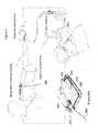
- FIG. 1Aillustrates a perspective view of an extravasation sensor according to a one embodiment of the present invention, showing antennae on a bottom surface thereof designed for contact with the skin of a patient and RF cable assemblies associated therewith.
- FIG. 1Bis a bottom view of the extravasation sensor shown in FIG. 1A .
- FIG. 1Cis a side view of the extravasation sensor shown in FIG. 1A , with the bottom surface thereof facing towards the bottom of the page.
- FIG. 1Dis a top view of the extravasation sensor shown in FIG. 1A .
- FIG. 1Eis an end view of the extravasation sensor shown in FIG. 1A , with the bottom surface thereof facing towards the bottom of the page.
- FIG. 2illustrates a generalized and idealized structural layout of the sensor of FIG. 1A , showing high sensitivity zones and an intermediate, reduced sensitivity zone.
- FIG. 3depicts an embodiment of a layout for a flexible circuit board, showing flexible striplines for use in conveying signals to and from the antennae of an extravasation sensor such as the one shown in FIG. 1A .
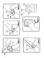
- FIG. 4illustrates a step-by-step procedure for using an attachment mechanism to attach an extravasation sensor of the present invention to the skin of a patient.
- FIG. 5illustrates an extravasation sensor attached to the patient via the attachment mechanism of FIG. 4 and its use within a control room of an imaging suite.
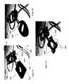
- FIG. 6Aillustrates an extravasation sensor according to the present invention including one or more indicators to provide a visual indication of extravasation
- FIG. 6Billustrates an extravasation sensor according to the present invention into which an arm button has been incorporated and which doubles as a visual indicator of extravasation.
- FIG. 6Cillustrates an extravasation sensor according to the present invention into which an indicator has been incorporated into each antenna element as a visual indicator of extravasation.
- FIG. 7illustrates a system for wirelessly transmitting a signal indicative of extravasation from an extravasation sensor (such as the one shown in FIG. 1A ) to a remote receiver.
- an extravasation sensorsuch as the one shown in FIG. 1A
- the sensors, systems and methods of the present inventionare generally applicable to the sensing any fluid within body tissue (whether a body fluid or an introduced fluid), the present invention is primarily described herein with reference to the representative example of extravasation of a fluid intended to be injected into a vascular structure.
- elevated, abnormal or changing levels of generally any fluidcan be detected using the sensors, systems and methods of the present invention.
- Detection of body fluids in the present inventionincludes, but is not limited to, the detection of fluid changes as a result of edema, hematoma, ruptured bowel and colostomy tubing leakage into the peritoneal cavity.
- Introduced or foreign fluid detectible in the present inventioninclude fluid introduced via generally any technique known in the medical arts including, but not limited to, injection, infusion and IV drip. As described above, changes in complex permittivity and permeability as a result of changing fluid levels in tissue are detected by application of electromagnetic energy to the tissue and detection of a resultant signal.
- Complex permittivity and permeabilitygovern how an electromagnetic wave will propagate through a substance.
- Complex permittivitytypically has the greatest effect since it varies significantly between tissue types and fluids of interest.
- the complex permeability of various tissues and many fluids of interestis approximately that of a vacuum, reducing the effect of this parameter.
- Some fluids, however, such as MRI contrast agentsmay have an appreciable complex permeability difference from tissue.
- ⁇ ′′is the imaginary component of the complex value and is often referred to as the “loss factor.”
- the ratio of ( ⁇ ′′/ ⁇ ′)is known as the “loss tangent.”
- the complex permittivity (and sometimes permeability) of certain substancesdiffer from the body tissue at certain frequencies. In the present invention, such differences in permittivity and/or permeability are used for the detection and level monitoring of certain fluids and substances in biological tissue.
- Electromagnetic energy in the frequency range set forth abovehas been found to transmit through the skin and to transmit or propagate well within, for example, fat. Good transmission through the fat layer is beneficial for detection of extravasation as many extravasations occur in the fat layer. The sensitivity to extravasation of the systems, devices and methods of the present invention is thus increased as compared, for example, to impedance plethysmography.
- FIG. 1A-1Eillustrate multiple views of one embodiment of an extravasation sensor 10 of the present invention.
- Extravasation sensor 10includes a housing 20 , a plurality of antenna or sensor elements 60 a , 60 b 60 c and 60 d , and the RF cable assemblies 100 associated therewith.
- Each of coaxial cables 100includes a subminiature coaxial connector (SMA connector) 110 .
- SMA connectorsubminiature coaxial connector
- the housing 20can, for example, be fabricated from a base material, such as urethane and/or silicone material.
- a ferromagnetic and/or other material suitable to absorb leakage of electromagnetic energycan be mixed into the base material.
- a carbonyl iron powdersuch as the EW grade carbonyl iron powder produced by the BASF Corporation, of Mount Olive, N.J., is suitable for this purpose.
- the ferromagnetic powderis mixed into the housing base material at least around the antenna elements and cables.
- leakagecould potentially cause artifacts to be induced within the signals conveyed from the antenna elements 30 as a result of, for example, palpation of the skin in the area of the extravasation sensor 10 or as a result of other movement of the sensor 10 .
- artifactscould also decrease the sensitivity of the sensor 10 to the presence of subcutaneous fluid. It is apparent that one can also mix the ferromagnetic material into a different base material (for example, a base material that will form a more rigid housing).
- housing 20 of the extravasation sensor 10defines an opening 24 between the antenna elements 60 a - d .
- Opening 24provides both visual and tactile (palpation) access to the site of interest where subcutaneous fluid will likely accumulate should extravasation occur. Opening 24 thus provides the operator with the option of checking for or confirming the presence of fluid merely by looking at or palpating the skin through opening 24 in housing 20 .
- Housing 20also includes segments 30 and 30 a that bridge the gap between seatings 40 (positioned at intersections 50 between connected segments 30 and 30 a ) in which antenna elements 60 a - d are seated.
- Bridge segments 30 and 30 aare, for example, low in profile to provide an operator access through opening 24 to the site of interest for the purpose of palpation. Nurses or technologists often position their hand in such a manner that low-profile bridge segments 30 and 30 a (particularly those bridge segments 30 a on the sides of sensor 10 ) allow improved ability to palpate the site of interest to check for extravasation.
- side bridge segments 30 acan be curved outwardly away from the center of the palpation area to allow increased accessibility.
- antenna elements 60 a - dinclude an active antenna or resonant structure 62 surrounded by a substrate 64 such as a ceramic material (for example, MgCaTiO 2 ).
- Resonant structures 62are, for example, adapted to transmit and receive electromagnetic energy in the frequency ranges set forth above.
- the substrate materialcan, for example, have a moderate to high dielectric constant (for example, in the range of approximately 5 to approximately 100 or in the range of approximately 50 to approximately 80) or high permittivity and low loss.
- a ceramic materialin the range of 5-15, thereby reducing manufacturing costs
- the impedance of substrate 64is preferably similar to that of the surface of the tissue to be studied.
- antenna elements 60 a - d of the present inventiondid not include a superstrate material.
- the antenna elementssuch as shown in FIG. 7D of each of those published U.S. patent applications were positioned atop or otherwise formed within a substrate and shielded from direct contact with the skin by use of a superstrate.
- antenna elements 60 a - dBy forming antenna elements 60 a - d without a superstrate, antenna element 60 a - d becomes electromagnetically loaded when adjacent to human tissue on which extravasation sensor 10 is positioned. This electromagnetic loading increases the bandwidth of extravasation sensor 10 , which increases its ability to detect subcutaneous pools of various shapes and sizes.
- Microstrip antennae 60 a through 60 d used in several studies of the present inventionwere fabricated from a ceramic laminate material coated with thin layers of copper on the front and back thereof.
- a ceramic laminate materialcoated with thin layers of copper on the front and back thereof.
- Such a materialis, for example, available from Rogers Corporation of Chandler, Ariz. under the product name RT/duroid® 6010LM.
- Such microwave laminatesare ceramic-PTFE composites designed for electronic and microwave circuit applications requiring a relatively high dielectric constant.
- RT/duroid 6010LM laminatehas a dielectric constant of approximately 10.2.
- the laminatewas approximately 2.5 mm thick and was supplied with both sides thereof clad with 1 ⁇ 4 to 2 oz./ft. 2 (8 to 70 ⁇ m) electrodeposited copper foil.
- antennaeor microstrip antennae 60 a - d of the present invention
- some of the copper materialwas etched from the top of the laminate to form generally planar antenna active element or resonant structure 62 , thereby forming a margin between the outer edge of resonant structure 62 and the outer edge of substrate 64 .
- the copper on the bottom side of the laminateformed ground plane 66 of antenna 62 a - d .
- Side shielding 68 of a conductive materialcan be provided to, for example, improve tissue coupling and prevent stray energy.
- Each antenna element 60 a through 60 dcan also include a conductive front lip 67 on the surface of the ceramic material to provide additional shielding. Coupled with the protection provided by the side shielding 68 , forward conductive lip 67 for each antenna elements 60 a - d serves to further decrease the leakage of stray electromagnetic energy.
- conductive lip 67was fabricated from a conductive material such as copper having a thickness of approximately 0.010 inches.
- sensor 10includes two antenna sets or pairs 70 a and 70 b .
- First antenna pair 70 aincludes first transmitting antenna element 60 a and first receiving antenna element 60 b .
- Second antenna pair 70 bincludes second transmitting antenna element 60 c and second receiving antenna element 60 d .
- the transmitting and receiving antenna elements of each of first antenna pair 70 a and second antenna pair 70 bare held in spaced connection by bridging segments 30 .
- the length of bridging segments 30and thus the space between the transmitting and receiving antenna elements, can be used to adjust the sensitivity of the antenna pair to fluid changes in the high sensitivity zone of the sensor (see, for example, FIG.
- FIG. 2illustrates a schematic structural layout for extravasation sensor 10 of the present invention, in which four antenna elements 60 a through 60 d are separated to form a first high sensitivity zone 80 a between antenna elements 60 a and 60 b and a second high sensitivity zone between antenna elements 60 c and 60 d .
- Between high sensitivity zones 80 a and 80 bis a region or zone 84 of lower or reduce sensitivity.
- the size of the reduced sensitivity zone 84 (and the sensitivity therein)is determined by the length of side bridging segments 30 a which operatively connect and space first antenna pair 70 a and second antenna pair 70 b .
- the spacing between antenna pairs 70 a and 70 beffectively increases the sensing range of extravasation sensor 10 .
- reduced sensitivity zone 84between antenna pairs 70 a and 70 b is achieved by spacing antenna pairs 70 a and 70 b .
- High sensitivity zones 80 a and 80 bare “primary” areas in which fluid build up can be detected with highest sensitivity.
- the formation of intermediate, reduced sensitivity zone 84allows a small, clinically insignificant amount of fluid (e.g., blood contrast agent, or saline) to collect before extravasation sensor 10 indicates a positive response.
- This configurationcan be particularly desirable in, for example, the computerized tomography (CT) setting wherein extravasation of a small amount of fluid happens in a percentage of procedures and does not require the termination of the CT examination.
- CTcomputerized tomography
- sensor 10can be positioned so that the tip of the injection catheter is placed within reduced sensitivity zone 84 (for example, positioned generally centrally within reduced sensitivity zone 84 or within open area 24 ).
- reduced sensitivity zone 84allows small, clinically insignificant, extravasation (blood and/or contrast agent) volumes to accumulate while significantly reducing the probability of a false positive alarm. Indeed, in several clinical studies of the present invention, false positive alarms were maintained below 0.1% while a positive extravasation detection rate in excess of 95% was achieved.
- reduced sensitivity zone 84is located between high sensitivity zones or sensing areas 80 a and 80 b .
- Increased fluid levels in low sensitivity region 84can cause tissue distortion in one or both of high sensitivity zones 80 a and 80 b , and indirectly cause some level of sensor response. Because of such effective overlap of high sensitivity zones 80 a and 80 b and intermediate, reduced sensitivity zone 84 , the overall fluid volume sensing range of sensor 10 is increased significantly.
- housing 20In addition to maintaining a predetermined, desired spacing between the antenna elements of each antenna element pair and a predetermined, desired spacing between the antenna element pairs, housing 20 also maintains a desired relative orientation between the antenna elements of each antenna element pair and between the antenna element pairs. Also, housing 20 assists in assuring that each of antenna elements 60 a - d is generally coplanar when sensor device 10 is in operative connection with a patient's skin.
- FIG. 3illustrates an embodiment of use of a flexible circuit board (also referred to as a “RF flex circuit board”) to create a unique thin, “flexible strip” or flexible circuit transmission system 200 that can be used to carry and distribute the electromagnetic (for example, microwave) signals being transmitted from and received by extravasation sensor 300 .
- Sensor 300includes antenna elements 360 a - d which operate in a manner as described above in connection with antenna elements 60 a - d.
- Flexible strip transmission system 200includes transmission lines or traces 210 .
- the flexible strip transmission system 200is provided with “side vias” 220 which (in connection with conductive layers laminated on the major surfaces of the flexible strip) complete a shielded, fall coaxial structure for use in carrying microwave signals to and from antenna elements 360 a - d of sensor 300 .
- top and bottom conductive layers of flexible strip transmission system 200serve as ground planes, while vias between those layers are used to provide side shielding.
- traces 210can, for example, include splitting and combining geometries 212 to split the energy between multiple transmitting antenna elements such as antenna elements 260 a and 260 c and to combine energy from multiple receiving antenna elements such as antenna elements 260 b and 260 d if desired. This splitting and combining allows the use of fewer cables when connecting sensor 300 to processing circuitry. Flex circuit boards and other materials suitable for use at microwave frequencies are commercially available from, for example, DuPont and the Advanced Circuit Materials Division of Rogers Corporation, of Chandler, Ariz.
- a further advantage of the use of flex circuit board in connection with an energy transmission system of the sensors of the present inventionis that a low-profile connection to the antennas elements can be achieved.
- Use of coaxial cables which are soldered to the antennas elements of the present inventioncan require a sizeable bending radius, creating a higher profile connection.
- RF flex circuitincludes an RF vertical transition including a center signal via surrounded by ground/reference vias completing a coaxial structure to transmit/receive microwave energy to and from the antennas elements.
- the antenna elementscan, for example, be wave soldered in an automated process directly to the thin RF flex circuit without use of additional connectors or cables, achieving a low-profile connection.
- FIG. 4illustrates one embodiment of a step-by-step procedure for using an attachment mechanism 400 of the present invention to attach an extravasation sensor 450 of the present invention to the skin of a patient.
- attachment mechanism 400includes a double-sided adhesive portion 410 and a release band 420 (which preferably includes no adhesive) around the perimeter of adhesive portion 410 .
- adhesive portion 410defines a cutout region 430 .
- Cutout region 430can be shaped in the shape of an arrow (pointing, for example, in the direction of contrast medium flow) or other shape to indicate a preferred orientation for attachment.
- double-sided adhesive portion 410is designed to attach to the skin of the patient over the site or region of interest (typically centralized on the tip of the catheter), and the opposite side is designed to permit extravasation sensor 450 to be affixed thereto.
- cutout region 430 of adhesive portion 420 and an opening 470 of extravasation sensor 450are generally coextensive, thereby allowing the operator visual and tactile (palpation) access to the site of interest.
- a first stepan operator removes a first cover film or layer 412 from the side of double-sided adhesive portion 410 including the adhesive adapted to attach to the patient's skin.
- attachment mechanism 400is attached to the patient skin with the arrow of cutout portion 430 pointing in the direction of the contrast medium flow.
- a second cover film or layer 414is removed from the side of double-sided adhesive portion 410 including the adhesive adapted to attach sensor 450 to attachment mechanism 400 .
- sensor 450is attached to the attachment mechanism 400 so that open area 470 of sensor 450 is in general alignment with cutout region 430 .
- the sensing moduleis armed.
- release band 420 of attachment mechanism 400enables the operator to pull attachment mechanism 400 off the skin after use of extravasation sensor 450 is complete.
- the color, material or texture of adhesive portion 410 and release band 420can be different. This difference facilitates the positioning and secure attachment of extravasation sensor 450 .
- Each side of attachment mechanism 400can have a different level of adhesion (i.e., aggressiveness of adhesive) which facilitates the tailoring of the adhesion to the skin side which may be less than that of the sensor side.
- 3M Medical Double Coated Tape #1512available from 3M of Saint Paul, Minn. was used.
- This tapeis fabricated from a hypoallergenic polyethylene material.
- the double-sided adhesive tapepreferably maintains sufficient contact with the skin and (upon proper use) provides resistance to wrinkling and formation of air pockets upon placement.
- the double-sided adhesive tape materialpreferably has a low electromagnetic loss factor (that is, in the sensor's operating frequency range). Such properties allow the electromagnetic energy (for example, microwaves) to penetrate the adhesive tape effectively. Most adhesive tapes possess these characteristics. Tapes that contain metallic particles or other conductive materials, however, may not be suitable for use in the attachment mechanisms of the present invention.
- the tapecan, however, contain, for example, a material such as a ceramic material that yields a thin structure with low electromagnetic loss and an impedance that matches the surface tissue.
- This embodimentcan provide better coupling of the microwave energy between the antennas and the tissue to increase detection sensitivity while decreasing leaked energy and thereby decreasing any palpation/motion artifact.
- the inner or patient side cover film 412is the removed and the attachment mechanism/sensor assembly is placed against the skin, briefly applying pressure.
- opening 470 for palpation in the housing of extravasation sensor 400 as well as the cutout region of the attachment mechanismcan be formed to indicate the direction to which the sensor should be placed (e.g., arrow shaped). This shape of opening 470 also helps the operator to align extravasation sensor 450 and attachment mechanism 400 for optimal attachment to a patient's skin, which is important for integrity of the signals detected and conveyed by extravasation sensor 400 .
- Extravasation sensor 450 and other extravasation sensors of the present inventioncan also be equipped with one or more user interfaces or indicator.
- FIGS. 6A and 6Brespectively, illustrate that a light pipe 480 or other visual indicators, such as light-emitting diodes 580 (LEDs) on sensor 500 , can be incorporated into the extravasation sensors of the present invention to provide, for example, a visual indication of extravasation. Additional or alternatively, other types of indicators such as audible indicators or tactile indicators can be provided.
- a light pipe 480is incorporated into the RF cable assembly that interconnects the extravasation sensor and its associated base/control unit so that the entire cable or a portion thereof lights to indicate a positive extravasation state.
- a light pipecan also pass through the cabling to light an indicator on the housing of the sensor.
- a plurality of indicator lights 580are provided.
- a user input button for functions such as “arming” or “baselining” the overall systemcan be implemented at the extravasation sensor of the present invention.
- indicator 580is also a user input button.
- An audible, tactile and/or visual alarmcan also be integrated within the housing of the sensor.
- An indicator devicesuch as indicator light 480 ′ can alternatively or additionally be mounted to or otherwise integrated into a remote display or controller unit for the injector system, as, for example, illustrated in FIG. 5 in the context of a CT imaging suite.
- a remote display or control unitis typically located in the control room of a CT suite rather than in the scanner room where the injector and extravasation sensor will be sited.
- FIG. 7illustrates a system 700 for wirelessly transmitting a signal indicative of extravasation from an extravasation sensor 800 outfitted with a transmitter 710 (for example, an RF transmitter) to a remote receiver 720 .
- a wireless system 700can be implemented with any extravasation sensor of the present invention.
- wireless system 700includes a short RF cable 730 connecting sensor 800 to transmitter 710 .
- extravasation sensor 800can be attached to, for example, the upper arm about the site of the injection and transmitter 710 can be strapped or otherwise attached near or directly to the wrist. If extravasation sensor 800 is attached to the back of the hand or wrist, RF transmitter 710 can then be strapped to the upper arm much like a sports radio.
- Short RF cable 730interconnects the two components as described above, and can be either a distinct component or emanate from the housing of sensor 800 .
- Short RF cable 730 in this configurationcan improve performance and decrease the potential of motion artifacts and other complications that may be associated with certain longer cables.
- sensor 800includes a palpation opening 840 and indicator lights 880 which operate as described above.
- PETpositron emission tomography
- MRImagnetic resonance imaging
- MRAmagnetic resonance angiography
- ultrasound proceduresas well as a wide variety of therapeutic and other procedures.
Landscapes
- Health & Medical Sciences (AREA)
- Life Sciences & Earth Sciences (AREA)
- Engineering & Computer Science (AREA)
- Biomedical Technology (AREA)
- Heart & Thoracic Surgery (AREA)
- Veterinary Medicine (AREA)
- Public Health (AREA)
- General Health & Medical Sciences (AREA)
- Animal Behavior & Ethology (AREA)
- Surgery (AREA)
- Medical Informatics (AREA)
- Molecular Biology (AREA)
- Pathology (AREA)
- Biophysics (AREA)
- Physics & Mathematics (AREA)
- Radiology & Medical Imaging (AREA)
- Nuclear Medicine, Radiotherapy & Molecular Imaging (AREA)
- Vascular Medicine (AREA)
- Physiology (AREA)
- Computer Networks & Wireless Communication (AREA)
- Immunology (AREA)
- Anesthesiology (AREA)
- Hematology (AREA)
- Measuring And Recording Apparatus For Diagnosis (AREA)
- Measuring Pulse, Heart Rate, Blood Pressure Or Blood Flow (AREA)
- Arrangements For Transmission Of Measured Signals (AREA)
- Investigating Or Analyzing Materials By The Use Of Electric Means (AREA)
Abstract
Description
∈*=∈′−j∈″
wherein ∈′ is the real component of the complex value and is known as the dielectric constant or sometimes simply referred to as the “permittivity.” The term ∈″ is the imaginary component of the complex value and is often referred to as the “loss factor.” The ratio of (∈″/∈′) is known as the “loss tangent.” The complex permittivity (and sometimes permeability) of certain substances differ from the body tissue at certain frequencies. In the present invention, such differences in permittivity and/or permeability are used for the detection and level monitoring of certain fluids and substances in biological tissue.
Claims (19)
Priority Applications (1)
| Application Number | Priority Date | Filing Date | Title |
|---|---|---|---|
| US10/576,333US8295920B2 (en) | 2003-10-24 | 2004-10-25 | System for detecting fluid changes and sensoring devices therefor |
Applications Claiming Priority (3)
| Application Number | Priority Date | Filing Date | Title |
|---|---|---|---|
| US51435503P | 2003-10-24 | 2003-10-24 | |
| PCT/US2004/035135WO2005043100A2 (en) | 2003-10-24 | 2004-10-25 | Systems for detecting fluid changes and sensor devices therefor |
| US10/576,333US8295920B2 (en) | 2003-10-24 | 2004-10-25 | System for detecting fluid changes and sensoring devices therefor |
Publications (2)
| Publication Number | Publication Date |
|---|---|
| US20070123770A1 US20070123770A1 (en) | 2007-05-31 |
| US8295920B2true US8295920B2 (en) | 2012-10-23 |
Family
ID=34549328
Family Applications (2)
| Application Number | Title | Priority Date | Filing Date |
|---|---|---|---|
| US10/576,333Active2029-04-11US8295920B2 (en) | 2003-10-24 | 2004-10-25 | System for detecting fluid changes and sensoring devices therefor |
| US13/620,310AbandonedUS20130274599A1 (en) | 2003-10-24 | 2012-09-14 | Systems for detecting fluid changes and sensor devices therefor |
Family Applications After (1)
| Application Number | Title | Priority Date | Filing Date |
|---|---|---|---|
| US13/620,310AbandonedUS20130274599A1 (en) | 2003-10-24 | 2012-09-14 | Systems for detecting fluid changes and sensor devices therefor |
Country Status (5)
| Country | Link |
|---|---|
| US (2) | US8295920B2 (en) |
| EP (2) | EP1675506B1 (en) |
| JP (1) | JP4511549B2 (en) |
| CN (1) | CN100482151C (en) |
| WO (1) | WO2005043100A2 (en) |
Cited By (44)
| Publication number | Priority date | Publication date | Assignee | Title |
|---|---|---|---|---|
| US20110130800A1 (en)* | 2009-12-01 | 2011-06-02 | Kyma Medical Technologies Ltd | Microwave Monitoring of Heart Function |
| US20140375335A1 (en)* | 2011-08-26 | 2014-12-25 | Spectral Labs Incorporated | Handheld multisensor contraband detector to improve inspection of personnel at checkpoints |
| US9161717B2 (en) | 2011-09-23 | 2015-10-20 | Orthosensor Inc. | Orthopedic insert measuring system having a sealed cavity |
| US9220420B2 (en) | 2010-07-21 | 2015-12-29 | Kyma Medical Technologies Ltd. | Implantable dielectrometer |
| US9226694B2 (en) | 2009-06-30 | 2016-01-05 | Orthosensor Inc | Small form factor medical sensor structure and method therefor |
| US9259179B2 (en) | 2012-02-27 | 2016-02-16 | Orthosensor Inc. | Prosthetic knee joint measurement system including energy harvesting and method therefor |
| US9259172B2 (en) | 2013-03-18 | 2016-02-16 | Orthosensor Inc. | Method of providing feedback to an orthopedic alignment system |
| US9265438B2 (en) | 2008-05-27 | 2016-02-23 | Kyma Medical Technologies Ltd. | Locating features in the heart using radio frequency imaging |
| US9271675B2 (en) | 2012-02-27 | 2016-03-01 | Orthosensor Inc. | Muscular-skeletal joint stability detection and method therefor |
| US9289163B2 (en) | 2009-06-30 | 2016-03-22 | Orthosensor Inc. | Prosthetic component for monitoring synovial fluid and method |
| US9289550B1 (en) | 2001-02-06 | 2016-03-22 | Bayer Healthcare Llc | Apparatus and method for detecting fluid extravasation |
| US9326686B2 (en) | 2012-03-12 | 2016-05-03 | Ivwatch, Llc | System and method for mitigating the effects of tissue blood volume changes to aid in diagnosing infiltration or extravasation in animalia tissue |
| US9345449B2 (en) | 2009-06-30 | 2016-05-24 | Orthosensor Inc | Prosthetic component for monitoring joint health |
| US9345492B2 (en) | 2009-06-30 | 2016-05-24 | Orthosensor Inc. | Shielded capacitor sensor system for medical applications and method |
| US9357964B2 (en) | 2009-06-30 | 2016-06-07 | Orthosensor Inc. | Hermetically sealed prosthetic component and method therefor |
| US9402583B2 (en) | 2009-06-30 | 2016-08-02 | Orthosensor Inc. | Orthopedic screw for measuring a parameter of the muscular-skeletal system |
| US9414940B2 (en) | 2011-09-23 | 2016-08-16 | Orthosensor Inc. | Sensored head for a measurement tool for the muscular-skeletal system |
| US9462964B2 (en) | 2011-09-23 | 2016-10-11 | Orthosensor Inc | Small form factor muscular-skeletal parameter measurement system |
| US9492115B2 (en) | 2009-06-30 | 2016-11-15 | Orthosensor Inc. | Sensored prosthetic component and method |
| US9622701B2 (en) | 2012-02-27 | 2017-04-18 | Orthosensor Inc | Muscular-skeletal joint stability detection and method therefor |
| US9757051B2 (en) | 2012-11-09 | 2017-09-12 | Orthosensor Inc. | Muscular-skeletal tracking system and method |
| US9839374B2 (en) | 2011-09-23 | 2017-12-12 | Orthosensor Inc. | System and method for vertebral load and location sensing |
| US9839390B2 (en) | 2009-06-30 | 2017-12-12 | Orthosensor Inc. | Prosthetic component having a compliant surface |
| US9844335B2 (en) | 2012-02-27 | 2017-12-19 | Orthosensor Inc | Measurement device for the muscular-skeletal system having load distribution plates |
| US9937062B2 (en) | 2011-09-23 | 2018-04-10 | Orthosensor Inc | Device and method for enabling an orthopedic tool for parameter measurement |
| US10052064B2 (en) | 2013-04-04 | 2018-08-21 | Thermal Technologies, Inc. | Edema monitor |
| US10548485B2 (en) | 2015-01-12 | 2020-02-04 | Zoll Medical Israel Ltd. | Systems, apparatuses and methods for radio frequency-based attachment sensing |
| US10663411B2 (en) | 2014-03-21 | 2020-05-26 | Battelle Memorial Institute | Liquid scanning system and method for IV drug verification and identification |
| US10680324B2 (en) | 2013-10-29 | 2020-06-09 | Zoll Medical Israel Ltd. | Antenna systems and devices and methods of manufacture thereof |
| US10724968B2 (en) | 2014-03-21 | 2020-07-28 | Battelle Memorial Institute | System and method for solution constituent and concentration identification |
| US10722136B2 (en) | 2011-09-02 | 2020-07-28 | Battelle Memorial Institute | Wireless and power-source-free extravasation and infiltration detection sensor |
| US10746716B1 (en) | 2019-05-31 | 2020-08-18 | Battelle Memorial Institute | System and method for solution constituent and concentration identification |
| US10842432B2 (en) | 2017-09-14 | 2020-11-24 | Orthosensor Inc. | Medial-lateral insert sensing system with common module and method therefor |
| US11013420B2 (en) | 2014-02-05 | 2021-05-25 | Zoll Medical Israel Ltd. | Systems, apparatuses and methods for determining blood pressure |
| US11020002B2 (en) | 2017-08-10 | 2021-06-01 | Zoll Medical Israel Ltd. | Systems, devices and methods for physiological monitoring of patients |
| US11259715B2 (en) | 2014-09-08 | 2022-03-01 | Zoll Medical Israel Ltd. | Monitoring and diagnostics systems and methods |
| US11793424B2 (en) | 2013-03-18 | 2023-10-24 | Orthosensor, Inc. | Kinetic assessment and alignment of the muscular-skeletal system and method therefor |
| US11812978B2 (en) | 2019-10-15 | 2023-11-14 | Orthosensor Inc. | Knee balancing system using patient specific instruments |
| WO2023205697A3 (en)* | 2022-04-19 | 2023-11-30 | The Johns Hopkins University | Device for early detection of pediatric iv infiltration |
| US11896352B2 (en) | 2020-04-30 | 2024-02-13 | Bayer Healthcare Llc | System, device and method for safeguarding the wellbeing of patients for fluid injection |
| US12208239B2 (en) | 2018-08-28 | 2025-01-28 | Bayer Healthcare Llc | Fluid injector system, method of preventing fluid backflow, and computer program product |
| US12214155B2 (en) | 2017-08-31 | 2025-02-04 | Bayer Healthcare Llc | Fluid injector system volume compensation system and method |
| US12251544B2 (en) | 2018-04-19 | 2025-03-18 | Bayer Healthcare Llc | System and method for air detection in fluid injector |
| US12427249B2 (en) | 2018-08-28 | 2025-09-30 | Bayer Healthcare Llc | Fluid injector system with improved ratio performance |
Families Citing this family (23)
| Publication number | Priority date | Publication date | Assignee | Title |
|---|---|---|---|---|
| US20060211970A1 (en)* | 2005-03-16 | 2006-09-21 | Sciulli Frank J | Releasable application systems and releasable medical device systems |
| CN101217945B (en) | 2005-05-20 | 2012-07-11 | 陶氏环球技术有限责任公司 | Oral drug compliance monitoring using radio frequency identification tags |
| CN101466306B (en)* | 2006-04-19 | 2013-09-11 | 阿西斯特医疗系统有限公司 | Extravasation detection device |
| US7674244B2 (en) | 2006-05-23 | 2010-03-09 | Medrad, Inc. | Devices, systems and methods for detecting increase fluid levels in tissue |
| ES2664239T3 (en) | 2007-09-05 | 2018-04-18 | Sensible Medical Innovations Ltd. | Method and apparatus for using electromagnetic radiation to monitor a user's tissue |
| US10667715B2 (en) | 2008-08-20 | 2020-06-02 | Sensible Medical Innovations Ltd. | Methods and devices of cardiac tissue monitoring and analysis |
| EP2403401B1 (en) | 2009-03-04 | 2017-05-10 | Sensible Medical Innovations Ltd. | System for monitoring intrabody tissues |
| US8907682B2 (en)* | 2009-07-30 | 2014-12-09 | Sensible Medical Innovations Ltd. | System and method for calibration of measurements of interacted EM signals in real time |
| US20110103193A1 (en)* | 2009-11-02 | 2011-05-05 | Denis Jimenez | Personal Alert System with Adhesive Fixation |
| CN103281952B (en)* | 2010-11-03 | 2015-09-23 | 合理医疗创新有限公司 | Electromagnetic probe and its manufacture method and the system using this kind of Electromagnetic probe |
| EP2457507B1 (en)* | 2010-11-24 | 2020-01-01 | eesy-innovation GmbH | Arm band with a recording device for recording a blood count parameter |
| EP2861132B1 (en)* | 2012-06-13 | 2020-11-18 | Dean Nahman | Devices for detection of internal bleeding and hematoma |
| US9526438B2 (en)* | 2013-04-26 | 2016-12-27 | University Of Hawaii | Microwave stethoscope for measuring cardio-pulmonary vital signs and lung water content |
| US10062958B2 (en)* | 2014-11-21 | 2018-08-28 | Qualcomm Incorporated | Wearable electronic patch with antenna enhancement |
| US10384002B2 (en)* | 2015-01-30 | 2019-08-20 | Mackay Memorial Hospital | Sensor patch, system, and method for detecting fluid leakage |
| TWI573571B (en)* | 2015-01-30 | 2017-03-11 | 台灣基督長老教會馬偕醫療財團法人馬偕紀念醫院 | Sensor patch, system, and method for detecting fluid leakage |
| US10856806B2 (en) | 2015-02-12 | 2020-12-08 | University Of Hawaii | Lung water content measurement system and calibration method |
| US11154246B2 (en) | 2016-06-24 | 2021-10-26 | Georgia Tech Research Corporation | Systems and methods of IV infiltration detection |
| US12263326B2 (en) | 2016-11-14 | 2025-04-01 | Bayer Healthcare Llc | Methods and systems for verifying the contents of a syringe used for medical fluid delivery |
| EP3381370B1 (en)* | 2017-03-31 | 2019-11-20 | RichHealth Technology Corporation | Transdermal microneedle array patch |
| US11099680B2 (en)* | 2018-01-19 | 2021-08-24 | Tactual Labs Co. | Matrix sensor with receive isolation |
| WO2021127501A1 (en)* | 2019-12-19 | 2021-06-24 | Qorvo Us, Inc. | Coaxial connector |
| US20220346661A1 (en)* | 2021-04-29 | 2022-11-03 | Know Labs, Inc. | Antenna array for a non-invasive analyte sensor |
Citations (23)
| Publication number | Priority date | Publication date | Assignee | Title |
|---|---|---|---|---|
| US4240445A (en) | 1978-10-23 | 1980-12-23 | University Of Utah | Electromagnetic energy coupler/receiver apparatus and method |
| US4488559A (en) | 1981-06-30 | 1984-12-18 | University Of Utah | Apparatus and method for measuring lung water content |
| US4647281A (en) | 1985-02-20 | 1987-03-03 | M/A-Com, Inc. | Infiltration detection apparatus |
| US4690149A (en) | 1985-10-28 | 1987-09-01 | The Johns Hopkins University | Non-invasive electromagnetic technique for monitoring physiological changes in the brain |
| US4877034A (en) | 1987-06-18 | 1989-10-31 | Smith & Nephew, Inc. | Method and device for detection of tissue infiltration |
| US5184620A (en)* | 1991-12-26 | 1993-02-09 | Marquette Electronics, Inc. | Method of using a multiple electrode pad assembly |
| US5334141A (en) | 1992-06-26 | 1994-08-02 | Medrad, Inc. | Extravasation detection system and apparatus |
| US5947910A (en) | 1994-01-14 | 1999-09-07 | E-Z-Em, Inc. | Extravasation detection technique |
| US5954668A (en) | 1996-06-14 | 1999-09-21 | Medrad, Inc. | Extravasation detector using microwave radiometry |
| US5964703A (en) | 1994-01-14 | 1999-10-12 | E-Z-Em, Inc. | Extravasation detection electrode patch |
| US5995863A (en) | 1996-12-27 | 1999-11-30 | Instituto Trentino Di Cultura | Method and an automatic system for obtaining water content and electric-permittivity maps from magnetic resonance images |
| US6026173A (en) | 1997-07-05 | 2000-02-15 | Svenson; Robert H. | Electromagnetic imaging and therapeutic (EMIT) systems |
| US6047215A (en) | 1998-03-06 | 2000-04-04 | Sonique Surgical Systems, Inc. | Method and apparatus for electromagnetically assisted liposuction |
| US6061589A (en) | 1994-07-01 | 2000-05-09 | Interstitial, Inc. | Microwave antenna for cancer detection system |
| US6233479B1 (en) | 1998-09-15 | 2001-05-15 | The Regents Of The University Of California | Microwave hematoma detector |
| US6263226B1 (en) | 1998-02-09 | 2001-07-17 | Axelgaard Manufacturing Co., Ltd. | Sponge electrode |
| US6300906B1 (en) | 2000-01-05 | 2001-10-09 | Harris Corporation | Wideband phased array antenna employing increased packaging density laminate structure containing feed network, balun and power divider circuitry |
| US6408204B1 (en)* | 1999-07-28 | 2002-06-18 | Medrad, Inc. | Apparatuses and methods for extravasation detection |
| US6415170B1 (en) | 1996-12-09 | 2002-07-02 | 3M Innovative Properties Company | Biomedical electrode and method for its manufacture |
| US6487428B1 (en)* | 2000-08-31 | 2002-11-26 | Trustees Of The University Of Pennsylvania | Extravasation detection apparatus and method based on optical sensing |
| WO2003009753A2 (en) | 2001-07-26 | 2003-02-06 | Chad Bouton | Detection of fluids in tissue |
| US20030036674A1 (en) | 2001-07-26 | 2003-02-20 | Bouton Chad Edward | Electromagnetic sensors for biological tissue applications and methods for their use |
| WO2003063680A2 (en) | 2002-01-25 | 2003-08-07 | Inotech Medical Systems, Inc. | Tissue monitoring system for intravascular infusion |
Family Cites Families (5)
| Publication number | Priority date | Publication date | Assignee | Title |
|---|---|---|---|---|
| US3618602A (en)* | 1969-08-28 | 1971-11-09 | Robert F Shaw | Liquid infusion infiltration detection apparatus and method |
| JPH0579468U (en)* | 1992-03-27 | 1993-10-29 | 株式会社潤工社 | Leak detection device |
| US20010044588A1 (en)* | 1996-02-22 | 2001-11-22 | Mault James R. | Monitoring system |
| JPH1157001A (en)* | 1997-08-11 | 1999-03-02 | Suugan Kk | Extravascular administration detector |
| ITBO20010110A1 (en)* | 2001-03-01 | 2002-09-01 | Tre Esse Progettazione Biomedi | PROCEDURE AND IMPLANTABLE DEVICE FOR THE INTRA-PULMONARY MEASUREMENT OF PHYSICAL PROPERTIES OF THE PULMONARY FABRIC DEPENDENT ON ITS DENSIT |
- 2004
- 2004-10-25EPEP04796177.6Apatent/EP1675506B1/ennot_activeExpired - Lifetime
- 2004-10-25USUS10/576,333patent/US8295920B2/enactiveActive
- 2004-10-25CNCN200480031430.4Apatent/CN100482151C/ennot_activeExpired - Lifetime
- 2004-10-25EPEP12005361.6Apatent/EP2526857B1/ennot_activeExpired - Lifetime
- 2004-10-25JPJP2006536843Apatent/JP4511549B2/ennot_activeExpired - Lifetime
- 2004-10-25WOPCT/US2004/035135patent/WO2005043100A2/enactiveApplication Filing
- 2012
- 2012-09-14USUS13/620,310patent/US20130274599A1/ennot_activeAbandoned
Patent Citations (27)
| Publication number | Priority date | Publication date | Assignee | Title |
|---|---|---|---|---|
| US4240445A (en) | 1978-10-23 | 1980-12-23 | University Of Utah | Electromagnetic energy coupler/receiver apparatus and method |
| US4488559A (en) | 1981-06-30 | 1984-12-18 | University Of Utah | Apparatus and method for measuring lung water content |
| US4647281A (en) | 1985-02-20 | 1987-03-03 | M/A-Com, Inc. | Infiltration detection apparatus |
| US4690149A (en) | 1985-10-28 | 1987-09-01 | The Johns Hopkins University | Non-invasive electromagnetic technique for monitoring physiological changes in the brain |
| US4877034A (en) | 1987-06-18 | 1989-10-31 | Smith & Nephew, Inc. | Method and device for detection of tissue infiltration |
| US5184620A (en)* | 1991-12-26 | 1993-02-09 | Marquette Electronics, Inc. | Method of using a multiple electrode pad assembly |
| US5334141A (en) | 1992-06-26 | 1994-08-02 | Medrad, Inc. | Extravasation detection system and apparatus |
| US5947910A (en) | 1994-01-14 | 1999-09-07 | E-Z-Em, Inc. | Extravasation detection technique |
| US5964703A (en) | 1994-01-14 | 1999-10-12 | E-Z-Em, Inc. | Extravasation detection electrode patch |
| US6061589A (en) | 1994-07-01 | 2000-05-09 | Interstitial, Inc. | Microwave antenna for cancer detection system |
| US5954668A (en) | 1996-06-14 | 1999-09-21 | Medrad, Inc. | Extravasation detector using microwave radiometry |
| US6332087B1 (en) | 1996-07-05 | 2001-12-18 | The Carolinas Heart Institute | Electromagnetic imaging and therapeutic (EMIT) systems |
| US6415170B1 (en) | 1996-12-09 | 2002-07-02 | 3M Innovative Properties Company | Biomedical electrode and method for its manufacture |
| US5995863A (en) | 1996-12-27 | 1999-11-30 | Instituto Trentino Di Cultura | Method and an automatic system for obtaining water content and electric-permittivity maps from magnetic resonance images |
| US6026173A (en) | 1997-07-05 | 2000-02-15 | Svenson; Robert H. | Electromagnetic imaging and therapeutic (EMIT) systems |
| US6263226B1 (en) | 1998-02-09 | 2001-07-17 | Axelgaard Manufacturing Co., Ltd. | Sponge electrode |
| US6047215A (en) | 1998-03-06 | 2000-04-04 | Sonique Surgical Systems, Inc. | Method and apparatus for electromagnetically assisted liposuction |
| US6233479B1 (en) | 1998-09-15 | 2001-05-15 | The Regents Of The University Of California | Microwave hematoma detector |
| US6408204B1 (en)* | 1999-07-28 | 2002-06-18 | Medrad, Inc. | Apparatuses and methods for extravasation detection |
| US20030004433A1 (en) | 1999-07-28 | 2003-01-02 | Hirschman Alan D. | Apparatuses and methods for extravasation detection |
| US6300906B1 (en) | 2000-01-05 | 2001-10-09 | Harris Corporation | Wideband phased array antenna employing increased packaging density laminate structure containing feed network, balun and power divider circuitry |
| US6487428B1 (en)* | 2000-08-31 | 2002-11-26 | Trustees Of The University Of Pennsylvania | Extravasation detection apparatus and method based on optical sensing |
| WO2003009753A2 (en) | 2001-07-26 | 2003-02-06 | Chad Bouton | Detection of fluids in tissue |
| US20030036713A1 (en) | 2001-07-26 | 2003-02-20 | Chad Bouton | Detection of fluids in tissue |
| US20030036674A1 (en) | 2001-07-26 | 2003-02-20 | Bouton Chad Edward | Electromagnetic sensors for biological tissue applications and methods for their use |
| US7122012B2 (en) | 2001-07-26 | 2006-10-17 | Medrad, Inc. | Detection of fluids in tissue |
| WO2003063680A2 (en) | 2002-01-25 | 2003-08-07 | Inotech Medical Systems, Inc. | Tissue monitoring system for intravascular infusion |
Non-Patent Citations (3)
| Title |
|---|
| Birnbaum et al.,"Extravasation Detection Accessory: Clinical Evaluation in 500 Patients," Radiology (1999;212:431-438.). |
| Kent, M., "Hand Held Instrument for Fat/Water Determination in Whole Fish" (1993) at http://www.distell.com/index.php?exe=products:fish%20fat%20meter:research%20paper. |
| Supplementary European Search Report, May 26, 2010. |
Cited By (81)
| Publication number | Priority date | Publication date | Assignee | Title |
|---|---|---|---|---|
| US9289550B1 (en) | 2001-02-06 | 2016-03-22 | Bayer Healthcare Llc | Apparatus and method for detecting fluid extravasation |
| US9265438B2 (en) | 2008-05-27 | 2016-02-23 | Kyma Medical Technologies Ltd. | Locating features in the heart using radio frequency imaging |
| US10588599B2 (en) | 2008-05-27 | 2020-03-17 | Zoll Medical Israel Ltd. | Methods and systems for determining fluid content of tissue |
| US9492115B2 (en) | 2009-06-30 | 2016-11-15 | Orthosensor Inc. | Sensored prosthetic component and method |
| US9402583B2 (en) | 2009-06-30 | 2016-08-02 | Orthosensor Inc. | Orthopedic screw for measuring a parameter of the muscular-skeletal system |
| US9226694B2 (en) | 2009-06-30 | 2016-01-05 | Orthosensor Inc | Small form factor medical sensor structure and method therefor |
| US9839390B2 (en) | 2009-06-30 | 2017-12-12 | Orthosensor Inc. | Prosthetic component having a compliant surface |
| US9492116B2 (en) | 2009-06-30 | 2016-11-15 | Orthosensor Inc. | Prosthetic knee joint measurement system including energy harvesting and method therefor |
| US9357964B2 (en) | 2009-06-30 | 2016-06-07 | Orthosensor Inc. | Hermetically sealed prosthetic component and method therefor |
| US9358136B2 (en) | 2009-06-30 | 2016-06-07 | Orthosensor Inc. | Shielded capacitor sensor system for medical applications and method |
| US9345492B2 (en) | 2009-06-30 | 2016-05-24 | Orthosensor Inc. | Shielded capacitor sensor system for medical applications and method |
| US9289163B2 (en) | 2009-06-30 | 2016-03-22 | Orthosensor Inc. | Prosthetic component for monitoring synovial fluid and method |
| US9345449B2 (en) | 2009-06-30 | 2016-05-24 | Orthosensor Inc | Prosthetic component for monitoring joint health |
| US10660609B2 (en) | 2009-12-01 | 2020-05-26 | Zoll Medical Israel Ltd. | Methods and systems for determining fluid content of tissue |
| US9572512B2 (en) | 2009-12-01 | 2017-02-21 | Kyma Medical Technologies Ltd. | Methods and systems for determining fluid content of tissue |
| US8989837B2 (en) | 2009-12-01 | 2015-03-24 | Kyma Medical Technologies Ltd. | Methods and systems for determining fluid content of tissue |
| US12064284B2 (en) | 2009-12-01 | 2024-08-20 | Zoll Medical Israel Ltd. | Methods and systems for determining fluid content of tissue |
| US20110130800A1 (en)* | 2009-12-01 | 2011-06-02 | Kyma Medical Technologies Ltd | Microwave Monitoring of Heart Function |
| US11471127B2 (en) | 2009-12-01 | 2022-10-18 | Zoll Medical Israel Ltd. | Methods and systems for determining fluid content of tissue |
| US9220420B2 (en) | 2010-07-21 | 2015-12-29 | Kyma Medical Technologies Ltd. | Implantable dielectrometer |
| US9788752B2 (en) | 2010-07-21 | 2017-10-17 | Zoll Medical Israel Ltd. | Implantable dielectrometer |
| US10136833B2 (en) | 2010-07-21 | 2018-11-27 | Zoll Medical Israel, Ltd. | Implantable radio-frequency sensor |
| US20140375335A1 (en)* | 2011-08-26 | 2014-12-25 | Spectral Labs Incorporated | Handheld multisensor contraband detector to improve inspection of personnel at checkpoints |
| US11883144B2 (en) | 2011-09-02 | 2024-01-30 | Battelle Memorial Institute | Integrated extravasation and infiltration detection device on a RF isolated flexible substrate with fluid guide to detect fluid changes via signal comparison |
| US10722136B2 (en) | 2011-09-02 | 2020-07-28 | Battelle Memorial Institute | Wireless and power-source-free extravasation and infiltration detection sensor |
| US11986281B2 (en) | 2011-09-02 | 2024-05-21 | Battelle Memorial Institute | Distributed extravasation detection system for fluid change and to control the fluids levels in a body via wireless interface based on rate of activation |
| US11234608B2 (en) | 2011-09-02 | 2022-02-01 | Battelle Memorial Institute | Extravasation and infiltration detection device with fluid guide provided on a substrate of the detection device to adjust fluid rate based on detection signal |
| US10987017B2 (en) | 2011-09-02 | 2021-04-27 | Battelle Memorial Institute | Distributed extravasation detecton system |
| US11883143B2 (en) | 2011-09-02 | 2024-01-30 | Battelle Memorial Institute | Wireless and power-source-free extravasation and infiltration detection sensor circuitry provided on a substrate with signal splitter |
| US9161717B2 (en) | 2011-09-23 | 2015-10-20 | Orthosensor Inc. | Orthopedic insert measuring system having a sealed cavity |
| US9462964B2 (en) | 2011-09-23 | 2016-10-11 | Orthosensor Inc | Small form factor muscular-skeletal parameter measurement system |
| US9937062B2 (en) | 2011-09-23 | 2018-04-10 | Orthosensor Inc | Device and method for enabling an orthopedic tool for parameter measurement |
| US9839374B2 (en) | 2011-09-23 | 2017-12-12 | Orthosensor Inc. | System and method for vertebral load and location sensing |
| US9414940B2 (en) | 2011-09-23 | 2016-08-16 | Orthosensor Inc. | Sensored head for a measurement tool for the muscular-skeletal system |
| US9271675B2 (en) | 2012-02-27 | 2016-03-01 | Orthosensor Inc. | Muscular-skeletal joint stability detection and method therefor |
| US9622701B2 (en) | 2012-02-27 | 2017-04-18 | Orthosensor Inc | Muscular-skeletal joint stability detection and method therefor |
| US9844335B2 (en) | 2012-02-27 | 2017-12-19 | Orthosensor Inc | Measurement device for the muscular-skeletal system having load distribution plates |
| US9259179B2 (en) | 2012-02-27 | 2016-02-16 | Orthosensor Inc. | Prosthetic knee joint measurement system including energy harvesting and method therefor |
| US10219741B2 (en) | 2012-02-27 | 2019-03-05 | Orthosensor Inc. | Muscular-skeletal joint stability detection and method therefor |
| US9326686B2 (en) | 2012-03-12 | 2016-05-03 | Ivwatch, Llc | System and method for mitigating the effects of tissue blood volume changes to aid in diagnosing infiltration or extravasation in animalia tissue |
| US9757051B2 (en) | 2012-11-09 | 2017-09-12 | Orthosensor Inc. | Muscular-skeletal tracking system and method |
| US9936898B2 (en) | 2013-03-18 | 2018-04-10 | Orthosensor Inc. | Reference position tool for the muscular-skeletal system and method therefor |
| US9456769B2 (en) | 2013-03-18 | 2016-10-04 | Orthosensor Inc. | Method to measure medial-lateral offset relative to a mechanical axis |
| US10335055B2 (en) | 2013-03-18 | 2019-07-02 | Orthosensor Inc. | Kinetic assessment and alignment of the muscular-skeletal system and method therefor |
| US9259172B2 (en) | 2013-03-18 | 2016-02-16 | Orthosensor Inc. | Method of providing feedback to an orthopedic alignment system |
| US9820678B2 (en) | 2013-03-18 | 2017-11-21 | Orthosensor Inc | Kinetic assessment and alignment of the muscular-skeletal system and method therefor |
| US11793424B2 (en) | 2013-03-18 | 2023-10-24 | Orthosensor, Inc. | Kinetic assessment and alignment of the muscular-skeletal system and method therefor |
| US9642676B2 (en) | 2013-03-18 | 2017-05-09 | Orthosensor Inc | System and method for measuring slope or tilt of a bone cut on the muscular-skeletal system |
| US9408557B2 (en) | 2013-03-18 | 2016-08-09 | Orthosensor Inc. | System and method to change a contact point of the muscular-skeletal system |
| US11109777B2 (en) | 2013-03-18 | 2021-09-07 | Orthosensor, Inc. | Kinetic assessment and alignment of the muscular-skeletal system and method therefor |
| US9615887B2 (en) | 2013-03-18 | 2017-04-11 | Orthosensor Inc. | Bone cutting system for the leg and method therefor |
| US9265447B2 (en) | 2013-03-18 | 2016-02-23 | Orthosensor Inc. | System for surgical information and feedback display |
| US9492238B2 (en) | 2013-03-18 | 2016-11-15 | Orthosensor Inc | System and method for measuring muscular-skeletal alignment to a mechanical axis |
| US9339212B2 (en) | 2013-03-18 | 2016-05-17 | Orthosensor Inc | Bone cutting system for alignment relative to a mechanical axis |
| US9566020B2 (en) | 2013-03-18 | 2017-02-14 | Orthosensor Inc | System and method for assessing, measuring, and correcting an anterior-posterior bone cut |
| US10052064B2 (en) | 2013-04-04 | 2018-08-21 | Thermal Technologies, Inc. | Edema monitor |
| US11108153B2 (en) | 2013-10-29 | 2021-08-31 | Zoll Medical Israel Ltd. | Antenna systems and devices and methods of manufacture thereof |
| US11539125B2 (en) | 2013-10-29 | 2022-12-27 | Zoll Medical Israel Ltd. | Antenna systems and devices, and methods of manufacture thereof |
| US10680324B2 (en) | 2013-10-29 | 2020-06-09 | Zoll Medical Israel Ltd. | Antenna systems and devices and methods of manufacture thereof |
| US11013420B2 (en) | 2014-02-05 | 2021-05-25 | Zoll Medical Israel Ltd. | Systems, apparatuses and methods for determining blood pressure |
| US11883136B2 (en) | 2014-02-05 | 2024-01-30 | Zoll Medical Israel Ltd. | Systems, apparatuses and methods for determining blood pressure |
| US10724968B2 (en) | 2014-03-21 | 2020-07-28 | Battelle Memorial Institute | System and method for solution constituent and concentration identification |
| US10663411B2 (en) | 2014-03-21 | 2020-05-26 | Battelle Memorial Institute | Liquid scanning system and method for IV drug verification and identification |
| US11259715B2 (en) | 2014-09-08 | 2022-03-01 | Zoll Medical Israel Ltd. | Monitoring and diagnostics systems and methods |
| US11241158B2 (en) | 2015-01-12 | 2022-02-08 | Zoll Medical Israel Ltd. | Systems, apparatuses and methods for radio frequency-based attachment sensing |
| US10548485B2 (en) | 2015-01-12 | 2020-02-04 | Zoll Medical Israel Ltd. | Systems, apparatuses and methods for radio frequency-based attachment sensing |
| US12414695B2 (en) | 2015-01-12 | 2025-09-16 | Zoll Medical Israel Ltd. | Systems, apparatuses and methods for radio frequency-based attachment sensing |
| US11872012B2 (en) | 2017-08-10 | 2024-01-16 | Zoll Medical Israel Ltd. | Systems, devices and methods for physiological monitoring of patients |
| US11020002B2 (en) | 2017-08-10 | 2021-06-01 | Zoll Medical Israel Ltd. | Systems, devices and methods for physiological monitoring of patients |
| US12214155B2 (en) | 2017-08-31 | 2025-02-04 | Bayer Healthcare Llc | Fluid injector system volume compensation system and method |
| US11534316B2 (en) | 2017-09-14 | 2022-12-27 | Orthosensor Inc. | Insert sensing system with medial-lateral shims and method therefor |
| US10893955B2 (en) | 2017-09-14 | 2021-01-19 | Orthosensor Inc. | Non-symmetrical insert sensing system and method therefor |
| US10842432B2 (en) | 2017-09-14 | 2020-11-24 | Orthosensor Inc. | Medial-lateral insert sensing system with common module and method therefor |
| US12251544B2 (en) | 2018-04-19 | 2025-03-18 | Bayer Healthcare Llc | System and method for air detection in fluid injector |
| US12208239B2 (en) | 2018-08-28 | 2025-01-28 | Bayer Healthcare Llc | Fluid injector system, method of preventing fluid backflow, and computer program product |
| US12427249B2 (en) | 2018-08-28 | 2025-09-30 | Bayer Healthcare Llc | Fluid injector system with improved ratio performance |
| US10746716B1 (en) | 2019-05-31 | 2020-08-18 | Battelle Memorial Institute | System and method for solution constituent and concentration identification |
| US11812978B2 (en) | 2019-10-15 | 2023-11-14 | Orthosensor Inc. | Knee balancing system using patient specific instruments |
| US11896352B2 (en) | 2020-04-30 | 2024-02-13 | Bayer Healthcare Llc | System, device and method for safeguarding the wellbeing of patients for fluid injection |
| US12285242B2 (en) | 2020-04-30 | 2025-04-29 | Bayer Healthcare Llc | System, device and method for safeguarding the wellbeing of patients for fluid injection |
| WO2023205697A3 (en)* | 2022-04-19 | 2023-11-30 | The Johns Hopkins University | Device for early detection of pediatric iv infiltration |
Also Published As
| Publication number | Publication date |
|---|---|
| US20130274599A1 (en) | 2013-10-17 |
| EP1675506A2 (en) | 2006-07-05 |
| CN1870934A (en) | 2006-11-29 |
| EP2526857A3 (en) | 2013-04-03 |
| US20070123770A1 (en) | 2007-05-31 |
| EP2526857A2 (en) | 2012-11-28 |
| EP1675506A4 (en) | 2010-06-23 |
| JP4511549B2 (en) | 2010-07-28 |
| JP2007509353A (en) | 2007-04-12 |
| EP2526857B1 (en) | 2015-10-14 |
| EP1675506B1 (en) | 2015-09-16 |
| WO2005043100A3 (en) | 2006-01-05 |
| WO2005043100A2 (en) | 2005-05-12 |
| CN100482151C (en) | 2009-04-29 |
Similar Documents
| Publication | Publication Date | Title |
|---|---|---|
| US8295920B2 (en) | System for detecting fluid changes and sensoring devices therefor | |
| US7122012B2 (en) | Detection of fluids in tissue | |
| US7591792B2 (en) | Electromagnetic sensors for biological tissue applications and methods for their use | |
| US11883144B2 (en) | Integrated extravasation and infiltration detection device on a RF isolated flexible substrate with fluid guide to detect fluid changes via signal comparison | |
| US6459931B1 (en) | Apparatuses and methods for extravasation detection | |
| EP2211932B1 (en) | Access disconnect detection system | |
| JPH0584175B2 (en) | ||
| US20240206756A1 (en) | Wireless and Power-Source-Free Extravasation and Infiltration Detection Sensor |
Legal Events
| Date | Code | Title | Description |
|---|---|---|---|
| AS | Assignment | Owner name:BATTELLE MEMORIAL, OHIO Free format text:ASSIGNMENT OF ASSIGNORS INTEREST;ASSIGNORS:BOUTON, CHAD E.;RUGGERI, FELICIA R.;HARPHAM, R. READE;AND OTHERS;SIGNING DATES FROM 20060411 TO 20060412;REEL/FRAME:017836/0338 Owner name:MEDRAD, INC., PENNSYLVANIA Free format text:ASSIGNMENT OF ASSIGNORS INTEREST;ASSIGNOR:BATTELLE MEMORIAL;REEL/FRAME:017831/0880 Effective date:20060412 Owner name:BATTELLE MEMORIAL, OHIO Free format text:ASSIGNMENT OF ASSIGNORS INTEREST;ASSIGNORS:BOUTON, CHAD E.;RUGGERI, FELICIA R.;HARPHAM, R. READE;AND OTHERS;REEL/FRAME:017836/0338;SIGNING DATES FROM 20060411 TO 20060412 | |
| STCF | Information on status: patent grant | Free format text:PATENTED CASE | |
| CC | Certificate of correction | ||
| AS | Assignment | Owner name:BAYER MEDICAL CARE INC., PENNSYLVANIA Free format text:CHANGE OF NAME;ASSIGNOR:MEDRAD, INC.;REEL/FRAME:032250/0165 Effective date:20131107 | |
| AS | Assignment | Owner name:BAYER HEALTHCARE LLC, NEW JERSEY Free format text:ASSIGNMENT OF ASSIGNORS INTEREST;ASSIGNOR:BAYER MEDICAL CARE, INC.;REEL/FRAME:036965/0244 Effective date:20151019 | |
| FPAY | Fee payment | Year of fee payment:4 | |
| CC | Certificate of correction | ||
| MAFP | Maintenance fee payment | Free format text:PAYMENT OF MAINTENANCE FEE, 8TH YEAR, LARGE ENTITY (ORIGINAL EVENT CODE: M1552); ENTITY STATUS OF PATENT OWNER: LARGE ENTITY Year of fee payment:8 | |
| MAFP | Maintenance fee payment | Free format text:PAYMENT OF MAINTENANCE FEE, 12TH YEAR, LARGE ENTITY (ORIGINAL EVENT CODE: M1553); ENTITY STATUS OF PATENT OWNER: LARGE ENTITY Year of fee payment:12 |