US8295770B2 - Electrical accessory and method of providing same - Google Patents
Electrical accessory and method of providing sameDownload PDFInfo
- Publication number
- US8295770B2 US8295770B2US12/349,505US34950509AUS8295770B2US 8295770 B2US8295770 B2US 8295770B2US 34950509 AUS34950509 AUS 34950509AUS 8295770 B2US8295770 B2US 8295770B2
- Authority
- US
- United States
- Prior art keywords
- electrical
- electrical device
- coupling
- connector
- transmitter
- Prior art date
- Legal status (The legal status is an assumption and is not a legal conclusion. Google has not performed a legal analysis and makes no representation as to the accuracy of the status listed.)
- Expired - Fee Related, expires
Links
Images


Classifications
- H—ELECTRICITY
- H04—ELECTRIC COMMUNICATION TECHNIQUE
- H04B—TRANSMISSION
- H04B1/00—Details of transmission systems, not covered by a single one of groups H04B3/00 - H04B13/00; Details of transmission systems not characterised by the medium used for transmission
- H04B1/38—Transceivers, i.e. devices in which transmitter and receiver form a structural unit and in which at least one part is used for functions of transmitting and receiving
- B—PERFORMING OPERATIONS; TRANSPORTING
- B60—VEHICLES IN GENERAL
- B60R—VEHICLES, VEHICLE FITTINGS, OR VEHICLE PARTS, NOT OTHERWISE PROVIDED FOR
- B60R11/00—Arrangements for holding or mounting articles, not otherwise provided for
- B60R11/02—Arrangements for holding or mounting articles, not otherwise provided for for radio sets, television sets, telephones, or the like; Arrangement of controls thereof
- G—PHYSICS
- G06—COMPUTING OR CALCULATING; COUNTING
- G06F—ELECTRIC DIGITAL DATA PROCESSING
- G06F13/00—Interconnection of, or transfer of information or other signals between, memories, input/output devices or central processing units
- G06F13/14—Handling requests for interconnection or transfer
- H—ELECTRICITY
- H02—GENERATION; CONVERSION OR DISTRIBUTION OF ELECTRIC POWER
- H02J—CIRCUIT ARRANGEMENTS OR SYSTEMS FOR SUPPLYING OR DISTRIBUTING ELECTRIC POWER; SYSTEMS FOR STORING ELECTRIC ENERGY
- H02J7/00—Circuit arrangements for charging or depolarising batteries or for supplying loads from batteries
- H—ELECTRICITY
- H04—ELECTRIC COMMUNICATION TECHNIQUE
- H04B—TRANSMISSION
- H04B1/00—Details of transmission systems, not covered by a single one of groups H04B3/00 - H04B13/00; Details of transmission systems not characterised by the medium used for transmission
- H04B1/38—Transceivers, i.e. devices in which transmitter and receiver form a structural unit and in which at least one part is used for functions of transmitting and receiving
- H04B1/3827—Portable transceivers
- H04B1/3877—Arrangements for enabling portable transceivers to be used in a fixed position, e.g. cradles or boosters
- H—ELECTRICITY
- H04—ELECTRIC COMMUNICATION TECHNIQUE
- H04M—TELEPHONIC COMMUNICATION
- H04M1/00—Substation equipment, e.g. for use by subscribers
- H04M1/02—Constructional features of telephone sets
- H04M1/04—Supports for telephone transmitters or receivers
- H04M1/06—Hooks; Cradles
- H—ELECTRICITY
- H04—ELECTRIC COMMUNICATION TECHNIQUE
- H04M—TELEPHONIC COMMUNICATION
- H04M1/00—Substation equipment, e.g. for use by subscribers
- H04M1/60—Substation equipment, e.g. for use by subscribers including speech amplifiers
- H04M1/6033—Substation equipment, e.g. for use by subscribers including speech amplifiers for providing handsfree use or a loudspeaker mode in telephone sets
- H04M1/6041—Portable telephones adapted for handsfree use
- H04M1/6075—Portable telephones adapted for handsfree use adapted for handsfree use in a vehicle
- H04M1/6083—Portable telephones adapted for handsfree use adapted for handsfree use in a vehicle by interfacing with the vehicle audio system
- H04M1/6091—Portable telephones adapted for handsfree use adapted for handsfree use in a vehicle by interfacing with the vehicle audio system including a wireless interface
- B—PERFORMING OPERATIONS; TRANSPORTING
- B60—VEHICLES IN GENERAL
- B60R—VEHICLES, VEHICLE FITTINGS, OR VEHICLE PARTS, NOT OTHERWISE PROVIDED FOR
- B60R11/00—Arrangements for holding or mounting articles, not otherwise provided for
- B60R2011/0001—Arrangements for holding or mounting articles, not otherwise provided for characterised by position
- B60R2011/0003—Arrangements for holding or mounting articles, not otherwise provided for characterised by position inside the vehicle
- B60R2011/0005—Dashboard
- B—PERFORMING OPERATIONS; TRANSPORTING
- B60—VEHICLES IN GENERAL
- B60R—VEHICLES, VEHICLE FITTINGS, OR VEHICLE PARTS, NOT OTHERWISE PROVIDED FOR
- B60R11/00—Arrangements for holding or mounting articles, not otherwise provided for
- B60R2011/0042—Arrangements for holding or mounting articles, not otherwise provided for characterised by mounting means
- B60R2011/0049—Arrangements for holding or mounting articles, not otherwise provided for characterised by mounting means for non integrated articles
- B60R2011/005—Connection with the vehicle part
- B60R2011/0054—Connection with the vehicle part using cigarette lighter
- B—PERFORMING OPERATIONS; TRANSPORTING
- B60—VEHICLES IN GENERAL
- B60R—VEHICLES, VEHICLE FITTINGS, OR VEHICLE PARTS, NOT OTHERWISE PROVIDED FOR
- B60R11/00—Arrangements for holding or mounting articles, not otherwise provided for
- B60R2011/0042—Arrangements for holding or mounting articles, not otherwise provided for characterised by mounting means
- B60R2011/0049—Arrangements for holding or mounting articles, not otherwise provided for characterised by mounting means for non integrated articles
- B60R2011/0064—Connection with the article
- B60R2011/0075—Connection with the article using a containment or docking space
Definitions
- This inventionrelates to electrical accessories for electrical devices, particularly electrical devices including media players and/or cellular telephones. More specifically, the invention relates to an electrical accessory configured to at least partially control an electrical device, to transmit data received from the electrical device to a speaker system, and/or to provide data to the electrical device.
- electrical devicesNumerous types of electrical devices are portable, such as, for example, cellular (or mobile) telephones, laptop computers, audio playback devices, AM (amplitude modulated) and FM (frequency modulated) radios, CD (compact disk) players, and media (e.g., MP3 (MPEG Audio Layer-3)) players.
- the terms “electrical device” and “media device”should be broadly understood and include electrical devices of all types and designs (e.g., media players, telephones, audio-visual media players, and devices incorporating media players, telephones, and/or audio-visual devices).
- An FM transmission systemwhen used in conjunction with electrical devices allows the user to play music files stored on the electrical devices through an FM audio system so that one can listen and allow others to listen to the stored music.
- current FM transmission systemsare often unstable and provide weak FM signals, which can result in loss of signal or constant static hiss in the background.
- the FM signal strengthis sometimes weakened or lost because of inefficient antenna design (e.g., concerning its size, shape, and/or location).
- electrical accessoriesare designed to work with only a limited set of the capabilities of the electrical devices.
- many electrical accessoriescan receive audio (e.g., audio files) from the electrical devices but are not integrated with the other features (e.g., telephonic features) of the electrical device.
- FIG. 1illustrates an overview of a system for transmitting data signals between an electrical device, a receiving device, and an electrical accessory, according to a first embodiment
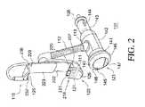
- FIG. 2illustrates an isometric view of the electrical accessory of FIG. 1 , according to the first embodiment
- FIG. 3illustrates a side view of the electrical accessory of FIG. 1 coupled to the electrical device of FIG. 1 , according to the first embodiment
- FIG. 4illustrates a block diagram of the electrical accessory of FIG. 1 , according to the first embodiment
- FIG. 5illustrates a side view of an electrical accessory, according to a second embodiment
- FIG. 6illustrates an example of a method of providing an electrical accessory, according to an embodiment
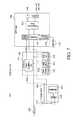
- FIG. 7illustrates another block diagram of the electrical accessory of FIG. 1 , according to the first embodiment.
- Coupleshould be broadly understood and refer to connecting two or more elements or signals, electrically, mechanically and/or otherwise.
- Two or more electrical elementsmay be electrically coupled but not be mechanically or otherwise coupled; two or more mechanical elements may be mechanically coupled, but not be electrically or otherwise coupled; two or more electrical elements may be mechanically coupled, but not be electrically or otherwise coupled.
- Couplingmay be for any length of time, e.g., permanent or semi-permanent or only for an instant.
- Electrode couplingand the like should be broadly understood and include coupling involving any electrical signal, whether a power signal, a data signal, and/or other types or combinations of electrical signals.
- Mechanical couplingand the like should be broadly understood and include mechanical coupling of all types.
- Some embodimentsdisclose an electrical accessory configured to transmit one or more first data signals from a first electrical device to a receiving device.
- the electrical accessoryis also configured to transmit second data signals to the first electrical device.
- the first electrical devicecan include a first electrical connector and a second electrical connector.
- the electrical accessorycan include: (a) a power acquisition unit configured to receive electrical power from an external power source; (b) a first electrical interface electrically coupled to the power acquisition unit and configured to mechanically and electrically couple to the first connector to provide the electrical power to the first electrical device; (c) a second electrical interface configured to mechanically and electrically couple to the second connector, the second electrical interface is configured to transmit the second data signals to the first electrical device and to receive the first data signals from the first electrical device; (d) a transmittal mechanism electrically coupled to the second electrical interface and configured to provide the first data signals to the receiving device; and (e) a first microphone electrically coupled to the second electrical interface and configured to receive sounds and convert the sounds into the second data signals.
- an electrical apparatusconfigured to couple to an electrical device.
- the electrical apparatuscan include: (a) a cradle for holding the electrical device; (b) a first coupling configured to transmit electrical power to the electrical device; (c) a second coupling configured to transmit first data to the electrical device and receive second data from the electrical device; (d) a first control configured to at least partially operate the electrical device; (e) a cigarette lighter adapter electrically coupled to the first coupling; (f) a gooseneck mechanically coupling the holder to the cigarette lighter adapter; (g) a microphone electrically coupled to the second coupling and configured to provide the first data to the first coupling; and (h) a transmitter electrically coupled to the second coupling.
- the transmittercan be configured to transmit the second data from the electrical device to an external speaker system.
- inventionscan disclose an electrical device configured to couple to a media device.
- the electrical devicecan include: (a) a first coupling configured to transmit first data to the media device and receive second data from the media device; (b) a first control configured to at least partially operate the media device; (c) a microphone electrically coupled to the first coupling and configured to provide the first data to the first coupling; (d) a transmitter electrically coupled to the first coupling, the transmitter is configured to transmit the second data received from the media device to an external speaker system; (e) a first housing at least partially enclosing the transmitter, the first housing comprising a first coupling mechanism; (f) a cigarette lighter adapter configured to couple to an external electrical power source and configured to provide electrical power to at least the microphone, the transmitter, and the first control; and (g) a second housing at least partially enclosing the cigarette lighter adapter, the second housing comprising a second coupling mechanism.
- the first coupling mechanismis configured to couple to the second coupling mechanism such that the first
- a method of providing an electrical accessorycan include: (a) providing a power acquisition unit configured to receive power from an external power source; (b) providing a first electrical interface such that the first electrical interface can be mechanically and electrically coupled to a first connector of a first electrical device; (c) electrically coupling the first electrical interface to the power acquisition unit; (d) providing a second electrical interface such that the second electrical interface can be mechanically and electrically coupled to a second connector of the first electrical device to transmit first data signals to the first electrical device and to receive second data signals from the first electrical device; (e) providing a transmittal mechanism such that the transmittal mechanism can provide the second data signals to a receiving device; (f) electrically coupling the transmittal mechanism to second electrical interface; (g) providing a first microphone such that the first microphone can receive sounds and convert the sounds into the first data signals; and (h) electrically coupling the first microphone to the second electrical interface.
- FIG. 1illustrates an overview of a system 100 for transmitting data signals between an electrical device 190 ; a receiving device 195 , and electrical accessory 101 , according to a first embodiment.
- electrical accessory 101can be configured to transmit one or more first data signals from electrical device 190 to receiving device 195 and also provide second data signals to electrical device 190 .
- System 100 and electrical accessory 101are merely exemplary and are not limited to the embodiments presented herein. System 100 and electrical accessory 101 can be employed in many different embodiments or examples not specifically depicted or described herein.
- electrical device 190is an electrical device configured to produce and receive electrical signals.
- electrical device 190can be a cellular (or mobile) phone, a laptop computer, an audio playback device, a portable AM (amplitude modulated) and FM (frequency modulated) radio, a satellite radio, a portable CD (compact disk) player, a data storage device, an audio player, an audio-visual player, and/or a portable media (e.g., MP3) player.
- the term “electrical device 190 ”includes electrical devices of all types and designs, including, but not limited to, any of the types of devices described above and/or any combination thereof.
- electrical device 190could be an iPhoneTM device, manufactured by Apple Computers, Inc. of Cupertino, Calif.
- the iPhoneTM deviceincludes an MP3 player, an audio visual player, and a cellular telephone.
- Receiving device 195can be any electrical device that includes a receiver configured to receive radio frequency (or other high frequency) signals.
- receiving device 195can be a radio.
- Receiving device 195can include or be coupled to one or more speakers 196 .
- the car radiocan be electrically coupled to the car's speaker system.
- the set of radio frequenciescan include the full FM band.
- the FM bandincludes the frequencies or channels between 87.5 MHz (megahertz) and 108 MHz.
- the FM bandincludes frequencies between 76 MHz and 90 MHz.
- the FM bandincludes frequencies between 87.6 MHz and 107.9 MHz.
- the full FM bandcan scan other ranges of radio frequencies.
- the set of radio frequenciesinclude other carrier frequency sets or bands (e.g., the AM (amplitude modulated) band, the VHF (very high frequency) band, or the UHF (ultra high frequency) band).
- FIG. 2illustrates an isometric view of electrical accessory 101 , according to the first embodiment.
- FIG. 3illustrates a side view of electrical accessory 101 coupled to electrical device 190 , according to the first embodiment.
- FIG. 4illustrates a block diagram of electrical accessory 101 , according to the first embodiment.
- FIG. 7illustrates another block diagram of electrical accessory 101 , according to the first embodiment
- electrical accessory 101can include: (a) a cradle or holder 111 configured to hold or couple to electrical device 190 ; (b) a connector 112 ; (c) a power acquisition unit 113 configured to receive electrical power from an external power source; (d) an electrical interface 214 ( FIGS. 2 and 4 ) electrically coupled to power acquisition unit 113 and configured to mechanically and electrically couple to electrical device 190 ; (e) an electrical interface 115 configured to mechanically and electrically couple to electrical device 190 ; (f) at least one transmittal mechanism or transmitter 416 ( FIG. 4 ) electrically coupled to electrical interface 115 and configured to provide data signals to receiving device 195 ; (g) at least one microphone 417 ( FIG. 3 ) electrically coupled to electrical interface 115 and configured to receive sounds and convert the sounds into data signals; and (h) a control or user communications module 420 ( FIG. 4 ).
- portions of electrical interface 214 , electrical interface 115 , transmitter 416 , microphone, user control module 420can include or be controlled by a microprocessor circuit 703 ( FIG. 7 ).
- microprocessor circuit 703can be a microprocessor no. C8051T611-GM, manufactured by Silicon Laboratories, Inc. of Austin, Tex. or microcontroller no. ST72F264G2H1, manufactured by Singapore Technologies of Singapore.
- electrical accessory 101can include three or more electrical circuitry boards 704 , 705 , and 706 ( FIG. 7 ).
- microphone 417 , button 129 , and electrical coupling 231can be located on or electrically coupled to electrical circuitry board(s) 704 .
- Power acquisition unit 113 , and connectors 351 , 352 , and 353can be located on or electrically coupled to electrical circuitry board(s) 705 .
- Transmitter 416 , antenna matching circuit 419 , microprocessor circuit 703 , display 145 , and buttons 146 , 147 , 148 , and 149can be located on or electrically coupled to electrical circuitry board(s) 706 .
- electrical interface 214can include an electrical coupling 231 and the electronic circuitry necessary to electrically couple to and communicate with electrical device 190 .
- electrical interface 115can include an electrical coupling 232 ( FIG. 2 ) and the electronic circuitry necessary to electrically couple to and communicate with electrical device 190 .
- electrical coupling 231can include a power coupling and a signal coupling.
- the power coupling and the signal couplingcan each be one or more pins in electrical coupling 231 . In various embodiments, only the power coupling in electrical coupling 231 is used by electrical accessory 101 .
- electrical accessory 101can be electrically coupled to electrical device 190 through electrical couplings 231 and 232 .
- Electrical device 190can also be mechanically coupled to electrical accessory 101 using holder 111 .
- Electrical accessory 101can receive data signals from electrical device 190 (e.g., an iPhoneTM device) through electrical coupling 232 and wirelessly transmit the data signals to receiving device 195 (e.g., a car radio) over a radio frequency using transmitter 416 and an antenna 418 ( FIG. 4 ).
- Microphone 417can receive sounds (e.g., a user's voice) and convert the sounds into data signals that are provided to electrical device 190 .
- electrical device 190includes a cellular telephone
- the data signals transmitted from electrical accessory 101 to receiving device 195are the incoming audio from the cellular telephone; and the data signals provided to electrical device 190 from electrical accessory 101 can be the outgoing audio.
- electrical accessory 101 and receiving device 195can function as a speaker system (i.e., a speaker phone) for electrical device 190 with the speakers, for example, being the car speaker system.
- electrical device 190can include a media player.
- Electrical accessory 101can receive data signals (e.g., the audio) from electrical device 190 through electrical interface 115 and wirelessly transmit the data signals to receiving device 195 (e.g., a car radio) over a radio frequency via transmitter 416 .
- data signalse.g., the audio
- receiving device 195e.g., a car radio
- Electrical accessory 101can also at least partially control electrical device 190 using electrical device controls 122 .
- electrical device controls 122can include a single button 129 that allows the user to answer or end a telephone call, or to play, pause, fast forward and/or rewind audio being played on electrical device 190 .
- Electrical accessory 101can also be coupled to an external power source (e.g., a cigarette lighter of a vehicle) and provide electrical power to electrical device 190 through electrical interface 214 .
- an external power sourcee.g., a cigarette lighter of a vehicle
- Cradle or holder 111can include: (a) a base portion or base 121 configured to couple to at least one electrical device 190 ; (b) one or more extension portions or extensions 222 and 223 ( FIG. 2 ) extending away from base 121 , and (c) at least one clasp or support 125 .
- Base 121can be configured to couple to a side (e.g., the bottom) of electrical device 190 .
- base 121includes a substantially level top surface 226 with electrical coupling 231 protruding from an aperture in top surface 226 .
- electrical device 190can be placed on top surface 226 and coupled to electrical coupling 231 .
- electrical coupling 231can protrude from other portions of holder 111 such as, for example, extension 222 , extension 223 , or support 125 .
- base 121can include an interior cavity (not shown). This interior cavity can house a portion of the electronic circuitry necessary to operate electrical accessory 101 .
- This interior cavitycan house a portion of the electronic circuitry necessary to operate electrical accessory 101 .
- a portion of electrical coupling 231 , a portion of electrical device controls 122 , microphone 417 , and at least a portion of the electronic circuitry need to operate electrical coupling 231 , electrical device controls 122 , and microphone 417can be located in the interior cavity of base 121 .
- electrical device 190e.g., the iPhoneTM device
- transmitter device(s)e.g., radio frequency or cellular transmitters
- a portion of the electronic circuitry of electrical accessory 101can be placed immediately underneath electrical coupling 231 , instead of at other portions of base 121 or holder 111 . Placing the electronic circuitry below electrical coupling 231 can help minimize the interference between this electronic circuitry and the transmitter device(s) of electrical device 190 .
- electrical circuitry boards 704 and/or 706can be placed below electrical coupling 231 .
- Base 121can be coupled to end 237 ( FIG. 2 ) of extension 222 .
- Support 125can be coupled to end 238 ( FIG. 2 ) of extension 223 .
- Extension 222can be adjustably coupled to extension 223 such that a distance 330 ( FIG. 3 ) between base 121 and support 125 can be adjusted to correspond to the length or height of electrical device 190 .
- a portion of extension 222can abut extension 223 and be coupled together using an adjustable mechanism.
- Extensions 222 and extension 223can be coupled such that the portion of extension 222 abutting extension 223 can be increased or decreased to change distance 330 .
- the abutting portion of extension 223can be coupled with a screw or bolt to extension 222 .
- other adjustable coupling mechanismse.g. magnets, friction, hook and loop material such as Velcro® material, etc.
- distance 330can be adjusted to any distance in a predetermined range. For example, distance 330 can be adjusted in the range of approximately 65 millimeters to approximately 120 millimeters.
- Support 125can be coupled to extension 223 such that the combination of support 125 , extensions 222 and 223 , base 121 , and electrical coupling 231 securely holds electrical device 190 to electrical accessory 101 .
- support 125 and extensions 222 and 223can be designed and manufactured such that after electrical device 190 is coupled to electrical coupling 231 , distance 330 can be slightly increased to allow electrical device 190 to be slid into groove 229 ( FIG. 2 ) of support 125 . That is, support and/or extensions 222 and 223 are constructed from a material that is bendable or pliable enough to allow insertion of electrical device 190 into groove 229 but rigid enough to hold securely electrical device 190 in groove 229 after insertion.
- holder 111is rotatably coupled to connector 112 . That is, holder 111 (and electrical device 190 ) can be rotated relative to connector 112 and power acquisition unit 113 . In some examples, a point on holder 111 can be rotated clockwise or counterclockwise one hundred and eighty degrees relative to a point on connector 112 and a point on power acquisition unit 113 .
- Connector 112can be a semi-rigid elongated portion configured to allow a position of holder 111 to be semi-permanently adjusted relative to a position of the power acquisition unit 113 .
- connector 112can include a gooseneck, which can be compliant (or obedient) flexible tubing, and is preferably metallic or metal covered with, e.g., plastic or elastic material on its outside.
- a gooseneckcan be considered to be a coiled layered construction in which adjacent coils overlap but can be moved with respect to each other (in a sense, slide on each other).
- Gooseneckstends to hold the position into which it is bent (i.e., it is semi permanently adjustable or repositionable), unless it is bent beyond its limit.
- a gooseneckhas two outer diameters, the outer diameter of the thicker layer, and the outer diameter of the thinner layer, which alternate in the gooseneck.
- connector 112can be between 7.5 centimeters (cm) and 15.2 cm (e.g., approximately 11.4 long cm); its larger outer diameter is approximately 9 millimeters (mm); its smaller outer diameter is approximately 8.2 millimeters; its inner diameter is approximately 4.5 millimeters; the center-to-center spacing between the larger diameter portions is approximately 3.5 millimeters; the longitudinal gap between the larger diameter portions is approximately 1 millimeter; and the material of construction can be steel.
- Connector 112must not be so stiff that it cannot be readily repositioned by the user; however, it must be stiff enough to maintain holder 111 (with electrical device 190 ) in position with respect to power acquisition unit 113 after holder 111 and connector 112 have been put into their desired position.
- Connector 112 used in some embodimentsare available in varying dimensions (e.g., outer diameters of 2 millimeter or less to over 16 millimeters). Connector 112 can be implemented with a design, dimensions, and materials of construction to select for any particular usage based on the desired length of connector 112 , the weight of holder 111 and electrical device 190 to be held in it, whether connector 112 is to function as a broadcast antenna and, if so, for what range of radio frequencies.
- Power acquisition unit 113includes: (a) an end portion 141 ; (b) a middle portion 142 ; and (c) an end portion 143 .
- Connector 112can be coupled to middle portion 142 .
- connector 112can be coupled to end portion 141 or 143 .
- end portion 141has a larger diameter than middle portion 142
- middle portion 142has a larger diameter than end portion 143 .
- an internal cavityexists inside of end portion 141 , end portion 143 , and middle portion 142 .
- This internal cavitycan contain the electrical circuitry for obtaining power from an external power source (e.g., electrical circuitry board(s) 705 ) such as a cigarette lighter and then processing the electrical power (i.e., the circuitry for cigarette lighter adapter).
- the internal cavitycan also contain electrical circuitry for transmitter 416 and transmitter controls 123 (e.g. electrical circuitry board(s) 706 ).
- the electrical circuitry for transmitter 416 and transmitter controls 123can be located in end portion 141 .
- the power acquisition unit 113is preferably removably coupleable to an external power source (e.g., cigarette lighter), the power acquisition unit 113 can in some cases be permanently affixed to the external power source.
- an external power sourcee.g., cigarette lighter
- the power acquisition unit 113can in some cases be permanently affixed to the external power source.
- a driver of a vehicle who does not smokemay obtain electrical accessory 101 and hard-wire it into the cigarette lighter of the vehicle.
- power acquisition unit 113is configured to couple to a cigarette lighter of a vehicle. That is, power acquisition unit 113 includes a cigarette lighter adapter.
- cigarette lighteris to be broadly understood and includes any power source, whether or not in a vehicle and whether or not customarily used or designed for lighting cigarettes.
- cigarette lighter adapteris to be broadly understood and includes any member, device, etc. at least a part of which mechanically mates with or fits into a “cigarette lighter” (as that term is to be broadly understood) and can draw power from it.
- End portion 143can be configured to be inserted into an external power source such as the cigarette lighter of a vehicle, which is usually a cylindrical cavity.
- an external power sourcesuch as the cigarette lighter of a vehicle, which is usually a cylindrical cavity.
- non-conductive stabilizing springs 144are provided on opposite sides of end portion 143 .
- Stabilizer 135can include a deformable resilient member that is larger than the inner circumference of essentially all known vehicle cigarette lighters so that pushing end portion 143 into the cigarette lighter causes the outer circumference of the deformable resilient member to bend away from the distal end of end portion 143 (i.e., the part of end portion farthest from middle portion 142 ) and towards the proximal end of end portion 143 (the part of end portion 143 closest to middle portion 142 ) while at least some of the deformable resilient member even after such deformation continues to push against the inner circumference of the cigarette lighter.
- Stabilizer 135allows power acquisition unit 113 to fit in the cigarette lighter of virtually any vehicle to mechanically and electrically semi-permanently (firmly but removably) couple electrical accessory 101 to keep power acquisition unit 113 in the desired position and maintain good electrical contact with the cigarette lighter. Stabilizer 135 retards or prevents undesired rotation, wobbling, and longitudinal movement of power acquisition unit 113 in the cigarette lighter. Thus, stabilizer 135 tends to prevent normal vibration, centrifugal forces (from the vehicle's turning), and bumps in the road from moving power acquisition unit 113 (and therefore the electrical accessory 101 ) from its desired position.
- Transmitter 416can be configured to transmit data over the at least one radio frequency using antenna 418 .
- Transmitter 416can be electrically coupled to electrical interface 115 and configured to transmit data signals (e.g., audio signals) to external speakers 196 coupled to receiving device 195 .
- transmitter 416includes a radio frequency transmitter.
- Transmitter 416can be coupled to antenna 418 through antenna matching circuit 419 ( FIG. 4 ).
- connector 112e.g., the gooseneck portion of connector 112
- the output of transmitter 416(an electrical signal) is coupled to an attenuation circuit (not shown).
- the amount of attenuation that is needed to comply with FCC requirementsis dictated by the output of the particular transmitter, the quality, and type of antenna that is being utilized, and the environment in which the transmitter is being used. Consequently, the specific design of the attenuation circuit is a matter of design choice depending upon the needs of the particular application. For some types of electrical signals to be broadcast by transmitter 416 , an attenuation circuit will not be needed. In some embodiments, the attenuation circuit can be a portion of antenna matching circuit 419 .
- electrical accessory 101can be coupled to an external antenna (not shown) through an external antenna matching circuit (not shown) in addition to or instead of antenna 418 . Electrical accessory 101 can send and/or receive electrical signals using the external antenna.
- User communications module 420can include: (a) transmitter controls 123 ; and (b) electrical device controls 122 .
- Transmitter controls 123can include: (a) buttons 146 , 147 , 148 , and 149 ; (b) display 145 ; and (c) the electrical circuitry to implement buttons 146 , 147 , 148 , and 149 and display 145 .
- button 148can be semi-permanently set to select a radio frequency (i.e., a transmission frequency) for transmitter 416 to transmit the data signal to receiving device 195 .
- button 149can be semi-permanently set to select an audio mode (e.g., AM or FM) for the data signals.
- Button 147can be semi-permanently set to select a radio frequency for transmitter 416 from a memory (not shown) within electrical accessory 101 .
- Button 149can be used to scan for an open radio frequency for transmitter 416 .
- buttons 146 , 147 , 148 , and 149can be covered with a protective membrane.
- buttons 146 , 147 , 148 , and 149are devoid of a protective membrane and/or protrude from holder 111 .
- Display 145can be used to display information about the selected transmission frequency or audio mode.
- display 145can display the carrier frequency in the format “XXX.X.”
- video screencan either display a predetermined name for an audio mode (e.g., “SPOKEN WORD MODE”) or a list of settings (e.g., “Dynamic Compressor On” and/or “Output Mode: Stereo”).
- display 145can show the transmission frequency and audio mode information simultaneously.
- the information shown on display 145is related to the last pressed button of buttons 146 , 147 , 148 , and 149 or predetermined default information.
- display 145is an LCD (liquid crystal display).
- display 145can be a touch screen.
- end portion 141 , display 145 , and buttons 146 , 147 , 148 , and 149can be rotated relative to middle portion 142 and end portion 143 .
- a point on end portion 141 , display 145 , and buttons 146 , 147 , 148 , and 149can be rotated clockwise or counterclockwise two hundred and seventy degrees relative to a point on middle portion 142 and a point on end portion 143 .
- Electrical device controls 122can include button 129 and the electrical circuitry to implement the electrical device controls. Electrical device controls 122 are configured to at least partially control electrical device 190 .
- button 129can be used to begin and end a telephone call when electrical device 190 includes a cellular telephone. Button 129 can also be used to play, pause, fast forward, and rewind when electrical device 190 is configured to play music or other audio.
- the providing of audio by electrical device 190can be started with a push of button 129 .
- a second push of button 129can pause the audio.
- a third push of button 129 immediately after the second pushi.e., two pushes of button 129 in immediate succession
- a fourth push of button 129 immediately after the third pushi.e., three pushes of button 129 in immediate succession
- Other functionalitycan be implemented with other combinations of pushing of button 129 (e.g., four pushes of button 129 in immediate succession).
- a push of button 129when receiving an incoming telephone call, can interrupt other functions (e.g., stop any playing audio) and answer the telephone call. Similarly, another push of button 129 can end the telephone call and restart any other functions stopped when the telephone call was answered (e.g., resume playing the audio stopped when the telephone call was received).
- electrical device controls 122can be implemented with two or more buttons.
- electrical device controls 122can include a play/pause button, a stop button, a forward button, a back button, an answer/hang-up button, etc.
- buttonsare shown in FIGS. 1-3 , any type of button can be used, and the term “button” should be broadly understood to refer to any type of mechanism (with or without moving parts) whereby the user can input to electrical accessory 101 his or her data (for example, selection of a frequency), e.g., a mechanical pushbutton, an electrostatic pushbutton, an electrostatic array, or any other input device of any type.
- the iPhoneTM deviceincludes a thirty-pin female connector (i.e., a dock connector) configured to receive electrical power and transfer data signals.
- the iPhoneTM devicealso includes a 3.5 millimeter (mm) female TRS (Tip, Ring, Sleeve,) connector (e.g., a headphone jack) for transferring data signals.
- electrical interfaces 214 and 115can be configured to couple to these two connectors on the iPhoneTM device.
- electrical coupling 231can be a thirty-pin male connector configured to mechanically and electrically couple to a thirty-pin female connector (not shown) on electrical device 190 .
- electrical interface 214can also be configured to send and receive data signals from electrical device 190 .
- the ability of electrical coupling 231 to transfer data signals with electrical device 190is not utilized in many embodiments of electrical accessory 101 because the data signal transfer with electrical device 190 is handled by electrical coupling 232 .
- Electrical coupling 232can be configured to mechanically and electrically couple to a corresponding connector (not shown) on electrical device 190 .
- electrical coupling 232can be a 3.5 mm male TSR connector.
- electrical interface 115can includes other connectors that correspond to electrical connectors on electrical device 190 .
- Electrical accessory 101can use electrical interface 115 to receive data (e.g., audio) signals from electrical device 190 and to provide data signals from microphone 417 or audio input connector 353 to electrical device 190 .
- Microphone 417can be electrically coupled to electrical interface 115 and configured to provide data signals to electrical interface 115 .
- Microphone 417can be located at holder 111 .
- microphone 417is located at base 121 (e.g., at the right and/or left side of base 121 where no buttons are located).
- microphone 417can be located at extensions 222 , extension 223 , support 125 , or electrical power acquisition unit 113 .
- microphone 417is located at base 121 instead of at extension 222 , extension 223 , support 125 , or electrical power acquisition unit 113 because locating microphone at base 121 can provide better pick-up of voices and other audio.
- electrical accessory 101can include one or more additional electrical interfaces.
- electrical accessory 101can further include: (a) an audio output connector 351 ; (b) power output connector 352 ; and (c) a microphone input port or audio input connector 353 .
- audio output connector 351 , audio output connector 351 , power output connector 352 , and audio input connector 353can be located at middle portion 142 .
- audio output connector 351can be a 3.5 mm female TSR connector. In some examples, audio output received from electrical device 190 through electrical interface 115 can be provided to audio output connector 351 . Audio output connector 351 can be electrically and mechanically coupled to receiving device 195 to provide the data signals from electrical device 190 to receiving device 195 . In some examples, electrical accessory 101 does not include transmitter 416 , and audio output connector 351 can be the sole means for communicating data signals to receiving device 195 . In some examples, audio output connector 351 can be considered part of transmitter 416 .
- Power output connector 352can be electrically coupled to power acquisition unit 113 and configured to provide electrical power to other electrical devices.
- power output connector 352can be a female universal serial bus connector.
- Audio input connector 353can be electrically coupled to electrical interface 115 .
- an external microphone or other external audio input devicecan be coupled to audio input connector 353 to provide data signals to electrical device 190 .
- the external audio input devicecan be used to provide data signals to electrical device 190 instead of or in addition to microphone 417 .
- audio input connector 353is a 3.5 mm female TSR connector.
- FIG. 5illustrates a side view of electrical accessory 501 , according to a second embodiment.
- Electrical accessory 501can be similar to electrical accessory 101 ( FIG. 1 ), except that electrical accessory 501 does not have holder 111 . More specifically, electrical accessory 501 can include: (a) electrical interface 115 configured to mechanically and electrically couple to electrical device 190 ( FIG. 1 ); (b) at least one transmitter mechanism or transmitter 416 ( FIG. 4 ) electrically coupled to electrical interface 115 and configured to provide data signals to receiving device 195 ( FIG.
- User communications module 520can include: (a) a transmitter controls 123 ; and (b) electrical device controls 122 .
- power acquisition unit 513can include: (a) a housing 543 that at least partially encloses a cigarette lighter adapter; (b) springs 144 ; and (c) stabilizer 135 .
- electrical accessory 501can be electrically coupled to electrical device 190 through electrical interfaces 115 .
- Electrical accessory 501can receive data signals from electrical device 190 (e.g., an iPhoneTM device) through electrical interface 115 and wirelessly transmit the data signals to receiving device 195 (e.g., a car stereo) over a radio frequency via transmitter 416 .
- Microphone 417can receive sounds and convert the sounds into data signals that are provided to electrical device 190 .
- electrical device 190includes a cellular telephone; the data signals transmitted from electrical accessory 501 to receiving device 195 are the incoming audio from the cellular telephone; and the data signals provided to electrical device 190 by electrical accessory 501 can be the outgoing audio.
- electrical accessory 501 and receiving device 195can function as a speaker system (i.e., a speaker phone) for electrical device 190 with the speakers, for example, being the car speaker system.
- electrical device 190can include a media player.
- Electrical accessory 501can receive data signals from electrical device 190 through electrical interface 115 and wirelessly transmit the data signals to receiving device 195 (e.g., a car radio and speaker system) over a radio frequency.
- receiving device 195e.g., a car radio and speaker system
- Electrical accessory 501can also at least partially control electrical device 190 using electrical device controls 122 .
- Electrical device controls 122can include a single button that allows the user to answer or end a telephone call, and/or to play, pause, fast forward and/or rewind audio played by electrical device 190 .
- coupling mechanism 560can be coupled to coupling mechanism 561 such that housing 565 is supported by power acquisition unit 513 . That is, coupling mechanism 560 is configured to mechanically couple to coupling mechanism 561 to hold housing 565 adjacent to power acquisition unit 513 .
- housing 565can be coupled to power acquisition unit 513 such that electrical device controls 122 are easily accessible to the operator of the vehicle and do not interfere with the vehicle controls (including the radio of the vehicle).
- coupling mechanism 560includes a first magnet.
- Coupling mechanism 561can include a second magnet. The first magnet can be coupled to the second magnet to hold housing 565 adjacent to power acquisition unit 513 .
- coupling mechanism 560 and coupling mechanism 561can be other complementary coupling mechanisms.
- coupling mechanisms 560 and 561could be snaps, Velcro® material, etc.
- coupling mechanism 561is not located at power acquisition unit 513 , but is designed to be affixed to a portion of the car, such as the dash board.
- FIG. 6illustrates an example of a method 600 of providing an electrical accessory, according to an embodiment.
- Method 600is merely exemplary, and is not limited to the specific embodiments or examples presented herein. Accordingly, method 600 can be employed in many other sequences, embodiments, or examples not specifically depicted or described herein.
- Method 600includes an activity 610 of providing a power acquisition unit.
- the power acquisition unitcan be configured to receive power from an external power source.
- the power acquisition unitcan be similar or identical to power acquisition unit 113 or 513 of FIGS. 1 and 5 , respectively.
- the external power sourcecan be a vehicle cigarette lighter
- the power acquisition unitcan include a vehicle cigarette lighter adapter.
- Method 600 in FIG. 6continues with an activity 615 of providing a first electrical interface.
- the first electrical interfacecan mechanically and electrically couple to a first connector of the first electrical device.
- the first electrical interfacecan be similar or identical to electrical interface 214 of FIGS. 2 and 4 .
- method 600 of FIG. 6includes an activity 620 of electrically coupling the first electrical interface to the power acquisition unit.
- the coupling of the first electrical interface to the power acquisition unitcan be similar or identical to the coupling of power acquisition unit 113 to electrical interface 214 .
- method 600does not include activities 615 and 620 .
- Method 600 of FIG. 6further includes an activity 625 of providing a second electrical interface.
- the second electrical interfacecan be configured to mechanically and electrically couple to a second connector of the first electrical device to transmit first data signals to the first electrical device and receive second data signals from the first electrical device.
- the second electrical interfacecan be similar or identical to electrical interface 115 of FIGS. 1-5 .
- the second connector of the first electrical devicecan be a 3.5 mm female TSR connector, and the second electrical interface can include a 3.5 mm male TSR connector.
- Method 600 in FIG. 6continues with an activity 630 of providing a transmittal mechanism.
- the transmittal mechanismcan provide the second data signals to the receiving device.
- the receiving devicecan be similar or identical to receiving device 195 of FIG. 1 .
- the transmittal mechanismcan be similar or identical to transmitter 416 of FIG. 4 .
- the transmitter mechanismcan be similar to or identical to an audio output connector 351 of FIGS. 3 and 5 .
- the transmittal mechanismcan include transmitter 416 and audio output connector 351 .
- method 600 of FIG. 6includes an activity 635 of electrically coupling the transmittal mechanism to the second electrical interface.
- the electrical coupling of transmittal mechanism to the second electrical interfacecan be similar or identical to the electrical coupling of transmitter 416 to electrical interface 115 and/or the electrical coupling of audio output connector 351 to electrical interface 115 .
- Method 600 of FIG. 6further includes an activity 640 of providing at least one microphone.
- the at least one microphonecan receive sounds and convert the sounds into the first data signals.
- the at least one microphonecan be similar or identical to microphone 417 of FIG. 4 .
- Method 600 in FIG. 6continues with an activity 645 of electrically coupling the at least one microphone to the second electrical interface.
- the electrical coupling of the at least one microphone to the second electrical interfacecan be similar or identical to the electrical coupling of microphone 417 to electrical interface 115 .
- the order of activities 610 through 645can be modified.
- activities 640 and 645can occur simultaneously with activities 610 - 620 and/or 625 - 635 .
- electrical accessory 501could include electrical interface 214 ( FIG. 2 ).
- method 600could include activities for providing a first coupling mechanism and a second coupling mechanism where the first coupling mechanism and the second coupling mechanism are similar or identical to coupling mechanisms 560 and 561 of FIG. 5 . Additional examples of such changes have been given in the foregoing description. Accordingly, the disclosure of embodiments is intended to be illustrative of the scope of the invention and is not intended to be limiting.
- embodiments and limitations disclosed hereinare not dedicated to the public under the doctrine of dedication if the embodiments and/or limitations: (1) are not expressly claimed in the claims; and (2) are or are potentially equivalents of express elements and/or limitations in the claims under the doctrine of equivalents.
Landscapes
- Engineering & Computer Science (AREA)
- Signal Processing (AREA)
- Computer Networks & Wireless Communication (AREA)
- Mechanical Engineering (AREA)
- Multimedia (AREA)
- Theoretical Computer Science (AREA)
- General Physics & Mathematics (AREA)
- General Engineering & Computer Science (AREA)
- Physics & Mathematics (AREA)
- Power Engineering (AREA)
- Telephone Set Structure (AREA)
- Camera Bodies And Camera Details Or Accessories (AREA)
- Transmitters (AREA)
- Telephone Function (AREA)
- Measuring Pulse, Heart Rate, Blood Pressure Or Blood Flow (AREA)
- Arrangements For Transmission Of Measured Signals (AREA)
Abstract
Description
Claims (30)
Priority Applications (17)
| Application Number | Priority Date | Filing Date | Title |
|---|---|---|---|
| US12/349,505US8295770B2 (en) | 2005-10-11 | 2009-01-06 | Electrical accessory and method of providing same |
| US12/545,017US8254846B2 (en) | 2004-09-08 | 2009-08-20 | Connectivity device and method of providing same |
| PCT/US2010/020265WO2010080839A1 (en) | 2009-01-06 | 2010-01-06 | Electrical accessory and method of providing same |
| JP2011544679AJP2012514907A (en) | 2009-01-06 | 2010-01-06 | Electrical accessory and method of providing the same |
| CA2749140ACA2749140A1 (en) | 2009-01-06 | 2010-01-06 | Electrical accessory and method of providing same |
| AU2010203718AAU2010203718A1 (en) | 2009-01-06 | 2010-01-06 | Electrical accessory and method of providing same |
| MX2011007219AMX2011007219A (en) | 2009-01-06 | 2010-01-06 | Electrical accessory and method of providing same. |
| KR1020117015919AKR20110111400A (en) | 2009-01-06 | 2010-01-06 | Electrical accessories and how to provide them |
| BRPI1006070ABRPI1006070A2 (en) | 2009-01-06 | 2010-01-06 | electrical accessory and delivery method |
| EP10729470AEP2374218A4 (en) | 2009-01-06 | 2010-01-06 | Electrical accessory and method of providing same |
| CN2010800105696ACN102342030A (en) | 2009-01-06 | 2010-01-06 | Electrical accessory and method for providing the same |
| NZ593978ANZ593978A (en) | 2009-01-06 | 2010-01-06 | Electrical accessory including microphone and lighter |
| US12/749,463US20100273421A1 (en) | 2004-09-08 | 2010-03-29 | Electrical accessory configured to transmit electrical signals between a first electrical device, a second electrical device and a third electrical device and a method of providing and using the electrical accessory |
| US13/089,141US20110255226A1 (en) | 2004-09-08 | 2011-04-18 | Electrical Accessory and Method of Providing Same |
| US13/595,917US20120322514A1 (en) | 2004-09-08 | 2012-08-27 | Connectivity Device and Method of Providing Same |
| US13/730,430US20130112838A1 (en) | 2004-09-08 | 2012-12-28 | Electrical Accessory and Method of Providing Same |
| US14/094,538US20140084126A1 (en) | 2004-09-08 | 2013-12-02 | Electrical Accessory and Method of Providing Same |
Applications Claiming Priority (3)
| Application Number | Priority Date | Filing Date | Title |
|---|---|---|---|
| US11/248,762US7734256B2 (en) | 2005-10-11 | 2005-10-11 | System for interfacing with an audio player, and method of manufacturing same |
| US11/842,921US7930004B2 (en) | 2004-09-08 | 2007-08-21 | Holder, electrical supply, and RF transmitter unit for electronic devices |
| US12/349,505US8295770B2 (en) | 2005-10-11 | 2009-01-06 | Electrical accessory and method of providing same |
Related Parent Applications (3)
| Application Number | Title | Priority Date | Filing Date |
|---|---|---|---|
| US10/936,356Continuation-In-PartUS7292881B2 (en) | 2004-09-08 | 2004-09-08 | Holder, electrical supply, and RF transmitter unit for electronic devices |
| US11/248,762Continuation-In-PartUS7734256B2 (en) | 2004-09-08 | 2005-10-11 | System for interfacing with an audio player, and method of manufacturing same |
| US11/842,921Continuation-In-PartUS7930004B2 (en) | 2004-09-08 | 2007-08-21 | Holder, electrical supply, and RF transmitter unit for electronic devices |
Related Child Applications (3)
| Application Number | Title | Priority Date | Filing Date |
|---|---|---|---|
| US12/545,017Continuation-In-PartUS8254846B2 (en) | 2004-09-08 | 2009-08-20 | Connectivity device and method of providing same |
| US12/545,017ContinuationUS8254846B2 (en) | 2004-09-08 | 2009-08-20 | Connectivity device and method of providing same |
| US12/749,463Continuation-In-PartUS20100273421A1 (en) | 2004-09-08 | 2010-03-29 | Electrical accessory configured to transmit electrical signals between a first electrical device, a second electrical device and a third electrical device and a method of providing and using the electrical accessory |
Publications (2)
| Publication Number | Publication Date |
|---|---|
| US20090186583A1 US20090186583A1 (en) | 2009-07-23 |
| US8295770B2true US8295770B2 (en) | 2012-10-23 |
Family
ID=42316792
Family Applications (1)
| Application Number | Title | Priority Date | Filing Date |
|---|---|---|---|
| US12/349,505Expired - Fee RelatedUS8295770B2 (en) | 2004-09-08 | 2009-01-06 | Electrical accessory and method of providing same |
Country Status (11)
| Country | Link |
|---|---|
| US (1) | US8295770B2 (en) |
| EP (1) | EP2374218A4 (en) |
| JP (1) | JP2012514907A (en) |
| KR (1) | KR20110111400A (en) |
| CN (1) | CN102342030A (en) |
| AU (1) | AU2010203718A1 (en) |
| BR (1) | BRPI1006070A2 (en) |
| CA (1) | CA2749140A1 (en) |
| MX (1) | MX2011007219A (en) |
| NZ (1) | NZ593978A (en) |
| WO (1) | WO2010080839A1 (en) |
Cited By (21)
| Publication number | Priority date | Publication date | Assignee | Title |
|---|---|---|---|---|
| US20130112838A1 (en)* | 2004-09-08 | 2013-05-09 | Belkin International, Inc. | Electrical Accessory and Method of Providing Same |
| US20140024247A1 (en)* | 2012-07-18 | 2014-01-23 | Quirky, Inc. | Wrappable extension cord apparatus and related methods |
| US8870146B2 (en)* | 2011-05-31 | 2014-10-28 | Nite Ize, Inc. | Multi-positional mount for personal electronic devices with a magnetic interface |
| USD734746S1 (en) | 2011-05-31 | 2015-07-21 | Nite Ize, Inc. | Phone kit |
| US20150296619A1 (en)* | 2013-08-06 | 2015-10-15 | Bedrock Automation Platforms Inc. | Industrial control system cable |
| USD824334S1 (en) | 2015-11-10 | 2018-07-31 | Kenneth Carson | Vehicular cell phone charger |
| US10613567B2 (en) | 2013-08-06 | 2020-04-07 | Bedrock Automation Platforms Inc. | Secure power supply for an industrial control system |
| US10628361B2 (en) | 2011-12-30 | 2020-04-21 | Bedrock Automation Platforms Inc. | Switch fabric having a serial communications interface and a parallel communications interface |
| US10824711B2 (en) | 2013-08-06 | 2020-11-03 | Bedrock Automation Platforms Inc. | Secure industrial control system |
| US10834094B2 (en) | 2013-08-06 | 2020-11-10 | Bedrock Automation Platforms Inc. | Operator action authentication in an industrial control system |
| US10832861B2 (en) | 2011-12-30 | 2020-11-10 | Bedrock Automation Platforms Inc. | Electromagnetic connector for an industrial control system |
| US10833872B2 (en) | 2013-08-06 | 2020-11-10 | Bedrock Automation Platforms Inc. | Industrial control system redundant communication/control modules authentication |
| US10848012B2 (en) | 2011-12-30 | 2020-11-24 | Bedrock Automation Platforms Inc. | Electromagnetic connectors for an industrial control system |
| US10896145B2 (en) | 2011-12-30 | 2021-01-19 | Bedrock Automation Platforms Inc. | Communications control system with a serial communications interface and a parallel communications interface |
| US11055246B2 (en) | 2011-12-30 | 2021-07-06 | Bedrock Automation Platforms Inc. | Input-output module with multi-channel switching capability |
| US11144630B2 (en) | 2011-12-30 | 2021-10-12 | Bedrock Automation Platforms Inc. | Image capture devices for a secure industrial control system |
| US11314854B2 (en) | 2011-12-30 | 2022-04-26 | Bedrock Automation Platforms Inc. | Image capture devices for a secure industrial control system |
| US11966349B2 (en) | 2011-12-30 | 2024-04-23 | Analog Devices, Inc. | Electromagnetic connector for for an industrial control system |
| US11967839B2 (en) | 2011-12-30 | 2024-04-23 | Analog Devices, Inc. | Electromagnetic connector for an industrial control system |
| US12061685B2 (en) | 2011-12-30 | 2024-08-13 | Analog Devices, Inc. | Image capture devices for a secure industrial control system |
| US12120819B2 (en) | 2014-07-07 | 2024-10-15 | Analog Devices, Inc. | Industrial control system cable |
Families Citing this family (10)
| Publication number | Priority date | Publication date | Assignee | Title |
|---|---|---|---|---|
| US7930006B2 (en)* | 2004-09-08 | 2011-04-19 | Belkin International, Inc. | Holder, electrical supply, and RF transmitter unit for electronic devices |
| US7292881B2 (en)* | 2004-09-08 | 2007-11-06 | Belkin International, Inc. | Holder, electrical supply, and RF transmitter unit for electronic devices |
| USD641342S1 (en)* | 2010-07-07 | 2011-07-12 | Nutek Corp. | Bluetooth controller for insertion with car cigarette lighters |
| US8630659B2 (en) | 2010-08-10 | 2014-01-14 | Toyota Motor Engineering & Manufacturing North America, Inc. | Systems and methods of delivering content to an occupant in a vehicle |
| US9760116B2 (en)* | 2012-12-05 | 2017-09-12 | Mobile Tech, Inc. | Docking station for tablet device |
| US10135304B2 (en) | 2013-09-05 | 2018-11-20 | Lg Innotek Co., Ltd. | Supporter |
| USD716788S1 (en)* | 2014-05-02 | 2014-11-04 | Toros Volkan | Hands-free speaker phone holder for cell-phone |
| US10101770B2 (en) | 2016-07-29 | 2018-10-16 | Mobile Tech, Inc. | Docking system for portable computing device in an enclosure |
| JP7112485B2 (en)* | 2017-05-21 | 2022-08-03 | レブ,ヤーロン | smart holder |
| CN118578993A (en)* | 2023-03-01 | 2024-09-03 | 华为技术有限公司 | On-board charging connection device and power supply system |
Citations (60)
| Publication number | Priority date | Publication date | Assignee | Title |
|---|---|---|---|---|
| USD244360S (en) | 1975-09-08 | 1977-05-17 | Van Kersen Philip L | Thermochromic thermometer |
| USD317579S (en) | 1989-05-25 | 1991-06-18 | Solar Wide Industrial Limited | Combined fluid alert and thermometer |
| US5230563A (en) | 1989-05-08 | 1993-07-27 | Solar Wide Industrial Ltd. | Liquid level monitoring device |
| USD357201S (en) | 1994-05-03 | 1995-04-11 | Novack James A | Electronic toilet seat signal reminder |
| US5642402A (en) | 1994-01-13 | 1997-06-24 | Nokia Mobile Phones Limited | Hands free equipment |
| USD381662S (en) | 1996-03-14 | 1997-07-29 | Micro Multimedia Labs Inc. | Remote control device |
| US5769369A (en) | 1995-04-28 | 1998-06-23 | Meinel; James | Mobile office stand for supporting a portable computer or electronic organizer in vehicles |
| US5860824A (en) | 1997-04-14 | 1999-01-19 | Fan; Eagle | Extension device for mounting in automobile cigarette lighter holder |
| US5967851A (en) | 1998-08-21 | 1999-10-19 | Rosslare Enterprises, Ltd. | Cigarette lighter adapter having plunger retention mechanism |
| US6052603A (en) | 1995-04-11 | 2000-04-18 | Mold-Tech Plastics Limited Partnership | System for interfacing a communication device with a radio for hands-free operation |
| USD435580S (en) | 1999-06-15 | 2000-12-26 | Bose Corporation | Controller |
| US20010041590A1 (en) | 1999-06-09 | 2001-11-15 | Shimon Silberfenig | Combination cellular telephone, sound storage device, and email communication device |
| US20020029091A1 (en) | 2000-09-06 | 2002-03-07 | Mitsumi Electric Co. Ltd. | Digital audio player capable of playing digital audio data through existing cassette tape player |
| US6377825B1 (en)* | 2000-02-18 | 2002-04-23 | Cellport Systems, Inc. | Hands-free wireless communication in a vehicle |
| USD462022S1 (en) | 2001-08-22 | 2002-08-27 | Actuant Corporation | Transmitter of an electrical circuit tracing device |
| USD463990S1 (en) | 2001-10-29 | 2002-10-08 | Joseph Clarenco Wysocki | Gauge for monitoring liquid level |
| US20020198031A1 (en)* | 2001-06-25 | 2002-12-26 | James Holmes David William | Method and apparatus for providing power and wireless protocol capability to a wireless device, such as a wireless phone |
| USD473207S1 (en) | 2001-11-09 | 2003-04-15 | Olympus Optical Co., Ltd. | Voice recorder and player having digital camera |
| US6591085B1 (en) | 2002-07-17 | 2003-07-08 | Netalog, Inc. | FM transmitter and power supply/charging assembly for MP3 player |
| USD479712S1 (en) | 2002-10-31 | 2003-09-16 | Koninklijke Philips Electronics N.V. | MP-3 digital audio player |
| USD483281S1 (en) | 2002-10-15 | 2003-12-09 | Koninklijke Philips Electronics N.V. | Signal transmitting device |
| WO2004008649A1 (en) | 2002-07-17 | 2004-01-22 | Netalog, Inc. | Modular adaptor assembly for personal digital appliance |
| USD487735S1 (en) | 2003-03-06 | 2004-03-23 | Benq Corporation | Mobile phone |
| US6728375B1 (en) | 1993-02-02 | 2004-04-27 | Anthony P. Palett | Mirror mounted mobile telephone system |
| USD489696S1 (en) | 2002-05-31 | 2004-05-11 | Lg Electronics Inc. | Cellular phone |
| USD489713S1 (en) | 2002-10-17 | 2004-05-11 | Yokowo Co., Ltd. | Antenna chassis |
| USD495665S1 (en) | 2003-03-26 | 2004-09-07 | All-Line Inc. | Transmitter |
| USD496638S1 (en) | 2003-11-12 | 2004-09-28 | Firefly Mobile, Inc. | Cellular telephone |
| USD496639S1 (en) | 2003-11-12 | 2004-09-28 | Firefly Mobile, Inc. | Cellular telephone |
| USD498219S1 (en) | 2002-10-02 | 2004-11-09 | Siemens Aktiengesellschaft | Mobile phone |
| US20040224717A1 (en) | 2003-05-09 | 2004-11-11 | Todd Hertzberg | Communication device with a voice user interface |
| USD500484S1 (en) | 2003-09-09 | 2005-01-04 | Sony Corporation | Recording medium |
| US6842356B2 (en) | 2002-06-21 | 2005-01-11 | Benjamin Hsu | Firewire/USB bus-charger for 12V DC automotive |
| US20050064917A1 (en) | 2003-09-18 | 2005-03-24 | Chun-Chieh Peng | Mobile phone with twin rotational shafts |
| USD506989S1 (en) | 2003-12-04 | 2005-07-05 | Belkin Corporation | Radio transmitter |
| USD508028S1 (en) | 2003-11-12 | 2005-08-02 | Firefly Mobile, Inc. | Cellular telephone |
| USD510046S1 (en) | 2003-08-22 | 2005-09-27 | Miao Yan Li | Remote controller for vehicle security system |
| US20050215285A1 (en) | 2004-03-24 | 2005-09-29 | Chung-Hung Lin | FM transmitter and charger assembly for MP3 players with different sizes |
| USD510584S1 (en) | 2004-09-15 | 2005-10-11 | International Business Machines Corporation | Portable digital multimedia jukebox |
| USD515058S1 (en) | 2004-03-15 | 2006-02-14 | Nike, Inc. | Portion of a handset |
| USD521526S1 (en) | 2005-01-04 | 2006-05-23 | Belkin Corporation | Video enhancer |
| USD525962S1 (en) | 2005-03-31 | 2006-08-01 | Outbreak Marketing Limited | Hands-free telephone system |
| USD526990S1 (en) | 2004-08-05 | 2006-08-22 | Odi | Speakerphone |
| USD527666S1 (en) | 2005-08-15 | 2006-09-05 | Visonic Ltd. | Device for detecting motion and controlling light and temperature |
| US20070015537A1 (en)* | 2005-07-14 | 2007-01-18 | Scosche Industries, Inc. | Wireless Hands-Free Audio Kit for Vehicle |
| US20070054550A1 (en) | 2005-04-04 | 2007-03-08 | David Cuthbert | Multi-device power charger and data communication device |
| USD547223S1 (en) | 2003-11-11 | 2007-07-24 | Visonic Ltd. | Alarm system |
| USD548728S1 (en) | 2006-01-10 | 2007-08-14 | Matsushita Electric Industrial Co., Ltd. | Remote controller for audio player |
| USD555146S1 (en) | 2007-01-24 | 2007-11-13 | Dard Products, Inc. | Voice recorder |
| USD561730S1 (en) | 2007-03-09 | 2008-02-12 | Firefly Mobile, Inc. | Cellular telephone |
| USD561703S1 (en) | 2007-02-09 | 2008-02-12 | Yamaha Hatsudoki Kabushiki Kaisha | Remote control key for motorcycle |
| US7338328B2 (en) | 2005-04-01 | 2008-03-04 | The Black & Decker Corporation | Cigarette lighter adapter device that interfaces with an external device via a port interface |
| USD572230S1 (en) | 2007-03-30 | 2008-07-01 | Belkin International, Inc. | Electrical device |
| USD578993S1 (en) | 2007-05-25 | 2008-10-21 | Aiphone Co., Ltd. | Portable intercom with a TV monitor |
| USD590804S1 (en) | 2008-01-28 | 2009-04-21 | Samsung Electronics Co., Ltd. | Mobile phone |
| USD593062S1 (en) | 2008-07-29 | 2009-05-26 | Samsung Electronics Co., Ltd. | Cellular phone |
| USD597068S1 (en) | 2009-02-18 | 2009-07-28 | Samsung Electronics Co., Ltd. | MP3 player |
| USD600228S1 (en) | 2008-09-11 | 2009-09-15 | Motorola Inc | Communication device |
| USD609683S1 (en) | 2009-02-27 | 2010-02-09 | Fih (Hong Kong) Limited | Mobile phone |
| US7930004B2 (en)* | 2004-09-08 | 2011-04-19 | Belkin International, Inc. | Holder, electrical supply, and RF transmitter unit for electronic devices |
Family Cites Families (5)
| Publication number | Priority date | Publication date | Assignee | Title |
|---|---|---|---|---|
| CN2272454Y (en)* | 1996-05-20 | 1998-01-14 | 金羚电器有限公司 | Single button controlled washing-machine |
| US7421656B2 (en)* | 2004-01-05 | 2008-09-02 | Microsoft Corporation | Systems and methods for interacting with a user interface of a media player |
| US20080019082A1 (en)* | 2006-02-17 | 2008-01-24 | Black & Decker, Inc. | Docking station for a portable device |
| CN101211351A (en)* | 2006-12-26 | 2008-07-02 | 丽台科技股份有限公司 | Mobile electronic device for vehicle and operation method thereof |
| GB2447650B (en) | 2007-03-17 | 2009-03-18 | Jow Tong Technology Co Ltd | Structure of a car multimedia wireless transmitting and receiving device |
- 2009
- 2009-01-06USUS12/349,505patent/US8295770B2/ennot_activeExpired - Fee Related
- 2010
- 2010-01-06EPEP10729470Apatent/EP2374218A4/ennot_activeWithdrawn
- 2010-01-06KRKR1020117015919Apatent/KR20110111400A/ennot_activeWithdrawn
- 2010-01-06CNCN2010800105696Apatent/CN102342030A/enactivePending
- 2010-01-06CACA2749140Apatent/CA2749140A1/ennot_activeAbandoned
- 2010-01-06AUAU2010203718Apatent/AU2010203718A1/ennot_activeAbandoned
- 2010-01-06JPJP2011544679Apatent/JP2012514907A/enactivePending
- 2010-01-06WOPCT/US2010/020265patent/WO2010080839A1/enactiveApplication Filing
- 2010-01-06NZNZ593978Apatent/NZ593978A/ennot_activeIP Right Cessation
- 2010-01-06BRBRPI1006070Apatent/BRPI1006070A2/ennot_activeApplication Discontinuation
- 2010-01-06MXMX2011007219Apatent/MX2011007219A/enactiveIP Right Grant
Patent Citations (65)
| Publication number | Priority date | Publication date | Assignee | Title |
|---|---|---|---|---|
| USD244360S (en) | 1975-09-08 | 1977-05-17 | Van Kersen Philip L | Thermochromic thermometer |
| US5230563A (en) | 1989-05-08 | 1993-07-27 | Solar Wide Industrial Ltd. | Liquid level monitoring device |
| USD317579S (en) | 1989-05-25 | 1991-06-18 | Solar Wide Industrial Limited | Combined fluid alert and thermometer |
| US6728375B1 (en) | 1993-02-02 | 2004-04-27 | Anthony P. Palett | Mirror mounted mobile telephone system |
| US5642402A (en) | 1994-01-13 | 1997-06-24 | Nokia Mobile Phones Limited | Hands free equipment |
| US6075999A (en) | 1994-01-13 | 2000-06-13 | Nokia Mobile Phones, Ltd | Hands free equipment |
| USD357201S (en) | 1994-05-03 | 1995-04-11 | Novack James A | Electronic toilet seat signal reminder |
| US6052603A (en) | 1995-04-11 | 2000-04-18 | Mold-Tech Plastics Limited Partnership | System for interfacing a communication device with a radio for hands-free operation |
| US5769369A (en) | 1995-04-28 | 1998-06-23 | Meinel; James | Mobile office stand for supporting a portable computer or electronic organizer in vehicles |
| USD381662S (en) | 1996-03-14 | 1997-07-29 | Micro Multimedia Labs Inc. | Remote control device |
| US5860824A (en) | 1997-04-14 | 1999-01-19 | Fan; Eagle | Extension device for mounting in automobile cigarette lighter holder |
| US5967851A (en) | 1998-08-21 | 1999-10-19 | Rosslare Enterprises, Ltd. | Cigarette lighter adapter having plunger retention mechanism |
| US20010041590A1 (en) | 1999-06-09 | 2001-11-15 | Shimon Silberfenig | Combination cellular telephone, sound storage device, and email communication device |
| USD435580S (en) | 1999-06-15 | 2000-12-26 | Bose Corporation | Controller |
| US6377825B1 (en)* | 2000-02-18 | 2002-04-23 | Cellport Systems, Inc. | Hands-free wireless communication in a vehicle |
| US20020029091A1 (en) | 2000-09-06 | 2002-03-07 | Mitsumi Electric Co. Ltd. | Digital audio player capable of playing digital audio data through existing cassette tape player |
| US20020198031A1 (en)* | 2001-06-25 | 2002-12-26 | James Holmes David William | Method and apparatus for providing power and wireless protocol capability to a wireless device, such as a wireless phone |
| US7006851B2 (en)* | 2001-06-25 | 2006-02-28 | Cingular Wireless, Ii, Llc | Method and apparatus for providing power and wireless protocol capability to a wireless device, such as a wireless phone |
| US6636749B2 (en)* | 2001-06-25 | 2003-10-21 | At&T Wireless Services, Inc. | Method and apparatus for providing power and wireless protocol capability to a wireless device, such as a wireless phone |
| USD462022S1 (en) | 2001-08-22 | 2002-08-27 | Actuant Corporation | Transmitter of an electrical circuit tracing device |
| USD463990S1 (en) | 2001-10-29 | 2002-10-08 | Joseph Clarenco Wysocki | Gauge for monitoring liquid level |
| USD473207S1 (en) | 2001-11-09 | 2003-04-15 | Olympus Optical Co., Ltd. | Voice recorder and player having digital camera |
| USD489696S1 (en) | 2002-05-31 | 2004-05-11 | Lg Electronics Inc. | Cellular phone |
| US6842356B2 (en) | 2002-06-21 | 2005-01-11 | Benjamin Hsu | Firewire/USB bus-charger for 12V DC automotive |
| WO2004008649A1 (en) | 2002-07-17 | 2004-01-22 | Netalog, Inc. | Modular adaptor assembly for personal digital appliance |
| US6591085B1 (en) | 2002-07-17 | 2003-07-08 | Netalog, Inc. | FM transmitter and power supply/charging assembly for MP3 player |
| USD498219S1 (en) | 2002-10-02 | 2004-11-09 | Siemens Aktiengesellschaft | Mobile phone |
| USD483281S1 (en) | 2002-10-15 | 2003-12-09 | Koninklijke Philips Electronics N.V. | Signal transmitting device |
| USD487470S1 (en) | 2002-10-15 | 2004-03-09 | Koninklijke Philips Electronics N.V. | Signal receiving device |
| USD489713S1 (en) | 2002-10-17 | 2004-05-11 | Yokowo Co., Ltd. | Antenna chassis |
| USD479712S1 (en) | 2002-10-31 | 2003-09-16 | Koninklijke Philips Electronics N.V. | MP-3 digital audio player |
| USD487735S1 (en) | 2003-03-06 | 2004-03-23 | Benq Corporation | Mobile phone |
| USD495665S1 (en) | 2003-03-26 | 2004-09-07 | All-Line Inc. | Transmitter |
| US20040224717A1 (en) | 2003-05-09 | 2004-11-11 | Todd Hertzberg | Communication device with a voice user interface |
| USD510046S1 (en) | 2003-08-22 | 2005-09-27 | Miao Yan Li | Remote controller for vehicle security system |
| USD500484S1 (en) | 2003-09-09 | 2005-01-04 | Sony Corporation | Recording medium |
| US20050064917A1 (en) | 2003-09-18 | 2005-03-24 | Chun-Chieh Peng | Mobile phone with twin rotational shafts |
| USD547223S1 (en) | 2003-11-11 | 2007-07-24 | Visonic Ltd. | Alarm system |
| USD496639S1 (en) | 2003-11-12 | 2004-09-28 | Firefly Mobile, Inc. | Cellular telephone |
| USD508028S1 (en) | 2003-11-12 | 2005-08-02 | Firefly Mobile, Inc. | Cellular telephone |
| USD496638S1 (en) | 2003-11-12 | 2004-09-28 | Firefly Mobile, Inc. | Cellular telephone |
| USD506989S1 (en) | 2003-12-04 | 2005-07-05 | Belkin Corporation | Radio transmitter |
| USD515058S1 (en) | 2004-03-15 | 2006-02-14 | Nike, Inc. | Portion of a handset |
| US20050215285A1 (en) | 2004-03-24 | 2005-09-29 | Chung-Hung Lin | FM transmitter and charger assembly for MP3 players with different sizes |
| USD526990S1 (en) | 2004-08-05 | 2006-08-22 | Odi | Speakerphone |
| US7930004B2 (en)* | 2004-09-08 | 2011-04-19 | Belkin International, Inc. | Holder, electrical supply, and RF transmitter unit for electronic devices |
| USD510584S1 (en) | 2004-09-15 | 2005-10-11 | International Business Machines Corporation | Portable digital multimedia jukebox |
| USD521526S1 (en) | 2005-01-04 | 2006-05-23 | Belkin Corporation | Video enhancer |
| USD525962S1 (en) | 2005-03-31 | 2006-08-01 | Outbreak Marketing Limited | Hands-free telephone system |
| US7338328B2 (en) | 2005-04-01 | 2008-03-04 | The Black & Decker Corporation | Cigarette lighter adapter device that interfaces with an external device via a port interface |
| US20070054550A1 (en) | 2005-04-04 | 2007-03-08 | David Cuthbert | Multi-device power charger and data communication device |
| US20070015537A1 (en)* | 2005-07-14 | 2007-01-18 | Scosche Industries, Inc. | Wireless Hands-Free Audio Kit for Vehicle |
| WO2007009122A2 (en) | 2005-07-14 | 2007-01-18 | Scosche Industries, Inc. | Wireless hands-free audio kit for vehicle background |
| USD527666S1 (en) | 2005-08-15 | 2006-09-05 | Visonic Ltd. | Device for detecting motion and controlling light and temperature |
| USD548728S1 (en) | 2006-01-10 | 2007-08-14 | Matsushita Electric Industrial Co., Ltd. | Remote controller for audio player |
| USD555146S1 (en) | 2007-01-24 | 2007-11-13 | Dard Products, Inc. | Voice recorder |
| USD561703S1 (en) | 2007-02-09 | 2008-02-12 | Yamaha Hatsudoki Kabushiki Kaisha | Remote control key for motorcycle |
| USD561730S1 (en) | 2007-03-09 | 2008-02-12 | Firefly Mobile, Inc. | Cellular telephone |
| USD572230S1 (en) | 2007-03-30 | 2008-07-01 | Belkin International, Inc. | Electrical device |
| USD578993S1 (en) | 2007-05-25 | 2008-10-21 | Aiphone Co., Ltd. | Portable intercom with a TV monitor |
| USD590804S1 (en) | 2008-01-28 | 2009-04-21 | Samsung Electronics Co., Ltd. | Mobile phone |
| USD593062S1 (en) | 2008-07-29 | 2009-05-26 | Samsung Electronics Co., Ltd. | Cellular phone |
| USD600228S1 (en) | 2008-09-11 | 2009-09-15 | Motorola Inc | Communication device |
| USD597068S1 (en) | 2009-02-18 | 2009-07-28 | Samsung Electronics Co., Ltd. | MP3 player |
| USD609683S1 (en) | 2009-02-27 | 2010-02-09 | Fih (Hong Kong) Limited | Mobile phone |
Non-Patent Citations (6)
| Title |
|---|
| Belkin Catalog, Mobile FM Transmitter, http://catalog.belkin.com/IWCatProductPage.process?Merchant-Id=1&Product-Id=158087. Dec. 3, 2003. |
| Belkin Catalog, TuneCase Mobile FM Transmitter, http://catalog.belkin.com/IWCatProductPage.process? Merchand-Id=1&Product-Id=140984. Dec. 3, 2003. |
| Belkin Catalog, TuneCast Mobile FM Transmitter, http://catalog.belkin.com/IWCatProductPage.process?Merchant-Id=&Section-Id=201526&pcount=&Product-Id=140984. Oct. 14, 2003. |
| FriendTech, iDea Travel Kit for the iPod and PSP; http://www.friendtech.com/pages/idea-travel-kit.htm. Jun. 15, 2006. |
| Griffin Technology, iTrip FM Transmitter for iPod; http://www.griffintechnology.com/products/itrip/index.html. Dec. 3, 2003. |
| Search Report from PCT/US2010/046093, 15 pages, Nov. 4, 2010. |
Cited By (40)
| Publication number | Priority date | Publication date | Assignee | Title |
|---|---|---|---|---|
| US20130112838A1 (en)* | 2004-09-08 | 2013-05-09 | Belkin International, Inc. | Electrical Accessory and Method of Providing Same |
| US9765921B2 (en) | 2011-05-31 | 2017-09-19 | Nite Ize, Inc. | Multi-positional mount for personal electronic devices with a magnetic interface |
| US8870146B2 (en)* | 2011-05-31 | 2014-10-28 | Nite Ize, Inc. | Multi-positional mount for personal electronic devices with a magnetic interface |
| USD734746S1 (en) | 2011-05-31 | 2015-07-21 | Nite Ize, Inc. | Phone kit |
| US10036507B2 (en)* | 2011-05-31 | 2018-07-31 | Nite Ize, Inc. | Multi-positional mount for personal electronic devices with a magnetic interface |
| US11093427B2 (en) | 2011-12-30 | 2021-08-17 | Bedrock Automation Platforms Inc. | Switch fabric having a serial communications interface and a parallel communications interface |
| US11314854B2 (en) | 2011-12-30 | 2022-04-26 | Bedrock Automation Platforms Inc. | Image capture devices for a secure industrial control system |
| US12061685B2 (en) | 2011-12-30 | 2024-08-13 | Analog Devices, Inc. | Image capture devices for a secure industrial control system |
| US12019575B2 (en) | 2011-12-30 | 2024-06-25 | Analog Devices, Inc. | Switch fabric having a serial communications interface and a parallel communications interface |
| US11967839B2 (en) | 2011-12-30 | 2024-04-23 | Analog Devices, Inc. | Electromagnetic connector for an industrial control system |
| US10628361B2 (en) | 2011-12-30 | 2020-04-21 | Bedrock Automation Platforms Inc. | Switch fabric having a serial communications interface and a parallel communications interface |
| US11966349B2 (en) | 2011-12-30 | 2024-04-23 | Analog Devices, Inc. | Electromagnetic connector for for an industrial control system |
| US11899604B2 (en) | 2011-12-30 | 2024-02-13 | Bedrock Automation Platforms Inc. | Input/output module with multi-channel switching capability |
| US11688549B2 (en) | 2011-12-30 | 2023-06-27 | Bedrock Automation Platforms Inc. | Electromagnetic connector for an industrial control system |
| US10832861B2 (en) | 2011-12-30 | 2020-11-10 | Bedrock Automation Platforms Inc. | Electromagnetic connector for an industrial control system |
| US11658519B2 (en) | 2011-12-30 | 2023-05-23 | Bedrock Automation Platforms Inc. | Electromagnetic connector for an Industrial Control System |
| US10848012B2 (en) | 2011-12-30 | 2020-11-24 | Bedrock Automation Platforms Inc. | Electromagnetic connectors for an industrial control system |
| US10896145B2 (en) | 2011-12-30 | 2021-01-19 | Bedrock Automation Platforms Inc. | Communications control system with a serial communications interface and a parallel communications interface |
| US11144630B2 (en) | 2011-12-30 | 2021-10-12 | Bedrock Automation Platforms Inc. | Image capture devices for a secure industrial control system |
| US11055246B2 (en) | 2011-12-30 | 2021-07-06 | Bedrock Automation Platforms Inc. | Input-output module with multi-channel switching capability |
| US20140024247A1 (en)* | 2012-07-18 | 2014-01-23 | Quirky, Inc. | Wrappable extension cord apparatus and related methods |
| US10186792B2 (en)* | 2012-07-18 | 2019-01-22 | Quirky Ip Licensing Llc | Wrappable extension cord apparatus and related methods |
| US11960312B2 (en) | 2013-08-06 | 2024-04-16 | Analog Devices, Inc. | Secure power supply for an industrial control system |
| US10824711B2 (en) | 2013-08-06 | 2020-11-03 | Bedrock Automation Platforms Inc. | Secure industrial control system |
| US11537157B2 (en) | 2013-08-06 | 2022-12-27 | Bedrock Automation Platforms, Inc. | Secure power supply for an industrial control system |
| US10833872B2 (en) | 2013-08-06 | 2020-11-10 | Bedrock Automation Platforms Inc. | Industrial control system redundant communication/control modules authentication |
| US10834094B2 (en) | 2013-08-06 | 2020-11-10 | Bedrock Automation Platforms Inc. | Operator action authentication in an industrial control system |
| US11700691B2 (en)* | 2013-08-06 | 2023-07-11 | Bedrock Automation Platforms Inc. | Industrial control system cable |
| US11722495B2 (en) | 2013-08-06 | 2023-08-08 | Bedrock Automation Platforms Inc. | Operator action authentication in an industrial control system |
| US10834820B2 (en)* | 2013-08-06 | 2020-11-10 | Bedrock Automation Platforms Inc. | Industrial control system cable |
| US12212577B2 (en) | 2013-08-06 | 2025-01-28 | Analog Devices, Inc. | Operator action authentication in an industrial control system |
| US11429710B2 (en) | 2013-08-06 | 2022-08-30 | Bedrock Automation Platforms, Inc. | Secure industrial control system |
| US10613567B2 (en) | 2013-08-06 | 2020-04-07 | Bedrock Automation Platforms Inc. | Secure power supply for an industrial control system |
| US11977622B2 (en) | 2013-08-06 | 2024-05-07 | Analog Devices, Inc. | Authentication between industrial elements in an industrial control system |
| US20210195742A1 (en)* | 2013-08-06 | 2021-06-24 | Bedrock Automation Platforms Inc. | Industrial control system cable |
| US12032675B2 (en) | 2013-08-06 | 2024-07-09 | Analog Devices, Inc. | Secure industrial control system |
| US20150296619A1 (en)* | 2013-08-06 | 2015-10-15 | Bedrock Automation Platforms Inc. | Industrial control system cable |
| US12164621B2 (en) | 2013-08-06 | 2024-12-10 | Analog Devices, Inc. | Secure industrial control system |
| US12120819B2 (en) | 2014-07-07 | 2024-10-15 | Analog Devices, Inc. | Industrial control system cable |
| USD824334S1 (en) | 2015-11-10 | 2018-07-31 | Kenneth Carson | Vehicular cell phone charger |
Also Published As
| Publication number | Publication date |
|---|---|
| WO2010080839A1 (en) | 2010-07-15 |
| CN102342030A (en) | 2012-02-01 |
| AU2010203718A1 (en) | 2011-07-28 |
| EP2374218A4 (en) | 2013-03-13 |
| EP2374218A1 (en) | 2011-10-12 |
| NZ593978A (en) | 2012-11-30 |
| BRPI1006070A2 (en) | 2019-07-16 |
| JP2012514907A (en) | 2012-06-28 |
| KR20110111400A (en) | 2011-10-11 |
| MX2011007219A (en) | 2011-09-01 |
| US20090186583A1 (en) | 2009-07-23 |
| CA2749140A1 (en) | 2010-07-15 |
Similar Documents
| Publication | Publication Date | Title |
|---|---|---|
| US8295770B2 (en) | Electrical accessory and method of providing same | |
| US20100273421A1 (en) | Electrical accessory configured to transmit electrical signals between a first electrical device, a second electrical device and a third electrical device and a method of providing and using the electrical accessory | |
| US8254846B2 (en) | Connectivity device and method of providing same | |
| US20060046656A1 (en) | Bluetooth headset and bluetooth device connectable to audio equipment | |
| US7930006B2 (en) | Holder, electrical supply, and RF transmitter unit for electronic devices | |
| KR100727547B1 (en) | Wireless earphone device and portable terminal using same | |
| US6473630B1 (en) | Method and apparatus for powering a wireless headset used with a personal electronic device | |
| US8068882B2 (en) | Portable media player emulator for facilitating wireless use of an accessory | |
| KR100936393B1 (en) | Stereo bluetooth headset | |
| US20050014536A1 (en) | Modular adaptor assembly for personal digital appliance | |
| AU2008203072B2 (en) | Holder, electrical supply, and RF transmitter unit for electronic devices | |
| KR20010092569A (en) | a cellular phone capable of accommodating electronic device | |
| US20050146227A1 (en) | Phone adapter for connecting auxiliary sound devices and an auxiliary hands-free device | |
| WO2006113042A1 (en) | Speakerphone with detachable ear bud | |
| AU2003251995B2 (en) | Modular adaptor assembly for personal digital appliance | |
| US20080227426A1 (en) | Structure of a car multimedia wireless transmitting and receiving device | |
| US8160643B2 (en) | Radio accessory having pass through connector | |
| KR20000056051A (en) | A combined mobil telephone and portable digital audio data player | |
| KR200408527Y1 (en) | Portable FM transmitter | |
| CN120034771A (en) | Charging stand for earphones | |
| KR100638469B1 (en) | Removable Bluetooth Engine Using Bluetooth | |
| GB2447650A (en) | A car multimedia wireless transmitting and receiving device | |
| KR20170035054A (en) | Electronic device | |
| WO2003021802A1 (en) | Wireless transceiver |
Legal Events
| Date | Code | Title | Description |
|---|---|---|---|
| AS | Assignment | Owner name:BELKIN INTERNATIONAL, INC., CALIFORNIA Free format text:ASSIGNMENT OF ASSIGNORS INTEREST;ASSIGNORS:SEIL, OLIVER DUNCAN;FERDMAN, KELLY;LANE, STEVE;AND OTHERS;REEL/FRAME:022501/0944 Effective date:20090310 | |
| AS | Assignment | Owner name:WELLS FARGO BANK, NATIONAL ASSOCIATION, CALIFORNIA Free format text:SECURITY AGREEMENT;ASSIGNOR:BELKIN INTERNATIONAL, INC.;REEL/FRAME:022621/0572 Effective date:20090415 | |
| AS | Assignment | Owner name:BELKIN INTERNATIONAL, INC. (FORMERLY KNOWN AS BELK Free format text:RELEASE BY SECURED PARTY;ASSIGNOR:WELLS FARGO BANK, NATIONAL ASSOCIATION, AS ADMINISTRATIVE AGENT, L/C ISSUER AND SWING LINE LENDER;REEL/FRAME:027008/0824 Effective date:20110930 Owner name:BELKIN, INC. (FORMERLY KNOWN AS BELKIN LOGISTICS, Free format text:RELEASE BY SECURED PARTY;ASSIGNOR:WELLS FARGO BANK, NATIONAL ASSOCIATION, AS ADMINISTRATIVE AGENT, L/C ISSUER AND SWING LINE LENDER;REEL/FRAME:027008/0824 Effective date:20110930 | |
| AS | Assignment | Owner name:WELLS FARGO CAPITAL FINANCE, LLC, AS AGENT, CALIFO Free format text:PATENT SECURITY AGREEMENT;ASSIGNOR:BELKIN INTERNATIONAL, INC;REEL/FRAME:027844/0525 Effective date:20120306 | |
| REMI | Maintenance fee reminder mailed | ||
| LAPS | Lapse for failure to pay maintenance fees | ||
| STCH | Information on status: patent discontinuation | Free format text:PATENT EXPIRED DUE TO NONPAYMENT OF MAINTENANCE FEES UNDER 37 CFR 1.362 | |
| FP | Lapsed due to failure to pay maintenance fee | Effective date:20161023 |