US8295711B2 - Frequency-agile infrared receiver - Google Patents
Frequency-agile infrared receiverDownload PDFInfo
- Publication number
- US8295711B2 US8295711B2US12/234,587US23458708AUS8295711B2US 8295711 B2US8295711 B2US 8295711B2US 23458708 AUS23458708 AUS 23458708AUS 8295711 B2US8295711 B2US 8295711B2
- Authority
- US
- United States
- Prior art keywords
- signal
- center frequency
- infrared
- frequency
- band
- Prior art date
- Legal status (The legal status is an assumption and is not a legal conclusion. Google has not performed a legal analysis and makes no representation as to the accuracy of the status listed.)
- Expired - Fee Related, expires
Links
- 238000012790confirmationMethods0.000claimsabstractdescription12
- 230000005540biological transmissionEffects0.000claimsdescription20
- 238000000034methodMethods0.000claimsdescription19
- 238000001914filtrationMethods0.000claimsdescription8
- 238000004891communicationMethods0.000claimsdescription4
- 238000012545processingMethods0.000claimsdescription4
- 238000010586diagramMethods0.000description6
- 238000004590computer programMethods0.000description2
- 230000035945sensitivityEffects0.000description2
- 238000013459approachMethods0.000description1
- 230000008878couplingEffects0.000description1
- 238000010168coupling processMethods0.000description1
- 238000005859coupling reactionMethods0.000description1
- 230000002452interceptive effectEffects0.000description1
- 238000012986modificationMethods0.000description1
- 230000004048modificationEffects0.000description1
- 238000004886process controlMethods0.000description1
- 230000008054signal transmissionEffects0.000description1
Images

Classifications
- H—ELECTRICITY
- H04—ELECTRIC COMMUNICATION TECHNIQUE
- H04B—TRANSMISSION
- H04B10/00—Transmission systems employing electromagnetic waves other than radio-waves, e.g. infrared, visible or ultraviolet light, or employing corpuscular radiation, e.g. quantum communication
- H04B10/11—Arrangements specific to free-space transmission, i.e. transmission through air or vacuum
- H04B10/114—Indoor or close-range type systems
- H04B10/1141—One-way transmission
Definitions
- the inventionrelates to an infrared receiver and, more particularly, to an infrared receiver having a dynamically responsive band-pass filter.
- the infrared receiveris generally designed to receive infrared signals modulated at a predetermined carrier frequency.
- the carrier frequencyis non-standard in that it can vary from receiver to receiver, ranging from 30 kHz to 60 kHz.
- the lack of a standard modulation frequencycan result in inconsistent operation of remotely controlled devices.
- an infrared receiver designed to receive infrared signals modulated at 38 kHzmay not respond to infrared signals modulated at 36 kHz.
- One approach to solving this probleminvolves designing the infrared receiver to accept modulated signals at a wider range of frequencies, but this makes the receiver more sensitive to interference from external sources, such as fluorescent lighting or plasma televisions.
- An infrared receiveris needed with optimum sensitivity afforded by narrow band operation but with the ability to accept a wide range of modulation frequencies.
- Embodiments of the inventionrelate to an infrared receiver that may include a sensor, a band-pass filter, and a processor.
- the processormay be configured to transmit a confirmation signal to the band-pass filter if the signal is distinguishable from noise.
- Some embodiments of the inventionrelate to a method for receiving infrared signals that may include receiving an infrared signal having a modulation frequency, filtering the infrared signal based on a center frequency, and updating the center frequency based on the modulation frequency.
- Some embodiments of the inventionrelate to a band-pass filter that may include an input module, a filter processing module, and a filter module, where the filter module has a center frequency.
- the input modulemay be configured to receive an infrared signal modulated at a carrier frequency.
- the filter processing modulemay be configured to update the center frequency based on the carrier frequency if a confirmation signal is received, where the confirmation signal indicates the infrared signal comprises a predetermined transmission format.
- Some embodiments of the inventionrelate to a computer program product for filtering a signal.
- the computer program productmay include instructions for receiving a signal modulated at a carrier frequency and changing a band-pass filter setting if a confirmation signal is received.
- FIG. 1is a functional block diagram of a system including an infrared receiver according to some embodiments of the invention
- FIG. 2is a schematic diagram of an exemplary infrared signal
- FIG. 3is a process diagram of an exemplary method for receiving an infrared signal according to some embodiments of the invention.
- Embodiments of the inventionrelate to a dynamically responsive infrared receiver, wherein the infrared receiver can adapt its center frequency based on the incoming carrier frequency.
- any reference to a particular frequencyincludes frequencies and frequency bands that are “about” the stated frequency and may be slightly higher or slightly lower than the stated frequency.
- the terms “coupled to” and “in communication with,”refer to, without limitation, any connection or coupling, either direct or indirect, between two or more elements whether physical, logical, electrical, or a combination of these.
- modulated frequency” and “carrier frequency”are used interchangeably to refer to a waveform modulated with an input signal for the purposes of conveying information.
- the terms “a,” “an,” and the singular forms of wordsshall be taken to include the plural form of the same words, such that the terms mean that one or more of something is provided.
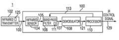
- FIG. 1is a functional block diagram of a system 1 for practicing some embodiments of the invention.
- System 1includes an infrared receiver 100 and an infrared transmitter 102 .
- Receiver 100includes an infrared sensor 104 , a band-pass filter 106 tuned to a center frequency 111 , a demodulator 108 , and a processor 110 .
- infrared sensor 104may receive from transmitter 102 an infrared signal 103 modulated at a carrier frequency 125 .
- Infrared sensor 104may generate an electric signal 105 that may have embedded control signals (i.e., a series of infrared sequences that correspond to certain commands).
- Band-pass filter 106may receive electric signal 105 and then transmit a filtered signal 107 to demodulator 108 .
- Demodulator 108may be configured to remove or separate carrier signal 123 from filtered signal 107 and output a clean digital control signal 121 to processor 110 .
- Processor 110may identify clean digital control signal 121 as corresponding to a predetermined transmission format and transmit a confirmation signal to band-pass filter 106 via feedback loop 113 . After receiving the confirmation signal, band-pass filter 106 may update center frequency 111 to operationally match the identified carrier frequency 125 .
- Processor 110may also generate an electronic signal 129 , which may be input into a logic circuit configured to perform some remote function (e.g., powering up a television).
- Infrared transmitter 102may be any device capable of generating infrared signals (e.g., infrared signal 103 ), such as a television remote control or any other handheld device equipped with an infrared light emitting diode. In some embodiments, infrared transmitter 102 may be configured to encrypt, modulate, and transmit control information, such as to infrared receiver 100 .
- Infrared sensor module 104may include any sensor capable of detecting infrared signals, such as infrared signal 103 modulated at carrier frequency 125 . Infrared sensor module 104 may also be configured to transmit electric signals, such as electric signal 105 , based on the infrared signal received.
- Band-pass filter 106may be any device configured to transmit a band of frequencies centered around center frequency 111 and to reject substantially all other frequencies.
- Center frequency 111may be set by, for example, a tri-state input, or by an analog input, or by I2C bus commands.
- Demodulator 108may be any device configured to remove or separate a control signal from a carrier signal.
- Processor 110may be a processor, an application-specific integrated circuit (ASIC), or any combination thereof.
- Processor 110may, for example, include circuitry configured to distinguish an actual transmission from other interfering transmissions, such as by comparing the received signal with a predetermined transmission format.
- Processor 110may also be configured to decode infrared signals. While infrared receiver 100 is illustrated with a single processor, those skilled in the art will appreciate that an infrared receiver may include multiple processors and/or coprocessors.
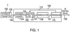
- FIG. 2is a schematic diagram of infrared signal 103 that may be received by some embodiments of the invention.
- infrared signal 103may have a predetermined transmission format including a digital control signal 121 and a carrier wave 123 generated at carrier frequency 125 .
- Carrier frequency 125may be set by infrared transmitter 102 .
- FIG. 3is a process diagram of an exemplary method 300 for operating a frequency-agile infrared receiver, such as infrared receiver 100 , according to some embodiments of the invention.
- an infrared sensormay receive an infrared signal modulated at a carrier frequency and then may generate a predetermined electric signal that includes control signals.
- infrared sensor 104may receive infrared signal 103 modulated at carrier frequency 125 and then generate a predetermined electric signal 105 .
- Signal 105may be fed to band-pass filter 106 , which may have a default center frequency 111 , such as 38 kHz.
- Infrared transmitter 102may have a different default carrier frequency 125 , such as 36 kHz.
- an infrared receiver with a center frequency of 38 kHzmay recognize signals transmitted from an infrared transmitter with a 36 kHz frequency if the distance between the transmitter and the receiver is sufficiently small (i.e., the strength of the infrared signal is sufficiently high).
- a band-pass filtermay reject all signals outside the pass-band centered on a certain center frequency and then feed a filtered signal to a demodulator.
- band-pass filter 106may reject signals outside the pass-band centered on center frequency 111 and may feed a filtered signal 107 to demodulator 108 .
- the demodulatormay demodulate the filtered signal and generate a clean digital control signal (i.e., without the carrier signal).
- demodulator 108may demodulate filtered signal 107 and generate a clean digital control signal 121 without carrier signal 123 .
- the digital control signal generated in step 305may be evaluated to determine whether it has a predetermined transmission format.
- processor 110may contain circuitry to determine whether digital control signal 121 contains a threshold number of bytes that are received and understood. This technique may be useful to distinguish actual infrared transmissions from noise. If the threshold number of bytes is not recognized, for example, then digital control signal 121 may be considered noise, rather than an intentional control signal transmission, and method 300 ends. If the threshold number of bytes is recognized and understood, digital control signal 121 may be decoded in step 310 , which translates the series of infrared sequences represented by digital control signal 121 into certain commands.
- the processormay feed back to the band-pass filter with a confirmation signal to update the band-pass center frequency.
- the confirmation signalmay include an indication that a predetermined transmission format has been received.
- processor 110may feed back to band-pass filter 106 via feedback loop 113 .
- the band-pass filtermay compare the carrier frequency to the center frequency to determine whether the center frequency should be updated. If the center frequency and carrier frequency are operationally equivalent, then process 300 ends without updating the center frequency. If the center frequency differs, operationally, from the carrier frequency, the center frequency may be updated in step 314 .
- band-pass filter 106may update center frequency 111 from 38 kHz to 36 kHz. Updating center frequency 111 may improve the sensitivity of infrared receiver 100 to infrared signals modulated at 36 kHz.
- the updated center frequencymay be stored in a non-volatile storage so that, if the receiver is powered up again, the center frequency is already set to the updated value.
- the inventionmay take the form of an entirely hardware embodiment or an embodiment containing both hardware and software elements.
- the inventionmay be implemented in software including, but not limited to, firmware, resident software, and microcode.
Landscapes
- Physics & Mathematics (AREA)
- Electromagnetism (AREA)
- Engineering & Computer Science (AREA)
- Computer Networks & Wireless Communication (AREA)
- Signal Processing (AREA)
- Optical Communication System (AREA)
- Selective Calling Equipment (AREA)
Abstract
Description
Claims (16)
Priority Applications (1)
| Application Number | Priority Date | Filing Date | Title |
|---|---|---|---|
| US12/234,587US8295711B2 (en) | 2008-09-19 | 2008-09-19 | Frequency-agile infrared receiver |
Applications Claiming Priority (1)
| Application Number | Priority Date | Filing Date | Title |
|---|---|---|---|
| US12/234,587US8295711B2 (en) | 2008-09-19 | 2008-09-19 | Frequency-agile infrared receiver |
Publications (2)
| Publication Number | Publication Date |
|---|---|
| US20100074631A1 US20100074631A1 (en) | 2010-03-25 |
| US8295711B2true US8295711B2 (en) | 2012-10-23 |
Family
ID=42037793
Family Applications (1)
| Application Number | Title | Priority Date | Filing Date |
|---|---|---|---|
| US12/234,587Expired - Fee RelatedUS8295711B2 (en) | 2008-09-19 | 2008-09-19 | Frequency-agile infrared receiver |
Country Status (1)
| Country | Link |
|---|---|
| US (1) | US8295711B2 (en) |
Families Citing this family (3)
| Publication number | Priority date | Publication date | Assignee | Title |
|---|---|---|---|---|
| US8213809B2 (en)* | 2009-01-23 | 2012-07-03 | Conexant Systems, Inc. | Universal systems and methods for determining an incoming carrier frequency and decoding an incoming signal |
| CN102347766A (en)* | 2011-07-08 | 2012-02-08 | 美芯集成电路(深圳)有限公司 | Novel infrared audio transmission transceiving system controlled by phase-locked loop |
| JP2019106575A (en)* | 2017-12-08 | 2019-06-27 | ルネサスエレクトロニクス株式会社 | Radio receiver and intermediate frequency signal generation method |
Citations (9)
| Publication number | Priority date | Publication date | Assignee | Title |
|---|---|---|---|---|
| US5684294A (en)* | 1996-10-17 | 1997-11-04 | Northern Telecom Ltd | Proximity and ambient light monitor |
| US5786921A (en) | 1994-08-15 | 1998-07-28 | Actisys Corporation | Infrared communication device for multistandard operations |
| US6049294A (en) | 1996-02-28 | 2000-04-11 | Samsung Electronics Co., Ltd. | Apparatus and method for adaptable receiving frequency selection in a remote control |
| US6812466B2 (en)* | 2002-09-25 | 2004-11-02 | Prospects, Corp. | Infrared obstacle detection in the presence of sunlight |
| US20050047794A1 (en) | 2003-08-29 | 2005-03-03 | Quintanar Felix Clarence | Infrared remote control receiver and system |
| US20050190073A1 (en) | 2004-02-20 | 2005-09-01 | Jon Berges | Noise resistant remote control system |
| US20070205914A1 (en) | 2006-03-03 | 2007-09-06 | Seong Cheol Choi | Remote operating apparatus and method of controlling the same |
| US7415264B2 (en)* | 2004-09-25 | 2008-08-19 | Skyworks Solutions, Inc. | Low noise filter for a wireless receiver |
| US20090306487A1 (en)* | 2006-04-11 | 2009-12-10 | The University Of Nottingham | Photoplethysmography |
- 2008
- 2008-09-19USUS12/234,587patent/US8295711B2/ennot_activeExpired - Fee Related
Patent Citations (9)
| Publication number | Priority date | Publication date | Assignee | Title |
|---|---|---|---|---|
| US5786921A (en) | 1994-08-15 | 1998-07-28 | Actisys Corporation | Infrared communication device for multistandard operations |
| US6049294A (en) | 1996-02-28 | 2000-04-11 | Samsung Electronics Co., Ltd. | Apparatus and method for adaptable receiving frequency selection in a remote control |
| US5684294A (en)* | 1996-10-17 | 1997-11-04 | Northern Telecom Ltd | Proximity and ambient light monitor |
| US6812466B2 (en)* | 2002-09-25 | 2004-11-02 | Prospects, Corp. | Infrared obstacle detection in the presence of sunlight |
| US20050047794A1 (en) | 2003-08-29 | 2005-03-03 | Quintanar Felix Clarence | Infrared remote control receiver and system |
| US20050190073A1 (en) | 2004-02-20 | 2005-09-01 | Jon Berges | Noise resistant remote control system |
| US7415264B2 (en)* | 2004-09-25 | 2008-08-19 | Skyworks Solutions, Inc. | Low noise filter for a wireless receiver |
| US20070205914A1 (en) | 2006-03-03 | 2007-09-06 | Seong Cheol Choi | Remote operating apparatus and method of controlling the same |
| US20090306487A1 (en)* | 2006-04-11 | 2009-12-10 | The University Of Nottingham | Photoplethysmography |
Also Published As
| Publication number | Publication date |
|---|---|
| US20100074631A1 (en) | 2010-03-25 |
Similar Documents
| Publication | Publication Date | Title |
|---|---|---|
| US20050053378A1 (en) | Interference resistant repeater systems including controller units | |
| US20110144778A1 (en) | Smart Audio Plug-in for Enabling Smart Portable Device to be Universal Remote Control | |
| US20160050516A1 (en) | A receiver, transceiver, transceiver module for a body coupled communication device, a body coupled communication system and a method of waking-up a body coupled receiver of a body coupled communication device | |
| CN102694597B (en) | Decoding method and controlling method of visible light signal | |
| US8295711B2 (en) | Frequency-agile infrared receiver | |
| MY205826A (en) | Packet detector/decoder for a radio transmission system | |
| US9867261B2 (en) | Light emitting device with dimming visible light communication function and interaction device applying for visible light | |
| JP2017041180A5 (en) | Program update control device, information home appliance, program update system, program update method and program | |
| CN100354902C (en) | Control method of remote control system and remote control system including radio frequency transceiver system | |
| CN104135682A (en) | Smart television remote control device having an infrared function, and method and remote controller of same | |
| EP2326016A3 (en) | Narrow-band interference detector, signal receiver employing narrow-band interference detector and controlling demodulator parameter setting according to narrow-band interference detection result, and related methods therefor | |
| US10194113B2 (en) | Switching circuit and switching method for video signal | |
| US7924167B2 (en) | Remote control code filtering used for relaying of remote control codes | |
| JP2014225853A (en) | Reception device and reception method for emergency alert broadcasting signal | |
| US10334670B2 (en) | Driver system | |
| EP1280310B1 (en) | Signal structure and scrambling for multicarrier transmission | |
| US20150295622A1 (en) | Wireless communication device and method of operating the same | |
| CN105915260B (en) | A kind of rf frequency transform method carrying RDS signal | |
| US10236990B2 (en) | Adding a keypad to a device configured with a wireless receiver | |
| JP5327679B2 (en) | Remote control device | |
| US20050075146A1 (en) | Apparatus and method for powering wireless inter-component audio transmission | |
| US20120257762A1 (en) | Communication system, receiving apparatus and communication method | |
| US20110026939A1 (en) | Infrared-receiving device with expanded module and receiving method for the same | |
| KR101000877B1 (en) | Electronic equipment having a remote control receiver and the remote control receiver | |
| KR100866388B1 (en) | Dual channel infrared receiver and dual channel infrared remote control system including the same |
Legal Events
| Date | Code | Title | Description |
|---|---|---|---|
| AS | Assignment | Owner name:SILVERBROOK RESEARCH PTY LTD,AUSTRALIA Free format text:ASSIGNMENT OF ASSIGNORS INTEREST;ASSIGNORS:RUSMAN, JAN;SILVERBROOK, KIA;LAPSTUN, PAUL;REEL/FRAME:021560/0726 Effective date:20080828 Owner name:SILVERBROOK RESEARCH PTY LTD, AUSTRALIA Free format text:ASSIGNMENT OF ASSIGNORS INTEREST;ASSIGNORS:RUSMAN, JAN;SILVERBROOK, KIA;LAPSTUN, PAUL;REEL/FRAME:021560/0726 Effective date:20080828 | |
| AS | Assignment | Owner name:APPLE INC.,CALIFORNIA Free format text:ASSIGNMENT OF ASSIGNORS INTEREST;ASSIGNOR:MAHOWALD, PETER H.;REEL/FRAME:021710/0807 Effective date:20080917 Owner name:APPLE INC., CALIFORNIA Free format text:ASSIGNMENT OF ASSIGNORS INTEREST;ASSIGNOR:MAHOWALD, PETER H.;REEL/FRAME:021710/0807 Effective date:20080917 | |
| FEPP | Fee payment procedure | Free format text:PAYOR NUMBER ASSIGNED (ORIGINAL EVENT CODE: ASPN); ENTITY STATUS OF PATENT OWNER: LARGE ENTITY | |
| ZAAA | Notice of allowance and fees due | Free format text:ORIGINAL CODE: NOA | |
| ZAAB | Notice of allowance mailed | Free format text:ORIGINAL CODE: MN/=. | |
| STCF | Information on status: patent grant | Free format text:PATENTED CASE | |
| FPAY | Fee payment | Year of fee payment:4 | |
| MAFP | Maintenance fee payment | Free format text:PAYMENT OF MAINTENANCE FEE, 8TH YEAR, LARGE ENTITY (ORIGINAL EVENT CODE: M1552); ENTITY STATUS OF PATENT OWNER: LARGE ENTITY Year of fee payment:8 | |
| FEPP | Fee payment procedure | Free format text:MAINTENANCE FEE REMINDER MAILED (ORIGINAL EVENT CODE: REM.); ENTITY STATUS OF PATENT OWNER: LARGE ENTITY | |
| LAPS | Lapse for failure to pay maintenance fees | Free format text:PATENT EXPIRED FOR FAILURE TO PAY MAINTENANCE FEES (ORIGINAL EVENT CODE: EXP.); ENTITY STATUS OF PATENT OWNER: LARGE ENTITY | |
| STCH | Information on status: patent discontinuation | Free format text:PATENT EXPIRED DUE TO NONPAYMENT OF MAINTENANCE FEES UNDER 37 CFR 1.362 | |
| FP | Lapsed due to failure to pay maintenance fee | Effective date:20241023 |