US8295523B2 - Energy delivery and microphone placement methods for improved comfort in an open canal hearing aid - Google Patents
Energy delivery and microphone placement methods for improved comfort in an open canal hearing aidDownload PDFInfo
- Publication number
- US8295523B2 US8295523B2US12/244,266US24426608AUS8295523B2US 8295523 B2US8295523 B2US 8295523B2US 24426608 AUS24426608 AUS 24426608AUS 8295523 B2US8295523 B2US 8295523B2
- Authority
- US
- United States
- Prior art keywords
- transducer
- ear
- microphone
- canal
- ear canal
- Prior art date
- Legal status (The legal status is an assumption and is not a legal conclusion. Google has not performed a legal analysis and makes no representation as to the accuracy of the status listed.)
- Active, expires
Links
Images


Classifications
- H—ELECTRICITY
- H04—ELECTRIC COMMUNICATION TECHNIQUE
- H04R—LOUDSPEAKERS, MICROPHONES, GRAMOPHONE PICK-UPS OR LIKE ACOUSTIC ELECTROMECHANICAL TRANSDUCERS; DEAF-AID SETS; PUBLIC ADDRESS SYSTEMS
- H04R25/00—Deaf-aid sets, i.e. electro-acoustic or electro-mechanical hearing aids; Electric tinnitus maskers providing an auditory perception
- H04R25/65—Housing parts, e.g. shells, tips or moulds, or their manufacture
- H04R25/652—Ear tips; Ear moulds
- H—ELECTRICITY
- H04—ELECTRIC COMMUNICATION TECHNIQUE
- H04R—LOUDSPEAKERS, MICROPHONES, GRAMOPHONE PICK-UPS OR LIKE ACOUSTIC ELECTROMECHANICAL TRANSDUCERS; DEAF-AID SETS; PUBLIC ADDRESS SYSTEMS
- H04R25/00—Deaf-aid sets, i.e. electro-acoustic or electro-mechanical hearing aids; Electric tinnitus maskers providing an auditory perception
- H04R25/60—Mounting or interconnection of hearing aid parts, e.g. inside tips, housings or to ossicles
- H04R25/604—Mounting or interconnection of hearing aid parts, e.g. inside tips, housings or to ossicles of acoustic or vibrational transducers
- H—ELECTRICITY
- H04—ELECTRIC COMMUNICATION TECHNIQUE
- H04R—LOUDSPEAKERS, MICROPHONES, GRAMOPHONE PICK-UPS OR LIKE ACOUSTIC ELECTROMECHANICAL TRANSDUCERS; DEAF-AID SETS; PUBLIC ADDRESS SYSTEMS
- H04R2225/00—Details of deaf aids covered by H04R25/00, not provided for in any of its subgroups
- H04R2225/021—Behind the ear [BTE] hearing aids
- H04R2225/0213—Constructional details of earhooks, e.g. shape, material
- H—ELECTRICITY
- H04—ELECTRIC COMMUNICATION TECHNIQUE
- H04R—LOUDSPEAKERS, MICROPHONES, GRAMOPHONE PICK-UPS OR LIKE ACOUSTIC ELECTROMECHANICAL TRANSDUCERS; DEAF-AID SETS; PUBLIC ADDRESS SYSTEMS
- H04R25/00—Deaf-aid sets, i.e. electro-acoustic or electro-mechanical hearing aids; Electric tinnitus maskers providing an auditory perception
- H04R25/65—Housing parts, e.g. shells, tips or moulds, or their manufacture
- H04R25/658—Manufacture of housing parts
Definitions
- the present inventionrelates generally to hearing systems, devices, output transducer supports, and methods. More particularly, the present invention is directed to hearing systems that comprise an elongate support adapted to minimize contact with the ear while the transducer is positioned near the user's eardrum, thereby providing improved comfort to the user.
- the systemsmay be used to enhance the hearing process of those that have normal or impaired hearing with comfort.
- hearing aidsPeople who wear hearing aids would like hearing aids with certain characteristics, such as cosmetic appeal, comfort and sound quality. With respect to comfort, hearing aids are often used for prolonged periods of time and people generally do not want to use a device that is uncomfortable. Although the importance of cosmetics will vary among individuals, people generally have a desire to hide a handicap such as a hearing deficit. Amplified sound quality is also important, in particular restoring the ears natural ability to detect sound localization cues at high frequencies. Although current hearing aids provide some benefit to the user, the above characteristics are generally not all satisfied with a single device.
- BTE aidsEarly hearing aids included behind the ear hearing aides (hereinafter “BTE aids”) that placed much of the hearing aid electronics, for example the microphone and speaker, behind the ear. Although BTE aides provided somewhat improved hearing, these aids were readily apparent on the user and not cosmetically attractive. Advancements in electronics technology provided smaller components that led to the development of the completely in canal hearing aid (hereinafter “CIC aids”).
- CIC aidshave desirable cosmetics because the device is generally deep in the canal and not visible. However, these devices can be uncomfortable due to jaw movements, and the user's own voice can sound hollow and unnatural.
- ventscan be placed in the CIC device that allows sound waves to pass through the device.
- ventscan improve the sound quality of the user's own voice, vents can also cause unwanted feedback, which produces a whistling sound.
- a potential problem with hearing aids that place the microphone behind the pinna of the earis that directionally dependent sound localization cues, for example in the 6 to 12 kHz frequency range, may not be present in the amplified signal.
- directionally dependent sound localization cuesfor example in the 6 to 12 kHz frequency range
- these localization cuesare important for understanding speech, for example speech of a desired person in the presence of additional people who are also speaking.
- the microphoneis often near a sound emitting transducer, such as a speaker, so that feedback can result.
- open canal hearing aidscan provide improved comfort, these devices have generally been deficient with respect to other desired characteristics. For example, some open canal hearing aids use external electronics, for example microphones and speakers such that these devices may not be cosmetically appealing. Also, open canal hearing aids have generally had limited success in providing frequency dependent sound localization cues. Open canal hearing aids are described in U.S. Pat. No. 5,987,146 and have been sold under the name of ReSound AiR, available from GN ReSound North America, Bloomington, Minn. Several modifications and refinements have been made to the original open canal hearing aids, for example as described in U.S. Pat. No. 5,606,621 and U.S. Pub. Nos. US 2005/0078843 and 2005/0190939, and open canal hearing aids are commercially available, for example from Vivatone Hearing Systems LLC of Shelton Conn.
- Hearing aids with the sound sensitive microphone positioned in the ear canalshow some promise of potentially providing sound localization cues.
- placement of the microphone in the canal of an acoustic hearing aid which uses a sound generating speaker positioned in the ear canalcan produce significant feedback.
- many open canal acoustic hearing aidsdo not use a microphone in the ear canal.
- the amplification gain of a hearing aid devicecan be decreased to reduce feedback, decreasing the gain can also make it harder for a user to hear weak sounds, which is contrary to the purpose of wearing a hearing aid device. Because of this feedback that generally precludes placement of the microphone in the ear canal, many acoustic hearing aids do not provide directionally dependent sound localization cues.
- One approach to providing sound localization cueshas been to provide a directional microphone instead of an omni-directional microphone. However in at least some instances, devices using directional microphones have met with only limited success.
- the eardrumcan be driven electromagnetically with a magnet placed on the ear so as to reduce the acoustic feedback to the ear canal microphone as discussed in U.S. Pat. Nos. 5,259,032; 5,276,910; and 5,425,104; as well as U.S. patent application Ser. No. 11/121,517 and U.S. Patent Application Publication No. 2006/0023908, entitled “Transducer for Electromagnetic Hearing Devices”.
- Such devicestypically use a coil wrapped around a core (hereinafter “core/coil”) to transmit electromagnetic energy from the coil to the magnet positioned on the ear structure.
- One difficulty encountered with hearing aid devices that use a coil to electromagnetically drive a magnet positioned on the eardrum, stapes or other ear structureis that such devices can be uncomfortable for the user. Work in relation with the present invention suggests that this discomfort is associated with placement of the coil deep within the ear canal near the eardrum.
- this placement near the eardrumis desirable as the coil is near the magnet positioned on the ear structure so that electromagnetic energy can be effectively coupled to the magnet.
- the coilshould be held accurately to avoid damage to the eardrum.
- an ear canal shellcan be used to hold the core/coil in place deep within the ear canal.
- the shellcan be customized specific to each user, for example molded, and have openings to provide an open canal hearing aid design, such devices have provided less than ideal results.
- userscan experience skin irritation, discomfort, and even ear pain due to friction between the shell and the canal skin. Friction can arise from speech production, mastication, and swallowing, potentially causing irritation and discomfort.
- present coil designs for electromagnetically driven eardrum magnet hearing aidsmay be less than ideal.
- the size requirements of the coilare dictated by electromagnetic field requirements (B fields) to drive the magnet.
- B fieldselectromagnetic field requirements
- the size of the coil of such devicesmay be larger than necessary and contribute to user discomfort.
- the present inventionprovides hearing systems, devices, output transducer supports, and methods that improve user comfort and position a transducer deep in the ear canal.
- the output transducer supports, devices and hearing systems of the present inventionmay comprise an elongate support adapted to minimize, and even avoid, contact with the ear while the transducer is positioned near the user's eardrum, thereby avoiding frictional contact with the ear and providing improved comfort for the user.
- the supportcomprises a flexible support that can bend and/or flex in response to user movement, so as to provide comfort to the user.
- embodiments of the present inventionprovide a hearing aid device for placement in an ear of a user.
- the devicecomprises an elongate support and an energy delivery transducer.
- the elongate supporthas a proximal portion and a distal end.
- the energy delivery transduceris attached to the elongate support near the distal end.
- the supportis adapted to position the transducer near an eardrum while the proximal portion is placed at the location near an ear canal opening.
- An intermediate portion of the elongate supportis sized to minimize contact with the ear between the proximal portion and distal end.
- the elongate supportincludes specific adaptations to provide user comfort.
- the elongate supportis adapted to at least partially support the transducer from the proximal portion, thereby reducing support of the transducer by the ear within the canal.
- the intermediate portionextends along at least about 50% of a distance from the proximal portion to the distal end, and the distance corresponds to a distance of a canal of the ear, thereby avoiding contact with the ear along much of the support.
- the elongate supporthas a cross sectional width, for example a diameter, less than a cross sectional width, for example a diameter, of the transducer.
- the elongate supportis adapted to flex in response to user movement for improved comfort, for example jaw movement, which decreases pressure on the ear within the canal when the user moves, and the elongate support is adapted to conduct heat from the energy delivery transducer.
- a positioneris attached to the elongate support near the transducer and is adapted to contact the ear in the canal near the transducer and support the transducer.
- the positionercan include specific adaptations to provide user comfort.
- the positionercan be sufficiently wide to contact the ear in the canal so as to support the transducer, and the positioner can include a flexible portion adapted to bend while the positioner is positioned in the canal.
- the positioneris often adapted to suspend and center the transducer in the canal to avoid transducer to ear contact while the positioner contacts the ear.
- the positionerincludes openings formed thereon to pass sound waves through the openings.
- the positionercan include flanges, petals or spokes that define the openings.
- the positionerincludes an outer boundary that can be oval, circular, or even molded to the user's ear, and is adapted to engage the canal while the positioner suspends the transducer in the canal.
- the positionercan be tapered proximally to facilitate insertion into the canal. Often, the positioner will comprise a thickness no more than a length of the transducer.
- the transduceris adapted for user comfort.
- the transducerhas a width of no more than about 4 mm, thereby avoiding contact with the ear.
- the transducercan be adapted to transmit electromagnetic energy toward the eardrum to stimulate a magnet suspended on the eardrum and/or an ossicle, other forms of energy, for example ultrasound, can be transmitted toward the eardrum.
- the transducercan be a coil adapted to transmit electromagnetic energy toward the eardrum with frequency components in the audio range, other frequencies of electromagnetic energy can be used, for example optical and radio frequencies.
- the transducercomprises a coil.
- the coilcomprises a length from about 3 to 6 mm and a width from about 3 to 4 mm.
- the coilis adapted to drive a magnet positioned on an eardrum while a distal end of the coil is positioned a distance from about 2 to 6 mm from the eardrum.
- the transduceris adapted to transmit electromagnetic energy toward the eardrum, and the electromagnetic energy comprises optical frequencies.
- Many embodimentsinclude a microphone attachable to the support near the proximal portion of the support to position the microphone near the opening to the ear canal.
- the microphoneis adapted to generate an electrical signal in response to an audio signal.
- a processor connected to the microphoneis adapted to modify the audio signal from the microphone with a transform function and apply the modified audio signal to the transducer to stimulate the ear.
- the processor and a battery to power the processorcan be adapted to be worn behind a pinna of the ear.
- the microphonecan be attached to the support to position the microphone within about 6 mm of the opening to the canal.
- the elongate supportdefines an enclosure, and a microphone is positioned within the enclosure.
- the intermediate portionmay comprise the enclosure, and the microphone may be positioned within the intermediate portion.
- the elongate supportcomprises at least one opening and the microphone is configured to measure a sound pressure of the ear canal through at least one opening.
- the elongate supportmay comprise a flexible tube and the enclosure may comprise a lumen of the tube.
- the energy delivery transducercomprises a coil assembly positioned within the enclosure.
- An opening of the microphonecan be positioned no more than about 12 mm from a proximal end of the coil to measure a sound pressure of the ear canal near the eardrum.
- the microphoneis adapted to be worn behind a pinna of the ear, and the microphone comprises a probe tube that extends to the ear canal opening; the probe tube has an opening near the ear canal opening such that the microphone detects sound from the ear canal opening.
- embodiments of the present inventionprovide a hearing aid system for use with an ear.
- the systemcomprises a microphone, a processor, a transducer and a flexible elongate support.
- the microphoneis adapted to generate a signal.
- the processorconnected to the microphone and adapted to apply a transform function to the signal to produce a transformed signal.
- the transduceris adapted to receive the transformed signal and emit electromagnetic energy in response to the transformed signal.
- the flexible elongate supportincludes a proximal portion and a distal end.
- the flexible elongate supportextends at least from the proximal portion to the distal end, and the proximal portion is adapted for placement near an opening of an ear canal.
- the distal endis adapted to support the transducer near an eardrum while the proximal portion is placed near the opening.
- an intermediate portion of the elongate support located between the proximal portion and the distal endis sized to avoid contact with the ear.
- the elongate supportis adapted to suspend the transducer in the ear canal to avoid contact with the ear.
- a positionercan be attached to the elongate support near the transducer, the wide is support adapted to engage the canal of the ear to suspend the transducer in the canal to avoid transducer to ear contact while the proximal portion is placed near the opening of the canal.
- the microphoneis disposed near the proximal portion to position the microphone near the opening to the ear canal when the proximal portion is placed near the opening.
- the supportcan be adapted to position the microphone within about 6 mm of the opening and position a distal end of the transducer from about 2 to 6 mm from the eardrum, while the proximal portion is placed near the opening.
- the elongate supportdefines an enclosure, and a microphone is positioned within the enclosure.
- the intermediate portionmay comprise the enclosure and the microphone can be positioned within the intermediate portion.
- the elongate supportmay comprise at least one opening, and the microphone may be configured to measure a sound pressure of the ear canal through the at least one opening.
- the elongate supportmay comprise a flexible tube and the enclosure may comprise a lumen of the tube.
- the energy delivery transducermay comprise a coil positioned within the enclosure, and an opening of the microphone may be no more than about 12 mm from a proximal end of the coil to measure a sound pressure of the ear canal near the eardrum.
- a magnetis adapted for placement on the eardrum, and the magnet adapted to receive the electromagnetic energy from the transducer to drive the eardrum and stimulate the ear.
- the microphoneis often placed near the opening to the ear canal or within the ear canal, the microphone can be adapted to be worn behind a pinna of the ear with a tube having an opening within about 6 mm of the ear canal opening.
- embodiments of the present inventioncomprise a method of fitting a hearing aide device to a user.
- a transducer, a microphone and elongate support for placement in an ear canal of the userare provided.
- a user characteristicis measured.
- the measured user characteristicis one that is correlated with a distance from an opening of an ear canal to the user's tympanic membrane.
- a length along the elongate supportis determined based on the measured characteristic to position the transducer near the tympanic membrane when the support is placed in the ear canal.
- the lengthis determined before the support is placed in the ear canal.
- the lengthis determined to position the transducer near the tympanic membrane when the support is placed in the ear canal.
- a size of a positioneris determined for placement in the ear canal near the transducer.
- the positioneris sized to contact the ear to support and center the transducer in the ear canal and avoid contact between the transducer and the ear.
- the length of the elongate supportis determined to position the transducer from about 2 to 6 mm from the tympanic membrane.
- the length along the elongate supportis determined to position the microphone near the opening of the ear canal when the support is placed in the ear canal.
- the microphonecan be positioned at the location along the support to position the microphone within about 6 mm of the opening of the ear canal while the transducer is positioned near the tympanic membrane, and the microphone can be positioned in response to the length of the elongate support.
- the elongate supportdefines an enclosure, and a microphone is positioned within the enclosure.
- the intermediate portionmay comprise the enclosure and the microphone can be positioned within the intermediate portion.
- the elongate supportmay comprise at least one opening, and the microphone may be configured to measure a sound pressure of the ear canal through the at least one opening.
- the elongate supportmay comprise a flexible tube and the enclosure may comprise a lumen of the tube.
- the energy delivery transducermay comprise a coil positioned within the enclosure, and an opening of the microphone may be about 12 mm or less from a proximal end of the coil to measure a sound pressure of the ear canal near the eardrum.
- the length of the elongate supportis determined to minimize contact with the ear between the microphone and the transducer.
- inventions of the present inventionprovide an energy delivery transducer for use in an ear canal with a hearing aid.
- the transducercomprises a coil assembly and a biocompatible coating.
- the coil assemblycomprises a wire with turns adapted to generate a magnetic field.
- the coil assemblyhas a length from about 3 to 6 mm and a maximum cross sectional width from about 3 to 4 mm.
- the coil assemblyis adapted for placement in the canal of the ear to permit sound waves to travel along the canal past the coil between the coil and the canal.
- the biocompatible coatingis disposed on and around the coil to protect the ear.
- the coilincludes a number of turns and the number of turns is from about 100 to about 450 turns.
- the wirecomprises a gauge in a range from about 36 to about 44 gauge, although the range can be narrower, for example from about 38 to 42.
- the coil assemblycomprises a length from about 3 to 6 mm, although the length can be from about 3.5 to 5 mm, for example 4 about mm.
- the coil assemblycomprises a width from about 1 to about 4 mm, for example from about 3.2 to about 4.2 mm.
- the transducercan include a core with the wire placed around the core with turns of the wire.
- the corecan include a maximum cross sectional width from about 0.5 to about 3.3 mm, for example from about 1.5 to 3.3 mm.
- a modular hearing aid assemblyfor use with an ear of a user.
- the assemblycomprises a behind the ear component.
- the behind the ear componentcomprises a battery and a processor, and the behind the ear component sized to fit at least partially behind a pinna of the user.
- An elongate canal componentcomprises a coil assembly shaped to fit in an ear canal and adapted to transmit electromagnetic energy toward and drive a magnet suspended on an eardrum and/or an ossicle of the user.
- the elongate canal componentis adapted to flex in response to user movement.
- An elongate pinna componenthas a first end configured to connect to the behind the ear component and a second end configured to connect to the transducer component.
- the elongate canal componentcomprises an annular section adapted to flex in response to user movement.
- the elongate pinna componentmay comprise a first connector on the first end adapted to mate with a connector on the behind the ear component and a second connector on the second end adapted to mate with a connector on the canal component.
- a length of the elongate pinna component and a length of the elongate canal componentare each sized to fit the user.
- the elongate pinna componentcomprises a flexible tubing having wires disposed therein.
- the flexible tubingmay comprise plastic and the wires can be sized to support the pinna component.
- the wires sized to support the pinna componentcan transmit electrical energy from the behind the ear component to the elongate transducer component.
- the elongate pinna componentcomprises a microphone located near the second end to detect sound near an opening of the ear of the user.
- the elongate pinna componentcomprises an elongate tube adapted to conduct sound from an opening in the user's ear near the second end to a microphone positioned near the first end, such that the microphone detects sound from the opening in the user's ear with sound conducted along the elongate tube.
- the microphonecan be located in the behind the ear component, and the elongate tube can extend to the microphone.
- embodiments of the present inventionprovide a method of fitting a hearing aid device to an ear of a user.
- An elongate pinna componentis selected, in which the selected elongate pinna component has a length related to a distance from an opening in the users ear to an upper portion of a pinna of the user.
- An elongate ear canal componentis selected in which the elongate ear canal component has a length related to a length of a canal of the ear of the user.
- the pinna componentis selected from among at least two sizes of pinna components, and the canal component is selected from among at least two sizes of canal components.
- the pinna componentcan be selected from among at least three sizes of pinna components, and the canal component can be selected from among at least three sizes of canal components.
- the pinna componentis selected based on a size of the pinna and the canal component is selected based on a size, for example a length, of the user's canal.
- embodiments of the present inventionprovide a hearing aid device for placement in an ear of a user.
- the devicecomprises an elongate support having a proximal portion and a distal end.
- An energy delivery transduceris coupled to the elongate support to transmit electromagnetic energy comprising optical frequencies from the distal end.
- a positioneris coupled to the elongate support and configured to position the distal end within the ear canal.
- the energy delivery transducercomprises at least one of a light emitting diode or a laser diode coupled to the proximal portion of the elongate support to transmit optical energy to the distal end.
- the elongate supportmay comprise at least one waveguide, for example a single waveguide or a plurality of two or more waveguides, configured to transmit optical energy at least from the proximal portion to the distal end.
- the supportcan be adapted to position the distal end near an eardrum when the proximal portion is placed at a location near an ear canal opening.
- An intermediate portion of the elongate supportcan be sized to minimize contact with a canal of the ear between the proximal portion to the distal end.
- FIG. 1Ashows a hearing aid device with an elongate support with the transducer positioned near an eardrum of a user, according to embodiments of the present invention
- FIG. 1Bshows a medial view of a hearing aid device as in FIG. 1A , according to embodiments of the present invention
- FIG. 1Cshows a schematic illustration of a hearing aid device as in FIGS. 1A and 1B in greater detail, according to embodiments of the present invention
- FIG. 1Dshows a simplified schematic illustration of a hearing system that includes an in input transducer assembly, a transmitter assembly, and an output transducer assembly, according to embodiments of the present invention
- FIG. 1Eis a more detailed schematic illustration of a hearing system as in FIG. 1D , according to embodiments of the present invention.
- FIG. 2Ashows a positioner attached to an elongate support near a transducer, in which the positioner is adapted to contact the ear in the canal near the transducer and support the transducer, according to embodiments of the present invention
- FIG. 2Bshows a positioner as in FIG. 2A in detail, according to embodiments of the present invention
- FIG. 3shows transducer comprising a coil of wire wrapped around an iron core, according to embodiments of the present invention
- FIG. 4Ashows a table of coil design parameters shown to provide suitable coil characteristics including suitable coil diameters and wire gauges, according to embodiments of the present invention
- FIG. 4Bshows the number of wire turns available for a coil assembly having parameters as shown FIG. 4A , according to embodiments of the present invention
- FIGS. 5A to 5Fshow coil properties for a coil assembly having parameters as shown in FIG. 4A , according to embodiments of the present invention
- FIG. 6shows tradeoffs in the design variables for three different coils with 4 mm length cores, according to embodiments of the present invention
- FIG. 7shows a method of fitting and placing components of a hearing aid in an ear of a user, according to embodiments of the present invention
- FIG. 8Ashows an elongate support with a pair of positioners adapted to contact the ear canal and support the transducer, according to embodiments of the present invention
- FIG. 8Bshows an elongate support as in FIG. 8A attached to two positioners placed in an ear canal, according to embodiments of the present invention
- FIG. 8B-1shows an elongate support configured to position a distal end of the elongate support with at least one positioners placed in an ear canal, according to embodiments of the present invention
- FIG. 8Cshows a positioner adapted for placement near the opening to the ear canal, according to embodiments of the present invention
- FIG. 8Dshows a positioner adapted for placement near the coil assembly, according to embodiments of the present invention.
- FIG. 9Ashows a schematic illustration of a hearing aid device with modular inter-connectable components to customize the device to the dimensions of the user, according to embodiments of the present invention
- FIG. 9Bshows an isometric view of the hearing aid device as in FIG. 9A , according to embodiments of the present invention.
- FIG. 9Cshows a cross sectional view of the hearing aid device as in FIGS. 9A and 9B , according to embodiments of the present invention.
- FIG. 9Dshows a partial cut away view of hearing aide device with the microphone and coil assembly positioned inside an elongate support comprising a sleeve, according to embodiments of the present invention
- FIG. 9Eshows a hearing aid device with a tube along the elongate pinna component to conduct sound from the ear canal opening to a microphone positioned away from the ear canal opening, according to embodiments of the present invention.
- FIG. 10shows a method of selecting components to fit a user with components as in FIGS. 9A to 9E , according to embodiments of the present invention.
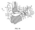
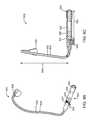
- FIG. 1Ashows a hearing aid device with an elongate support 50 with a transducer is positioned near an eardrum of a user, according to embodiments of the present invention.
- An ear 10includes a pinna 15 and an ear canal 11 .
- Ear canal 11extends laterally to an opening 17 , which is an entrance to the ear canal from outside the user.
- the outer earcomprises pinna 15 and ear canal 11 .
- Ear canal 11extends medially to a tympanic membrane 16 (eardrum).
- Tympanic membrane 16is mechanically coupled to three bones: a malleus 18 (hammer), an incus 20 (anvil) and a stapes 22 (stirrup).
- the malleusis coupled to the tympanic membrane.
- the middle earcomprises the tympanic membrane and the ossicles.
- the inner earcomprises a cochlea 24 , a spiral structure.
- the stapes 22is coupled to the cochlea 24 so that acoustic energy is transmitted from the tympanic membrane to the inner ear via the ossicles.
- Several components of the hearing aid deviceare attached to elongate support 50 .
- a microphone 44is shown attached to elongate support 50 near opening 17 .
- a coil assembly 40is shown supported by elongate support 50 .
- Coil assembly 40includes a coil of wire wrapped around a ferromagnetic core and a biocompatible coating.
- Coil assembly 17is an energy delivery transducer that converts electrical current to a magnetic field. The magnetic field is transmitted a permanent magnet 28 .
- Permanent magnet 28is positioned on a support component 30 that is removably attached to tympanic membrane 16 . The magnetic field transmitted to permanent magnet 28 applies a force to the tympanic membrane.
- the applied forcecauses tympanic membrane 16 to move in a manner similar that which occurs when sound impinges on the tympanic membrane in the normal manner.
- Magnet 28 and support component 30are available from available from EarLens Corporation of Redwood City, Calif.
- a magnet and/or a magnetic materialis attached to at least one of the malleus, the incus and the stapes, and coil assembly 17 is used to drive the magnet and/or magnetic material.
- Elongate support 50functions as a scaffolding to hold the microphone and coil assembly in place.
- Elongate support 50includes structures that allow the support to hold the energy delivery transducer and microphone in place while permitting elongate support 50 to flex and/or bend to accommodate user motion and individual user characteristics.
- Elongate support 50can comprise a tube to hold the wires for transducers, for example microphone 44 and coil assembly 40 .
- the elongate supportcan include a flexible cable, for example a cable formed from the wires electrically connected to a transducer such as coil 40 .
- Coil assembly 40is attached near the end of elongate support 50 .
- Elongate support 50is shaped to position a distal end of coil assembly 40 from about 2 to 6 mm from tympanic membrane 16 , for example about 4 mm from tympanic membrane 16 .
- Coil assembly 40is adapted to electromagnetically drive permanent magnet 28 while a distal end of coil assembly 40 is positioned from 2 to 6 mm from tympanic membrane 16 , for example 4 mm from tympanic membrane 16 .
- microphone 44is attached to elongate support 50 and positioned inside ear canal 11 near opening 17 .
- This placement of microphone 44permits detection of high frequency sound localization cues.
- Microphone 44is attached to the elongate support using an adhesive 46 that can comprise any commercially available adhesive.
- Other embodimentsuse other forms of attachment of microphone 44 to elongate support 50 , for example a collar that wraps around elongate support 50 and holds microphone 44 in place with friction.
- microphone 44can be slid along elongate support 50 to position the microphone along elongate support 50 at a desired location.
- Microphone 44comprises any of the commercially available types, for example electret type, condenser type, and piezoelectric type including polyvinylidene fluoride polymer (herein after “PVDF”).
- PVDFpolyvinylidene fluoride polymer
- Another microphone type that can be usedis the optical microphone which may reduce electromagnetic interference.
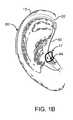
- FIG. 1Bshows a medial view of a hearing aid device as in FIG. 1A , according to embodiments of the present invention.
- a behind the ear (BTE) driver unit 80includes electronic components coupled to microphone 44 and coil assembly 40 , for example amplifiers, a digital signal processor (hereinafter “DSP”) unit and batteries.
- DSPdigital signal processor
- Driver unit 80includes an ear hook 82 that attaches near the top of pinna 15 .
- Driver unit 80is connected to elongate support 50 . As shown in FIGS. 1A and 1B , sound entering the ear canal is captured by microphone 44 and then sent to the DSP unit located in driver unit 80 .
- driver unit 80is shown to extend slightly beyond an outer boundary pinna 15 so as to be visible from the side of the user, driver unit 80 can be made compact to fit within the outer boundary of pinna 15 so that the driver unit is not visible from the side of the user.
- FIG. 1Cshows a schematic illustration of a hearing aid device as in FIGS. 1A and 1B in greater detail.
- Support 50extends from ear hook 82 of driver unit 80 to coil assembly 40 .
- Support 50has embedded therein a wire 70 and a wire 72 .
- Wire 70 and wire 72are electrically connected to coil assembly 40 to drive coil assembly 40 with electrical current.
- Coil assembly 40includes a core 78 and a coil 79 .
- Coil 79comprises several turns of wire wrapped around core 78 .
- Wire 70 and wire 72are shielded with a shielding 73 .
- Shielding 73is an electrical conductor attached to support 50 .
- Shielding 73can be formed in any number of known ways including braided wire and thin metallic tubing positioned over wire 70 and wire 72 to attenuate, and ideally eliminate, electromagnetic interference emanating from wire 70 and wire 72 that can interfere with the signal from microphone 44 .
- wires 70 and 72can be twisted to form a twisted pair.
- Shielding 73also includes a biocompatible coating to protect the ear and elongate support 50 .
- Microphone 44is attached to support 50 with adhesive 46 as described above.
- At least one wire 76extends from microphone 44 to provide an audio signal to driver unit 80 .
- At least one wire 76comprises a twisted pair of wires to reduce sensitivity noise.
- At least one wire 76is shown external to elongate support 50 in FIG. 1C . In alternate embodiments at least one wire 76 is embedded within external support 50 . In alternate embodiments microphone 44 is connected to wire 72 while 72 provides a reference ground voltage, and at least one wire 76 comprises one wire that transmits an electrical audio signal from microphone 44 .
- Elongate support 50also comprises a resilient member 74 .
- Resilient member 74has properties that provide improved patient comfort with elongate support 50 .
- the mechanical properties of elongate support 50are substantially determined by the properties of resilient member 74 , for example resilience, flexure and deformation properties.
- Resilient member 74is elastically flexible in response to small deflections, such as patient chewing and other patient movements. Additionally, resilient member 74 can be deformed to a desired shape that matches the user's ear canal with larger deflections so as to permit resilient member 74 to be deformed to a shape that corresponds to the user's ear canal so as to avoid frictional contact between coil assembly 40 and the user's ear.
- resilient member 74is formed from a heat conducting material to transport heat away from core 78 , for example metal and/or carbon materials.
- One ordinary skillcan select appropriate materials with appropriate shapes to provide resilient member 74 , for example wires of appropriate gauge and material.
- Resilient member 74conducts heat away from core 78 and out of the ear canal to provide improved patient comfort. As illustrated in FIG. 1C , resilient member 74 extends beyond opening 17 to ear hook 82 of driver unit 80 . Resilient member 40 attaches to core 78 at attachment locus 77 . Attachment locus 77 is adapted to conduct heat from core 78 to resilient member 74 .
- attachment locus 77can comprise a metallic weld, solder, or a thin layer of heat conducting adhesive material to promote heat conduction through the attachment locus.
- resilient member 74 and core 78are formed from the same piece of material; this improves heat conduction and decreases the probability of device failure caused by separation of resilient member 74 from core 78 .
- wires 70 and 72are resilient support members formed of resilient metal to provide resilient support, in a manner similar to that described above with respect to resilient member 74 .
- wires 70 and 72can be sized to provide very little support, for example with wires having a small diameter.
- the resilient supportis disposed near the outside of the elongate support and comprises resilient tubing.
- FIG. 1Dshows a simplified schematic illustration of a hearing system 110 that includes an in input transducer assembly 142 , a transmitter assembly 144 , and an output transducer assembly 126 , according to embodiments of the present invention.
- Input assembly 142includes microphone 44
- transmitter assembly 144can include a processor to process signals from microphone 44 and may include the energy delivery transducer, for example coil assembly 40 .
- Output transducer assembly 126includes permanent magnet 28 .
- output transducer assembly 126may comprise the energy delivery transducer, for example coil assembly 40 .
- Input transducer assembly 142will receive a sound input, typically either ambient sound, for example microphone 44 in the case of hearing aids for hearing impaired individuals, or an electronic sound signal from a sound producing or receiving device, such as the telephone, a cellular telephone, a radio, a digital audio unit, or any one of a wide variety of other telecommunication and/or entertainment devices.
- Input transducer assembly 142sends a signal to transmitter assembly 144 where transmitter assembly 144 processes the signal to produce a processed signal which is modulated in some way, to represent or encode a sound signal which substantially represents the sound input received by the input transducer assembly 142 .
- the exact nature of the processed output signalwill be selected based on the output transducer assembly 126 to provide both the power and the signal so that the output transducer assembly 126 can produce mechanical vibrations, acoustical output, pressure output, (or other output) which, when properly coupled to a user's hearing transduction pathway, will induce neural impulses in the user which will be interpreted by the user as the original sound input, or at least something reasonably representative of the original sound input.
- input transducer assembly 142typically comprises microphone 44 attached to elongate support 50 as described above. While it is possible to position the microphone behind the pinna, in the temple piece of eyeglasses, or elsewhere on the user, it is preferable to position the microphone within the ear canal (as described in copending application “Hearing System having improved high frequency response”, 11/121,517 filed to May 3, 2005, the full disclosure of which has been previously incorporated herein by reference). Suitable microphones are well known in the hearing aid industry and are amply described in the patent and technical literature. The microphones will typically produce an electrical output that is received by the transmitter assembly 144 , which in turn will produce a processed digital signal.
- the sound input to the input transducer assembly 142will typically be electronic, such as from a telephone, cell phone, a portable entertainment unit, or the like.
- the input transducer assembly 142will typically have a suitable amplifier or other electronic interface which receives the electronic sound input and which produces a filtered electronic output suitable for driving the transmitter assembly 144 and output transducer assembly 126 .
- Transmitter assembly 144typically comprises a digital signal processor, also referred to as a DSP unit 150 , that processes the electrical signal from the input transducer and delivers a signal to a transmitter element that produces the processed output signal that actuates the output transducer assembly 126 .
- the transmitter element that is in communication with the digital signal processoris in the form of coil assembly 40 .
- a power sourcefor example a battery 155 comprised within the transmitter assembly, is coupled to the assemblies to provide power, for example coupled to the coil assembly to supply a current to the coil assembly.
- the current delivered to the coil assemblywill substantially correspond to the electrical signal processed by the digital signal processor.
- embodiments of the present inventionare not limited to coil transmitter assemblies.
- a variety of different transmitter assembliesmay be used with the hearing systems of the present invention, for example ultrasound transmitter assemblies and optical transmitter assemblies as described in, U.S. Pat. App. No. 60/702,532, filed on Jul. 25, 2006, entitled “Light-Actuated Silicon Sound Transducer” the full disclosure of which has been previously incorporated by reference.
- FIG. 1Eis a more detailed schematic illustration of a hearing system 110 as in FIG. 1D , according to embodiments of the present invention.
- the input transducer assembly 142e.g., microphone
- Input transducer assembly 142converts sound waves into analog electrical signals for processing by a digital signal processor (DSP) unit 150 of transmitter assembly 144 .
- DSP unit 150may optionally be coupled to an input amplifier (not shown) to amplify the electrical signal.
- DSP unit 150typically includes an analog-to-digital converter 151 that converts the analog electrical signal to a digital signal.
- the digital signalis then processed by any number of conventional or proprietary digital signal processors and filters 150 .
- the processingmay comprise of any combination of frequency filters, multi-band compression, noise suppression and noise reduction algorithms.
- the digitally processed signalis then converted back to analog signal with a digital-to-analog converter 153 .
- the analog signalis shaped and amplified and sent to a transmitter element (such as a coil), which generates a modulated electromagnetic field containing audio information representative of the original audio signal and, directs the electromagnetic field toward the output transducer assembly 126 that comprises distributed activatable elements, for example magnet 28 coupled to coil assembly 40 .
- Output transducer assembly 126induces vibrations in the ear.
- the hearing system 110 of embodiments of the present inventionmay incorporate a variety of different types of input/output transducer assemblies 142 , 126 and transmitter assemblies 144 .
- the hearing systems of the present inventionalso encompass assemblies which produce other types of signals, such as acoustic signals, pressure signals, optical signals, ultra-sonic signals, infrared signals, or the like.
- pulse-width modulationcan be used, for example without digital to analog converter 153 , to drive output transducer assembly 126 .
- the digital signal from DSP 150can be pulse-width modulated so as to encode the signal transmitted to output transducer assembly 126 based on the widths of pulses in the transmitted signal.
- the various elements of the hearing system 110may be positioned anywhere desired on or around the user's ear. In some configurations, all of the components of hearing system 110 are partially disposed or fully disposed within the user's auditory ear canal 11 .
- the input transducer assembly 142is positioned in the auditory ear canal so as to receive and retransmit the low frequency and high-frequency three dimensional spatial acoustic cues.
- the signal reaching its input transducer assembly 142may not carry the spatially dependent pinna cues, and there is little chance for there to be spatial information particularly in the vertical plane.
- FIG. 2Ashows a positioner attached to an elongate support near a transducer, in which the positioner is adapted to contact the ear in the canal near the transducer and support the transducer, according to embodiments of the present invention.
- a wide support 210is attached to elongate support 50 near coil assembly 40 .
- Positioner 210is used to center the coil in the canal to avoid contact with skin 265 , and also to maintain a fixed distance between coil assembly 40 and magnet 28 .
- Positioner 210is adapted for direct contact with a skin 265 of ear canal 11 .
- positioner 210includes a width that is approximately the same size as the cross sectional width of the ear canal where the positioner contacts skin 265 .
- the width of positioner 210is typically greater than a cross-sectional width of coil assembly 40 so that the positioner can suspend coil assembly 40 in the ear canal to avoid contact between coil assembly 40 and skin 265 of the ear canal.
- Positioner 210is adapted for comfort during insertion into the user's ear and thereafter. Positioner 210 is tapered proximally (and laterally) toward the ear canal opening to facilitate insertion into the ear of the user. Also, positioner 210 has a thickness transverse to its width that is sufficiently thin to permit positioner 210 to flex while the support is inserted into position in the ear canal. However, in some embodiments the positioner has a width that approximates the width of the typical ear canal and a thickness that extends along the ear canal about the same distance as coil assembly 40 extends along the ear canal. Thus, as shown in FIG. 2A positioner 210 has a thickness no more than the length of coil assembly 40 along the ear canal.
- Positioner 210permits sound waves to pass and provides and can be used to provide an open canal hearing aid design.
- Positioner 210comprises several spokes and openings formed therein.
- positioner 210comprises soft “flower” like arrangement.
- Positioner 210is designed to allow acoustic energy to pass, thereby leaving the ear canal mostly open.
- FIG. 2Bshows a positioner as in FIG. 2A in detail, according to embodiments of the present invention.
- Positioner 210comprises flanges, or spokes 212 , and an annular rim 220 .
- Spokes 212 and annular rim 220define apertures 214 .
- Apertures 214are shaped to permit acoustic energy to pass.
- the rimis elliptical to better match the shape of the ear canal defined by skin 265 .
- the rimcan be removed so that spokes 212 engage the skin in a “flower petal” like arrangement. Although four spokes are shown, any number of spokes can be used.
- the aperturescan be any shape, for example circular, elliptical, square or rectangular.
- FIG. 3shows a coil assembly 300 , similar to the coil assembly described above, comprising a coil 302 of wire wrapped around an iron core 304 , according to embodiments of the present invention.
- a core diameter 310(herein after “D c ”) is a diameter across core 304
- a coil diameter 312(hereinafter “D”) is the diameter across the coil.
- Coil assembly 300is coated with a biocompatible coating 330 .
- the total diameter (hereinafter “D t ”) of the coil assemblyincludes a dimension across the coated coil.
- the total number of turns (hereinafter “N”) of the coilis formed by multiple layers of the wire.
- the total number of layers (hereinafter “m”) of wireindicates the number of layers of wire used, for example three layers as shown in FIG.
- the coil and corehave a length 316 (herein after “L c ”). Although the length of the coil and core are the same as shown in FIG. 3 , the core and coil can have different lengths.
- the coated coil assemblyhas a length 318 that is slightly larger than length 316 .
- the wire wrapped around the corehas a diameter 320 (hereinafter “D w ”).
- D wthe core of the embodiment shown in FIG. 3 is made mainly of Iron, other core materials, such as alloys and ferromagnetic materials can be used. In alternate embodiments, the coil assembly is provided with a coil of wire without a central core.
- the coil assembly described aboveis manufactured, it is coated with a biocompatible material.
- This coatinghas several functions. One is to make the coil assembly biocompatible.
- the coil assembly materialincludes copper wires and possibly a ferrite core are these materials are not generally biocompatible.
- the coil assemblyis sealed with a coating that comprises a biocompatible material.
- the coatingalso keeps various ions, such as chloride ions that are formed when common salts are mixed with water, from corroding the coil assembly. Since the coil assembly will be potentially in contact with the skin, this contact can result in adverse conditions such as frictional irritation.
- the coating materialis chosen to also minimize friction. Such materials include but are not limited to silicone, rubber, acrylic, epoxy, and polyethylene. All of these coating materials are non magnetic which is also beneficial. Another reason to coat the coil assembly is to ensure that the coil wires remain intact as coated wires are less susceptible to damage.
- the generated heatis sufficiently low so that the coil assembly temperature is not very different from body temperature.
- the coil assembly temperaturemay become elevated above the body temperature of the user, for example a typical body temperature. If the temperature is too high the elevated temperature may cause discomfort, and in extreme cases the user may spontaneously remove the device and stop using it.
- the heat conducting transport materialcan be formed as a wire along a core of the elongate support, for example a resilient member as described above, or the heat conducting transport material can be formed as a twisted cable. In alternate embodiments, the heat conducting transport material can be formed as a coating on the outside of the elongate support and coil.
- the heat conducting transport materialcan comprise any suitable material for example aluminum, silver, gold, carbon, or any other material with a relatively high heat conductivity.
- the elongate supportfunctions as a flexible scaffolding used to hold the coil assembly and microphone.
- the elongate supportis flexible enough to accommodate a bend in the ear canal and rigid enough to hold the transducers in a fixed position.
- large deformations of the supportallow the elongate support to maintain a prescribed curvature, while small deformations result in resilient deformation of the support.
- This flexibilityis also useful for insertions of the device in the canal where the user first deforms the unit to make it easier to put it in.
- the optimal distance between the medial/distal end of the core of coil assembly 40 and magnet 28is within a range of about 2 to 6 mm, for example about 4 mm.
- an ear surgeonuses a measurement instrument to determine the ear canal length from the opening on the lateral end of the canal to the tympanic membrane on the medial end of the canal.
- the other anatomical featurescan be measured to approximately determine the length of the ear canal. This information can then be used to determine the length of elongate support 50 and the location of microphone 44 for each individual user.
- the location of microphone 44 along elongate support 50is determined by at least two factors. First, to minimize acoustic feedback from magnet 28 , it is desirable to place the microphone as lateral as possible toward the ear canal opening so that the microphone is far from the magnet. Work in relation to embodiments of the present invention suggests that magnetically coupled hearing aids can produce feedback because the magnet positioned on the tympanic membrane can drive the tympanic membrane as a speaker to produce sound which emanates from the tympanic membrane. Thus, although feedback is reduced with magnetically coupled hearing aids, some feedback can occur if the microphone is too close to the tympanic membrane.
- the microphonein the ear canal or at least near the ear canal opening, for example in the ear canal and within about 6 mm of the opening to the ear canal.
- the high frequency spatial localization cuesare present even if the microphone is located slightly outside the ear canal, for example outside the ear canal and within about 6 mm of the ear canal opening.
- the transfer of sound from the canal opening to the eardrumvaries with frequency. This transfer function is compensated in the signal from the output amplifier stage of the system. Around 4 kHz there is 14 dB gain in pressure due to the canal resonance. Above and below 4 kHz the gain decreases towards 0 dB. At near 12 kHz there is a second resonant peak of about 10 dB. The resonant frequencies and gain levels are user dependent.
- the ear canal to eardrum pressure gain of the output stageis measured and corrected based on the transfer function, in a user specific manner. Such corrections can be made with the DSP unit, as described above.
- placement of the microphone closer to the eardrumcan avoid having to measure the gain and thus avoid having to compensate it, which has practical advantages.
- the coil assemblycan be optimized to provide the best possible combination of sound output, efficiency, size, ease of fitting and comfort. In addition, there are many constraints placed on the coil assembly design.
- the overall systemoperates with a limited battery voltage and limited available current.
- rechargeable batteriesprovide the battery voltage and current.
- Coil performance parameters of interestinclude the maximum B field output of the system at the specified current and voltage maximums, and the B-field per unit of current (hereinafter “B/I”).
- B/IB-field per unit of current
- Additional relevant design parameters to considerinclude battery voltage, maximum coil current, and coil inductance, which is related to the desired bandwidth. High frequency requirements can result in high coil impedance.
- Embodiments of the present inventionuse the higher voltage of rechargeable batteries, which are typically 3.7 volts to provide an optimized coil design.
- the maximum allowable diameter of the coil assemblycan be about 3.5 mm in some embodiments.
- the extra 0.5 mmcan be reserved for external coatings, for example biocompatible coatings as described above, and other factors, such that the final coil assembly, with coating, comprises a width of about 4 mm.
- the coil assemblycomprises a width from about 1 to about 4 mm, for example from about 3.2 to about 4.2 mm.
- a length of about 4 mmis suitable to navigate a tortuous ear canal and also provide enough room for the wire turns, although other lengths can be used for example lengths from about 3 to 6 mm.
- the analytical framework described above and with respect to FIG. 3can be used to optimize the size and shape of the coil in accordance with embodiments of the present invention.
- a mathematical modelhas been developed to analyze the effect of different wire gauges and core sizes.
- 46-gauge wirehas a resistance per unit length that is high and is thus not suitable for use in some embodiments, for example a 3 volt system.
- 34-gauge wirehas a large diameter and may not provide enough turns to generate a suitable magnetic field in the small space of the ear canal and is thus not suitable for use with some embodiments of the present invention.
- the analysis described herein belowindicates that a limited range of wire gauges can be selected to provide a suitable coil with the desired dimensions and electromagnetic properties.
- FIG. 4Ashows a table of coil design parameters with suitable coil characteristics, including suitable coil diameters and wire gauges, according to embodiments of the present invention.
- a columnshows parameters 410 and values 412 that provide suitable results, for example a coil diameter of 3.5 mm, a core length of 4 mm, a distance from medial core tip to driven magnet (hereinafter “z”) of 4 mm, and wire gauges from 38 to 42 AWG.
- Core thicknesses from about 0.5 to 3.3 mmhave been evaluated, and the core thickness may comprise many values within this range, for example from about 1.5 to 3.3 mm.
- Additional parameters selected to evaluate the performance of a coilinclude an RMS voltage of 1.77 V, a maximum current of 300 mA, and frequency of 8 kHz. As is explained below, for a coil diameter sized to about 3.5 mm to fit into the ear canal, the core is limited to a maximum size of about 3.1 mm.
- FIG. 4Bshows the number of wire turns available for a coil assembly having parameters as shown FIG. 4A , according to embodiments of the present invention.
- the number of turns 420is shown as a function of a core diameter 422 , with wire gauge as a parameter.
- the plots showninclude a 38 gauge plot 430 , a 40 gauge plot 432 and a 42 gauge plot 434 .
- the plots shownare for a core diameter range from about 1.4 to 3.4 mm. As the core diameter increases, the number of turns that can fit inside the maximum diameter decreases.
- the stair-step appearance to the graphis due to the discrete nature of the number of wire layers that can fit. Each jump corresponds to a new layer of wire that can fit in the ear canal.
- the core diameteris the B field at the location of the magnet, which can be chosen to be about 4 mm from the medial end of the core tip, as shown for the value of the “z” parameter in FIG. 4A .
- smaller core diametersspread out the B field more as one moves away from the core axis.
- larger coresare less sensitive than smaller cores to alignment errors between the core and permanent magnet.
- smaller coresprovide more turns, better alignment of a smaller core with magnetic axis may be needed, or a decreased B field at the magnet may result.
- Calculationssuggest that core diameters above about 1.8 mm are adequate without requiring significant alignment with the permanent magnet.
- the ear canal anatomycan constrain the core diameter to below about 3.1 mm, as will be appreciated with reference to FIG. 4B .
- FIGS. 5A to 5Fshow coil properties for a coil assembly having parameter values as shown in FIG. 4A , according to embodiments of the present invention.
- the propertiesare shown as plots for parameters that include number of coil turns and wire gauge.
- FIG. 5Ashows plots of coil resistance (Ohms) versus number of turns, including a plot 510 for 38 gauge wire, a plot 512 for 40 gauge wire and a plot 514 for 42 gauge wire.
- FIG. 5Bshows plots of coil inductance (mH) versus number of turns, including a plot 520 for 38 gauge wire, a plot 522 for 40 gauge wire and a plot 524 for 42 gauge wire. The inductance increases as the square of the number of turns.
- FIG. 5Ashows plots of coil resistance (Ohms) versus number of turns, including a plot 510 for 38 gauge wire, a plot 512 for 40 gauge wire and a plot 514 for 42 gauge wire.
- FIG. 5Bshows plots of coil inductance (mH)
- FIG. 5Cshows plots of coil current (mA) versus number of turns, including a plot 530 for 38 gauge wire, a plot 532 for 40 gauge wire and a plot 534 for 42 gauge wire.
- FIG. 5Dshows plots of coil Voltage (V) versus number of turns, including a plot 540 for 38 gauge wire, a plot 542 for 40 gauge wire and a plot 544 for 42 gauge wire.
- FIG. 5Eshows plots of coil B field (T) at 4 mm from the medial end of the core versus number of turns, including a plot 550 for 38 gauge wire, a plot 552 for 40 gauge wire and a plot 554 for 42 gauge wire. The B field reaches a maximum for the 38-gauge wire.
- 5Fshows plots of a ratio of B field to current (T/A) versus number of turns, including a plot 560 for 38 gauge wire, a plot 562 for 40 gauge wire and a plot 564 for 42 gauge wire.
- B/Iratio of B field to current
- the efficiency (B/I)increases as the number of turns increases. However, the B field reaches a maximum value between about 100 and 150 turns, depending on the gauge of wire. Thus, there is a tradeoff between maximum B field and maximum efficiency.
- FIG. 6shows coil characteristics and tradeoffs in the design variables for three different coils with 4 mm length cores, according to embodiments of the present invention.
- Parameters 610include wire gauge, number of turns, core diameter, resistance, inductance, maximum B field at 4 mm at 8 kHz, and ratio of maximum B field at 4 mm at 8 kHz to current.
- Coil # 1 , coil # 2 and coil # 3have parameter values listed in columns 620 , 630 and 640 , respectively.
- Coil # 4has parameter values listed in column 650 and these values are shown for comparison. Coil # 4 is much longer and has a core length of 15 mm.
- coil # 3provides an optimal design.
- Coil # 3provides a coil that can be placed in the ear canal and provide an open ear canal that permits sound waves to pass the coil.
- coil # 3is short and thus does not require a rigid structure in the ear canal for anchoring, for example a rigid shell is not required.
- coil # 3is not significantly different from coil # 4 .
- a 4 mm coilcan provide coil characteristics similar to a much longer 15 mm coil. The advantage is comparable system output with a significantly shorter coil assembly.
- the resistance for coil # 3is higher than coil # 4 due to the smaller gauge wire used for coil # 3 , the inductance for coil # 3 is lower than for coil # 4 .
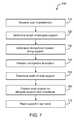
- FIG. 7shows a method 700 of fitting and placing components of a hearing aid for an ear of a user, according to embodiments of the present invention.
- a step 710measures a user characteristic correlated with a distance from the opening of an ear canal to the tympanic membrane, for example the actual distance from the ear canal opening to the tympanic membrane.
- a step 720determines a length of an elongate support from the measured characteristic to position a transducer near the tympanic membrane while the support is placed in the ear. In some embodiments, the determined length of the elongate support positions the transducer from about 2 to 6 mm from the tympanic membrane.
- the length of the elongate supportcan be determined to avoid contact with the ear between the microphone and the transducer.
- the length of the elongate supportcorresponds to the distance from the driver unit to the transducer, and additional patient characteristics can be measured, for example the length from the ear canal opening to the portion of the ear where the ear hook is placed.
- the distance of the elongate supportcorresponds to a distance from the ear canal opening to the proximal end of the coil assembly.
- a step 730determines a location of the microphone along the elongate support to place the microphone near the ear canal opening, for example within about 6 mm of the ear canal opening, while the transducer is placed near the tympanic membrane.
- a step 740positions the microphone at the location on the support.
- the microphonecan be positioned at the location in response to the length of the elongate support, for example the length determined by step 720 .
- a step 750determines a width of a positioner for placement in the ear canal near the transducer, for example a width sized to contact the skin of the ear canal to support the transducer and avoid contact between the transducer and the ear.
- a step 760positions the positioner on the elongate support near the transducer, for example the coil assembly.
- a step 770places the elongate support, transducer and microphone in the ear canal.
- FIG. 7provides a particular method of fitting and placing components of a hearing aid for an ear of a user, according to an embodiment of the present invention.
- Other sequences of stepsmay also be performed according to alternative embodiments.
- alternative embodiments of the present inventionmay perform the steps outlined above in a different order.
- the individual steps illustrated in FIG. 7may include multiple sub-steps that may be performed in various sequences as appropriate to the individual step.
- additional stepsmay be added or removed depending on the particular applications.
- One of ordinary skill in the artwould recognize many variations, modifications, and alternatives.
- FIG. 8Ashows an elongate support with a pair of positioners adapted to contact the ear canal and support the transducer, according to embodiments of the present invention.
- An elongate support 810extends to a coil assembly 819 .
- Coil assembly 819comprises a coil 816 , a core 817 and a biocompatible material 818 .
- Elongate support 810includes a wire 812 and a wire 814 electrically connected to coil 816 .
- Coil 816can include any of the coil configurations as described above.
- Wire 812 and wire 814are shown as a twisted pair, although other configurations can be used as described above.
- Elongate support 810comprises biocompatible material 818 formed over wire 812 and wire 814 . Biocompatible material 818 covers coil 816 and core 817 as described above.
- Wire 812 and wire 814are resilient members and are sized and comprise material selected to elastically flex in response to small deflections and provide support to coil assembly 819 .
- Wire 812 and wire 814are also sized and comprise material selected to deform in response to large deflections so that elongate support 810 can be deformed to a desired shape that matches the ear canal.
- Wire 812 and wire 814comprise metal and are adapted conduct heat from coil assembly 819 .
- Wire 812 and wire 814are soldered to coil 816 and can comprise a different gauge of wire from the wire of the coil, in particular a gauge with a range from about 26 to about 36 that is smaller than the gauge of the coil to provide resilient support and heat conduction.
- Additional heat conducting materialscan be used to conduct and transport heat from coil assembly 819 , for example shielding positioned around wire 812 and wire 814 .
- Elongate support 810 and wire 812 and wire 814extend toward the driver unit and are adapted to conduct heat out of the ear canal.
- FIG. 8Bshows an elongate support as in FIG. 8A attached to two positioners placed in an ear canal, according to embodiments of the present invention.
- a first positioner 830is attached to elongate support 810 near coil assembly 819 .
- First positioner 830engages the skin of the ear canal to support coil assembly 819 and avoid skin contact with the coil assembly.
- a second positioner 840is attached to elongate support 810 near ear canal opening 17 .
- Second positioner 840is sized to contact the skin of the ear canal near opening 17 to support elongate support 810 .
- a microphone 820is attached to elongate support 810 near ear canal opening 17 to detect high frequency sound localization cues.
- the positioners and elongate supportare sized and shaped so that the supports substantially avoid contact with the ear between the microphone and the coil assembly.
- a twisted pair of wires 822extends from microphone 820 to the driver unit and transmits an electronic auditory signal to the driver unit.
- microphone 820is shown lateral to positioner 840
- microphone 840can be positioned medial to positioner 840 .
- Elongate support 810is resilient and deformable as described above. Although elongate support 810 , positioner 830 and positioner 840 are shown as separate structures, the support can be formed from a single piece of material, for example a single piece of material formed with a mold.
- elongate support 81 , positioner 830 and positioner 840are each formed as separate pieces and assembled.
- the positionerscan be formed with holes adapted to receive the elongate support so that the positioners can be slid into position on the elongate support.
- FIG. 8Cshows a positioner adapted for placement near the opening to the ear canal according to embodiments of the present invention.
- Positioner 840includes flanges 842 that extend radially outward to engage the skin of the ear canal.
- Flanges 842are formed from a flexible material.
- Openings 844are defined by flanges 842 . Openings 844 permit sound waves to pass positioner 840 while the positioner is positioned in the ear canal, so that the sound waves are transmitted to the tympanic membrane.
- flanges 842define an outer boundary of support 840 with an elliptical shape
- flanges 842can comprise an outer boundary with any shape, for example circular.
- the positionerhas an outer boundary defined by the shape of the individual user's ear canal, for example embodiments where positioner 840 is made from a mold of the user's ear.
- Elongate support 810extends transversely through positioner 840 .
- FIG. 8Dshows a positioner adapted for placement near the coil assembly, according to embodiments of the present invention.
- Positioner 830includes flanges 832 that extend radially outward to engage the skin of the ear canal.
- Flanges 832are formed from a flexible material.
- Openings 834are defined by flanges 832 . Openings 834 permit sound waves to pass positioner 830 while the positioner is positioned in the ear canal, so that the sound waves are transmitted to the tympanic membrane.
- flanges 832define an outer boundary of support 830 with an elliptical shape, flanges 832 can comprise an outer boundary with any shape, for example circular.
- the positionerhas an outer boundary defined by the shape of the individual user's ear canal, for example embodiments where positioner 830 is made from a mold of the user's ear.
- Elongate support 810extends transversely through positioner 830 .
- an electromagnetic transducercomprising coil 819 is shown positioned on the end of elongate support 810
- the positioner and elongate supportcan be used with many types of transducers positioned at many locations, for example optical electromagnetic transducers positioned outside the ear canal and coupled to the support to deliver optical energy along the support, for example through at least one optical fiber.
- the at least one optical fibermay comprise a single optical fiber or a plurality of two or more optical fibers of the support.
- the plurality of optical fibersmay comprise a parallel configuration of optical fibers configured to transmit at least two channels in parallel along the support toward the eardrum of the user.
- FIG. 8B-1shows an elongate support configured to position a distal end of the elongate support with at least one positioners placed in an ear canal.
- Elongate support 810 and at least one positionerare configured to position support 810 in the ear canal with the electromagnetic energy transducer positioned outside the ear canal, and the microphone positioned at least one of in the ear canal or near the ear canal opening so as to detect high frequency spatial localization clues, as described above.
- the output energy transducer, or emittermay comprise a light source configured to emit electromagnetic energy comprising optical frequencies, and the light source can be positioned outside the ear canal, for example in a BTE unit.
- the light sourcemay comprise at least one of an LED or a laser diode, for example.
- the light sourcealso referred to as an emitter, can emit visible light, or infrared light, or a combination thereof.
- the light sourcecan be coupled to the distal end of the support with a waveguide, such as an optical fiber with a distal end of the optical fiber 810 D comprising a distal end of the support.
- the optical energy delivery transducercan be coupled to the proximal portion of the elongate support to transmit optical energy to the distal end.
- the positionercan be adapted to position the distal end of the support near an eardrum when the proximal portion is placed at a location near an ear canal opening.
- the intermediate portion of elongate support 810can be sized to minimize contact with a canal of the ear between the proximal portion to the distal end.
- the at least one positionercan improve optical coupling between the light source and a device positioned on the eardrum, so as to increase the efficiency of light energy transfer from the output energy transducer, or emitter, to an optical device positioned on the eardrum. For example, by improving alignment of the distal end 810 D of the support that emits light and a transducer positioned at least one of on the eardrum or in the middle ear.
- the at least one positioner and elongate support 810 comprising an optical fibercan be combined with many known optical transducer and hearing devices, for example as described in U.S. application Ser. No.
- elongate support 810may comprise an optical fiber coupled to positioner 830 to align the distal end of the optical fiber with an output transducer assembly supported on the eardrum.
- the output transducer assemblymay comprise a photodiode configured to receive light transmitted from the distal end of support 810 and supported with support component 30 placed on the eardrum, as described above.
- the output transducer assemblycan be separated from the distal end of the optical fiber, and the proximal end of the optical fiber can be positioned in the BTE unit and coupled to the light source.
- the output transducer assemblycan be similar to the output transducer assembly described in U.S. 2006/0189841, with positioner 830 used to align the optical fiber with the output transducer assembly, and the BTE unit may comprise a housing with the light source positioned therein.
- FIGS. 9A , 9 B and 9 Cshow a hearing aid device assembly with modular inter-connectable components to customize the device to the dimensions of the user, according to embodiments of the present invention.
- An assembly 900 of the hearing aid componentsincludes a BTE component 910 , an elongate canal component 920 and an elongate pinna component 930 .
- BTE component 910includes a processor, batteries and additional electronics as described above.
- a pinna dimension 902can be determined such that elongate pinna component 930 corresponds to pinna dimension 902 .
- pinna dimension 902corresponds to a distance from BTE component 910 to the ear canal opening.
- An ear canal length 904corresponds to a distance from the ear canal opening to the eardrum.
- a connector 928connects elongate pinna component 930 to elongate ear canal component 920 .
- Elongate canal component 920includes structure to provide patient comfort.
- a length 922 of elongate canal component 920can be selected so as to correspond to the ear canal of the patient.
- a coil assembly 924can be positioned near the ear canal and is covered with a biocompatible material as described above.
- Connector 928is sized to mate the connector on elongate pinna component 930 , such that several components can be combined for custom fit to the user.
- Elongate ear canal component 920includes a flexible portion 926 disposed between coil assembly 924 and connector 928 such that the elongate ear canal component 920 can flex and bend in response to user movement as described above.
- Flexible portion 926includes an inner section that has a hollow conic form to permit movement of the flexible portion.
- Elongate pinna component 930includes several structures to provide patient comfort.
- a length 932 of elongate pinna component 930can be selected so as to correspond to the pinna dimension, for example from the BTE unit to the ear opening.
- a microphone 934is sized to fit near the ear canal opening, in many embodiments within about 6 mm of the ear canal opening and without contacting the ear of the user.
- a connector 937is sized and shaped to mate with connector 928 of the ear canal component such that the combined components have a size customized for the user.
- Wires 936in many embodiments 5 wires, extend along the elongate pinna component to send signals from the microphone to the BTE unit and power the coil assembly with processed audio signals.
- elongate pinna component 930comprises an elongate plastic tube disposed over the wires to protect the wires and support the canal component. As least some of wires 936 may be sized to support the canal component and microphone. A connector 938 connects elongate pinna component 930 with BTE unit 910 .
- FIG. 9Dshows a partial cut away view of a hearing aid device assembly 900 D with a microphone 934 D and a transducer, for example a coil assembly 924 D, positioned inside a flexible support.
- Device assembly 900 Dmay comprise components of a system that includes a BTE unit and a magnet positioned on the ear, as described above.
- the flexible supportcomprises a flexible elongate pinna component 930 and a flexible elongate ear canal component 920 D.
- Flexible elongate ear canal component 920 Dcomprises a flexible sleeve 990 D, for example a flexible tube, that defines an enclosure 991 D, for example a lumen of the tube.
- Microphone 934 D and coil assembly 924 Dmay be positioned within enclosure 991 D defined by flexible sleeve 990 D. Microphone 934 D and coil assembly 924 D can be sized to fit inside enclosure 991 D of sleeve 990 D and sized to minimize contact with the ear inside the canal.
- Can assembly 924 Dmay comprise many of the coil assemblies described above, for example coil assemblies adapted to couple to a magnet positioned on the eardrum.
- Microphone 934 Dcan be positioned lateral to coil assembly 924 D along an elongate axis 999 D of flexible sleeve 990 D.
- Flexible sleeve 990 Dmay comprise at least one opening, for example multiple openings 994 D, for conduction of sound from the ear canal to microphone 934 D.
- Elongate flexible sleeve 990 Dcan extend from a proximal connector 928 D to a distal end 997 D, and may be sized in cross section so as to minimize contact with the ear canal.
- at least an intermediate portion of sleeve 990 D between connector 928 D and distal end 997 Dis sized to minimize contact with the ear canal, for example the portion over microphone 934 D.
- Flexible elongate ear canal component 920 Dincludes structures for patient comfort.
- flexible elongate ear canal component 920 Dcan include structures, such that the elongate ear canal component 920 D can flex and/or bend in response to user movement.
- a flexible portion 993 D of sleeve 990 Dis disposed between coil assembly 924 D and connector 928 D.
- Flexible portion 993 Dcan include a hollow section of enclosure 991 D to permit movement of the flexible portion and elongate canal component 920 D in response to patient facial movements including opening and closing of the jaw so as to provide patient comfort.
- Wires 936 D that connect the BTE unit to the coil assembly and/or microphonecan also flex at least along the flexible portion of the elongate canal component.
- End 997 D of flexible sleeve 990 Dcan be rounded, such the rounded end 997 D can slide along the ear canal when the rounded end contacts the ear inside the canal. Flexure of the elongate canal component, for example with bending of the flexible portion, can also minimize patient discomfort when the rounded end contacts the ear canal and/or slides along the ear canal.
- microphone 934can be positioned between the coil assembly 924 D and the connector 928 D to measure sound near the eardrum.
- a microphone portfor example opening 935 D, faces the coil assembly 924 D.
- An air gap 992 Dcan be provided in a hollow section of enclosure 991 D between the coil assembly 924 D and microphone opening 935 D.
- Microphone opening 935 Dis in acoustic communication with the ear canal so as to receive sound from the ear canal through at least one opening, for example several openings 994 D, in sleeve 990 D.
- Air gap 992 Dmay extend a distance 996 D of no more than about 12 mm, for example no more than about 6 mm, such that opening 935 D and openings 994 D are positioned deep in the ear canal so as to receive sound similar to that received by the eardrum.
- This placement of the microphone and openings near the eardrumcan avoid having to measure the gain of sound transfer from the ear canal opening to the eardrum, and thus may avoid having to compensate for this transfer function, which can have practical advantages.
- microphone opening 935 D and air gap 992 Dare protected from invasion by ear canal wax and corrosive substances with known “cerumen guard” methods and/or substances applied to the several port openings 994 D.
- Hearing aid device assembly 900 Dcan include modular inter-connectable components to customize the device to the dimensions of the user, according to embodiments of the present invention.
- Assembly 900 D of the hearing aid componentsincludes a BTE component 910 D, elongate canal component 920 D and an elongate pinna component 930 D.
- BTE component 910 Dincludes a processor, batteries and additional electronics as described above.
- a pinna dimension 902 Dcan be determined such that elongate pinna component 930 D corresponds to pinna dimension 902 D.
- pinna dimension 902 Dcorresponds to a distance from BTE component 910 D to the ear canal opening.
- An ear canal length 904 Dcorresponds to a distance from the ear canal opening to the eardrum, as described above.
- a connector 928 Dconnects elongate pinna component 930 D to elongate ear canal component 920 D.
- a length 922 D of elongate canal component 920 Dcan be selected so as to correspond to the ear canal of the patient, as described above.
- a coil assembly 924 Dcan be positioned inside the ear canal and is covered with a biocompatible material, as described above.
- Connector 928 Dis sized to mate connector 937 D on elongate pinna component 930 , such that several components can be combined for custom fit to the user, as described above.
- Elongate pinna component 930 Dincludes several structures to provide patient comfort similar to those described above.
- a length 932 D of elongate pinna component 930 Dcan be selected so as to correspond to the pinna dimension, for example from the BTE unit to the ear opening.
- a connector 937 Dis sized and shaped to mate with connector 928 D of the ear canal component such that the combined components have a size customized for the user.
- Wires 936 Din many embodiments 5 wires, extend along the elongate pinna component to send signals from the microphone to the BTE unit and power the coil assembly with processed audio signals.
- elongate pinna component 930 Dcomprises an elongate plastic tube disposed over the wires to protect the wires and support the canal component. As least some of wires 936 D may be sized and/or coiled to flex with the canal component and microphone.
- a connector 938 Dconnects elongate pinna component 930 D with BTE unit 910 D.
- FIG. 9Eshows a hearing aid device assembly 950 with a tube 982 along the elongate pinna component to conduct sound from the ear canal opening to a microphone positioned away from the ear canal opening, according to embodiments of the present invention.
- assembly 950includes elongate ear canal component 920 as described above.
- An opening 982 Ais formed near the end of tube 982 to detect sound near the opening to the ear canal, in many embodiments within about 6 mm of the opening of the ear canal. Sound is conducted along tube 982 from opening 982 A toward a microphone 984 near an opposing end of pinna component 980 .
- Pinna component 980includes a connector 988 to connect to a BTE unit 960 .
- BTE unit 960includes a connector 967 that mates with connector 988 .
- microphone 984may be located in BTE unit 960 and connector 967 and connector 968 may conduct sound to the microphone located in the BTE unit.
- the elongate ear canal component and elongate pinna componentcan be selected to match dimensions of the user.
- Elongate pinna component 930 and elongate ear canal component 920may comprise optical waveguides, for example optical fibers, to transmit light to a transducer positioned on the eardrum, as described above.
- the light sourcemay be positioned on the BTE component, and each of the elongate pinna component and the elongate ear canal component may comprise an optical fiber and an optical coupling to couple light from the BTE component to the distal end of the elongate support.
- FIG. 10shows a method 1000 of selecting components to fit a user with components as in FIGS. 9A to 9E , according to embodiments of the present invention.
- a user pinna characteristicis determined.
- the determined pinna characteristiccorresponds to the actual distance measured from the location of the BTE connector to the opening of the ear canal, although the pinna characteristic can be determined in other ways, for example the cross sectional size of the pinna from top to bottom.
- a pinna componentis selected based on the determined pinna characteristic, for example, one of three available lengths of pinna components can be selected for the user.
- a user ear canal componentis determined.
- the determined ear canal characteristiccorresponds to the actual measured length of the ear canal, although the ear canal characteristic can be determined in other ways.
- the ear canal characteristiccan correspond to the width of the user's head or other anatomy correlated with the user's ear canal length.
- an ear canal componentis selected based on the determined ear canal characteristic.
- one ear canal componentis selected from among three available sizes of ear canal components.
- the number of configurations of assembled devicescorresponds to the product of available pinna sizes and available ear canal sizes. For example, with three sizes of pinna components available and three sizes of ear canal components available, nine configurations of the device assembly are available to the user.
- the componentsare combined.
- the componentsare placed in the user's ear.
- FIG. 10provides a particular method of fitting a hearing aid device according to an embodiment of the present invention.
- Other sequences of stepsmay also be performed according to alternative embodiments.
- alternative embodiments of the present inventionmay perform the steps outlined above in a different order.
- the individual steps illustrated in FIG. 10may include multiple sub-steps that may be performed in various sequences as appropriate to the individual step.
- additional stepsmay be added or removed depending on the particular applications.
- One of ordinary skill in the artwould recognize many variations, modifications, and alternatives.
Landscapes
- Engineering & Computer Science (AREA)
- Health & Medical Sciences (AREA)
- General Health & Medical Sciences (AREA)
- Neurosurgery (AREA)
- Otolaryngology (AREA)
- Physics & Mathematics (AREA)
- Acoustics & Sound (AREA)
- Signal Processing (AREA)
- Manufacturing & Machinery (AREA)
- Headphones And Earphones (AREA)
Abstract
Description
Claims (23)
Priority Applications (3)
| Application Number | Priority Date | Filing Date | Title |
|---|---|---|---|
| US12/244,266US8295523B2 (en) | 2007-10-04 | 2008-10-02 | Energy delivery and microphone placement methods for improved comfort in an open canal hearing aid |
| US13/768,825US9226083B2 (en) | 2004-07-28 | 2013-02-15 | Multifunction system and method for integrated hearing and communication with noise cancellation and feedback management |
| US14/949,495US20160277854A1 (en) | 2004-07-28 | 2015-11-23 | Multifunction System and Method for Integrated Hearing and Communication with Noise Cancellation and Feedback Management |
Applications Claiming Priority (2)
| Application Number | Priority Date | Filing Date | Title |
|---|---|---|---|
| US97760507P | 2007-10-04 | 2007-10-04 | |
| US12/244,266US8295523B2 (en) | 2007-10-04 | 2008-10-02 | Energy delivery and microphone placement methods for improved comfort in an open canal hearing aid |
Publications (2)
| Publication Number | Publication Date |
|---|---|
| US20090092271A1 US20090092271A1 (en) | 2009-04-09 |
| US8295523B2true US8295523B2 (en) | 2012-10-23 |
Family
ID=40523264
Family Applications (1)
| Application Number | Title | Priority Date | Filing Date |
|---|---|---|---|
| US12/244,266Active2031-04-07US8295523B2 (en) | 2004-07-28 | 2008-10-02 | Energy delivery and microphone placement methods for improved comfort in an open canal hearing aid |
Country Status (3)
| Country | Link |
|---|---|
| US (1) | US8295523B2 (en) |
| EP (1) | EP2206360A4 (en) |
| WO (1) | WO2009046329A1 (en) |
Cited By (27)
| Publication number | Priority date | Publication date | Assignee | Title |
|---|---|---|---|---|
| US20100296664A1 (en)* | 2009-02-23 | 2010-11-25 | Verto Medical Solutions Llc | Earpiece system |
| US20130182882A1 (en)* | 2008-07-24 | 2013-07-18 | Massachusetts Institute Of Technology | Positioning an input transducer for an earpiece based upon dynamic data |
| US20140050489A1 (en)* | 2011-08-25 | 2014-02-20 | Panasonic Corporation | Optical microphone |
| US8824715B2 (en) | 2008-06-17 | 2014-09-02 | Earlens Corporation | Optical electro-mechanical hearing devices with combined power and signal architectures |
| US20150264496A1 (en)* | 2014-03-13 | 2015-09-17 | Bernafon Ag | Method for producing hearing aid fittings |
| US9226083B2 (en) | 2004-07-28 | 2015-12-29 | Earlens Corporation | Multifunction system and method for integrated hearing and communication with noise cancellation and feedback management |
| US9392377B2 (en) | 2010-12-20 | 2016-07-12 | Earlens Corporation | Anatomically customized ear canal hearing apparatus |
| US20160331965A1 (en)* | 2015-05-14 | 2016-11-17 | Kuang-Chao Chen | Cochlea hearing aid fixed on eardrum |
| US9544675B2 (en) | 2014-02-21 | 2017-01-10 | Earlens Corporation | Contact hearing system with wearable communication apparatus |
| US9591409B2 (en) | 2008-06-17 | 2017-03-07 | Earlens Corporation | Optical electro-mechanical hearing devices with separate power and signal components |
| US20170095202A1 (en)* | 2015-10-02 | 2017-04-06 | Earlens Corporation | Drug delivery customized ear canal apparatus |
| US9749758B2 (en) | 2008-09-22 | 2017-08-29 | Earlens Corporation | Devices and methods for hearing |
| US20170325036A1 (en)* | 2014-10-09 | 2017-11-09 | Sonova Ag | Hearing device |
| US9924276B2 (en) | 2014-11-26 | 2018-03-20 | Earlens Corporation | Adjustable venting for hearing instruments |
| US9930458B2 (en) | 2014-07-14 | 2018-03-27 | Earlens Corporation | Sliding bias and peak limiting for optical hearing devices |
| US9949039B2 (en) | 2005-05-03 | 2018-04-17 | Earlens Corporation | Hearing system having improved high frequency response |
| US10034103B2 (en) | 2014-03-18 | 2018-07-24 | Earlens Corporation | High fidelity and reduced feedback contact hearing apparatus and methods |
| US10178483B2 (en) | 2015-12-30 | 2019-01-08 | Earlens Corporation | Light based hearing systems, apparatus, and methods |
| US10492010B2 (en) | 2015-12-30 | 2019-11-26 | Earlens Corporations | Damping in contact hearing systems |
| US11102594B2 (en) | 2016-09-09 | 2021-08-24 | Earlens Corporation | Contact hearing systems, apparatus and methods |
| US11166114B2 (en) | 2016-11-15 | 2021-11-02 | Earlens Corporation | Impression procedure |
| US11212626B2 (en) | 2018-04-09 | 2021-12-28 | Earlens Corporation | Dynamic filter |
| US11343617B2 (en) | 2018-07-31 | 2022-05-24 | Earlens Corporation | Modulation in a contact hearing system |
| US11350226B2 (en) | 2015-12-30 | 2022-05-31 | Earlens Corporation | Charging protocol for rechargeable hearing systems |
| US11516603B2 (en) | 2018-03-07 | 2022-11-29 | Earlens Corporation | Contact hearing device and retention structure materials |
| US11930325B2 (en) | 2019-03-27 | 2024-03-12 | Earlens Corporation | Direct print chassis for contact hearing system |
| US20240314506A1 (en)* | 2018-12-04 | 2024-09-19 | Oticon A/S | Speaker assembly for hearing aid |
Families Citing this family (25)
| Publication number | Priority date | Publication date | Assignee | Title |
|---|---|---|---|---|
| US7867160B2 (en)* | 2004-10-12 | 2011-01-11 | Earlens Corporation | Systems and methods for photo-mechanical hearing transduction |
| US8396239B2 (en) | 2008-06-17 | 2013-03-12 | Earlens Corporation | Optical electro-mechanical hearing devices with combined power and signal architectures |
| CN104320748B (en)* | 2008-12-10 | 2017-10-24 | Med-El电气医疗器械有限公司 | Skull vibrational unit |
| DE102009016843B3 (en)* | 2009-04-08 | 2010-08-05 | Siemens Medical Instruments Pte. Ltd. | Magnetofluidic hearing aid system |
| EP2438768B1 (en) | 2009-06-05 | 2016-03-16 | Earlens Corporation | Optically coupled acoustic middle ear implant device |
| US9544700B2 (en)* | 2009-06-15 | 2017-01-10 | Earlens Corporation | Optically coupled active ossicular replacement prosthesis |
| JP2012530552A (en)* | 2009-06-18 | 2012-12-06 | サウンドビーム エルエルシー | Optically coupled cochlear implant system and method |
| CN102598713A (en)* | 2009-06-18 | 2012-07-18 | 音束有限责任公司 | Eardrum implantable devices for hearing systems and methods |
| US10555100B2 (en) | 2009-06-22 | 2020-02-04 | Earlens Corporation | Round window coupled hearing systems and methods |
| EP2446645B1 (en) | 2009-06-22 | 2020-05-06 | Earlens Corporation | Optically coupled bone conduction systems and methods |
| US8715154B2 (en)* | 2009-06-24 | 2014-05-06 | Earlens Corporation | Optically coupled cochlear actuator systems and methods |
| WO2010151636A2 (en) | 2009-06-24 | 2010-12-29 | SoundBeam LLC | Optical cochlear stimulation devices and methods |
| US8061473B1 (en)* | 2010-08-10 | 2011-11-22 | Simply Sound | Passive personal vocal monitor |
| DE102010040777A1 (en)* | 2010-09-15 | 2012-03-15 | Robert Bosch Gmbh | Ear thermometer and method for measuring body temperature |
| KR101223693B1 (en) | 2011-06-16 | 2013-01-21 | 경북대학교 산학협력단 | Round window driving vibrator of three-coils type with excellent driving force |
| NL2007136C2 (en)* | 2011-07-18 | 2013-01-21 | Exsilent Res Bv | LISTENING SUPPORT DEVICE, IN PARTICULAR A HEARING DEVICE, AND A COMPRESSIBLE HOSE FOR USE THEREOF. |
| US20130116497A1 (en)* | 2011-11-08 | 2013-05-09 | Cochlear Limited | Coupling Systems For Implantable Prosthesis Components |
| EP2608576B1 (en)* | 2011-12-21 | 2020-02-26 | Sonion Nederland B.V. | An apparatus and a method for providing sound |
| US11534608B2 (en) | 2015-01-04 | 2022-12-27 | Ist, Llc | Methods and apparatuses for transdermal stimulation of the outer ear |
| TWI577193B (en)* | 2015-03-19 | 2017-04-01 | 陳光超 | Hearing-aid on eardrum |
| WO2017183003A1 (en)* | 2016-04-22 | 2017-10-26 | Cochlear Limited | Microphone placement |
| EP3335625B1 (en)* | 2016-12-14 | 2024-10-16 | Interacoustics A/S | Ear probe for hearing testing |
| CN111787977B (en) | 2018-02-27 | 2024-09-27 | 领先仿生公司 | Sound transmission equipment for audiometric measurements |
| WO2020150737A1 (en)* | 2019-01-18 | 2020-07-23 | Ist, Llc | Methods and devices for modulation of integrated neural networks to influence composite sensory processes |
| WO2021211318A1 (en)* | 2020-04-13 | 2021-10-21 | Earlens Corporation | Unibody floating magnet contact hearing system |
Citations (209)
| Publication number | Priority date | Publication date | Assignee | Title |
|---|---|---|---|---|
| US3440314A (en) | 1966-09-30 | 1969-04-22 | Dow Corning | Method of making custom-fitted earplugs for hearing aids |
| US3549818A (en) | 1967-08-15 | 1970-12-22 | Message Systems Inc | Transmitting antenna for audio induction communication system |
| US3585416A (en) | 1969-10-07 | 1971-06-15 | Howard G Mellen | Photopiezoelectric transducer |
| US3594514A (en) | 1970-01-02 | 1971-07-20 | Medtronic Inc | Hearing aid with piezoelectric ceramic element |
| US3710399A (en) | 1970-06-23 | 1973-01-16 | H Hurst | Ossicle replacement prosthesis |
| US3712962A (en) | 1971-04-05 | 1973-01-23 | J Epley | Implantable piezoelectric hearing aid |
| US3764748A (en) | 1972-05-19 | 1973-10-09 | J Branch | Implanted hearing aids |
| US3808179A (en) | 1972-06-16 | 1974-04-30 | Polycon Laboratories | Oxygen-permeable contact lens composition,methods and article of manufacture |
| US3882285A (en) | 1973-10-09 | 1975-05-06 | Vicon Instr Company | Implantable hearing aid and method of improving hearing |
| US3985977A (en) | 1975-04-21 | 1976-10-12 | Motorola, Inc. | Receiver system for receiving audio electrical signals |
| US4002897A (en) | 1975-09-12 | 1977-01-11 | Bell Telephone Laboratories, Incorporated | Opto-acoustic telephone receiver |
| US4061972A (en) | 1973-12-03 | 1977-12-06 | Victor Robert Burgess | Short range induction field communication system |
| US4075042A (en) | 1973-11-16 | 1978-02-21 | Raytheon Company | Samarium-cobalt magnet with grain growth inhibited SmCo5 crystals |
| US4098277A (en) | 1977-01-28 | 1978-07-04 | Sherwin Mendell | Fitted, integrally molded device for stimulating auricular acupuncture points and method of making the device |
| US4120570A (en) | 1976-06-22 | 1978-10-17 | Syntex (U.S.A.) Inc. | Method for correcting visual defects, compositions and articles of manufacture useful therein |
| DE2044870C3 (en) | 1970-09-10 | 1978-12-21 | Dietrich Prof. Dr.Med. 7400 Tuebingen Plester | Hearing aid arrangement for the inductive transmission of acoustic signals |
| US4248899A (en) | 1979-02-26 | 1981-02-03 | The United States Of America As Represented By The Secretary Of Agriculture | Protected feeds for ruminants |
| US4252440A (en) | 1978-12-15 | 1981-02-24 | Nasa | Photomechanical transducer |
| US4303772A (en) | 1979-09-04 | 1981-12-01 | George F. Tsuetaki | Oxygen permeable hard and semi-hard contact lens compositions methods and articles of manufacture |
| US4319359A (en) | 1980-04-10 | 1982-03-09 | Rca Corporation | Radio transmitter energy recovery system |
| US4334315A (en) | 1979-05-04 | 1982-06-08 | Gen Engineering, Ltd. | Wireless transmitting and receiving systems including ear microphones |
| US4334321A (en) | 1981-01-19 | 1982-06-08 | Seymour Edelman | Opto-acoustic transducer and telephone receiver |
| US4357497A (en) | 1979-09-24 | 1982-11-02 | Hochmair Ingeborg | System for enhancing auditory stimulation and the like |
| US4380689A (en) | 1979-08-01 | 1983-04-19 | Vittorio Giannetti | Electroacoustic transducer for hearing aids |
| US4428377A (en) | 1980-03-06 | 1984-01-31 | Siemens Aktiengesellschaft | Method for the electrical stimulation of the auditory nerve and multichannel hearing prosthesis for carrying out the method |
| DE3243850A1 (en) | 1982-11-26 | 1984-05-30 | Manfred 6231 Sulzbach Koch | Induction coil for hearing aids for those with impaired hearing, for the reception of low-frequency electrical signals |
| US4524294A (en) | 1984-05-07 | 1985-06-18 | The United States Of America As Represented By The Secretary Of The Army | Ferroelectric photomechanical actuators |
| US4540761A (en) | 1982-07-27 | 1985-09-10 | Hoya Lens Corporation | Oxygen-permeable hard contact lens |
| US4556122A (en) | 1981-08-31 | 1985-12-03 | Innovative Hearing Corporation | Ear acoustical hearing aid |
| US4592087A (en) | 1983-12-08 | 1986-05-27 | Industrial Research Products, Inc. | Class D hearing aid amplifier |
| US4606329A (en) | 1985-05-22 | 1986-08-19 | Xomed, Inc. | Implantable electromagnetic middle-ear bone-conduction hearing aid device |
| US4611598A (en) | 1984-05-30 | 1986-09-16 | Hortmann Gmbh | Multi-frequency transmission system for implanted hearing aids |
| US4628907A (en) | 1984-03-22 | 1986-12-16 | Epley John M | Direct contact hearing aid apparatus |
| US4641377A (en) | 1984-04-06 | 1987-02-03 | Institute Of Gas Technology | Photoacoustic speaker and method |
| US4689819A (en) | 1983-12-08 | 1987-08-25 | Industrial Research Products, Inc. | Class D hearing aid amplifier |
| US4696287A (en) | 1985-02-26 | 1987-09-29 | Hortmann Gmbh | Transmission system for implanted hearing aids |
| US4729366A (en) | 1984-12-04 | 1988-03-08 | Medical Devices Group, Inc. | Implantable hearing aid and method of improving hearing |
| US4741339A (en) | 1984-10-22 | 1988-05-03 | Cochlear Pty. Limited | Power transfer for implanted prostheses |
| US4742499A (en) | 1986-06-13 | 1988-05-03 | Image Acoustics, Inc. | Flextensional transducer |
| US4756312A (en) | 1984-03-22 | 1988-07-12 | Advanced Hearing Technology, Inc. | Magnetic attachment device for insertion and removal of hearing aid |
| US4766607A (en) | 1987-03-30 | 1988-08-23 | Feldman Nathan W | Method of improving the sensitivity of the earphone of an optical telephone and earphone so improved |
| US4774933A (en) | 1987-05-18 | 1988-10-04 | Xomed, Inc. | Method and apparatus for implanting hearing device |
| US4776322A (en) | 1985-05-22 | 1988-10-11 | Xomed, Inc. | Implantable electromagnetic middle-ear bone-conduction hearing aid device |
| EP0296092A2 (en) | 1987-06-19 | 1988-12-21 | George Geladakis | Arrangement for wireless earphones without batteries and electronic circuits, applicable in audio-systems or audio-visual systems of all kinds |
| US4800884A (en) | 1986-03-07 | 1989-01-31 | Richards Medical Company | Magnetic induction hearing aid |
| US4817607A (en) | 1986-03-07 | 1989-04-04 | Richards Medical Company | Magnetic ossicular replacement prosthesis |
| US4840178A (en) | 1986-03-07 | 1989-06-20 | Richards Metal Company | Magnet for installation in the middle ear |
| US4845755A (en) | 1984-08-28 | 1989-07-04 | Siemens Aktiengesellschaft | Remote control hearing aid |
| US4932405A (en) | 1986-08-08 | 1990-06-12 | Antwerp Bionic Systems N.V. | System of stimulating at least one nerve and/or muscle fibre |
| US4936305A (en) | 1988-07-20 | 1990-06-26 | Richards Medical Company | Shielded magnetic assembly for use with a hearing aid |
| US4944301A (en) | 1988-06-16 | 1990-07-31 | Cochlear Corporation | Method for determining absolute current density through an implanted electrode |
| US4948855A (en) | 1986-02-06 | 1990-08-14 | Progressive Chemical Research, Ltd. | Comfortable, oxygen permeable contact lenses and the manufacture thereof |
| US4957478A (en) | 1988-10-17 | 1990-09-18 | Maniglia Anthony J | Partially implantable hearing aid device |
| US4999819A (en) | 1990-04-18 | 1991-03-12 | The Pennsylvania Research Corporation | Transformed stress direction acoustic transducer |
| US5003608A (en) | 1989-09-22 | 1991-03-26 | Resound Corporation | Apparatus and method for manipulating devices in orifices |
| US5012520A (en) | 1988-05-06 | 1991-04-30 | Siemens Aktiengesellschaft | Hearing aid with wireless remote control |
| US5015224A (en) | 1988-10-17 | 1991-05-14 | Maniglia Anthony J | Partially implantable hearing aid device |
| US5015225A (en) | 1985-05-22 | 1991-05-14 | Xomed, Inc. | Implantable electromagnetic middle-ear bone-conduction hearing aid device |
| US5031219A (en) | 1988-09-15 | 1991-07-09 | Epic Corporation | Apparatus and method for conveying amplified sound to the ear |
| US5061282A (en) | 1989-10-10 | 1991-10-29 | Jacobs Jared J | Cochlear implant auditory prosthesis |
| US5066091A (en) | 1988-12-22 | 1991-11-19 | Kingston Technologies, Inc. | Amorphous memory polymer alignment device with access means |
| US5094108A (en) | 1990-09-28 | 1992-03-10 | Korea Standards Research Institute | Ultrasonic contact transducer for point-focussing surface waves |
| US5117461A (en) | 1989-08-10 | 1992-05-26 | Mnc, Inc. | Electroacoustic device for hearing needs including noise cancellation |
| US5142186A (en) | 1991-08-05 | 1992-08-25 | United States Of America As Represented By The Secretary Of The Air Force | Single crystal domain driven bender actuator |
| US5163957A (en) | 1991-09-10 | 1992-11-17 | Smith & Nephew Richards, Inc. | Ossicular prosthesis for mounting magnet |
| US5167235A (en) | 1991-03-04 | 1992-12-01 | Pat O. Daily Revocable Trust | Fiber optic ear thermometer |
| US5201007A (en) | 1988-09-15 | 1993-04-06 | Epic Corporation | Apparatus and method for conveying amplified sound to ear |
| US5259032A (en) | 1990-11-07 | 1993-11-02 | Resound Corporation | contact transducer assembly for hearing devices |
| US5272757A (en) | 1990-09-12 | 1993-12-21 | Sonics Associates, Inc. | Multi-dimensional reproduction system |
| US5276910A (en) | 1991-09-13 | 1994-01-04 | Resound Corporation | Energy recovering hearing system |
| US5277694A (en) | 1991-02-13 | 1994-01-11 | Implex Gmbh | Electromechanical transducer for implantable hearing aids |
| US5402496A (en) | 1992-07-13 | 1995-03-28 | Minnesota Mining And Manufacturing Company | Auditory prosthesis, noise suppression apparatus and feedback suppression apparatus having focused adaptive filtering |
| US5411467A (en) | 1989-06-02 | 1995-05-02 | Implex Gmbh Spezialhorgerate | Implantable hearing aid |
| US5425104A (en) | 1991-04-01 | 1995-06-13 | Resound Corporation | Inconspicuous communication method utilizing remote electromagnetic drive |
| US5440237A (en) | 1993-06-01 | 1995-08-08 | Incontrol Solutions, Inc. | Electronic force sensing with sensor normalization |
| US5440082A (en) | 1991-09-19 | 1995-08-08 | U.S. Philips Corporation | Method of manufacturing an in-the-ear hearing aid, auxiliary tool for use in the method, and ear mould and hearing aid manufactured in accordance with the method |
| US5455994A (en) | 1992-11-17 | 1995-10-10 | U.S. Philips Corporation | Method of manufacturing an in-the-ear hearing aid |
| US5456654A (en) | 1993-07-01 | 1995-10-10 | Ball; Geoffrey R. | Implantable magnetic hearing aid transducer |
| US5531954A (en) | 1994-08-05 | 1996-07-02 | Resound Corporation | Method for fabricating a hearing aid housing |
| US5531787A (en) | 1993-01-25 | 1996-07-02 | Lesinski; S. George | Implantable auditory system with micromachined microsensor and microactuator |
| US5554096A (en) | 1993-07-01 | 1996-09-10 | Symphonix | Implantable electromagnetic hearing transducer |
| US5558618A (en) | 1995-01-23 | 1996-09-24 | Maniglia; Anthony J. | Semi-implantable middle ear hearing device |
| US5606621A (en) | 1995-06-14 | 1997-02-25 | Siemens Hearing Instruments, Inc. | Hybrid behind-the-ear and completely-in-canal hearing aid |
| US5624376A (en) | 1993-07-01 | 1997-04-29 | Symphonix Devices, Inc. | Implantable and external hearing systems having a floating mass transducer |
| US5707338A (en) | 1996-08-07 | 1998-01-13 | St. Croix Medical, Inc. | Stapes vibrator |
| US5721783A (en) | 1995-06-07 | 1998-02-24 | Anderson; James C. | Hearing aid with wireless remote processor |
| US5729077A (en) | 1995-12-15 | 1998-03-17 | The Penn State Research Foundation | Metal-electroactive ceramic composite transducer |
| US5740258A (en) | 1995-06-05 | 1998-04-14 | Mcnc | Active noise supressors and methods for use in the ear canal |
| US5762583A (en) | 1996-08-07 | 1998-06-09 | St. Croix Medical, Inc. | Piezoelectric film transducer |
| US5772575A (en) | 1995-09-22 | 1998-06-30 | S. George Lesinski | Implantable hearing aid |
| US5774259A (en) | 1995-09-28 | 1998-06-30 | Kabushiki Kaisha Topcon | Photorestrictive device controller and control method therefor |
| US5782744A (en) | 1995-11-13 | 1998-07-21 | Money; David | Implantable microphone for cochlear implants and the like |
| US5788711A (en) | 1996-05-10 | 1998-08-04 | Implex Gmgh Spezialhorgerate | Implantable positioning and fixing system for actuator and sensor implants |
| US5795287A (en) | 1996-01-03 | 1998-08-18 | Symphonix Devices, Inc. | Tinnitus masker for direct drive hearing devices |
| US5797834A (en) | 1996-05-31 | 1998-08-25 | Resound Corporation | Hearing improvement device |
| US5800336A (en) | 1993-07-01 | 1998-09-01 | Symphonix Devices, Inc. | Advanced designs of floating mass transducers |
| US5804109A (en) | 1996-11-08 | 1998-09-08 | Resound Corporation | Method of producing an ear canal impression |
| US5804907A (en) | 1997-01-28 | 1998-09-08 | The Penn State Research Foundation | High strain actuator using ferroelectric single crystal |
| US5814095A (en) | 1996-09-18 | 1998-09-29 | Implex Gmbh Spezialhorgerate | Implantable microphone and implantable hearing aids utilizing same |
| US5825122A (en) | 1994-07-26 | 1998-10-20 | Givargizov; Evgeny Invievich | Field emission cathode and a device based thereon |
| US5836863A (en) | 1996-08-07 | 1998-11-17 | St. Croix Medical, Inc. | Hearing aid transducer support |
| US5842967A (en) | 1996-08-07 | 1998-12-01 | St. Croix Medical, Inc. | Contactless transducer stimulation and sensing of ossicular chain |
| US5859916A (en) | 1996-07-12 | 1999-01-12 | Symphonix Devices, Inc. | Two stage implantable microphone |
| US5879283A (en) | 1996-08-07 | 1999-03-09 | St. Croix Medical, Inc. | Implantable hearing system having multiple transducers |
| US5888187A (en) | 1997-03-27 | 1999-03-30 | Symphonix Devices, Inc. | Implantable microphone |
| US5897486A (en) | 1993-07-01 | 1999-04-27 | Symphonix Devices, Inc. | Dual coil floating mass transducers |
| US5899847A (en) | 1996-08-07 | 1999-05-04 | St. Croix Medical, Inc. | Implantable middle-ear hearing assist system using piezoelectric transducer film |
| US5900274A (en) | 1998-05-01 | 1999-05-04 | Eastman Kodak Company | Controlled composition and crystallographic changes in forming functionally gradient piezoelectric transducers |
| US5906635A (en) | 1995-01-23 | 1999-05-25 | Maniglia; Anthony J. | Electromagnetic implantable hearing device for improvement of partial and total sensoryneural hearing loss |
| US5913815A (en) | 1993-07-01 | 1999-06-22 | Symphonix Devices, Inc. | Bone conducting floating mass transducers |
| US5940519A (en) | 1996-12-17 | 1999-08-17 | Texas Instruments Incorporated | Active noise control system and method for on-line feedback path modeling and on-line secondary path modeling |
| US5949895A (en) | 1995-09-07 | 1999-09-07 | Symphonix Devices, Inc. | Disposable audio processor for use with implanted hearing devices |
| US5987146A (en) | 1997-04-03 | 1999-11-16 | Resound Corporation | Ear canal microphone |
| US6005955A (en) | 1996-08-07 | 1999-12-21 | St. Croix Medical, Inc. | Middle ear transducer |
| US6024717A (en) | 1996-10-24 | 2000-02-15 | Vibrx, Inc. | Apparatus and method for sonically enhanced drug delivery |
| US6045528A (en) | 1997-06-13 | 2000-04-04 | Intraear, Inc. | Inner ear fluid transfer and diagnostic system |
| US6068589A (en) | 1996-02-15 | 2000-05-30 | Neukermans; Armand P. | Biocompatible fully implantable hearing aid transducers |
| US6068590A (en) | 1997-10-24 | 2000-05-30 | Hearing Innovations, Inc. | Device for diagnosing and treating hearing disorders |
| US6084975A (en) | 1998-05-19 | 2000-07-04 | Resound Corporation | Promontory transmitting coil and tympanic membrane magnet for hearing devices |
| US6093144A (en) | 1997-12-16 | 2000-07-25 | Symphonix Devices, Inc. | Implantable microphone having improved sensitivity and frequency response |
| US6137889A (en) | 1998-05-27 | 2000-10-24 | Insonus Medical, Inc. | Direct tympanic membrane excitation via vibrationally conductive assembly |
| US6139488A (en) | 1997-09-25 | 2000-10-31 | Symphonix Devices, Inc. | Biasing device for implantable hearing devices |
| US6153966A (en) | 1996-07-19 | 2000-11-28 | Neukermans; Armand P. | Biocompatible, implantable hearing aid microactuator |
| US6181801B1 (en) | 1997-04-03 | 2001-01-30 | Resound Corporation | Wired open ear canal earpiece |
| US6190306B1 (en) | 1997-08-07 | 2001-02-20 | St. Croix Medical, Inc. | Capacitive input transducer for middle ear sensing |
| US6208445B1 (en) | 1996-12-20 | 2001-03-27 | Nokia Gmbh | Apparatus for wireless optical transmission of video and/or audio information |
| US6217508B1 (en) | 1998-08-14 | 2001-04-17 | Symphonix Devices, Inc. | Ultrasonic hearing system |
| US6222927B1 (en) | 1996-06-19 | 2001-04-24 | The University Of Illinois | Binaural signal processing system and method |
| US6222302B1 (en) | 1997-09-30 | 2001-04-24 | Matsushita Electric Industrial Co., Ltd. | Piezoelectric actuator, infrared sensor and piezoelectric light deflector |
| US6240192B1 (en) | 1997-04-16 | 2001-05-29 | Dspfactory Ltd. | Apparatus for and method of filtering in an digital hearing aid, including an application specific integrated circuit and a programmable digital signal processor |
| US6241767B1 (en) | 1997-01-13 | 2001-06-05 | Eberhard Stennert | Middle ear prosthesis |
| US6277148B1 (en) | 1999-02-11 | 2001-08-21 | Soundtec, Inc. | Middle ear magnet implant, attachment device and method, and test instrument and method |
| US6312959B1 (en) | 1999-03-30 | 2001-11-06 | U.T. Battelle, Llc | Method using photo-induced and thermal bending of MEMS sensors |
| US6339648B1 (en) | 1999-03-26 | 2002-01-15 | Sonomax (Sft) Inc | In-ear system |
| US20020012438A1 (en) | 2000-06-30 | 2002-01-31 | Hans Leysieffer | System for rehabilitation of a hearing disorder |
| US6354990B1 (en) | 1997-12-18 | 2002-03-12 | Softear Technology, L.L.C. | Soft hearing aid |
| US20020030871A1 (en) | 2000-04-04 | 2002-03-14 | Anderson Marlyn J. | Low power portable communication system with wireless receiver and methods regarding same |
| US6366863B1 (en) | 1998-01-09 | 2002-04-02 | Micro Ear Technology Inc. | Portable hearing-related analysis system |
| US6385363B1 (en) | 1999-03-26 | 2002-05-07 | U.T. Battelle Llc | Photo-induced micro-mechanical optical switch |
| US6387039B1 (en) | 2000-02-04 | 2002-05-14 | Ron L. Moses | Implantable hearing aid |
| US6393130B1 (en) | 1998-10-26 | 2002-05-21 | Beltone Electronics Corporation | Deformable, multi-material hearing aid housing |
| US20020086715A1 (en) | 2001-01-03 | 2002-07-04 | Sahagen Peter D. | Wireless earphone providing reduced radio frequency radiation exposure |
| US6432248B1 (en) | 2000-05-16 | 2002-08-13 | Kimberly-Clark Worldwide, Inc. | Process for making a garment with refastenable sides and butt seams |
| US6438244B1 (en) | 1997-12-18 | 2002-08-20 | Softear Technologies | Hearing aid construction with electronic components encapsulated in soft polymeric body |
| US6436028B1 (en) | 1999-12-28 | 2002-08-20 | Soundtec, Inc. | Direct drive movement of body constituent |
| US6445799B1 (en) | 1997-04-03 | 2002-09-03 | Gn Resound North America Corporation | Noise cancellation earpiece |
| US6473512B1 (en) | 1997-12-18 | 2002-10-29 | Softear Technologies, L.L.C. | Apparatus and method for a custom soft-solid hearing aid |
| US20020172350A1 (en) | 2001-05-15 | 2002-11-21 | Edwards Brent W. | Method for generating a final signal from a near-end signal and a far-end signal |
| US6493454B1 (en) | 1997-11-24 | 2002-12-10 | Nhas National Hearing Aids Systems | Hearing aid |
| US6519376B2 (en) | 2000-08-02 | 2003-02-11 | Actis S.R.L. | Opto-acoustic generator of ultrasound waves from laser energy supplied via optical fiber |
| US6536530B2 (en) | 2000-05-04 | 2003-03-25 | Halliburton Energy Services, Inc. | Hydraulic control system for downhole tools |
| US6537200B2 (en) | 2000-03-28 | 2003-03-25 | Cochlear Limited | Partially or fully implantable hearing system |
| US20030064746A1 (en) | 2001-09-20 | 2003-04-03 | Rader R. Scott | Sound enhancement for mobile phones and other products producing personalized audio for users |
| US6549633B1 (en) | 1998-02-18 | 2003-04-15 | Widex A/S | Binaural digital hearing aid system |
| US6554761B1 (en) | 1999-10-29 | 2003-04-29 | Soundport Corporation | Flextensional microphones for implantable hearing devices |
| US20030125602A1 (en) | 2002-01-02 | 2003-07-03 | Sokolich W. Gary | Wideband low-noise implantable microphone assembly |
| US6592513B1 (en) | 2001-09-06 | 2003-07-15 | St. Croix Medical, Inc. | Method for creating a coupling between a device and an ear structure in an implantable hearing assistance device |
| WO2003063542A2 (en) | 2002-01-24 | 2003-07-31 | The University Court Of The University Of Dundee | Hearing aid |
| US20030142841A1 (en) | 2002-01-30 | 2003-07-31 | Sensimetrics Corporation | Optical signal transmission between a hearing protector muff and an ear-plug receiver |
| US6603860B1 (en) | 1995-11-20 | 2003-08-05 | Gn Resound North America Corporation | Apparatus and method for monitoring magnetic audio systems |
| US6620110B2 (en) | 2000-12-29 | 2003-09-16 | Phonak Ag | Hearing aid implant mounted in the ear and hearing aid implant |
| US6629922B1 (en) | 1999-10-29 | 2003-10-07 | Soundport Corporation | Flextensional output actuators for surgically implantable hearing aids |
| US20030208099A1 (en) | 2001-01-19 | 2003-11-06 | Geoffrey Ball | Soundbridge test system |
| US6668062B1 (en) | 2000-05-09 | 2003-12-23 | Gn Resound As | FFT-based technique for adaptive directionality of dual microphones |
| US6676592B2 (en) | 1993-07-01 | 2004-01-13 | Symphonix Devices, Inc. | Dual coil floating mass transducers |
| US6695943B2 (en) | 1997-12-18 | 2004-02-24 | Softear Technologies, L.L.C. | Method of manufacturing a soft hearing aid |
| US6724902B1 (en) | 1999-04-29 | 2004-04-20 | Insound Medical, Inc. | Canal hearing device with tubular insert |
| US6728024B2 (en) | 2000-07-11 | 2004-04-27 | Technion Research & Development Foundation Ltd. | Voltage and light induced strains in porous crystalline materials and uses thereof |
| US6735318B2 (en) | 1998-12-30 | 2004-05-11 | Kyungpook National University Industrial Collaboration Foundation | Middle ear hearing aid transducer |
| US6754358B1 (en) | 1999-05-10 | 2004-06-22 | Peter V. Boesen | Method and apparatus for bone sensing |
| US6801629B2 (en) | 2000-12-22 | 2004-10-05 | Sonic Innovations, Inc. | Protective hearing devices with multi-band automatic amplitude control and active noise attenuation |
| US20040208333A1 (en) | 2003-04-15 | 2004-10-21 | Cheung Kwok Wai | Directional hearing enhancement systems |
| US20040234092A1 (en) | 2002-07-24 | 2004-11-25 | Hiroshi Wada | Hearing aid system and hearing aid method |
| US20040234089A1 (en) | 2003-05-20 | 2004-11-25 | Neat Ideas N.V. | Hearing aid |
| US20040240691A1 (en) | 2003-05-09 | 2004-12-02 | Esfandiar Grafenberg | Securing a hearing aid or an otoplastic in the ear |
| US6829363B2 (en) | 2002-05-16 | 2004-12-07 | Starkey Laboratories, Inc. | Hearing aid with time-varying performance |
| US6842647B1 (en) | 2000-10-20 | 2005-01-11 | Advanced Bionics Corporation | Implantable neural stimulator system including remote control unit for use therewith |
| US20050020873A1 (en) | 2003-07-23 | 2005-01-27 | Epic Biosonics Inc. | Totally implantable hearing prosthesis |
| US20050036639A1 (en) | 2001-08-17 | 2005-02-17 | Herbert Bachler | Implanted hearing aids |
| US6888949B1 (en) | 1999-12-22 | 2005-05-03 | Gn Resound A/S | Hearing aid with adaptive noise canceller |
| US6912289B2 (en) | 2003-10-09 | 2005-06-28 | Unitron Hearing Ltd. | Hearing aid and processes for adaptively processing signals therein |
| US6920340B2 (en) | 2002-10-29 | 2005-07-19 | Raphael Laderman | System and method for reducing exposure to electromagnetic radiation |
| US6940989B1 (en)* | 1999-12-30 | 2005-09-06 | Insound Medical, Inc. | Direct tympanic drive via a floating filament assembly |
| US6978159B2 (en) | 1996-06-19 | 2005-12-20 | Board Of Trustees Of The University Of Illinois | Binaural signal processing using multiple acoustic sensors and digital filtering |
| USD512979S1 (en) | 2003-07-07 | 2005-12-20 | Symphonix Limited | Public address system |
| US20060023908A1 (en) | 2004-07-28 | 2006-02-02 | Rodney C. Perkins, M.D. | Transducer for electromagnetic hearing devices |
| US20060062420A1 (en) | 2004-09-16 | 2006-03-23 | Sony Corporation | Microelectromechanical speaker |
| WO2006042298A2 (en) | 2004-10-12 | 2006-04-20 | Earlens Corporation | Systems and methods for photo-mechanical hearing transduction |
| US7043037B2 (en) | 2004-01-16 | 2006-05-09 | George Jay Lichtblau | Hearing aid having acoustical feedback protection |
| US20060107744A1 (en) | 2002-08-20 | 2006-05-25 | The Regents Of The University Of California | Optical waveguide vibration sensor for use in hearing aid |
| US7072475B1 (en) | 2001-06-27 | 2006-07-04 | Sprint Spectrum L.P. | Optically coupled headset and microphone |
| US7076076B2 (en) | 2002-09-10 | 2006-07-11 | Vivatone Hearing Systems, Llc | Hearing aid system |
| US20060177079A1 (en) | 2003-09-19 | 2006-08-10 | Widex A/S | Method for controlling the directionality of the sound receiving characteristic of a hearing aid and a signal processing apparatus |
| US20060233398A1 (en) | 2005-03-24 | 2006-10-19 | Kunibert Husung | Hearing aid |
| US20060251278A1 (en) | 2005-05-03 | 2006-11-09 | Rodney Perkins And Associates | Hearing system having improved high frequency response |
| US7167572B1 (en) | 2001-08-10 | 2007-01-23 | Advanced Bionics Corporation | In the ear auxiliary microphone system for behind the ear hearing prosthetic |
| US7174026B2 (en) | 2002-01-14 | 2007-02-06 | Siemens Audiologische Technik Gmbh | Selection of communication connections in hearing aids |
| US7203331B2 (en) | 1999-05-10 | 2007-04-10 | Sp Technologies Llc | Voice communication device |
| US20070083078A1 (en) | 2005-10-06 | 2007-04-12 | Easter James R | Implantable transducer with transverse force application |
| US20070100197A1 (en) | 2005-10-31 | 2007-05-03 | Rodney Perkins And Associates | Output transducers for hearing systems |
| US20070127748A1 (en) | 2003-08-11 | 2007-06-07 | Simon Carlile | Sound enhancement for hearing-impaired listeners |
| US7239069B2 (en) | 2004-10-27 | 2007-07-03 | Kyungpook National University Industry-Academic Cooperation Foundation | Piezoelectric type vibrator, implantable hearing aid with the same, and method of implanting the same |
| US7245732B2 (en) | 2001-10-17 | 2007-07-17 | Oticon A/S | Hearing aid |
| US20070191673A1 (en) | 2006-02-14 | 2007-08-16 | Vibrant Med-El Hearing Technology Gmbh | Bone conductive devices for improving hearing |
| US7266208B2 (en)* | 2002-06-21 | 2007-09-04 | Mxm | Auditory aid device for the rehabilitation of patients suffering from partial neurosensory hearing loss |
| US20080021518A1 (en) | 2006-07-24 | 2008-01-24 | Ingeborg Hochmair | Moving Coil Actuator For Middle Ear Implants |
| US20080107292A1 (en) | 2006-10-02 | 2008-05-08 | Siemens Audiologische Technik Gmbh | Behind-the-ear hearing device having an external, optical microphone |
| EP1845919B1 (en) | 2005-01-13 | 2010-09-15 | Sentient Medical Limited | Hearing implant |
| AU2004301961B2 (en) | 2003-08-11 | 2011-03-03 | Vast Audio Pty Ltd | Sound enhancement for hearing-impaired listeners |
Family Cites Families (1)
| Publication number | Priority date | Publication date | Assignee | Title |
|---|---|---|---|---|
| US5701348A (en)* | 1994-12-29 | 1997-12-23 | Decibel Instruments, Inc. | Articulated hearing device |
- 2008
- 2008-10-02USUS12/244,266patent/US8295523B2/enactiveActive
- 2008-10-03WOPCT/US2008/078793patent/WO2009046329A1/enactiveApplication Filing
- 2008-10-03EPEP08836534Apatent/EP2206360A4/ennot_activeWithdrawn
Patent Citations (233)
| Publication number | Priority date | Publication date | Assignee | Title |
|---|---|---|---|---|
| US3440314A (en) | 1966-09-30 | 1969-04-22 | Dow Corning | Method of making custom-fitted earplugs for hearing aids |
| US3549818A (en) | 1967-08-15 | 1970-12-22 | Message Systems Inc | Transmitting antenna for audio induction communication system |
| US3585416A (en) | 1969-10-07 | 1971-06-15 | Howard G Mellen | Photopiezoelectric transducer |
| US3594514A (en) | 1970-01-02 | 1971-07-20 | Medtronic Inc | Hearing aid with piezoelectric ceramic element |
| US3710399A (en) | 1970-06-23 | 1973-01-16 | H Hurst | Ossicle replacement prosthesis |
| DE2044870C3 (en) | 1970-09-10 | 1978-12-21 | Dietrich Prof. Dr.Med. 7400 Tuebingen Plester | Hearing aid arrangement for the inductive transmission of acoustic signals |
| US3712962A (en) | 1971-04-05 | 1973-01-23 | J Epley | Implantable piezoelectric hearing aid |
| US3764748A (en) | 1972-05-19 | 1973-10-09 | J Branch | Implanted hearing aids |
| US3808179A (en) | 1972-06-16 | 1974-04-30 | Polycon Laboratories | Oxygen-permeable contact lens composition,methods and article of manufacture |
| US3882285A (en) | 1973-10-09 | 1975-05-06 | Vicon Instr Company | Implantable hearing aid and method of improving hearing |
| US4075042A (en) | 1973-11-16 | 1978-02-21 | Raytheon Company | Samarium-cobalt magnet with grain growth inhibited SmCo5 crystals |
| US4061972A (en) | 1973-12-03 | 1977-12-06 | Victor Robert Burgess | Short range induction field communication system |
| US3985977A (en) | 1975-04-21 | 1976-10-12 | Motorola, Inc. | Receiver system for receiving audio electrical signals |
| US4002897A (en) | 1975-09-12 | 1977-01-11 | Bell Telephone Laboratories, Incorporated | Opto-acoustic telephone receiver |
| US4120570A (en) | 1976-06-22 | 1978-10-17 | Syntex (U.S.A.) Inc. | Method for correcting visual defects, compositions and articles of manufacture useful therein |
| US4098277A (en) | 1977-01-28 | 1978-07-04 | Sherwin Mendell | Fitted, integrally molded device for stimulating auricular acupuncture points and method of making the device |
| US4252440A (en) | 1978-12-15 | 1981-02-24 | Nasa | Photomechanical transducer |
| US4248899A (en) | 1979-02-26 | 1981-02-03 | The United States Of America As Represented By The Secretary Of Agriculture | Protected feeds for ruminants |
| FR2455820B1 (en) | 1979-05-04 | 1984-02-17 | Gen Engineering Co | |
| US4334315A (en) | 1979-05-04 | 1982-06-08 | Gen Engineering, Ltd. | Wireless transmitting and receiving systems including ear microphones |
| US4380689A (en) | 1979-08-01 | 1983-04-19 | Vittorio Giannetti | Electroacoustic transducer for hearing aids |
| US4303772A (en) | 1979-09-04 | 1981-12-01 | George F. Tsuetaki | Oxygen permeable hard and semi-hard contact lens compositions methods and articles of manufacture |
| US4357497A (en) | 1979-09-24 | 1982-11-02 | Hochmair Ingeborg | System for enhancing auditory stimulation and the like |
| US4428377A (en) | 1980-03-06 | 1984-01-31 | Siemens Aktiengesellschaft | Method for the electrical stimulation of the auditory nerve and multichannel hearing prosthesis for carrying out the method |
| US4319359A (en) | 1980-04-10 | 1982-03-09 | Rca Corporation | Radio transmitter energy recovery system |
| US4334321A (en) | 1981-01-19 | 1982-06-08 | Seymour Edelman | Opto-acoustic transducer and telephone receiver |
| US4556122B1 (en) | 1981-08-31 | 1987-08-18 | ||
| US4556122A (en) | 1981-08-31 | 1985-12-03 | Innovative Hearing Corporation | Ear acoustical hearing aid |
| US4540761A (en) | 1982-07-27 | 1985-09-10 | Hoya Lens Corporation | Oxygen-permeable hard contact lens |
| DE3243850A1 (en) | 1982-11-26 | 1984-05-30 | Manfred 6231 Sulzbach Koch | Induction coil for hearing aids for those with impaired hearing, for the reception of low-frequency electrical signals |
| US4592087A (en) | 1983-12-08 | 1986-05-27 | Industrial Research Products, Inc. | Class D hearing aid amplifier |
| US4689819B1 (en) | 1983-12-08 | 1996-08-13 | Knowles Electronics Inc | Class D hearing aid amplifier |
| US4592087B1 (en) | 1983-12-08 | 1996-08-13 | Knowles Electronics Inc | Class D hearing aid amplifier |
| US4689819A (en) | 1983-12-08 | 1987-08-25 | Industrial Research Products, Inc. | Class D hearing aid amplifier |
| US4628907A (en) | 1984-03-22 | 1986-12-16 | Epley John M | Direct contact hearing aid apparatus |
| US4756312A (en) | 1984-03-22 | 1988-07-12 | Advanced Hearing Technology, Inc. | Magnetic attachment device for insertion and removal of hearing aid |
| US4641377A (en) | 1984-04-06 | 1987-02-03 | Institute Of Gas Technology | Photoacoustic speaker and method |
| US4524294A (en) | 1984-05-07 | 1985-06-18 | The United States Of America As Represented By The Secretary Of The Army | Ferroelectric photomechanical actuators |
| US4611598A (en) | 1984-05-30 | 1986-09-16 | Hortmann Gmbh | Multi-frequency transmission system for implanted hearing aids |
| US4845755A (en) | 1984-08-28 | 1989-07-04 | Siemens Aktiengesellschaft | Remote control hearing aid |
| US4741339A (en) | 1984-10-22 | 1988-05-03 | Cochlear Pty. Limited | Power transfer for implanted prostheses |
| US4729366A (en) | 1984-12-04 | 1988-03-08 | Medical Devices Group, Inc. | Implantable hearing aid and method of improving hearing |
| US4696287A (en) | 1985-02-26 | 1987-09-29 | Hortmann Gmbh | Transmission system for implanted hearing aids |
| US5015225A (en) | 1985-05-22 | 1991-05-14 | Xomed, Inc. | Implantable electromagnetic middle-ear bone-conduction hearing aid device |
| US4776322A (en) | 1985-05-22 | 1988-10-11 | Xomed, Inc. | Implantable electromagnetic middle-ear bone-conduction hearing aid device |
| US4606329A (en) | 1985-05-22 | 1986-08-19 | Xomed, Inc. | Implantable electromagnetic middle-ear bone-conduction hearing aid device |
| US4948855A (en) | 1986-02-06 | 1990-08-14 | Progressive Chemical Research, Ltd. | Comfortable, oxygen permeable contact lenses and the manufacture thereof |
| US4817607A (en) | 1986-03-07 | 1989-04-04 | Richards Medical Company | Magnetic ossicular replacement prosthesis |
| US4840178A (en) | 1986-03-07 | 1989-06-20 | Richards Metal Company | Magnet for installation in the middle ear |
| US4800884A (en) | 1986-03-07 | 1989-01-31 | Richards Medical Company | Magnetic induction hearing aid |
| US4742499A (en) | 1986-06-13 | 1988-05-03 | Image Acoustics, Inc. | Flextensional transducer |
| US4932405A (en) | 1986-08-08 | 1990-06-12 | Antwerp Bionic Systems N.V. | System of stimulating at least one nerve and/or muscle fibre |
| US4766607A (en) | 1987-03-30 | 1988-08-23 | Feldman Nathan W | Method of improving the sensitivity of the earphone of an optical telephone and earphone so improved |
| US4774933A (en) | 1987-05-18 | 1988-10-04 | Xomed, Inc. | Method and apparatus for implanting hearing device |
| EP0296092A2 (en) | 1987-06-19 | 1988-12-21 | George Geladakis | Arrangement for wireless earphones without batteries and electronic circuits, applicable in audio-systems or audio-visual systems of all kinds |
| US5012520A (en) | 1988-05-06 | 1991-04-30 | Siemens Aktiengesellschaft | Hearing aid with wireless remote control |
| US4944301A (en) | 1988-06-16 | 1990-07-31 | Cochlear Corporation | Method for determining absolute current density through an implanted electrode |
| US4936305A (en) | 1988-07-20 | 1990-06-26 | Richards Medical Company | Shielded magnetic assembly for use with a hearing aid |
| US5031219A (en) | 1988-09-15 | 1991-07-09 | Epic Corporation | Apparatus and method for conveying amplified sound to the ear |
| US5201007A (en) | 1988-09-15 | 1993-04-06 | Epic Corporation | Apparatus and method for conveying amplified sound to ear |
| US4957478A (en) | 1988-10-17 | 1990-09-18 | Maniglia Anthony J | Partially implantable hearing aid device |
| US5015224A (en) | 1988-10-17 | 1991-05-14 | Maniglia Anthony J | Partially implantable hearing aid device |
| US5066091A (en) | 1988-12-22 | 1991-11-19 | Kingston Technologies, Inc. | Amorphous memory polymer alignment device with access means |
| US5411467A (en) | 1989-06-02 | 1995-05-02 | Implex Gmbh Spezialhorgerate | Implantable hearing aid |
| US5117461A (en) | 1989-08-10 | 1992-05-26 | Mnc, Inc. | Electroacoustic device for hearing needs including noise cancellation |
| US5003608A (en) | 1989-09-22 | 1991-03-26 | Resound Corporation | Apparatus and method for manipulating devices in orifices |
| US5061282A (en) | 1989-10-10 | 1991-10-29 | Jacobs Jared J | Cochlear implant auditory prosthesis |
| US4999819A (en) | 1990-04-18 | 1991-03-12 | The Pennsylvania Research Corporation | Transformed stress direction acoustic transducer |
| US5272757A (en) | 1990-09-12 | 1993-12-21 | Sonics Associates, Inc. | Multi-dimensional reproduction system |
| US5094108A (en) | 1990-09-28 | 1992-03-10 | Korea Standards Research Institute | Ultrasonic contact transducer for point-focussing surface waves |
| US5259032A (en) | 1990-11-07 | 1993-11-02 | Resound Corporation | contact transducer assembly for hearing devices |
| US5277694A (en) | 1991-02-13 | 1994-01-11 | Implex Gmbh | Electromechanical transducer for implantable hearing aids |
| US5167235A (en) | 1991-03-04 | 1992-12-01 | Pat O. Daily Revocable Trust | Fiber optic ear thermometer |
| US5425104A (en) | 1991-04-01 | 1995-06-13 | Resound Corporation | Inconspicuous communication method utilizing remote electromagnetic drive |
| US5142186A (en) | 1991-08-05 | 1992-08-25 | United States Of America As Represented By The Secretary Of The Air Force | Single crystal domain driven bender actuator |
| US5163957A (en) | 1991-09-10 | 1992-11-17 | Smith & Nephew Richards, Inc. | Ossicular prosthesis for mounting magnet |
| US5276910A (en) | 1991-09-13 | 1994-01-04 | Resound Corporation | Energy recovering hearing system |
| US5440082A (en) | 1991-09-19 | 1995-08-08 | U.S. Philips Corporation | Method of manufacturing an in-the-ear hearing aid, auxiliary tool for use in the method, and ear mould and hearing aid manufactured in accordance with the method |
| US5402496A (en) | 1992-07-13 | 1995-03-28 | Minnesota Mining And Manufacturing Company | Auditory prosthesis, noise suppression apparatus and feedback suppression apparatus having focused adaptive filtering |
| US5455994A (en) | 1992-11-17 | 1995-10-10 | U.S. Philips Corporation | Method of manufacturing an in-the-ear hearing aid |
| US5531787A (en) | 1993-01-25 | 1996-07-02 | Lesinski; S. George | Implantable auditory system with micromachined microsensor and microactuator |
| US5440237A (en) | 1993-06-01 | 1995-08-08 | Incontrol Solutions, Inc. | Electronic force sensing with sensor normalization |
| US5897486A (en) | 1993-07-01 | 1999-04-27 | Symphonix Devices, Inc. | Dual coil floating mass transducers |
| US5800336A (en) | 1993-07-01 | 1998-09-01 | Symphonix Devices, Inc. | Advanced designs of floating mass transducers |
| US5554096A (en) | 1993-07-01 | 1996-09-10 | Symphonix | Implantable electromagnetic hearing transducer |
| US6190305B1 (en) | 1993-07-01 | 2001-02-20 | Symphonix Devices, Inc. | Implantable and external hearing systems having a floating mass transducer |
| US6475134B1 (en) | 1993-07-01 | 2002-11-05 | Symphonix Devices, Inc. | Dual coil floating mass transducers |
| US5624376A (en) | 1993-07-01 | 1997-04-29 | Symphonix Devices, Inc. | Implantable and external hearing systems having a floating mass transducer |
| US5456654A (en) | 1993-07-01 | 1995-10-10 | Ball; Geoffrey R. | Implantable magnetic hearing aid transducer |
| US5913815A (en) | 1993-07-01 | 1999-06-22 | Symphonix Devices, Inc. | Bone conducting floating mass transducers |
| US6676592B2 (en) | 1993-07-01 | 2004-01-13 | Symphonix Devices, Inc. | Dual coil floating mass transducers |
| US5857958A (en) | 1993-07-01 | 1999-01-12 | Symphonix Devices, Inc. | Implantable and external hearing systems having a floating mass transducer |
| US5825122A (en) | 1994-07-26 | 1998-10-20 | Givargizov; Evgeny Invievich | Field emission cathode and a device based thereon |
| US5531954A (en) | 1994-08-05 | 1996-07-02 | Resound Corporation | Method for fabricating a hearing aid housing |
| US5906635A (en) | 1995-01-23 | 1999-05-25 | Maniglia; Anthony J. | Electromagnetic implantable hearing device for improvement of partial and total sensoryneural hearing loss |
| US5558618A (en) | 1995-01-23 | 1996-09-24 | Maniglia; Anthony J. | Semi-implantable middle ear hearing device |
| US5740258A (en) | 1995-06-05 | 1998-04-14 | Mcnc | Active noise supressors and methods for use in the ear canal |
| US5721783A (en) | 1995-06-07 | 1998-02-24 | Anderson; James C. | Hearing aid with wireless remote processor |
| US5606621A (en) | 1995-06-14 | 1997-02-25 | Siemens Hearing Instruments, Inc. | Hybrid behind-the-ear and completely-in-canal hearing aid |
| US5949895A (en) | 1995-09-07 | 1999-09-07 | Symphonix Devices, Inc. | Disposable audio processor for use with implanted hearing devices |
| US5772575A (en) | 1995-09-22 | 1998-06-30 | S. George Lesinski | Implantable hearing aid |
| US5774259A (en) | 1995-09-28 | 1998-06-30 | Kabushiki Kaisha Topcon | Photorestrictive device controller and control method therefor |
| US5782744A (en) | 1995-11-13 | 1998-07-21 | Money; David | Implantable microphone for cochlear implants and the like |
| US6603860B1 (en) | 1995-11-20 | 2003-08-05 | Gn Resound North America Corporation | Apparatus and method for monitoring magnetic audio systems |
| US5729077A (en) | 1995-12-15 | 1998-03-17 | The Penn State Research Foundation | Metal-electroactive ceramic composite transducer |
| US5795287A (en) | 1996-01-03 | 1998-08-18 | Symphonix Devices, Inc. | Tinnitus masker for direct drive hearing devices |
| US6068589A (en) | 1996-02-15 | 2000-05-30 | Neukermans; Armand P. | Biocompatible fully implantable hearing aid transducers |
| US5788711A (en) | 1996-05-10 | 1998-08-04 | Implex Gmgh Spezialhorgerate | Implantable positioning and fixing system for actuator and sensor implants |
| US5797834A (en) | 1996-05-31 | 1998-08-25 | Resound Corporation | Hearing improvement device |
| US6978159B2 (en) | 1996-06-19 | 2005-12-20 | Board Of Trustees Of The University Of Illinois | Binaural signal processing using multiple acoustic sensors and digital filtering |
| US6222927B1 (en) | 1996-06-19 | 2001-04-24 | The University Of Illinois | Binaural signal processing system and method |
| US5859916A (en) | 1996-07-12 | 1999-01-12 | Symphonix Devices, Inc. | Two stage implantable microphone |
| US6153966A (en) | 1996-07-19 | 2000-11-28 | Neukermans; Armand P. | Biocompatible, implantable hearing aid microactuator |
| US5762583A (en) | 1996-08-07 | 1998-06-09 | St. Croix Medical, Inc. | Piezoelectric film transducer |
| US5899847A (en) | 1996-08-07 | 1999-05-04 | St. Croix Medical, Inc. | Implantable middle-ear hearing assist system using piezoelectric transducer film |
| US5707338A (en) | 1996-08-07 | 1998-01-13 | St. Croix Medical, Inc. | Stapes vibrator |
| US5879283A (en) | 1996-08-07 | 1999-03-09 | St. Croix Medical, Inc. | Implantable hearing system having multiple transducers |
| US6005955A (en) | 1996-08-07 | 1999-12-21 | St. Croix Medical, Inc. | Middle ear transducer |
| US6261224B1 (en) | 1996-08-07 | 2001-07-17 | St. Croix Medical, Inc. | Piezoelectric film transducer for cochlear prosthetic |
| US6050933A (en) | 1996-08-07 | 2000-04-18 | St. Croix Medical, Inc. | Hearing aid transducer support |
| US5842967A (en) | 1996-08-07 | 1998-12-01 | St. Croix Medical, Inc. | Contactless transducer stimulation and sensing of ossicular chain |
| US5836863A (en) | 1996-08-07 | 1998-11-17 | St. Croix Medical, Inc. | Hearing aid transducer support |
| US5814095A (en) | 1996-09-18 | 1998-09-29 | Implex Gmbh Spezialhorgerate | Implantable microphone and implantable hearing aids utilizing same |
| US6024717A (en) | 1996-10-24 | 2000-02-15 | Vibrx, Inc. | Apparatus and method for sonically enhanced drug delivery |
| US5804109A (en) | 1996-11-08 | 1998-09-08 | Resound Corporation | Method of producing an ear canal impression |
| US5940519A (en) | 1996-12-17 | 1999-08-17 | Texas Instruments Incorporated | Active noise control system and method for on-line feedback path modeling and on-line secondary path modeling |
| US6208445B1 (en) | 1996-12-20 | 2001-03-27 | Nokia Gmbh | Apparatus for wireless optical transmission of video and/or audio information |
| US6241767B1 (en) | 1997-01-13 | 2001-06-05 | Eberhard Stennert | Middle ear prosthesis |
| US5804907A (en) | 1997-01-28 | 1998-09-08 | The Penn State Research Foundation | High strain actuator using ferroelectric single crystal |
| US5888187A (en) | 1997-03-27 | 1999-03-30 | Symphonix Devices, Inc. | Implantable microphone |
| US6174278B1 (en) | 1997-03-27 | 2001-01-16 | Symphonix Devices, Inc. | Implantable Microphone |
| US5987146A (en) | 1997-04-03 | 1999-11-16 | Resound Corporation | Ear canal microphone |
| US6181801B1 (en) | 1997-04-03 | 2001-01-30 | Resound Corporation | Wired open ear canal earpiece |
| US6445799B1 (en) | 1997-04-03 | 2002-09-03 | Gn Resound North America Corporation | Noise cancellation earpiece |
| US6240192B1 (en) | 1997-04-16 | 2001-05-29 | Dspfactory Ltd. | Apparatus for and method of filtering in an digital hearing aid, including an application specific integrated circuit and a programmable digital signal processor |
| US6045528A (en) | 1997-06-13 | 2000-04-04 | Intraear, Inc. | Inner ear fluid transfer and diagnostic system |
| US6190306B1 (en) | 1997-08-07 | 2001-02-20 | St. Croix Medical, Inc. | Capacitive input transducer for middle ear sensing |
| US6139488A (en) | 1997-09-25 | 2000-10-31 | Symphonix Devices, Inc. | Biasing device for implantable hearing devices |
| US6222302B1 (en) | 1997-09-30 | 2001-04-24 | Matsushita Electric Industrial Co., Ltd. | Piezoelectric actuator, infrared sensor and piezoelectric light deflector |
| US6068590A (en) | 1997-10-24 | 2000-05-30 | Hearing Innovations, Inc. | Device for diagnosing and treating hearing disorders |
| US6493454B1 (en) | 1997-11-24 | 2002-12-10 | Nhas National Hearing Aids Systems | Hearing aid |
| US7322930B2 (en) | 1997-12-16 | 2008-01-29 | Vibrant Med-El Hearing Technology, Gmbh | Implantable microphone having sensitivity and frequency response |
| US6626822B1 (en) | 1997-12-16 | 2003-09-30 | Symphonix Devices, Inc. | Implantable microphone having improved sensitivity and frequency response |
| US6093144A (en) | 1997-12-16 | 2000-07-25 | Symphonix Devices, Inc. | Implantable microphone having improved sensitivity and frequency response |
| US6422991B1 (en) | 1997-12-16 | 2002-07-23 | Symphonix Devices, Inc. | Implantable microphone having improved sensitivity and frequency response |
| US6354990B1 (en) | 1997-12-18 | 2002-03-12 | Softear Technology, L.L.C. | Soft hearing aid |
| US6695943B2 (en) | 1997-12-18 | 2004-02-24 | Softear Technologies, L.L.C. | Method of manufacturing a soft hearing aid |
| US6473512B1 (en) | 1997-12-18 | 2002-10-29 | Softear Technologies, L.L.C. | Apparatus and method for a custom soft-solid hearing aid |
| US6438244B1 (en) | 1997-12-18 | 2002-08-20 | Softear Technologies | Hearing aid construction with electronic components encapsulated in soft polymeric body |
| US6366863B1 (en) | 1998-01-09 | 2002-04-02 | Micro Ear Technology Inc. | Portable hearing-related analysis system |
| US6549633B1 (en) | 1998-02-18 | 2003-04-15 | Widex A/S | Binaural digital hearing aid system |
| US5900274A (en) | 1998-05-01 | 1999-05-04 | Eastman Kodak Company | Controlled composition and crystallographic changes in forming functionally gradient piezoelectric transducers |
| US6084975A (en) | 1998-05-19 | 2000-07-04 | Resound Corporation | Promontory transmitting coil and tympanic membrane magnet for hearing devices |
| US6137889A (en) | 1998-05-27 | 2000-10-24 | Insonus Medical, Inc. | Direct tympanic membrane excitation via vibrationally conductive assembly |
| US6217508B1 (en) | 1998-08-14 | 2001-04-17 | Symphonix Devices, Inc. | Ultrasonic hearing system |
| US6393130B1 (en) | 1998-10-26 | 2002-05-21 | Beltone Electronics Corporation | Deformable, multi-material hearing aid housing |
| US6735318B2 (en) | 1998-12-30 | 2004-05-11 | Kyungpook National University Industrial Collaboration Foundation | Middle ear hearing aid transducer |
| US6277148B1 (en) | 1999-02-11 | 2001-08-21 | Soundtec, Inc. | Middle ear magnet implant, attachment device and method, and test instrument and method |
| US20010027342A1 (en) | 1999-02-11 | 2001-10-04 | Dormer Kenneth J. | Middle ear magnet implant, attachment device and method, and test instrument and method |
| US6339648B1 (en) | 1999-03-26 | 2002-01-15 | Sonomax (Sft) Inc | In-ear system |
| US6385363B1 (en) | 1999-03-26 | 2002-05-07 | U.T. Battelle Llc | Photo-induced micro-mechanical optical switch |
| US6312959B1 (en) | 1999-03-30 | 2001-11-06 | U.T. Battelle, Llc | Method using photo-induced and thermal bending of MEMS sensors |
| US20040165742A1 (en) | 1999-04-29 | 2004-08-26 | Insound Medical, Inc. | Canal hearing device with tubular insert |
| US6724902B1 (en) | 1999-04-29 | 2004-04-20 | Insound Medical, Inc. | Canal hearing device with tubular insert |
| US6754358B1 (en) | 1999-05-10 | 2004-06-22 | Peter V. Boesen | Method and apparatus for bone sensing |
| US7203331B2 (en) | 1999-05-10 | 2007-04-10 | Sp Technologies Llc | Voice communication device |
| US6629922B1 (en) | 1999-10-29 | 2003-10-07 | Soundport Corporation | Flextensional output actuators for surgically implantable hearing aids |
| US6554761B1 (en) | 1999-10-29 | 2003-04-29 | Soundport Corporation | Flextensional microphones for implantable hearing devices |
| US6888949B1 (en) | 1999-12-22 | 2005-05-03 | Gn Resound A/S | Hearing aid with adaptive noise canceller |
| US20020183587A1 (en) | 1999-12-28 | 2002-12-05 | Dormer Kenneth J. | Direct drive movement of body constituent |
| US6436028B1 (en) | 1999-12-28 | 2002-08-20 | Soundtec, Inc. | Direct drive movement of body constituent |
| US6940989B1 (en)* | 1999-12-30 | 2005-09-06 | Insound Medical, Inc. | Direct tympanic drive via a floating filament assembly |
| US6387039B1 (en) | 2000-02-04 | 2002-05-14 | Ron L. Moses | Implantable hearing aid |
| US6537200B2 (en) | 2000-03-28 | 2003-03-25 | Cochlear Limited | Partially or fully implantable hearing system |
| US20020030871A1 (en) | 2000-04-04 | 2002-03-14 | Anderson Marlyn J. | Low power portable communication system with wireless receiver and methods regarding same |
| US7095981B1 (en) | 2000-04-04 | 2006-08-22 | Great American Technologies | Low power infrared portable communication system with wireless receiver and methods regarding same |
| US6536530B2 (en) | 2000-05-04 | 2003-03-25 | Halliburton Energy Services, Inc. | Hydraulic control system for downhole tools |
| US6668062B1 (en) | 2000-05-09 | 2003-12-23 | Gn Resound As | FFT-based technique for adaptive directionality of dual microphones |
| US6432248B1 (en) | 2000-05-16 | 2002-08-13 | Kimberly-Clark Worldwide, Inc. | Process for making a garment with refastenable sides and butt seams |
| US20020012438A1 (en) | 2000-06-30 | 2002-01-31 | Hans Leysieffer | System for rehabilitation of a hearing disorder |
| US7376563B2 (en) | 2000-06-30 | 2008-05-20 | Cochlear Limited | System for rehabilitation of a hearing disorder |
| US6728024B2 (en) | 2000-07-11 | 2004-04-27 | Technion Research & Development Foundation Ltd. | Voltage and light induced strains in porous crystalline materials and uses thereof |
| US6900926B2 (en) | 2000-07-11 | 2005-05-31 | Technion Research & Development Foundation Ltd. | Light induced strains in porous crystalline materials and uses thereof |
| US6519376B2 (en) | 2000-08-02 | 2003-02-11 | Actis S.R.L. | Opto-acoustic generator of ultrasound waves from laser energy supplied via optical fiber |
| US6842647B1 (en) | 2000-10-20 | 2005-01-11 | Advanced Bionics Corporation | Implantable neural stimulator system including remote control unit for use therewith |
| US6801629B2 (en) | 2000-12-22 | 2004-10-05 | Sonic Innovations, Inc. | Protective hearing devices with multi-band automatic amplitude control and active noise attenuation |
| US6620110B2 (en) | 2000-12-29 | 2003-09-16 | Phonak Ag | Hearing aid implant mounted in the ear and hearing aid implant |
| US20020086715A1 (en) | 2001-01-03 | 2002-07-04 | Sahagen Peter D. | Wireless earphone providing reduced radio frequency radiation exposure |
| US20030208099A1 (en) | 2001-01-19 | 2003-11-06 | Geoffrey Ball | Soundbridge test system |
| US20020172350A1 (en) | 2001-05-15 | 2002-11-21 | Edwards Brent W. | Method for generating a final signal from a near-end signal and a far-end signal |
| US7072475B1 (en) | 2001-06-27 | 2006-07-04 | Sprint Spectrum L.P. | Optically coupled headset and microphone |
| US7167572B1 (en) | 2001-08-10 | 2007-01-23 | Advanced Bionics Corporation | In the ear auxiliary microphone system for behind the ear hearing prosthetic |
| US20050036639A1 (en) | 2001-08-17 | 2005-02-17 | Herbert Bachler | Implanted hearing aids |
| US6592513B1 (en) | 2001-09-06 | 2003-07-15 | St. Croix Medical, Inc. | Method for creating a coupling between a device and an ear structure in an implantable hearing assistance device |
| US20030064746A1 (en) | 2001-09-20 | 2003-04-03 | Rader R. Scott | Sound enhancement for mobile phones and other products producing personalized audio for users |
| US7245732B2 (en) | 2001-10-17 | 2007-07-17 | Oticon A/S | Hearing aid |
| US20030125602A1 (en) | 2002-01-02 | 2003-07-03 | Sokolich W. Gary | Wideband low-noise implantable microphone assembly |
| US7174026B2 (en) | 2002-01-14 | 2007-02-06 | Siemens Audiologische Technik Gmbh | Selection of communication connections in hearing aids |
| US7289639B2 (en) | 2002-01-24 | 2007-10-30 | Sentient Medical Ltd | Hearing implant |
| US20050163333A1 (en) | 2002-01-24 | 2005-07-28 | Eric Abel | Hearing aid |
| WO2003063542A2 (en) | 2002-01-24 | 2003-07-31 | The University Court Of The University Of Dundee | Hearing aid |
| US20030142841A1 (en) | 2002-01-30 | 2003-07-31 | Sensimetrics Corporation | Optical signal transmission between a hearing protector muff and an ear-plug receiver |
| US6829363B2 (en) | 2002-05-16 | 2004-12-07 | Starkey Laboratories, Inc. | Hearing aid with time-varying performance |
| US7266208B2 (en)* | 2002-06-21 | 2007-09-04 | Mxm | Auditory aid device for the rehabilitation of patients suffering from partial neurosensory hearing loss |
| US20040234092A1 (en) | 2002-07-24 | 2004-11-25 | Hiroshi Wada | Hearing aid system and hearing aid method |
| US7444877B2 (en) | 2002-08-20 | 2008-11-04 | The Regents Of The University Of California | Optical waveguide vibration sensor for use in hearing aid |
| US20060107744A1 (en) | 2002-08-20 | 2006-05-25 | The Regents Of The University Of California | Optical waveguide vibration sensor for use in hearing aid |
| US7076076B2 (en) | 2002-09-10 | 2006-07-11 | Vivatone Hearing Systems, Llc | Hearing aid system |
| US6920340B2 (en) | 2002-10-29 | 2005-07-19 | Raphael Laderman | System and method for reducing exposure to electromagnetic radiation |
| US20040208333A1 (en) | 2003-04-15 | 2004-10-21 | Cheung Kwok Wai | Directional hearing enhancement systems |
| US20040240691A1 (en) | 2003-05-09 | 2004-12-02 | Esfandiar Grafenberg | Securing a hearing aid or an otoplastic in the ear |
| US20040234089A1 (en) | 2003-05-20 | 2004-11-25 | Neat Ideas N.V. | Hearing aid |
| USD512979S1 (en) | 2003-07-07 | 2005-12-20 | Symphonix Limited | Public address system |
| US20050020873A1 (en) | 2003-07-23 | 2005-01-27 | Epic Biosonics Inc. | Totally implantable hearing prosthesis |
| AU2004301961B2 (en) | 2003-08-11 | 2011-03-03 | Vast Audio Pty Ltd | Sound enhancement for hearing-impaired listeners |
| US20070127748A1 (en) | 2003-08-11 | 2007-06-07 | Simon Carlile | Sound enhancement for hearing-impaired listeners |
| US20060177079A1 (en) | 2003-09-19 | 2006-08-10 | Widex A/S | Method for controlling the directionality of the sound receiving characteristic of a hearing aid and a signal processing apparatus |
| US6912289B2 (en) | 2003-10-09 | 2005-06-28 | Unitron Hearing Ltd. | Hearing aid and processes for adaptively processing signals therein |
| US7043037B2 (en) | 2004-01-16 | 2006-05-09 | George Jay Lichtblau | Hearing aid having acoustical feedback protection |
| US20060023908A1 (en) | 2004-07-28 | 2006-02-02 | Rodney C. Perkins, M.D. | Transducer for electromagnetic hearing devices |
| US7421087B2 (en) | 2004-07-28 | 2008-09-02 | Earlens Corporation | Transducer for electromagnetic hearing devices |
| US20060062420A1 (en) | 2004-09-16 | 2006-03-23 | Sony Corporation | Microelectromechanical speaker |
| US20060189841A1 (en) | 2004-10-12 | 2006-08-24 | Vincent Pluvinage | Systems and methods for photo-mechanical hearing transduction |
| WO2006042298A2 (en) | 2004-10-12 | 2006-04-20 | Earlens Corporation | Systems and methods for photo-mechanical hearing transduction |
| US7239069B2 (en) | 2004-10-27 | 2007-07-03 | Kyungpook National University Industry-Academic Cooperation Foundation | Piezoelectric type vibrator, implantable hearing aid with the same, and method of implanting the same |
| EP1845919B1 (en) | 2005-01-13 | 2010-09-15 | Sentient Medical Limited | Hearing implant |
| US20060233398A1 (en) | 2005-03-24 | 2006-10-19 | Kunibert Husung | Hearing aid |
| US20060251278A1 (en) | 2005-05-03 | 2006-11-09 | Rodney Perkins And Associates | Hearing system having improved high frequency response |
| US20070083078A1 (en) | 2005-10-06 | 2007-04-12 | Easter James R | Implantable transducer with transverse force application |
| US20070100197A1 (en) | 2005-10-31 | 2007-05-03 | Rodney Perkins And Associates | Output transducers for hearing systems |
| US20070191673A1 (en) | 2006-02-14 | 2007-08-16 | Vibrant Med-El Hearing Technology Gmbh | Bone conductive devices for improving hearing |
| US20080021518A1 (en) | 2006-07-24 | 2008-01-24 | Ingeborg Hochmair | Moving Coil Actuator For Middle Ear Implants |
| US20080107292A1 (en) | 2006-10-02 | 2008-05-08 | Siemens Audiologische Technik Gmbh | Behind-the-ear hearing device having an external, optical microphone |
Non-Patent Citations (61)
| Title |
|---|
| "EAR", Retrieved from the Internet: <<http://wwwmgs.bionet.nsc.ru/mgs/gnw/trrd/thesaurus/Se/ear.html>>, 4 pages total. |
| "EAR", Retrieved from the Internet: >, 4 pages total. |
| "Headphones" Wikipedia Entry, downloaded from the Internet : <<http://en.wikipedia.org/wiki/Headphones>>, 9 pages total. |
| "Headphones" Wikipedia Entry, downloaded from the Internet : >, 9 pages total. |
| Atasoy [Paper] "Opto-acoustic Imaging" for BYM504E Biomedical Imaging Systems class at ITU, downloaded from the Internet <<http://www2.itu.edu.tr/˜cilesiz/courses/BYM504-2005-OA—504041413.pdf>>, 14 pages. |
| Atasoy [Paper] "Opto-acoustic Imaging" for BYM504E Biomedical Imaging Systems class at ITU, downloaded from the Internet >, 14 pages. |
| Athanassiou et al., "Laser controlled photomechanical actuation of photochromic polymers Microsystems" Rev. Adv. Mater. Sci., 2003; 5:245- 251. |
| Ayatollahi et al., "Design and Modeling of Micromachined Condenser MEMS Loudspeaker using Permanent Magnet Neodymium-Iron-Boron (Nd-Fe-B)," IEEE International Conference on Semiconductor Electronics, 2006. ICSE '06, Oct. 29, 2006-Dec. 1, 2006; pp. 160-166. |
| Baer et al., "Effects of Low Pass Filtering on the Intelligibility of Speech in Noise for People With and Without Dead Regions at High Frequencies," J Acoust Soc Am. Sep. 2002;112(3 Pt 1):1133-1144. |
| Best et al., "Influence of High Frequencies on Speech Locatisation," Abstract 981, Feb. 24, 2003, retrieved from: . |
| Best et al., "Influence of High Frequencies on Speech Locatisation," Abstract 981, Feb. 24, 2003, retrieved from: <http://www.aro.org/abstracts.html> . |
| Birch et al., "Microengineered systems for the hearing impaired," IEE Colloquium on Medical Applications of Microengineering, Jan. 31, 1996; pp. 2/1-2/5. |
| Burkhard et al., "Anthropometric Manikin for Acoustic Research," J Acoust Soc Am. Jul. 1975;58(1):214-22. |
| Camacho-Lopez et al., "Fast Liquid Crystal Elastomer Swims Into the Dark," Electronic Liquid Crystal Communications, (Nov. 26, 2003), 9 pages total. |
| Carlile et al., Abstract 1264-"Spatialisation of Talkers and the Segregation of Concurrent Speech ," Feb. 24, 2004, retrieved from: http://www.aro.org/archives/2004/2004-1264.html. |
| Cheng et al., "A Silicon Microspeaker for Hearing Instruments," Journal of Micromechanics and Microengineering 2004; 14(7):859-866. |
| Datskos et al., "Photoinduced and thermal stress in silicon microcantilevers", Applied Physics Letters, Oct. 19, 1998; 73(16):2319-2321. |
| Decraemer et al., "A Method for Determining Three-Dimensional Vibration in the Ear," Hearing Research, 77 (1-2): 19-37 (1994). |
| Fay et al., "Cat Eardrum Response Mechanics," Mechanics and Computation Division, Department of Mechanical Engineering, Stanford University, (2002), 10 pages total. |
| Fletcher, "Effects of Distortion on the Individual Speech Sounds", Chapter 18, ASA Edition of Speech and Hearing in Communication, Acoust Soc.of Am. (republished in 1995) pp. 415-423. |
| Freyman et al., "Spatial Release from Informational Masking in Speech Recognition," J Acoust Soc Am. May 2001;109(5 Pt 1):2112-2122. |
| Freyman et al., "The Role of Perceived Spatial Separation in the Unmasking of Speech," J Acoust Soc Am. Dec. 1999;106(6):3578-3588. |
| Gennum, GA3280 Preliminary Data Sheet: Voyageur TD Open Platform DSP System for Ultra Low Audio Processing, downloaded from the Internet: <<http://www.sounddesigntechnologies.com/products/pdf/37601DOC.pdf>>, Oct. 2006; 17 pages. |
| Gennum, GA3280 Preliminary Data Sheet: Voyageur TD Open Platform DSP System for Ultra Low Audio Processing, downloaded from the Internet: >, Oct. 2006; 17 pages. |
| Gobin et al; "Comments on the physical basis of the active materials concept" Proc. SPIE 4512:84-92. |
| Hato et al., "Three-Dimensional Stapes Footplate Motion in Human Temporal Bones." Audiol Neurootol, 2003; 8: 140-152. |
| Hofman et al., "Relearning Sound Localization With New Ears," Nat Neurosci. Sep. 1998;1(5):417-421. |
| International Search Report and Written Opinion of PCT Application No. PCT/US08/78793, dated Dec. 8, 2008; 12 pages total. |
| Jin et al., "Speech Localization", J. Audio Eng. Soc. convention paper, presented at the AES 112th Convention, Munich, Germany, May 10-13, 2002, 13 pages total. |
| Killion, "Myths About Hearing Noise and Directional Microphones," The Hearing Review, vol. 11, No. 2, (Feb. 2004), pp. 14, 16, 18, 19, 72 & 73. |
| Killion, "SNR loss: I can hear what people say but I can't understand them," The Hearing Review, 1997; 4(12):8-14. |
| Lee et al., "A Novel Opto-Electromagnetic Actuator Coupled to the tympanic Membrane" Journal of Biomechanics , 41(16): 3515-3518. |
| Lezal, "Chalcogenide glasses-survey and progress", J. Optoelectron Adv Mater., Mar. 2003; 5 (1):23-34. |
| Martin et al. "Utility of Monaural Spectral Cues is Enhanced in the Presence of Cues to Sound-Source Lateral Angle," JARO, vol. 5, (2004), pp. 80-89. |
| Moore, "Loudness Perception and Intensity Resolution", Cochlear Hearing Loss, Whurr Publishers Ltd., (1998), Chapter 4, pp. 90-115. |
| Musicant et al., "Direction-Dependent Spectral Properties of Cat External Ear: New Data and Cross-Species Comparisons," J. Acostic. Soc. Am, May 10-13, 2002, Feb. 1990; 8(2):757-781. |
| National Semiconductor, LM4673 Boomer: Filterless, 2.65W, Mono, Class D Audio Power Amplifier, [Data Sheet] downloaded from the Internet: <<http://www.national.com/ds/LM/LM4673.pdf>>; Nov. 1, 2007; 24 pages. |
| National Semiconductor, LM4673 Boomer: Filterless, 2.65W, Mono, Class D Audio Power Amplifier, [Data Sheet] downloaded from the Internet: >; Nov. 1, 2007; 24 pages. |
| Poosanaas et al., "Influence of sample thickness on the performance of photostrictive ceramics," J. App. Phys., Aug. 1, 1998, 84(3):1508-1512. |
| Puria and Allen, "Measurements and Model of the Cat Middle Ear: Evidence of Tympanic Membrane Acoustic Delay," Journal of the Acoustical Society of America, 104 (6): 3463-3481 (1998). |
| Puria et al., "A gear in the middle ear," ARO Denver CO, 2007b. |
| Puria et al., "Middle Ear Morphometry From Cadaveric Temporal Bone MicroCT Imaging," Proceedings of the 4th International Symposium, Zurich, Switzerland, Jul. 27-30, 2006, Middle Ear Mechanics in Research and Otology, pp. 259-268. |
| Puria et al., "Sound-Pressure Measurements in the Cochlear Vestibule of Human-Cadaver Ears," Journal of the Acoustical Society of America, 101 (5-1): 2754-2770, (1997). |
| Shaw, "Transformation of Sound Pressure Level From the Free Field to the Eardrum in the Horizontal Plane," J. Acoust. Soc. Am., Dec. 1974; 56(6):1848-1861. |
| Shih, "Shape and displacement control of beams with various boundary conditions via photostrictive optical actuators," Proc. IMECE Nov. 2003, pp. 1-10. |
| Stuchlik et al, "Micro-Nano actuators driven by polarized light", IEE Proc. Sci. Meas. Techn. Mar. 2004, 151(2::131-136. |
| Suski et al., Optically activated ZnO/SiO2/Si cantilever beams, Sensors & Actuators, 1990; 24:221-225. |
| Takagi et al.; "Mechanochemical Synthesis of Piezoelectric PLZT Powder", KONA, 2003, 151(21):234-241. |
| Thakoor et al., "Optical microactuation in piezoceramics", Proc. SPIE, Jul. 1998; 3328:376-391. |
| Tzou et al; "Smart Materials, Precision Sensors/Actuators, Smart Structures, and Structronic Systems", Mechanics of Advanced Materials and Structures, 2004;11:367-393. |
| U.S. Appl. No. 60/702,532, filed Jul. 25, 2005, inventor: Nikolai Aljuri. |
| U.S. Appl. No. 61/073,271, filed Jun. 17, 2008, inventor: Lee Felsenstein. |
| U.S. Appl. No. 61/073,281, filed Jun. 17, 2008, inventor: Lee Felsenstein. |
| U.S. Appl. No. 61/099,087, filed Sep. 22, 2008, inventor: Paul Rucker. |
| Uchino et al.; "Photostricitve actuators," Ferroelectrics 2001; 258:147-58. |
| Vickers et al., "Effects of Low-Pass Filtering on the Intelligibility of Speech in Quiet for People With and Without Dead Regions at High Frequencies," J Acoust Soc Am. Aug. 2001;110(2):1164-1175. |
| Wang et al., "Preliminary Assessment of Remote Photoelectric Excitation of an Actuator for a Hearing Implant," Proceeding of the 2005 IEEE, Engineering in Medicine and Biology 27th Annual Conference, Shanghai, China, Sep. 1-4, 2005, pp. 6233-6234. |
| Wiener et al., "On the Sound Pressure Transformation by the Head and Auditory Meatus of the Cat", Acta Otolaryngol. Mar. 1996;61(3):255-269. |
| Wightman et al., "Monaural Sound Localization Revisited," J Acoust Soc Am. Feb. 1997;101(2):1050-63. |
| Yi et al., "Piezoelectric Microspeaker with Compressive Nitride Diaphragm," The Fifteenth IEEE International Conference on Micro Electro Mechanical Systems, 2002; pp. 260-263. |
| Yu et al. "Photomechanics: Directed bending of a polymer film by light", Nature, Sep. 2003; 425(6954):145. |
Cited By (77)
| Publication number | Priority date | Publication date | Assignee | Title |
|---|---|---|---|---|
| US9226083B2 (en) | 2004-07-28 | 2015-12-29 | Earlens Corporation | Multifunction system and method for integrated hearing and communication with noise cancellation and feedback management |
| US9949039B2 (en) | 2005-05-03 | 2018-04-17 | Earlens Corporation | Hearing system having improved high frequency response |
| US11483665B2 (en) | 2007-10-12 | 2022-10-25 | Earlens Corporation | Multifunction system and method for integrated hearing and communication with noise cancellation and feedback management |
| US10154352B2 (en) | 2007-10-12 | 2018-12-11 | Earlens Corporation | Multifunction system and method for integrated hearing and communication with noise cancellation and feedback management |
| US10863286B2 (en) | 2007-10-12 | 2020-12-08 | Earlens Corporation | Multifunction system and method for integrated hearing and communication with noise cancellation and feedback management |
| US10516950B2 (en) | 2007-10-12 | 2019-12-24 | Earlens Corporation | Multifunction system and method for integrated hearing and communication with noise cancellation and feedback management |
| US9961454B2 (en) | 2008-06-17 | 2018-05-01 | Earlens Corporation | Optical electro-mechanical hearing devices with separate power and signal components |
| US8824715B2 (en) | 2008-06-17 | 2014-09-02 | Earlens Corporation | Optical electro-mechanical hearing devices with combined power and signal architectures |
| US11310605B2 (en) | 2008-06-17 | 2022-04-19 | Earlens Corporation | Optical electro-mechanical hearing devices with separate power and signal components |
| US9049528B2 (en) | 2008-06-17 | 2015-06-02 | Earlens Corporation | Optical electro-mechanical hearing devices with combined power and signal architectures |
| US10516949B2 (en) | 2008-06-17 | 2019-12-24 | Earlens Corporation | Optical electro-mechanical hearing devices with separate power and signal components |
| US9591409B2 (en) | 2008-06-17 | 2017-03-07 | Earlens Corporation | Optical electro-mechanical hearing devices with separate power and signal components |
| US9013701B2 (en)* | 2008-07-24 | 2015-04-21 | Massachusetts Institute Of Technology | Positioning an input transducer for an earpiece based upon dynamic data |
| US9448061B2 (en) | 2008-07-24 | 2016-09-20 | Massachusetts Institute Of Technology | Selecting an earpiece based on dynamic data |
| US9175945B2 (en) | 2008-07-24 | 2015-11-03 | Massachusetts Institute Of Technology | Evaluating fit of an earpiece based on dynamic data |
| US20130182882A1 (en)* | 2008-07-24 | 2013-07-18 | Massachusetts Institute Of Technology | Positioning an input transducer for an earpiece based upon dynamic data |
| US10743110B2 (en) | 2008-09-22 | 2020-08-11 | Earlens Corporation | Devices and methods for hearing |
| US9749758B2 (en) | 2008-09-22 | 2017-08-29 | Earlens Corporation | Devices and methods for hearing |
| US10511913B2 (en) | 2008-09-22 | 2019-12-17 | Earlens Corporation | Devices and methods for hearing |
| US10237663B2 (en) | 2008-09-22 | 2019-03-19 | Earlens Corporation | Devices and methods for hearing |
| US9949035B2 (en) | 2008-09-22 | 2018-04-17 | Earlens Corporation | Transducer devices and methods for hearing |
| US10516946B2 (en) | 2008-09-22 | 2019-12-24 | Earlens Corporation | Devices and methods for hearing |
| US11057714B2 (en) | 2008-09-22 | 2021-07-06 | Earlens Corporation | Devices and methods for hearing |
| US9706282B2 (en)* | 2009-02-23 | 2017-07-11 | Harman International Industries, Incorporated | Earpiece system |
| US20100296664A1 (en)* | 2009-02-23 | 2010-11-25 | Verto Medical Solutions Llc | Earpiece system |
| US9392377B2 (en) | 2010-12-20 | 2016-07-12 | Earlens Corporation | Anatomically customized ear canal hearing apparatus |
| US11743663B2 (en) | 2010-12-20 | 2023-08-29 | Earlens Corporation | Anatomically customized ear canal hearing apparatus |
| US10609492B2 (en)* | 2010-12-20 | 2020-03-31 | Earlens Corporation | Anatomically customized ear canal hearing apparatus |
| US11153697B2 (en) | 2010-12-20 | 2021-10-19 | Earlens Corporation | Anatomically customized ear canal hearing apparatus |
| US10284964B2 (en) | 2010-12-20 | 2019-05-07 | Earlens Corporation | Anatomically customized ear canal hearing apparatus |
| US20140050489A1 (en)* | 2011-08-25 | 2014-02-20 | Panasonic Corporation | Optical microphone |
| US9173039B2 (en)* | 2011-08-25 | 2015-10-27 | Panasonic Intellectual Property Management Co., Ltd. | Optical microphone |
| US9544675B2 (en) | 2014-02-21 | 2017-01-10 | Earlens Corporation | Contact hearing system with wearable communication apparatus |
| US10003877B2 (en) | 2014-02-21 | 2018-06-19 | Earlens Corporation | Contact hearing system with wearable communication apparatus |
| US11070902B2 (en) | 2014-02-21 | 2021-07-20 | Earlens Corporation | Contact hearing system with wearable communication apparatus |
| US20150264496A1 (en)* | 2014-03-13 | 2015-09-17 | Bernafon Ag | Method for producing hearing aid fittings |
| US11317224B2 (en) | 2014-03-18 | 2022-04-26 | Earlens Corporation | High fidelity and reduced feedback contact hearing apparatus and methods |
| US10034103B2 (en) | 2014-03-18 | 2018-07-24 | Earlens Corporation | High fidelity and reduced feedback contact hearing apparatus and methods |
| US11800303B2 (en) | 2014-07-14 | 2023-10-24 | Earlens Corporation | Sliding bias and peak limiting for optical hearing devices |
| US10531206B2 (en) | 2014-07-14 | 2020-01-07 | Earlens Corporation | Sliding bias and peak limiting for optical hearing devices |
| US9930458B2 (en) | 2014-07-14 | 2018-03-27 | Earlens Corporation | Sliding bias and peak limiting for optical hearing devices |
| US11259129B2 (en) | 2014-07-14 | 2022-02-22 | Earlens Corporation | Sliding bias and peak limiting for optical hearing devices |
| US20170325036A1 (en)* | 2014-10-09 | 2017-11-09 | Sonova Ag | Hearing device |
| US9924276B2 (en) | 2014-11-26 | 2018-03-20 | Earlens Corporation | Adjustable venting for hearing instruments |
| US11252516B2 (en) | 2014-11-26 | 2022-02-15 | Earlens Corporation | Adjustable venting for hearing instruments |
| US10516951B2 (en) | 2014-11-26 | 2019-12-24 | Earlens Corporation | Adjustable venting for hearing instruments |
| US9901736B2 (en)* | 2015-05-14 | 2018-02-27 | Kuang-Chao Chen | Cochlea hearing aid fixed on eardrum |
| US20160331965A1 (en)* | 2015-05-14 | 2016-11-17 | Kuang-Chao Chen | Cochlea hearing aid fixed on eardrum |
| US11058305B2 (en) | 2015-10-02 | 2021-07-13 | Earlens Corporation | Wearable customized ear canal apparatus |
| US20170095202A1 (en)* | 2015-10-02 | 2017-04-06 | Earlens Corporation | Drug delivery customized ear canal apparatus |
| US20210307623A1 (en)* | 2015-10-02 | 2021-10-07 | Earlens Corporation | Wearable customized ear canal apparatus |
| US10292601B2 (en) | 2015-10-02 | 2019-05-21 | Earlens Corporation | Wearable customized ear canal apparatus |
| US11660007B2 (en)* | 2015-10-02 | 2023-05-30 | Earlens Corporation | Wearable customized ear canal apparatus |
| US10306381B2 (en) | 2015-12-30 | 2019-05-28 | Earlens Corporation | Charging protocol for rechargable hearing systems |
| US10779094B2 (en) | 2015-12-30 | 2020-09-15 | Earlens Corporation | Damping in contact hearing systems |
| US10178483B2 (en) | 2015-12-30 | 2019-01-08 | Earlens Corporation | Light based hearing systems, apparatus, and methods |
| US11337012B2 (en) | 2015-12-30 | 2022-05-17 | Earlens Corporation | Battery coating for rechargable hearing systems |
| US10492010B2 (en) | 2015-12-30 | 2019-11-26 | Earlens Corporations | Damping in contact hearing systems |
| US11350226B2 (en) | 2015-12-30 | 2022-05-31 | Earlens Corporation | Charging protocol for rechargeable hearing systems |
| US11070927B2 (en) | 2015-12-30 | 2021-07-20 | Earlens Corporation | Damping in contact hearing systems |
| US11516602B2 (en) | 2015-12-30 | 2022-11-29 | Earlens Corporation | Damping in contact hearing systems |
| US11102594B2 (en) | 2016-09-09 | 2021-08-24 | Earlens Corporation | Contact hearing systems, apparatus and methods |
| US11540065B2 (en) | 2016-09-09 | 2022-12-27 | Earlens Corporation | Contact hearing systems, apparatus and methods |
| US11166114B2 (en) | 2016-11-15 | 2021-11-02 | Earlens Corporation | Impression procedure |
| US11671774B2 (en) | 2016-11-15 | 2023-06-06 | Earlens Corporation | Impression procedure |
| US11516603B2 (en) | 2018-03-07 | 2022-11-29 | Earlens Corporation | Contact hearing device and retention structure materials |
| US11212626B2 (en) | 2018-04-09 | 2021-12-28 | Earlens Corporation | Dynamic filter |
| US11564044B2 (en) | 2018-04-09 | 2023-01-24 | Earlens Corporation | Dynamic filter |
| US11665487B2 (en) | 2018-07-31 | 2023-05-30 | Earlens Corporation | Quality factor in a contact hearing system |
| US11606649B2 (en) | 2018-07-31 | 2023-03-14 | Earlens Corporation | Inductive coupling coil structure in a contact hearing system |
| US11706573B2 (en) | 2018-07-31 | 2023-07-18 | Earlens Corporation | Nearfield inductive coupling in a contact hearing system |
| US11711657B2 (en) | 2018-07-31 | 2023-07-25 | Earlens Corporation | Demodulation in a contact hearing system |
| US11375321B2 (en) | 2018-07-31 | 2022-06-28 | Earlens Corporation | Eartip venting in a contact hearing system |
| US11343617B2 (en) | 2018-07-31 | 2022-05-24 | Earlens Corporation | Modulation in a contact hearing system |
| US12192706B2 (en) | 2018-07-31 | 2025-01-07 | Earlens Corporation | Intermodulation distortion reduction in a contact hearing system |
| US20240314506A1 (en)* | 2018-12-04 | 2024-09-19 | Oticon A/S | Speaker assembly for hearing aid |
| US11930325B2 (en) | 2019-03-27 | 2024-03-12 | Earlens Corporation | Direct print chassis for contact hearing system |
Also Published As
| Publication number | Publication date |
|---|---|
| WO2009046329A1 (en) | 2009-04-09 |
| US20090092271A1 (en) | 2009-04-09 |
| EP2206360A4 (en) | 2012-12-19 |
| EP2206360A1 (en) | 2010-07-14 |
Similar Documents
| Publication | Publication Date | Title |
|---|---|---|
| US8295523B2 (en) | Energy delivery and microphone placement methods for improved comfort in an open canal hearing aid | |
| US20220007115A1 (en) | Hearing system having improved high frequency response | |
| US11483665B2 (en) | Multifunction system and method for integrated hearing and communication with noise cancellation and feedback management | |
| EP2191663B1 (en) | Bone conduction hearing device with open-ear microphone | |
| JP4870669B2 (en) | Improved transmitter and converter for electromagnetic hearing devices | |
| US6084975A (en) | Promontory transmitting coil and tympanic membrane magnet for hearing devices | |
| WO2009131755A1 (en) | Microphone placement for oral applications | |
| US20250008278A1 (en) | A non-surgical hearing system and method thereof |
Legal Events
| Date | Code | Title | Description |
|---|---|---|---|
| AS | Assignment | Owner name:EARLENS CORPORATION, CALIFORNIA Free format text:ASSIGNMENT OF ASSIGNORS INTEREST;ASSIGNORS:FAY, JONATHAN P.;PURIA, SUNIL;RUCKER, PAUL;AND OTHERS;REEL/FRAME:021987/0148;SIGNING DATES FROM 20081204 TO 20081209 Owner name:EARLENS CORPORATION, CALIFORNIA Free format text:ASSIGNMENT OF ASSIGNORS INTEREST;ASSIGNORS:FAY, JONATHAN P.;PURIA, SUNIL;RUCKER, PAUL;AND OTHERS;SIGNING DATES FROM 20081204 TO 20081209;REEL/FRAME:021987/0148 | |
| AS | Assignment | Owner name:SOUNDBEAM LLC, CALIFORNIA Free format text:ASSIGNMENT OF ASSIGNORS INTEREST;ASSIGNOR:EALLENS CORPORATION;REEL/FRAME:027921/0061 Effective date:20120316 | |
| AS | Assignment | Owner name:SOUNDBEAM LLC, CALIFORNIA Free format text:CORRECTIVE ASSIGNMENT TO CORRECT THE ASSIGNOR'S NAME PREVIOUSLY RECORDED ON REEL 027921 FRAME 0061. ASSIGNOR(S) HEREBY CONFIRMS THE SPELLING OF ASSIGNOR'S NAME AS EARLENS CORPORATION NOT EALLENS CORPORATION;ASSIGNOR:EARLENS CORPORATION;REEL/FRAME:027933/0705 Effective date:20120316 | |
| STCF | Information on status: patent grant | Free format text:PATENTED CASE | |
| AS | Assignment | Owner name:EARLENS CORPORATION, CALIFORNIA Free format text:ASSIGNMENT OF ASSIGNORS INTEREST;ASSIGNOR:SOUNDBEAM LLC;REEL/FRAME:031134/0119 Effective date:20130726 | |
| AS | Assignment | Owner name:EARLENS CORPORATION, CALIFORNIA Free format text:ASSIGNMENT OF ASSIGNORS INTEREST;ASSIGNOR:SOUNDBEAM, LLC;REEL/FRAME:033070/0185 Effective date:20091223 | |
| AS | Assignment | Owner name:SOUNDBEAM LLC, CALIFORNIA Free format text:CORRECTIVE ASSIGNMENT TO CORRECT THE CONVEYING PARTY AND RECEIVING PARTY PREVIOUSLY RECORDED AT REEL: 033070 FRAME: 0185. ASSIGNOR(S) HEREBY CONFIRMS THE ASSIGNMENT;ASSIGNOR:EARLENS CORPORATION;REEL/FRAME:033358/0125 Effective date:20091223 | |
| FPAY | Fee payment | Year of fee payment:4 | |
| AS | Assignment | Owner name:CRG SERVICING LLC, AS ADMINISTRATIVE AGENT, TEXAS Free format text:SECURITY INTEREST;ASSIGNOR:EARLENS CORPORATION;REEL/FRAME:042448/0264 Effective date:20170511 | |
| MAFP | Maintenance fee payment | Free format text:PAYMENT OF MAINTENANCE FEE, 8TH YR, SMALL ENTITY (ORIGINAL EVENT CODE: M2552); ENTITY STATUS OF PATENT OWNER: SMALL ENTITY Year of fee payment:8 | |
| AS | Assignment | Owner name:CRG SERVICING LLC, AS ADMINISTRATIVE AGENT, TEXAS Free format text:SECURITY INTEREST;ASSIGNOR:EARLENS CORPORATION;REEL/FRAME:058544/0318 Effective date:20211019 | |
| MAFP | Maintenance fee payment | Free format text:PAYMENT OF MAINTENANCE FEE, 12TH YR, SMALL ENTITY (ORIGINAL EVENT CODE: M2553); ENTITY STATUS OF PATENT OWNER: SMALL ENTITY Year of fee payment:12 |