US8294300B2 - Wireless powering and charging station - Google Patents
Wireless powering and charging stationDownload PDFInfo
- Publication number
- US8294300B2 US8294300B2US12/353,851US35385109AUS8294300B2US 8294300 B2US8294300 B2US 8294300B2US 35385109 AUS35385109 AUS 35385109AUS 8294300 B2US8294300 B2US 8294300B2
- Authority
- US
- United States
- Prior art keywords
- electronic device
- portable electronic
- resonant circuit
- power
- receive
- Prior art date
- Legal status (The legal status is an assumption and is not a legal conclusion. Google has not performed a legal analysis and makes no representation as to the accuracy of the status listed.)
- Active, expires
Links
- 230000008878couplingEffects0.000claimsdescription16
- 238000010168coupling processMethods0.000claimsdescription16
- 238000005859coupling reactionMethods0.000claimsdescription16
- 230000003071parasitic effectEffects0.000claimsdescription8
- 230000001939inductive effectEffects0.000claimsdescription6
- 239000003990capacitorSubstances0.000claimsdescription4
- 230000005672electromagnetic fieldEffects0.000claimsdescription4
- 229910000859α-FeInorganic materials0.000claimsdescription3
- 238000000034methodMethods0.000claimsdescription2
- 230000001965increasing effectEffects0.000description3
- 230000005540biological transmissionEffects0.000description2
- 230000001413cellular effectEffects0.000description1
- 238000013016dampingMethods0.000description1
- 230000003247decreasing effectEffects0.000description1
- 238000010586diagramMethods0.000description1
- 230000000694effectsEffects0.000description1
- 230000005684electric fieldEffects0.000description1
- 239000000284extractSubstances0.000description1
- 230000010354integrationEffects0.000description1
- 239000000463materialSubstances0.000description1
- 230000004048modificationEffects0.000description1
- 238000012986modificationMethods0.000description1
Images


Classifications
- H—ELECTRICITY
- H01—ELECTRIC ELEMENTS
- H01Q—ANTENNAS, i.e. RADIO AERIALS
- H01Q1/00—Details of, or arrangements associated with, antennas
- H01Q1/12—Supports; Mounting means
- H01Q1/22—Supports; Mounting means by structural association with other equipment or articles
- H01Q1/24—Supports; Mounting means by structural association with other equipment or articles with receiving set
- H01Q1/248—Supports; Mounting means by structural association with other equipment or articles with receiving set provided with an AC/DC converting device, e.g. rectennas
- H—ELECTRICITY
- H01—ELECTRIC ELEMENTS
- H01Q—ANTENNAS, i.e. RADIO AERIALS
- H01Q7/00—Loop antennas with a substantially uniform current distribution around the loop and having a directional radiation pattern in a plane perpendicular to the plane of the loop
- H—ELECTRICITY
- H02—GENERATION; CONVERSION OR DISTRIBUTION OF ELECTRIC POWER
- H02J—CIRCUIT ARRANGEMENTS OR SYSTEMS FOR SUPPLYING OR DISTRIBUTING ELECTRIC POWER; SYSTEMS FOR STORING ELECTRIC ENERGY
- H02J50/00—Circuit arrangements or systems for wireless supply or distribution of electric power
- H02J50/10—Circuit arrangements or systems for wireless supply or distribution of electric power using inductive coupling
- H02J50/12—Circuit arrangements or systems for wireless supply or distribution of electric power using inductive coupling of the resonant type
- H—ELECTRICITY
- H02—GENERATION; CONVERSION OR DISTRIBUTION OF ELECTRIC POWER
- H02J—CIRCUIT ARRANGEMENTS OR SYSTEMS FOR SUPPLYING OR DISTRIBUTING ELECTRIC POWER; SYSTEMS FOR STORING ELECTRIC ENERGY
- H02J50/00—Circuit arrangements or systems for wireless supply or distribution of electric power
- H02J50/50—Circuit arrangements or systems for wireless supply or distribution of electric power using additional energy repeaters between transmitting devices and receiving devices
- H—ELECTRICITY
- H01—ELECTRIC ELEMENTS
- H01F—MAGNETS; INDUCTANCES; TRANSFORMERS; SELECTION OF MATERIALS FOR THEIR MAGNETIC PROPERTIES
- H01F38/00—Adaptations of transformers or inductances for specific applications or functions
- H01F38/14—Inductive couplings
- H—ELECTRICITY
- H02—GENERATION; CONVERSION OR DISTRIBUTION OF ELECTRIC POWER
- H02J—CIRCUIT ARRANGEMENTS OR SYSTEMS FOR SUPPLYING OR DISTRIBUTING ELECTRIC POWER; SYSTEMS FOR STORING ELECTRIC ENERGY
- H02J7/00—Circuit arrangements for charging or depolarising batteries or for supplying loads from batteries
- H02J7/0042—Circuit arrangements for charging or depolarising batteries or for supplying loads from batteries characterised by the mechanical construction
- H02J7/0044—Circuit arrangements for charging or depolarising batteries or for supplying loads from batteries characterised by the mechanical construction specially adapted for holding portable devices containing batteries
Definitions
- Nigel Power LLCPrevious applications by Nigel Power LLC have described a wireless powering and/or charging system using a transmitter that sends a magnetic signal with a substantially unmodulated carrier.
- a receiverextracts energy from the radiated field of the transmitter. The energy that is extracted can be rectified and used to power a load or charge a battery.
- the systemcan use transmit and receiving antennas that are preferably resonant antennas, which are substantially resonant, e.g., within 10% of resonance, 15% of resonance, or 20% of resonance.
- the antenna(s)are preferably of a small size to allow it to fit into a mobile, handheld device where the available space for the antenna may be limited.
- An efficient power transfermay be carried out between two antennas by storing energy in the near field of the transmitting antenna, rather than sending the energy into free space in the form of a travelling electromagnetic wave.
- Antennas with high quality factorscan be used.
- Two high-Q antennasare placed such that they react similarly to a loosely coupled transformer, with one antenna inducing power into the other.
- the antennaspreferably have Qs that are greater than 200, although the receive antenna may have a lower Q caused by integration and damping.
- the present applicationdescribes a wireless desktop for wireless power transfer.
- An embodimentdiscloses a base that receives wireless power, and repeats it for use with a portable electronic device.
- FIG. 1shows a block diagram of a device transmitting to a remote receiver
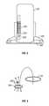
- FIG. 2shows a cross section of the FIG. 1 embodiment
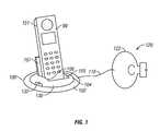
- FIG. 3shows how the base of the FIG. 1 embodiment can repeat the signal
- FIG. 4shows a second embodiment
- FIG. 5shows a third embodiment.
- a first embodimentdiscloses a wireless power station for a portable electronic device, e.g. a cordless phone, with reference to FIG. 1 .
- the term “wireless power station”is used to refer to a device that wirelessly transmits power that can either provide power to a device, or can charge a rechargeable battery within that device.
- the device 100can include a base 102 which has an antenna 104 incorporated therein.
- the antenna 104can receive power via magnetically coupled resonance, shown generically as 110 , from a transmitter of magnetic power 120 that is remote from the antenna 104 .
- the transmitter 120can produce magnetic fields as disclosed in our co-pending applications, and may include loosely coupled resonant loop/coil antennas that are preferably of high-quality factor e.g. quality factor Q larger than 500 . These devices may operate in either a low-frequency range or a high frequency range.
- FIG. 2illustrates a cross-section of the embodiment shown in FIG. 1 .
- the phone 99is mounted on the base 100 .
- 104shows a cross-section of the loop/coil antenna that is integrated into the wireless charging station. This antenna receives wirelessly power from the remote transmitter 120 .
- the integrated coil in the charging baseacts as a parasitic antenna that relays and in essence focuses the magnetically-generated power to a coil form antenna 220 integrated into the phone 99 .
- One advantage of this embodimentis that the phone 99 can then operate as a wireless receiver of power with or without the charging base.
- the charging basebecomes a system that allows operation more effectively via repeating of the magnetic energy.
- the antenna 220may be an integrated ferrite Rod antenna formed of a spool wound coil 222 and a capacitive device 224 in series with the spool wound coil.
- the inductance and capacitancetogether form a circuit that has an LC constant which is substantially resonant with the frequency used by the transmitter 120 , and as repeated by the antenna 104 .
- FIG. 2 embodimentAn advantage of FIG. 2 embodiment is that the form factor of the structures fit well within the space provided.
- the loop coil antenna 104is round in cross-section, and fits into the round cross section base 100 .
- the coil antenna 220is straight and cylindrical, and fits well into the straight body of the phone. Other shaped devices can of course be used.
- FIG. 3illustrates how the primary antenna 122 of the transmitter produces magnetic power that have electrical energy therein. This is transmitted via magnetic field coupling to a secondary antenna 104 that is integrated into the base of the power station 100 . This relays the power again via magnetic field coupling to the tertiary antenna 220 which is within the portable device. This forms a locally increased field due to the mutual coupling.
- the portable devicemay also receive power directly from the base station.
- the effect of the secondary antennamay be considered as that of a parasitic antenna locally magnifying the magnetic field in the vicinity of the charging station, increasing the overall efficiency of the receive antenna in the portable device. Therefore the embodiment of FIG. 2 may increase the distance and/or efficiency and/or power density of a wireless power station.
- the same portable device 99may also receive electrical energy directly from the power base station 120 .
- the repeating station of the first embodimentmay be most useful when used to obtain power at longer distances or otherwise fringe areas.
- the magnetic coupling between charging station and portable devicemay have certain advantages compared to the conductive coupling using electrical contacts (the classical solution). For example, contacts in electrical charging may become soiled or oxidized. Also, an electronic charging device typically is only usable with one device, into which the connector mates. A magnetic coupled charging station may be configured to charge e.g. different types of wireless power-enabled cordless phones.
- the portable devicesuch as 99 is formed in a case such as 101 .
- the casehas outer dimensions.
- the base 100has a holding portion 105 for the portable device.
- the holding portion 105includes surfaces such as 106 that are sized in a way that hold the case in place. For example, this may only hold the case on the bottom as near the surfaces 106 in FIG. 1 .
- Many different portable devicescan fit within the opening 105 . However, by holding the device 99 in a specified location, the efficiency of coupling magnetically between the antenna 104 and an antenna in the portable device may be improved.
- the portable deviceis described as being portable phone such as a cellular phone.
- the portable devicemay be a personal digital assistant such as PDA, a portable computer such as a laptop or other portable computer, a media player, such as an iPod or others, or other portable electronic device that operates from stored power.
- the antenna 104includes an inductive loop coil 130 , in series with a capacitor 132 .
- the coil and capacitorare selected to have high Q values, for example to provide a Q greater than 500 and even more preferably greater than 1000.
- the LC value of the coilis tuned to be substantially resonant with the transmission value from the transmitter 120 .
- a loop antennais used which is integrated as close to the outer perimeter of the base 100 as possible.
- the basehas a substantially disk shaped an outer perimeter. This allows the use of a round antenna.
- the disc outer perimetermay be any shape, and in fact a rectangular outer shape base may be used with a rectangular shaped antenna.
- Embodiment 2 depicted in FIG. 4is similar to embodiment 1 with a base 400 , antenna 402 . Electrical energy received by the wireless charging station is forwarded to the portable device 99 using conductive coupling over contacts 410 , 412 .
- Embodiment 3depicted in FIG. 5 , a charging station 500 which receives power through a wired connection 510 , e.g. directly from the 110/220 V mains or from a wall plug power supply as in classical solutions. This may use the same kind of portable device 99 as in the first embodiment.
- the poweris magnetically modulated and coupled to the antenna 220 based on magnetic coupled resonance.
Landscapes
- Engineering & Computer Science (AREA)
- Computer Networks & Wireless Communication (AREA)
- Power Engineering (AREA)
- Charge And Discharge Circuits For Batteries Or The Like (AREA)
Abstract
Description
Claims (25)
Priority Applications (2)
| Application Number | Priority Date | Filing Date | Title |
|---|---|---|---|
| US12/353,851US8294300B2 (en) | 2008-01-14 | 2009-01-14 | Wireless powering and charging station |
| US13/651,324US20130038138A1 (en) | 2008-01-14 | 2012-10-12 | Wireless powering and charging station |
Applications Claiming Priority (2)
| Application Number | Priority Date | Filing Date | Title |
|---|---|---|---|
| US2100108P | 2008-01-14 | 2008-01-14 | |
| US12/353,851US8294300B2 (en) | 2008-01-14 | 2009-01-14 | Wireless powering and charging station |
Related Child Applications (1)
| Application Number | Title | Priority Date | Filing Date |
|---|---|---|---|
| US13/651,324ContinuationUS20130038138A1 (en) | 2008-01-14 | 2012-10-12 | Wireless powering and charging station |
Publications (2)
| Publication Number | Publication Date |
|---|---|
| US20090179502A1 US20090179502A1 (en) | 2009-07-16 |
| US8294300B2true US8294300B2 (en) | 2012-10-23 |
Family
ID=40850030
Family Applications (2)
| Application Number | Title | Priority Date | Filing Date |
|---|---|---|---|
| US12/353,851Active2029-02-10US8294300B2 (en) | 2008-01-14 | 2009-01-14 | Wireless powering and charging station |
| US13/651,324AbandonedUS20130038138A1 (en) | 2008-01-14 | 2012-10-12 | Wireless powering and charging station |
Family Applications After (1)
| Application Number | Title | Priority Date | Filing Date |
|---|---|---|---|
| US13/651,324AbandonedUS20130038138A1 (en) | 2008-01-14 | 2012-10-12 | Wireless powering and charging station |
Country Status (1)
| Country | Link |
|---|---|
| US (2) | US8294300B2 (en) |
Cited By (17)
| Publication number | Priority date | Publication date | Assignee | Title |
|---|---|---|---|---|
| US20110270462A1 (en)* | 2008-11-14 | 2011-11-03 | Toyota Jidosha Kabushiki Kaisha | Contactless power supply system and control method thereof |
| US20110278945A1 (en)* | 2010-05-13 | 2011-11-17 | Qualcomm Incorporated | Resonance detection and control within a wireless power system |
| US20130147427A1 (en)* | 2011-09-07 | 2013-06-13 | Solace Power Inc. | Wireless electric field power transmission system and method |
| US20160099606A1 (en)* | 2014-10-03 | 2016-04-07 | Robert Bosch Gmbh | Inductive Charging Holster for Power Tool |
| US20160111892A1 (en)* | 2014-10-16 | 2016-04-21 | Nxp B.V. | Front-end circuits for wireless power receivers, wireless chargers and wireless charging |
| WO2016106183A1 (en)* | 2014-12-24 | 2016-06-30 | Robert Bosch Gmbh | Inductive charging holster for power tools in mobile applications |
| US20170098951A1 (en)* | 2015-10-01 | 2017-04-06 | Motorola Mobility Llc | Wireless charging architecture for mobile communication device with single-piece metal housing |
| US9685699B2 (en) | 2013-05-21 | 2017-06-20 | Microsoft Technology Licensing, Llc | Integrated antenna for wireless communications and wireless charging |
| US9979206B2 (en) | 2012-09-07 | 2018-05-22 | Solace Power Inc. | Wireless electric field power transfer system, method, transmitter and receiver therefor |
| US10033225B2 (en) | 2012-09-07 | 2018-07-24 | Solace Power Inc. | Wireless electric field power transmission system, transmitter and receiver therefor and method of wirelessly transferring power |
| US10455728B2 (en)* | 2012-07-06 | 2019-10-22 | Gentherm Incorporated | Systems and methods for thermoelectrically cooling inductive charging stations |
| US10463572B2 (en) | 2017-07-07 | 2019-11-05 | Neuroderm, Ltd. | Device for subcutaneous delivery of fluid medicament |
| US11000067B1 (en) | 2020-10-05 | 2021-05-11 | Puff Corporation | Portable electronic vaporizing device |
| USD944728S1 (en) | 2020-10-05 | 2022-03-01 | Puff Corporation | Charging station |
| USD949310S1 (en) | 2020-10-05 | 2022-04-19 | Puff Corporation | Electronic vaporizer base |
| US11779697B2 (en) | 2017-07-07 | 2023-10-10 | Neuroderm, Ltd. | Device for subcutaneous delivery of fluid medicament |
| US12389939B2 (en) | 2021-09-28 | 2025-08-19 | Puff Corporation | Portable pipe assembly |
Families Citing this family (135)
| Publication number | Priority date | Publication date | Assignee | Title |
|---|---|---|---|---|
| US7825543B2 (en) | 2005-07-12 | 2010-11-02 | Massachusetts Institute Of Technology | Wireless energy transfer |
| CN101860089B (en) | 2005-07-12 | 2013-02-06 | 麻省理工学院 | wireless non-radiative energy transfer |
| JP4855150B2 (en)* | 2006-06-09 | 2012-01-18 | 株式会社トプコン | Fundus observation apparatus, ophthalmic image processing apparatus, and ophthalmic image processing program |
| US9421388B2 (en) | 2007-06-01 | 2016-08-23 | Witricity Corporation | Power generation for implantable devices |
| US8115448B2 (en) | 2007-06-01 | 2012-02-14 | Michael Sasha John | Systems and methods for wireless power |
| US8487479B2 (en)* | 2008-02-24 | 2013-07-16 | Qualcomm Incorporated | Ferrite antennas for wireless power transfer |
| US20090284369A1 (en) | 2008-05-13 | 2009-11-19 | Qualcomm Incorporated | Transmit power control for a wireless charging system |
| CN102099958B (en)* | 2008-05-14 | 2013-12-25 | 麻省理工学院 | Wireless power transfer including interference enhancement |
| US8947041B2 (en)* | 2008-09-02 | 2015-02-03 | Qualcomm Incorporated | Bidirectional wireless power transmission |
| US9246336B2 (en) | 2008-09-27 | 2016-01-26 | Witricity Corporation | Resonator optimizations for wireless energy transfer |
| US8946938B2 (en) | 2008-09-27 | 2015-02-03 | Witricity Corporation | Safety systems for wireless energy transfer in vehicle applications |
| US8922066B2 (en) | 2008-09-27 | 2014-12-30 | Witricity Corporation | Wireless energy transfer with multi resonator arrays for vehicle applications |
| US9544683B2 (en) | 2008-09-27 | 2017-01-10 | Witricity Corporation | Wirelessly powered audio devices |
| US8587153B2 (en) | 2008-09-27 | 2013-11-19 | Witricity Corporation | Wireless energy transfer using high Q resonators for lighting applications |
| US8723366B2 (en) | 2008-09-27 | 2014-05-13 | Witricity Corporation | Wireless energy transfer resonator enclosures |
| US9184595B2 (en) | 2008-09-27 | 2015-11-10 | Witricity Corporation | Wireless energy transfer in lossy environments |
| US9065423B2 (en) | 2008-09-27 | 2015-06-23 | Witricity Corporation | Wireless energy distribution system |
| US9093853B2 (en) | 2008-09-27 | 2015-07-28 | Witricity Corporation | Flexible resonator attachment |
| US8686598B2 (en) | 2008-09-27 | 2014-04-01 | Witricity Corporation | Wireless energy transfer for supplying power and heat to a device |
| US8569914B2 (en) | 2008-09-27 | 2013-10-29 | Witricity Corporation | Wireless energy transfer using object positioning for improved k |
| US8497601B2 (en) | 2008-09-27 | 2013-07-30 | Witricity Corporation | Wireless energy transfer converters |
| US8957549B2 (en) | 2008-09-27 | 2015-02-17 | Witricity Corporation | Tunable wireless energy transfer for in-vehicle applications |
| US8410636B2 (en) | 2008-09-27 | 2013-04-02 | Witricity Corporation | Low AC resistance conductor designs |
| US9744858B2 (en) | 2008-09-27 | 2017-08-29 | Witricity Corporation | System for wireless energy distribution in a vehicle |
| US9106203B2 (en) | 2008-09-27 | 2015-08-11 | Witricity Corporation | Secure wireless energy transfer in medical applications |
| US8552592B2 (en) | 2008-09-27 | 2013-10-08 | Witricity Corporation | Wireless energy transfer with feedback control for lighting applications |
| US9105959B2 (en) | 2008-09-27 | 2015-08-11 | Witricity Corporation | Resonator enclosure |
| US8928276B2 (en) | 2008-09-27 | 2015-01-06 | Witricity Corporation | Integrated repeaters for cell phone applications |
| US8772973B2 (en) | 2008-09-27 | 2014-07-08 | Witricity Corporation | Integrated resonator-shield structures |
| US8643326B2 (en) | 2008-09-27 | 2014-02-04 | Witricity Corporation | Tunable wireless energy transfer systems |
| US8466583B2 (en) | 2008-09-27 | 2013-06-18 | Witricity Corporation | Tunable wireless energy transfer for outdoor lighting applications |
| US9396867B2 (en) | 2008-09-27 | 2016-07-19 | Witricity Corporation | Integrated resonator-shield structures |
| US9601270B2 (en) | 2008-09-27 | 2017-03-21 | Witricity Corporation | Low AC resistance conductor designs |
| US9318922B2 (en) | 2008-09-27 | 2016-04-19 | Witricity Corporation | Mechanically removable wireless power vehicle seat assembly |
| US8937408B2 (en) | 2008-09-27 | 2015-01-20 | Witricity Corporation | Wireless energy transfer for medical applications |
| US8304935B2 (en) | 2008-09-27 | 2012-11-06 | Witricity Corporation | Wireless energy transfer using field shaping to reduce loss |
| US8629578B2 (en) | 2008-09-27 | 2014-01-14 | Witricity Corporation | Wireless energy transfer systems |
| US8692412B2 (en) | 2008-09-27 | 2014-04-08 | Witricity Corporation | Temperature compensation in a wireless transfer system |
| US8461722B2 (en) | 2008-09-27 | 2013-06-11 | Witricity Corporation | Wireless energy transfer using conducting surfaces to shape field and improve K |
| US9515494B2 (en) | 2008-09-27 | 2016-12-06 | Witricity Corporation | Wireless power system including impedance matching network |
| US8598743B2 (en) | 2008-09-27 | 2013-12-03 | Witricity Corporation | Resonator arrays for wireless energy transfer |
| US8471410B2 (en) | 2008-09-27 | 2013-06-25 | Witricity Corporation | Wireless energy transfer over distance using field shaping to improve the coupling factor |
| US9601266B2 (en) | 2008-09-27 | 2017-03-21 | Witricity Corporation | Multiple connected resonators with a single electronic circuit |
| US9160203B2 (en) | 2008-09-27 | 2015-10-13 | Witricity Corporation | Wireless powered television |
| US8324759B2 (en) | 2008-09-27 | 2012-12-04 | Witricity Corporation | Wireless energy transfer using magnetic materials to shape field and reduce loss |
| US8476788B2 (en) | 2008-09-27 | 2013-07-02 | Witricity Corporation | Wireless energy transfer with high-Q resonators using field shaping to improve K |
| US8901779B2 (en) | 2008-09-27 | 2014-12-02 | Witricity Corporation | Wireless energy transfer with resonator arrays for medical applications |
| US8901778B2 (en) | 2008-09-27 | 2014-12-02 | Witricity Corporation | Wireless energy transfer with variable size resonators for implanted medical devices |
| US8963488B2 (en) | 2008-09-27 | 2015-02-24 | Witricity Corporation | Position insensitive wireless charging |
| EP3179640A1 (en) | 2008-09-27 | 2017-06-14 | WiTricity Corporation | Wireless energy transfer systems |
| US8912687B2 (en) | 2008-09-27 | 2014-12-16 | Witricity Corporation | Secure wireless energy transfer for vehicle applications |
| US8692410B2 (en) | 2008-09-27 | 2014-04-08 | Witricity Corporation | Wireless energy transfer with frequency hopping |
| US8461720B2 (en) | 2008-09-27 | 2013-06-11 | Witricity Corporation | Wireless energy transfer using conducting surfaces to shape fields and reduce loss |
| US8400017B2 (en) | 2008-09-27 | 2013-03-19 | Witricity Corporation | Wireless energy transfer for computer peripheral applications |
| US8933594B2 (en) | 2008-09-27 | 2015-01-13 | Witricity Corporation | Wireless energy transfer for vehicles |
| US9577436B2 (en) | 2008-09-27 | 2017-02-21 | Witricity Corporation | Wireless energy transfer for implantable devices |
| US8669676B2 (en) | 2008-09-27 | 2014-03-11 | Witricity Corporation | Wireless energy transfer across variable distances using field shaping with magnetic materials to improve the coupling factor |
| US9035499B2 (en) | 2008-09-27 | 2015-05-19 | Witricity Corporation | Wireless energy transfer for photovoltaic panels |
| US8461721B2 (en) | 2008-09-27 | 2013-06-11 | Witricity Corporation | Wireless energy transfer using object positioning for low loss |
| US8907531B2 (en) | 2008-09-27 | 2014-12-09 | Witricity Corporation | Wireless energy transfer with variable size resonators for medical applications |
| US8482158B2 (en) | 2008-09-27 | 2013-07-09 | Witricity Corporation | Wireless energy transfer using variable size resonators and system monitoring |
| US8947186B2 (en) | 2008-09-27 | 2015-02-03 | Witricity Corporation | Wireless energy transfer resonator thermal management |
| US8487480B1 (en) | 2008-09-27 | 2013-07-16 | Witricity Corporation | Wireless energy transfer resonator kit |
| US9601261B2 (en) | 2008-09-27 | 2017-03-21 | Witricity Corporation | Wireless energy transfer using repeater resonators |
| US8441154B2 (en) | 2008-09-27 | 2013-05-14 | Witricity Corporation | Multi-resonator wireless energy transfer for exterior lighting |
| US8587155B2 (en) | 2008-09-27 | 2013-11-19 | Witricity Corporation | Wireless energy transfer using repeater resonators |
| US8362651B2 (en) | 2008-10-01 | 2013-01-29 | Massachusetts Institute Of Technology | Efficient near-field wireless energy transfer using adiabatic system variations |
| US20100201312A1 (en)* | 2009-02-10 | 2010-08-12 | Qualcomm Incorporated | Wireless power transfer for portable enclosures |
| US9013141B2 (en)* | 2009-04-28 | 2015-04-21 | Qualcomm Incorporated | Parasitic devices for wireless power transfer |
| US8655272B2 (en) | 2009-07-07 | 2014-02-18 | Nokia Corporation | Wireless charging coil filtering |
| US20110057606A1 (en)* | 2009-09-04 | 2011-03-10 | Nokia Corpation | Safety feature for wireless charger |
| JP5577896B2 (en)* | 2009-10-07 | 2014-08-27 | Tdk株式会社 | Wireless power supply apparatus and wireless power transmission system |
| JP5476917B2 (en)* | 2009-10-16 | 2014-04-23 | Tdk株式会社 | Wireless power feeding device, wireless power receiving device, and wireless power transmission system |
| JP5471283B2 (en)* | 2009-10-19 | 2014-04-16 | Tdk株式会社 | Wireless power feeding device, wireless power receiving device, and wireless power transmission system |
| US8829727B2 (en) | 2009-10-30 | 2014-09-09 | Tdk Corporation | Wireless power feeder, wireless power transmission system, and table and table lamp using the same |
| US8427101B2 (en)* | 2009-11-18 | 2013-04-23 | Nokia Corporation | Wireless energy repeater |
| US20110156487A1 (en)* | 2009-12-30 | 2011-06-30 | Koon Hoo Teo | Wireless Energy Transfer with Energy Relays |
| EP2367263B1 (en) | 2010-03-19 | 2019-05-01 | TDK Corporation | Wireless power feeder, wireless power receiver, and wireless power transmission system |
| US8909966B2 (en)* | 2010-03-26 | 2014-12-09 | Advantest Corporation | Wireless power supply apparatus |
| US8934857B2 (en)* | 2010-05-14 | 2015-01-13 | Qualcomm Incorporated | Controlling field distribution of a wireless power transmitter |
| US8729736B2 (en) | 2010-07-02 | 2014-05-20 | Tdk Corporation | Wireless power feeder and wireless power transmission system |
| US8829726B2 (en) | 2010-07-02 | 2014-09-09 | Tdk Corporation | Wireless power feeder and wireless power transmission system |
| US8829729B2 (en) | 2010-08-18 | 2014-09-09 | Tdk Corporation | Wireless power feeder, wireless power receiver, and wireless power transmission system |
| US8772977B2 (en) | 2010-08-25 | 2014-07-08 | Tdk Corporation | Wireless power feeder, wireless power transmission system, and table and table lamp using the same |
| US9602168B2 (en) | 2010-08-31 | 2017-03-21 | Witricity Corporation | Communication in wireless energy transfer systems |
| US9058928B2 (en) | 2010-12-14 | 2015-06-16 | Tdk Corporation | Wireless power feeder and wireless power transmission system |
| US9143010B2 (en) | 2010-12-28 | 2015-09-22 | Tdk Corporation | Wireless power transmission system for selectively powering one or more of a plurality of receivers |
| US8664803B2 (en) | 2010-12-28 | 2014-03-04 | Tdk Corporation | Wireless power feeder, wireless power receiver, and wireless power transmission system |
| US8669677B2 (en) | 2010-12-28 | 2014-03-11 | Tdk Corporation | Wireless power feeder, wireless power receiver, and wireless power transmission system |
| US8800738B2 (en) | 2010-12-28 | 2014-08-12 | Tdk Corporation | Wireless power feeder and wireless power receiver |
| JP5838562B2 (en)* | 2011-02-17 | 2016-01-06 | 富士通株式会社 | Wireless power transmission device and wireless power transmission system |
| US8742627B2 (en) | 2011-03-01 | 2014-06-03 | Tdk Corporation | Wireless power feeder |
| US8970069B2 (en) | 2011-03-28 | 2015-03-03 | Tdk Corporation | Wireless power receiver and wireless power transmission system |
| FR2974259B1 (en)* | 2011-04-18 | 2013-06-07 | Commissariat Energie Atomique | RECEIVER POWERED BY AN INDUCTIVE TYPE WIRELESS INTERFACE |
| US9948145B2 (en) | 2011-07-08 | 2018-04-17 | Witricity Corporation | Wireless power transfer for a seat-vest-helmet system |
| CN108110907B (en) | 2011-08-04 | 2022-08-02 | 韦特里西提公司 | Tunable wireless power supply architecture |
| WO2013031025A1 (en) | 2011-09-02 | 2013-03-07 | 富士通株式会社 | Power relay |
| EP2754222B1 (en) | 2011-09-09 | 2015-11-18 | Witricity Corporation | Foreign object detection in wireless energy transfer systems |
| US20130062966A1 (en) | 2011-09-12 | 2013-03-14 | Witricity Corporation | Reconfigurable control architectures and algorithms for electric vehicle wireless energy transfer systems |
| US9318257B2 (en) | 2011-10-18 | 2016-04-19 | Witricity Corporation | Wireless energy transfer for packaging |
| CA2853824A1 (en) | 2011-11-04 | 2013-05-10 | Witricity Corporation | Wireless energy transfer modeling tool |
| JP2015508987A (en) | 2012-01-26 | 2015-03-23 | ワイトリシティ コーポレーションWitricity Corporation | Wireless energy transmission with reduced field |
| US9343922B2 (en) | 2012-06-27 | 2016-05-17 | Witricity Corporation | Wireless energy transfer for rechargeable batteries |
| US9287607B2 (en) | 2012-07-31 | 2016-03-15 | Witricity Corporation | Resonator fine tuning |
| US9595378B2 (en) | 2012-09-19 | 2017-03-14 | Witricity Corporation | Resonator enclosure |
| EP2909912B1 (en) | 2012-10-19 | 2022-08-10 | WiTricity Corporation | Foreign object detection in wireless energy transfer systems |
| US9842684B2 (en) | 2012-11-16 | 2017-12-12 | Witricity Corporation | Systems and methods for wireless power system with improved performance and/or ease of use |
| TWM457910U (en)* | 2013-01-25 | 2013-07-21 | Ceramate Technical Co Ltd | Multi-directional wireless power supply device using arc coil coupling power |
| US9779870B2 (en) | 2013-05-20 | 2017-10-03 | Nokia Technologies Oy | Method and apparatus for transferring electromagnetic power |
| US9857821B2 (en) | 2013-08-14 | 2018-01-02 | Witricity Corporation | Wireless power transfer frequency adjustment |
| US20150097519A1 (en)* | 2013-10-08 | 2015-04-09 | Cyberpower Systems, Inc. | Wireless charger with coil position adjustability |
| US9780573B2 (en) | 2014-02-03 | 2017-10-03 | Witricity Corporation | Wirelessly charged battery system |
| US9952266B2 (en) | 2014-02-14 | 2018-04-24 | Witricity Corporation | Object detection for wireless energy transfer systems |
| US9842687B2 (en) | 2014-04-17 | 2017-12-12 | Witricity Corporation | Wireless power transfer systems with shaped magnetic components |
| US9892849B2 (en) | 2014-04-17 | 2018-02-13 | Witricity Corporation | Wireless power transfer systems with shield openings |
| US9837860B2 (en) | 2014-05-05 | 2017-12-05 | Witricity Corporation | Wireless power transmission systems for elevators |
| JP2017518018A (en) | 2014-05-07 | 2017-06-29 | ワイトリシティ コーポレーションWitricity Corporation | Foreign object detection in wireless energy transmission systems |
| US9954375B2 (en) | 2014-06-20 | 2018-04-24 | Witricity Corporation | Wireless power transfer systems for surfaces |
| US10574091B2 (en) | 2014-07-08 | 2020-02-25 | Witricity Corporation | Enclosures for high power wireless power transfer systems |
| CN107258046B (en) | 2014-07-08 | 2020-07-17 | 无线电力公司 | Resonator equalization in wireless power transfer systems |
| TW201605142A (en)* | 2014-07-30 | 2016-02-01 | 鴻海精密工業股份有限公司 | Vehicle wireless charging device |
| US9843217B2 (en) | 2015-01-05 | 2017-12-12 | Witricity Corporation | Wireless energy transfer for wearables |
| US20160372959A1 (en)* | 2015-06-16 | 2016-12-22 | Zagg Intellectual Property Holding Co. Inc. | Wireless Power Transmitter, Charging Dock and Speaker System |
| US10084321B2 (en) | 2015-07-02 | 2018-09-25 | Qualcomm Incorporated | Controlling field distribution of a wireless power transmitter |
| US10420175B2 (en) | 2015-09-25 | 2019-09-17 | Intel Corporation | Wireless warmers |
| US10248899B2 (en) | 2015-10-06 | 2019-04-02 | Witricity Corporation | RFID tag and transponder detection in wireless energy transfer systems |
| US9929721B2 (en) | 2015-10-14 | 2018-03-27 | Witricity Corporation | Phase and amplitude detection in wireless energy transfer systems |
| WO2017070227A1 (en) | 2015-10-19 | 2017-04-27 | Witricity Corporation | Foreign object detection in wireless energy transfer systems |
| WO2017070009A1 (en) | 2015-10-22 | 2017-04-27 | Witricity Corporation | Dynamic tuning in wireless energy transfer systems |
| US10075019B2 (en) | 2015-11-20 | 2018-09-11 | Witricity Corporation | Voltage source isolation in wireless power transfer systems |
| WO2017136491A1 (en) | 2016-02-02 | 2017-08-10 | Witricity Corporation | Controlling wireless power transfer systems |
| CN114123540B (en) | 2016-02-08 | 2024-08-20 | 韦特里西提公司 | Variable capacitance device and high-power wireless energy transmission system |
| US9660487B1 (en)* | 2016-06-13 | 2017-05-23 | Megau LLC | Intelligent wireless power transferring system with automatic positioning |
| WO2019006376A1 (en) | 2017-06-29 | 2019-01-03 | Witricity Corporation | Protection and control of wireless power systems |
| WO2021114183A1 (en)* | 2019-12-12 | 2021-06-17 | 王宾宇 | Wireless charger |
Citations (33)
| Publication number | Priority date | Publication date | Assignee | Title |
|---|---|---|---|---|
| US5959433A (en)* | 1997-08-22 | 1999-09-28 | Centurion Intl., Inc. | Universal inductive battery charger system |
| US6134421A (en)* | 1997-09-10 | 2000-10-17 | Qualcomm Incorporated | RF coupler for wireless telephone cradle |
| US6172608B1 (en)* | 1996-06-19 | 2001-01-09 | Integrated Silicon Design Pty. Ltd. | Enhanced range transponder system |
| US6590394B2 (en)* | 2001-09-28 | 2003-07-08 | Varian, Inc. | NMR probe with enhanced power handling ability |
| US20040130425A1 (en)* | 2002-08-12 | 2004-07-08 | Tal Dayan | Enhanced RF wireless adaptive power provisioning system for small devices |
| US6856819B2 (en)* | 2000-03-07 | 2005-02-15 | Nec Corporation | Portable wireless unit |
| US20050104453A1 (en)* | 2003-10-17 | 2005-05-19 | Firefly Power Technologies, Inc. | Method and apparatus for a wireless power supply |
| US20050127867A1 (en) | 2003-12-12 | 2005-06-16 | Microsoft Corporation | Inductively charged battery pack |
| US20050131495A1 (en) | 2002-06-28 | 2005-06-16 | Jordi Parramon | Systems and methods for providing power to a battery in an implantable stimulator |
| US6912137B2 (en)* | 2001-11-30 | 2005-06-28 | Friwo Geraetebau Gmbh | Inductive contactless power transmitter |
| US7046146B2 (en)* | 2000-05-17 | 2006-05-16 | Stmicroelectronics S.A. | Electromagnetic field generation device for a transponder |
| US7180503B2 (en)* | 2001-12-04 | 2007-02-20 | Intel Corporation | Inductive power source for peripheral devices |
| US20070222542A1 (en) | 2005-07-12 | 2007-09-27 | Joannopoulos John D | Wireless non-radiative energy transfer |
| US20080067874A1 (en)* | 2006-09-14 | 2008-03-20 | Ryan Tseng | Method and apparatus for wireless power transmission |
| US20080191897A1 (en) | 2005-11-16 | 2008-08-14 | Mccollough Norman D | Photoelectric controller for electric street lighting |
| US20090015075A1 (en)* | 2007-07-09 | 2009-01-15 | Nigel Power, Llc | Wireless Energy Transfer Using Coupled Antennas |
| US7495414B2 (en)* | 2005-07-25 | 2009-02-24 | Convenient Power Limited | Rechargeable battery circuit and structure for compatibility with a planar inductive charging platform |
| US20090058189A1 (en)* | 2007-08-13 | 2009-03-05 | Nigelpower, Llc | Long range low frequency resonator and materials |
| US7515049B2 (en)* | 2006-06-08 | 2009-04-07 | Asyst Technologies, Inc. | Extended read range RFID system |
| US7525283B2 (en)* | 2002-05-13 | 2009-04-28 | Access Business Group International Llc | Contact-less power transfer |
| US20090134712A1 (en)* | 2007-11-28 | 2009-05-28 | Nigel Power Llc | Wireless Power Range Increase Using Parasitic Antennas |
| US20090160261A1 (en)* | 2007-12-19 | 2009-06-25 | Nokia Corporation | Wireless energy transfer |
| US7576514B2 (en)* | 2002-06-10 | 2009-08-18 | Cityu Research Limited | Planar inductive battery charging system |
| US20090212636A1 (en)* | 2008-01-10 | 2009-08-27 | Nigel Power Llc | Wireless desktop IT environment |
| US20090243397A1 (en)* | 2008-03-05 | 2009-10-01 | Nigel Power, Llc | Packaging and Details of a Wireless Power device |
| US7633263B2 (en)* | 2006-08-11 | 2009-12-15 | Sanyo Electric Co., Ltd. | Battery charger |
| WO2010014634A2 (en)* | 2008-07-28 | 2010-02-04 | Qualcomm Incorporated | Wireless power transmission for electronic devices |
| US20100038970A1 (en)* | 2008-04-21 | 2010-02-18 | Nigel Power, Llc | Short Range Efficient Wireless Power Transfer |
| US20100127660A1 (en)* | 2008-08-19 | 2010-05-27 | Qualcomm Incorporated | Wireless power transmission for portable wireless power charging |
| US7825543B2 (en) | 2005-07-12 | 2010-11-02 | Massachusetts Institute Of Technology | Wireless energy transfer |
| US20100277120A1 (en)* | 2009-04-28 | 2010-11-04 | Qualcomm Incorporated | Parasitic devices for wireless power transfer |
| US20110121660A1 (en)* | 2008-06-02 | 2011-05-26 | Powermat Ltd. | Appliance mounted power outlets |
| US20110304216A1 (en)* | 2010-06-10 | 2011-12-15 | Access Business Group International Llc | Coil configurations for inductive power transer |
Family Cites Families (25)
| Publication number | Priority date | Publication date | Assignee | Title |
|---|---|---|---|---|
| US3840795A (en)* | 1964-07-07 | 1974-10-08 | Sunbeam Corp | Hand held battery operated device and charging means therefor |
| US4751513A (en)* | 1986-05-02 | 1988-06-14 | Rca Corporation | Light controlled antennas |
| US5621422A (en)* | 1994-08-22 | 1997-04-15 | Wang-Tripp Corporation | Spiral-mode microstrip (SMM) antennas and associated methods for exciting, extracting and multiplexing the various spiral modes |
| US7263388B2 (en)* | 2001-06-29 | 2007-08-28 | Nokia Corporation | Charging system for portable equipment |
| GB2387969B (en)* | 2002-04-13 | 2005-11-30 | Maurice Clifford Hately | Radio antennas |
| US6972543B1 (en)* | 2003-08-21 | 2005-12-06 | Stryker Corporation | Series resonant inductive charging circuit |
| JP3982476B2 (en)* | 2003-10-01 | 2007-09-26 | ソニー株式会社 | Communications system |
| US6839035B1 (en)* | 2003-10-07 | 2005-01-04 | A.C.C. Systems | Magnetically coupled antenna range extender |
| GB2414121B (en)* | 2004-05-11 | 2008-04-02 | Splashpower Ltd | Controlling inductive power transfer systems |
| US7675197B2 (en)* | 2004-06-17 | 2010-03-09 | Auckland Uniservices Limited | Apparatus and method for inductive power transfer |
| US7211986B1 (en)* | 2004-07-01 | 2007-05-01 | Plantronics, Inc. | Inductive charging system |
| US7151357B2 (en)* | 2004-07-30 | 2006-12-19 | Kye Systems Corporation | Pulse frequency modulation for induction charge device |
| US20070072474A1 (en)* | 2005-04-27 | 2007-03-29 | Nigel Beasley | Flexible power adapter systems and methods |
| US7215284B2 (en)* | 2005-05-13 | 2007-05-08 | Lockheed Martin Corporation | Passive self-switching dual band array antenna |
| US7193578B1 (en)* | 2005-10-07 | 2007-03-20 | Lockhead Martin Corporation | Horn antenna array and methods for fabrication thereof |
| US7382636B2 (en)* | 2005-10-14 | 2008-06-03 | Access Business Group International Llc | System and method for powering a load |
| US8169185B2 (en)* | 2006-01-31 | 2012-05-01 | Mojo Mobility, Inc. | System and method for inductive charging of portable devices |
| WO2007131093A2 (en)* | 2006-05-05 | 2007-11-15 | University Of Pittsburgh-Of The Commonwealth System Of Higher Education | Wireless autonomous device data transmission |
| KR20110117732A (en)* | 2007-03-27 | 2011-10-27 | 메사추세츠 인스티튜트 오브 테크놀로지 | Wireless energy transfer |
| US8193764B2 (en)* | 2007-08-08 | 2012-06-05 | Jay Marketing Associates, Inc. | Wireless charging of electronic devices |
| US20090067198A1 (en)* | 2007-08-29 | 2009-03-12 | David Jeffrey Graham | Contactless power supply |
| CA2701394A1 (en)* | 2007-10-17 | 2009-04-23 | Access Business Group International Llc | Laptop and portable electronic device wireless power supply systems |
| JP5073517B2 (en)* | 2008-01-29 | 2012-11-14 | パナソニック株式会社 | MIMO antenna apparatus and wireless communication apparatus including the same |
| JP5533856B2 (en)* | 2009-03-30 | 2014-06-25 | 富士通株式会社 | Wireless power supply system, wireless power transmitting apparatus, and wireless power receiving apparatus |
| TWM393922U (en)* | 2010-07-19 | 2010-12-01 | ming-xiang Ye | Bidirectional wireless charge and discharge device |
- 2009
- 2009-01-14USUS12/353,851patent/US8294300B2/enactiveActive
- 2012
- 2012-10-12USUS13/651,324patent/US20130038138A1/ennot_activeAbandoned
Patent Citations (36)
| Publication number | Priority date | Publication date | Assignee | Title |
|---|---|---|---|---|
| US6172608B1 (en)* | 1996-06-19 | 2001-01-09 | Integrated Silicon Design Pty. Ltd. | Enhanced range transponder system |
| US5959433A (en)* | 1997-08-22 | 1999-09-28 | Centurion Intl., Inc. | Universal inductive battery charger system |
| US6134421A (en)* | 1997-09-10 | 2000-10-17 | Qualcomm Incorporated | RF coupler for wireless telephone cradle |
| US6856819B2 (en)* | 2000-03-07 | 2005-02-15 | Nec Corporation | Portable wireless unit |
| US7046146B2 (en)* | 2000-05-17 | 2006-05-16 | Stmicroelectronics S.A. | Electromagnetic field generation device for a transponder |
| US6590394B2 (en)* | 2001-09-28 | 2003-07-08 | Varian, Inc. | NMR probe with enhanced power handling ability |
| US6912137B2 (en)* | 2001-11-30 | 2005-06-28 | Friwo Geraetebau Gmbh | Inductive contactless power transmitter |
| US7180503B2 (en)* | 2001-12-04 | 2007-02-20 | Intel Corporation | Inductive power source for peripheral devices |
| US7525283B2 (en)* | 2002-05-13 | 2009-04-28 | Access Business Group International Llc | Contact-less power transfer |
| US7576514B2 (en)* | 2002-06-10 | 2009-08-18 | Cityu Research Limited | Planar inductive battery charging system |
| US20050131495A1 (en) | 2002-06-28 | 2005-06-16 | Jordi Parramon | Systems and methods for providing power to a battery in an implantable stimulator |
| US20040130425A1 (en)* | 2002-08-12 | 2004-07-08 | Tal Dayan | Enhanced RF wireless adaptive power provisioning system for small devices |
| US20050104453A1 (en)* | 2003-10-17 | 2005-05-19 | Firefly Power Technologies, Inc. | Method and apparatus for a wireless power supply |
| US20050127867A1 (en) | 2003-12-12 | 2005-06-16 | Microsoft Corporation | Inductively charged battery pack |
| US20070222542A1 (en) | 2005-07-12 | 2007-09-27 | Joannopoulos John D | Wireless non-radiative energy transfer |
| US20100277005A1 (en) | 2005-07-12 | 2010-11-04 | Aristeidis Karalis | Wireless powering and charging station |
| US7825543B2 (en) | 2005-07-12 | 2010-11-02 | Massachusetts Institute Of Technology | Wireless energy transfer |
| US7741734B2 (en) | 2005-07-12 | 2010-06-22 | Massachusetts Institute Of Technology | Wireless non-radiative energy transfer |
| US7495414B2 (en)* | 2005-07-25 | 2009-02-24 | Convenient Power Limited | Rechargeable battery circuit and structure for compatibility with a planar inductive charging platform |
| US20080191897A1 (en) | 2005-11-16 | 2008-08-14 | Mccollough Norman D | Photoelectric controller for electric street lighting |
| US7515049B2 (en)* | 2006-06-08 | 2009-04-07 | Asyst Technologies, Inc. | Extended read range RFID system |
| US7633263B2 (en)* | 2006-08-11 | 2009-12-15 | Sanyo Electric Co., Ltd. | Battery charger |
| US20080067874A1 (en)* | 2006-09-14 | 2008-03-20 | Ryan Tseng | Method and apparatus for wireless power transmission |
| US20090015075A1 (en)* | 2007-07-09 | 2009-01-15 | Nigel Power, Llc | Wireless Energy Transfer Using Coupled Antennas |
| US20090058189A1 (en)* | 2007-08-13 | 2009-03-05 | Nigelpower, Llc | Long range low frequency resonator and materials |
| US20090134712A1 (en)* | 2007-11-28 | 2009-05-28 | Nigel Power Llc | Wireless Power Range Increase Using Parasitic Antennas |
| US20090160261A1 (en)* | 2007-12-19 | 2009-06-25 | Nokia Corporation | Wireless energy transfer |
| US20100289449A1 (en)* | 2007-12-19 | 2010-11-18 | Harri Heikki Elo | Wireless energy transfer |
| US20090212636A1 (en)* | 2008-01-10 | 2009-08-27 | Nigel Power Llc | Wireless desktop IT environment |
| US20090243397A1 (en)* | 2008-03-05 | 2009-10-01 | Nigel Power, Llc | Packaging and Details of a Wireless Power device |
| US20100038970A1 (en)* | 2008-04-21 | 2010-02-18 | Nigel Power, Llc | Short Range Efficient Wireless Power Transfer |
| US20110121660A1 (en)* | 2008-06-02 | 2011-05-26 | Powermat Ltd. | Appliance mounted power outlets |
| WO2010014634A2 (en)* | 2008-07-28 | 2010-02-04 | Qualcomm Incorporated | Wireless power transmission for electronic devices |
| US20100127660A1 (en)* | 2008-08-19 | 2010-05-27 | Qualcomm Incorporated | Wireless power transmission for portable wireless power charging |
| US20100277120A1 (en)* | 2009-04-28 | 2010-11-04 | Qualcomm Incorporated | Parasitic devices for wireless power transfer |
| US20110304216A1 (en)* | 2010-06-10 | 2011-12-15 | Access Business Group International Llc | Coil configurations for inductive power transer |
Non-Patent Citations (4)
| Title |
|---|
| "Efficient wireless non-radiative mid-range energy transfer", MITpaper, publication and date unknown, believed to be 2007. |
| "Wireless Non-Radiative Energy Transfer", MIT paper, publication and date unknown, believed to be 2007. |
| "Wireless Power Transfer via Strongly Coupled Magnetic Resonances", Kurs et al, Science Express, Jun. 7, 2007. |
| "Wireless Power Transfer via Strongly Coupled Magnetic Resonances", Kurs et al, scimag.org, Jul. 6, 2007. |
Cited By (30)
| Publication number | Priority date | Publication date | Assignee | Title |
|---|---|---|---|---|
| US9172251B2 (en)* | 2008-11-14 | 2015-10-27 | Toyota Jidosha Kabushiki Kaisha | Controlling the wireless transmission of power based on the efficiency of power transmissions |
| US20110270462A1 (en)* | 2008-11-14 | 2011-11-03 | Toyota Jidosha Kabushiki Kaisha | Contactless power supply system and control method thereof |
| US9479225B2 (en)* | 2010-05-13 | 2016-10-25 | Qualcomm Incorporated | Resonance detection and control within a wireless power system |
| US20110278945A1 (en)* | 2010-05-13 | 2011-11-17 | Qualcomm Incorporated | Resonance detection and control within a wireless power system |
| US20130147427A1 (en)* | 2011-09-07 | 2013-06-13 | Solace Power Inc. | Wireless electric field power transmission system and method |
| US9653948B2 (en)* | 2011-09-07 | 2017-05-16 | Solace Power Inc. | Wireless resonant electric field power transfer system and method using high Q-factor coils |
| US10455728B2 (en)* | 2012-07-06 | 2019-10-22 | Gentherm Incorporated | Systems and methods for thermoelectrically cooling inductive charging stations |
| US9979206B2 (en) | 2012-09-07 | 2018-05-22 | Solace Power Inc. | Wireless electric field power transfer system, method, transmitter and receiver therefor |
| US10033225B2 (en) | 2012-09-07 | 2018-07-24 | Solace Power Inc. | Wireless electric field power transmission system, transmitter and receiver therefor and method of wirelessly transferring power |
| US9685699B2 (en) | 2013-05-21 | 2017-06-20 | Microsoft Technology Licensing, Llc | Integrated antenna for wireless communications and wireless charging |
| US10424942B2 (en) | 2014-09-05 | 2019-09-24 | Solace Power Inc. | Wireless electric field power transfer system, method, transmitter and receiver therefor |
| US20160099606A1 (en)* | 2014-10-03 | 2016-04-07 | Robert Bosch Gmbh | Inductive Charging Holster for Power Tool |
| US10381856B2 (en)* | 2014-10-03 | 2019-08-13 | Robert Bosch Tool Corporation | Inductive charging holster for power tool |
| US20160111892A1 (en)* | 2014-10-16 | 2016-04-21 | Nxp B.V. | Front-end circuits for wireless power receivers, wireless chargers and wireless charging |
| US9887576B2 (en) | 2014-12-24 | 2018-02-06 | Robert Bosch Tool Corporation | Inductive charging holster for power tools in mobile applications |
| CN107534301A (en)* | 2014-12-24 | 2018-01-02 | 罗伯特·博世有限公司 | Induction charging seat for the electric tool in Mobile solution |
| WO2016106183A1 (en)* | 2014-12-24 | 2016-06-30 | Robert Bosch Gmbh | Inductive charging holster for power tools in mobile applications |
| US20170098951A1 (en)* | 2015-10-01 | 2017-04-06 | Motorola Mobility Llc | Wireless charging architecture for mobile communication device with single-piece metal housing |
| US9882415B2 (en)* | 2015-10-01 | 2018-01-30 | Motorola Mobility Llc | Wireless charging architecture for mobile communication device with single piece metal housing |
| US10603430B2 (en) | 2017-07-07 | 2020-03-31 | Neuroderm, Ltd. | Device for subcutaneous delivery of fluid medicament |
| US10463787B2 (en) | 2017-07-07 | 2019-11-05 | Neuroderm, Ltd. | Device for subcutaneous delivery of fluid medicament |
| US10463572B2 (en) | 2017-07-07 | 2019-11-05 | Neuroderm, Ltd. | Device for subcutaneous delivery of fluid medicament |
| US11554210B2 (en) | 2017-07-07 | 2023-01-17 | Neuroderm, Ltd. | Device for subcutaneous delivery of fluid medicament |
| US11779697B2 (en) | 2017-07-07 | 2023-10-10 | Neuroderm, Ltd. | Device for subcutaneous delivery of fluid medicament |
| US11000067B1 (en) | 2020-10-05 | 2021-05-11 | Puff Corporation | Portable electronic vaporizing device |
| US11140924B1 (en) | 2020-10-05 | 2021-10-12 | Puff Corporation | Portable electronic vaporizing device |
| USD944728S1 (en) | 2020-10-05 | 2022-03-01 | Puff Corporation | Charging station |
| USD949310S1 (en) | 2020-10-05 | 2022-04-19 | Puff Corporation | Electronic vaporizer base |
| US11744295B2 (en) | 2020-10-05 | 2023-09-05 | Puff Corporation | Releasable cap for a vaporization assembly of a portable electronic vaporizing device |
| US12389939B2 (en) | 2021-09-28 | 2025-08-19 | Puff Corporation | Portable pipe assembly |
Also Published As
| Publication number | Publication date |
|---|---|
| US20090179502A1 (en) | 2009-07-16 |
| US20130038138A1 (en) | 2013-02-14 |
Similar Documents
| Publication | Publication Date | Title |
|---|---|---|
| US8294300B2 (en) | Wireless powering and charging station | |
| US9128687B2 (en) | Wireless desktop IT environment | |
| KR101572743B1 (en) | Short range efficient wireless power transfer | |
| US8854224B2 (en) | Conveying device information relating to wireless charging | |
| CN105844189B (en) | The optimization of wireless power device for charging the battery | |
| US9013141B2 (en) | Parasitic devices for wireless power transfer | |
| JP5557120B2 (en) | Inductive power receiver and mobile communication device provided with inductive power receiver | |
| US8541974B2 (en) | Movable magnetically resonant antenna for wireless charging | |
| US8766482B2 (en) | High efficiency and power transfer in wireless power magnetic resonators | |
| KR101545133B1 (en) | Wireless Power Transmission System for In-vivo Wireless Sensors and Method thereof | |
| US20110095617A1 (en) | Ferrite antennas for wireless power transfer | |
| US20090058189A1 (en) | Long range low frequency resonator and materials | |
| US11349345B2 (en) | Wireless power transmission device | |
| KR20100055069A (en) | Apparatus of wireless power transmission using high q near magnetic field resonator | |
| KR20110051272A (en) | Two-way wireless power transmission | |
| KR20120093365A (en) | Wireless power utilization in a local computing environment | |
| CN101828339A (en) | Wireless energy transfer using coupled antennas | |
| CN103370850A (en) | wireless power supply system | |
| KR20130047722A (en) | Wireless charging system in car for mobile phones and devices | |
| KR20180105655A (en) | Wireless power transmission in an electronic device with a tuned metallic body | |
| US10425049B2 (en) | Wireless electric power transmitter | |
| US20170163094A1 (en) | Coupled resonator in a metal back cover | |
| KR101883655B1 (en) | Wireless power receiver and method for controlling thereof |
Legal Events
| Date | Code | Title | Description |
|---|---|---|---|
| AS | Assignment | Owner name:NIGEL POWER, LLC, CALIFORNIA Free format text:ASSIGNMENT OF ASSIGNORS INTEREST;ASSIGNORS:COOK, NIGEL P;SIEBER, LUKAS;WIDMER, HANSPETER;REEL/FRAME:022470/0840;SIGNING DATES FROM 20090303 TO 20090316 Owner name:NIGEL POWER, LLC, CALIFORNIA Free format text:ASSIGNMENT OF ASSIGNORS INTEREST;ASSIGNORS:COOK, NIGEL P;SIEBER, LUKAS;WIDMER, HANSPETER;SIGNING DATES FROM 20090303 TO 20090316;REEL/FRAME:022470/0840 | |
| AS | Assignment | Owner name:QUALCOMM INCORPORATED, CALIFORNIA Free format text:ASSIGNMENT OF ASSIGNORS INTEREST;ASSIGNOR:NIGEL POWER LLC;REEL/FRAME:023445/0266 Effective date:20090519 Owner name:QUALCOMM INCORPORATED,CALIFORNIA Free format text:ASSIGNMENT OF ASSIGNORS INTEREST;ASSIGNOR:NIGEL POWER LLC;REEL/FRAME:023445/0266 Effective date:20090519 | |
| FEPP | Fee payment procedure | Free format text:PAYER NUMBER DE-ASSIGNED (ORIGINAL EVENT CODE: RMPN); ENTITY STATUS OF PATENT OWNER: LARGE ENTITY | |
| STCF | Information on status: patent grant | Free format text:PATENTED CASE | |
| FPAY | Fee payment | Year of fee payment:4 | |
| MAFP | Maintenance fee payment | Free format text:PAYMENT OF MAINTENANCE FEE, 8TH YEAR, LARGE ENTITY (ORIGINAL EVENT CODE: M1552); ENTITY STATUS OF PATENT OWNER: LARGE ENTITY Year of fee payment:8 | |
| MAFP | Maintenance fee payment | Free format text:PAYMENT OF MAINTENANCE FEE, 12TH YEAR, LARGE ENTITY (ORIGINAL EVENT CODE: M1553); ENTITY STATUS OF PATENT OWNER: LARGE ENTITY Year of fee payment:12 |