US8292961B2 - Biologic vertebral reconstruction - Google Patents
Biologic vertebral reconstructionDownload PDFInfo
- Publication number
- US8292961B2 US8292961B2US12/018,507US1850708AUS8292961B2US 8292961 B2US8292961 B2US 8292961B2US 1850708 AUS1850708 AUS 1850708AUS 8292961 B2US8292961 B2US 8292961B2
- Authority
- US
- United States
- Prior art keywords
- jacket
- biologically active
- active jacket
- fenestrated
- central
- Prior art date
- Legal status (The legal status is an assumption and is not a legal conclusion. Google has not performed a legal analysis and makes no representation as to the accuracy of the status listed.)
- Expired - Fee Related, expires
Links
- 239000000835fiberSubstances0.000claimsdescription9
- 239000004568cementSubstances0.000claimsdescription8
- 238000003780insertionMethods0.000claimsdescription5
- 230000037431insertionEffects0.000claimsdescription5
- 229920002994synthetic fiberPolymers0.000claimsdescription5
- 229920000954PolyglycolidePolymers0.000claimsdescription4
- 239000004633polyglycolic acidSubstances0.000claimsdescription4
- 239000010410layerSubstances0.000claimsdescription3
- 239000002356single layerSubstances0.000claimsdescription3
- 210000000988bone and boneAnatomy0.000abstractdescription51
- 238000000034methodMethods0.000abstractdescription12
- 239000000463materialSubstances0.000abstractdescription11
- 239000000126substanceSubstances0.000abstractdescription4
- 239000012620biological materialSubstances0.000abstractdescription2
- 238000005553drillingMethods0.000description12
- 238000001574biopsyMethods0.000description10
- 239000007943implantSubstances0.000description9
- 238000002347injectionMethods0.000description7
- 239000007924injectionSubstances0.000description7
- 239000002639bone cementSubstances0.000description5
- 206010041569spinal fractureDiseases0.000description5
- 206010017076FractureDiseases0.000description4
- 208000014674injuryDiseases0.000description4
- 230000007246mechanismEffects0.000description4
- 208000027418Wounds and injuryDiseases0.000description3
- 239000000919ceramicSubstances0.000description3
- 230000006378damageEffects0.000description3
- 238000002513implantationMethods0.000description3
- 230000000921morphogenic effectEffects0.000description3
- 102000004169proteins and genesHuman genes0.000description3
- 108090000623proteins and genesProteins0.000description3
- 238000012800visualizationMethods0.000description3
- 208000010392Bone FracturesDiseases0.000description2
- 206010010214Compression fractureDiseases0.000description2
- 208000002193PainDiseases0.000description2
- 239000003242anti bacterial agentSubstances0.000description2
- 238000013459approachMethods0.000description2
- 239000003054catalystSubstances0.000description2
- 238000013461designMethods0.000description2
- 238000011161developmentMethods0.000description2
- 230000018109developmental processEffects0.000description2
- 238000001125extrusionMethods0.000description2
- 238000010348incorporationMethods0.000description2
- 208000015181infectious diseaseDiseases0.000description2
- 230000007774longtermEffects0.000description2
- 230000001009osteoporotic effectEffects0.000description2
- 230000036407painEffects0.000description2
- 230000008569processEffects0.000description2
- 238000011321prophylaxisMethods0.000description2
- 230000006641stabilisationEffects0.000description2
- 238000011105stabilizationMethods0.000description2
- 238000001356surgical procedureMethods0.000description2
- 238000011282treatmentMethods0.000description2
- 206010002091AnaesthesiaDiseases0.000description1
- 208000008035Back PainDiseases0.000description1
- 206010051093Cardiopulmonary failureDiseases0.000description1
- 208000006545Chronic Obstructive Pulmonary DiseaseDiseases0.000description1
- 241001568665Ocinebrellus inornatusSpecies0.000description1
- 208000001164Osteoporotic FracturesDiseases0.000description1
- 206010039203Road traffic accidentDiseases0.000description1
- 230000002411adverseEffects0.000description1
- 230000004075alterationEffects0.000description1
- 230000037005anaesthesiaEffects0.000description1
- 229940088710antibiotic agentDrugs0.000description1
- 230000003115biocidal effectEffects0.000description1
- 230000018678bone mineralizationEffects0.000description1
- 229940043430calcium compoundDrugs0.000description1
- 150000001674calcium compoundsChemical class0.000description1
- 230000006835compressionEffects0.000description1
- 238000007906compressionMethods0.000description1
- 238000010276constructionMethods0.000description1
- 230000000694effectsEffects0.000description1
- 230000010102embolizationEffects0.000description1
- 238000005516engineering processMethods0.000description1
- 239000004744fabricSubstances0.000description1
- 239000012634fragmentSubstances0.000description1
- 239000003292glueSubstances0.000description1
- 229910052588hydroxylapatiteInorganic materials0.000description1
- 238000001802infusionMethods0.000description1
- 239000007788liquidSubstances0.000description1
- 239000003550markerSubstances0.000description1
- 238000002324minimally invasive surgeryMethods0.000description1
- 238000012986modificationMethods0.000description1
- 230000004048modificationEffects0.000description1
- 239000000178monomerSubstances0.000description1
- 230000001537neural effectEffects0.000description1
- 230000004819osteoinductionEffects0.000description1
- XYJRXVWERLGGKC-UHFFFAOYSA-Dpentacalcium;hydroxide;triphosphateChemical compound[OH-].[Ca+2].[Ca+2].[Ca+2].[Ca+2].[Ca+2].[O-]P([O-])([O-])=O.[O-]P([O-])([O-])=O.[O-]P([O-])([O-])=OXYJRXVWERLGGKC-UHFFFAOYSA-D0.000description1
- 229920003229poly(methyl methacrylate)Polymers0.000description1
- 229920000642polymerPolymers0.000description1
- 239000004926polymethyl methacrylateSubstances0.000description1
- 210000003492pulmonary veinAnatomy0.000description1
- 230000003014reinforcing effectEffects0.000description1
- 238000011160researchMethods0.000description1
- 210000000278spinal cordAnatomy0.000description1
- 208000020431spinal cord injuryDiseases0.000description1
- 210000001032spinal nerveAnatomy0.000description1
- 150000003431steroidsChemical class0.000description1
- 238000002560therapeutic procedureMethods0.000description1
- 230000008733traumaEffects0.000description1
- 230000002792vascularEffects0.000description1
- 239000011800void materialSubstances0.000description1
Images


Classifications
- A—HUMAN NECESSITIES
- A61—MEDICAL OR VETERINARY SCIENCE; HYGIENE
- A61F—FILTERS IMPLANTABLE INTO BLOOD VESSELS; PROSTHESES; DEVICES PROVIDING PATENCY TO, OR PREVENTING COLLAPSING OF, TUBULAR STRUCTURES OF THE BODY, e.g. STENTS; ORTHOPAEDIC, NURSING OR CONTRACEPTIVE DEVICES; FOMENTATION; TREATMENT OR PROTECTION OF EYES OR EARS; BANDAGES, DRESSINGS OR ABSORBENT PADS; FIRST-AID KITS
- A61F2/00—Filters implantable into blood vessels; Prostheses, i.e. artificial substitutes or replacements for parts of the body; Appliances for connecting them with the body; Devices providing patency to, or preventing collapsing of, tubular structures of the body, e.g. stents
- A61F2/02—Prostheses implantable into the body
- A61F2/30—Joints
- A61F2/44—Joints for the spine, e.g. vertebrae, spinal discs
- A—HUMAN NECESSITIES
- A61—MEDICAL OR VETERINARY SCIENCE; HYGIENE
- A61B—DIAGNOSIS; SURGERY; IDENTIFICATION
- A61B17/00—Surgical instruments, devices or methods
- A61B17/56—Surgical instruments or methods for treatment of bones or joints; Devices specially adapted therefor
- A61B17/58—Surgical instruments or methods for treatment of bones or joints; Devices specially adapted therefor for osteosynthesis, e.g. bone plates, screws or setting implements
- A61B17/68—Internal fixation devices, including fasteners and spinal fixators, even if a part thereof projects from the skin
- A61B17/70—Spinal positioners or stabilisers, e.g. stabilisers comprising fluid filler in an implant
- A61B17/7097—Stabilisers comprising fluid filler in an implant, e.g. balloon; devices for inserting or filling such implants
- A—HUMAN NECESSITIES
- A61—MEDICAL OR VETERINARY SCIENCE; HYGIENE
- A61F—FILTERS IMPLANTABLE INTO BLOOD VESSELS; PROSTHESES; DEVICES PROVIDING PATENCY TO, OR PREVENTING COLLAPSING OF, TUBULAR STRUCTURES OF THE BODY, e.g. STENTS; ORTHOPAEDIC, NURSING OR CONTRACEPTIVE DEVICES; FOMENTATION; TREATMENT OR PROTECTION OF EYES OR EARS; BANDAGES, DRESSINGS OR ABSORBENT PADS; FIRST-AID KITS
- A61F2/00—Filters implantable into blood vessels; Prostheses, i.e. artificial substitutes or replacements for parts of the body; Appliances for connecting them with the body; Devices providing patency to, or preventing collapsing of, tubular structures of the body, e.g. stents
- A61F2/02—Prostheses implantable into the body
- A61F2/28—Bones
- A61F2/2846—Support means for bone substitute or for bone graft implants, e.g. membranes or plates for covering bone defects
- A—HUMAN NECESSITIES
- A61—MEDICAL OR VETERINARY SCIENCE; HYGIENE
- A61L—METHODS OR APPARATUS FOR STERILISING MATERIALS OR OBJECTS IN GENERAL; DISINFECTION, STERILISATION OR DEODORISATION OF AIR; CHEMICAL ASPECTS OF BANDAGES, DRESSINGS, ABSORBENT PADS OR SURGICAL ARTICLES; MATERIALS FOR BANDAGES, DRESSINGS, ABSORBENT PADS OR SURGICAL ARTICLES
- A61L27/00—Materials for grafts or prostheses or for coating grafts or prostheses
- A61L27/50—Materials characterised by their function or physical properties, e.g. injectable or lubricating compositions, shape-memory materials, surface modified materials
- A61L27/54—Biologically active materials, e.g. therapeutic substances
- A—HUMAN NECESSITIES
- A61—MEDICAL OR VETERINARY SCIENCE; HYGIENE
- A61F—FILTERS IMPLANTABLE INTO BLOOD VESSELS; PROSTHESES; DEVICES PROVIDING PATENCY TO, OR PREVENTING COLLAPSING OF, TUBULAR STRUCTURES OF THE BODY, e.g. STENTS; ORTHOPAEDIC, NURSING OR CONTRACEPTIVE DEVICES; FOMENTATION; TREATMENT OR PROTECTION OF EYES OR EARS; BANDAGES, DRESSINGS OR ABSORBENT PADS; FIRST-AID KITS
- A61F2/00—Filters implantable into blood vessels; Prostheses, i.e. artificial substitutes or replacements for parts of the body; Appliances for connecting them with the body; Devices providing patency to, or preventing collapsing of, tubular structures of the body, e.g. stents
- A61F2/02—Prostheses implantable into the body
- A61F2/28—Bones
- A61F2002/2817—Bone stimulation by chemical reactions or by osteogenic or biological products for enhancing ossification, e.g. by bone morphogenetic or morphogenic proteins [BMP] or by transforming growth factors [TGF]
Definitions
- the inventionrelates to biologic vertebral reconstruction and, more particularly, to devices and methods for biologic vertebral reconstruction utilizing a biologically active jacket inserted into a cavity formed in a vertebra to be reconstructed.
- Vertebral compression fracturesare quite common in the elderly population. These fractures occur following minor injuries or spontaneously in the elderly osteoporotic spine.
- the other group of patients, usually middle aged,is those on long term steroid therapy for conditions such as chronic obstructive pulmonary disease.
- vertebral fracturesusually occur following high energy injuries such as motor vehicle accidents or a fall from heights.
- Treatments of young vertebral fracturesare either conservative or surgical.
- the conservative approachis usually favored when the deformity of the vertebra is not severe and when there is no injury to neural elements.
- the biomechanical alterations caused even by an apparently minor deformitymay lead to the development of chronic back pain.
- Surgical stabilizationbecomes imperative if there is spinal cord injury, usually associated with significant instability of the spine.
- the stabilization surgeryusually involves massive surgical trauma through either or both anterior and posterior approaches.
- the technologyinvolves implantation of a biologic material—artificial bone into the fractured vertebra such that the host bone will replace the artificial bone over a period of time making this a more suitable option than the currently used bone cement;
- the implantis inserted into the vertebra in a biologically active jacket, to minimize its extrusion into the spinal canal and the paravertebral spaces;
- the walls of the implant jacketmay be impregnated with various substances to achieve various advantageous tasks. Examples of these include bone morphogenic proteins to stimulate incorporation of the artificial bone into the host bone, among others.
- a method of biologic vertebral reconstructionincludes the steps of (a) forming a cavity in a vertebra to be reconstructed; (b) inserting a biologically active jacket in the cavity; and (c) injecting an artificial bone material into the biologically active jacket and allowing the artificial bone material to set.
- Step (a)may be practiced by drilling.
- the methodmay further include a step of collecting bone shavings during the drilling step.
- step (a)is practiced by drilling in the vertebra to within five millimeters of the vertebra anterior cortex.
- the methodmay include impregnating the biologically active jacket with a predetermined substance.
- the impregnating stepmay include impregnating the biologically active jacket with a catalyst to speed up the setting of the artificial bone material injected in step (c).
- the impregnating stepmay include impregnating the biologically active jacket with a bone morphogenic protein to stimulate incorporation of the artificial bone material into the vertebra to be reconstructed.
- the impregnating stepmay include impregnating the biologically active jacket with an antibiotic as a prophylaxis against infection.
- the methodmay include steps of inserting a trochar and a cannula into a target pedicle of the vertebra to be reconstructed, and removing the trochar, where step (a) is practiced by inserting a drilling tool through the cannula, drilling the cavity, and removing the drilling tool.
- step (b)may be practiced by inserting the biologically active jacket in the cavity through the cannula.
- a tool kit for performing biologic vertebral reconstructionincludes a drilling tool including a drill bit for forming a cavity in a vertebra to be reconstructed, and a biologically active jacket sized for insertion into the cavity.
- An artificial bone injectoris attachable to the biologically active jacket.
- an artificial bone materialis injectable into the biologically active jacket by the artificial bone injector.
- the drilling toolmay include a biopsy tool attachment for collecting bone shavings during drilling for a biopsy specimen.
- the biologically active jacketis formed of various bioabsorbable synthetic materials.
- a biologically active jacket for use in a biologic vertebral reconstructionincludes expandable jacket walls and is sized for insertion into a cavity formed in a vertebra to be reconstructed.
- the biologically active jacketis formed of various bioabsorbable synthetic materials.
- the biologically active jacketmay be formed of polyglycolic acid.
- the biologically active jacketmay be formed of a synthetic bioabsorbable woven fiber network.
- the biologically active jacketis multi-loculated, where loculations include connecting valves made of overlapping wall fibers.
- the jacket wallsmay be formed as one of single layer, double layer, uni-compartmental, multi-compartmental, elastic, inelastic, etc.
- the jacketmay also be provided with a central fenestrated channel.
- the central fenestrated channelmay be sealed at one end and may include a threaded connection at an opposite end, the threaded connection being configured to receive a cement injector.
- the jacketmay additionally include concentric chambers disposed surrounding the central fenestrated channel, where each of the concentric chambers is partially loculated.
- FIGS. 1A and 1Bshow a longitudinal section view and a transverse section view of a biologically active jacket, respectively;
- FIG. 2illustrates a drill and biopsy tool
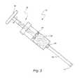
- FIG. 3illustrates an artificial bone injector
- FIG. 4illustrates the artificial bone injector coupled with the biologically active jacket
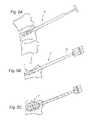
- FIGS. 5A-5Cillustrate the steps in the vertebral reconstruction.
- a preferred embodimentincludes a jacket 12 of synthetic bio-absorbable fiber network woven like cloth and may be uni-compartmental or multi-loculated. If multi-loculated the loculations 14 will have connecting valves 16 made of overlapping wall fibers acting as trap-doors that open up as the chamber is filled with artificial bone to allow filling of the neighboring chambers.
- the jacket 12has a central fenestrated channel 18 that runs through the length of the jacket 12 . The channel 18 is sealed at its far end, and the near end is threaded 20 to allow a cement injector to be screwed on.
- the multi-loculated designhas concentric chambers with the central channel 18 running down the center of the innermost chamber.
- Each chambermay be partially loculated to reinforce the construct with multiple networks of fibers to minimize the risk of compression fracture of the implant itself.
- the artificial boneis injected into the central channel 18 from which the cement extrudes into the inner-most chamber.
- the outer chambers 22will also have fenestrations in the outer wall to allow some artificial bone to extrude and anchor into the host bone.
- the entire jacket 12may be fitted with a network of channels extending into its interior from the outer wall. These channels will act as a conduit for vascular in-growth.
- the fiber network of the jacket 12may be used as a carrier for various factors by impregnating with a material suited for a particular purpose.
- the materialmay be bone morphogenic proteins to stimulate osteo-induction and osteosynthesis within the artificial bone, antibiotics as a prophylaxis against infection, or the like.
- the artificial bone 24( FIG. 3 ), in a preferred embodiment, is in a semi-liquid state which sets into a hard bone within a few minutes after injection into the implant jacket 12 in the vertebral body.
- a catalystmay also be impregnated into the walls of the jacket 12 to speed up the setting process.
- the ceramic bone (artificial bone) 24may be made out of hydroxyapatite or other calcium compounds.
- FIG. 2illustrates a drill and biopsy tool 26 for creating a cavity in the vertebra to be reconstructed and for taking a biopsy sample.
- the device 26includes a drill bit 28 at the tip, and immediately next to it is biopsy tool 30 for shaving of the host bone.
- the shaving tool 30is hollow in its center for collection of bone shavings. At the conclusion of the drilling, enough bone shavings will have been collected for a biopsy specimen.
- the diameter of the shaving tool 30is the same or slightly larger than the diameter of the unexpanded implant jacket 12 .
- the artificial bone injector 32is shown in FIGS. 3 and 4 .
- the injector 32includes a syringe with a plunger 34 that is operated by a screw mechanism 36 . As the handle 38 is turned clockwise, the plunger 34 goes deeper into the syringe and pushes out the artificial bone 24 .
- the nozzle 40 of the syringeis connected through a screw mechanism to an injection cannula 42 .
- the injection cannula 42in turn includes a threaded connector 44 or the like that is engageable with the threads 20 on the biologically active jacket 12 .
- the patientis placed on a radiolucent operating table in the prone or lateral position depending on the surgeon's preference.
- the skinis marked at the level of the target pedicles with the aid of fluoroscopic visualization.
- a trochar and cannulaare inserted under fluoroscopic visualization into the target pedicle.
- the positionis checked in antero-posterior, lateral and oblique projections.
- the trocharis then inserted deeper into the vertebra to establish the preferred trajectory.
- the cannula 42is then advanced until it is at least 3 mm deep to the posterior wall of the vertebra to be reconstructed. At this point, the trochar is removed leaving the cannula 42 in place.
- the drill/biopsy tool 26is inserted through the cannula, and hand drilling is performed by clockwise turning of the handle. See FIG. 5A . Drilling is carried out to within 5 millimeters of the anterior cortex. The drill/biopsy tool 26 is then removed.
- the unexpanded implant jacket 12is attached to the injection cannula 42 and is inserted through the cannula 42 to the appropriate depth as determined by fluoroscopically reading the position of the radio-opaque marker at the advancing tip of the device. See FIG. 5B .
- the injection cannula 42is attached to the syringe containing the artificial bone, and the artificial bone is injected while visualizing fluoroscopically. See FIG. 5C .
- Implant jacket1. Implant jacket:
- the structure and method described hereinprovide for effective biologic vertebral reconstruction.
- the use of a biological material and artificial boneenables the host bone to replace the artificial bone over a period of time. Additionally, the structure of the biologically active jacket minimizes any impact into the spinal canal and the paravertebral spaces. Moreover, because of its biomechanical characteristics, which approximate the host bone, there is relative protection of the neighboring vertebra against fracture. Still further, the materials of the biologically active jacket may be impregnated with various substances to achieve various advantageous tasks.
Landscapes
- Health & Medical Sciences (AREA)
- Orthopedic Medicine & Surgery (AREA)
- Life Sciences & Earth Sciences (AREA)
- Biomedical Technology (AREA)
- Engineering & Computer Science (AREA)
- General Health & Medical Sciences (AREA)
- Public Health (AREA)
- Veterinary Medicine (AREA)
- Animal Behavior & Ethology (AREA)
- Neurology (AREA)
- Transplantation (AREA)
- Heart & Thoracic Surgery (AREA)
- Surgery (AREA)
- Oral & Maxillofacial Surgery (AREA)
- Molecular Biology (AREA)
- Chemical & Material Sciences (AREA)
- Medicinal Chemistry (AREA)
- Cardiology (AREA)
- Vascular Medicine (AREA)
- Medical Informatics (AREA)
- Nuclear Medicine, Radiotherapy & Molecular Imaging (AREA)
- Dermatology (AREA)
- Epidemiology (AREA)
- Prostheses (AREA)
- Surgical Instruments (AREA)
Abstract
Description
- i. Single layer
- ii. Double layer wall
- iii. Uni-compartmental
- iv. Multi-compartmental
- v. Elastic
- vi. In-elastic, folded
- i. Create void and then implant
- ii. Implant to correct deformity as the artificial bone is injected
Claims (8)
Priority Applications (3)
| Application Number | Priority Date | Filing Date | Title |
|---|---|---|---|
| US12/018,507US8292961B2 (en) | 2008-01-23 | 2008-01-23 | Biologic vertebral reconstruction |
| US13/590,593US9023048B2 (en) | 2008-01-23 | 2012-08-21 | Biologic vertebral reconstruction |
| US14/664,371US9414929B2 (en) | 2008-01-23 | 2015-03-20 | Biologic vertebral reconstruction |
Applications Claiming Priority (1)
| Application Number | Priority Date | Filing Date | Title |
|---|---|---|---|
| US12/018,507US8292961B2 (en) | 2008-01-23 | 2008-01-23 | Biologic vertebral reconstruction |
Related Child Applications (1)
| Application Number | Title | Priority Date | Filing Date |
|---|---|---|---|
| US13/590,593DivisionUS9023048B2 (en) | 2008-01-23 | 2012-08-21 | Biologic vertebral reconstruction |
Publications (2)
| Publication Number | Publication Date |
|---|---|
| US20090187249A1 US20090187249A1 (en) | 2009-07-23 |
| US8292961B2true US8292961B2 (en) | 2012-10-23 |
Family
ID=40877069
Family Applications (3)
| Application Number | Title | Priority Date | Filing Date |
|---|---|---|---|
| US12/018,507Expired - Fee RelatedUS8292961B2 (en) | 2008-01-23 | 2008-01-23 | Biologic vertebral reconstruction |
| US13/590,593Expired - Fee RelatedUS9023048B2 (en) | 2008-01-23 | 2012-08-21 | Biologic vertebral reconstruction |
| US14/664,371Expired - Fee RelatedUS9414929B2 (en) | 2008-01-23 | 2015-03-20 | Biologic vertebral reconstruction |
Family Applications After (2)
| Application Number | Title | Priority Date | Filing Date |
|---|---|---|---|
| US13/590,593Expired - Fee RelatedUS9023048B2 (en) | 2008-01-23 | 2012-08-21 | Biologic vertebral reconstruction |
| US14/664,371Expired - Fee RelatedUS9414929B2 (en) | 2008-01-23 | 2015-03-20 | Biologic vertebral reconstruction |
Country Status (1)
| Country | Link |
|---|---|
| US (3) | US8292961B2 (en) |
Cited By (10)
| Publication number | Priority date | Publication date | Assignee | Title |
|---|---|---|---|---|
| US20130012946A1 (en)* | 2011-07-05 | 2013-01-10 | Johan Janssens | Combination of a bone drill and a sleeve |
| US20140180415A1 (en)* | 2012-12-26 | 2014-06-26 | Scott A. Koss | Apparatus, kit, and method for percutaneous intervertebral disc restoration |
| TWI495458B (en)* | 2012-11-13 | 2015-08-11 | Univ Chang Gung | A device that supports bone strength |
| US9545321B2 (en) | 2013-03-14 | 2017-01-17 | Spinal Stabilization Technologies Llc | Prosthetic spinal disk nucleus |
| US10314714B2 (en) | 2014-11-04 | 2019-06-11 | Spinal Stabilization Technologies Llc | Percutaneous implantable nuclear prosthesis |
| US10575967B2 (en) | 2015-09-01 | 2020-03-03 | Spinal Stabilization Technologies Llc | Implantable nuclear prosthesis |
| US11213402B2 (en) | 2017-01-11 | 2022-01-04 | Loubert S. Suddaby | Endoscopically implantable inflatable interbody fusion device |
| US11419733B2 (en) | 2018-01-12 | 2022-08-23 | Percheron Spine, Llc | Spinal disc implant and device and method for percutaneous delivery of the spinal disc implant |
| US11633287B2 (en) | 2014-11-04 | 2023-04-25 | Spinal Stabilization Technologies Llc | Percutaneous implantable nuclear prosthesis |
| US11744710B2 (en) | 2018-09-04 | 2023-09-05 | Spinal Stabilization Technologies Llc | Implantable nuclear prosthesis, kits, and related methods |
Families Citing this family (46)
| Publication number | Priority date | Publication date | Assignee | Title |
|---|---|---|---|---|
| US8323341B2 (en) | 2007-09-07 | 2012-12-04 | Intrinsic Therapeutics, Inc. | Impaction grafting for vertebral fusion |
| US7094258B2 (en) | 1999-08-18 | 2006-08-22 | Intrinsic Therapeutics, Inc. | Methods of reinforcing an annulus fibrosis |
| US7972337B2 (en) | 2005-12-28 | 2011-07-05 | Intrinsic Therapeutics, Inc. | Devices and methods for bone anchoring |
| US7717961B2 (en) | 1999-08-18 | 2010-05-18 | Intrinsic Therapeutics, Inc. | Apparatus delivery in an intervertebral disc |
| EP1624832A4 (en) | 1999-08-18 | 2008-12-24 | Intrinsic Therapeutics Inc | Devices and method for augmenting a vertebral disc nucleus |
| US7998213B2 (en) | 1999-08-18 | 2011-08-16 | Intrinsic Therapeutics, Inc. | Intervertebral disc herniation repair |
| CA2425951C (en) | 1999-08-18 | 2008-09-16 | Intrinsic Therapeutics, Inc. | Devices and method for nucleus pulposus augmentation and retention |
| US20030055316A1 (en)* | 2001-09-19 | 2003-03-20 | Brannon James Kevin | Endoscopic bone debridement |
| CN100584294C (en)* | 2002-08-27 | 2010-01-27 | 华沙整形外科股份有限公司 | System for intravertebral reduction |
| WO2006058221A2 (en) | 2004-11-24 | 2006-06-01 | Abdou Samy M | Devices and methods for inter-vertebral orthopedic device placement |
| US7955339B2 (en)* | 2005-05-24 | 2011-06-07 | Kyphon Sarl | Low-compliance expandable medical device |
| US20070042326A1 (en)* | 2005-06-01 | 2007-02-22 | Osseous Technologies Of America | Collagen antral membrane expander |
| US7988735B2 (en)* | 2005-06-15 | 2011-08-02 | Matthew Yurek | Mechanical apparatus and method for delivering materials into the inter-vertebral body space for nucleus replacement |
| US20110196492A1 (en) | 2007-09-07 | 2011-08-11 | Intrinsic Therapeutics, Inc. | Bone anchoring systems |
| WO2010093955A1 (en)* | 2009-02-12 | 2010-08-19 | Osteotech,Inc. | Segmented delivery system |
| US8764806B2 (en) | 2009-12-07 | 2014-07-01 | Samy Abdou | Devices and methods for minimally invasive spinal stabilization and instrumentation |
| US9358058B2 (en) | 2012-11-05 | 2016-06-07 | Globus Medical, Inc. | Methods and apparatus for treating vertebral fractures |
| US9326799B2 (en) | 2009-12-07 | 2016-05-03 | Globus Medical, Inc. | Methods and apparatus for treating vertebral fractures |
| US11090092B2 (en) | 2009-12-07 | 2021-08-17 | Globus Medical Inc. | Methods and apparatus for treating vertebral fractures |
| US9526538B2 (en) | 2009-12-07 | 2016-12-27 | Globus Medical, Inc. | Methods and apparatus for treating vertebral fractures |
| US8734458B2 (en)* | 2009-12-07 | 2014-05-27 | Globus Medical, Inc. | Methods and apparatus for treating vertebral fractures |
| US9220554B2 (en)* | 2010-02-18 | 2015-12-29 | Globus Medical, Inc. | Methods and apparatus for treating vertebral fractures |
| US20120130489A1 (en)* | 2010-05-19 | 2012-05-24 | Chernomorsky Ary S | Methods and apparatus for in situ formation of surgical implants |
| EP2685921B1 (en)* | 2011-03-18 | 2019-03-13 | Raed M. Ali, M.D., Inc. | Transpedicular access to intervertebral spaces and related spinal fusion systems and methods |
| US9265620B2 (en) | 2011-03-18 | 2016-02-23 | Raed M. Ali, M.D., Inc. | Devices and methods for transpedicular stabilization of the spine |
| DE102011108010A1 (en)* | 2011-07-20 | 2013-01-24 | Heraeus Medical Gmbh | Applicator Kit |
| US8845728B1 (en) | 2011-09-23 | 2014-09-30 | Samy Abdou | Spinal fixation devices and methods of use |
| US20130226240A1 (en) | 2012-02-22 | 2013-08-29 | Samy Abdou | Spinous process fixation devices and methods of use |
| US9198767B2 (en) | 2012-08-28 | 2015-12-01 | Samy Abdou | Devices and methods for spinal stabilization and instrumentation |
| US9320617B2 (en) | 2012-10-22 | 2016-04-26 | Cogent Spine, LLC | Devices and methods for spinal stabilization and instrumentation |
| US9907654B2 (en)* | 2012-12-11 | 2018-03-06 | Dr. H.C. Robert Mathys Stiftung | Bone substitute and method for producing the same |
| US9861495B2 (en) | 2013-03-14 | 2018-01-09 | Raed M. Ali, M.D., Inc. | Lateral interbody fusion devices, systems and methods |
| US10687962B2 (en) | 2013-03-14 | 2020-06-23 | Raed M. Ali, M.D., Inc. | Interbody fusion devices, systems and methods |
| US10420597B2 (en)* | 2014-12-16 | 2019-09-24 | Arthrex, Inc. | Surgical implant with porous region |
| US10857003B1 (en) | 2015-10-14 | 2020-12-08 | Samy Abdou | Devices and methods for vertebral stabilization |
| US10070902B2 (en)* | 2016-04-05 | 2018-09-11 | Warsaw Orthopedic, Inc. | Spinal implant system and method |
| WO2017192632A1 (en) | 2016-05-03 | 2017-11-09 | Additive Orthopaedics, LLC | Bone fixation device and method of use |
| WO2017210695A1 (en) | 2016-06-03 | 2017-12-07 | Additive Orthopaedics, LLC | Bone fixation devices |
| US11058468B2 (en) | 2016-07-29 | 2021-07-13 | Additive Orthopaedics, LLC | Bone fixation device and method of use |
| US10973648B1 (en) | 2016-10-25 | 2021-04-13 | Samy Abdou | Devices and methods for vertebral bone realignment |
| US10744000B1 (en) | 2016-10-25 | 2020-08-18 | Samy Abdou | Devices and methods for vertebral bone realignment |
| US11452548B2 (en) | 2017-04-21 | 2022-09-27 | Stryker Corporation | Stabilization system, implant, and methods for preventing relative motion between sections of tissue |
| US11147679B2 (en) | 2018-02-05 | 2021-10-19 | Paragon Advanced Technologies, Inc. | Bone fixation device |
| US11179248B2 (en) | 2018-10-02 | 2021-11-23 | Samy Abdou | Devices and methods for spinal implantation |
| US11318026B2 (en)* | 2020-07-24 | 2022-05-03 | Synaptic Innovations, LLC | Implant having enhanced initial fixation force |
| US11298238B1 (en)* | 2021-07-23 | 2022-04-12 | Focus Medical Company, Llc | Balloon kyphoplasty surgical device and method |
Citations (5)
| Publication number | Priority date | Publication date | Assignee | Title |
|---|---|---|---|---|
| US20020147497A1 (en)* | 2001-04-06 | 2002-10-10 | Integrated Vascular Systems, Inc. | Methods for treating spinal discs |
| US20030199984A1 (en)* | 2000-08-30 | 2003-10-23 | Trieu Hai H. | Intervertebral disc nucleus implants and methods |
| US20040210231A1 (en)* | 1998-08-14 | 2004-10-21 | Kyphon Inc. | Systems and methods for treating vertebral bodies |
| US20050261781A1 (en)* | 2004-04-15 | 2005-11-24 | Sennett Andrew R | Cement-directing orthopedic implants |
| US20090105823A1 (en)* | 2004-09-30 | 2009-04-23 | Synecor, Llc | Artificial intervertebral disc nucleus |
Family Cites Families (6)
| Publication number | Priority date | Publication date | Assignee | Title |
|---|---|---|---|---|
| US5015247A (en)* | 1988-06-13 | 1991-05-14 | Michelson Gary K | Threaded spinal implant |
| US5571189A (en)* | 1994-05-20 | 1996-11-05 | Kuslich; Stephen D. | Expandable fabric implant for stabilizing the spinal motion segment |
| US5556399A (en)* | 1995-02-14 | 1996-09-17 | Huebner; Randall J. | Bone-harvesting drill apparatus and method for its use |
| US6827743B2 (en)* | 2001-02-28 | 2004-12-07 | Sdgi Holdings, Inc. | Woven orthopedic implants |
| JP2006513760A (en)* | 2003-02-13 | 2006-04-27 | ジンテーズ アクチエンゲゼルシャフト クール | Injectable bone replacement compound |
| US20080103505A1 (en)* | 2006-10-26 | 2008-05-01 | Hendrik Raoul Andre Fransen | Containment device for site-specific delivery of a therapeutic material and methods of use |
- 2008
- 2008-01-23USUS12/018,507patent/US8292961B2/ennot_activeExpired - Fee Related
- 2012
- 2012-08-21USUS13/590,593patent/US9023048B2/ennot_activeExpired - Fee Related
- 2015
- 2015-03-20USUS14/664,371patent/US9414929B2/ennot_activeExpired - Fee Related
Patent Citations (5)
| Publication number | Priority date | Publication date | Assignee | Title |
|---|---|---|---|---|
| US20040210231A1 (en)* | 1998-08-14 | 2004-10-21 | Kyphon Inc. | Systems and methods for treating vertebral bodies |
| US20030199984A1 (en)* | 2000-08-30 | 2003-10-23 | Trieu Hai H. | Intervertebral disc nucleus implants and methods |
| US20020147497A1 (en)* | 2001-04-06 | 2002-10-10 | Integrated Vascular Systems, Inc. | Methods for treating spinal discs |
| US20050261781A1 (en)* | 2004-04-15 | 2005-11-24 | Sennett Andrew R | Cement-directing orthopedic implants |
| US20090105823A1 (en)* | 2004-09-30 | 2009-04-23 | Synecor, Llc | Artificial intervertebral disc nucleus |
Cited By (18)
| Publication number | Priority date | Publication date | Assignee | Title |
|---|---|---|---|---|
| US9237906B2 (en)* | 2011-07-05 | 2016-01-19 | Johan Janssens | Combination of a bone drill and a sleeve |
| US20130012946A1 (en)* | 2011-07-05 | 2013-01-10 | Johan Janssens | Combination of a bone drill and a sleeve |
| TWI495458B (en)* | 2012-11-13 | 2015-08-11 | Univ Chang Gung | A device that supports bone strength |
| US20140180415A1 (en)* | 2012-12-26 | 2014-06-26 | Scott A. Koss | Apparatus, kit, and method for percutaneous intervertebral disc restoration |
| US10285818B2 (en)* | 2012-12-26 | 2019-05-14 | Symbiomedik, Llc | Apparatus, kit, and method for percutaneous intervertebral disc restoration |
| US11406513B2 (en) | 2013-03-14 | 2022-08-09 | Spinal Stabilization Technologies, Llc | Prosthetic spinal disk nucleus |
| US9545321B2 (en) | 2013-03-14 | 2017-01-17 | Spinal Stabilization Technologies Llc | Prosthetic spinal disk nucleus |
| US11633287B2 (en) | 2014-11-04 | 2023-04-25 | Spinal Stabilization Technologies Llc | Percutaneous implantable nuclear prosthesis |
| US10314714B2 (en) | 2014-11-04 | 2019-06-11 | Spinal Stabilization Technologies Llc | Percutaneous implantable nuclear prosthesis |
| US11638649B2 (en) | 2014-11-04 | 2023-05-02 | Spinal Stabilization Technologies Llc | Percutaneous implantable nuclear prosthesis |
| US12279963B2 (en) | 2014-11-04 | 2025-04-22 | Spinal Stabilization Technologies Llc | Percutaneous implantable nuclear prosthesis |
| US10575967B2 (en) | 2015-09-01 | 2020-03-03 | Spinal Stabilization Technologies Llc | Implantable nuclear prosthesis |
| US11576793B2 (en) | 2015-09-01 | 2023-02-14 | Spinal Stabilization Technologies Llc | Implantable nuclear prosthesis |
| US11213402B2 (en) | 2017-01-11 | 2022-01-04 | Loubert S. Suddaby | Endoscopically implantable inflatable interbody fusion device |
| US11419733B2 (en) | 2018-01-12 | 2022-08-23 | Percheron Spine, Llc | Spinal disc implant and device and method for percutaneous delivery of the spinal disc implant |
| US11957597B2 (en) | 2018-01-12 | 2024-04-16 | Percheron Spine, Llc | Spinal disc implant and device and method for percutaneous delivery of the spinal disc implant |
| US12318303B2 (en) | 2018-01-12 | 2025-06-03 | Percheron Spine, Llc | Spinal disc implant and device and method for percutaneous delivery of the spinal disc implant |
| US11744710B2 (en) | 2018-09-04 | 2023-09-05 | Spinal Stabilization Technologies Llc | Implantable nuclear prosthesis, kits, and related methods |
Also Published As
| Publication number | Publication date |
|---|---|
| US20090187249A1 (en) | 2009-07-23 |
| US20150190239A1 (en) | 2015-07-09 |
| US9023048B2 (en) | 2015-05-05 |
| US20120316566A1 (en) | 2012-12-13 |
| US9414929B2 (en) | 2016-08-16 |
Similar Documents
| Publication | Publication Date | Title |
|---|---|---|
| US9414929B2 (en) | Biologic vertebral reconstruction | |
| US6730095B2 (en) | Retrograde plunger delivery system | |
| JP5159320B2 (en) | 3D implantable bone support | |
| US11771485B2 (en) | Device for performing a surgical procedure and method | |
| US9439702B2 (en) | Bone fracture reduction system and methods of using the same | |
| EP1578315B1 (en) | Apparatus for spinal distraction and fusion | |
| US6899716B2 (en) | Method and apparatus for spinal augmentation | |
| US20070055257A1 (en) | Cannulated screw access system | |
| US11883296B2 (en) | Process of bone creation between adjacent vertebrae | |
| JP2004516855A (en) | Spine treatment device | |
| EP1646333A1 (en) | Biocompatible wires and systems employing same to fill bone void | |
| EP3203941B1 (en) | Bone scaffold improvements | |
| US9204915B2 (en) | Device for performing a surgical procedure and method | |
| WO2007029998A2 (en) | Repair of bone defects |
Legal Events
| Date | Code | Title | Description |
|---|---|---|---|
| ZAAA | Notice of allowance and fees due | Free format text:ORIGINAL CODE: NOA | |
| ZAAB | Notice of allowance mailed | Free format text:ORIGINAL CODE: MN/=. | |
| STCF | Information on status: patent grant | Free format text:PATENTED CASE | |
| AS | Assignment | Owner name:AMENDIA, INC., GEORGIA Free format text:ASSIGNMENT OF ASSIGNORS INTEREST;ASSIGNOR:OSMAN, SAID G.;REEL/FRAME:034865/0151 Effective date:20150126 | |
| AS | Assignment | Owner name:ANTARES CAPITAL LP, AS AGENT, ILLINOIS Free format text:SECURITY INTEREST;ASSIGNOR:AMENDIA, INC.;REEL/FRAME:038587/0753 Effective date:20160429 | |
| FPAY | Fee payment | Year of fee payment:4 | |
| SULP | Surcharge for late payment | ||
| AS | Assignment | Owner name:CORTLAND CAPITAL MARKET SERVICES LLC, AS AGENT, IL Free format text:SECURITY INTEREST;ASSIGNOR:AMENDIA, INC.;REEL/FRAME:038606/0520 Effective date:20160429 | |
| AS | Assignment | Owner name:SPINAL ELEMENTS, INC., CALIFORNIA Free format text:MERGER AND CHANGE OF NAME;ASSIGNORS:SPINAL ELEMENTS, INC.;AMENDIA, INC.;REEL/FRAME:052024/0805 Effective date:20191231 | |
| FEPP | Fee payment procedure | Free format text:MAINTENANCE FEE REMINDER MAILED (ORIGINAL EVENT CODE: REM.); ENTITY STATUS OF PATENT OWNER: SMALL ENTITY | |
| FEPP | Fee payment procedure | Free format text:7.5 YR SURCHARGE - LATE PMT W/IN 6 MO, SMALL ENTITY (ORIGINAL EVENT CODE: M2555); ENTITY STATUS OF PATENT OWNER: SMALL ENTITY | |
| MAFP | Maintenance fee payment | Free format text:PAYMENT OF MAINTENANCE FEE, 8TH YR, SMALL ENTITY (ORIGINAL EVENT CODE: M2552); ENTITY STATUS OF PATENT OWNER: SMALL ENTITY Year of fee payment:8 | |
| AS | Assignment | Owner name:PERCEPTIVE CREDIT HOLDINGS IV, LP, NEW YORK Free format text:SECURITY INTEREST;ASSIGNORS:SPINAL ELEMENTS, INC.;CUSTOM SPINE ACQUISITION, INC.;OMNI ACQUISITION INC.;REEL/FRAME:067596/0295 Effective date:20240531 | |
| AS | Assignment | Owner name:SPINAL ELEMENTS, INC. (F.K.A. AMENDIA, INC.), CALIFORNIA Free format text:RELEASE BY SECURED PARTY;ASSIGNOR:CORTLAND CAPITAL MARKET SERVICES LLC, AS AGENT;REEL/FRAME:067605/0676 Effective date:20240531 Owner name:SPINAL ELEMENTS, INC. (F.K.A. AMENDIA, INC.), CALIFORNIA Free format text:RELEASE BY SECURED PARTY;ASSIGNOR:ANTARES CAPITAL LP, AS ADMINISTRATIVE AGENT;REEL/FRAME:067605/0599 Effective date:20240531 | |
| FEPP | Fee payment procedure | Free format text:MAINTENANCE FEE REMINDER MAILED (ORIGINAL EVENT CODE: REM.); ENTITY STATUS OF PATENT OWNER: SMALL ENTITY | |
| LAPS | Lapse for failure to pay maintenance fees | Free format text:PATENT EXPIRED FOR FAILURE TO PAY MAINTENANCE FEES (ORIGINAL EVENT CODE: EXP.); ENTITY STATUS OF PATENT OWNER: SMALL ENTITY | |
| STCH | Information on status: patent discontinuation | Free format text:PATENT EXPIRED DUE TO NONPAYMENT OF MAINTENANCE FEES UNDER 37 CFR 1.362 | |
| FP | Lapsed due to failure to pay maintenance fee | Effective date:20241023 |