US8292929B2 - Dynamic spinal stabilization system and method of using the same - Google Patents
Dynamic spinal stabilization system and method of using the sameDownload PDFInfo
- Publication number
- US8292929B2 US8292929B2US11/687,014US68701407AUS8292929B2US 8292929 B2US8292929 B2US 8292929B2US 68701407 AUS68701407 AUS 68701407AUS 8292929 B2US8292929 B2US 8292929B2
- Authority
- US
- United States
- Prior art keywords
- body portion
- connector
- connectors
- spacer
- anchor
- Prior art date
- Legal status (The legal status is an assumption and is not a legal conclusion. Google has not performed a legal analysis and makes no representation as to the accuracy of the status listed.)
- Active, expires
Links
- 230000006641stabilisationEffects0.000titleclaimsabstractdescription70
- 238000011105stabilizationMethods0.000titleclaimsabstractdescription70
- 238000000034methodMethods0.000titleclaimsabstractdescription17
- 125000006850spacer groupChemical group0.000claimsabstractdescription65
- 210000000988bone and boneAnatomy0.000claimsabstractdescription31
- 230000008878couplingEffects0.000claimsabstractdescription12
- 238000010168coupling processMethods0.000claimsabstractdescription12
- 238000005859coupling reactionMethods0.000claimsabstractdescription12
- 230000000087stabilizing effectEffects0.000claimsabstractdescription6
- 230000033001locomotionEffects0.000claimsdescription12
- 230000002708enhancing effectEffects0.000claims2
- 239000000463materialSubstances0.000description8
- 230000005540biological transmissionEffects0.000description6
- 230000004927fusionEffects0.000description6
- RTAQQCXQSZGOHL-UHFFFAOYSA-NTitaniumChemical compound[Ti]RTAQQCXQSZGOHL-UHFFFAOYSA-N0.000description4
- 230000002159abnormal effectEffects0.000description4
- 230000008901benefitEffects0.000description4
- 238000013461designMethods0.000description4
- 239000010936titaniumSubstances0.000description4
- 229910052719titaniumInorganic materials0.000description4
- 208000037265diseases, disorders, signs and symptomsDiseases0.000description3
- 230000000694effectsEffects0.000description3
- 238000011065in-situ storageMethods0.000description3
- 238000003780insertionMethods0.000description3
- 230000037431insertionEffects0.000description3
- 230000009467reductionEffects0.000description3
- 238000001356surgical procedureMethods0.000description3
- 238000005452bendingMethods0.000description2
- 238000010276constructionMethods0.000description2
- 208000035475disorderDiseases0.000description2
- 238000006073displacement reactionMethods0.000description2
- 208000014674injuryDiseases0.000description2
- 230000035479physiological effects, processes and functionsEffects0.000description2
- 229920001692polycarbonate urethanePolymers0.000description2
- 229920000139polyethylene terephthalatePolymers0.000description2
- 239000005020polyethylene terephthalateSubstances0.000description2
- 210000000278spinal cordAnatomy0.000description2
- 210000001032spinal nerveAnatomy0.000description2
- 229910001220stainless steelInorganic materials0.000description2
- 239000010935stainless steelSubstances0.000description2
- 210000000115thoracic cavityAnatomy0.000description2
- 208000003618Intervertebral Disc DisplacementDiseases0.000description1
- 206010061246Intervertebral disc degenerationDiseases0.000description1
- 206010023509KyphosisDiseases0.000description1
- 208000007623LordosisDiseases0.000description1
- 208000020307Spinal diseaseDiseases0.000description1
- 208000007103SpondylolisthesisDiseases0.000description1
- 208000027418Wounds and injuryDiseases0.000description1
- 230000005856abnormalityEffects0.000description1
- 230000001154acute effectEffects0.000description1
- 239000000853adhesiveSubstances0.000description1
- 230000001070adhesive effectEffects0.000description1
- 208000037873arthrodesisDiseases0.000description1
- 230000001684chronic effectEffects0.000description1
- 210000002808connective tissueAnatomy0.000description1
- 230000001054cortical effectEffects0.000description1
- 230000006378damageEffects0.000description1
- 230000007423decreaseEffects0.000description1
- 230000007850degenerationEffects0.000description1
- 208000018180degenerative disc diseaseDiseases0.000description1
- 230000003292diminished effectEffects0.000description1
- 201000010099diseaseDiseases0.000description1
- 238000002513implantationMethods0.000description1
- 238000009434installationMethods0.000description1
- 208000021600intervertebral disc degenerative diseaseDiseases0.000description1
- 230000002427irreversible effectEffects0.000description1
- 210000004705lumbosacral regionAnatomy0.000description1
- 230000013011matingEffects0.000description1
- 230000007246mechanismEffects0.000description1
- 239000007769metal materialSubstances0.000description1
- 238000012986modificationMethods0.000description1
- 230000004048modificationEffects0.000description1
- 210000003205muscleAnatomy0.000description1
- 210000005036nerveAnatomy0.000description1
- 210000000653nervous systemAnatomy0.000description1
- 230000007170pathologyEffects0.000description1
- -1polyethylene terephthalatePolymers0.000description1
- 238000011084recoveryMethods0.000description1
- 238000012552reviewMethods0.000description1
- 206010039722scoliosisDiseases0.000description1
- 206010041569spinal fractureDiseases0.000description1
- 238000011477surgical interventionMethods0.000description1
- 210000001519tissueAnatomy0.000description1
- 238000012546transferMethods0.000description1
- 230000008733traumaEffects0.000description1
Images


Classifications
- A—HUMAN NECESSITIES
- A61—MEDICAL OR VETERINARY SCIENCE; HYGIENE
- A61B—DIAGNOSIS; SURGERY; IDENTIFICATION
- A61B17/00—Surgical instruments, devices or methods
- A61B17/56—Surgical instruments or methods for treatment of bones or joints; Devices specially adapted therefor
- A61B17/58—Surgical instruments or methods for treatment of bones or joints; Devices specially adapted therefor for osteosynthesis, e.g. bone plates, screws or setting implements
- A61B17/68—Internal fixation devices, including fasteners and spinal fixators, even if a part thereof projects from the skin
- A61B17/70—Spinal positioners or stabilisers, e.g. stabilisers comprising fluid filler in an implant
- A61B17/7001—Screws or hooks combined with longitudinal elements which do not contact vertebrae
- A61B17/7032—Screws or hooks with U-shaped head or back through which longitudinal rods pass
- A—HUMAN NECESSITIES
- A61—MEDICAL OR VETERINARY SCIENCE; HYGIENE
- A61B—DIAGNOSIS; SURGERY; IDENTIFICATION
- A61B17/00—Surgical instruments, devices or methods
- A61B17/56—Surgical instruments or methods for treatment of bones or joints; Devices specially adapted therefor
- A61B17/58—Surgical instruments or methods for treatment of bones or joints; Devices specially adapted therefor for osteosynthesis, e.g. bone plates, screws or setting implements
- A61B17/68—Internal fixation devices, including fasteners and spinal fixators, even if a part thereof projects from the skin
- A61B17/70—Spinal positioners or stabilisers, e.g. stabilisers comprising fluid filler in an implant
- A61B17/7001—Screws or hooks combined with longitudinal elements which do not contact vertebrae
- A61B17/7002—Longitudinal elements, e.g. rods
- A61B17/7004—Longitudinal elements, e.g. rods with a cross-section which varies along its length
- A61B17/7008—Longitudinal elements, e.g. rods with a cross-section which varies along its length with parts of, or attached to, the longitudinal elements, bearing against an outside of the screw or hook heads, e.g. nuts on threaded rods
- A—HUMAN NECESSITIES
- A61—MEDICAL OR VETERINARY SCIENCE; HYGIENE
- A61B—DIAGNOSIS; SURGERY; IDENTIFICATION
- A61B17/00—Surgical instruments, devices or methods
- A61B17/56—Surgical instruments or methods for treatment of bones or joints; Devices specially adapted therefor
- A61B17/58—Surgical instruments or methods for treatment of bones or joints; Devices specially adapted therefor for osteosynthesis, e.g. bone plates, screws or setting implements
- A61B17/68—Internal fixation devices, including fasteners and spinal fixators, even if a part thereof projects from the skin
- A61B17/70—Spinal positioners or stabilisers, e.g. stabilisers comprising fluid filler in an implant
- A61B17/7001—Screws or hooks combined with longitudinal elements which do not contact vertebrae
- A61B17/7002—Longitudinal elements, e.g. rods
- A61B17/7019—Longitudinal elements having flexible parts, or parts connected together, such that after implantation the elements can move relative to each other
- A61B17/7031—Longitudinal elements having flexible parts, or parts connected together, such that after implantation the elements can move relative to each other made wholly or partly of flexible material
- A—HUMAN NECESSITIES
- A61—MEDICAL OR VETERINARY SCIENCE; HYGIENE
- A61B—DIAGNOSIS; SURGERY; IDENTIFICATION
- A61B17/00—Surgical instruments, devices or methods
- A61B17/56—Surgical instruments or methods for treatment of bones or joints; Devices specially adapted therefor
- A61B17/58—Surgical instruments or methods for treatment of bones or joints; Devices specially adapted therefor for osteosynthesis, e.g. bone plates, screws or setting implements
- A61B17/68—Internal fixation devices, including fasteners and spinal fixators, even if a part thereof projects from the skin
- A61B17/70—Spinal positioners or stabilisers, e.g. stabilisers comprising fluid filler in an implant
- A61B17/7001—Screws or hooks combined with longitudinal elements which do not contact vertebrae
- A61B17/7002—Longitudinal elements, e.g. rods
- A61B17/701—Longitudinal elements with a non-circular, e.g. rectangular, cross-section
Definitions
- the present inventiongenerally relates to spinal support devices, and more particularly to an apparatus and method for dynamically stabilizing the spine.
- the spinal columnis a highly complex system of bones and connective tissues that provides support for the body and protects the delicate spinal cord and nerves.
- the spinal columnincludes a series of vertebrae stacked one on top of the other, each vertebral body including a portion of relatively weak cancellous bone and a portion of relatively strong cortical bone. Situated between each vertebral body is an intervertebral disc that cushions and dampens compressive forces experienced by the spinal column.
- a vertebral canal containing the spinal cord and nervesis located posterior to the vertebral bodies.
- the spineis a highly flexible structure, capable of a high degree of curvature and twist in nearly every direction.
- the kinematics of the spinenormally includes flexion, extension, rotation and lateral bending.
- spinal column disordersincluding scoliosis (abnormal lateral curvature of the spine), kyphosis (abnormal forward curvature of the spine, usually in the thoracic spine), excess lordosis (abnormal backward curvature of the spine, usually in the lumbar spine), spondylolisthesis (forward displacement of one vertebra over another, usually in the lumbar or cervical spine), and other disorders caused by abnormalities, disease, or trauma, such as ruptured or slipped discs, degenerative disc disease, fractured vertebra, and the like. Patients that suffer from such conditions usually experience extreme and debilitating pain, as well as diminished nerve function.
- spinal disorders, pathologies, and injurieslimit the spine's range of motion, or threaten the critical elements of the nervous system housed within the spinal column.
- the treatment of acute and chronic spinal instabilities or deformities of the thoracic, lumbar, and sacral spinehas traditionally involved rigid stabilization.
- arthrodesis, or spine fusionis one of the most common surgical interventions today.
- the purpose of fusion or rigid stabilizationis the immobilization of a portion of the spine to affect treatment.
- Rigid stabilizationtypically includes implantation of a rigid assembly having metallic rods, plates and the like that secure selective vertebrae relative to each other.
- Spinal treatment using rigid stabilizationdoes have some disadvantages. For example, it has been shown that spine fusion decreases function by limiting the range of motion for patients in flexion, extension, rotation and lateral bending. Furthermore, it has been shown that spine fusion creates increased stresses and therefore, accelerated degeneration of adjacent non-fused segments. Another disadvantage of fusion is that it is an irreversible procedure.
- Dynamic stabilizationdoes not result in complete spinal fusion but instead permits enhanced mobility of the spine while also providing sufficient stabilization to effect treatment.
- a dynamic stabilization systemis the Dynesys® system available from Zimmer Spine, Inc. of Edina, Minn.
- Such dynamic stabilization systemstypically include a flexible spacer positioned between pedicle screws installed in adjacent vertebrae of the spine. Once the spacer is positioned between the pedicle screws, a flexible cord is threaded through eyelets formed in the pedicle screws and a channel through the spacer. The flexible cord retains the spacer between the pedicle screws while cooperating with the spacer to permit mobility of the spine.
- the contact between the ends of the spacer and the surfaces of the eyeletsoccurs at less than the full contact area results, then such a reduction in contact area between the components localizes the load transfer. This may be due to the specific vertebral physiology to which the stabilization system is being applied, the geometry of the components or the non-idealized placement of the anchors in the vertebrae. In any event, the resulting reduction in contact area between the spacer and anchors may diminish the capacity of the stabilization system to efficiently transmit applied loads to the vertebrae to which the anchors are attached. This may result in a reduction in the support provided by the stabilization system, a loss of the pre-tensioning of the system, or otherwise affect the stabilization system in a manner that impacts treatment of the spine.
- a dynamic stabilization systemthat provides improvements over existing stabilization systems includes at least two vertebral anchors having a bone attachment portion and a head portion.
- the vertebral anchorsmight be, for example, bone screws.
- Each of the vertebral anchorsis adapted to be coupled to different vertebrae of the spine.
- a flexible assemblyis removably coupled to the vertebral anchors and includes a flexible cord, at least two connectors slidably mounted to the flexible cord, and at least one spacer slidably mounted to the cord.
- Each of the connectorsis adapted to be coupled with a head portion of a respective anchor.
- the flexible assemblyis configured such that each spacer is disposed between adjacent connectors.
- the spatial relationship of the connectors on the flexible assemblyare capable of being fixed relative to the cord prior to the flexible assembly being coupled to the vertebral anchors.
- This aspectmay allow, for example, the flexible assembly to be assembled outside the body of a patient and then subsequently coupled to the anchors in situ.
- each of the connectorsincludes a channel extending through the connector for receiving the cord therein.
- Each connectorfurther includes a threaded bore extending from a surface of the connector and intersecting the channel.
- a set screwis threadably engaged with the bore and cooperates therewith so as to prevent relative movement between the cord and connector when the connector is mounted on the cord.
- the stabilization systemincludes at least two vertebral anchors having a bone attachment portion generally defining an axis, wherein each of the anchors is adapted to be coupled to different vertebrae of the spine.
- a flexible cordextends between the anchors.
- the systemfurther includes at least two connectors, each connector adapted to be coupled to the bone attachment portion of one of the vertebral anchors and to the flexible cord.
- a first spaceris disposed between adjacent connectors and includes a channel for receiving the cord therethrough.
- the first spacerincludes first and second opposed end faces.
- At least one of the connectorsincludes a first outer surface that confronts the first end face of the first spacer.
- the first outer surface of the at least one connectorforms an angle with respect to the axis of the bone attachment portion of the vertebral anchor. Angulation of the first outer surface enhances the contact area between the first outer surface of the at least one connector and the first end face of the first spacer. This aspect may allow, for example, improved transmission of loads through the stabilization system and to the vertebrae to which the system is attached.
- the at least one connectorincludes a lower surface and an upper surface, and the first outer surface is angled inwardly toward the axis of the bone attachment portion in a direction from the lower surface toward the upper surface. In another embodiment, however, the first outer surface is angled outwardly away from the axis of the bone attachment portion in a direction from the lower surface toward the upper surface.
- the at least one connectorincludes a second outer surface that confronts an end face of a second spacer. The second outer surface likewise forms an angle with respect to the axis of the bone attachment portion so as to enhance the contact area between the second outer surface and the end face of the second spacer.
- the angulation of the first and second outer surfacesmay be the same or may be different from each other.
- a spinal stabilization systemin yet another embodiment, includes a vertebral anchor having a bone attachment portion and a head portion.
- the anchoris adapted to be coupled to a vertebra of the spine.
- the head portionincludes a base member coupled to the bone attachment portion at one end thereof and a pair of spaced apart legs extending from the base member. The base member and legs collectively define an open channel in the head portion.
- the stabilization systemfurther includes an assembly having a connector for removably coupling the assembly to the anchor.
- the connectorincludes first and second body portions and a narrowed intermediate body portion extending between the first and second body portions. The first, second and intermediate body portions collectively define a pair of opposed cutouts that receive the legs of the head portion therein when the connector is coupled to the anchor. When the connector is so coupled to the anchor, the intermediate body portion is received in the open channel of the head portion.
- each of the legsprojects from the base member at an angle of approximately 90 degrees.
- the intermediate body portionmay likewise be configured so as to be closely received in the open channel. Accordingly, a pair of side surfaces of the intermediate body portion may project from a lower surface thereof at an angle of approximately 90 degrees.
- the open channel and intermediate body portionmay have a converging configuration to provided a snap-fit feature between the two.
- each of the legsprojects from the base member at an angle between approximately 85 degrees and 90 degrees.
- the side surfaces of the intermediate body portionmay project from the lower surface thereof at an angle between approximately 85 degrees and 90 degrees.
- the stabilization systemmay include a retaining mechanism for selectively retaining the connector with the anchor.
- the systemmay include a retaining clip that is applied to the ends of the legs opposite the base member.
- Each of the legsmay include a retaining notch that receives a portion of the retaining clip therein.
- a method of stabilizing a spine within a body of a patientincludes securing at least first and second anchors to respective first and second vertebrae of the spine, assembling a flexible assembly outside the body, adjusting the flexible assembly outside the body such that the flexible assembly is capable of stabilizing the spine once disposed inside the body, and removably coupling the flexible assembly to the anchors to stabilize the spine.
- assembling the flexible assemblymay include slidably mounting at least two connectors onto a flexible cord and/or slidably mounting at least one spacer on the cord so as to be positioned between the connectors.
- adjusting the flexible assemblymay include pre-tensioning the flexible cord, spatially fixing the connectors relative to the cord, and/or adjusting the length of the spacer.
- a method of stabilizing the spine in accordance with an alternate embodiment of the inventionincludes securing at least first and second anchors to respective first and second vertebrae of the spine, and providing a plethora of connectors for coupling a flexible assembly to the anchors.
- the flexible assemblyincludes at least one spacer with first and second opposed end faces.
- the connectorhas at least a first outer surface that forms an angle with respect to an axis of the anchor when coupled thereto.
- the methodfurther includes determining the angle of the first outer surface so that the first outer surface engages substantially all of one of the end faces of the spacer when the flexible assembly is coupled to the spine; constructing the flexible assembly using a connector having a first outer surface with the determined angle; and then coupling the flexible assembly to the anchors to stabilize the spine.
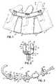
- FIG. 1is a side elevation view of an exemplary stabilization system in accordance with an embodiment of the invention implanted on the spine;
- FIG. 2is a front view of a bone anchor in accordance with an embodiment of the invention.
- FIG. 3is a perspective view of a flexible assembly in accordance with an embodiment of the invention.
- FIG. 4Ais a side view of a connector used in the flexible assembly shown in FIG. 3 ;
- FIG. 4Bis a cross-sectional view of the connector shown in FIG. 4A taken generally along line 4 B- 4 B;
- FIG. 4Cis a top view of the connector shown in FIG. 4A ;
- FIG. 5is a perspective view of the flexible assembly of FIG. 3 ready for insertion into the body
- FIG. 6is a perspective view illustrating the coupling between the flexible assembly and the anchors.
- a spinal stabilization system 10is shown implanted into a segment of a spine 12 defined by serially positioned spinal elements in the form of adjacent vertebrae 14 , 16 , 18 that are separated by discs 20 .
- the stabilization system 10includes anchors 22 installed in vertebrae 14 , 16 , 18 and a flexible assembly 24 coupled to and extending between the anchors 22 to control abnormal motion of the spine 12 , while otherwise leaving the spinal segment mobile.
- FIG. 2illustrates an exemplary embodiment of an anchor used in the spinal stabilization system 10 in more detail.
- each anchor 22may be configured as a pedicle bone screw having a threaded portion 26 adapted to facilitate coupling between the anchor 22 and the pedicle 28 ( FIG. 1 ) of the vertebrae 14 , 16 , 18 and a head portion 30 adapted to couple to the flexible assembly 24 .
- pedicle screwsare shown and described herein, those of ordinary skill in the art will appreciate that the spinal anchors 22 may take the form of hooks or other devices coupled to the spine 12 .
- the head portion 30 of the anchors 22define a U-shaped receiving portion having a base member 32 from which threaded portion 26 projects, and a pair of legs 34 , 36 each having a first end coupled to the base member 32 and a second end 37 spaced from base member 32 .
- the base member 32 and legs 34 , 36collectively define a U-shaped channel 38 defined by side surfaces 40 , 42 , and base surface 44 .
- the channel 38is open along a top or posterior end (relative to the pedicle 28 ) so as to receive a portion of the flexible assembly 24 in a top-load manner.
- the anchors 22may be formed from any suitable material including, for example and without limitation, titanium, stainless steel, or other materials recognized by those of ordinary skill in the art.
- the legs 34 , 36may project from base member 32 such that the side surfaces 40 , 42 form an angle ⁇ with base surface 44 of approximately 90 degrees, i.e., the base surface 44 and side surfaces 40 , 42 are orthogonal to each other.
- the angle ⁇may be less than 90 degrees, such as between approximately 80 and 90 degrees, and more preferably between 85 and 90 degrees, so that the legs 34 , 36 converge toward an axis 46 of threaded portion 26 in a direction away from base surface 44 .
- the legs 34 , 36may be formed of a suitable material that provides some flexibility or resiliency to the legs 34 , 36 toward and away from each other. For example, titanium would provide sufficient flexibility to legs 34 , 36 .
- FIG. 3illustrates an embodiment of a flexible assembly 24 in accordance with the invention.
- the flexible assembly 24includes a generally flexible cord 48 capable of flexing in substantially all directions and is further capable of having one portion of the cord rotated relative to another portion of the cord, i.e., the cord 48 is capable of being twisted. Moreover, the cord 48 is further capable of withstanding and maintaining tension within the cord 48 .
- a cord 48may be formed, for example and without limitation, from polyethylene terephthalate (PET), titanium or other metal materials, or other suitable materials recognized by those of ordinary skill in the art.
- PETpolyethylene terephthalate
- the cord 48may also have any desirable cross section, such as and without limitation, circular, rectangular, triangular, etc.
- the flexible assembly 24further includes at least two connectors 50 and at least one spacer 52 mounted on the cord 48 .
- FIGS. 1 and 3illustrate a stabilization system 10 having three anchors 22 , three connectors 50 , and two spacers 52 , the invention is not so limited as fewer or more anchors 18 , connectors 50 and spacers 52 may be used to construct the stabilization system 10 , as dictated by the specific application.
- the connectors 50 and spacers 52will now be described in detail.
- each connector 50includes a generally cylindrical body 54 including a first body portion 56 , a second body portion 58 , and a narrowed intermediate body portion 60 that connects the first and second body portions 54 , 56 .
- the body 54may be formed out of suitable materials, such as, for example and without limitation, titanium, stainless steel, a polymeric material, or other suitable materials known to those of ordinary skill in the art.
- the first body portion 56includes an outer surface 62 and an inner surface 64
- second body portion 58similarly includes an outer surface 66 and an inner surface 68 .
- the body portions 56 , 58are configured such that the inner surfaces 64 , 68 face each other and are each coupled to an end of intermediate portion 60 .
- the body 54includes a longitudinal channel 70 formed through the first, second and intermediate body portions 56 , 58 , 60 so as to closely, but yet slidably, receive cord 48 therethrough. Additionally, channel 70 may have a cross section that corresponds to the cross section of cord 48 . Thus, while a circular cross section is shown in FIG. 4B , those of ordinary skill in the art will recognize other cross sections, such as rectangular, triangular, etc., are within the scope of the invention.
- the intermediate body portion 70has a maximum cross dimension 72 in a lateral direction ( FIG. 4B ) that is less than or equal to the cross dimension 74 of the inner surfaces 64 , 68 of the first and second body portions 56 , 58 to define a pair of U-shaped cutouts 76 , 78 on opposed sides of the intermediate body portion 60 ( FIG. 4C ).
- the cutouts 76 , 78are each defined by portions of the inner surfaces 64 , 68 and respective side surfaces 80 , 82 on the intermediate body portion 60 .
- the cutouts 76 , 78are configured to receive the legs 34 , 36 of head portion 30 of anchors 22 therein.
- the intermediate body portion 60includes a lower surface 84 that is spaced from the lower surface 86 of the first and second body portions 56 , 58 and toward an upper surface 88 of the body portions 56 , 58 .
- An upper surface 90 of the intermediate body portion 60may be generally flush with the upper surface 88 of the first and second body portions 56 , 58 , although not so limited.
- the intermediate body portion 60 on each of the connectors 50is configured to fit within the U-shaped channel 38 in the head portion 30 of a corresponding anchor 22 .
- the lower surface 84 of the intermediate body portion 60engages the base surface 44 of base member 32 and the side surfaces 80 , 82 of intermediate body portion 60 are closely received within the side surfaces 40 , 42 of the legs 34 , 36 .
- the surfaces 80 , 82 , and 84 of intermediate body portion 60define a shape generally corresponding to the shape of channel 34 .
- the side surfaces 80 , 82may form an angle ⁇ with the lower surface 84 of approximately 90 degrees when the side surfaces 40 , 42 are generally orthogonal to base surface 44 .
- the side surfaces 80 , 82may have a converging relationship such that the angle ⁇ is less than 90 degrees, such as between approximately 80 and 90 degrees, and more preferably between 85 and 90 degrees, so that the surfaces 80 , 82 converge toward one another in a direction from lower surface 84 to upper surface 90 .
- the angle ⁇is typically equal to the angle ⁇ so that the side surfaces 40 , 42 of the legs 34 , 36 mate with the side surfaces 80 , 82 of intermediate body portion 60 over a substantial portion of the contact area between the two.
- the converging feature to the mating side surfaces of the legs 34 , 36 and the intermediate body portion 60provide a snap-fit type of feature between the flexible assembly 24 and the anchors 22 .
- the contact area between the connectors and spacersmay be reduced which in turn reduces the efficiency that loads are transmitted through the stabilization system and to the vertebrae.
- the outer surfaces 62 , 66 of the first and second body portions 56 , 58 of the connectors 50may be angled.
- the outer surfaces 62 , 66form angles ⁇ , ⁇ with respect to planes 92 that are generally orthogonal to an axis 94 extending along channel 70 .
- the outer surfaces 62 , 66may form angles ⁇ , ⁇ with respect to the axis 46 of the threaded portion 26 of anchors 22 when the connectors 50 are coupled to the anchors 22 . While the angles ⁇ , ⁇ are shown as being substantially equal, the invention is not so limited as the angles may be different from each other.
- FIG. 4Ashows the outer surfaces 62 , 66 as being angled inwardly, i.e., toward the opposed outer surface, in a direction from the lower surface 86 toward the upper surface 88
- one or both of the outer surfaces 62 , 66may be angled outwardly, i.e., away from the opposed outer surface, in a direction from the lower surface 86 toward the upper surface 88 .
- a plurality of connectors 50 with various angular configurations of the outer surfaces 62 , 66may be provided to accommodate the construction of a stabilization system that meets a specific application so as to provide excellent load transmission to the vertebrae.
- the spacers 52include a generally cylindrical body 96 having a first end defining a first end face 98 , a second opposed end defining a second end face 100 , and a longitudinal channel 102 extending between and through the end faces 98 , 100 , as is conventional.
- the channel 102is configured to closely, but yet slidably, receive cord 48 therethrough.
- channel 102may have a cross section that corresponds to the cross section of cord 48 and may be circular, rectangular, triangular, etc.
- the spacers 52maintain the distraction between adjacent vertebrae, such as vertebrae 14 , 16 , 18 , while also providing some flexibility to the stabilization system 10 for enhanced mobility of the spine 12 .
- the spacers 52may be formed from polycarbonate urethane (PCU) or other suitable materials recognized by those of ordinary skill in the art.
- PCUpolycarbonate urethane
- the end faces 98 , 100may be generally orthogonal to a longitudinal axis 104 of the spacer 52 .
- the anchors 22are secured to the selected vertebrae 14 , 16 , 18 of the spine 12 .
- the threaded portion 26 of the bone screwmay be secured within the vertebrae as is known in the art.
- the outer surfaces 62 , 66 of the connectors 50may require some angulation to ensure improved contact between the spacers 52 and connectors 50 .
- angles ⁇ , ⁇ of the outer surfaces 62 , 66 of each of the connectors 50may be calculated or determined, in a manner generally known in the art, that will provide increased contact between the end faces 98 , 100 of spacers 52 and the outer surfaces 62 , 66 of the connectors 50 .
- the flexible assembly 24may be constructed.
- the flexible assembly 24may be constructed prior to being inserted into the patient through the surgical site.
- the connectors 50(having the pre-determined angulation of their outer surfaces), and spacers 52 may be slidably mounted on the cord 48 .
- the various adjustments to the flexible assembly 24 to effect treatment of the spine 12may be made thereto prior to the insertion of the flexible assembly into the patient.
- the length of the spacers 52 , the relative positions of the connectors 50 , the tension in the cord 48 , and/or other design featuresmay all be set while the flexible assembly 24 is outside the body of the patient.
- each of the connectors 50may be secured relative to the cord 48 so as to spatially fix the components of the flexible assembly 24 .
- each of the connectors 50include a threaded bore 106 that extends from the upper surface 90 of the connector body 54 to the channel 70 that receives the cord 48 therethrough.
- a set screw 108is received in the threaded bore 106 and may be rotated in a conventional manner so that an end of the set screw 108 engages the cord 48 to secure the connector 50 thereto and prevent relative movement therebetween.
- the design configuration of the flexible construct 24may be completed outside the body of the patient.
- FIG. 5the design configuration of the flexible construct 24 may be completed outside the body of the patient.
- the end faces 98 , 100 of the spacers 52mate with the outer surfaces 62 , 66 of the connectors 50 over a relatively large contact area.
- the end faces 98 , 100mate with the outer surfaces 62 , 66 of the connectors 50 over substantially the entire surface area of the end faces 98 , 100 .
- the enhanced contact areaprovides improved load transmission through the stabilization system 10 and to the vertebrae 14 , 16 , 18 to which the system is attached.
- the flexible assembly 24may be removably coupled to the anchors 22 , which have already been coupled to the vertebrae, to complete the construction of the stabilization system 10 .
- the flexible construct 24may be coupled to the anchors 22 in a top load manner.
- the connectors 50 on the flexible assembly 24are aligned with the U-shaped head portions 30 of the anchors 22 and moved downward in a generally anterior direction relative to the spine 12 .
- the legs 34 , 36 of the head portions 30engage the cutouts 76 , 78 so that the intermediate body portion 60 of the connectors 50 is seated within the channel 38 of the head portions 30 .
- the channel 38closely receives the intermediate body portion 60 .
- the legs 34 , 36initially flex outward as the connectors 50 are moved into the channels 38 .
- the legs 34 , 36spring back to essentially pull the connectors 50 into the channels 38 in a snap-fit manner.
- the legs 34 , 36at least provisionally secure the connectors 50 with the anchors 22 to provide some level of resistance to the movement of the connectors 50 in a posterior direction and away from the anchors 22 .
- a retainer in the form of a retaining clip 110may be used to achieve the securement of the connectors 50 to the anchors 22 .
- the retaining clip 110may be generally rectangular having a rectangular aperture 112 that receives the second ends 37 of the legs 34 , 36 therethrough.
- the legs 34 , 36may include retaining notches 114 along outer side surfaces 116 .
- Other retainersinclude screws, bolts, pins, adhesives and the like.
- the second ends 37 of legs 34 , 36may be squeezed or pushed together so as to be inserted through the aperture 112 in retaining clip 110 .
- the legs 34 , 36may be released so that the side edges of the clip 110 are positioned in the retaining notches 114 .
- the retaining clip 110is adjacent the upper surface 88 of the connector 50 and prevents movement of the connector 50 in a posterior direction away from the anchor 22 .
- Embodiments of the stabilization system as described herein and in accordance with the inventionprovide a number of improvements over current stabilization systems.
- embodiments of the inventionpermit the flexible assembly 24 to be constructed outside the body of the patient and then subsequently coupled to the anchors in situ.
- Such an arrangementallows the pre-tensioning of the cord, spacer length, and other design aspects of the flexible assembly to be done prior to insertion into the body. This may facilitate the use of such dynamic stabilization systems with minimally invasive surgical techniques and therefore gain the benefits of those surgical techniques.
- Embodiments of the invention described hereinalso improve the load transmission efficiency of dynamic stabilization systems in those cases where ideal contact between the connectors and spacers may not be achieved.
- the contact area between the spacers and connectorsmay be enhanced to improve the ability of the stabilization systems to transmit loads to the underlying vertebrae to which the systems are attached.
Landscapes
- Health & Medical Sciences (AREA)
- Orthopedic Medicine & Surgery (AREA)
- Life Sciences & Earth Sciences (AREA)
- Neurology (AREA)
- Surgery (AREA)
- Heart & Thoracic Surgery (AREA)
- Engineering & Computer Science (AREA)
- Biomedical Technology (AREA)
- Nuclear Medicine, Radiotherapy & Molecular Imaging (AREA)
- Medical Informatics (AREA)
- Molecular Biology (AREA)
- Animal Behavior & Ethology (AREA)
- General Health & Medical Sciences (AREA)
- Public Health (AREA)
- Veterinary Medicine (AREA)
- Prostheses (AREA)
- Surgical Instruments (AREA)
Abstract
Description
Claims (25)
Priority Applications (2)
| Application Number | Priority Date | Filing Date | Title |
|---|---|---|---|
| US11/687,014US8292929B2 (en) | 2007-03-16 | 2007-03-16 | Dynamic spinal stabilization system and method of using the same |
| EP08250677AEP1970018A3 (en) | 2007-03-16 | 2008-02-28 | Dynamic spinal stabilization systems |
Applications Claiming Priority (1)
| Application Number | Priority Date | Filing Date | Title |
|---|---|---|---|
| US11/687,014US8292929B2 (en) | 2007-03-16 | 2007-03-16 | Dynamic spinal stabilization system and method of using the same |
Publications (2)
| Publication Number | Publication Date |
|---|---|
| US20080234737A1 US20080234737A1 (en) | 2008-09-25 |
| US8292929B2true US8292929B2 (en) | 2012-10-23 |
Family
ID=39535419
Family Applications (1)
| Application Number | Title | Priority Date | Filing Date |
|---|---|---|---|
| US11/687,014Active2030-05-26US8292929B2 (en) | 2007-03-16 | 2007-03-16 | Dynamic spinal stabilization system and method of using the same |
Country Status (2)
| Country | Link |
|---|---|
| US (1) | US8292929B2 (en) |
| EP (1) | EP1970018A3 (en) |
Cited By (3)
| Publication number | Priority date | Publication date | Assignee | Title |
|---|---|---|---|---|
| US20120053634A1 (en)* | 2005-12-06 | 2012-03-01 | Daniel Laskowitz | System and Method for Replacement of Spinal Motion Segment |
| US9211142B2 (en) | 2007-04-30 | 2015-12-15 | Globus Medical, Inc. | Flexible element for spine stabilization system |
| FR3098386A1 (en)* | 2019-07-09 | 2021-01-15 | Neuro France Implants | SPINE STABILIZATION SYSTEM |
Families Citing this family (92)
| Publication number | Priority date | Publication date | Assignee | Title |
|---|---|---|---|---|
| FR2812185B1 (en) | 2000-07-25 | 2003-02-28 | Spine Next Sa | SEMI-RIGID CONNECTION PIECE FOR RACHIS STABILIZATION |
| US7833250B2 (en) | 2004-11-10 | 2010-11-16 | Jackson Roger P | Polyaxial bone screw with helically wound capture connection |
| US8292926B2 (en) | 2005-09-30 | 2012-10-23 | Jackson Roger P | Dynamic stabilization connecting member with elastic core and outer sleeve |
| US10258382B2 (en) | 2007-01-18 | 2019-04-16 | Roger P. Jackson | Rod-cord dynamic connection assemblies with slidable bone anchor attachment members along the cord |
| US7862587B2 (en) | 2004-02-27 | 2011-01-04 | Jackson Roger P | Dynamic stabilization assemblies, tool set and method |
| US8353932B2 (en) | 2005-09-30 | 2013-01-15 | Jackson Roger P | Polyaxial bone anchor assembly with one-piece closure, pressure insert and plastic elongate member |
| US10729469B2 (en) | 2006-01-09 | 2020-08-04 | Roger P. Jackson | Flexible spinal stabilization assembly with spacer having off-axis core member |
| US8876868B2 (en) | 2002-09-06 | 2014-11-04 | Roger P. Jackson | Helical guide and advancement flange with radially loaded lip |
| US7621918B2 (en) | 2004-11-23 | 2009-11-24 | Jackson Roger P | Spinal fixation tool set and method |
| US7377923B2 (en) | 2003-05-22 | 2008-05-27 | Alphatec Spine, Inc. | Variable angle spinal screw assembly |
| US7776067B2 (en) | 2005-05-27 | 2010-08-17 | Jackson Roger P | Polyaxial bone screw with shank articulation pressure insert and method |
| US8092500B2 (en) | 2007-05-01 | 2012-01-10 | Jackson Roger P | Dynamic stabilization connecting member with floating core, compression spacer and over-mold |
| US8366753B2 (en) | 2003-06-18 | 2013-02-05 | Jackson Roger P | Polyaxial bone screw assembly with fixed retaining structure |
| US7766915B2 (en) | 2004-02-27 | 2010-08-03 | Jackson Roger P | Dynamic fixation assemblies with inner core and outer coil-like member |
| US8926670B2 (en) | 2003-06-18 | 2015-01-06 | Roger P. Jackson | Polyaxial bone screw assembly |
| US7967850B2 (en) | 2003-06-18 | 2011-06-28 | Jackson Roger P | Polyaxial bone anchor with helical capture connection, insert and dual locking assembly |
| US7179261B2 (en) | 2003-12-16 | 2007-02-20 | Depuy Spine, Inc. | Percutaneous access devices and bone anchor assemblies |
| US7527638B2 (en) | 2003-12-16 | 2009-05-05 | Depuy Spine, Inc. | Methods and devices for minimally invasive spinal fixation element placement |
| US11419642B2 (en) | 2003-12-16 | 2022-08-23 | Medos International Sarl | Percutaneous access devices and bone anchor assemblies |
| US11241261B2 (en) | 2005-09-30 | 2022-02-08 | Roger P Jackson | Apparatus and method for soft spinal stabilization using a tensionable cord and releasable end structure |
| US8152810B2 (en) | 2004-11-23 | 2012-04-10 | Jackson Roger P | Spinal fixation tool set and method |
| US7160300B2 (en) | 2004-02-27 | 2007-01-09 | Jackson Roger P | Orthopedic implant rod reduction tool set and method |
| JP2007525274A (en) | 2004-02-27 | 2007-09-06 | ロジャー・ピー・ジャクソン | Orthopedic implant rod reduction instrument set and method |
| US8114158B2 (en) | 2004-08-03 | 2012-02-14 | Kspine, Inc. | Facet device and method |
| US7651502B2 (en) | 2004-09-24 | 2010-01-26 | Jackson Roger P | Spinal fixation tool set and method for rod reduction and fastener insertion |
| US8926672B2 (en) | 2004-11-10 | 2015-01-06 | Roger P. Jackson | Splay control closure for open bone anchor |
| US9168069B2 (en) | 2009-06-15 | 2015-10-27 | Roger P. Jackson | Polyaxial bone anchor with pop-on shank and winged insert with lower skirt for engaging a friction fit retainer |
| US9216041B2 (en)* | 2009-06-15 | 2015-12-22 | Roger P. Jackson | Spinal connecting members with tensioned cords and rigid sleeves for engaging compression inserts |
| US8444681B2 (en) | 2009-06-15 | 2013-05-21 | Roger P. Jackson | Polyaxial bone anchor with pop-on shank, friction fit retainer and winged insert |
| WO2006057837A1 (en) | 2004-11-23 | 2006-06-01 | Jackson Roger P | Spinal fixation tool attachment structure |
| US7901437B2 (en) | 2007-01-26 | 2011-03-08 | Jackson Roger P | Dynamic stabilization member with molded connection |
| WO2007038429A1 (en) | 2005-09-27 | 2007-04-05 | Endius, Inc. | Methods and apparatuses for stabilizing the spine through an access device |
| US8105368B2 (en) | 2005-09-30 | 2012-01-31 | Jackson Roger P | Dynamic stabilization connecting member with slitted core and outer sleeve |
| US7947045B2 (en)* | 2006-10-06 | 2011-05-24 | Zimmer Spine, Inc. | Spinal stabilization system with flexible guides |
| CA2670988C (en) | 2006-12-08 | 2014-03-25 | Roger P. Jackson | Tool system for dynamic spinal implants |
| US8366745B2 (en)* | 2007-05-01 | 2013-02-05 | Jackson Roger P | Dynamic stabilization assembly having pre-compressed spacers with differential displacements |
| US8475498B2 (en) | 2007-01-18 | 2013-07-02 | Roger P. Jackson | Dynamic stabilization connecting member with cord connection |
| US11224463B2 (en) | 2007-01-18 | 2022-01-18 | Roger P. Jackson | Dynamic stabilization connecting member with pre-tensioned flexible core member |
| US8012177B2 (en) | 2007-02-12 | 2011-09-06 | Jackson Roger P | Dynamic stabilization assembly with frusto-conical connection |
| US10085772B2 (en)* | 2007-04-30 | 2018-10-02 | Globus Medical, Inc. | Flexible spine stabilization system |
| US10383660B2 (en)* | 2007-05-01 | 2019-08-20 | Roger P. Jackson | Soft stabilization assemblies with pretensioned cords |
| US8979904B2 (en) | 2007-05-01 | 2015-03-17 | Roger P Jackson | Connecting member with tensioned cord, low profile rigid sleeve and spacer with torsion control |
| US20080275504A1 (en)* | 2007-05-02 | 2008-11-06 | Bonin Henry K | Constructs for dynamic spinal stabilization |
| EP2155086B1 (en) | 2007-06-06 | 2016-05-04 | K2M, Inc. | Medical device to correct deformity |
| US20090082815A1 (en)* | 2007-09-20 | 2009-03-26 | Zimmer Gmbh | Spinal stabilization system with transition member |
| USD620109S1 (en) | 2008-02-05 | 2010-07-20 | Zimmer Spine, Inc. | Surgical installation tool |
| US20240090924A1 (en)* | 2008-04-18 | 2024-03-21 | Roger P. Jackson | Longitudinal connecting member with sleeved tensioned cords |
| AU2010260521C1 (en)* | 2008-08-01 | 2013-08-01 | Roger P. Jackson | Longitudinal connecting member with sleeved tensioned cords |
| EP2174608B1 (en)* | 2008-10-08 | 2012-08-01 | Biedermann Technologies GmbH & Co. KG | Bone anchoring device and stabilization device for bone parts or vertebrae |
| US8828058B2 (en) | 2008-11-11 | 2014-09-09 | Kspine, Inc. | Growth directed vertebral fixation system with distractible connector(s) and apical control |
| US20100137908A1 (en)* | 2008-12-01 | 2010-06-03 | Zimmer Spine, Inc. | Dynamic Stabilization System Components Including Readily Visualized Polymeric Compositions |
| US9055979B2 (en)* | 2008-12-03 | 2015-06-16 | Zimmer Gmbh | Cord for vertebral fixation having multiple stiffness phases |
| US8137355B2 (en) | 2008-12-12 | 2012-03-20 | Zimmer Spine, Inc. | Spinal stabilization installation instrumentation and methods |
| US8137356B2 (en)* | 2008-12-29 | 2012-03-20 | Zimmer Spine, Inc. | Flexible guide for insertion of a vertebral stabilization system |
| US8357182B2 (en) | 2009-03-26 | 2013-01-22 | Kspine, Inc. | Alignment system with longitudinal support features |
| US8998959B2 (en) | 2009-06-15 | 2015-04-07 | Roger P Jackson | Polyaxial bone anchors with pop-on shank, fully constrained friction fit retainer and lock and release insert |
| US11229457B2 (en) | 2009-06-15 | 2022-01-25 | Roger P. Jackson | Pivotal bone anchor assembly with insert tool deployment |
| US9668771B2 (en) | 2009-06-15 | 2017-06-06 | Roger P Jackson | Soft stabilization assemblies with off-set connector |
| CN103826560A (en) | 2009-06-15 | 2014-05-28 | 罗杰.P.杰克逊 | Polyaxial Bone Anchor with Socket Stem and Winged Inserts with Friction Fit Compression Collars |
| US8876867B2 (en)* | 2009-06-24 | 2014-11-04 | Zimmer Spine, Inc. | Spinal correction tensioning system |
| US20110009906A1 (en)* | 2009-07-13 | 2011-01-13 | Zimmer Spine, Inc. | Vertebral stabilization transition connector |
| US9168071B2 (en) | 2009-09-15 | 2015-10-27 | K2M, Inc. | Growth modulation system |
| EP2485654B1 (en) | 2009-10-05 | 2021-05-05 | Jackson P. Roger | Polyaxial bone anchor with non-pivotable retainer and pop-on shank, some with friction fit |
| US8328849B2 (en)* | 2009-12-01 | 2012-12-11 | Zimmer Gmbh | Cord for vertebral stabilization system |
| US8740945B2 (en)* | 2010-04-07 | 2014-06-03 | Zimmer Spine, Inc. | Dynamic stabilization system using polyaxial screws |
| US20110301644A1 (en)* | 2010-06-08 | 2011-12-08 | Zimmer Spine | Spinal stabilization system |
| US8382803B2 (en) | 2010-08-30 | 2013-02-26 | Zimmer Gmbh | Vertebral stabilization transition connector |
| AU2011299558A1 (en) | 2010-09-08 | 2013-05-02 | Roger P. Jackson | Dynamic stabilization members with elastic and inelastic sections |
| EP2455014B1 (en)* | 2010-11-17 | 2015-08-12 | Hyprevention | Implantable device for preventive or interventive treatment of femur fractures, associated ancillary device |
| JP6158176B2 (en) | 2011-06-03 | 2017-07-05 | ケイツーエム インコーポレイテッドK2M,Inc. | Spine correction system |
| US9451987B2 (en) | 2011-11-16 | 2016-09-27 | K2M, Inc. | System and method for spinal correction |
| US9468468B2 (en) | 2011-11-16 | 2016-10-18 | K2M, Inc. | Transverse connector for spinal stabilization system |
| US8920472B2 (en) | 2011-11-16 | 2014-12-30 | Kspine, Inc. | Spinal correction and secondary stabilization |
| WO2014172632A2 (en) | 2011-11-16 | 2014-10-23 | Kspine, Inc. | Spinal correction and secondary stabilization |
| US9468469B2 (en) | 2011-11-16 | 2016-10-18 | K2M, Inc. | Transverse coupler adjuster spinal correction systems and methods |
| US8911479B2 (en) | 2012-01-10 | 2014-12-16 | Roger P. Jackson | Multi-start closures for open implants |
| US8961566B2 (en)* | 2012-01-26 | 2015-02-24 | Warsaw Othopedic, Inc. | Vertebral construct and methods of use |
| US8911478B2 (en) | 2012-11-21 | 2014-12-16 | Roger P. Jackson | Splay control closure for open bone anchor |
| US10058354B2 (en) | 2013-01-28 | 2018-08-28 | Roger P. Jackson | Pivotal bone anchor assembly with frictional shank head seating surfaces |
| EP2762095B1 (en)* | 2013-01-31 | 2016-05-25 | Zimmer Spine | Device for fixing a bony structure to a support member |
| US8852239B2 (en) | 2013-02-15 | 2014-10-07 | Roger P Jackson | Sagittal angle screw with integral shank and receiver |
| US9468471B2 (en) | 2013-09-17 | 2016-10-18 | K2M, Inc. | Transverse coupler adjuster spinal correction systems and methods |
| US9566092B2 (en) | 2013-10-29 | 2017-02-14 | Roger P. Jackson | Cervical bone anchor with collet retainer and outer locking sleeve |
| US9717533B2 (en) | 2013-12-12 | 2017-08-01 | Roger P. Jackson | Bone anchor closure pivot-splay control flange form guide and advancement structure |
| US9451993B2 (en) | 2014-01-09 | 2016-09-27 | Roger P. Jackson | Bi-radial pop-on cervical bone anchor |
| US9597119B2 (en) | 2014-06-04 | 2017-03-21 | Roger P. Jackson | Polyaxial bone anchor with polymer sleeve |
| US10064658B2 (en) | 2014-06-04 | 2018-09-04 | Roger P. Jackson | Polyaxial bone anchor with insert guides |
| EP3100692A1 (en)* | 2015-06-04 | 2016-12-07 | Zimmer Spine | Spinal dynamic stabilization system |
| US10335205B2 (en)* | 2015-11-09 | 2019-07-02 | Globus Medical, Inc. | MIS cross-connector |
| US11020149B2 (en)* | 2018-02-28 | 2021-06-01 | Globus Medical Inc. | Scoliosis correction systems, methods, and instruments |
| US11712272B2 (en)* | 2018-12-18 | 2023-08-01 | Frank J. Schwab | Technologies for lines coupled to spines |
| US12310629B2 (en) | 2021-02-10 | 2025-05-27 | Alphatec Spine, Inc. | Methods and devices for augmenting the spine |
Citations (42)
| Publication number | Priority date | Publication date | Assignee | Title |
|---|---|---|---|---|
| NL7610576A (en) | 1976-09-23 | 1978-03-29 | Gerard Hendrik Slot | Spinal column repositioning system - uses tongs to position screws in column sections before securing to rope |
| US4950269A (en)* | 1988-06-13 | 1990-08-21 | Acromed Corporation | Spinal column fixation device |
| FR2676911A1 (en) | 1991-05-30 | 1992-12-04 | Psi Ste Civile Particuliere | INTERVERTEBRAL STABILIZATION DEVICE WITH SHOCK ABSORBERS. |
| WO1994017745A1 (en) | 1993-02-09 | 1994-08-18 | Plus Endoprothetik Ag | Device for stiffening and/or correcting the spine |
| US5375823A (en) | 1992-06-25 | 1994-12-27 | Societe Psi | Application of an improved damper to an intervertebral stabilization device |
| WO1995019149A1 (en) | 1994-01-18 | 1995-07-20 | Safir S.A.R.L. | Global vertebral fixation device |
| EP0669109A1 (en) | 1994-02-28 | 1995-08-30 | SULZER Medizinaltechnik AG | Stabilizer for adjacent vertebrae |
| FR2730405A1 (en) | 1995-02-10 | 1996-08-14 | Moreau Patrice | Spinal column prosthesis |
| US5611800A (en) | 1994-02-15 | 1997-03-18 | Alphatec Manufacturing, Inc. | Spinal fixation system |
| US5725582A (en) | 1992-08-19 | 1998-03-10 | Surgicraft Limited | Surgical implants |
| FR2755844A1 (en) | 1996-11-15 | 1998-05-22 | Stryker France Sa | ELASTICALLY DEFORMED OSTEOSYNTHESIS SYSTEM FOR SPINE |
| WO1999005980A1 (en) | 1997-07-31 | 1999-02-11 | Plus Endoprothetik Ag | Device for stiffening and/or correcting a vertebral column or such like |
| WO1999044527A1 (en) | 1998-03-04 | 1999-09-10 | Dimso (Distribution Medicale Du Sud-Ouest) | Backbone osteosynthesis system with ligament |
| US5961516A (en) | 1996-08-01 | 1999-10-05 | Graf; Henry | Device for mechanically connecting and assisting vertebrae with respect to one another |
| US5989250A (en)* | 1996-10-24 | 1999-11-23 | Spinal Concepts, Inc. | Method and apparatus for spinal fixation |
| US6110172A (en)* | 1998-07-31 | 2000-08-29 | Jackson; Roger P. | Closure system for open ended osteosynthesis apparatus |
| US6241730B1 (en) | 1997-11-26 | 2001-06-05 | Scient'x (Societe A Responsabilite Limitee) | Intervertebral link device capable of axial and angular displacement |
| US20020035366A1 (en)* | 2000-09-18 | 2002-03-21 | Reto Walder | Pedicle screw for intervertebral support elements |
| FR2844180A1 (en) | 2002-09-11 | 2004-03-12 | Spinevision | Connection element for spinal fixation system designed to link at least two implantable connection assemblies, is formed from a helicoidal spring part and a polymeric material support part |
| US6743231B1 (en) | 2000-10-02 | 2004-06-01 | Sulzer Spine-Tech Inc. | Temporary spinal fixation apparatuses and methods |
| US20050065516A1 (en) | 2003-09-24 | 2005-03-24 | Tae-Ahn Jahng | Method and apparatus for flexible fixation of a spine |
| EP1523949A1 (en) | 2003-10-17 | 2005-04-20 | BIEDERMANN MOTECH GmbH | Surgical rod element, stabilisation device, and method of manufacturing the element |
| US20050124991A1 (en) | 2003-12-05 | 2005-06-09 | Tae-Ahn Jahng | Method and apparatus for flexible fixation of a spine |
| US20050143737A1 (en) | 2003-12-31 | 2005-06-30 | John Pafford | Dynamic spinal stabilization system |
| US20050154390A1 (en) | 2003-11-07 | 2005-07-14 | Lutz Biedermann | Stabilization device for bones comprising a spring element and manufacturing method for said spring element |
| FR2867057A1 (en) | 2004-03-02 | 2005-09-09 | Spinevision | Connecting element, useful for a spinal fixing system to connect two entire implantable connection bodies comprises a cable and a polymer envelope surrounding the cable |
| US20050203513A1 (en)* | 2003-09-24 | 2005-09-15 | Tae-Ahn Jahng | Spinal stabilization device |
| US6986771B2 (en) | 2003-05-23 | 2006-01-17 | Globus Medical, Inc. | Spine stabilization system |
| US20060011715A1 (en) | 2002-11-06 | 2006-01-19 | Bartlett Glenn J | Disposable container for liquids with molded liner |
| US20060064092A1 (en)* | 2001-05-17 | 2006-03-23 | Howland Robert S | Selective axis serrated rod low profile spinal fixation system |
| US20060111715A1 (en)* | 2004-02-27 | 2006-05-25 | Jackson Roger P | Dynamic stabilization assemblies, tool set and method |
| WO2006066685A1 (en) | 2004-12-17 | 2006-06-29 | Zimmer Gmbh | Intervertebral stabilisation system |
| US20070016200A1 (en) | 2003-04-09 | 2007-01-18 | Jackson Roger P | Dynamic stabilization medical implant assemblies and methods |
| US20070055244A1 (en) | 2004-02-27 | 2007-03-08 | Jackson Roger P | Dynamic fixation assemblies with inner core and outer coil-like member |
| US20070198088A1 (en) | 2003-10-17 | 2007-08-23 | Lutz Biedermann | Flexible implant |
| US20070270860A1 (en) | 2005-09-30 | 2007-11-22 | Jackson Roger P | Dynamic stabilization connecting member with slitted core and outer sleeve |
| US20070293862A1 (en) | 2005-09-30 | 2007-12-20 | Jackson Roger P | Dynamic stabilization connecting member with elastic core and outer sleeve |
| US20080091213A1 (en) | 2004-02-27 | 2008-04-17 | Jackson Roger P | Tool system for dynamic spinal implants |
| US20080140076A1 (en) | 2005-09-30 | 2008-06-12 | Jackson Roger P | Dynamic stabilization connecting member with slitted segment and surrounding external elastomer |
| US20080147122A1 (en) | 2006-10-12 | 2008-06-19 | Jackson Roger P | Dynamic stabilization connecting member with molded inner segment and surrounding external elastomer |
| US20080177317A1 (en)* | 2007-01-18 | 2008-07-24 | Jackson Roger P | Dynamic stabilization connecting member with cord connection |
| US20080183216A1 (en)* | 2007-01-26 | 2008-07-31 | Jackson Roger P | Dynamic stabilization member with molded connection |
Family Cites Families (4)
| Publication number | Priority date | Publication date | Assignee | Title |
|---|---|---|---|---|
| EP1188416B1 (en)* | 2000-09-18 | 2005-06-01 | Zimmer GmbH | Pedicle screw for intervertebral support element |
| US20080177217A1 (en)* | 2004-05-14 | 2008-07-24 | Hans-Dietrich Polaschegg | Taurolidine Formulations and Delivery: Therapeutic Treatments and Antimicrobial Protection Against Bacterial Biofilm Formation |
| US7731736B2 (en)* | 2004-06-14 | 2010-06-08 | Zimmer Spine, Inc. | Fastening system for spinal stabilization system |
| DE202005019981U1 (en)* | 2005-12-13 | 2006-04-27 | Aesculap Ag & Co. Kg | Implantable connector unit for an implantable fixing system (especially for fixing bones in place) has a connectable section and a releasable endpiece |
- 2007
- 2007-03-16USUS11/687,014patent/US8292929B2/enactiveActive
- 2008
- 2008-02-28EPEP08250677Apatent/EP1970018A3/ennot_activeWithdrawn
Patent Citations (55)
| Publication number | Priority date | Publication date | Assignee | Title |
|---|---|---|---|---|
| NL7610576A (en) | 1976-09-23 | 1978-03-29 | Gerard Hendrik Slot | Spinal column repositioning system - uses tongs to position screws in column sections before securing to rope |
| US4950269A (en)* | 1988-06-13 | 1990-08-21 | Acromed Corporation | Spinal column fixation device |
| FR2676911A1 (en) | 1991-05-30 | 1992-12-04 | Psi Ste Civile Particuliere | INTERVERTEBRAL STABILIZATION DEVICE WITH SHOCK ABSORBERS. |
| US5540688A (en) | 1991-05-30 | 1996-07-30 | Societe "Psi" | Intervertebral stabilization device incorporating dampers |
| US5375823A (en) | 1992-06-25 | 1994-12-27 | Societe Psi | Application of an improved damper to an intervertebral stabilization device |
| US5725582A (en) | 1992-08-19 | 1998-03-10 | Surgicraft Limited | Surgical implants |
| WO1994017745A1 (en) | 1993-02-09 | 1994-08-18 | Plus Endoprothetik Ag | Device for stiffening and/or correcting the spine |
| US5562660A (en) | 1993-02-09 | 1996-10-08 | Plus Endoprothetik Ag | Apparatus for stiffening and/or correcting the vertebral column |
| WO1995019149A1 (en) | 1994-01-18 | 1995-07-20 | Safir S.A.R.L. | Global vertebral fixation device |
| FR2715057A1 (en) | 1994-01-18 | 1995-07-21 | Breard Francis Henri | Overall device for stabilizing the spine. |
| US5611800A (en) | 1994-02-15 | 1997-03-18 | Alphatec Manufacturing, Inc. | Spinal fixation system |
| EP0669109A1 (en) | 1994-02-28 | 1995-08-30 | SULZER Medizinaltechnik AG | Stabilizer for adjacent vertebrae |
| EP0669109B1 (en) | 1994-02-28 | 1999-05-26 | Sulzer Orthopädie AG | Stabilizer for adjacent vertebrae |
| FR2730405A1 (en) | 1995-02-10 | 1996-08-14 | Moreau Patrice | Spinal column prosthesis |
| US5961516A (en) | 1996-08-01 | 1999-10-05 | Graf; Henry | Device for mechanically connecting and assisting vertebrae with respect to one another |
| US5989250A (en)* | 1996-10-24 | 1999-11-23 | Spinal Concepts, Inc. | Method and apparatus for spinal fixation |
| FR2755844A1 (en) | 1996-11-15 | 1998-05-22 | Stryker France Sa | ELASTICALLY DEFORMED OSTEOSYNTHESIS SYSTEM FOR SPINE |
| WO1999005980A1 (en) | 1997-07-31 | 1999-02-11 | Plus Endoprothetik Ag | Device for stiffening and/or correcting a vertebral column or such like |
| US6290700B1 (en)* | 1997-07-31 | 2001-09-18 | Plus Endoprothetik Ag | Device for stiffening and/or correcting a vertebral column or such like |
| US6241730B1 (en) | 1997-11-26 | 2001-06-05 | Scient'x (Societe A Responsabilite Limitee) | Intervertebral link device capable of axial and angular displacement |
| WO1999044527A1 (en) | 1998-03-04 | 1999-09-10 | Dimso (Distribution Medicale Du Sud-Ouest) | Backbone osteosynthesis system with ligament |
| US6110172A (en)* | 1998-07-31 | 2000-08-29 | Jackson; Roger P. | Closure system for open ended osteosynthesis apparatus |
| US20020035366A1 (en)* | 2000-09-18 | 2002-03-21 | Reto Walder | Pedicle screw for intervertebral support elements |
| US6743231B1 (en) | 2000-10-02 | 2004-06-01 | Sulzer Spine-Tech Inc. | Temporary spinal fixation apparatuses and methods |
| US20060064092A1 (en)* | 2001-05-17 | 2006-03-23 | Howland Robert S | Selective axis serrated rod low profile spinal fixation system |
| FR2844180A1 (en) | 2002-09-11 | 2004-03-12 | Spinevision | Connection element for spinal fixation system designed to link at least two implantable connection assemblies, is formed from a helicoidal spring part and a polymeric material support part |
| WO2004024011A1 (en) | 2002-09-11 | 2004-03-25 | Spinevision | Linking element for dynamically stabilizing a spinal fixing system and spinal fixing system comprising same |
| US20060142758A1 (en) | 2002-09-11 | 2006-06-29 | Dominique Petit | Linking element for dynamically stabilizing a spinal fixing system and spinal fixing system comprising same |
| US20060011715A1 (en) | 2002-11-06 | 2006-01-19 | Bartlett Glenn J | Disposable container for liquids with molded liner |
| US20070016200A1 (en) | 2003-04-09 | 2007-01-18 | Jackson Roger P | Dynamic stabilization medical implant assemblies and methods |
| US6986771B2 (en) | 2003-05-23 | 2006-01-17 | Globus Medical, Inc. | Spine stabilization system |
| US6989011B2 (en) | 2003-05-23 | 2006-01-24 | Globus Medical, Inc. | Spine stabilization system |
| US20050065516A1 (en) | 2003-09-24 | 2005-03-24 | Tae-Ahn Jahng | Method and apparatus for flexible fixation of a spine |
| US7326210B2 (en)* | 2003-09-24 | 2008-02-05 | N Spine, Inc | Spinal stabilization device |
| US20050203513A1 (en)* | 2003-09-24 | 2005-09-15 | Tae-Ahn Jahng | Spinal stabilization device |
| EP1523949A1 (en) | 2003-10-17 | 2005-04-20 | BIEDERMANN MOTECH GmbH | Surgical rod element, stabilisation device, and method of manufacturing the element |
| US20070198088A1 (en) | 2003-10-17 | 2007-08-23 | Lutz Biedermann | Flexible implant |
| EP1523949B1 (en) | 2003-10-17 | 2007-06-20 | BIEDERMANN MOTECH GmbH | Rod element for linking bone anchor elements, and stabilisation device with such a rod element |
| US20050085815A1 (en) | 2003-10-17 | 2005-04-21 | Biedermann Motech Gmbh | Rod-shaped implant element for application in spine surgery or trauma surgery, stabilization apparatus comprising said rod-shaped implant element, and production method for the rod-shaped implant element |
| US20050154390A1 (en) | 2003-11-07 | 2005-07-14 | Lutz Biedermann | Stabilization device for bones comprising a spring element and manufacturing method for said spring element |
| US20050124991A1 (en) | 2003-12-05 | 2005-06-09 | Tae-Ahn Jahng | Method and apparatus for flexible fixation of a spine |
| US20050143737A1 (en) | 2003-12-31 | 2005-06-30 | John Pafford | Dynamic spinal stabilization system |
| US20070055244A1 (en) | 2004-02-27 | 2007-03-08 | Jackson Roger P | Dynamic fixation assemblies with inner core and outer coil-like member |
| US20060111715A1 (en)* | 2004-02-27 | 2006-05-25 | Jackson Roger P | Dynamic stabilization assemblies, tool set and method |
| US20080091213A1 (en) | 2004-02-27 | 2008-04-17 | Jackson Roger P | Tool system for dynamic spinal implants |
| US20070129729A1 (en) | 2004-03-02 | 2007-06-07 | Spinevision, A Corporation Of France | Dynamic linking element for a spinal attachment system, and spinal attachment system including said linking element |
| FR2867057A1 (en) | 2004-03-02 | 2005-09-09 | Spinevision | Connecting element, useful for a spinal fixing system to connect two entire implantable connection bodies comprises a cable and a polymer envelope surrounding the cable |
| WO2005087121A1 (en) | 2004-03-02 | 2005-09-22 | Spinevision | Dynamic linking element for a spinal attachment system, and spinal attachment system including said linking element |
| WO2006066685A1 (en) | 2004-12-17 | 2006-06-29 | Zimmer Gmbh | Intervertebral stabilisation system |
| US20070270860A1 (en) | 2005-09-30 | 2007-11-22 | Jackson Roger P | Dynamic stabilization connecting member with slitted core and outer sleeve |
| US20070293862A1 (en) | 2005-09-30 | 2007-12-20 | Jackson Roger P | Dynamic stabilization connecting member with elastic core and outer sleeve |
| US20080140076A1 (en) | 2005-09-30 | 2008-06-12 | Jackson Roger P | Dynamic stabilization connecting member with slitted segment and surrounding external elastomer |
| US20080147122A1 (en) | 2006-10-12 | 2008-06-19 | Jackson Roger P | Dynamic stabilization connecting member with molded inner segment and surrounding external elastomer |
| US20080177317A1 (en)* | 2007-01-18 | 2008-07-24 | Jackson Roger P | Dynamic stabilization connecting member with cord connection |
| US20080183216A1 (en)* | 2007-01-26 | 2008-07-31 | Jackson Roger P | Dynamic stabilization member with molded connection |
Cited By (6)
| Publication number | Priority date | Publication date | Assignee | Title |
|---|---|---|---|---|
| US20120053634A1 (en)* | 2005-12-06 | 2012-03-01 | Daniel Laskowitz | System and Method for Replacement of Spinal Motion Segment |
| US9179940B2 (en)* | 2005-12-06 | 2015-11-10 | Globus Medical, Inc. | System and method for replacement of spinal motion segment |
| US9211142B2 (en) | 2007-04-30 | 2015-12-15 | Globus Medical, Inc. | Flexible element for spine stabilization system |
| US9220538B2 (en) | 2007-04-30 | 2015-12-29 | Globus Medical, Inc. | Flexible element for spine stabilization system |
| US9339297B2 (en) | 2007-04-30 | 2016-05-17 | Globus Medical, Inc. | Flexible spine stabilization system |
| FR3098386A1 (en)* | 2019-07-09 | 2021-01-15 | Neuro France Implants | SPINE STABILIZATION SYSTEM |
Also Published As
| Publication number | Publication date |
|---|---|
| US20080234737A1 (en) | 2008-09-25 |
| EP1970018A2 (en) | 2008-09-17 |
| EP1970018A3 (en) | 2008-11-05 |
Similar Documents
| Publication | Publication Date | Title |
|---|---|---|
| US8292929B2 (en) | Dynamic spinal stabilization system and method of using the same | |
| US8382803B2 (en) | Vertebral stabilization transition connector | |
| US11744618B2 (en) | Spinal correction tensioning system | |
| US8007519B2 (en) | Dynamic spinal stabilization system and method of using the same | |
| EP2211737B1 (en) | Spinal stabilization system with transition member | |
| US7794478B2 (en) | Polyaxial cross connector and methods of use thereof | |
| US8092494B2 (en) | Pedicle screw constructs for spine fixation systems | |
| US9962194B2 (en) | Polyaxial spinal stabilizer connector and methods of use thereof | |
| EP2451369B1 (en) | Vertebral stabilization transition connector | |
| US7842072B2 (en) | Spinal fixation device with variable stiffness | |
| US7658754B2 (en) | Method for the correction of spinal deformities using a rod-plate anterior system | |
| EP1850805B1 (en) | Apparatus for dynamic vertebral stabilization | |
| US20080275504A1 (en) | Constructs for dynamic spinal stabilization | |
| US20090036929A1 (en) | Offset connector for a spinal stabilization rod | |
| US20050277928A1 (en) | Spinal implant fixation assembly | |
| US20140005723A1 (en) | Intra spinous process and method of bone graft placement | |
| US20070299442A1 (en) | Vertebral stabilizer | |
| EP1703849A2 (en) | Pedicle screw constructs for spine fixation systems |
Legal Events
| Date | Code | Title | Description |
|---|---|---|---|
| AS | Assignment | Owner name:ZIMMER SPINE, INC., MINNESOTA Free format text:ASSIGNMENT OF ASSIGNORS INTEREST;ASSIGNOR:BOSCHERT, PAUL F.;REEL/FRAME:019022/0281 Effective date:20070315 | |
| STCF | Information on status: patent grant | Free format text:PATENTED CASE | |
| FPAY | Fee payment | Year of fee payment:4 | |
| MAFP | Maintenance fee payment | Free format text:PAYMENT OF MAINTENANCE FEE, 8TH YEAR, LARGE ENTITY (ORIGINAL EVENT CODE: M1552); ENTITY STATUS OF PATENT OWNER: LARGE ENTITY Year of fee payment:8 | |
| AS | Assignment | Owner name:ZIMMER BIOMET SPINE, INC., INDIANA Free format text:MERGER;ASSIGNOR:ZIMMER SPINE, INC.;REEL/FRAME:059232/0356 Effective date:20160930 | |
| AS | Assignment | Owner name:JPMORGAN CHASE BANK, N.A., AS ADMINISTRATIVE AGENT, NEW YORK Free format text:SECURITY INTEREST;ASSIGNORS:BIOMET 3I, LLC;EBI, LLC;ZIMMER BIOMET SPINE, INC.;AND OTHERS;REEL/FRAME:059293/0213 Effective date:20220228 | |
| AS | Assignment | Owner name:CERBERUS BUSINESS FINANCE AGENCY, LLC, NEW YORK Free format text:GRANT OF A SECURITY INTEREST -- PATENTS;ASSIGNORS:ZIMMER BIOMET SPINE, LLC;EBI, LLC;REEL/FRAME:066970/0806 Effective date:20240401 | |
| AS | Assignment | Owner name:ZIMMER BIOMET SPINE, LLC (F/K/A ZIMMER BIOMET SPINE, INC.), COLORADO Free format text:RELEASE BY SECURED PARTY;ASSIGNOR:JPMORGAN CHASE BANK, N.A.;REEL/FRAME:066973/0833 Effective date:20240401 Owner name:EBI, LLC, NEW JERSEY Free format text:RELEASE BY SECURED PARTY;ASSIGNOR:JPMORGAN CHASE BANK, N.A.;REEL/FRAME:066973/0833 Effective date:20240401 | |
| MAFP | Maintenance fee payment | Free format text:PAYMENT OF MAINTENANCE FEE, 12TH YEAR, LARGE ENTITY (ORIGINAL EVENT CODE: M1553); ENTITY STATUS OF PATENT OWNER: LARGE ENTITY Year of fee payment:12 | |
| AS | Assignment | Owner name:ZIMMER BIOMET SPINE, LLC, COLORADO Free format text:CHANGE OF NAME;ASSIGNOR:ZIMMER BIOMET SPINE, INC.;REEL/FRAME:069772/0121 Effective date:20240220 Owner name:HIGHRIDGE MEDICAL, LLC, COLORADO Free format text:CHANGE OF NAME;ASSIGNOR:ZIMMER BIOMET SPINE, LLC;REEL/FRAME:069772/0248 Effective date:20240405 |