US8292923B1 - Systems and methods for treating spinal stenosis - Google Patents
Systems and methods for treating spinal stenosisDownload PDFInfo
- Publication number
- US8292923B1 US8292923B1US12/578,577US57857709AUS8292923B1US 8292923 B1US8292923 B1US 8292923B1US 57857709 AUS57857709 AUS 57857709AUS 8292923 B1US8292923 B1US 8292923B1
- Authority
- US
- United States
- Prior art keywords
- spacer
- inter
- inferior
- spinous process
- spinous
- Prior art date
- Legal status (The legal status is an assumption and is not a legal conclusion. Google has not performed a legal analysis and makes no representation as to the accuracy of the status listed.)
- Active, expires
Links
Images


Classifications
- A—HUMAN NECESSITIES
- A61—MEDICAL OR VETERINARY SCIENCE; HYGIENE
- A61B—DIAGNOSIS; SURGERY; IDENTIFICATION
- A61B17/00—Surgical instruments, devices or methods
- A61B17/56—Surgical instruments or methods for treatment of bones or joints; Devices specially adapted therefor
- A61B17/58—Surgical instruments or methods for treatment of bones or joints; Devices specially adapted therefor for osteosynthesis, e.g. bone plates, screws or setting implements
- A61B17/68—Internal fixation devices, including fasteners and spinal fixators, even if a part thereof projects from the skin
- A61B17/70—Spinal positioners or stabilisers, e.g. stabilisers comprising fluid filler in an implant
- A61B17/7062—Devices acting on, attached to, or simulating the effect of, vertebral processes, vertebral facets or ribs ; Tools for such devices
- A—HUMAN NECESSITIES
- A61—MEDICAL OR VETERINARY SCIENCE; HYGIENE
- A61B—DIAGNOSIS; SURGERY; IDENTIFICATION
- A61B90/00—Instruments, implements or accessories specially adapted for surgery or diagnosis and not covered by any of the groups A61B1/00 - A61B50/00, e.g. for luxation treatment or for protecting wound edges
- A61B90/39—Markers, e.g. radio-opaque or breast lesions markers
- A61B2090/3966—Radiopaque markers visible in an X-ray image
Definitions
- This inventionrelates generally to spine surgery and, in particular, to methods and apparatus for treating spinal stenosis.
- Spinal stenosisis a narrowing of spaces in the spine which results in pressure on the spinal cord and/or nerve roots. This disorder usually involves the narrowing of one or more of the following: (1) the canal in the center of the vertebral column through which the spinal cord and nerve roots run, (2) the canals at the base or roots of nerves branching out from the spinal cord, or (3) the openings between vertebrae through which nerves leave the spine and go to other parts of the body. Pressure on the spinal cord and/or exiting nerve roots may give rise to pain or numbness in the legs and/or arms depending on the location within the spine (e.g. cervical, thoracic, lumbar regions). While spinal stenosis generally afflicts those of advanced age, younger patients may suffer as well.
- a laminectomywhich involves removing the lamina portion from the pathologic region. By removing the lamina, this procedure enlarges the spinal canal and thus relieves the pressure on the spinal cord and/or compressed nerves. While generally effective, some consider laminectomy disadvantageous in that, as with any procedure involving bone removal, the resulting region of the spine may be further compromised from a mechanical standpoint. Moreover, elderly patients frequently have co-morbidities that increase the likelihood of complications, such as increased back pain, infection, and prolonged recovery.
- the present inventionis directed at treating spinal stenosis involving an interspinous spacer configured to self-distract a stenotic interspinous space.
- the interspinous spacer of the present inventionis designed to fuse over time to the spinous processes of the affected spinal level. This is facilitated by abrading the surface of the spinous process where it will mate with the interspinous spacer of the present invention. This junction will fuse over time based, in part, on the fusion-enabling design and/or material of the interspinous spacer of the present invention.
- the interspinous spacermay also be constructed from non-bone materials (e.g.
- polyaryletheretherketonePEEK and/or polaryletherketoneketone (PEKK) which are physically designed to promote fusion. This is accomplished, by way of example, by providing an interior lumen within the interspinous spacer which is dimensioned to receive fusion-inducing materials and which is in communication with the abraded surfaces of the given spinous processes.
- fusion promoting materialsmay include, but are not necessarily limited to BMP (bone morphogenic protein), demineralized bone matrix, allograft cancellous bone, autograft bone, hydroxyapetite, coral and/or other highly porous substances.
- the spacermay be used in either an open or minimally invasive spinal fusion procedure.
- a working channelis created in a patient that reaches a targeted spinal level.
- the interspinous spaceis prepared by removing at least a portion of the interspinous ligament and preferably abrading the superior and inferior spinous processes.
- Abrading the spinous processesincludes abrading the inferior portion of the superior spinous process and the superior portion of the inferior spinous process where they will communicate with the fusion promoting materials packed in the main cavity through a superior fusion aperture and inferior fusion aperture.
- Abradingremoves the hard cortical bone from the surface of the bone exposing the softer bleeding cancellous bone underneath which is better adapted for fusion.
- the new bonemay communicate with the fusion promoting materials and grow into the main cavity of the spacer, thus fixing the spacer to both the superior and inferior spinous processes.
- a sizer instrumentmay be used to determine the appropriate size of the spacer required to achieve the desired correction.
- the implantmay be inserted in a horizontal position having an initial height dimensioned to fit within the undistracted interspinous space and then rotated to a vertical position thereby distracting the interspinous space to the desired height.
- the surgeonwill use an insertion instrument to guide the spacer in between the spinous processes, leading with the bottom surface and guiding the bottom surface around the supraspinous ligament.
- the spaceris then axially rotated so the top side of spacer faces the posterior side of the spine and the lateral sides of the implant are positioned on either side of the supraspinous ligament.
- Spaceris then rotated to its final vertical position allowing the spacer to distract the spine at the spinal processes and prevent over extension.
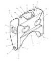
- FIG. 1is a perspective view of an interspinous spacer according to one example embodiment and in use and affixed between a superior spinous process and an inferior spinous process of a human spine;
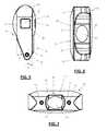
- FIG. 2is a perspective view of the interspinous spacer according to the embodiment shown in FIG. 1 ;
- FIG. 3is a posterior view of the interspinous spacer according to the embodiment shown in FIG. 1 ;
- FIG. 4is an anterior view of the interspinous spacer according to the embodiment shown in FIG. 1 ;
- FIG. 5is a side view of the interspinous spacer according to the embodiment shown in FIG. 1 ;
- FIG. 6is a bottom view of the interspinous spacer according to the embodiment shown in FIG. 1 ;
- FIG. 7is a top view of the interspinous spacer according to the embodiment shown in FIG. 1 ;
- FIG. 8is a cross-sectional view of the interspinous spacer according to the embodiment shown in FIG. 1 ;
- FIG. 9is a perspective view of the interspinous spacer according to the embodiment shown in FIG. 1 with markers exploded;
- FIG. 10is a perspective view of an insertion instrument according to one example embodiment used to install the interspinous spacer of FIG. 1 ;
- FIG. 11is a posterior view of the insertion instrument attached to the interspinous spacer of FIG. 1 in preparation for introduction to a target site;
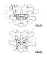
- FIGS. 12-14illustrate in progressive fashion the insertion of the spacer in a first orientation having a diminished height and then the rotating of the spacer to effect distraction of the interspinous space, according to one example embodiment of the present invention.
- FIG. 1illustrates a perspective view of a spinous process spacer 10 of the present invention in use between two spinous processes in a human spine.
- Spacer 10includes a top surface 11 , posterior side 12 , bottom surface 13 , lateral sides 14 , and anterior side 16 .
- Top surface 11may further include superior fusion notch 20
- bottom surface 13may further include inferior fusion notch 22 .
- Spacer 10may be further provided with a plurality of fusion apertures including, but not limited to, superior fusion aperture 21 , inferior fusion aperture 23 and posterior fusion apertures 24 all linked to a main cavity 17 .
- Insertion apertures 26may be provided on lateral sides 14 .
- spacer 10may preferably be coupled to both a superior and inferior spinal process. This may be accomplished, by way of example only, by snugly positioning spacer 10 between both spinous processes and allowing boney ingrowths to form between the superior and inferior spinous processes through spacer 10 .
- spacer 10is constructed of non-bone material.
- Suitable non-bone materialsmay include, but are not necessarily limited to, polyaryletherketone, polyetheretherketon (PEEK) and polyaryletherketoneketone (PEKK).
- PEEKpolyetheretherketon
- PEKKpolyaryletherketoneketone
- One advantageis the stiffness properties of PEEK and PEKK closely match that of bone which substantially reduces the likelihood that the spinous process will remodel around spacer 10 causing a re-narrowing of the foraminal height and potentially resulting in the potential need for revision surgery.
- PEEK and PEKKare also substantially radiolucent which allows for improved post operative visualization of fusion between the superior and inferior spinous processes through spacer 10 .
- Spacer 10is designed to maintain the interspinous space between the spinous processes and prevent over extension while boney fusion takes place between the spinous process over time.
- the fusion processmay be augmented by disposing any number of suitable fusion-inducing materials 28 within the main cavity 17 , including but not limited to BMP (bone morphogenic protein) 1 , 2 , 3 , 4 , 5 , 6 , 7 , 8 , 9 , 10 , 11 , 12 , 13 , 14 . . . n, demineralized bone matrix, allograft cancellous bone, autograft bone, hydroxyapetite, coral and/or other highly porous substance.
- BMPbone morphogenic protein
- the fusion inducing material 28may be packed within main cavity 17 to thereby communicate openly with the superior and inferior spinous processes through any of the insertion instrument apertures 26 and/or fusion apertures 21 , 23 and 24 . Through this communication, fusion may occur between the superior and inferior spinous processes through the main cavity 17 , fixing spacer 10 in position.
- the cross section of the main cavity 17is shaped and dimensioned to allow for a sufficient amount of bone growth to form through the cavity, thus fusing and securing the spacer 10 in the interspinous process space.
- the main cavity 17is shown as being elliptical in shape with a length dimension of approximately 5 mm and a height dimension ranging from approximately 3 mm and 5 mm.
- main cavity 17is shown and described as being elliptical in shape with the aforementioned dimensions, the main cavity 17 may be any shape and dimensions appropriate to allow secure bone fusion of the spacer 10 to the surrounding spinous processes without departing from the scope of the present invention.
- FIG. 2is a perspective view of the spacer 10 .
- FIG. 3is an illustration of posterior side 12 of spacer 10 .
- Superior fusion notch 20may be located generally on the top surface 11 and centrally positioned between the two lateral sides 14 .
- Fusion notch 20generally comprises of a slot or indent dimensioned to receive an inferior portion of a superior spinous process. Fusion notch 20 may help center spacer 10 relative to the superior spinous process and may assist in limiting lateral motion of spacer 10 prior to fusion.
- Fusion notch 20includes superior fusion aperture 21 (best viewed in FIG.
- fusion apertures 24may also be provided on posterior side 24 .
- Posterior fusion apertures 24may provide an additional avenue for boney growth around the exterior of spacer 10 and may also be used to pack main cavity 17 with fusion promoting materials before and/or after insertion of spacer 10 .
- the spacer 10is shaped such that the greatest height between the top and bottom surface 11 , 13 of the spacer 10 exist along the lateral sides 14 , forming legs 9 extending below a central body portion.
- the legs 9 of the spacer 10are increasingly tapered as they converge towards the bottom surface 13 (best shown in FIG. 5 and FIG. 8 ).
- the anterior side 16 of the legs 9taper towards the posterior side 12 of the legs 9 , having a taper angle ⁇ ( FIG. 5 ).
- angle ⁇may be approximately 15 to 30 degrees.
- the posterior sides 12 of the legs 9begin to taper towards the anterior sides 16 of the legs 9 near the bottom surface 13 , having a taper angle ⁇ ( FIG. 5 ).
- angle ⁇may be approximately 20 to 40 degrees.
- the bottom surface 13provides a rounded transition between the anterior and posterior sides 16 , 12 of the legs 9 . Tapering of the legs 9 also occurs in the lateral direction due to the increasing radii of the inferior fusion notch and the medial surface, as will be discussed in more detail below.
- the taper of legs 9facilitate insertion and through and around tissue (e.g. supra spinous ligament) and distraction of the interspinous space during insertion.
- An inferior fusion notch 22is located generally along the inferior surface of the spacer and is generally positioned centrally between the lateral sides 14 .
- Inferior fusion notch 22is generally comprised of an angled concave surface dimensioned to receive a superior portion of an inferior spinous process. Fusion notch 22 also helps center spacer 10 relative to the inferior spinous process and may assist in limiting lateral motion of spacer 10 prior to fusion.
- Inferior fusion notch 22includes an inferior fusion aperture 23 which extends into main cavity 17 and is the primary passage for fusion between main cavity 17 and the inferior spinous process.
- FIG. 3illustrates the medial surface 15 having a generally concave configuration from the bottom surface of legs 9 to the inferior fusion notch 22 .
- the concave inferior fusion notch 22may have a radius dimension of approximately 5 mm to 8 mm and the concave medial surfaces 15 may have a radius dimension of approximately 10 mm to 15 mm.
- the more narrow fusion notch 22generally assists in maintaining the final positioning of the spacer 10 until fusion occurs while the broader arc of the medial surfaces 15 aid in the insertion of the spacer 10 within an interspinous process space, as described below.
- Fusion apertures 21 , 23 and 24may be provided in any of a variety of shapes in addition to the generally oval shapes shown, including but not necessarily limited to, generally square, rectangular, circular, triangular and/or any combination thereof.
- Insertion instrument apertures 18are positioned along the lateral sides 14 to facilitate introduction of the spacer into a desired position. For example, the spacer may be introduced without sacrificing the supraspinous ligament.
- the insertion instrument aperture 18is a non-circular shape. The non-circular shape of the insertion instrument aperture 18 restricts the relative rotation between the insertion instrument and the spacer while rotating the spacer 10 to the desired interspinous position during introduction.
- the insertion apertures 18may have a square profile with height and width dimensions generally in the range of 3 mm to 5 mm.
- the shape and dimensions of the insertion apertures 18may be any shape and dimension appropriate to permit the desired insertion and rotation of the spacer 10 .
- FIG. 4is an illustration of anterior side 16 of spacer 10 .
- the anterior surfaceis generally curved to accommodate a smooth transition during insertion and rotation of the spacer 10 into the desired position within the interspinous space.
- the anterior side 16faces the spinal canal.
- there are no fusion apertures along the anterior side 16 of the spacer 10which protects the dura and prevents graft material from falling into the dura from within the spacer 10 .
- Both posterior side 12 and anterior side 16have angled surfaces 27 and 29 , respectively, near lateral sides 14 to further accommodate the installation process as described below.
- angled surfaces 27 and 29ensure that there are no sharp edges that can damage any surrounding bone or tissue during implantation of the spacer 10 .
- the angled surfaces 27 and 29also assist in clearance of the lamina and facet joints during introduction and positioning of the implant.
- Both the anterior and posterior surfaces of the spacer 10are generally convex to provide for a smooth transition during insertion and rotation of the spacer 10 into a desired position within the interspinous space.
- the greatest distance between the convex anterior and posterior surfacesis less than the shortest distance between the inferior and superior fusion notches 22 , 20 .
- the spaceris inserted in a horizontal position and then rotated into a vertical position, as will be discussed in greater detail below.
- 2 mm to 6 mm of distractioncan be effected upon rotation of the spacer 10 within the interspinous process space.
- more or less distractioncan be accomplished using the spacer 10 without departing from the scope of the present invention.
- FIG. 5is an illustration of a lateral side 14 of spacer 10 .
- Insertion apertures 26may be provided on lateral sides 14 and preferably connect into main cavity. Apertures 26 are provided on both lateral sides 14 such that spacer 10 may be inserted from either side of the patient. Apertures 26 are dimensioned to receive insertion head 34 of insertion instrument 30 as described below.
- FIG. 6is a bottom view of spacer 10 .
- FIG. 7is a top view of spacer 10 . Top surface 11 of spacer 10 is generally curved and tapers at an angle to the lateral sides 14 .
- main cavity 17may preferably be formed from horizontal cavity 18 and vertical cavity 19 .
- Horizontal cavity 18preferably spans across insertion apertures 26 .
- Horizontal cavity 18may be provided in any variety of shapes in addition to the generally square shape shown, including but not necessarily limited to, generally rectangular, circular, oblong, triangular and/or any combination thereof.
- Vertical cavity 19preferably spans across fusion apertures 21 and 23 .
- Vertical cavity 19may be provided in any variety of shapes in addition to the generally oblong shape shown, including but not necessarily limited to, generally rectangular, circular, oblong, triangular and/or any combination thereof.
- the main cavity 17has a generally cross-shaped pattern.
- spacer 10may include at least one marker.
- FIG. 9shows in exploded view, by example only, four markers situated within spacer 10 .
- spacer 10includes two top markers 40 and two side marker 42 .
- Markers 40 and 42may be comprised of biocompatible radiopaque material, such as, for example only, titanium (or other metals or polymers).
- Markers 40may be positioned along top surface 11 of spacer 10 on either side of fusion notch 20 .
- Markers 42may be located in lateral sides 14 below main cavity 17 and preferably adjacent to bottom surface 13 .
- markers 40 and 42may be viewable using X-ray fluoroscopy to ensure spacer 10 is correctly oriented in the interspinous space.
- FIG. 10shows an example embodiment of an insertion instrument 30 .
- Insertion instrument 30consists of insertion head 34 connected by an elongated body 36 to handgrip 38 .
- Insertion head 34is oriented at a non-straight angle relative to the longitudinal axis 35 of the instrument 30 .
- the insertion head 34is configured and shaped to be received by either insertion aperture 26 of the spacer 10 .
- the cross-sectional geometry of the insertion head 34may be shaped in any of a variety of shapes in addition to the generally square shape shown, including, but not necessarily limited to, generally rectangular, oblong, triangular and/or any combination thereof, such that insertion head 34 matches the shape of the insertion aperture 26 .
- the insertion head 34may include a slight increasing taper from the tip of head 34 to the body 36 .
- the tapered head 34interacts with the insertion aperture 26 on the implant 10 to cause a friction fit connection and releasably maintain the spacer 10 on the insertion instrument 30 during the implantation process.
- FIG. 11shows insertion instrument 30 inserted into spacer 10 via insertion aperture 26 .
- the insertion instrument 30may be connected to an insertion aperture 26 located on either side of the spacer 10 .
- spacer 10may be positioned on the insertion head 34 such that the vertical orientation of the spacer 10 forms a non-right angle with the longitudinal axis of the instrument 30 . This angular offset between the spacer 10 and the instrument 30 may facilitate the rotation of the spacer from the first insertion position to the second distraction position, which will be described in more detail below.
- a cliniciancan utilize the spacer 10 in either an open or minimally invasive spinal fusion procedure.
- a working channelis created in a patient that reaches a targeted spinal level.
- the interspinous spaceis prepared.
- the interspinous spaceis prepared by removing at least a portion of the interspinous ligament and preferably abrading the superior and inferior spinous processes. Abrading the spinous processes includes abrading the inferior portion of the superior spinous process and the superior portion of the inferior spinous process. This allows the abraded surfaces to communicate with the fusion promoting materials packed in the main cavity 17 through a superior fusion aperture and inferior fusion aperture of the spacer 10 .
- Abradingremoves the hard cortical bone from the surface of the bone and exposes the softer bleeding cancellous bone underneath, which is better adapted for fusion.
- the new bonemay communicate with the fusion promoting materials and grow into the main cavity 17 of the spacer 10 , thus fixing the spacer 10 to both the superior and inferior spinous processes.
- a sizer instrumentmay be used to determine the appropriate size of the spacer required to achieve the desired correction.
- the spacermay be inserted in a horizontal position having an initial height less than the desired corrected height of the interspinous space and then rotated to a final vertical position thereby distracting the interspinous space to the desired height.
- the surgeonwill use an insertion instrument 30 to guide the spacer 10 in between the spinous processes, leading with the bottom surface 13 and guiding one of the legs 9 around the supraspinous ligament.
- the tapered end of leg 9aids in passing the leg under the supraspinous ligament and can also distract the spinous processes if necessary.
- the spacer 10may be axially rotated in the transverse plane to an intermediate position. To get to the intermediate position, the spacer may be rotated approximately 90 degrees such that the top surface 11 faces the spinal canal. From the intermediate position, the spacer 10 may be adjusted into the final position by rotating the spacer again, this time in the sagittal plane. The spacer may be rotated approximately 90 degrees such that the top surface faces the superior spinous process above. As the spacer is rotated into the final position the height of the implant distracts the spinal processes and prevents over extension. X-Ray fluoroscopy or other suitable imaging techniques may be used to verify the spacer 10 is properly positioned. The instrument 30 is removed from the spacer 10 and the working channel is closed.
Landscapes
- Health & Medical Sciences (AREA)
- Orthopedic Medicine & Surgery (AREA)
- Life Sciences & Earth Sciences (AREA)
- Neurology (AREA)
- Surgery (AREA)
- Heart & Thoracic Surgery (AREA)
- Engineering & Computer Science (AREA)
- Biomedical Technology (AREA)
- Nuclear Medicine, Radiotherapy & Molecular Imaging (AREA)
- Medical Informatics (AREA)
- Molecular Biology (AREA)
- Animal Behavior & Ethology (AREA)
- General Health & Medical Sciences (AREA)
- Public Health (AREA)
- Veterinary Medicine (AREA)
- Prostheses (AREA)
Abstract
Description
Claims (16)
Priority Applications (1)
| Application Number | Priority Date | Filing Date | Title |
|---|---|---|---|
| US12/578,577US8292923B1 (en) | 2008-10-13 | 2009-10-13 | Systems and methods for treating spinal stenosis |
Applications Claiming Priority (2)
| Application Number | Priority Date | Filing Date | Title |
|---|---|---|---|
| US10501108P | 2008-10-13 | 2008-10-13 | |
| US12/578,577US8292923B1 (en) | 2008-10-13 | 2009-10-13 | Systems and methods for treating spinal stenosis |
Publications (1)
| Publication Number | Publication Date |
|---|---|
| US8292923B1true US8292923B1 (en) | 2012-10-23 |
Family
ID=47017361
Family Applications (1)
| Application Number | Title | Priority Date | Filing Date |
|---|---|---|---|
| US12/578,577Active2030-03-02US8292923B1 (en) | 2008-10-13 | 2009-10-13 | Systems and methods for treating spinal stenosis |
Country Status (1)
| Country | Link |
|---|---|
| US (1) | US8292923B1 (en) |
Cited By (6)
| Publication number | Priority date | Publication date | Assignee | Title |
|---|---|---|---|---|
| US20150088201A1 (en)* | 2011-02-23 | 2015-03-26 | Farzad Massoudi | Spinal implant device with fusion cage and fixation plates and method of implanting |
| FR3011458A1 (en)* | 2013-10-07 | 2015-04-10 | Cousin Biotech | IMPLANTABLE VERTEBRAL ARTHRODESIS DEVICE FOR FUSION BETWEEN TWO UNDERGROUND AND UNDERLYING VERTEBRES. |
| US9956007B2 (en) | 2011-11-17 | 2018-05-01 | Howmedica Osteonics Corp. | Interspinous spacers and associated methods of use and manufacture |
| US20220168022A1 (en)* | 2011-09-06 | 2022-06-02 | Atul Goel | Devices and Method for Treatment of Spondylotic Disease |
| CN115474973A (en)* | 2021-06-16 | 2022-12-16 | 兆峰生技股份有限公司 | Apparatus and method for spreading support between spinous processes |
| US20220401134A1 (en)* | 2021-06-16 | 2022-12-22 | Megaspine Medical Co., Ltd. | Device and method for expanding spacing between spinous processes |
Citations (27)
| Publication number | Priority date | Publication date | Assignee | Title |
|---|---|---|---|---|
| US5011484A (en) | 1987-11-16 | 1991-04-30 | Breard Francis H | Surgical implant for restricting the relative movement of vertebrae |
| US5645599A (en) | 1994-07-26 | 1997-07-08 | Fixano | Interspinal vertebral implant |
| US5836948A (en) | 1997-01-02 | 1998-11-17 | Saint Francis Medical Technologies, Llc | Spine distraction implant and method |
| US20010020188A1 (en) | 1997-10-27 | 2001-09-06 | Tom Sander | Selective uptake of materials by bone implants |
| US20010021850A1 (en) | 1997-01-02 | 2001-09-13 | St. Francis Medical Technologies, Inc. | Spine distraction implant |
| US20030040746A1 (en) | 2001-07-20 | 2003-02-27 | Mitchell Margaret E. | Spinal stabilization system and method |
| US20030045935A1 (en) | 2001-02-28 | 2003-03-06 | Angelucci Christopher M. | Laminoplasty implants and methods of use |
| US6558387B2 (en) | 2001-01-30 | 2003-05-06 | Fastemetix, Llc | Porous interbody fusion device having integrated polyaxial locking interference screws |
| US20040019356A1 (en) | 2002-07-23 | 2004-01-29 | Robert Fraser | Surgical trial implant |
| US6695882B2 (en) | 1997-06-03 | 2004-02-24 | Sdgi Holdings, Inc. | Open intervertebral spacer |
| US6699247B2 (en) | 1997-01-02 | 2004-03-02 | St. Francis Medical Technologies, Inc. | Spine distraction implant |
| US6761720B1 (en) | 1999-10-15 | 2004-07-13 | Spine Next | Intervertebral implant |
| US20050165398A1 (en) | 2004-01-26 | 2005-07-28 | Reiley Mark A. | Percutaneous spine distraction implant systems and methods |
| US20060085070A1 (en)* | 2004-10-20 | 2006-04-20 | Vertiflex, Inc. | Systems and methods for posterior dynamic stabilization of the spine |
| US20060106381A1 (en) | 2004-11-18 | 2006-05-18 | Ferree Bret A | Methods and apparatus for treating spinal stenosis |
| US20060235532A1 (en) | 2003-01-20 | 2006-10-19 | Abbott Spine | Unit for treatment of the degeneration of an intervertebral disc |
| US20060247634A1 (en) | 2005-05-02 | 2006-11-02 | Warner Kenneth D | Spinous Process Spacer Implant and Technique |
| US20060293662A1 (en)* | 2005-06-13 | 2006-12-28 | Boyer Michael L Ii | Spinous process spacer |
| US20070032790A1 (en) | 2005-08-05 | 2007-02-08 | Felix Aschmann | Apparatus for treating spinal stenosis |
| US20070043361A1 (en) | 2005-02-17 | 2007-02-22 | Malandain Hugues F | Percutaneous spinal implants and methods |
| US20070073292A1 (en)* | 2005-02-17 | 2007-03-29 | Kohm Andrew C | Percutaneous spinal implants and methods |
| US7201775B2 (en) | 2002-09-24 | 2007-04-10 | Bogomir Gorensek | Stabilizing device for intervertebral disc, and methods thereof |
| US20070093825A1 (en)* | 2005-09-28 | 2007-04-26 | Nuvasive Inc. | Methods and apparatus for treating spinal stenosis |
| US20070093823A1 (en) | 2005-09-29 | 2007-04-26 | Nuvasive, Inc. | Spinal distraction device and methods of manufacture and use |
| US20080015701A1 (en)* | 2001-11-09 | 2008-01-17 | Javier Garcia | Spinal implant |
| US20080027438A1 (en) | 2006-07-27 | 2008-01-31 | Abdou M S | Devices and methods for the minimally invasive treatment of spinal stenosis |
| US20080319549A1 (en)* | 2005-12-28 | 2008-12-25 | Stout Medical Group, L.P. | Expandable support device and method of use |
- 2009
- 2009-10-13USUS12/578,577patent/US8292923B1/enactiveActive
Patent Citations (29)
| Publication number | Priority date | Publication date | Assignee | Title |
|---|---|---|---|---|
| US5011484A (en) | 1987-11-16 | 1991-04-30 | Breard Francis H | Surgical implant for restricting the relative movement of vertebrae |
| US5645599A (en) | 1994-07-26 | 1997-07-08 | Fixano | Interspinal vertebral implant |
| US5836948A (en) | 1997-01-02 | 1998-11-17 | Saint Francis Medical Technologies, Llc | Spine distraction implant and method |
| US20010021850A1 (en) | 1997-01-02 | 2001-09-13 | St. Francis Medical Technologies, Inc. | Spine distraction implant |
| US6699247B2 (en) | 1997-01-02 | 2004-03-02 | St. Francis Medical Technologies, Inc. | Spine distraction implant |
| US6695882B2 (en) | 1997-06-03 | 2004-02-24 | Sdgi Holdings, Inc. | Open intervertebral spacer |
| US7273498B2 (en) | 1997-06-03 | 2007-09-25 | Warsaw Orthopedic, Inc. | Open intervertebral spacer |
| US20010020188A1 (en) | 1997-10-27 | 2001-09-06 | Tom Sander | Selective uptake of materials by bone implants |
| US6761720B1 (en) | 1999-10-15 | 2004-07-13 | Spine Next | Intervertebral implant |
| US6558387B2 (en) | 2001-01-30 | 2003-05-06 | Fastemetix, Llc | Porous interbody fusion device having integrated polyaxial locking interference screws |
| US20030045935A1 (en) | 2001-02-28 | 2003-03-06 | Angelucci Christopher M. | Laminoplasty implants and methods of use |
| US20030040746A1 (en) | 2001-07-20 | 2003-02-27 | Mitchell Margaret E. | Spinal stabilization system and method |
| US20080015701A1 (en)* | 2001-11-09 | 2008-01-17 | Javier Garcia | Spinal implant |
| US20040019356A1 (en) | 2002-07-23 | 2004-01-29 | Robert Fraser | Surgical trial implant |
| US6723097B2 (en) | 2002-07-23 | 2004-04-20 | Depuy Spine, Inc. | Surgical trial implant |
| US7201775B2 (en) | 2002-09-24 | 2007-04-10 | Bogomir Gorensek | Stabilizing device for intervertebral disc, and methods thereof |
| US20060235532A1 (en) | 2003-01-20 | 2006-10-19 | Abbott Spine | Unit for treatment of the degeneration of an intervertebral disc |
| US20050165398A1 (en) | 2004-01-26 | 2005-07-28 | Reiley Mark A. | Percutaneous spine distraction implant systems and methods |
| US20060085070A1 (en)* | 2004-10-20 | 2006-04-20 | Vertiflex, Inc. | Systems and methods for posterior dynamic stabilization of the spine |
| US20060106381A1 (en) | 2004-11-18 | 2006-05-18 | Ferree Bret A | Methods and apparatus for treating spinal stenosis |
| US20070043361A1 (en) | 2005-02-17 | 2007-02-22 | Malandain Hugues F | Percutaneous spinal implants and methods |
| US20070073292A1 (en)* | 2005-02-17 | 2007-03-29 | Kohm Andrew C | Percutaneous spinal implants and methods |
| US20060247634A1 (en) | 2005-05-02 | 2006-11-02 | Warner Kenneth D | Spinous Process Spacer Implant and Technique |
| US20060293662A1 (en)* | 2005-06-13 | 2006-12-28 | Boyer Michael L Ii | Spinous process spacer |
| US20070032790A1 (en) | 2005-08-05 | 2007-02-08 | Felix Aschmann | Apparatus for treating spinal stenosis |
| US20070093825A1 (en)* | 2005-09-28 | 2007-04-26 | Nuvasive Inc. | Methods and apparatus for treating spinal stenosis |
| US20070093823A1 (en) | 2005-09-29 | 2007-04-26 | Nuvasive, Inc. | Spinal distraction device and methods of manufacture and use |
| US20080319549A1 (en)* | 2005-12-28 | 2008-12-25 | Stout Medical Group, L.P. | Expandable support device and method of use |
| US20080027438A1 (en) | 2006-07-27 | 2008-01-31 | Abdou M S | Devices and methods for the minimally invasive treatment of spinal stenosis |
Cited By (15)
| Publication number | Priority date | Publication date | Assignee | Title |
|---|---|---|---|---|
| US20150088201A1 (en)* | 2011-02-23 | 2015-03-26 | Farzad Massoudi | Spinal implant device with fusion cage and fixation plates and method of implanting |
| US10052138B2 (en)* | 2011-02-23 | 2018-08-21 | Farzad Massoudi | Method for implanting spinal implant device with fusion cage |
| US20170035466A1 (en)* | 2011-02-23 | 2017-02-09 | Farzad Massoudi | Method for implanting spinal implant device with fusion cage |
| US12064147B2 (en)* | 2011-09-06 | 2024-08-20 | Atul Goel | Devices and method for treatment of spondylotic disease |
| US20220168022A1 (en)* | 2011-09-06 | 2022-06-02 | Atul Goel | Devices and Method for Treatment of Spondylotic Disease |
| US9956007B2 (en) | 2011-11-17 | 2018-05-01 | Howmedica Osteonics Corp. | Interspinous spacers and associated methods of use and manufacture |
| US10945769B2 (en) | 2011-11-17 | 2021-03-16 | Howmedica Osteonics Corp. | Interspinous spacers and associated methods of use and manufacture |
| US11707302B2 (en) | 2011-11-17 | 2023-07-25 | Howmedica Osteonics Corp. | Interspinous spacers and associated methods of use and manufacture |
| US9833266B2 (en)* | 2013-10-07 | 2017-12-05 | Cousin Biotech | Implantable vertebral arthrodesis device for fusing two overlying and underlying vertebrae |
| US20160242821A1 (en)* | 2013-10-07 | 2016-08-25 | Cousin Biotech | Implantable vertebral arthrodesis device for fusing two overlying and underlying vertebrae |
| WO2015052431A1 (en) | 2013-10-07 | 2015-04-16 | Cousin Biotech | Implantable vertebral arthrodesis device for fusing two overlying and underlying vertebrae |
| FR3011458A1 (en)* | 2013-10-07 | 2015-04-10 | Cousin Biotech | IMPLANTABLE VERTEBRAL ARTHRODESIS DEVICE FOR FUSION BETWEEN TWO UNDERGROUND AND UNDERLYING VERTEBRES. |
| CN115474973A (en)* | 2021-06-16 | 2022-12-16 | 兆峰生技股份有限公司 | Apparatus and method for spreading support between spinous processes |
| US20220401134A1 (en)* | 2021-06-16 | 2022-12-22 | Megaspine Medical Co., Ltd. | Device and method for expanding spacing between spinous processes |
| US11779375B2 (en)* | 2021-06-16 | 2023-10-10 | Megaspine Medical Co., Ltd. | Device and method for expanding spacing between spinous processes |
Similar Documents
| Publication | Publication Date | Title |
|---|---|---|
| EP3049030B1 (en) | Intrabody osteotomy implant | |
| US8167915B2 (en) | Methods and apparatus for treating spinal stenosis | |
| US7862592B2 (en) | Methods and apparatus for treating spinal stenosis | |
| CN108852562A (en) | The interbody implants and radial type inserter and application method of expansion | |
| CN108498150A (en) | spinal implant system and method | |
| US20120239089A1 (en) | Interspinous process implant and method of implantation | |
| WO2009061589A2 (en) | In-situ curable interspinous process spacer | |
| US12370060B2 (en) | Methods and devices for altering spinal lordosis and/or kyphosis during spinal fusion | |
| US8292923B1 (en) | Systems and methods for treating spinal stenosis | |
| CN113727676A (en) | Spinal Implant Systems and Methods | |
| US20200054460A1 (en) | Intrabody Osteotomy Implant and Methods of Use | |
| EP3015084B1 (en) | Spinal fixation member | |
| US20120016420A1 (en) | Devices, systems, and methods for inter-transverse process dynamic stabilization | |
| AU2024200466A1 (en) | Spinal osteotomy | |
| US20180185078A1 (en) | Inter-laminar vertebral implant apparatus and methods of implanation | |
| JP7357636B2 (en) | Monolithic implants and methods for cervical spine fusion surgery | |
| US20240206920A1 (en) | System and method for lumbar fusion | |
| US20240180596A1 (en) | System and method for correction of spine deformation | |
| US20120245693A1 (en) | Spinal fixation device | |
| US9561059B1 (en) | Minimally invasive facet release | |
| CN113747862A (en) | Spinal implant system and method | |
| US10485677B2 (en) | Lumbar fusion | |
| JP2008100079A (en) | Method and apparatus for treating spinal stenosis |
Legal Events
| Date | Code | Title | Description |
|---|---|---|---|
| AS | Assignment | Owner name:NUVASIVE, INC., CALIFORNIA Free format text:ASSIGNMENT OF ASSIGNORS INTEREST;ASSIGNORS:ARNOLD, BENJAMIN;MALIK, JEREMY;BAE, HYUN;AND OTHERS;SIGNING DATES FROM 20091009 TO 20100201;REEL/FRAME:023880/0742 | |
| STCF | Information on status: patent grant | Free format text:PATENTED CASE | |
| FPAY | Fee payment | Year of fee payment:4 | |
| AS | Assignment | Owner name:BANK OF AMERICA, N.A., AS ADMINISTRATIVE AGENT, CALIFORNIA Free format text:NOTICE OF GRANT OF SECURITY INTEREST IN PATENTS;ASSIGNORS:NUVASIVE, INC.;IMPULSE MONITORING, INC.;REEL/FRAME:040634/0404 Effective date:20160208 Owner name:BANK OF AMERICA, N.A., AS ADMINISTRATIVE AGENT, CA Free format text:NOTICE OF GRANT OF SECURITY INTEREST IN PATENTS;ASSIGNORS:NUVASIVE, INC.;IMPULSE MONITORING, INC.;REEL/FRAME:040634/0404 Effective date:20160208 | |
| AS | Assignment | Owner name:BANK OF AMERICA, N.A., AS ADMINISTRATIVE AGENT, TE Free format text:NOTICE OF GRANT OF SECURITY INTEREST IN PATENTS;ASSIGNORS:NUVASIVE, INC.;BIOTRONIC NATIONAL, LLC;NUVASIVE CLINICAL SERVICES MONITORING, INC.;AND OTHERS;REEL/FRAME:042490/0236 Effective date:20170425 Owner name:BANK OF AMERICA, N.A., AS ADMINISTRATIVE AGENT, TEXAS Free format text:NOTICE OF GRANT OF SECURITY INTEREST IN PATENTS;ASSIGNORS:NUVASIVE, INC.;BIOTRONIC NATIONAL, LLC;NUVASIVE CLINICAL SERVICES MONITORING, INC.;AND OTHERS;REEL/FRAME:042490/0236 Effective date:20170425 | |
| AS | Assignment | Owner name:BANK OF AMERICA, N.A., AS ADMINISTRATIVE AGENT, NORTH CAROLINA Free format text:SECURITY INTEREST;ASSIGNORS:NUVASIVE, INC.;NUVASIVE CLINICAL SERVICES MONITORING, INC.;NUVASIVE CLINICAL SERVICES, INC.;AND OTHERS;REEL/FRAME:052918/0595 Effective date:20200224 | |
| MAFP | Maintenance fee payment | Free format text:PAYMENT OF MAINTENANCE FEE, 8TH YEAR, LARGE ENTITY (ORIGINAL EVENT CODE: M1552); ENTITY STATUS OF PATENT OWNER: LARGE ENTITY Year of fee payment:8 | |
| MAFP | Maintenance fee payment | Free format text:PAYMENT OF MAINTENANCE FEE, 12TH YEAR, LARGE ENTITY (ORIGINAL EVENT CODE: M1553); ENTITY STATUS OF PATENT OWNER: LARGE ENTITY Year of fee payment:12 |