US8292767B2 - Powertrain having a multi-speed transmission - Google Patents
Powertrain having a multi-speed transmissionDownload PDFInfo
- Publication number
- US8292767B2 US8292767B2US12/463,713US46371309AUS8292767B2US 8292767 B2US8292767 B2US 8292767B2US 46371309 AUS46371309 AUS 46371309AUS 8292767 B2US8292767 B2US 8292767B2
- Authority
- US
- United States
- Prior art keywords
- planetary gear
- gear set
- transmission
- clutch
- powertrain
- Prior art date
- Legal status (The legal status is an assumption and is not a legal conclusion. Google has not performed a legal analysis and makes no representation as to the accuracy of the status listed.)
- Expired - Fee Related, expires
Links
- 230000005540biological transmissionEffects0.000titleclaimsabstractdescription126
- 230000008878couplingEffects0.000claimsabstractdescription12
- 238000010168coupling processMethods0.000claimsabstractdescription12
- 238000005859coupling reactionMethods0.000claimsabstractdescription12
- 239000006249magnetic particleSubstances0.000claimsdescription3
- 238000002485combustion reactionMethods0.000claims2
- 230000007246mechanismEffects0.000description11
- 230000008901benefitEffects0.000description3
- 238000004806packaging method and processMethods0.000description3
- 210000000078clawAnatomy0.000description1
- 238000010586diagramMethods0.000description1
- 238000004519manufacturing processMethods0.000description1
- 238000005259measurementMethods0.000description1
- 230000004043responsivenessEffects0.000description1
Images


Classifications
- F—MECHANICAL ENGINEERING; LIGHTING; HEATING; WEAPONS; BLASTING
- F16—ENGINEERING ELEMENTS AND UNITS; GENERAL MEASURES FOR PRODUCING AND MAINTAINING EFFECTIVE FUNCTIONING OF MACHINES OR INSTALLATIONS; THERMAL INSULATION IN GENERAL
- F16H—GEARING
- F16H3/00—Toothed gearings for conveying rotary motion with variable gear ratio or for reversing rotary motion
- F16H3/44—Toothed gearings for conveying rotary motion with variable gear ratio or for reversing rotary motion using gears having orbital motion
- F16H3/62—Gearings having three or more central gears
- F16H3/66—Gearings having three or more central gears composed of a number of gear trains without drive passing from one train to another
- F—MECHANICAL ENGINEERING; LIGHTING; HEATING; WEAPONS; BLASTING
- F16—ENGINEERING ELEMENTS AND UNITS; GENERAL MEASURES FOR PRODUCING AND MAINTAINING EFFECTIVE FUNCTIONING OF MACHINES OR INSTALLATIONS; THERMAL INSULATION IN GENERAL
- F16H—GEARING
- F16H2200/00—Transmissions for multiple ratios
- F16H2200/003—Transmissions for multiple ratios characterised by the number of forward speeds
- F16H2200/006—Transmissions for multiple ratios characterised by the number of forward speeds the gear ratios comprising eight forward speeds
- F—MECHANICAL ENGINEERING; LIGHTING; HEATING; WEAPONS; BLASTING
- F16—ENGINEERING ELEMENTS AND UNITS; GENERAL MEASURES FOR PRODUCING AND MAINTAINING EFFECTIVE FUNCTIONING OF MACHINES OR INSTALLATIONS; THERMAL INSULATION IN GENERAL
- F16H—GEARING
- F16H2200/00—Transmissions for multiple ratios
- F16H2200/20—Transmissions using gears with orbital motion
- F16H2200/2002—Transmissions using gears with orbital motion characterised by the number of sets of orbital gears
- F16H2200/2012—Transmissions using gears with orbital motion characterised by the number of sets of orbital gears with four sets of orbital gears
- F—MECHANICAL ENGINEERING; LIGHTING; HEATING; WEAPONS; BLASTING
- F16—ENGINEERING ELEMENTS AND UNITS; GENERAL MEASURES FOR PRODUCING AND MAINTAINING EFFECTIVE FUNCTIONING OF MACHINES OR INSTALLATIONS; THERMAL INSULATION IN GENERAL
- F16H—GEARING
- F16H2200/00—Transmissions for multiple ratios
- F16H2200/20—Transmissions using gears with orbital motion
- F16H2200/203—Transmissions using gears with orbital motion characterised by the engaging friction means not of the freewheel type, e.g. friction clutches or brakes
- F16H2200/2043—Transmissions using gears with orbital motion characterised by the engaging friction means not of the freewheel type, e.g. friction clutches or brakes with five engaging means
Definitions
- the inventionrelates generally to a multiple speed transmission having a plurality of planetary gear sets and a plurality of torque transmitting devices and more particularly to a transmission having eight or more speeds.
- a typical multiple speed transmissionuses a combination of a plurality of torque transmitting mechanisms, planetary gear arrangements and fixed interconnections to achieve a plurality of gear ratios.
- the number and physical arrangement of the planetary gear setsgenerally, are dictated by packaging, cost and desired speed ratios.
- a powertrainhaving a multi-speed transmission.
- the transmissionis provided having an input member, an output member, a plurality of planetary gear sets, and a plurality of torque-transmitting mechanisms.
- the plurality of planetary gear setseach have a sun gear member, a planetary carrier member and a ring gear member.
- the powertrainmay be configured as a front wheel drive powertrain where the input and output shafts of the transmission are provided on the same side.
- the powertrain of the present inventionmay be configured as a rear wheel drive powertrain having the input and output shafts of the transmission on opposite sides of the transmission.
- a one-way clutchis provided which is connectable to the transmission, in accordance with an embodiment of the present invention.
- the transmissionis coupled to a differential in a first arrangement where the transmission and transmission output member is perpendicular to a pair of drive axles, in accordance with an embodiment of the present invention.
- the transmissionis coupled to a differential in a second arrangement where the transmission and transmission output member is parallel to a pair of drive axles, in accordance with an embodiment of the present invention.
- a drive motor and a coupling deviceare connectable to the transmission, in accordance with an embodiment of the present invention.
- the powertrain of the present inventionhas a transmission arranged between a drive motor and a coupling device, in accordance with an embodiment of the present invention.
- the powertrain of the present inventionhas a vibration damper arranged between a drive motor and a transmission, in accordance with an embodiment of the present invention.
- a wear free brakeis connectable to the transmission, in accordance with an embodiment of the present invention.
- an electric machineis connectable to the transmission, in accordance with an embodiment of the present invention.
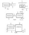
- FIG. 1Bis a chart showing the locations of the torque transmitting devices for the arrangement of planetary gear sets of the transmission shown in FIG. 1A , in accordance with the embodiments of the present invention.
- FIG. 2is a diagrammatic view of a transmission of the present invention in which the input and output shafts are provided on the same side of the transmission housing, in accordance with an embodiment of the present invention
- FIG. 3is a diagrammatic view of a one-way clutch connectable to the transmission of the present invention, in accordance with an embodiment of the present invention
- FIG. 4Ais a diagrammatic view of a transmission of the present invention coupled to a differential in a first arrangement, in accordance with an embodiment of the present invention
- FIG. 4Bis a diagrammatic view of a transmission of the present invention coupled to a differential in a second arrangement, in accordance with an embodiment of the present invention
- FIG. 5is a diagrammatic view of a drive motor and a coupling device connectable to the transmission of the present invention, in accordance with an embodiment of the present invention
- FIG. 6is a diagrammatic view of the powertrain of the present invention having a transmission arranged between a drive motor and a coupling device, in accordance with an embodiment of the present invention
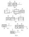
- FIG. 7is a diagrammatic view of the powertrain of the present invention having a vibrational damper arranged between a drive motor and a transmission, in accordance with an embodiment of the present invention
- FIG. 8is a diagrammatic view of a wear free brake connectable to the transmission of the present invention, in accordance with an embodiment of the present invention.
- FIG. 10is a diagrammatic view of an electric machine connectable to the transmission of the present invention, in accordance with an embodiment of the present invention.
- an embodiment of the present inventionincludes a multi-speed transmission 10 .
- the transmission 10is illustrated as a rear-wheel drive or longitudinal transmission, though various other types of transmission configurations may be employed.
- the transmission 10includes a transmission housing 11 , an input shaft or member 12 , and an output shaft or member 14 .
- the input member 12is continuously connected to an engine (not shown) or to a turbine of a torque converter (not shown).
- the output member 14is continuously connected with a final drive unit (not shown) or transfer case (not shown).
- the transmission 10includes a first planetary gear set 16 , a second planetary gear set 18 , a third planetary gear set 20 , and a fourth planetary gear set 22 .
- the planetary gear sets 16 , 18 , 20 and 22are connected between the input member 12 and the output member 14 .
- the planetary gear set 16includes a sun gear member 16 A, a ring gear member 16 C, and a planet carrier member 16 B that rotatably supports a set of planet or pinion gears 16 D (only one of which is shown).
- the pinion gears 16 Dare each configured to intermesh with both the sun gear member 16 A and the ring gear member 16 C.
- the sun gear member 16 Ais connected for common rotation with a first shaft or intermediate member 42 and a second shaft or intermediate member 44 . It should be appreciated that the first intermediate member 42 is connected for common rotation with the second intermediate member 44 and that the intermediate members 42 and 44 may form one single shaft or multiple shafts through one or more members of the planetary gear sets, as seen throughout the several views.
- the ring gear member 16 Cis connected for common rotation with a third shaft or intermediate member 46 .
- the planet carrier member 16 Bis connected for common rotation with a fourth shaft or intermediate member 48 .
- the planetary gear set 18includes a sun gear member 18 A, a ring gear member 18 C, and a planet carrier member 18 B that rotatably supports a set of planet or pinion gears 18 D.
- the pinion gears 18 Dare each configured to intermesh with both the sun gear member 18 A and the ring gear member 18 C.
- the sun gear member 18 Ais connected for common rotation with the second intermediate member 44 .
- the ring gear member 18 Cis connected for common rotation with a fifth shaft or intermediate member 50 .
- the planet carrier member 18 Bis connected for common rotation with the input member 12 .
- the planetary gear set 20includes a sun gear member 20 A, a ring gear member 20 C, and a carrier member 20 B that rotatably supports a set of planet or pinion gears 20 D.
- the pinion gears 20 Dare each configured to intermesh with both the sun gear member 20 A and the ring gear member 20 C.
- the sun gear member 20 Ais connected for common rotation with the fifth shaft or intermediate member 50 and with a sixth shaft or intermediate member 52 . It should be appreciated that the fifth intermediate member 50 is connected for common rotation with the sixth intermediate member 52 and that the intermediate members 50 and 52 may form one single shaft or multiple shafts through one or more members of the planetary gear sets, as seen throughout the several views.
- the ring gear member 20 Cis connected for common rotation with a seventh shaft or intermediate member 54 .
- the planet carrier member 20 Bis connected for common rotation with an eighth shaft or intermediate member 56 .
- the eighth intermediate member 56is connected for common rotation with the output member 14 and that the eighth intermediate members 56 and the output member 14 may form one single shaft or multiple shafts through one or more members of the planetary gear sets, as seen throughout the several views.
- the planetary gear set 22includes a sun gear member 22 A, a ring gear member 22 B, and a planet carrier member 22 B that rotatably supports a set of planet or pinion gears 22 D.
- the pinion gears 22 Dare each configured to intermesh with both the sun gear member 22 A and the ring gear member 22 C.
- the sun gear member 22 Ais connected for common rotation with a ninth shaft or intermediate member 58 and a tenth shaft or intermediate member 60 . It should be appreciated that the ninth intermediate member 58 is connected for common rotation with the tenth intermediate member 60 and that the intermediate members 58 and 60 may form one single shaft or multiple shafts through one or more members of the planetary gear sets, as seen throughout the several views.
- the ring gear member 22 Cis connected for common rotation with the fourth intermediate member 48 .
- the planet carrier member 22 Bis connected for common rotation with the output member 14 and with the eighth intermediate member 56 .
- the transmission 10includes a variety of torque-transmitting mechanisms or devices including a first clutch C 1 , a second clutch C 2 , a third clutch C 3 , a first brake B 1 and a second brake B 2 .
- the first clutch C 1is selectively engagable to connect the input member 12 to the tenth intermediate member 60 .
- the second clutch C 2is selectively engagable to connect the sixth intermediate member 52 to the ninth intermediate member 58 .
- the third intermediate clutch C 3is selectively engagable to connect the seventh intermediate member 54 to the ninth intermediate member 58 .
- the first brake B 1is selectively engagable to connect the first intermediate member 42 to the transmission housing 11 to restrict rotation of the first intermediate member 42 relative to the transmission housing 11 .
- the second brake B 2is selectively engagable to connect the third intermediate member 46 to the transmission housing 11 to restrict rotation of the third intermediate member 46 relative to the transmission housing 11 .
- the transmission 10is capable of transmitting torque from the input member 12 to the output member 14 in at least eight forward torque ratios and one reverse torque ratio.
- Each of the forward torque ratios and the reverse torque ratioare attained by engagement of one or more of the torque-transmitting mechanisms (i.e. first intermediate clutch C 1 , second intermediate clutch C 2 , third intermediate clutch C 3 , first brake B 1 and second brake B 2 ).
- first intermediate clutch C 1second intermediate clutch C 2
- third intermediate clutch C 3first brake B 1 and second brake B 2
- the transmission housing 11includes a first end wall 102 , a second end wall 104 , and a third wall 106 .
- the third wall 106interconnects between the first and second end walls 102 and 104 to provide a space or cavity 108 in which planetary gear sets 16 , 18 , 20 , and 22 and the torque-transmitting mechanisms C 1 , C 2 , C 3 , B 1 , and B 2 are located.
- the cavity 108has a plurality of areas or Zones A, B, C, D, E, and F in which the plurality of torque transmitting mechanisms C 1 , C 2 , C 3 , B 1 , and B 2 will be specifically positioned, in accordance with the preferred embodiments of the present invention.
- Zone Ais defined by the area or space bounded: axially on the left by the first end wall 102 , on the right by planetary gear set 16 , radially inward by a reference line “L” which is a longitudinal line that is axially aligned with the input shaft 12 , and radially outward by a reference line “M” which is a longitudinal line that extends adjacent an outer diameter or outer periphery of the planetary gear sets 16 , 18 , 20 , and 22 .
- Zone Bis defined by the area bounded: axially on the left by planetary gear set 16 , axially on the right by the planetary gear set 18 , radially outward by reference line “M”, and radially inward by reference line “L”.
- Zone Cis defined by the area bounded: axially on the left by the planetary gear set 18 , axially on the right by the planetary gear set 20 , radially outward by reference line “M”, and radially inward by reference line “L”.
- Zone Dis defined by the area bounded: axially on the left by the planetary gear set 20 , axially on the right by the planetary gear set 22 , radially outward by reference line “M”, and radially inward by reference line “L”.
- Zone Eis defined by the area bounded: axially on the left by the planetary gear set 22 , axially on the right by the second end wall 104 , radially outward by reference line “M”, and radially inward by reference line “L”.
- Zone Fis defined by the area bounded: axially on the left by the first end wall 102 , axially on the right by the second end wall 104 , radially inward by reference line “M” and radially outward by the third wall 106 .
- planetary gear sets 16 , 18 , 20 , and 22will change positions within the transmission cavity 108 , however, the Zones described above will not change and will remain the same as shown throughout the Figures.
- the planetary gear sets 16 , 18 , 20 , and 22are longitudinally arranged in the following order from left to right: 16 - 18 - 20 - 22 .
- the planetary gear set 16is disposed closest to the wall 102
- the planetary gear set 22is disposed closest to the wall 104
- the planetary gear set 18is adjacent the planetary gear set 16
- the planetary gear set 20is disposed between the planetary gear sets 18 and 22 .
- the torque-transmitting mechanismsare intentionally located within specific Zones in order to provide advantages in overall transmission size, packaging efficiency, and reduced manufacturing complexity.
- the torque-transmitting mechanism C 1is disposed within Zone C
- the torque-transmitting mechanisms C 2 and C 3are disposed within Zone D
- the torque-transmitting mechanisms B 1 and B 2are disposed within Zone F.
- the present inventioncontemplates other embodiments where the torque-transmitting mechanisms C 1 , C 2 , C 3 , B 1 , and B 2 are disposed in the other Zones.
- the feasible locations of the torque-transmitting devices C 1 , C 2 , C 3 , B 1 , and B 2 relative to the Zonesare illustrated in the chart shown in FIG. 1B .
- An “X” in the chartindicates that the present invention contemplates locating the particular torque-transmitting device in any of the referenced Zones.
- the first planetary gearset 16is the gearset of the transmission 10 nearest to the input shaft or member 12
- the fourth planetary gearset 22is the gearset nearest to the shaft or member 14 of the transmission.
- the input shaft or member 12 and the output shaft or member 14are arranged co-axially with respect to each other. It will be obvious to the person skilled in the art that this transmission can be modified without great effort so that the input and output shafts are no longer arranged co-axially with respect to each other, but as shown in FIG. 2 , axially parallel or at an angle with respect to each other.
- the person skilled in the artwill, if needed, arrange the drive of the transmission close to the fourth planetary gearset 22 , i.e., on the side of the fourth planetary gearset 22 that faces away from the planetary gearset 20 .
- the spatial arrangement of the torque-transmitting devices within the transmissionis optional in the embodiment of a multi-speed transmission, according to the invention shown in FIGS. 1A and 1B , and is limited only by the measurements and the external shape of the transmission housing.
- the present inventionprovides additional one-way clutches 120 at any suitable position in the multi-speed transmission 10 between a shaft or member 122 and the transmission housing 11 or in order to connect any two shafts or members, if necessary.
- An axle differential and/or a distributor differential 124can be arranged on either the input side or the output side of transmission 10 , as shown in FIGS. 4A and 4B .
- transmission 10may be arranged longitudinally within a vehicle and perpendicular with the axles 123 , as shown in FIG. 4A , or arranged transversely in the vehicle and parallel with the axles 125 , as shown in FIG. 4B .
- the input shaft or member 12can be separated, if needed, by a coupling device 126 of a drive motor 128 .
- the coupling device 124may be a torque converter, a hydraulic clutch, a dry starting clutch, a wet starting clutch, a magnetic particle clutch, or a centrifugal clutch.
- coupling device 126may be arranged within the powertrain behind the transmission 10 , where, in this case, the input shaft 12 is directly and permanently connected to the crankshaft 132 of the drive motor 128 .
- the multi-speed transmission 10provides the possibility of arranging a torsional vibration damper 134 between the drive motor 128 and the transmission 10 .
- a wear-free brake 136such as a hydraulic or electric retarder or the like can be arranged on the input shaft 12 or the output shaft 14 , which is particularly important for use in commercial vehicles.
- a power take-off 138can be provided on each shaft, as shown in FIG. 9 , preferably on the input shaft 12 or the output shaft 14 , in order to drive additional units 140 on each shaft.
- the torque-transmitting devices C 1 , C 2 , C 3 , B 1 , and B 2may be configured as power-shifting clutches or brakes.
- frictional clutches or brakessuch as disc clutches, band brakes and/or conical clutches, can be used.
- friction-based brakes and or/clutchessuch as synchronizers or claw clutches, can be used as torque-transmitting devices.
- a further advantage of the multi-speed transmission 10is that an electric machine or motor 150 can also be affixed to each shaft 12 , 14 as a generator and/or an additional drive unit.
Landscapes
- Engineering & Computer Science (AREA)
- General Engineering & Computer Science (AREA)
- Mechanical Engineering (AREA)
- Structure Of Transmissions (AREA)
Abstract
Description
Claims (25)
Priority Applications (3)
| Application Number | Priority Date | Filing Date | Title |
|---|---|---|---|
| US12/463,713US8292767B2 (en) | 2008-06-04 | 2009-05-11 | Powertrain having a multi-speed transmission |
| DE200910023562DE102009023562A1 (en) | 2008-06-04 | 2009-06-02 | Powertrain has clutches and brakes selectively engaged to establish eight forward speed ratios and one reverse speed ratio between transmission input and output sections |
| CN2009101460548ACN101596858B (en) | 2008-06-04 | 2009-06-03 | Powertrain having a multi-speed transmission |
Applications Claiming Priority (2)
| Application Number | Priority Date | Filing Date | Title |
|---|---|---|---|
| US5878108P | 2008-06-04 | 2008-06-04 | |
| US12/463,713US8292767B2 (en) | 2008-06-04 | 2009-05-11 | Powertrain having a multi-speed transmission |
Publications (2)
| Publication Number | Publication Date |
|---|---|
| US20090305838A1 US20090305838A1 (en) | 2009-12-10 |
| US8292767B2true US8292767B2 (en) | 2012-10-23 |
Family
ID=41400843
Family Applications (1)
| Application Number | Title | Priority Date | Filing Date |
|---|---|---|---|
| US12/463,713Expired - Fee RelatedUS8292767B2 (en) | 2008-06-04 | 2009-05-11 | Powertrain having a multi-speed transmission |
Country Status (2)
| Country | Link |
|---|---|
| US (1) | US8292767B2 (en) |
| CN (1) | CN101596858B (en) |
Cited By (2)
| Publication number | Priority date | Publication date | Assignee | Title |
|---|---|---|---|---|
| US11674565B2 (en) | 2019-10-07 | 2023-06-13 | Allison Transmission, Inc. | Multi-speed planetary transmission |
| US11867266B2 (en) | 2019-12-23 | 2024-01-09 | Allison Transmission, Inc. | Multi-speed planetary transmission |
Families Citing this family (17)
| Publication number | Priority date | Publication date | Assignee | Title |
|---|---|---|---|---|
| US7699741B2 (en)* | 2007-01-25 | 2010-04-20 | Gm Global Technology Operations, Inc. | Multi-speed transmission |
| US7775931B2 (en)* | 2007-03-16 | 2010-08-17 | Gm Global Technology Operations, Inc. | Multi-speed transmission |
| US8197378B2 (en)* | 2008-02-20 | 2012-06-12 | GM Global Technology Operations LLC | Multi-speed transaxle for a front wheel drive vehicle |
| US8123650B2 (en)* | 2008-02-20 | 2012-02-28 | GM Global Technology Operations LLC | Multi-speed transaxle for a front wheel drive vehicle |
| US8187138B2 (en)* | 2008-02-21 | 2012-05-29 | GM Global Technology Operations LLC | Multi-speed transaxle for a front wheel drive vehicle |
| US8267832B2 (en)* | 2008-04-16 | 2012-09-18 | GM Global Technology Operations LLC | Multi-speed transaxle |
| US7998015B2 (en)* | 2008-04-17 | 2011-08-16 | GM Global Technology Operations LLC | Multi-speed transaxle for a front wheel drive vehicle |
| US8206252B2 (en) | 2008-05-09 | 2012-06-26 | GM Global Technology Operations LLC | Hybrid powertrain having a multi-speed transmission |
| US8602934B2 (en)* | 2011-02-17 | 2013-12-10 | GM Global Technology Operations LLC | Multi-speed transmission with an integrated electric motor |
| DE102012212257A1 (en)* | 2011-09-27 | 2013-03-28 | Zf Friedrichshafen Ag | planetary gear |
| CA2861308C (en)* | 2012-02-28 | 2020-01-07 | Allison Transmission, Inc. | Multi-speed automatic transmission with fast reverse |
| US8649950B2 (en)* | 2012-04-11 | 2014-02-11 | Tai-Her Yang | Driving system having epicycle gear sets with dual output ends equipped with individually-controlled multiple speed-ratio device |
| CN102878258B (en)* | 2012-09-28 | 2015-05-13 | 邓亚民 | Planetary gear shift mechanism |
| CN102913597B (en)* | 2012-10-16 | 2015-04-15 | 中国北方车辆研究所 | Seven-level planet automatic speed changer |
| US8986155B2 (en)* | 2013-07-12 | 2015-03-24 | Ford Global Technolgies, Llc | Multi-speed transmission |
| CN109835155B (en)* | 2018-04-19 | 2023-08-29 | 广州市新域动力技术有限公司 | Star plate gear-shifting type automatic four-speed pure electric power assembly |
| US12000464B1 (en) | 2023-08-22 | 2024-06-04 | Allison Transmission, Inc. | Multi-speed planetary transmission |
Citations (21)
| Publication number | Priority date | Publication date | Assignee | Title |
|---|---|---|---|---|
| US6176803B1 (en) | 1999-09-28 | 2001-01-23 | Caterpillar Inc. | Transmission assembly with four planetary gear sets providing nine forward and one reverse gear ratio |
| US6558287B2 (en) | 2001-03-29 | 2003-05-06 | Aisin Aw Co., Ltd. | Automatic transmission for a vehicle |
| US20050090362A1 (en) | 2003-10-27 | 2005-04-28 | Toyota Jidosha Kabushiki Kaisha | Planetary-gear-type multiple-step transmission for vehicle |
| US6984187B2 (en) | 2001-03-30 | 2006-01-10 | Zf Friedrichshafen Ag | Multi-stage gearbox |
| US6991578B2 (en) | 2001-03-30 | 2006-01-31 | Zf Friedrichshafen Ag | Multistep gear |
| US7011597B2 (en) | 2004-03-24 | 2006-03-14 | General Motors Corporation | Multi-speed transmission |
| US7101305B2 (en) | 2003-05-27 | 2006-09-05 | Toyota Jidosha Kabushiki Kaisha | Planetary-gear-type multiple-step transmission for vehicle |
| US7115062B2 (en)* | 2004-09-28 | 2006-10-03 | General Motors Corporation | Multi-speed power transmission |
| US20060270513A1 (en) | 2005-05-25 | 2006-11-30 | Donald Klemen | Multi-speed transmission |
| US20060270516A1 (en) | 2005-05-25 | 2006-11-30 | Donald Klemen | Multi speed transmission |
| US7163484B2 (en) | 2005-01-24 | 2007-01-16 | General Motors Corporation | Eight-speed transmissions with four planetary gear sets |
| DE102005032001A1 (en) | 2005-07-08 | 2007-02-01 | Zf Friedrichshafen Ag | Multi-speed transmission |
| US20080011529A1 (en) | 2006-07-14 | 2008-01-17 | Zf Friedrichshafen Ag | Hybrid drive for a vehicle |
| US20080227587A1 (en) | 2007-03-16 | 2008-09-18 | Carey Clinton E | Multi-speed transmission |
| US20090209390A1 (en)* | 2008-02-20 | 2009-08-20 | Gm Global Technology Operations, Inc. | Multi-speed transaxle for a front wheel drive vehicle |
| US20090209391A1 (en)* | 2008-02-20 | 2009-08-20 | Gm Global Technology Operations, Inc. | Multi-speed transaxle for a front wheel drive vehicle |
| US20090264238A1 (en)* | 2008-04-17 | 2009-10-22 | Gm Global Technology Operations, Inc. | Multi-speed transaxle for a front wheel drive vehicle |
| US20090280941A1 (en) | 2008-05-09 | 2009-11-12 | Gm Global Technology Operations, Inc. | Hybrid powertrain having a multi-speed transmission |
| US7699741B2 (en)* | 2007-01-25 | 2010-04-20 | Gm Global Technology Operations, Inc. | Multi-speed transmission |
| US7736264B2 (en)* | 2007-06-08 | 2010-06-15 | Gm Global Technology Operations, Inc. | Eight speed automatic transmission with dual area clutch piston |
| US8012059B2 (en)* | 2007-05-30 | 2011-09-06 | GM Global Technology Operations LLC | Multi-speed automatic transmission |
Family Cites Families (3)
| Publication number | Priority date | Publication date | Assignee | Title |
|---|---|---|---|---|
| US6083135A (en)* | 1999-06-18 | 2000-07-04 | Ford Global Technologies, Inc. | Multiple speed overdrive transmission for a motor vehicle |
| US7354376B2 (en)* | 2005-12-07 | 2008-04-08 | Gm Global Technology Operations, Inc. | Multi speed transmission |
| CN100564941C (en)* | 2006-10-09 | 2009-12-02 | 通用汽车环球科技运作公司 | multi-speed transmission |
- 2009
- 2009-05-11USUS12/463,713patent/US8292767B2/ennot_activeExpired - Fee Related
- 2009-06-03CNCN2009101460548Apatent/CN101596858B/ennot_activeExpired - Fee Related
Patent Citations (23)
| Publication number | Priority date | Publication date | Assignee | Title |
|---|---|---|---|---|
| US6176803B1 (en) | 1999-09-28 | 2001-01-23 | Caterpillar Inc. | Transmission assembly with four planetary gear sets providing nine forward and one reverse gear ratio |
| US6558287B2 (en) | 2001-03-29 | 2003-05-06 | Aisin Aw Co., Ltd. | Automatic transmission for a vehicle |
| US6984187B2 (en) | 2001-03-30 | 2006-01-10 | Zf Friedrichshafen Ag | Multi-stage gearbox |
| US6991578B2 (en) | 2001-03-30 | 2006-01-31 | Zf Friedrichshafen Ag | Multistep gear |
| US7018319B2 (en) | 2001-03-30 | 2006-03-28 | Zf Friedrichshafen Ag | Multistep gear |
| US7101305B2 (en) | 2003-05-27 | 2006-09-05 | Toyota Jidosha Kabushiki Kaisha | Planetary-gear-type multiple-step transmission for vehicle |
| US20050090362A1 (en) | 2003-10-27 | 2005-04-28 | Toyota Jidosha Kabushiki Kaisha | Planetary-gear-type multiple-step transmission for vehicle |
| US7011597B2 (en) | 2004-03-24 | 2006-03-14 | General Motors Corporation | Multi-speed transmission |
| US7115062B2 (en)* | 2004-09-28 | 2006-10-03 | General Motors Corporation | Multi-speed power transmission |
| US7163484B2 (en) | 2005-01-24 | 2007-01-16 | General Motors Corporation | Eight-speed transmissions with four planetary gear sets |
| US20060270516A1 (en) | 2005-05-25 | 2006-11-30 | Donald Klemen | Multi speed transmission |
| US20060270513A1 (en) | 2005-05-25 | 2006-11-30 | Donald Klemen | Multi-speed transmission |
| DE102005032001A1 (en) | 2005-07-08 | 2007-02-01 | Zf Friedrichshafen Ag | Multi-speed transmission |
| US20080011529A1 (en) | 2006-07-14 | 2008-01-17 | Zf Friedrichshafen Ag | Hybrid drive for a vehicle |
| US7699741B2 (en)* | 2007-01-25 | 2010-04-20 | Gm Global Technology Operations, Inc. | Multi-speed transmission |
| US20080227587A1 (en) | 2007-03-16 | 2008-09-18 | Carey Clinton E | Multi-speed transmission |
| US7775931B2 (en)* | 2007-03-16 | 2010-08-17 | Gm Global Technology Operations, Inc. | Multi-speed transmission |
| US8012059B2 (en)* | 2007-05-30 | 2011-09-06 | GM Global Technology Operations LLC | Multi-speed automatic transmission |
| US7736264B2 (en)* | 2007-06-08 | 2010-06-15 | Gm Global Technology Operations, Inc. | Eight speed automatic transmission with dual area clutch piston |
| US20090209390A1 (en)* | 2008-02-20 | 2009-08-20 | Gm Global Technology Operations, Inc. | Multi-speed transaxle for a front wheel drive vehicle |
| US20090209391A1 (en)* | 2008-02-20 | 2009-08-20 | Gm Global Technology Operations, Inc. | Multi-speed transaxle for a front wheel drive vehicle |
| US20090264238A1 (en)* | 2008-04-17 | 2009-10-22 | Gm Global Technology Operations, Inc. | Multi-speed transaxle for a front wheel drive vehicle |
| US20090280941A1 (en) | 2008-05-09 | 2009-11-12 | Gm Global Technology Operations, Inc. | Hybrid powertrain having a multi-speed transmission |
Cited By (3)
| Publication number | Priority date | Publication date | Assignee | Title |
|---|---|---|---|---|
| US11674565B2 (en) | 2019-10-07 | 2023-06-13 | Allison Transmission, Inc. | Multi-speed planetary transmission |
| US12228194B2 (en) | 2019-10-07 | 2025-02-18 | Allison Transmission, Inc. | Multi-speed planetary transmission |
| US11867266B2 (en) | 2019-12-23 | 2024-01-09 | Allison Transmission, Inc. | Multi-speed planetary transmission |
Also Published As
| Publication number | Publication date |
|---|---|
| CN101596858B (en) | 2013-04-24 |
| US20090305838A1 (en) | 2009-12-10 |
| CN101596858A (en) | 2009-12-09 |
Similar Documents
| Publication | Publication Date | Title |
|---|---|---|
| US8292767B2 (en) | Powertrain having a multi-speed transmission | |
| US8197378B2 (en) | Multi-speed transaxle for a front wheel drive vehicle | |
| US8123651B2 (en) | Multi-speed transaxle for a front wheel drive vehicle | |
| US7998015B2 (en) | Multi-speed transaxle for a front wheel drive vehicle | |
| US8123650B2 (en) | Multi-speed transaxle for a front wheel drive vehicle | |
| US8267832B2 (en) | Multi-speed transaxle | |
| US8187138B2 (en) | Multi-speed transaxle for a front wheel drive vehicle | |
| US8192320B2 (en) | Multi-speed transaxle | |
| US8167767B2 (en) | Multi-speed transaxle | |
| US8403804B2 (en) | Multi-speed transaxle | |
| US8118700B2 (en) | Multi-speed transmission for a front wheel drive vehicle | |
| US8157696B2 (en) | Multi-speed transaxle for a front wheel drive vehicle | |
| US8202194B2 (en) | Clutch and gear arrangement for a front wheel drive vehicle | |
| US9052003B2 (en) | Multi-speed transmission gear and clutch arrangement | |
| US8123652B2 (en) | Multi-speed transaxle for a front wheel drive vehicle | |
| US8241167B2 (en) | Multi-speed transaxle | |
| US8465389B2 (en) | Clutch and gear arrangement for a front wheel drive vehicle | |
| US20130203542A1 (en) | Multi-speed transmission gear and clutch arrangement | |
| US7273438B2 (en) | Automatic transmission | |
| US8177676B2 (en) | Multi-speed transaxle | |
| US8025605B2 (en) | Multi-speed transmission for a front wheel drive vehicle |
Legal Events
| Date | Code | Title | Description |
|---|---|---|---|
| AS | Assignment | Owner name:GM GLOBAL TECHNOLOGY OPERATIONS, INC., MICHIGAN Free format text:ASSIGNMENT OF ASSIGNORS INTEREST;ASSIGNORS:BORGERSON, JAMES B.;DUSENBERRY, DONALD L.;PHILLIPS, ANDREW W.;AND OTHERS;REEL/FRAME:022669/0897;SIGNING DATES FROM 20090506 TO 20090511 Owner name:GM GLOBAL TECHNOLOGY OPERATIONS, INC., MICHIGAN Free format text:ASSIGNMENT OF ASSIGNORS INTEREST;ASSIGNORS:BORGERSON, JAMES B.;DUSENBERRY, DONALD L.;PHILLIPS, ANDREW W.;AND OTHERS;SIGNING DATES FROM 20090506 TO 20090511;REEL/FRAME:022669/0897 | |
| AS | Assignment | Owner name:UNITED STATES DEPARTMENT OF THE TREASURY,DISTRICT Free format text:SECURITY AGREEMENT;ASSIGNOR:GM GLOBAL TECHNOLOGY OPERATIONS, INC.;REEL/FRAME:023201/0118 Effective date:20090710 Owner name:UNITED STATES DEPARTMENT OF THE TREASURY, DISTRICT Free format text:SECURITY AGREEMENT;ASSIGNOR:GM GLOBAL TECHNOLOGY OPERATIONS, INC.;REEL/FRAME:023201/0118 Effective date:20090710 | |
| AS | Assignment | Owner name:UAW RETIREE MEDICAL BENEFITS TRUST,MICHIGAN Free format text:SECURITY AGREEMENT;ASSIGNOR:GM GLOBAL TECHNOLOGY OPERATIONS, INC.;REEL/FRAME:023162/0048 Effective date:20090710 Owner name:UAW RETIREE MEDICAL BENEFITS TRUST, MICHIGAN Free format text:SECURITY AGREEMENT;ASSIGNOR:GM GLOBAL TECHNOLOGY OPERATIONS, INC.;REEL/FRAME:023162/0048 Effective date:20090710 | |
| AS | Assignment | Owner name:GM GLOBAL TECHNOLOGY OPERATIONS, INC., MICHIGAN Free format text:RELEASE BY SECURED PARTY;ASSIGNOR:UNITED STATES DEPARTMENT OF THE TREASURY;REEL/FRAME:025246/0056 Effective date:20100420 | |
| AS | Assignment | Owner name:GM GLOBAL TECHNOLOGY OPERATIONS, INC., MICHIGAN Free format text:RELEASE BY SECURED PARTY;ASSIGNOR:UAW RETIREE MEDICAL BENEFITS TRUST;REEL/FRAME:025315/0091 Effective date:20101026 | |
| AS | Assignment | Owner name:WILMINGTON TRUST COMPANY, DELAWARE Free format text:SECURITY AGREEMENT;ASSIGNOR:GM GLOBAL TECHNOLOGY OPERATIONS, INC.;REEL/FRAME:025324/0555 Effective date:20101027 | |
| AS | Assignment | Owner name:GM GLOBAL TECHNOLOGY OPERATIONS LLC, MICHIGAN Free format text:CHANGE OF NAME;ASSIGNOR:GM GLOBAL TECHNOLOGY OPERATIONS, INC.;REEL/FRAME:025781/0299 Effective date:20101202 | |
| FEPP | Fee payment procedure | Free format text:PAYOR NUMBER ASSIGNED (ORIGINAL EVENT CODE: ASPN); ENTITY STATUS OF PATENT OWNER: LARGE ENTITY | |
| STCF | Information on status: patent grant | Free format text:PATENTED CASE | |
| AS | Assignment | Owner name:GM GLOBAL TECHNOLOGY OPERATIONS LLC, MICHIGAN Free format text:RELEASE BY SECURED PARTY;ASSIGNOR:WILMINGTON TRUST COMPANY;REEL/FRAME:034185/0789 Effective date:20141017 | |
| FPAY | Fee payment | Year of fee payment:4 | |
| FEPP | Fee payment procedure | Free format text:MAINTENANCE FEE REMINDER MAILED (ORIGINAL EVENT CODE: REM.); ENTITY STATUS OF PATENT OWNER: LARGE ENTITY | |
| LAPS | Lapse for failure to pay maintenance fees | Free format text:PATENT EXPIRED FOR FAILURE TO PAY MAINTENANCE FEES (ORIGINAL EVENT CODE: EXP.); ENTITY STATUS OF PATENT OWNER: LARGE ENTITY | |
| STCH | Information on status: patent discontinuation | Free format text:PATENT EXPIRED DUE TO NONPAYMENT OF MAINTENANCE FEES UNDER 37 CFR 1.362 | |
| FP | Lapsed due to failure to pay maintenance fee | Effective date:20201023 |