US8292461B2 - Heatsink for cooling at least one LED - Google Patents
Heatsink for cooling at least one LEDDownload PDFInfo
- Publication number
- US8292461B2 US8292461B2US13/367,396US201213367396AUS8292461B2US 8292461 B2US8292461 B2US 8292461B2US 201213367396 AUS201213367396 AUS 201213367396AUS 8292461 B2US8292461 B2US 8292461B2
- Authority
- US
- United States
- Prior art keywords
- led
- heatsink
- elongated
- panel
- partially arcuate
- Prior art date
- Legal status (The legal status is an assumption and is not a legal conclusion. Google has not performed a legal analysis and makes no representation as to the accuracy of the status listed.)
- Expired - Fee Related
Links
- 238000001816coolingMethods0.000titleclaimsabstractdescription10
- 229910000838Al alloyInorganic materials0.000description4
- 239000000463materialSubstances0.000description4
- 238000004891communicationMethods0.000description3
- 230000008878couplingEffects0.000description3
- 238000010168coupling processMethods0.000description3
- 238000005859coupling reactionMethods0.000description3
- 229920001296polysiloxanePolymers0.000description3
- AZDRQVAHHNSJOQ-UHFFFAOYSA-NalumaneChemical class[AlH3]AZDRQVAHHNSJOQ-UHFFFAOYSA-N0.000description2
- 229910052782aluminiumInorganic materials0.000description2
- XAGFODPZIPBFFR-UHFFFAOYSA-NaluminiumChemical compound[Al]XAGFODPZIPBFFR-UHFFFAOYSA-N0.000description2
- 229910052751metalInorganic materials0.000description2
- 239000002184metalSubstances0.000description2
- 238000000034methodMethods0.000description2
- 238000012986modificationMethods0.000description2
- 230000004048modificationEffects0.000description2
- 238000012797qualificationMethods0.000description2
- 238000005266castingMethods0.000description1
- 238000010276constructionMethods0.000description1
- 239000011521glassSubstances0.000description1
- 239000004519greaseSubstances0.000description1
- 230000017525heat dissipationEffects0.000description1
- 238000009434installationMethods0.000description1
- 229910001507metal halideInorganic materials0.000description1
- 150000005309metal halidesChemical class0.000description1
- 230000003287optical effectEffects0.000description1
- 230000009103reabsorptionEffects0.000description1
- 230000000717retained effectEffects0.000description1
- 239000004576sandSubstances0.000description1
- 239000000565sealantSubstances0.000description1
Images


Classifications
- F—MECHANICAL ENGINEERING; LIGHTING; HEATING; WEAPONS; BLASTING
- F21—LIGHTING
- F21S—NON-PORTABLE LIGHTING DEVICES; SYSTEMS THEREOF; VEHICLE LIGHTING DEVICES SPECIALLY ADAPTED FOR VEHICLE EXTERIORS
- F21S8/00—Lighting devices intended for fixed installation
- F21S8/08—Lighting devices intended for fixed installation with a standard
- F21S8/085—Lighting devices intended for fixed installation with a standard of high-built type, e.g. street light
- F21S8/088—Lighting devices intended for fixed installation with a standard of high-built type, e.g. street light with lighting device mounted on top of the standard, e.g. for pedestrian zones
- F—MECHANICAL ENGINEERING; LIGHTING; HEATING; WEAPONS; BLASTING
- F21—LIGHTING
- F21V—FUNCTIONAL FEATURES OR DETAILS OF LIGHTING DEVICES OR SYSTEMS THEREOF; STRUCTURAL COMBINATIONS OF LIGHTING DEVICES WITH OTHER ARTICLES, NOT OTHERWISE PROVIDED FOR
- F21V29/00—Protecting lighting devices from thermal damage; Cooling or heating arrangements specially adapted for lighting devices or systems
- F21V29/50—Cooling arrangements
- F21V29/70—Cooling arrangements characterised by passive heat-dissipating elements, e.g. heat-sinks
- F21V29/83—Cooling arrangements characterised by passive heat-dissipating elements, e.g. heat-sinks the elements having apertures, ducts or channels, e.g. heat radiation holes
- F—MECHANICAL ENGINEERING; LIGHTING; HEATING; WEAPONS; BLASTING
- F21—LIGHTING
- F21Y—INDEXING SCHEME ASSOCIATED WITH SUBCLASSES F21K, F21L, F21S and F21V, RELATING TO THE FORM OR THE KIND OF THE LIGHT SOURCES OR OF THE COLOUR OF THE LIGHT EMITTED
- F21Y2107/00—Light sources with three-dimensionally disposed light-generating elements
- F21Y2107/30—Light sources with three-dimensionally disposed light-generating elements on the outer surface of cylindrical surfaces, e.g. rod-shaped supports having a circular or a polygonal cross section
- F—MECHANICAL ENGINEERING; LIGHTING; HEATING; WEAPONS; BLASTING
- F21—LIGHTING
- F21Y—INDEXING SCHEME ASSOCIATED WITH SUBCLASSES F21K, F21L, F21S and F21V, RELATING TO THE FORM OR THE KIND OF THE LIGHT SOURCES OR OF THE COLOUR OF THE LIGHT EMITTED
- F21Y2115/00—Light-generating elements of semiconductor light sources
- F21Y2115/10—Light-emitting diodes [LED]
- Y—GENERAL TAGGING OF NEW TECHNOLOGICAL DEVELOPMENTS; GENERAL TAGGING OF CROSS-SECTIONAL TECHNOLOGIES SPANNING OVER SEVERAL SECTIONS OF THE IPC; TECHNICAL SUBJECTS COVERED BY FORMER USPC CROSS-REFERENCE ART COLLECTIONS [XRACs] AND DIGESTS
- Y10—TECHNICAL SUBJECTS COVERED BY FORMER USPC
- Y10S—TECHNICAL SUBJECTS COVERED BY FORMER USPC CROSS-REFERENCE ART COLLECTIONS [XRACs] AND DIGESTS
- Y10S362/00—Illumination
- Y10S362/80—Light emitting diode
Definitions
- This inventionpertains to a heatsink for cooling at least one LED.
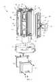
- FIG. 1is a top perspective view showing a first embodiment of a LED unit installed in a post-top luminaire, with a globe of the post-top luminaire exploded away.
- FIG. 3is an exploded perspective view of the LED unit of FIG. 1 .
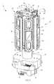
- FIG. 4is a perspective view of the LED unit of FIG. 1 showing two LED panels individually rotated about their respective vertical panel axes.
- FIG. 6is a top perspective view showing a second embodiment of a LED unit with an embodiment of an LED panel exploded away.
- FIG. 7is a perspective view of a heatsink of the LED panel of the LED unit of FIG. 6 .
- LED unit 10is shown installed in a post-top luminaire.
- the post-top luminaireincludes a support base or pole 6 which is coupled to and supports a fitter 4 .
- the fitter 4supports a globe 2 , shown in FIG. 1 exploded away from fitter 4 .
- the globe 2may be sealably retained by fitter 4 , forming an optical chamber substantially sealed from the external environment.
- Globe 2may be designed to help achieve a given light distribution pattern and may be provided with a refractive surface, prismatic surface, and/or reflectors, among other items, if desired for a particular light distribution.
- LED unit 10may be used with or adapted for use with a variety of post-top luminaires having varied support, fitter, and/or globe configurations, among other things.
- globe 2may include a separable roof portion. The roof portion may be removably sealed to the globe and the globe may be removably or fixedly sealed to the fitter 4 .
- LED unit 10has an LED driver cover 72 that may be removably affixed to the fitter 4 and that may cover at least one LED driver 74 .
- Six vertically oriented elongated LED panels 40are disposed above the LED driver cover 72 and are arranged in a generally circular fashion about a central open region. The central open region may be used for wiring to make appropriate electrical connections to each LED panel 40 and/or may provide an area for more efficient cooling.
- Each LED panel 40is disposed between a top portion 22 and a bottom portion 26 of a frame. Top portion 22 and bottom portion 26 each have a central hub with support structure or six spokes extending therefrom.
- Each LED panel 40is held in place by screws 23 that are inserted through apertures in support structure of top portion 22 and bottom portion 26 of the frame and received in a corresponding receptacle 41 of each LED panel 40 .
- the screws 23 associated with any one LED panel 40may be loosened to allow for rotational movement of each LED panel 40 about a vertical panel axis.
- the screws 23may also be tightened to fix each LED panel 40 at a given rotational orientation about its respective vertical panel axis.
- LED unit 10may be used in retrofit applications if desired and LED panels 40 may be appropriately rotated to replicate a previously existing distribution pattern, or create a new distribution pattern, while interfacing with the same preexisting globe of the post-top luminaire.
- LED unit 10may be used to replace an incandescent light source or a metal halide light source.
- Screws 23 associated with any one LED panel 40may also be loosened and completely removed to allow for detachment of any LED panel 40 .
- three LED panels 40have been detached and removed from LED unit 10 .
- One or more LED panels 40may be removed to alter the distribution pattern and/or luminous intensity of LED unit 10 and may be removed by a user or at the factory.
- the ability to rotate each LED panel 40 about its respective vertical panel axis and to selectively detach and remove each LED panelprovides an easily customizable LED unit 10 providing for flexibility in light distribution and luminosity.
- each LED panel 40may be used in some embodiments to rotatably and/or removably attach each LED panel 40 to top portion 22 and/or bottom portion 26 of the frame.
- prongs and/or structure extending from top portion 22 and/or bottom portion 26 of the framemay interface with corresponding structure on LED panels 40 .
- this interchangeablyincludes fasteners and/or structure extending from LED panels 40 that correspond with structure on top portion 22 and/or bottom portion 26 of the frame.
- the frame of the first embodimenthas been described as having both a top frame portion 22 and a bottom frame portion 26 with specific structure, one skilled in the art will recognize that other frame configurations may properly support LED panels 40 , including frames that only have a bottom frame portion 26 or only have a top frame portion 22 .
- Each LED panel 40 shownhas a support surface with three recessed pockets 42 .
- at least one LED printed circuit boardsuch as LED printed circuit board 44
- LED printed circuit board 44may be received in each recessed pocket 42 and secured in recessed pocket by, for example, screws 45 .
- LED printed circuit board 44may be a metal core circuit board and have seven or ten one-watt Luxeon Rebel LEDs coupled thereto. In alternative configurations differing numbers of LEDs may be used as well as printed circuit boards of differing material.
- a thermal interface materialmay optionally be interposed between LED printed circuit board 44 and the support surface of the LED panel 40 .
- the thermal interface materialmay include a thermal pad such as an eGRAF HITHERM HT-1220 thermal pad manufactured GrafTech.
- thermal interface materialsmay optionally be used such as, but not limited to, thermal grease or thermal paste.
- a lens 46may then be placed over LED printed circuit board 44 and seal each recessed pocket 42 in such a manner as to achieve appropriate ingress protection rating qualifications if desired.
- each lens 46may be affixed using a high temperature silicone and achieve an ingress protection rating of IP 66 .
- the high temperature siliconemay be Dow Corning 733 Glass and Metal Sealant.
- Aperturesmay also be provided through portions of LED panel 40 to enable wiring to extend from LED driver 74 to any LED printed circuit board 44 . Such apertures may likewise be sealed with high temperature silicone to achieve appropriate ingress rating qualifications.
- recessed pockets 42may be provided with a LED printed circuit board. This allows for a manufacturer and/or user to use the same LED panel 40 with a variable amount of LED printed circuit boards 44 in order to provide flexibility in luminous output and/or light distribution from LED unit 10 .
- a manufacturer and/or usermay use the same LED panel 40 with a variable amount of LED printed circuit boards 44 in order to provide flexibility in luminous output and/or light distribution from LED unit 10 .
- only one recessed site 42may be provided with a LED printed circuit board 44 and covered with a lens 46 .
- each recessed site 42may be provided with a LED printed circuit board and covered with a lens 46 , providing for a higher luminosity LED unit 10 .
- each support surface of each LED panel 40Extending rearward from each support surface of each LED panel 40 is a heatsink 48 having a plurality of variable height heat fins that extend rearward and away from the support surface of LED panel 40 .
- LED support surface and LED heatsink 48are formed as an integral piece, which can be made, for example, by a casting from aluminum or an aluminum alloy such as a 356 Hadco Modified aluminum alloy.
- Heatsink 48is in thermal connectivity with recessed sites 42 and any LED printed circuit boards 44 received by recessed sites 42 and helps dissipate heat generated by any LED printed circuit board 44 .
- a frame support base 76may support bottom frame portion 26 and is coupled to LED driver cover 72 , which covers a pair of LED drivers 74 . In other embodiments only one LED driver, or more than two LED drivers may be provided. Frame support base 76 may be interchanged at the factory or by a user with a frame support base of a differing height to permit vertical adjustment of the LED panels 40 in order to appropriately position LED unit 10 within a globe of a particular post-top luminaire.
- the depicted LED driver cover 72is a Twistlock ballast cover manufactured by Hadco from die cast aluminum and is designed to rotatably engage corresponding structure extending from the top of a fitter of a post-top luminaire and be locked in place with a spring clip.
- LED driver cover 72 and LED unit 10provide for tool-less installation of LED unit 10 .
- other driver coversmay be utilized to appropriately isolate LED drivers, such as LED drivers 74 .
- LED drivers 74may be placed in electrical communication with one another and contain a terminal block 75 for electrically coupling LED drivers 74 with power from a power source.
- LED drivers 74may be one or more drivers manufactured by Advance, part number LED120A0024V10F.
- a second embodiment of an LED unit 100has an LED driver cover 172 that covers an elongated single LED driver 174 .
- Six vertically oriented LED panels 140are disposed above the LED driver cover 172 and are arranged in a generally circular fashion about a central open region. The central open region may be used for wiring to make appropriate electrical connections to each LED panel 140 and/or may provide an area for more efficient cooling.
- Each LED panel 140is disposed between a top portion 122 and a bottom portion 126 of a frame. Top portion 122 and bottom portion 126 each have a central hub with support structure or six interconnected spokes extending therefrom.
- Each LED panel 140is held in place by screws 123 that are each inserted through an aperture in part of the support structure interconnecting each spoke of top portion 122 and bottom portion 126 of the frame and received in a receptacle 141 of each LED panel 140 .
- the screws 123 associated with any one LED panel 140may be loosened to allow for rotational movement of each LED panel 140 about a vertical panel axis.
- the screws 123may also be tightened to fix each LED panel 140 at a given rotational orientation about its respective vertical panel axis. Screws 123 associated with any one LED panel 140 may also be loosened and completely removed to allow for detachment of any LED panel 140 .
- Each LED panel 140has a support surface with three recessed pockets 142 . At least one LED printed circuit board may be received and secured in each recessed pocket 142 . A lens 146 may then be installed to seal each recessed pocket 142 . Extending rearward from each support surface of each LED panel 140 is a heatsink 148 having a plurality of arcuate heat fins in thermal connectivity with a support surface having recessed sites 142 and any LED printed circuit boards received by recessed sites 142 and helps dissipate heat generated by the LEDs of the LED printed circuit board.
- Heatsink 148has a plurality of arcuate heat fins 154 a - e , 155 a - e , 164 a - e , and 165 a - e flanking each side of a channel 156 that extends longitudinally along the entire length of heatsink 148 .
- LED heatsink 148may be sand casted from an aluminum alloy such as a 356 Hadco Modified aluminum alloy.
- channel 156is centrally aligned and includes bosses 157 , 158 , 159 , 167 , 168 , and 169 that extend partially into channel 156 .
- Bosses 157 , 158 , 159 , 167 , 168 , and 169may receive corresponding screws or other fasteners that are used to secure printed circuit boards within recessed sites 142 .
- Fasteners that are used to secure printed circuit boards within recessed sites 142may also or alternatively be received in bosses that are completely or partially within any or all of arcuate heat fins 154 a - e , 155 a - e , 164 a - e , and 165 a - e.
- the arcuate heat fins 154 a - e , 155 a - e , 164 a - e , and 165 a - eextend from proximal central channel 156 toward the longitudinal periphery of heatsink 148 and are oriented to efficiently dissipate heat from heatsink 148 when heatsink 148 is oriented vertically, horizontally, or at an angle between horizontal and vertical.
- Each arcuate heat fin 154 a - e , 155 a - e , 164 a - e , and 165 a - ehas a first end located proximal central channel 156 and a second end located proximal a trough adjacent a ridge 172 that extends longitudinally proximal the longitudinal periphery of the heatsink 148 .
- Heatsink 148may be divided latitudinally into a first portion and a second portion in some embodiments.
- pie shaped heat fins 160 and 161divide heatsink 148 into a first and second portion and define a latitudinal dividing region.
- Each arcuate heat fin 154 a - e , 155 a - e , 164 a - e , and 165 a - eis oriented such that the interior face of each arcuate heat fin 154 a - e , 155 a - e , 164 a - e , and 165 a - e generally faces toward the dividing region generally defined by pie shaped heat fins 160 and 161 and generally faces away from channel 156 .
- each arcuate heat fin 154 a - e , 155 a - e , 164 a - e , and 165 a - eis more distal the dividing region and channel 156 than the first end of each arcuate heat fin and the exterior face of each arcuate heat fin generally faces toward channel 156 .
- the amount of heat that becomes trapped in between the heat fins and reabsorbedis reduced.
- heatsink 148When oriented in a non-horizontal direction, heat dissipation is further optimized by heatsink 148 as a result of natural convection. For example, assuming heat fins 152 and 153 are located at a higher vertical position than heat fins 162 and 163 , hot air, exemplarily designated by Arrows H in FIG. 8 , is forced outward and away from heatsink 148 . Cooling air, exemplarily designated by Arrows C in FIG. 8 , is drawn toward the heatsink from the surrounding environment. Central channel 156 provides a path for communication of air between heat fins, exemplarily designated by the unlabeled arrows extending through central channel 156 , and further aids in heat removal and natural convection.
- the shape and orientation of the heat fins in the depicted embodimentaids natural convection by forcing heat outward and away from heatsink 148 while drawing in cooling air and reduces reabsorption of heat by the heat fins of heatsink 148 .
- the shape of the heat finsalso provides additional surface area for improved convection.
- an apparatussuch as a fan may be used in conjunction with heatsink 148 for forced convection.
- each arcuate heat fin 154 a - e , 155 a - e , 164 a - e , and 165 a - eis a curved segment of a circle and has a corresponding arcuate heat fin that also forms a curved segment of the same circle.
- each arcuate heat fin 154 a - e , 155 a - e , 164 a - e , and 165 a - ehas a mirror imaged heat fin located on the opposite side of channel 156 that also has a corresponding arcuate heat fin that also forms a segment of the same circle.
- arcuate heat fins 155 a and 165 aform a segment of the same circle and may generally circulate air between one another, potentially increasing the convective current.
- arcuate heat fins 155 a and 165 aare arcuate heat fins 154 a and 164 a , which form a segment of a circle that is the same radius of the segment of the circle formed by arcuate heat fins 155 a and 165 a .
- arcuate heat fins 155 e and 165 eform a segment of the same circle, which is much larger than the circle partially formed by arcuate heat fins 155 a and 165 a .
- arcuate heat fins 155 e and 165 ehave a more gradual curvature than arcuate heat fins 155 a and 165 a.
- heatsink 148the curvature of heat fins 154 a - e , 155 a - e , 164 a - e , and 165 a - e becomes more gradual the farther away from pie shaped heat fins 160 and 161 it is located, such that each heat fin progressively forms a segment of a larger circle.
- Heat fins 152 , 153 , 162 , and 163are not segments of a circle, but do aid in the convective process and help dissipate heat away from, and draw cooling air into, heatsink 148 .
- arcuate heat fins 152 , 153 , 162 , and 163is formed from two nearly linear portions, it still has a generally arcuate overall shape. Extending along the longitudinal peripheries of heatsink 148 is a ridge portion 172 , which sits atop a trough and may be provided for additional surface area for dissipation of heat.
- heatsink 148has been illustrated and described in detail, it should not be limited to the precise forms disclosed and obviously many modifications and variations to heatsink 148 are possible in light of the teachings herein.
- some or all arcuate heat finsmay not form a segment of a circle, but may instead be otherwise arcuate.
- some or all arcuate heat finsmay not be provided with a corresponding mirror imaged heat fin on an opposite side of a channel and/or an opposite side of a dividing region.
- the dividing regionmay not have any heat fins such as pie shaped heat fins 160 and 161 .
- heat finsmay have one or more faces formed from multiple linear segments and still be generally arcuate in shape.
- heatsink 148has been illustrated and described, it is not limited thereto except insofar as such limitations are included in the following claims and allowable functional equivalents thereof. Also, although heatsink 148 has been described in conjunction with a LED unit 100 , one skilled in the art will readily recognize its uses are not limited to such.
Landscapes
- Engineering & Computer Science (AREA)
- General Engineering & Computer Science (AREA)
- Arrangement Of Elements, Cooling, Sealing, Or The Like Of Lighting Devices (AREA)
- Non-Portable Lighting Devices Or Systems Thereof (AREA)
Abstract
Description
Claims (10)
Priority Applications (1)
| Application Number | Priority Date | Filing Date | Title |
|---|---|---|---|
| US13/367,396US8292461B2 (en) | 2009-05-15 | 2012-02-07 | Heatsink for cooling at least one LED |
Applications Claiming Priority (2)
| Application Number | Priority Date | Filing Date | Title |
|---|---|---|---|
| US12/467,062US8123378B1 (en) | 2009-05-15 | 2009-05-15 | Heatsink for cooling at least one LED |
| US13/367,396US8292461B2 (en) | 2009-05-15 | 2012-02-07 | Heatsink for cooling at least one LED |
Related Parent Applications (1)
| Application Number | Title | Priority Date | Filing Date |
|---|---|---|---|
| US12/467,062ContinuationUS8123378B1 (en) | 2009-05-15 | 2009-05-15 | Heatsink for cooling at least one LED |
Publications (2)
| Publication Number | Publication Date |
|---|---|
| US20120134145A1 US20120134145A1 (en) | 2012-05-31 |
| US8292461B2true US8292461B2 (en) | 2012-10-23 |
Family
ID=45694408
Family Applications (2)
| Application Number | Title | Priority Date | Filing Date |
|---|---|---|---|
| US12/467,062Active2030-01-21US8123378B1 (en) | 2009-05-15 | 2009-05-15 | Heatsink for cooling at least one LED |
| US13/367,396Expired - Fee RelatedUS8292461B2 (en) | 2009-05-15 | 2012-02-07 | Heatsink for cooling at least one LED |
Family Applications Before (1)
| Application Number | Title | Priority Date | Filing Date |
|---|---|---|---|
| US12/467,062Active2030-01-21US8123378B1 (en) | 2009-05-15 | 2009-05-15 | Heatsink for cooling at least one LED |
Country Status (1)
| Country | Link |
|---|---|
| US (2) | US8123378B1 (en) |
Cited By (3)
| Publication number | Priority date | Publication date | Assignee | Title |
|---|---|---|---|---|
| US20110073883A1 (en)* | 2008-05-29 | 2011-03-31 | Rohm Co., Ltd. | Led lamp |
| US20110089390A1 (en)* | 2009-10-16 | 2011-04-21 | Steinkraus Thomas F | Post mount for lighted handrail assembly |
| US20140270731A1 (en)* | 2013-03-12 | 2014-09-18 | Applied Materials, Inc. | Thermal management apparatus for solid state light source arrays |
Families Citing this family (27)
| Publication number | Priority date | Publication date | Assignee | Title |
|---|---|---|---|---|
| US8680754B2 (en)* | 2008-01-15 | 2014-03-25 | Philip Premysler | Omnidirectional LED light bulb |
| JP4813582B2 (en)* | 2009-01-30 | 2011-11-09 | 株式会社 近藤工芸 | LED lamp |
| US8816576B1 (en)* | 2009-08-20 | 2014-08-26 | Led Optical Solutions, Llc | LED bulb, assembly, and method |
| US20110054263A1 (en)* | 2009-08-28 | 2011-03-03 | Jim-Son Chou | Replaceable LED illumination assembly for medical instruments |
| US8641234B2 (en)* | 2011-06-30 | 2014-02-04 | Groupe Ledel Inc. | Lamppost head assembly with adjustable LED heat sink support |
| US9109775B2 (en) | 2011-12-16 | 2015-08-18 | Fortress Iron, Lp | Accent lighting system for decks, patios and indoor/outdoor spaces |
| CN102759035A (en)* | 2012-06-25 | 2012-10-31 | 达亮电子(苏州)有限公司 | Lamp-tube-replaceable lamp |
| US9033545B2 (en)* | 2013-08-19 | 2015-05-19 | Lunera Lighting Inc. | Retrofit LED lighting system |
| JP5846176B2 (en)* | 2013-09-25 | 2016-01-20 | 岩崎電気株式会社 | lamp |
| JP6295723B2 (en)* | 2014-02-28 | 2018-03-20 | 岩崎電気株式会社 | lamp |
| US11215188B2 (en)* | 2014-09-30 | 2022-01-04 | Sql Technologies Corp. | Apparatus including a combination of a ceiling fan and a heater with light effects |
| CN105805602A (en)* | 2014-12-30 | 2016-07-27 | 潍坊歌尔光电有限公司 | LED bulb structure |
| WO2016173951A1 (en)* | 2015-04-30 | 2016-11-03 | Philips Lighting Holding B.V. | Solid state lighting device and luminaire |
| WO2016183354A1 (en) | 2015-05-12 | 2016-11-17 | Kohen Ran Roland | Smart quick connect device for electrical fixtures |
| US10132488B1 (en) | 2015-08-04 | 2018-11-20 | Light Evolution Designs LLC | System and method for providing LED lighting |
| US20170146198A1 (en)* | 2015-11-20 | 2017-05-25 | Elling NIELSEN-WILLIAMS | Light diffusing device |
| US9920892B2 (en)* | 2016-02-12 | 2018-03-20 | Gary D. Yurich | Modular LED system for a lighting assembly |
| WO2018055216A1 (en)* | 2016-09-22 | 2018-03-29 | C. & G. Carandini, S.A. | Adjustable luminaire formed by leds of multiple configurations and powers |
| ES2964013T3 (en) | 2017-03-05 | 2024-04-03 | Skyx Platforms Corp | Intelligent modular quick connect device for electrical accessories |
| EP3593418A4 (en) | 2017-03-10 | 2020-11-25 | Ran Roland Kohen | QUICK CONNECTION DEVICE FOR ELECTRIC RECESSED LUMINAIRES |
| CA3060544A1 (en) | 2017-04-17 | 2018-10-25 | Ran Roland Kohen | Disconnecting and supporting quick release electrical fixtures |
| WO2018204313A1 (en) | 2017-05-01 | 2018-11-08 | Kohen Ran Roland | Connecting lighting to poles without tools |
| DE102017109840B4 (en)* | 2017-05-08 | 2019-06-19 | Ledvance Gmbh | LED retrofit lamp and heat sink for a LED retrofit lamp |
| US10808909B2 (en)* | 2018-11-14 | 2020-10-20 | Powerarc, Inc. | Light bar for a vehicle |
| KR102786992B1 (en) | 2019-02-20 | 2025-03-27 | 에스케이와이엑스 플랫폼 코포레이션 | Cross release attachment quick connect device |
| KR20220161324A (en) | 2020-02-28 | 2022-12-06 | 에스케이와이엑스 플랫폼 코포레이션 | Recessed Smart Quick Connect Device |
| TWI748745B (en)* | 2020-11-11 | 2021-12-01 | 永滐投資有限公司 | Street lamp |
Citations (167)
| Publication number | Priority date | Publication date | Assignee | Title |
|---|---|---|---|---|
| US4503360A (en) | 1982-07-26 | 1985-03-05 | North American Philips Lighting Corporation | Compact fluorescent lamp unit having segregated air-cooling means |
| US4504894A (en) | 1980-11-13 | 1985-03-12 | Whiteway Manufacturing Co. | Lighting unit for providing indirect light |
| US4509106A (en) | 1982-06-28 | 1985-04-02 | Stewart-Warner Corporation | Self-housed rectangular lamp assembly with a replaceable halogen bulb lamp unit |
| US4654629A (en) | 1985-07-02 | 1987-03-31 | Pulse Electronics, Inc. | Vehicle marker light |
| US4729076A (en) | 1984-11-15 | 1988-03-01 | Tsuzawa Masami | Signal light unit having heat dissipating function |
| US4734835A (en) | 1986-09-26 | 1988-03-29 | General Signal Corporation | Lamp housing and ventilating system therefor |
| US4871944A (en) | 1979-02-13 | 1989-10-03 | North American Philips Corp. | Compact lighting unit having a convoluted fluorescent lamp with integral mercury-vapor pressure-regulating means, and method of phosphor-coating the convoluted envelope for such a lamp |
| US4943900A (en) | 1987-08-10 | 1990-07-24 | Gaertner Klaus | Lighting fixture |
| US4954822A (en) | 1988-09-02 | 1990-09-04 | Arnold Borenstein | Traffic signal using light-emitting diodes |
| US4982176A (en) | 1990-01-17 | 1991-01-01 | Frank Schwarz | Solar powered lighting and alarm systems activated by motion detection |
| US4999749A (en) | 1988-03-10 | 1991-03-12 | Dormand Peter O | Vandal resistant bollard light |
| US5010452A (en) | 1987-10-07 | 1991-04-23 | Harrier Gmbh Gesellschaft Fur Den Vertrieb Medizinischer Und Technischer Gerate | Therapeutic lamp for biostimulation with polarized light |
| US5075833A (en) | 1989-03-10 | 1991-12-24 | Dormand Peter O | Vandal resistant bollard lights |
| US5136287A (en) | 1988-09-02 | 1992-08-04 | Arnold Borenstein | Traffic-related message signal using light-emitting diodes |
| US5138541A (en) | 1990-03-14 | 1992-08-11 | Nafa-Light Kurt Maurer | Lamp with ventilated housing |
| US5142460A (en) | 1990-11-26 | 1992-08-25 | Mcatee Jack | Energy saving lighting showroom display unit |
| US5154509A (en) | 1992-01-15 | 1992-10-13 | 291, Inc. | Low voltage magnetic track light system |
| US5351172A (en) | 1993-03-08 | 1994-09-27 | Attree Russell C | Back-lighted display panel for coolers |
| US5375043A (en) | 1992-07-27 | 1994-12-20 | Inoue Denki Co., Inc. | Lighting unit |
| US5390092A (en) | 1994-06-01 | 1995-02-14 | Formosa Industrial Computing Inc. | Receptacle apparatus for light emitting diodes |
| US5388357A (en) | 1993-04-08 | 1995-02-14 | Computer Power Inc. | Kit using led units for retrofitting illuminated signs |
| US5426574A (en) | 1992-06-12 | 1995-06-20 | Carolfi; Gianni | Street-lamp with fog lighting device |
| US5450302A (en) | 1993-08-25 | 1995-09-12 | U.S. Army Corps Of Engineers As Represented By The Secretary Of The Army | Exterior high intensity discharge illumination system and method for use |
| US5463280A (en) | 1994-03-03 | 1995-10-31 | National Service Industries, Inc. | Light emitting diode retrofit lamp |
| US5537301A (en) | 1994-09-01 | 1996-07-16 | Pacific Scientific Company | Fluorescent lamp heat-dissipating apparatus |
| US5548499A (en) | 1994-08-19 | 1996-08-20 | Amp Plus, Inc. | Light fixture for recess in sloped ceiling |
| US5575459A (en) | 1995-04-27 | 1996-11-19 | Uniglo Canada Inc. | Light emitting diode lamp |
| US5580163A (en) | 1994-07-20 | 1996-12-03 | August Technology Corporation | Focusing light source with flexible mount for multiple light-emitting elements |
| US5607227A (en) | 1993-08-27 | 1997-03-04 | Sanyo Electric Co., Ltd. | Linear light source |
| US5655830A (en) | 1993-12-01 | 1997-08-12 | General Signal Corporation | Lighting device |
| US5688042A (en) | 1995-11-17 | 1997-11-18 | Lumacell, Inc. | LED lamp |
| US5726535A (en) | 1996-04-10 | 1998-03-10 | Yan; Ellis | LED retrolift lamp for exit signs |
| US5752766A (en) | 1997-03-11 | 1998-05-19 | Bailey; James Tam | Multi-color focusable LED stage light |
| US5785411A (en) | 1996-10-29 | 1998-07-28 | Tivoli Industries, Inc. | Track lighting system |
| US5785418A (en) | 1996-06-27 | 1998-07-28 | Hochstein; Peter A. | Thermally protected LED array |
| US5790040A (en) | 1996-12-13 | 1998-08-04 | Interactive Technologies, Inc. | Battery-operated security system sensors |
| US5806965A (en) | 1996-01-30 | 1998-09-15 | R&M Deese, Inc. | LED beacon light |
| US5810463A (en) | 1994-11-28 | 1998-09-22 | Nikon Corporation | Illumination device |
| US5890794A (en) | 1996-04-03 | 1999-04-06 | Abtahi; Homayoon | Lighting units |
| US5918970A (en) | 1996-01-24 | 1999-07-06 | Holophane Corporation | Outdoor luminaire assembly |
| US5949347A (en) | 1996-09-11 | 1999-09-07 | Leotek Electronics Corporation | Light emitting diode retrofitting lamps for illuminated signs |
| US5980071A (en) | 1997-10-17 | 1999-11-09 | Hsieh; Duan-Cheng | Lighting fitting |
| US5993027A (en) | 1996-09-30 | 1999-11-30 | Sony Corporation | Surface light source with air cooled housing |
| US6068383A (en) | 1998-03-02 | 2000-05-30 | Robertson; Roger | Phosphorous fluorescent light assembly excited by light emitting diodes |
| US6068384A (en) | 1998-04-07 | 2000-05-30 | Nsi Enterprises, Inc. | Lighting system |
| US6154362A (en) | 1997-04-18 | 2000-11-28 | Sony Corporation | Display apparatus |
| US6166640A (en) | 1999-06-28 | 2000-12-26 | Hubbell Incorporated | Bicolor indicator lamp for room occupancy sensor |
| US6183114B1 (en) | 1998-05-28 | 2001-02-06 | Kermit J. Cook | Halogen torchiere light |
| US6208466B1 (en) | 1998-11-25 | 2001-03-27 | 3M Innovative Properties Company | Multilayer reflector with selective transmission |
| US6220722B1 (en) | 1998-09-17 | 2001-04-24 | U.S. Philips Corporation | Led lamp |
| US6250774B1 (en) | 1997-01-23 | 2001-06-26 | U.S. Philips Corp. | Luminaire |
| US6271532B1 (en) | 1997-05-19 | 2001-08-07 | The Procter & Gamble Company | Apparatus for generating controlled radiation for curing photosensitive resin |
| US6276814B1 (en) | 1999-11-13 | 2001-08-21 | Bridisco Limited | Lighting appliance |
| US6305109B1 (en) | 1999-12-09 | 2001-10-23 | Chi-Huang Lee | Structure of signboard |
| US6325651B1 (en) | 1996-07-27 | 2001-12-04 | Moriyama Sangyo Kabushiki Kaisha | Light emitting device, socket device and lighting device |
| US6331915B1 (en) | 2000-06-13 | 2001-12-18 | Kenneth J. Myers | Lighting element including light emitting diodes, microprism sheet, reflector, and diffusing agent |
| US6341877B1 (en) | 2000-04-05 | 2002-01-29 | Advance Industries Sdn Bhd | Bollard light |
| US6350046B1 (en) | 1999-07-22 | 2002-02-26 | Kenneth Lau | Light fixture |
| US6350043B1 (en) | 2000-07-21 | 2002-02-26 | Aerospace Lighting Corporation | Behind panel mount, directional lighting bracket |
| US6357893B1 (en) | 2000-03-15 | 2002-03-19 | Richard S. Belliveau | Lighting devices using a plurality of light sources |
| US20020047516A1 (en) | 2000-10-24 | 2002-04-25 | Tadanobu Iwasa | Fluorescent tube |
| US6392541B1 (en) | 2000-11-28 | 2002-05-21 | King Of Fans, Inc. | Theft-deterrent outdoor lighting |
| US6394626B1 (en) | 2000-04-11 | 2002-05-28 | Lumileds Lighting, U.S., Llc | Flexible light track for signage |
| US6402346B1 (en) | 1999-06-10 | 2002-06-11 | Compaq Computer Corporation | Easy-heat-dissipation spotlight structure |
| US6431728B1 (en) | 2000-07-05 | 2002-08-13 | Whelen Engineering Company, Inc. | Multi-array LED warning lights |
| US20020122309A1 (en) | 2001-02-16 | 2002-09-05 | Abdelhafez Mohamed M. | Led beacon lamp |
| US20020136010A1 (en) | 2001-03-22 | 2002-09-26 | Luk John F. | Variable beam light emitting diode light source system |
| US20020145878A1 (en) | 2001-04-09 | 2002-10-10 | Frank Venegas | Lighted stanchion cover |
| US20020176259A1 (en) | 1999-11-18 | 2002-11-28 | Ducharme Alfred D. | Systems and methods for converting illumination |
| US20020181231A1 (en) | 2001-04-27 | 2002-12-05 | Luk John F. | Diode lighting system |
| US6502962B1 (en) | 2000-10-23 | 2003-01-07 | Fire Products Company | Cover assembly for a light |
| US20030021117A1 (en) | 2001-07-10 | 2003-01-30 | Tsung-Wen Chan | High intensity light source capable of emitting various colored lights |
| US6517222B1 (en) | 2001-08-01 | 2003-02-11 | Linear Lighting Corp. | System and method for leveling suspended lighting fixtures and a longitudunal axis |
| US6520655B2 (en) | 2000-01-21 | 2003-02-18 | Top Electronic Corporation | Lighting device |
| US20030052599A1 (en) | 2001-09-14 | 2003-03-20 | Hsueh-Feng Sun | White light LED illumination apparatus |
| US6540372B2 (en) | 2000-07-31 | 2003-04-01 | Lites Now, Llc | Electrical track lighting system |
| US6573536B1 (en) | 2002-05-29 | 2003-06-03 | Optolum, Inc. | Light emitting diode light source |
| US20030102810A1 (en) | 2001-11-30 | 2003-06-05 | Mule Lighting, Inc. | Retrofit light emitting diode tube |
| US6577072B2 (en) | 1999-12-14 | 2003-06-10 | Takion Co., Ltd. | Power supply and LED lamp device |
| US20030137845A1 (en) | 2002-01-18 | 2003-07-24 | Leysath Joseph A. | Light device with photonic band pass filter |
| US6632006B1 (en) | 2000-11-17 | 2003-10-14 | Genlyte Thomas Group Llc | Recessed wall wash light fixture |
| US6666567B1 (en) | 1999-12-28 | 2003-12-23 | Honeywell International Inc. | Methods and apparatus for a light source with a raised LED structure |
| US6678168B2 (en) | 2002-02-07 | 2004-01-13 | Cooligy, Inc. | System including power conditioning modules |
| US20040007980A1 (en) | 2002-07-09 | 2004-01-15 | Hakuyo Denkyuu Kabushiki Kaisha | Tubular LED lamp |
| US6705751B1 (en) | 2002-10-15 | 2004-03-16 | Tzu-Chen Liu | Post-type rope light |
| US20040080960A1 (en) | 2002-10-08 | 2004-04-29 | Wu Chen H. | Method and apparatus for retrofitting backlit signs with light emitting diode modules |
| US6739734B1 (en) | 2003-03-17 | 2004-05-25 | Ultimate Presentation Sytems, Inc. | LED retrofit method and kit for converting fluorescent luminaries |
| US20040107615A1 (en) | 2002-12-04 | 2004-06-10 | Jean Pare | Illuminated LED street sign |
| US20040109330A1 (en) | 2002-12-04 | 2004-06-10 | Jean Pare | Illuminated LED street sign |
| US20040120152A1 (en) | 2002-12-11 | 2004-06-24 | Charles Bolta | Light emitting diode (L.E.D.) lighting fixtures with emergency back-up and scotopic enhancement |
| US6762562B2 (en) | 2002-11-19 | 2004-07-13 | Denovo Lighting, Llc | Tubular housing with light emitting diodes |
| US20050007024A1 (en) | 2002-01-30 | 2005-01-13 | Cyberlux Corporation | Apparatus and methods for providing an emergency lighting augmentation system |
| US20050036322A1 (en) | 2003-07-28 | 2005-02-17 | Veffer Samuel C. | Lamp |
| US6860628B2 (en) | 2002-07-17 | 2005-03-01 | Jonas J. Robertson | LED replacement for fluorescent lighting |
| US6871983B2 (en) | 2001-10-25 | 2005-03-29 | Tir Systems Ltd. | Solid state continuous sealed clean room light fixture |
| US20050073760A1 (en) | 2003-10-02 | 2005-04-07 | Pentax Corporation | Light emitting device |
| US20050146899A1 (en) | 2001-07-31 | 2005-07-07 | Litesnow Llc | Electrical lighting systems |
| US20050168986A1 (en) | 2004-01-30 | 2005-08-04 | Scott Wegner | Reflector assemblies for luminaires |
| US6932495B2 (en) | 2001-10-01 | 2005-08-23 | Sloanled, Inc. | Channel letter lighting using light emitting diodes |
| US6942361B1 (en) | 2002-12-19 | 2005-09-13 | Toshiji Kishimura | Light source for white color LED lighting and white color LED lighting device |
| US20050201082A1 (en) | 2004-03-12 | 2005-09-15 | Mauk Andrew J. | Lighting fixture |
| US6948840B2 (en) | 2001-11-16 | 2005-09-27 | Everbrite, Llc | Light emitting diode light bar |
| US20050212397A1 (en) | 2003-10-28 | 2005-09-29 | Nichia Corporation | Fluorescent material and light-emitting device |
| US6955440B2 (en) | 2003-08-15 | 2005-10-18 | Will Niskanen | Decorative light defusing novelty lamp |
| US6974233B1 (en) | 2003-05-29 | 2005-12-13 | Truman Aubrey | Fluorescent lighting fixture assemblies |
| US20050276053A1 (en) | 2003-12-11 | 2005-12-15 | Color Kinetics, Incorporated | Thermal management methods and apparatus for lighting devices |
| US20060002106A1 (en) | 2004-06-30 | 2006-01-05 | Lg.Philips Lcd Co., Ltd. | Backlight unit and liquid crystal display device having the same |
| US20060007682A1 (en) | 2004-07-12 | 2006-01-12 | Reiff David L Jr | Light fixture |
| US6994452B2 (en) | 2000-08-24 | 2006-02-07 | Simon Grant Rozenberg | Lamps, luminaires and lighting systems |
| US6997583B2 (en) | 2002-05-10 | 2006-02-14 | Goodrich Hella Aerospace Lighting Systems Gmbh | Lamp for a vehicle, in particular reading lamp for an aircraft |
| US20060050528A1 (en) | 2004-09-08 | 2006-03-09 | Lyons Christopher L | Sign lighting system |
| US7014341B2 (en) | 2003-10-02 | 2006-03-21 | Acuity Brands, Inc. | Decorative luminaires |
| US7021787B1 (en) | 2001-11-02 | 2006-04-04 | World Factory, Inc. | Outdoor lighting system |
| US7034470B2 (en) | 2002-08-07 | 2006-04-25 | Eastman Kodak Company | Serially connecting OLED devices for area illumination |
| US20060092638A1 (en) | 2004-10-28 | 2006-05-04 | Harwood Ronald P | Housing for intelligent lights |
| US7049761B2 (en) | 2000-02-11 | 2006-05-23 | Altair Engineering, Inc. | Light tube and power supply circuit |
| US20060109661A1 (en) | 2004-11-22 | 2006-05-25 | Coushaine Charles M | LED lamp with LEDs on a heat conductive post and method of making the LED lamp |
| US20060164843A1 (en) | 2004-12-24 | 2006-07-27 | Takaharu Adachi | Light source device and projection video display device having the same |
| US7086747B2 (en) | 2002-12-11 | 2006-08-08 | Safeexit, Inc. | Low-voltage lighting apparatus for satisfying after-hours lighting requirements, emergency lighting requirements, and low light requirements |
| US7098486B2 (en) | 2004-09-13 | 2006-08-29 | Neobulb Technologies, Inc. | Light source assembly having high-performance heat dissipation means |
| US20060193139A1 (en) | 2005-02-25 | 2006-08-31 | Edison Opto Corporation | Heat dissipating apparatus for lighting utility |
| US20060209545A1 (en) | 2005-03-18 | 2006-09-21 | Tai-Cheng Yu | Light emitting module and related light source device |
| US20060215408A1 (en) | 2005-03-23 | 2006-09-28 | Lee Sang W | LED illumination lamp |
| US20060221606A1 (en) | 2004-03-15 | 2006-10-05 | Color Kinetics Incorporated | Led-based lighting retrofit subassembly apparatus |
| US7137727B2 (en) | 2000-07-31 | 2006-11-21 | Litesnow Llc | Electrical track lighting system |
| US20060291202A1 (en) | 2005-06-28 | 2006-12-28 | Kim In J | Backlight unit |
| US20070030686A1 (en) | 2005-08-03 | 2007-02-08 | Ruud Lighting, Inc. | Overhead industrial light fixture with thermal chimney contiguous to recessed socket |
| US7178952B2 (en) | 2000-11-28 | 2007-02-20 | King Of Fans, Inc. | Theft-deterrent outdoor lighting |
| US7186002B2 (en) | 2003-12-09 | 2007-03-06 | Surefire Llc | Flashlight with selectable output level switching |
| US20070053182A1 (en) | 2005-09-07 | 2007-03-08 | Jonas Robertson | Combination fluorescent and LED lighting system |
| US20070058358A1 (en) | 2005-09-06 | 2007-03-15 | Sharp Kabushiki Kaisha | Backlight unit and liquid crystal display device |
| US20070076416A1 (en) | 2005-08-25 | 2007-04-05 | Acuity Brands, Inc. | Bollard lamp |
| US7207690B2 (en) | 2003-10-02 | 2007-04-24 | Ruud Lighting, Inc. | Linear fluorescent high-bay |
| US20070102033A1 (en) | 2005-11-04 | 2007-05-10 | Universal Media Systems, Inc. | Dynamic heat sink for light emitting diodes |
| US7218056B1 (en) | 2006-03-13 | 2007-05-15 | Ronald Paul Harwood | Lighting device with multiple power sources and multiple modes of operation |
| US20070115654A1 (en) | 2004-05-24 | 2007-05-24 | Sandoval Ruben | High bay inductive lighting efficiency I |
| US20070114558A1 (en) | 2005-11-23 | 2007-05-24 | Taiwan Oasis Technology Co., Ltd. | LED module |
| US20070120135A1 (en) | 2002-08-30 | 2007-05-31 | Soules Thomas F | Coated led with improved efficiency |
| US20070133202A1 (en) | 2005-12-14 | 2007-06-14 | Ledtech Electronics Corp. | Led lamp tube |
| US7241038B2 (en) | 2004-10-29 | 2007-07-10 | Hitachi, Ltd. | Light distribution control device |
| US20070183156A1 (en) | 2006-02-09 | 2007-08-09 | Led Smart Inc. | LED lighting system |
| US20070211470A1 (en) | 2006-03-03 | 2007-09-13 | Hsien-Jung Huang | Lamp house with heat sink |
| US20070230172A1 (en) | 2006-03-31 | 2007-10-04 | Augux Co., Ltd. | Lamp with multiple light emitting faces |
| US20070247853A1 (en) | 2006-04-25 | 2007-10-25 | Dorogi Michael J | Lamp thermal management system |
| US20070279909A1 (en) | 2006-06-06 | 2007-12-06 | Jia-Hao Li | Heat-Dissipating Structure Having Multiple Heat Pipes For LED Lamp |
| US7307546B1 (en) | 2005-04-26 | 2007-12-11 | Trevor Partap | Bimodal replacement traffic light |
| US20070285949A1 (en) | 2006-06-08 | 2007-12-13 | Ledtronics Inc. | LED track lighting system |
| US20080007955A1 (en) | 2006-07-05 | 2008-01-10 | Jia-Hao Li | Multiple-Set Heat-Dissipating Structure For LED Lamp |
| US7329031B2 (en) | 2006-06-29 | 2008-02-12 | Suh Jang Liaw | LED headlight for bicycle with heat removal device |
| US20080043472A1 (en) | 2006-08-17 | 2008-02-21 | Chin-Wen Wang | LED Lamp having a Heat Dissipating Structure |
| US20080074869A1 (en) | 2006-09-22 | 2008-03-27 | Sanyo Tecnica Co., Ltd. | Lighting apparatus |
| US20080080188A1 (en) | 2006-09-29 | 2008-04-03 | Chin-Wen Wang | Modulized Assembly Of A Large-sized LED Lamp |
| US20080084701A1 (en) | 2006-09-21 | 2008-04-10 | Led Lighting Fixtures, Inc. | Lighting assemblies, methods of installing same, and methods of replacing lights |
| US20080158887A1 (en) | 2006-12-29 | 2008-07-03 | Foxconn Technology Co., Ltd. | Light-emitting diode lamp |
| US20080165535A1 (en) | 2007-01-09 | 2008-07-10 | Mazzochette Joseph B | Thermally-Managed Led-Based Recessed Down Lights |
| US20080184475A1 (en) | 2007-02-06 | 2008-08-07 | Great Grabz, Llc | Illuminated grab bar |
| US20080205062A1 (en) | 2006-09-01 | 2008-08-28 | Dahm Jonathan S | Multiple light-emitting element heat pipe assembly |
| US20080212333A1 (en) | 2007-03-01 | 2008-09-04 | Bor-Jang Chen | Heat radiating device for lamp |
| US20080253124A1 (en) | 2007-04-16 | 2008-10-16 | Yung-Chiang Liao | Lamp Structure |
| US7438441B2 (en) | 2006-12-29 | 2008-10-21 | Edison Opto Corporation | Light emitting light diode light tube |
| US7440280B2 (en) | 2006-03-31 | 2008-10-21 | Hong Kong Applied Science & Technology Research Institute Co., Ltd | Heat exchange enhancement |
| US20080304269A1 (en) | 2007-05-03 | 2008-12-11 | Cree Led Lighting Solutions, Inc. | Lighting fixture |
| US20090040750A1 (en) | 2007-02-02 | 2009-02-12 | Seth Jamison Myer | Solar-powered light pole and led light fixture |
| US20090072970A1 (en) | 2007-09-19 | 2009-03-19 | Barton Robert A | Safety system and method for conventional lighting fixtures |
| US20090080189A1 (en) | 2007-09-21 | 2009-03-26 | Cooper Technologies Company | Optic Coupler for Light Emitting Diode Fixture |
| US7524089B2 (en) | 2004-02-06 | 2009-04-28 | Daejin Dmp Co., Ltd. | LED light |
| US20090303717A1 (en) | 2008-06-05 | 2009-12-10 | Fu Zhun Precision Industry (Shen Zhen) Co., Ltd. | Led lamp assembly |
- 2009
- 2009-05-15USUS12/467,062patent/US8123378B1/enactiveActive
- 2012
- 2012-02-07USUS13/367,396patent/US8292461B2/ennot_activeExpired - Fee Related
Patent Citations (181)
| Publication number | Priority date | Publication date | Assignee | Title |
|---|---|---|---|---|
| US4871944A (en) | 1979-02-13 | 1989-10-03 | North American Philips Corp. | Compact lighting unit having a convoluted fluorescent lamp with integral mercury-vapor pressure-regulating means, and method of phosphor-coating the convoluted envelope for such a lamp |
| US4504894A (en) | 1980-11-13 | 1985-03-12 | Whiteway Manufacturing Co. | Lighting unit for providing indirect light |
| US4509106A (en) | 1982-06-28 | 1985-04-02 | Stewart-Warner Corporation | Self-housed rectangular lamp assembly with a replaceable halogen bulb lamp unit |
| US4503360A (en) | 1982-07-26 | 1985-03-05 | North American Philips Lighting Corporation | Compact fluorescent lamp unit having segregated air-cooling means |
| US4729076A (en) | 1984-11-15 | 1988-03-01 | Tsuzawa Masami | Signal light unit having heat dissipating function |
| US4654629A (en) | 1985-07-02 | 1987-03-31 | Pulse Electronics, Inc. | Vehicle marker light |
| US4734835A (en) | 1986-09-26 | 1988-03-29 | General Signal Corporation | Lamp housing and ventilating system therefor |
| US4943900A (en) | 1987-08-10 | 1990-07-24 | Gaertner Klaus | Lighting fixture |
| US5010452A (en) | 1987-10-07 | 1991-04-23 | Harrier Gmbh Gesellschaft Fur Den Vertrieb Medizinischer Und Technischer Gerate | Therapeutic lamp for biostimulation with polarized light |
| US4999749A (en) | 1988-03-10 | 1991-03-12 | Dormand Peter O | Vandal resistant bollard light |
| US4954822A (en) | 1988-09-02 | 1990-09-04 | Arnold Borenstein | Traffic signal using light-emitting diodes |
| US5136287A (en) | 1988-09-02 | 1992-08-04 | Arnold Borenstein | Traffic-related message signal using light-emitting diodes |
| US5075833A (en) | 1989-03-10 | 1991-12-24 | Dormand Peter O | Vandal resistant bollard lights |
| US4982176A (en) | 1990-01-17 | 1991-01-01 | Frank Schwarz | Solar powered lighting and alarm systems activated by motion detection |
| US5138541A (en) | 1990-03-14 | 1992-08-11 | Nafa-Light Kurt Maurer | Lamp with ventilated housing |
| US5142460A (en) | 1990-11-26 | 1992-08-25 | Mcatee Jack | Energy saving lighting showroom display unit |
| US5154509A (en) | 1992-01-15 | 1992-10-13 | 291, Inc. | Low voltage magnetic track light system |
| US5426574A (en) | 1992-06-12 | 1995-06-20 | Carolfi; Gianni | Street-lamp with fog lighting device |
| US5375043A (en) | 1992-07-27 | 1994-12-20 | Inoue Denki Co., Inc. | Lighting unit |
| US5351172A (en) | 1993-03-08 | 1994-09-27 | Attree Russell C | Back-lighted display panel for coolers |
| US5388357A (en) | 1993-04-08 | 1995-02-14 | Computer Power Inc. | Kit using led units for retrofitting illuminated signs |
| US5450302A (en) | 1993-08-25 | 1995-09-12 | U.S. Army Corps Of Engineers As Represented By The Secretary Of The Army | Exterior high intensity discharge illumination system and method for use |
| US5607227A (en) | 1993-08-27 | 1997-03-04 | Sanyo Electric Co., Ltd. | Linear light source |
| US5655830A (en) | 1993-12-01 | 1997-08-12 | General Signal Corporation | Lighting device |
| US5463280A (en) | 1994-03-03 | 1995-10-31 | National Service Industries, Inc. | Light emitting diode retrofit lamp |
| US5390092A (en) | 1994-06-01 | 1995-02-14 | Formosa Industrial Computing Inc. | Receptacle apparatus for light emitting diodes |
| US5580163A (en) | 1994-07-20 | 1996-12-03 | August Technology Corporation | Focusing light source with flexible mount for multiple light-emitting elements |
| US5548499A (en) | 1994-08-19 | 1996-08-20 | Amp Plus, Inc. | Light fixture for recess in sloped ceiling |
| US5537301A (en) | 1994-09-01 | 1996-07-16 | Pacific Scientific Company | Fluorescent lamp heat-dissipating apparatus |
| US5810463A (en) | 1994-11-28 | 1998-09-22 | Nikon Corporation | Illumination device |
| US5575459A (en) | 1995-04-27 | 1996-11-19 | Uniglo Canada Inc. | Light emitting diode lamp |
| US5688042A (en) | 1995-11-17 | 1997-11-18 | Lumacell, Inc. | LED lamp |
| US5918970A (en) | 1996-01-24 | 1999-07-06 | Holophane Corporation | Outdoor luminaire assembly |
| US5806965A (en) | 1996-01-30 | 1998-09-15 | R&M Deese, Inc. | LED beacon light |
| US5890794A (en) | 1996-04-03 | 1999-04-06 | Abtahi; Homayoon | Lighting units |
| US5726535A (en) | 1996-04-10 | 1998-03-10 | Yan; Ellis | LED retrolift lamp for exit signs |
| US5785418A (en) | 1996-06-27 | 1998-07-28 | Hochstein; Peter A. | Thermally protected LED array |
| US6325651B1 (en) | 1996-07-27 | 2001-12-04 | Moriyama Sangyo Kabushiki Kaisha | Light emitting device, socket device and lighting device |
| US5949347A (en) | 1996-09-11 | 1999-09-07 | Leotek Electronics Corporation | Light emitting diode retrofitting lamps for illuminated signs |
| US5993027A (en) | 1996-09-30 | 1999-11-30 | Sony Corporation | Surface light source with air cooled housing |
| US5785411A (en) | 1996-10-29 | 1998-07-28 | Tivoli Industries, Inc. | Track lighting system |
| US5790040A (en) | 1996-12-13 | 1998-08-04 | Interactive Technologies, Inc. | Battery-operated security system sensors |
| US6250774B1 (en) | 1997-01-23 | 2001-06-26 | U.S. Philips Corp. | Luminaire |
| US5752766A (en) | 1997-03-11 | 1998-05-19 | Bailey; James Tam | Multi-color focusable LED stage light |
| US6154362A (en) | 1997-04-18 | 2000-11-28 | Sony Corporation | Display apparatus |
| US6271532B1 (en) | 1997-05-19 | 2001-08-07 | The Procter & Gamble Company | Apparatus for generating controlled radiation for curing photosensitive resin |
| US5980071A (en) | 1997-10-17 | 1999-11-09 | Hsieh; Duan-Cheng | Lighting fitting |
| US6068383A (en) | 1998-03-02 | 2000-05-30 | Robertson; Roger | Phosphorous fluorescent light assembly excited by light emitting diodes |
| US6068384A (en) | 1998-04-07 | 2000-05-30 | Nsi Enterprises, Inc. | Lighting system |
| US6183114B1 (en) | 1998-05-28 | 2001-02-06 | Kermit J. Cook | Halogen torchiere light |
| US6220722B1 (en) | 1998-09-17 | 2001-04-24 | U.S. Philips Corporation | Led lamp |
| US6208466B1 (en) | 1998-11-25 | 2001-03-27 | 3M Innovative Properties Company | Multilayer reflector with selective transmission |
| US6402346B1 (en) | 1999-06-10 | 2002-06-11 | Compaq Computer Corporation | Easy-heat-dissipation spotlight structure |
| US6166640A (en) | 1999-06-28 | 2000-12-26 | Hubbell Incorporated | Bicolor indicator lamp for room occupancy sensor |
| US6350046B1 (en) | 1999-07-22 | 2002-02-26 | Kenneth Lau | Light fixture |
| US6276814B1 (en) | 1999-11-13 | 2001-08-21 | Bridisco Limited | Lighting appliance |
| US7132785B2 (en) | 1999-11-18 | 2006-11-07 | Color Kinetics Incorporated | Illumination system housing multiple LEDs and provided with corresponding conversion material |
| US20020176259A1 (en) | 1999-11-18 | 2002-11-28 | Ducharme Alfred D. | Systems and methods for converting illumination |
| US6305109B1 (en) | 1999-12-09 | 2001-10-23 | Chi-Huang Lee | Structure of signboard |
| US6577072B2 (en) | 1999-12-14 | 2003-06-10 | Takion Co., Ltd. | Power supply and LED lamp device |
| US6666567B1 (en) | 1999-12-28 | 2003-12-23 | Honeywell International Inc. | Methods and apparatus for a light source with a raised LED structure |
| US6520655B2 (en) | 2000-01-21 | 2003-02-18 | Top Electronic Corporation | Lighting device |
| US7049761B2 (en) | 2000-02-11 | 2006-05-23 | Altair Engineering, Inc. | Light tube and power supply circuit |
| US6357893B1 (en) | 2000-03-15 | 2002-03-19 | Richard S. Belliveau | Lighting devices using a plurality of light sources |
| US6341877B1 (en) | 2000-04-05 | 2002-01-29 | Advance Industries Sdn Bhd | Bollard light |
| US6394626B1 (en) | 2000-04-11 | 2002-05-28 | Lumileds Lighting, U.S., Llc | Flexible light track for signage |
| US6331915B1 (en) | 2000-06-13 | 2001-12-18 | Kenneth J. Myers | Lighting element including light emitting diodes, microprism sheet, reflector, and diffusing agent |
| US6431728B1 (en) | 2000-07-05 | 2002-08-13 | Whelen Engineering Company, Inc. | Multi-array LED warning lights |
| US6350043B1 (en) | 2000-07-21 | 2002-02-26 | Aerospace Lighting Corporation | Behind panel mount, directional lighting bracket |
| US7137727B2 (en) | 2000-07-31 | 2006-11-21 | Litesnow Llc | Electrical track lighting system |
| US6540372B2 (en) | 2000-07-31 | 2003-04-01 | Lites Now, Llc | Electrical track lighting system |
| US6994452B2 (en) | 2000-08-24 | 2006-02-07 | Simon Grant Rozenberg | Lamps, luminaires and lighting systems |
| US6502962B1 (en) | 2000-10-23 | 2003-01-07 | Fire Products Company | Cover assembly for a light |
| US6583550B2 (en) | 2000-10-24 | 2003-06-24 | Toyoda Gosei Co., Ltd. | Fluorescent tube with light emitting diodes |
| US20020047516A1 (en) | 2000-10-24 | 2002-04-25 | Tadanobu Iwasa | Fluorescent tube |
| US6632006B1 (en) | 2000-11-17 | 2003-10-14 | Genlyte Thomas Group Llc | Recessed wall wash light fixture |
| US6392541B1 (en) | 2000-11-28 | 2002-05-21 | King Of Fans, Inc. | Theft-deterrent outdoor lighting |
| US7178952B2 (en) | 2000-11-28 | 2007-02-20 | King Of Fans, Inc. | Theft-deterrent outdoor lighting |
| US20020122309A1 (en) | 2001-02-16 | 2002-09-05 | Abdelhafez Mohamed M. | Led beacon lamp |
| US20020136010A1 (en) | 2001-03-22 | 2002-09-26 | Luk John F. | Variable beam light emitting diode light source system |
| US6585395B2 (en) | 2001-03-22 | 2003-07-01 | Altman Stage Lighting Co., Inc. | Variable beam light emitting diode light source system |
| US20020145878A1 (en) | 2001-04-09 | 2002-10-10 | Frank Venegas | Lighted stanchion cover |
| US20020181231A1 (en) | 2001-04-27 | 2002-12-05 | Luk John F. | Diode lighting system |
| US20030021117A1 (en) | 2001-07-10 | 2003-01-30 | Tsung-Wen Chan | High intensity light source capable of emitting various colored lights |
| US20050146899A1 (en) | 2001-07-31 | 2005-07-07 | Litesnow Llc | Electrical lighting systems |
| US6517222B1 (en) | 2001-08-01 | 2003-02-11 | Linear Lighting Corp. | System and method for leveling suspended lighting fixtures and a longitudunal axis |
| US20030052599A1 (en) | 2001-09-14 | 2003-03-20 | Hsueh-Feng Sun | White light LED illumination apparatus |
| US6932495B2 (en) | 2001-10-01 | 2005-08-23 | Sloanled, Inc. | Channel letter lighting using light emitting diodes |
| US6871983B2 (en) | 2001-10-25 | 2005-03-29 | Tir Systems Ltd. | Solid state continuous sealed clean room light fixture |
| US7021787B1 (en) | 2001-11-02 | 2006-04-04 | World Factory, Inc. | Outdoor lighting system |
| US6948840B2 (en) | 2001-11-16 | 2005-09-27 | Everbrite, Llc | Light emitting diode light bar |
| US20040062041A1 (en) | 2001-11-30 | 2004-04-01 | Cross Robert Porter | Retrofit light emitting diode tube |
| US6936968B2 (en) | 2001-11-30 | 2005-08-30 | Mule Lighting, Inc. | Retrofit light emitting diode tube |
| US20030102810A1 (en) | 2001-11-30 | 2003-06-05 | Mule Lighting, Inc. | Retrofit light emitting diode tube |
| US7053557B2 (en) | 2001-11-30 | 2006-05-30 | Robert Porter Cross | Retrofit light emitting diode tube |
| US20030137845A1 (en) | 2002-01-18 | 2003-07-24 | Leysath Joseph A. | Light device with photonic band pass filter |
| US6979105B2 (en) | 2002-01-18 | 2005-12-27 | Leysath Joseph A | Light device with photonic band pass filter |
| US20050007024A1 (en) | 2002-01-30 | 2005-01-13 | Cyberlux Corporation | Apparatus and methods for providing an emergency lighting augmentation system |
| US6678168B2 (en) | 2002-02-07 | 2004-01-13 | Cooligy, Inc. | System including power conditioning modules |
| US6997583B2 (en) | 2002-05-10 | 2006-02-14 | Goodrich Hella Aerospace Lighting Systems Gmbh | Lamp for a vehicle, in particular reading lamp for an aircraft |
| US6573536B1 (en) | 2002-05-29 | 2003-06-03 | Optolum, Inc. | Light emitting diode light source |
| US20040141326A1 (en) | 2002-05-29 | 2004-07-22 | Optolum, Inc. | Light emitting diode light source |
| US6815724B2 (en) | 2002-05-29 | 2004-11-09 | Optolum, Inc. | Light emitting diode light source |
| US20040007980A1 (en) | 2002-07-09 | 2004-01-15 | Hakuyo Denkyuu Kabushiki Kaisha | Tubular LED lamp |
| US6860628B2 (en) | 2002-07-17 | 2005-03-01 | Jonas J. Robertson | LED replacement for fluorescent lighting |
| US7034470B2 (en) | 2002-08-07 | 2006-04-25 | Eastman Kodak Company | Serially connecting OLED devices for area illumination |
| US20070120135A1 (en) | 2002-08-30 | 2007-05-31 | Soules Thomas F | Coated led with improved efficiency |
| US20040080960A1 (en) | 2002-10-08 | 2004-04-29 | Wu Chen H. | Method and apparatus for retrofitting backlit signs with light emitting diode modules |
| US6705751B1 (en) | 2002-10-15 | 2004-03-16 | Tzu-Chen Liu | Post-type rope light |
| US6762562B2 (en) | 2002-11-19 | 2004-07-13 | Denovo Lighting, Llc | Tubular housing with light emitting diodes |
| US20040109330A1 (en) | 2002-12-04 | 2004-06-10 | Jean Pare | Illuminated LED street sign |
| US7101056B2 (en) | 2002-12-04 | 2006-09-05 | Gelcore Llc | Illuminated LED street sign |
| US20040107615A1 (en) | 2002-12-04 | 2004-06-10 | Jean Pare | Illuminated LED street sign |
| US7086747B2 (en) | 2002-12-11 | 2006-08-08 | Safeexit, Inc. | Low-voltage lighting apparatus for satisfying after-hours lighting requirements, emergency lighting requirements, and low light requirements |
| US20040120152A1 (en) | 2002-12-11 | 2004-06-24 | Charles Bolta | Light emitting diode (L.E.D.) lighting fixtures with emergency back-up and scotopic enhancement |
| US6942361B1 (en) | 2002-12-19 | 2005-09-13 | Toshiji Kishimura | Light source for white color LED lighting and white color LED lighting device |
| US6739734B1 (en) | 2003-03-17 | 2004-05-25 | Ultimate Presentation Sytems, Inc. | LED retrofit method and kit for converting fluorescent luminaries |
| US6974233B1 (en) | 2003-05-29 | 2005-12-13 | Truman Aubrey | Fluorescent lighting fixture assemblies |
| US20050036322A1 (en) | 2003-07-28 | 2005-02-17 | Veffer Samuel C. | Lamp |
| US6955440B2 (en) | 2003-08-15 | 2005-10-18 | Will Niskanen | Decorative light defusing novelty lamp |
| US7014341B2 (en) | 2003-10-02 | 2006-03-21 | Acuity Brands, Inc. | Decorative luminaires |
| US20050073760A1 (en) | 2003-10-02 | 2005-04-07 | Pentax Corporation | Light emitting device |
| US7207690B2 (en) | 2003-10-02 | 2007-04-24 | Ruud Lighting, Inc. | Linear fluorescent high-bay |
| US20050212397A1 (en) | 2003-10-28 | 2005-09-29 | Nichia Corporation | Fluorescent material and light-emitting device |
| US7186002B2 (en) | 2003-12-09 | 2007-03-06 | Surefire Llc | Flashlight with selectable output level switching |
| US20050276053A1 (en) | 2003-12-11 | 2005-12-15 | Color Kinetics, Incorporated | Thermal management methods and apparatus for lighting devices |
| US20050168986A1 (en) | 2004-01-30 | 2005-08-04 | Scott Wegner | Reflector assemblies for luminaires |
| US7524089B2 (en) | 2004-02-06 | 2009-04-28 | Daejin Dmp Co., Ltd. | LED light |
| US20050201082A1 (en) | 2004-03-12 | 2005-09-15 | Mauk Andrew J. | Lighting fixture |
| US20060221606A1 (en) | 2004-03-15 | 2006-10-05 | Color Kinetics Incorporated | Led-based lighting retrofit subassembly apparatus |
| US20070115654A1 (en) | 2004-05-24 | 2007-05-24 | Sandoval Ruben | High bay inductive lighting efficiency I |
| US20060002106A1 (en) | 2004-06-30 | 2006-01-05 | Lg.Philips Lcd Co., Ltd. | Backlight unit and liquid crystal display device having the same |
| US20060007682A1 (en) | 2004-07-12 | 2006-01-12 | Reiff David L Jr | Light fixture |
| US20060050528A1 (en) | 2004-09-08 | 2006-03-09 | Lyons Christopher L | Sign lighting system |
| US7098486B2 (en) | 2004-09-13 | 2006-08-29 | Neobulb Technologies, Inc. | Light source assembly having high-performance heat dissipation means |
| US20060092638A1 (en) | 2004-10-28 | 2006-05-04 | Harwood Ronald P | Housing for intelligent lights |
| US7241038B2 (en) | 2004-10-29 | 2007-07-10 | Hitachi, Ltd. | Light distribution control device |
| US20060109661A1 (en) | 2004-11-22 | 2006-05-25 | Coushaine Charles M | LED lamp with LEDs on a heat conductive post and method of making the LED lamp |
| US20060164843A1 (en) | 2004-12-24 | 2006-07-27 | Takaharu Adachi | Light source device and projection video display device having the same |
| US20060193139A1 (en) | 2005-02-25 | 2006-08-31 | Edison Opto Corporation | Heat dissipating apparatus for lighting utility |
| US20060209545A1 (en) | 2005-03-18 | 2006-09-21 | Tai-Cheng Yu | Light emitting module and related light source device |
| US20060215408A1 (en) | 2005-03-23 | 2006-09-28 | Lee Sang W | LED illumination lamp |
| US7307546B1 (en) | 2005-04-26 | 2007-12-11 | Trevor Partap | Bimodal replacement traffic light |
| US20060291202A1 (en) | 2005-06-28 | 2006-12-28 | Kim In J | Backlight unit |
| US7252409B2 (en) | 2005-06-28 | 2007-08-07 | Lg.Philips Lcd Co., Ltd. | Backlight unit |
| US20070030686A1 (en) | 2005-08-03 | 2007-02-08 | Ruud Lighting, Inc. | Overhead industrial light fixture with thermal chimney contiguous to recessed socket |
| US20070076416A1 (en) | 2005-08-25 | 2007-04-05 | Acuity Brands, Inc. | Bollard lamp |
| US20070058358A1 (en) | 2005-09-06 | 2007-03-15 | Sharp Kabushiki Kaisha | Backlight unit and liquid crystal display device |
| US20070053182A1 (en) | 2005-09-07 | 2007-03-08 | Jonas Robertson | Combination fluorescent and LED lighting system |
| US7249865B2 (en) | 2005-09-07 | 2007-07-31 | Plastic Inventions And Patents | Combination fluorescent and LED lighting system |
| US20070102033A1 (en) | 2005-11-04 | 2007-05-10 | Universal Media Systems, Inc. | Dynamic heat sink for light emitting diodes |
| US20070114558A1 (en) | 2005-11-23 | 2007-05-24 | Taiwan Oasis Technology Co., Ltd. | LED module |
| US20070133202A1 (en) | 2005-12-14 | 2007-06-14 | Ledtech Electronics Corp. | Led lamp tube |
| US20070183156A1 (en) | 2006-02-09 | 2007-08-09 | Led Smart Inc. | LED lighting system |
| US20070211470A1 (en) | 2006-03-03 | 2007-09-13 | Hsien-Jung Huang | Lamp house with heat sink |
| US7218056B1 (en) | 2006-03-13 | 2007-05-15 | Ronald Paul Harwood | Lighting device with multiple power sources and multiple modes of operation |
| US20070230172A1 (en) | 2006-03-31 | 2007-10-04 | Augux Co., Ltd. | Lamp with multiple light emitting faces |
| US7440280B2 (en) | 2006-03-31 | 2008-10-21 | Hong Kong Applied Science & Technology Research Institute Co., Ltd | Heat exchange enhancement |
| US20070247853A1 (en) | 2006-04-25 | 2007-10-25 | Dorogi Michael J | Lamp thermal management system |
| US20070279909A1 (en) | 2006-06-06 | 2007-12-06 | Jia-Hao Li | Heat-Dissipating Structure Having Multiple Heat Pipes For LED Lamp |
| US20070285949A1 (en) | 2006-06-08 | 2007-12-13 | Ledtronics Inc. | LED track lighting system |
| US7329031B2 (en) | 2006-06-29 | 2008-02-12 | Suh Jang Liaw | LED headlight for bicycle with heat removal device |
| US20080007955A1 (en) | 2006-07-05 | 2008-01-10 | Jia-Hao Li | Multiple-Set Heat-Dissipating Structure For LED Lamp |
| US20080043472A1 (en) | 2006-08-17 | 2008-02-21 | Chin-Wen Wang | LED Lamp having a Heat Dissipating Structure |
| US20080205062A1 (en) | 2006-09-01 | 2008-08-28 | Dahm Jonathan S | Multiple light-emitting element heat pipe assembly |
| US20080084701A1 (en) | 2006-09-21 | 2008-04-10 | Led Lighting Fixtures, Inc. | Lighting assemblies, methods of installing same, and methods of replacing lights |
| US20080074869A1 (en) | 2006-09-22 | 2008-03-27 | Sanyo Tecnica Co., Ltd. | Lighting apparatus |
| US20080080188A1 (en) | 2006-09-29 | 2008-04-03 | Chin-Wen Wang | Modulized Assembly Of A Large-sized LED Lamp |
| US20080158887A1 (en) | 2006-12-29 | 2008-07-03 | Foxconn Technology Co., Ltd. | Light-emitting diode lamp |
| US7438441B2 (en) | 2006-12-29 | 2008-10-21 | Edison Opto Corporation | Light emitting light diode light tube |
| US20080165535A1 (en) | 2007-01-09 | 2008-07-10 | Mazzochette Joseph B | Thermally-Managed Led-Based Recessed Down Lights |
| US20090040750A1 (en) | 2007-02-02 | 2009-02-12 | Seth Jamison Myer | Solar-powered light pole and led light fixture |
| US20080184475A1 (en) | 2007-02-06 | 2008-08-07 | Great Grabz, Llc | Illuminated grab bar |
| US20080212333A1 (en) | 2007-03-01 | 2008-09-04 | Bor-Jang Chen | Heat radiating device for lamp |
| US20080253124A1 (en) | 2007-04-16 | 2008-10-16 | Yung-Chiang Liao | Lamp Structure |
| US20080304269A1 (en) | 2007-05-03 | 2008-12-11 | Cree Led Lighting Solutions, Inc. | Lighting fixture |
| US20090072970A1 (en) | 2007-09-19 | 2009-03-19 | Barton Robert A | Safety system and method for conventional lighting fixtures |
| US20090080189A1 (en) | 2007-09-21 | 2009-03-26 | Cooper Technologies Company | Optic Coupler for Light Emitting Diode Fixture |
| US20090086476A1 (en) | 2007-09-21 | 2009-04-02 | Cooper Technologies Company | Light Emitting Diode Recessed Light Fixture |
| US20090086481A1 (en) | 2007-09-21 | 2009-04-02 | Cooper Technologies Company | Diverging Reflector |
| US20090303717A1 (en) | 2008-06-05 | 2009-12-10 | Fu Zhun Precision Industry (Shen Zhen) Co., Ltd. | Led lamp assembly |
Cited By (3)
| Publication number | Priority date | Publication date | Assignee | Title |
|---|---|---|---|---|
| US20110073883A1 (en)* | 2008-05-29 | 2011-03-31 | Rohm Co., Ltd. | Led lamp |
| US20110089390A1 (en)* | 2009-10-16 | 2011-04-21 | Steinkraus Thomas F | Post mount for lighted handrail assembly |
| US20140270731A1 (en)* | 2013-03-12 | 2014-09-18 | Applied Materials, Inc. | Thermal management apparatus for solid state light source arrays |
Also Published As
| Publication number | Publication date |
|---|---|
| US20120134145A1 (en) | 2012-05-31 |
| US8123378B1 (en) | 2012-02-28 |
Similar Documents
| Publication | Publication Date | Title |
|---|---|---|
| US8292461B2 (en) | Heatsink for cooling at least one LED | |
| US7810968B1 (en) | LED unit for installation in a post-top luminaire | |
| US8197091B1 (en) | LED unit for installation in a post-top luminaire | |
| US8376582B2 (en) | LED luminaire | |
| CA2676318C (en) | Led based acorn style luminaire | |
| EP2180246B1 (en) | Led lighting fixture | |
| CN106402761A (en) | Streetlamp | |
| US9435519B2 (en) | Light-fixture support assembly | |
| US20140226339A1 (en) | Led light fixture with integrated light shielding | |
| CN105423187A (en) | Tunnel lamp with adjustable illumination angle | |
| JP5482308B2 (en) | LED tunnel lighting equipment | |
| US20210041095A1 (en) | Led luminaire bracket with shielded integral mounted drivers | |
| JP5729510B2 (en) | LED tunnel lighting equipment | |
| CN217273752U (en) | LED tunnel lamp capable of effectively improving illumination uniformity | |
| CN205579513U (en) | Can wholly radiating high -power LED lamps and lanterns structure | |
| CN205619005U (en) | Outdoor led lamp | |
| JP3201489U (en) | Portable floodlight | |
| JP2014089987A (en) | Led tunnel lighting fixture | |
| CN209801423U (en) | Sunflower type ventilation and heat dissipation structure of lamp | |
| CN210266885U (en) | A heat-dissipating LED high bay light | |
| CN211624950U (en) | Illumination device with adjustable irradiation angle | |
| CN201535464U (en) | LED tunnel lamp | |
| CN219160290U (en) | LED tunnel lamp | |
| CN214745568U (en) | LED court lamp | |
| CN218328029U (en) | Pre-buried section bar for indirect lighting |
Legal Events
| Date | Code | Title | Description |
|---|---|---|---|
| STCF | Information on status: patent grant | Free format text:PATENTED CASE | |
| FPAY | Fee payment | Year of fee payment:4 | |
| AS | Assignment | Owner name:KONINKLIJKE PHILIPS N.V., NETHERLANDS Free format text:CHANGE OF NAME;ASSIGNOR:KONINKLIJKE PHILIPS ELECTRONICS N.V.;REEL/FRAME:039428/0606 Effective date:20130515 | |
| AS | Assignment | Owner name:PHILIPS LIGHTING HOLDING B.V., NETHERLANDS Free format text:ASSIGNMENT OF ASSIGNORS INTEREST;ASSIGNOR:KONINKLIJKE PHILIPS N.V.;REEL/FRAME:040060/0009 Effective date:20160607 | |
| AS | Assignment | Owner name:SIGNIFY HOLDING B.V., NETHERLANDS Free format text:CHANGE OF NAME;ASSIGNOR:PHILIPS LIGHTING HOLDING B.V.;REEL/FRAME:050837/0576 Effective date:20190201 | |
| MAFP | Maintenance fee payment | Free format text:PAYMENT OF MAINTENANCE FEE, 8TH YEAR, LARGE ENTITY (ORIGINAL EVENT CODE: M1552); ENTITY STATUS OF PATENT OWNER: LARGE ENTITY Year of fee payment:8 | |
| FEPP | Fee payment procedure | Free format text:MAINTENANCE FEE REMINDER MAILED (ORIGINAL EVENT CODE: REM.); ENTITY STATUS OF PATENT OWNER: LARGE ENTITY | |
| LAPS | Lapse for failure to pay maintenance fees | Free format text:PATENT EXPIRED FOR FAILURE TO PAY MAINTENANCE FEES (ORIGINAL EVENT CODE: EXP.); ENTITY STATUS OF PATENT OWNER: LARGE ENTITY | |
| STCH | Information on status: patent discontinuation | Free format text:PATENT EXPIRED DUE TO NONPAYMENT OF MAINTENANCE FEES UNDER 37 CFR 1.362 | |
| FP | Lapsed due to failure to pay maintenance fee | Effective date:20241023 |