US8292083B2 - Method and apparatus for separating particles, cells, molecules and particulates - Google Patents
Method and apparatus for separating particles, cells, molecules and particulatesDownload PDFInfo
- Publication number
- US8292083B2 US8292083B2US12/105,805US10580508AUS8292083B2US 8292083 B2US8292083 B2US 8292083B2US 10580508 AUS10580508 AUS 10580508AUS 8292083 B2US8292083 B2US 8292083B2
- Authority
- US
- United States
- Prior art keywords
- fluid
- flow cell
- separation
- flow
- magnetic
- Prior art date
- Legal status (The legal status is an assumption and is not a legal conclusion. Google has not performed a legal analysis and makes no representation as to the accuracy of the status listed.)
- Expired - Fee Related, expires
Links
- 239000002245particleSubstances0.000titleclaimsabstractdescription70
- 238000000034methodMethods0.000titleclaimsabstractdescription23
- 239000012530fluidSubstances0.000claimsabstractdescription176
- 230000005291magnetic effectEffects0.000claimsabstractdescription135
- 238000000926separation methodMethods0.000claimsdescription145
- 230000004888barrier functionEffects0.000claimsdescription15
- 238000011144upstream manufacturingMethods0.000claimsdescription10
- 239000002184metalSubstances0.000claimsdescription9
- 239000012141concentrateSubstances0.000claimsdescription5
- 239000008280bloodSubstances0.000claimsdescription4
- 210000004369bloodAnatomy0.000claimsdescription4
- 230000005298paramagnetic effectEffects0.000claimsdescription3
- 230000035699permeabilityEffects0.000claimsdescription3
- 239000011248coating agentSubstances0.000claimsdescription2
- 238000000576coating methodMethods0.000claimsdescription2
- 230000008602contractionEffects0.000claimsdescription2
- 239000000463materialSubstances0.000claimsdescription2
- 230000007704transitionEffects0.000claimsdescription2
- 230000008878couplingEffects0.000claims1
- 238000010168coupling processMethods0.000claims1
- 238000005859coupling reactionMethods0.000claims1
- 239000002699waste materialSubstances0.000abstract1
- 229920000642polymerPolymers0.000description29
- 238000010586diagramMethods0.000description25
- 239000000758substrateSubstances0.000description15
- 239000011859microparticleSubstances0.000description5
- 239000007864aqueous solutionSubstances0.000description4
- 239000011324beadSubstances0.000description4
- 230000003247decreasing effectEffects0.000description4
- 239000004205dimethyl polysiloxaneSubstances0.000description4
- 229920000435poly(dimethylsiloxane)Polymers0.000description4
- 239000007788liquidSubstances0.000description3
- 239000002122magnetic nanoparticleSubstances0.000description3
- 238000007885magnetic separationMethods0.000description3
- 238000004804windingMethods0.000description3
- 239000000853adhesiveSubstances0.000description2
- 230000001070adhesive effectEffects0.000description2
- 230000002411adverseEffects0.000description2
- QVGXLLKOCUKJST-UHFFFAOYSA-Natomic oxygenChemical compound[O]QVGXLLKOCUKJST-UHFFFAOYSA-N0.000description2
- -1cellsSubstances0.000description2
- 238000001514detection methodMethods0.000description2
- 230000000694effectsEffects0.000description2
- 230000003993interactionEffects0.000description2
- 238000004519manufacturing processMethods0.000description2
- 238000002156mixingMethods0.000description2
- 239000002105nanoparticleSubstances0.000description2
- 239000001301oxygenSubstances0.000description2
- 229910052760oxygenInorganic materials0.000description2
- 244000052769pathogenSpecies0.000description2
- 230000008569processEffects0.000description2
- 241000894006BacteriaSpecies0.000description1
- XUIMIQQOPSSXEZ-UHFFFAOYSA-NSiliconChemical compound[Si]XUIMIQQOPSSXEZ-UHFFFAOYSA-N0.000description1
- 241000700605VirusesSpecies0.000description1
- 230000001154acute effectEffects0.000description1
- 230000002776aggregationEffects0.000description1
- 238000004220aggregationMethods0.000description1
- 238000003491arrayMethods0.000description1
- 238000010923batch productionMethods0.000description1
- 230000008901benefitEffects0.000description1
- 230000015572biosynthetic processEffects0.000description1
- 230000008859changeEffects0.000description1
- 238000004587chromatography analysisMethods0.000description1
- 238000000502dialysisMethods0.000description1
- 238000009792diffusion processMethods0.000description1
- 238000001914filtrationMethods0.000description1
- 238000000684flow cytometryMethods0.000description1
- 239000007791liquid phaseSubstances0.000description1
- 229910001004magnetic alloyInorganic materials0.000description1
- 238000013160medical therapyMethods0.000description1
- 239000000203mixtureSubstances0.000description1
- 229910000595mu-metalInorganic materials0.000description1
- 238000002414normal-phase solid-phase extractionMethods0.000description1
- 230000003287optical effectEffects0.000description1
- 238000005191phase separationMethods0.000description1
- 229920000052poly(p-xylylene)Polymers0.000description1
- 102000004169proteins and genesHuman genes0.000description1
- 108090000623proteins and genesProteins0.000description1
- 238000000746purificationMethods0.000description1
- 229910052710siliconInorganic materials0.000description1
- 239000010703siliconSubstances0.000description1
- 239000007787solidSubstances0.000description1
- 239000000243solutionSubstances0.000description1
- 238000010561standard procedureMethods0.000description1
- 239000000126substanceSubstances0.000description1
- 238000003786synthesis reactionMethods0.000description1
Images


Classifications
- B—PERFORMING OPERATIONS; TRANSPORTING
- B03—SEPARATION OF SOLID MATERIALS USING LIQUIDS OR USING PNEUMATIC TABLES OR JIGS; MAGNETIC OR ELECTROSTATIC SEPARATION OF SOLID MATERIALS FROM SOLID MATERIALS OR FLUIDS; SEPARATION BY HIGH-VOLTAGE ELECTRIC FIELDS
- B03C—MAGNETIC OR ELECTROSTATIC SEPARATION OF SOLID MATERIALS FROM SOLID MATERIALS OR FLUIDS; SEPARATION BY HIGH-VOLTAGE ELECTRIC FIELDS
- B03C1/00—Magnetic separation
- B03C1/02—Magnetic separation acting directly on the substance being separated
- B03C1/025—High gradient magnetic separators
- B03C1/031—Component parts; Auxiliary operations
- B03C1/033—Component parts; Auxiliary operations characterised by the magnetic circuit
- B03C1/0332—Component parts; Auxiliary operations characterised by the magnetic circuit using permanent magnets
- B—PERFORMING OPERATIONS; TRANSPORTING
- B03—SEPARATION OF SOLID MATERIALS USING LIQUIDS OR USING PNEUMATIC TABLES OR JIGS; MAGNETIC OR ELECTROSTATIC SEPARATION OF SOLID MATERIALS FROM SOLID MATERIALS OR FLUIDS; SEPARATION BY HIGH-VOLTAGE ELECTRIC FIELDS
- B03C—MAGNETIC OR ELECTROSTATIC SEPARATION OF SOLID MATERIALS FROM SOLID MATERIALS OR FLUIDS; SEPARATION BY HIGH-VOLTAGE ELECTRIC FIELDS
- B03C2201/00—Details of magnetic or electrostatic separation
- B03C2201/18—Magnetic separation whereby the particles are suspended in a liquid
- B—PERFORMING OPERATIONS; TRANSPORTING
- B03—SEPARATION OF SOLID MATERIALS USING LIQUIDS OR USING PNEUMATIC TABLES OR JIGS; MAGNETIC OR ELECTROSTATIC SEPARATION OF SOLID MATERIALS FROM SOLID MATERIALS OR FLUIDS; SEPARATION BY HIGH-VOLTAGE ELECTRIC FIELDS
- B03C—MAGNETIC OR ELECTROSTATIC SEPARATION OF SOLID MATERIALS FROM SOLID MATERIALS OR FLUIDS; SEPARATION BY HIGH-VOLTAGE ELECTRIC FIELDS
- B03C2201/00—Details of magnetic or electrostatic separation
- B03C2201/26—Details of magnetic or electrostatic separation for use in medical or biological applications
- Y—GENERAL TAGGING OF NEW TECHNOLOGICAL DEVELOPMENTS; GENERAL TAGGING OF CROSS-SECTIONAL TECHNOLOGIES SPANNING OVER SEVERAL SECTIONS OF THE IPC; TECHNICAL SUBJECTS COVERED BY FORMER USPC CROSS-REFERENCE ART COLLECTIONS [XRACs] AND DIGESTS
- Y10—TECHNICAL SUBJECTS COVERED BY FORMER USPC
- Y10T—TECHNICAL SUBJECTS COVERED BY FORMER US CLASSIFICATION
- Y10T436/00—Chemistry: analytical and immunological testing
- Y10T436/25—Chemistry: analytical and immunological testing including sample preparation
- Y10T436/2575—Volumetric liquid transfer
Definitions
- This inventionrelates to liquid phase separation and/or concentration of particles, cells, or particles in solution.
- itrelates to separation or concentration from flowing liquids. It provides a means to simply and rapidly extract target objects from complex mixtures.
- Such devicesare useful in systems for, e.g., medical therapy (similar to dialysis), but also for detection, purification, and synthesis.
- a specific embodimentis in the magnetic separation of pathogens from infected blood.
- Chemical and biological separation and concentrationhas historically included methods such as solid-phase extraction, filtration chromatography, flow cytometry and others.
- Known methods of magnetic separation in biological fieldsinclude aggregation in batches, capture on magnetized surfaces, and particle deflection (or “steering”) in single-channel devices.
- particle deflectionor “steering”
- the particle of interestis chemically bound to magnetic microparticles or nanoparticles.
- the present inventionincludes systems, methods, and other means for separating molecules, cells, or particles from liquids, including aqueous solutions.
- the present inventionmay utilize a flow cell with a plurality of microfluidic separation channels.
- the present inventionmay utilize a magnetic housing to provide a magnetic field gradient across each of the microfluidic separation channels to separate particles, cells, or molecules from an aqueous solution.
- the present inventionrelates to a flow cell for separating or concentrating particles.
- the flow cellhas an upstream end and a downstream end.
- the flow cellincludes a plurality of separation channels.
- the plurality of separation channelsin one embodiment, are array perpendicularly with respect to both fluid flow through the channels and the predominant direction of the magnetic field gradient applied across the channels.
- the flow cellincludes two input ports. One input port introduces into the channel a fluid stream containing a target particle, cell, or molecule, and potentially other particles, cells, or molecules.
- the other input portintroduces into the flow channel another fluid stream.
- the channelincludes two output ports. One output port receives most of the first fluid stream.
- the second output portreceives most of the second fluid stream and most of the target particles from the first stream.
- the flow cellcan be a removable insert that can be placed into a magnetic housing. In one embodiment, the flow cell can be disposable. Because the flow cell contains no magnetic parts, it can be manufactured simply and at low cost.
- the inventionin another aspect, relates to a magnetic housing for applying a magnetic field gradient across each of the separation channels of the flow cell.
- the magnetic housingincludes a stage for positioning a flow cell.
- the magnetic housingalso includes at least one plate for applying a magnetic field gradient across each of the separation channels in the flow cell.
- the magnetic housingalso includes a magnetic source.
- the magnetic sourceis the source of the magnetic field gradient created between the stage and the plate.
- the stagecan be positioned for inserting or removing a flow cell. Such an embodiment can be used in conjunction with the removable flow cell as described herein. Such an embodiment can also be used in conjunction with a removable disposable flow cell as described herein.
- the surface of the stageis flat. In other embodiments, the surface of the stage is shaped to change the shape of the magnetic field gradient.
- the stagecan be made of any permeable metal, but is preferably made of high-permeability metal.
- the surface of the platehas a shape selected to concentrate the magnetic field gradient across each of the separation channels.
- the surface of the platemay includes rectangular, rounded, or prismatic protrusions spaced to align with respective separation channels.
- the magnetic sourceis a permanent magnet. In other embodiments, the magnetic source is an electromagnet.
- the magnetic housingcan be shaped like the letter “C”. In other embodiments, the magnetic housing can be composed of two plates in parallel. In either embodiment, the magnetic field gradient may be generated by a permanent magnet or an electromagnet.
- the inventionin another aspect, relates to a method for separating or concentrating particles.
- the methodincludes flowing the first fluid containing target particles into the flow cell, flowing the second fluid into the flow cell such that the first and second fluids are in laminar flow in the separation channels, applying the magnetic field gradient with appropriate polarity and strength to cause target particles to diffuse from the first fluid into the second fluid, combining the first fluid streams from each of the separation channels into a first output stream, and combining the second fluid streams from each of the separation channels into a second output stream.
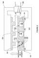
- FIG. 1is a CAD drawing illustrating one embodiment of a flow cell positioned in a magnetic housing.
- FIG. 2is a schematic diagram illustrating a cross-section of one embodiment of a flow cell positioned in a magnetic housing.
- FIG. 3is a schematic diagram illustrating an embodiment of a flow cell in which separation channel has a non-uniform width.
- FIG. 4is a schematic diagram of the top view of a flow cell.
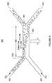
- FIG. 5is a schematic diagram illustrating a separation channel and the two inlets to the separation channel.
- FIG. 6is a schematic diagram illustrating the trajectory of target particles in the invention subject to pressure driven flow and a transverse magnetic field gradient.
- FIGS. 7A and 7Bare schematic diagrams of top-views of parallel arrays of separation channels with a fluid network for distributing a fluid stream to a plurality of separation channels and a fluid network for combining a plurality of fluid streams into a single fluid stream.
- FIGS. 8A through 8Fare schematic diagrams illustrating a manufacturing process for making the flow cell depicted in FIG. 1 .
- FIGS. 9A through 9Hare schematic diagrams illustrating alternative embodiments for the shape of the first and second magnetic surfaces of a magnetic housing.
- FIG. 10is a schematic diagram illustrating a cartridge of flow cells, wherein a plurality of flow cells are arranged in the Z-direction.
- FIGS. 11A and 11Bare prospective and cross-section schematic diagrams, respectively, of an alternative embodiment of a magnetic housing.
- FIG. 12is a flowchart showing a method for separating particles, cells, or molecules from an aqueous solution using illustrative embodiments of this invention.
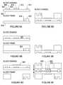
- FIG. 13is a schematic diagram comparing the top and three cross-sections of a flow cell with a barrier layer and a second flow cell without a barrier layer.
- FIG. 1is a CAD drawing illustrating one embodiment of a flow cell 102 positioned in a magnetic housing 104 .
- Flow cell 102is a removable device which is positioned in the magnetic housing 104 by means of a plate 106 .
- Plate 106can be removable from magnetic housing 104 .
- magnetic housing 104may be used with a variety of interchangeable plates. Different plates may have different surface shapes facing flow cell 102 . The different surface shapes will result in different magnetic field gradients across the flow cell 102 . A particular magnetic field gradient may be desired for a particular application. The desired magnetic field gradient may be selected by selecting a plate with a particular shape.
- plate 106is depicted with a square, ridged surface facing flow cell 102 .
- the surface of plate 106may be any of a variety of shapes suited to generate a magnetic field gradient across flow cell 102 , such as any of the shapes described in FIGS. 9A-9H , below.
- Plate 106is aligned with flow cell 102 such that the surface of plate 106 is positioned appropriately relative to the separation channels (not visible in this diagram) of flow cell 102 .
- a “tongue-and-groove” techniquecan be used, wherein tongue 108 of plate 106 is aligned with groove 110 of flow cell 102 to ensure that the parts are properly positioned relative to each other.
- magnetic housing 104can be a permanent magnet.
- the strength of the magnetic field gradient across flow cell 102may be adjusted by increasing or decreasing the proximity of plate 106 to flow cell 102 .
- Variable shim 112can be used to adjust the “air gap” between plate 106 and flow cell 102 .
- magnetic housing 104can be an electromagnet.
- magnetic housing 104is high-permeability metal and includes windings around magnetic housing 104 for carrying an electric current. When electric current is flowed through the windings, a magnetic field gradient is generated across flow cell 102 . The strength of the magnetic field gradient across flow cell 102 can be adjusted by increasing or decreasing the current flow through the windings.
- FIG. 2is a schematic diagram illustrating a cross-section of one embodiment of a flow cell 202 positioned in a magnetic housing 204 .
- Magnetic housing 204includes a magnetic source 206 .
- Magnetic source 206is depicted as an electromagnet. The remainder of magnetic housing 204 is high-permeability metal. In other embodiments, magnetic source 206 can be a permanent magnet.
- Magnetic housing 204also includes a plate 208 and a stage 210 . Plate 208 is depicted having three rectangular ridges running lengthwise above separation channels 212 , 214 , and 216 . This surface geometry enhances the field gradient across separation channels 212 , 214 , and 216 .
- Plate 208 and stage 210focus the magnetic field gradient from magnetic source 206 at the separation channels 212 , 214 , and 216 of flow cell 202 .
- sample fluid stream 222is shown at the top of separation channel 212 .
- Buffer fluid stream 224is shown at the bottom of separation channel 212 .
- Interface 238 between the sample fluid stream 222 and buffer fluid stream 224may have a sigmoidal shape due to transverse fluid-mechanical interactions at interface 238 caused by bringing the two fluid streams 222 and 224 into laminar flow at an angle, as described later with regard to FIG. 5 .
- Sample fluid stream 222contains particles, for example particles 226 and 228 . The arrows indicate that they are subject to the magnetic force in the direction of buffer fluid stream 224 .
- Buffer fluid 224contains target particle 230 .
- a target particlefor example target particle 230
- a target particlewould have entered separation channel 212 as part of sample fluid stream 222 .
- target particle 230would have been subject to a magnetic field gradient created by magnetic housing 204 , particularly by plate 208 and stage 210 , causing it to move into buffer fluid stream 224 .
- the magnetic field gradient across separation channel 212has caused target particle 230 to move into buffer fluid stream 224 .
- the magnetic field gradientwill keep target particle 230 in buffer fluid stream 224 as the pressure-driven flow of buffer fluid stream 224 carries target particle 230 to the end of separation channel 212 and through a first outlet for buffer fluid stream 224 .
- Target particle 230is thereby removed from sample fluid stream 222 which, at the end of the separation channel, flows through a second outlet for sample fluid stream 222 .
- Target particle 230can be any type of particle.
- target particle 230can be any of a molecule, cell, spore, protein, virus, bacteria, or other particle.
- Separation channels 212 , 214 , and 216can be about 200 to 300 ⁇ m wide, 50 to 200 ⁇ m tall, and 1 to 10 cm long.
- separation channels 212 , 214 , and 216may be 250 ⁇ m wide ⁇ 100 ⁇ m high, and spaced on a pitch of 500 ⁇ m. With those dimensions, a flow rate of 3 ml/min throughput can be achieved in a device area of 10 ⁇ 10 cm. Flow rate can be increased by using a flow cell with more separation channels.
- flow cell 202is depicted with only three separation channels, a flow cell of the present invention could incorporate many more separation channels, for example 200 separation channels.
- Layers 232 and 234 of flow cell 202form the top and bottom of flow channels 212 , 214 , and 216 , respectively.
- the distance between the top of separation channels 212 , 214 , and 216 , and the top of flow cell 202is determined, in party, by the thickness of layer 232 .
- the distance between the bottom of separation channels 212 , 214 , and 216 , and the bottom of the flow cell 202is determined, in party, by the thickness of layer 234 .
- the thickness of layers 232 and 234may be altered in some embodiments in order to adjust magnetic field gradient strength across separation channels 212 , 214 , and 216 .
- the channelscan be brought within 300 ⁇ m of the magnets, achieving a highly parallel array with field strengths and gradients comparable to those demonstrated in a single channel.
- the thickness of layers 232 and 234may be between 200 ⁇ m and 300 ⁇ m, such as 250 ⁇ m.
- the magnetic field gradient strengthmay also be adjusted in other ways.
- air gap 236 between flow cell 202 and plate 208 and stage 210may be altered in order to adjust magnetic field gradient strength across separation channels 212 , 214 , and 216 .
- the walls of separation channels 212 , 214 , and 216may be treated to improve bio-compatibility.
- a flow cell fabricated using Polydimethylsiloxane (PDMS)may be plasma treated to improve the bio-compatibility of the PDMS.
- the walls of separation channels 212 , 214 , 216may be coated with a bio-compatible coating in order to reduce surface interactions between the walls of the separation channels and the sample fluid stream or any target particles therein.
- the walls of separation channels 212 , 214 , and 216may be coated with Parylene.
- FIG. 3is a schematic diagram illustrating an embodiment of a flow cell in which separation channel 302 has a non-uniform width. As shown, the width of the channel in the region through which sample fluid stream 304 flows is the greater than the width of the channel in the region through which buffer fluid stream 306 flows.
- FIG. 4is a schematic diagram of the top view of a flow cell 400 .
- Flow cell 400includes four separation channels 402 , 404 , 406 , and 408 .
- Separation channel 402includes a buffer fluid stream inlet 410 , a sample fluid stream inlet 412 , a channel 414 , a buffer fluid stream outlet 416 , and a sample fluid stream outlet 418 .
- separation channels 404 , 406 , and 408also include buffer fluid stream inlets, sample fluid stream inlets, channels, buffer fluid stream outlets, and sample fluid stream outlets.
- Each of separation channels 402 , 404 , 406 , and 408may be staggered with respect to its neighbors, as depicted, in order to provide space for their respective inlets and outlets. By staggering the inlets and outlets, flow cell 400 may accommodate more separation channels in any given width.
- Flow cell 102 of FIG. 1provides an alternative illustration of area 420 of flow cell 400 in FIG. 4 .
- Flow cell 400also includes area 420 over the channels of separation channels 402 , 404 , 406 , and 408 .
- Area 420 of flow cell 400can be recessed such that the channels of separation channels 402 , 404 , 406 , and 408 may be brought into closer proximity with a plate of a magnetic housing.
- FIG. 5is a schematic diagram illustrating a detail view of a separation channel and the two inlets to the separation channel.
- a sample fluid streamis flowed from sample channel 502 into separation channel 506 .
- a buffer fluid streamis flowed from buffer channel 504 into separation channel 506 .
- the sample fluid stream and buffer fluid streamflow in laminar flow through separation channel 506 .
- Sample channel 502 and buffer channel 504are depicted merging at an acute angle.
- the two channelsmay merge at a greater or lesser angle without departing from the spirit of the present invention, though merging the two fluids at high angle may result in undesirable flow through separation channel 506 .
- merging the two fluids at a lower anglemay result in less rotation of the fluid interface as the two fluids flow through channel 506 .
- the sigmoidal interfacemay be eliminated by fabricating the flow cell with a barrier layer as described below for FIG. 13 .
- the separation channel 506 and the channels that connect to itfor example, the sample channel 502 , buffer channel 504 , and outlet channels have cross-sections that are circular, oval, or of other shape without sharp corners, to enable smooth flow of blood through the device.
- the intersections or bifurcations between these channelshave smooth rounded transitions to avoid any sharp corners, features or sudden expansions or contractions at these junctions.
- FIG. 6is a schematic diagram illustrating the trajectory of target particles in the invention subject to pressure driven flow and a transverse magnetic field gradient.
- the device 600includes a sample inlet 602 , a buffer inlet 604 , a separation channel 606 , a sample outlet 608 , and a buffer outlet 610 .
- the inlets 602 and 604are positioned to introduce two fluid streams into the separation channel 606 in laminar flow.
- the sample inlet 602introduces sample fluid stream 612 which includes target particles.
- the buffer inlet 604introduces buffer fluid stream 614 .
- the width and depth of the flow channel 606are selected to allow the fluid streams from inlets 602 and 604 to be in laminar flow through the separation channel 606 .
- the width of flow channel 606can be between 0.1 mm and 1 mm, for example 0.5 mm wide.
- the height of flow channel 606can be between 50 ⁇ m and 500 ⁇ m, for example 100 ⁇ m tall.
- the length of separation channel 606is selected to be sufficiently long to allow target particles to have sufficient time to diffuse from one wall 618 of the separation channel across the interface 620 of fluid streams 612 and 614 .
- the channelis about 2 cm long, though shorter or longer separation channels may also be suitable.
- a magnetic housingestablishes a magnetic field gradient perpendicular to the flow of the fluids through the separation channel.
- the magnetic field gradientcauses particles to move across interface 620 of the two fluid streams.
- the strength of the magnetic field gradientis selected based upon the susceptibility of the target particle. For example, in various embodiments, the field strength can be between about 100 T/m to about 480 T/m.
- sample fluid stream 612includes target particles bound to magnetic or paramagnetic nanoparticles or microparticles, (e.g., paramagnetic beads coupled to antibodies selected to bind to the target particles) to enhance the magnetic susceptibility of the target particles.
- target particlesbound to magnetic or paramagnetic nanoparticles or microparticles, (e.g., paramagnetic beads coupled to antibodies selected to bind to the target particles) to enhance the magnetic susceptibility of the target particles.
- bio-functionalized magnetic nanoparticles or microparticlesare bound to, or adsorbed by the target particles prior to being flowed through device 600 .
- sample outlet 608collects most of sample fluid stream 612 .
- Buffer outlet 610collects most of buffer fluid stream 614 , as well as target particles, such as target particle 622 , which have been moved across interface 620 of fluid streams 612 and 614 .
- FIG. 7Ais a schematic diagram of top-view of a parallel array 700 of separation channels with a fluid network for distributing a fluid stream to a plurality of separation channels and a fluid network for combining a plurality of fluid streams into a single fluid stream.
- a sample fluid stream entering sample input port 702is split into three streams going to sample inlets 704 , 706 , and 708 of separation channels 718 , 720 , and 722 , respectively.
- a buffer fluid stream entering sample input port 710is split into three streams going to buffer inlets 712 , 714 , and 716 of separation channels 718 , 720 , and 722 , respectively.
- the sample fluid streamis collected at sample outlets 724 , 726 , and 728 , respectively, and combined into sample output port 730 .
- the buffer fluid streamis collected at buffer outlets 732 , 734 , and 736 , respectively, and combined into buffer output port 738 .
- FIG. 7Bis a schematic diagram of a top-view of a parallel array 740 of devices such as device 700 , depicted in FIG. 7A , with a fluid network for distributing a fluid stream to a plurality of separation channels and a fluid network for combining a plurality of fluid streams into a single fluid stream.
- This embodimentoperates like device 700 , but where the fluid network of device 700 distributes fluid streams to three separation channels, the fluid network of this embodiment distributes fluid streams to the inlets of twenty-four separation channels. Likewise, the fluid network combines fluid streams from the outlets of 24 separation channels into a single output stream.
- array 740is depicted with twenty-four separation channels, other embodiments of the present invention can incorporate additional separation channels, for example 200 separation channels.
- FIGS. 8A through 8Fare schematic diagrams illustrating a manufacturing process for making the flow cell depicted in FIG. 1 .
- FIG. 8Adepicts a cross-section of a first substrate 802 with surface features 804 , 806 , 808 , 810 , 812 , and 814 .
- Surface features 804 , 806 , 808 , 810 , 812 , 814 , 818 , and 820are “mold masters” and may be microfabricated using standard methods, for example using SU-8 photopolymer on a silicon substrate, such as substrate 802 and 816 . Then multiple polymer devices are molded from the masters, as depicted in FIGS. 8B through 8F .
- a damis created around the edge of substrates 802 and 816 .
- a liquid polymersuch as PDMS, is disposed atop the wafer to the desired depth, as depicted in FIG. 8B .
- Surface features 804 and 814will create space which will later be used to add structural rigidity to the device.
- Surface features 806 and 818will create space which will later be used for aligning two halves of a flow cell to form a flow cell.
- Surface features 808 , 810 , and 812will create space which will later form separation channels in the finished flow cell.
- FIG. 8Bdepicts substrate 802 after polymer layer 822 has been disposed atop substrate 802 and polymer layer 824 has been disposed atop substrate 816 .
- Polymer layers 822 and 824are thick enough to cover surface features 804 , 806 , 808 , 810 , 812 , and 814 .
- the polymeris then cured. Once the polymer is cured, the damn around the edge of the substrate may be removed. Then the substrate itself may be separated from the polymer device, leaving just the polymer device, as depicted in FIG. 8C .
- FIG. 8Cdepicts polymer layer 824 after substrate 816 has been removed.
- Polymer layer 824features an empty area in the center.
- Polymer layer 824is depicted as two disconnected pieces. At this cross-section of the device, the two appear disconnected because polymer layer 824 includes a recessed rectangular area, as depicted for flow cell 102 of FIG. 1 . At other cross-sections, for example near the ends of the device, Polymer layer 824 would appear as a single solid rectangle of polymer.
- FIG. 8Calso depicts polymer layer 822 still affixed to substrate 802 .
- support 826is affixed to polymer layer 822 . Once polymer layer 824 is separated from substrate 816 , it is inverted and aligned above polymer layer 822 . Once the layers are properly aligned with respect to each other, they are brought into contact as depicted in FIG. 8D .
- FIG. 8Ddepicts polymer layer 824 inverted and affixed to polymer layer 822 .
- Polymer layers 822 and 824can be affixed in a variety of ways, such as by adhesive or by exposure to ionized oxygen to chemically bond polymer layer 822 to polymer layer 824 . Once the polymer layers 822 and 824 are bonded, polymer layer 822 is separated from substrate 802 as depicted in FIG. 8E .
- FIG. 8Edepicts polymer layers 824 and 822 after bonding.
- Polymer layer 822has been separated from substrate 802 . Once substrate 802 is removed, the remaining device forms one-half of a flow cell. Steps 8 A through 8 E are then repeated to form another half of a flow cell. The two halves are then aligned, brought into contact, and bonded, for example by adhesive or by exposure to ionized oxygen. Separation channels 828 , 830 , and 832 are visible in cross-section. The resulting flow cell is depicted in FIG. 8F .
- FIGS. 9A through 9Hare schematic diagrams illustrating alternative embodiments for the shape of the plate and the stage of a magnetic housing.
- the various geometries depicted in FIGS. 9A through 9Heach focus the magnetic field gradient across the separation channels of the flow cell in different ways.
- One of the geometriesmay be better suited to a particular application than other geometries.
- the magnetic housing of the present inventionallows a user to select a particular geometry for a particular application.
- the plateis made of extremely high permeability and high saturation (>1 Tesla) magnetic alloys, such as mu-metal.
- plate 902has rectangular ridges 906 , 908 , 910 , 912 , 914 and stage 904 has a flat featureless surface.
- plate 906has rectangular ridges 920 , 922 , 924 , 926 , 928 and stage 908 has a flat featureless surface.
- ridges 920 , 922 , 924 , 926 , and 928extend below the top surface of the flow cell, thereby reducing the distance from separation channels 929 , 930 , 931 , 932 , and 933 , respectively.
- plate 934has rectangular ridges 935 , 936 , 938 , 940 , and 942
- stage 943has rectangular ridges 944 , 946 , 948 , 950 , 952 , and 954 .
- the ridges of plate 934are in a staggered position relative to the ridges of plate 943 .
- the width of plate 956is less than the width of the array of separation channels 957 .
- Plate 956has a flat surface.
- Stage 958is wider than the array of separation channels and has a flat surface.
- the plateincluded left surface 960 and right surface 962 . Both surface 960 and surface 962 have flat faces. Stage 964 also has a flat surface.
- plate 966includes triangular ridges 970 , 972 , 973 , 974 , and 976 .
- Plate 966includes an area of flat surface separating these ridges.
- Stage 968has a flat surface.
- plate 978includes triangular ridges 982 , 984 , 986 , 988 , and 990 .
- Plate 978does not include any flat space between triangular ridges 982 , 984 , 986 , 988 , and 990 .
- Stage 980has a flat surface.
- plate 991includes convex ridges 993 , 994 , 995 , 996 , and 997 .
- Plate 991includes an area of flat surface separating these ridges.
- Stage 992has a flat surface.
- FIG. 10is a schematic diagram illustrating a cartridge 1000 of flow cells suitable for use with magnetic housings 104 or 204 of FIGS. 1 and 2 , wherein a plurality of flow cells are arranged in the Z-direction.
- the Z-directioncorresponds to the predominant direction of the magnetic field gradient created by the magnetic housings 104 or 204 .
- throughputis improved by using multiple flow cells in parallel.
- Cartridge 1000is a reusable frame for holding a plurality of flow cells.
- Cartridge 1000includes several permeable metal structures, for example structures 110 and 112 which serve as stages for flow cells above them and plates for flow cells beneath them.
- the plate side of each structure 1010 and 1012are shaped to concentrate the magnetic field gradient across respective separation channels placed beneath them.
- Cartridge 1000can be made of any permeable metal, but is made of high-permeability metal in the preferred embodiment.
- Flow cell 1002is interleaved between structure 1008 and second structure 1010 .
- Flow cell 1004is interleaved between second structure 1010 and third structure 1012 .
- Flow cell 1006is interleaved between third structure 1012 and fourth structure 1014 .
- Flow cells 1002 , 1004 , and 1006can be inserted into and removed from cartridge 1000 .
- Flow cells 1002 , 1004 , and 1006can be disposable.
- Flow cells 1002 , 1004 , and 1006each have their own input ports and output ports.
- Cartridge 1000can be positioned in a magnetic housing, for example magnetic housing 104 , discussed above in reference to FIG. 1 , or magnetic housing 1100 , as discussed below with reference to FIG. 11A .
- FIGS. 11A and 11Bare prospective and cross-section schematic diagrams, respectively, of a magnetic housing 1100 .
- Magnetic housing 1100includes a plate 1102 and a back plate 1104 .
- the embodiment depicted in FIG. 11Ais not a C-shaped magnet or electromagnet.
- a flow cellmay be placed upon plate 1102 .
- the flow cellmay be positioned on riser 1126 or, preferably, on the outer face of plate 1102 . In this configuration, the entire assembly can be placed under an optical instrument, such as a microscope objective, for observation or detection of separation performance.
- Permanent magnets 1106 , 1108 , 1110 , 1112 , 1114 , and 1116create the magnetic field gradient across the separation channels of the flow cell (not depicted). The predominant direction of the magnetic field gradient is perpendicular to the direction of fluid flow through the flow cell. Permanent magnets 1106 , 1108 , 1110 , 1112 , 1114 , and 1116 are embedded in plate 1102 . Plate 1102 and back plate 1104 do not include ridges to focus the magnetic field gradient. Although FIG. 11B is illustrated with six permanent magnets, more or fewer magnets may also be suitable.
- Magnetic housing 1100includes alignment pins 1118 , 1120 , and 1122 for aligning plate 1102 and back plate 1104 .
- Magnetic housing 1100includes adjustment screw 1124 for adjusting the distance between plate 1102 and back plate 1104 .
- the strength of the magnetic field gradient across the flow cellmay be decreased by increasing the distance between the plate 1102 and back plate 1104 , or may be increased by decreasing the distance between plate 1102 and back plate 1104 .
- FIG. 11Bis a schematic diagram of a cross-section view of the embodiment depicted in FIG. 11A .
- Plate 1102includes a riser 1126 for positioning a flow cell in close proximity to permanent magnets 1106 , 1108 , 1110 , 1112 , 1114 , and 1116 .
- FIG. 12is a flowchart showing a method for separating particles, cells, or molecules from an aqueous solution using illustrative embodiments of this invention.
- the separation processincludes inserting a flow cell into a magnetic housing (step 1202 ), determining whether the target particle has sufficient magnetic susceptibility in the first fluid stream (step 1204 ) and, if not, mixing the first fluid stream with magnetic beads in order to bind magnetic beads to the target particles to improve the magnetic susceptibility of the target particles (step 1206 ).
- the sample fluid stream and buffer fluid streamare flowed through the flow cell (step 1208 ), flowing the fluid streams through a magnetic field gradient transverse to the direction of fluid flow (step 1210 ), and flowing the sample fluid stream and buffer fluid stream out first and second outlets, respectively, at the downstream end of the separation channel (step 1212 ).
- the sample fluid streamis introduced into the flow cell at a higher, the same, or a lower flow rate than the buffer fluid stream. Steps 1208 through 1212 are repeated until the sample fluid stream has the desired concentration of target particles (step 1214 ). Once the desired concentration is reached, the two fluid streams are stopped (step 1216 ) and the flow cell can be removed from the magnetic housing (step 1218 ).
- a sample fluid containing particles, cells, or moleculesis flowed into a flow cell comprising a plurality of separation channels.
- a buffer fluid, for collecting the target particlesis flowed into the plurality of separation channels in the flow cell. These streams are flowed at flow rates that maintain laminar flow within the separation channel.
- the fluid streamsflow through the separation channel, they flow through a magnetic field gradient applied transverse to the direction of pressure-driven flow in the separation channel.
- the magnetic field gradientexerts a force on magnetically-susceptible particles, causing them to move in the direction of the buffer fluid stream.
- the magnetic field gradient strengthmust be sufficient to cause target particles to move into the buffer fluid stream.
- the sample fluid streamis collected at a sample outlet.
- the buffer fluid streamis collected at a buffer outlet.
- the sample fluid stream collected at the outlethas a lower concentration of target particles than it did at the inlet to the separation channel because target particles have migrated to the buffer fluid stream.
- a target particlemay be made more responsive to the magnetic field gradient by binding it to a magnetic nanoparticle or microparticle.
- step 1202may be preceded by mixing the sample fluid with functionalized magnetic nanoparticles or microparticles.
- the sample fluidsuch as blood, is passed repeatedly through a microfluidic mixer, as is commonly known in the art, at a relatively slow rate ( ⁇ 1 ml/min) in order to promote optimal bead-pathogen binding.
- the sample fluidAfter being allowed to bind optimally to the particles in the mixer, a process which takes approximately 5 to 10 minutes, the sample fluid is allowed to pass through the flow cell where the sample fluid is cleared of most or all magnetic beads and bound pathogens before the sample fluid exits the flow cell.
- FIG. 13is a schematic diagram comparing the top view and three cross-sections of a flow cell with a barrier layer and a second flow cell without a barrier layer.
- Flow cell 1300is depicted from the top in the X-Y plane, and in cross-section in the X-Z plane at locations A, B, and C.
- Flow cell 1300has first inlet 1304 and second inlet 1306 .
- Inlets 1304 and 1306merge to form separation channel 1318 .
- Shaded area 1310indicates where the channels overlap in the Z-direction, but the fluid stream flowing through first inlet 1304 is not in contact with the fluid stream flowing through second inlet 1306 .
- Dashed line 1312indicates the end of barrier layer 1320 . At this location, the two fluid streams first come into contact.
- the cross section of flow cell 1300 in the X-Z plane at location Ais depicted in cross section 1314 .
- first inlet 1304 and second inlet 1306do not overlap in the Z-direction.
- the cross section of flow cell 1300 in the X-Z plane at location Bis depicted in cross section 1316 .
- first inlet 1304overlaps partially with second inlet 1306 in the Z-direction, but the inlets are separated by barrier layer 1320 .
- Barrier layer 1320acts as a barrier between a fluid flowing through first inlet 1304 and a fluid flowing through 1306 .
- the cross-section of flow cell 1300 in the X-Z plane at location Cis depicted in cross-section 1318 .
- first inlet 1304overlaps second inlet 1306 such that the inlets 1304 and 1306 are aligned in the Z-direction (the predominant direction of the magnetic field gradient) and the fluid streams flowing through both are flowing predominantly in the Y-direction.
- the two fluid streamsare no longer separated by barrier layer 1320 . Because barrier layer 1320 creates a barrier between the two fluid streams until their respective directions of flow are aligned, this embodiment reduces the lateral physical shear caused by merging the two fluid streams.
- fluid interface 1306is less sigmoidal than in embodiments such as flow cell 1324 .
- Flow cell 1324is depicted from the top in the X-Y plane, and in cross-section in the X-Z plane at locations D, E, and F.
- Flow cell 1324has a first inlet 1326 and a second inlet 1328 . Without a barrier layer to separate inlets 1326 and 1328 as they merge, the fluid stream flowing through first inlet 1326 comes into contact with the fluid stream flowing through second inlet 1328 before the respective directions of their flow are aligned, as depicted in cross-section 1334 .
- first inlet 1326overlaps partially with second inlet 1328 , and the fluid streams from the respective inlets come into contact with each other.
- fluid interface 1340has a sigmoidal shape, as described above with reference to FIG. 2 , and depicted in cross-section 1336 .
- a sigmoidal fluid interfacemay have adverse effects on the separation of particles from the first fluid stream, but these adverse effects can be addressed by addition of barrier layer 1320 , as described above. In other embodiments, a sigmoidal interface may be preferred.
Landscapes
- Apparatus Associated With Microorganisms And Enzymes (AREA)
Abstract
Description
Claims (30)
Priority Applications (1)
| Application Number | Priority Date | Filing Date | Title |
|---|---|---|---|
| US12/105,805US8292083B2 (en) | 2007-04-19 | 2008-04-18 | Method and apparatus for separating particles, cells, molecules and particulates |
Applications Claiming Priority (2)
| Application Number | Priority Date | Filing Date | Title |
|---|---|---|---|
| US92535507P | 2007-04-19 | 2007-04-19 | |
| US12/105,805US8292083B2 (en) | 2007-04-19 | 2008-04-18 | Method and apparatus for separating particles, cells, molecules and particulates |
Publications (2)
| Publication Number | Publication Date |
|---|---|
| US20090078614A1 US20090078614A1 (en) | 2009-03-26 |
| US8292083B2true US8292083B2 (en) | 2012-10-23 |
Family
ID=39768684
Family Applications (1)
| Application Number | Title | Priority Date | Filing Date |
|---|---|---|---|
| US12/105,805Expired - Fee RelatedUS8292083B2 (en) | 2007-04-19 | 2008-04-18 | Method and apparatus for separating particles, cells, molecules and particulates |
Country Status (2)
| Country | Link |
|---|---|
| US (1) | US8292083B2 (en) |
| WO (1) | WO2008130618A1 (en) |
Cited By (8)
| Publication number | Priority date | Publication date | Assignee | Title |
|---|---|---|---|---|
| US20120080360A1 (en)* | 2009-04-10 | 2012-04-05 | President And Fellows Of Harvard College | Manipulation of particles in channels |
| US8956536B2 (en) | 2012-10-26 | 2015-02-17 | Becton, Dickinson And Company | Devices and methods for manipulating components in a fluid sample |
| US20150196907A1 (en)* | 2014-01-14 | 2015-07-16 | Wisconsin Alumni Research Foundation | Device And Method For Transferring A Target Between Locations |
| US20160201024A1 (en)* | 2010-04-20 | 2016-07-14 | Elteks.P.A. | Microfluidic devices and/or equipment for microfluidic devices |
| US20160258857A1 (en)* | 2009-04-27 | 2016-09-08 | Abbott Laboratories | Method for Discriminating Red Blood Cells from White Blood Cells by Using Forward Scattering from a Laser in an Automated Hematology Analyzer |
| US9885642B2 (en) | 2011-04-27 | 2018-02-06 | Becton, Dickinson And Company | Devices and methods for separating magnetically labeled moieties in a sample |
| US9989459B2 (en)* | 2013-03-15 | 2018-06-05 | Waters Technologies Corporation | Systems and methods for refractive index detection |
| US20190022664A1 (en)* | 2017-07-19 | 2019-01-24 | Auburn University | Methods for separation of magnetic nanoparticles |
Families Citing this family (40)
| Publication number | Priority date | Publication date | Assignee | Title |
|---|---|---|---|---|
| WO2007044642A2 (en) | 2005-10-06 | 2007-04-19 | President And Fellows Of Harvard College And Children's Medical Center Corporation | Device and method for combined microfluidic-micromagnetic separation of material in continuous flow |
| US20080237044A1 (en)* | 2007-03-28 | 2008-10-02 | The Charles Stark Draper Laboratory, Inc. | Method and apparatus for concentrating molecules |
| US8292083B2 (en)* | 2007-04-19 | 2012-10-23 | The Charles Stark Draper Laboratory, Inc. | Method and apparatus for separating particles, cells, molecules and particulates |
| US7837379B2 (en)* | 2007-08-13 | 2010-11-23 | The Charles Stark Draper Laboratory, Inc. | Devices for producing a continuously flowing concentration gradient in laminar flow |
| EP3404093B1 (en) | 2008-07-16 | 2019-12-11 | Children's Medical Center Corporation | Device and method for monitoring cell behaviour |
| US9156037B2 (en) | 2009-01-15 | 2015-10-13 | Children's Medical Center Corporation | Microfluidic device and uses thereof |
| KR101097357B1 (en)* | 2009-07-09 | 2011-12-23 | 한국과학기술원 | Multi function microfluidic flow control apparatus and multi function microfluidic flow control method |
| EP2454020B1 (en)* | 2009-07-17 | 2019-05-15 | Koninklijke Philips N.V. | Apparatus and method for the enrichment of magnetic particles |
| US8083069B2 (en)* | 2009-07-31 | 2011-12-27 | General Electric Company | High throughput magnetic isolation technique and device for biological materials |
| IN2012DN06589A (en) | 2010-01-19 | 2015-10-23 | Harvard College | |
| US8590710B2 (en)* | 2010-06-10 | 2013-11-26 | Samsung Electronics Co., Ltd. | Target particles-separating device and method using multi-orifice flow fractionation channel |
| KR20120032255A (en) | 2010-09-28 | 2012-04-05 | 삼성전자주식회사 | Cell separation device and cell separation method using magnetic force |
| US9815060B2 (en) | 2010-11-18 | 2017-11-14 | The Regents Of The University Of California | Method and device for high-throughput solution exchange for cell and particle suspensions |
| WO2012067985A2 (en)* | 2010-11-18 | 2012-05-24 | The Regents Of The University Of California | Method and device for high-throughput solution exchange for cell and particle suspensions |
| CA2828110C (en) | 2011-02-28 | 2020-03-31 | President And Fellows Of Harvard College | Cell culture system |
| AU2012236128A1 (en)* | 2011-04-01 | 2013-10-31 | Children's Medical Center Corporation | Dialysis like therapeutic (DLT) device |
| WO2013012924A2 (en) | 2011-07-18 | 2013-01-24 | President And Fellows Of Harvard College | Engineered microbe-targeting molecules and uses thereof |
| WO2013086486A1 (en) | 2011-12-09 | 2013-06-13 | President And Fellows Of Harvard College | Integrated human organ-on-chip microphysiological systems |
| EP2820147B1 (en) | 2012-02-29 | 2018-08-08 | President and Fellows of Harvard College | Rapid antibiotic susceptibility testing |
| US20160299132A1 (en) | 2013-03-15 | 2016-10-13 | Ancera, Inc. | Systems and methods for bead-based assays in ferrofluids |
| US10551379B2 (en) | 2013-03-15 | 2020-02-04 | President And Fellows Of Harvard College | Methods and compositions for improving detection and/or capture of a target entity |
| WO2014144782A2 (en) | 2013-03-15 | 2014-09-18 | Ancera, Inc. | Systems and methods for active particle separation |
| US20160296944A1 (en)* | 2013-03-15 | 2016-10-13 | Ancera, Inc. | Systems and methods for three-dimensional extraction of target particles ferrofluids |
| EP3848044A1 (en) | 2013-05-21 | 2021-07-14 | President and Fellows of Harvard College | Engineered heme-binding compositions and uses thereof |
| EP3024582A4 (en) | 2013-07-22 | 2017-03-08 | President and Fellows of Harvard College | Microfluidic cartridge assembly |
| US10513546B2 (en) | 2013-12-18 | 2019-12-24 | President And Fellows Of Harvard College | CRP capture/detection of gram positive bacteria |
| CA2944220C (en) | 2013-12-20 | 2024-01-02 | President And Fellows Of Harvard College | Organomimetic devices and methods of use and manufacturing thereof |
| GB2538012A (en) | 2013-12-20 | 2016-11-02 | Harvard College | Low shear microfluidic devices and methods of use and manufacturing thereof |
| US20150179321A1 (en)* | 2013-12-20 | 2015-06-25 | Massachusetts Institute Of Technology | Controlled liquid/solid mobility using external fields on lubricant-impregnated surfaces |
| GB2546424A (en) | 2014-07-14 | 2017-07-19 | Harvard College | Systems and methods for improved performance of fluidic and microfluidic systems |
| US11285490B2 (en) | 2015-06-26 | 2022-03-29 | Ancera, Llc | Background defocusing and clearing in ferrofluid-based capture assays |
| US10202569B2 (en) | 2015-07-24 | 2019-02-12 | President And Fellows Of Harvard College | Radial microfluidic devices and methods of use |
| WO2017024114A1 (en) | 2015-08-06 | 2017-02-09 | President And Fellows Of Harvard College | Improved microbe-binding molecules and uses thereof |
| KR101855490B1 (en)* | 2016-01-22 | 2018-05-08 | 한국과학기술원 | Method For Separating And Washing Of Microparticles Via A Stratified Coflow Of Non-Newtonian And Newtonian Fluids |
| US12104174B2 (en) | 2016-09-13 | 2024-10-01 | President And Fellows Of Harvard College | Methods relating to intestinal organ-on-a-chip |
| KR101888636B1 (en) | 2017-06-02 | 2018-08-14 | 지트로닉스 주식회사 | Magnetophoresis biochip |
| WO2019031815A1 (en)* | 2017-08-07 | 2019-02-14 | 울산과학기술원 | System and method for fluid separation using magnetic particles |
| EP3787794A1 (en)* | 2018-04-30 | 2021-03-10 | United Therapeutics Corporation | Apparatus and method for controlling fluid flow |
| US12263482B1 (en)* | 2020-06-03 | 2025-04-01 | 10X Genomics, Inc. | Methods and devices for magnetic separation in a flow path |
| CN113063779A (en)* | 2021-03-15 | 2021-07-02 | 埃妥生物科技(杭州)有限公司 | A sampler and a mixing device for samples and reagents |
Citations (103)
| Publication number | Priority date | Publication date | Assignee | Title |
|---|---|---|---|---|
| US1583051A (en) | 1922-02-08 | 1926-05-04 | Kennedy Edward | Drainage apparatus for refrigerators |
| US2608390A (en) | 1941-07-11 | 1952-08-26 | Comb Eng Superheater Inc | Superheater element with trifurcate groups |
| US3127738A (en) | 1961-05-26 | 1964-04-07 | United Aircraft Corp | Gas bleed from rocket chamber |
| US3128794A (en) | 1963-01-08 | 1964-04-14 | Du Pont | Fluid flow inverter |
| US3342378A (en) | 1964-09-15 | 1967-09-19 | Dow Chemical Co | Nozzle attachment for use in die casting |
| US3421739A (en) | 1967-06-27 | 1969-01-14 | Rexall Drug Chemical | Apparatus for gravity blending of solids |
| US3470912A (en) | 1966-11-30 | 1969-10-07 | Du Pont | Flow inverter |
| US3506244A (en) | 1967-06-29 | 1970-04-14 | Courtaulds Ltd | Mixing apparatus |
| US3507301A (en) | 1966-04-21 | 1970-04-21 | Robert H Larson | Collector and method of making the same |
| US3510240A (en) | 1968-10-25 | 1970-05-05 | Magic Chef Inc | Pilot burner |
| US3847773A (en) | 1973-06-11 | 1974-11-12 | Technicon Instr | Method and apparatus for curtain electrophoresis |
| US3852013A (en) | 1972-09-19 | 1974-12-03 | H Upmeier | Extruder for plastics material, particularly thermoplastic or non-cross-linked elastomeric materials |
| US3963221A (en) | 1974-02-28 | 1976-06-15 | Union Carbide Corporation | Mixing apparatus |
| US4214610A (en) | 1977-11-25 | 1980-07-29 | The Boeing Company | Flow control system for concentric annular fluid streams |
| US4222671A (en) | 1978-09-05 | 1980-09-16 | Gilmore Oscar Patrick | Static mixer |
| US4285602A (en) | 1979-05-14 | 1981-08-25 | Union Carbide Corporation | Method and apparatus for the blending of granular materials |
| US4426344A (en) | 1980-07-05 | 1984-01-17 | Hoechst Aktiengesellschaft | Coextrusion process and apparatus for manufacturing multi-layered flat films of thermoplastic materials |
| US4465582A (en) | 1982-05-24 | 1984-08-14 | Mcdonnell Douglas Corporation | Continuous flow electrophoresis apparatus |
| US4473300A (en) | 1983-08-29 | 1984-09-25 | Phillips Petroleum Company | Method and apparatus for blending solids or the like |
| US4518260A (en) | 1983-08-26 | 1985-05-21 | Phillips Petroleum Company | Apparatus for blending solids or the like |
| US4553849A (en) | 1983-08-26 | 1985-11-19 | Phillips Petroleum Company | Method for blending solids or the like |
| DE3624626A1 (en) | 1986-07-18 | 1988-01-28 | Pilgrimm Herbert | Process for separating off substances from a mixture of substances using magnetic liquids |
| US4948481A (en) | 1988-08-27 | 1990-08-14 | Hoechst Aktiengesellschaft | Process and device for the electrophoretic separation, purification and concentration of charged or polarizable macromolecules |
| US4983038A (en) | 1987-04-08 | 1991-01-08 | Hitachi, Ltd. | Sheath flow type flow-cell device |
| DE3926466A1 (en) | 1989-08-10 | 1991-02-14 | Messerschmitt Boelkow Blohm | Micro-reactor for temp.-controlled chemical reactions - comprises stack of grooved plates |
| EP0434556A1 (en) | 1989-12-20 | 1991-06-26 | F C B | High intensity wet magnetic separator |
| US5094788A (en) | 1990-12-21 | 1992-03-10 | The Dow Chemical Company | Interfacial surface generator |
| US5180480A (en) | 1991-01-28 | 1993-01-19 | Ciba-Geigy Corporation | Apparatus for the preparation of samples, especially for analytical purposes |
| US5185071A (en) | 1990-10-30 | 1993-02-09 | Board Of Regents, The University Of Texas System | Programmable electrophoresis with integrated and multiplexed control |
| US5250188A (en) | 1989-09-01 | 1993-10-05 | Brigham Young University | Process of removing and concentrating desired molecules from solutions |
| US5269995A (en) | 1992-10-02 | 1993-12-14 | The Dow Chemical Company | Coextrusion of multilayer articles using protective boundary layers and apparatus therefor |
| US5275706A (en) | 1991-11-29 | 1994-01-04 | Gerhard Weber | Method and apparatus for continuous, carrier-free deflection electrophoresis |
| US5518311A (en) | 1993-04-08 | 1996-05-21 | Abb Management Ag | Mixing chamber with vortex generators for flowing gases |
| US5531831A (en) | 1994-12-12 | 1996-07-02 | Minnesota Mining And Manufacturing Company | Static blending device |
| WO1996026782A1 (en) | 1995-02-27 | 1996-09-06 | Miltenyi Biotech, Inc. | Improved magnetic separation apparatus and method |
| US5620714A (en) | 1992-08-14 | 1997-04-15 | Machinefabriek "De Rollepaal" B.V. | Distributor head for forming a tubular profile from one or more streams of extruded thermoplastic material |
| US5765373A (en) | 1992-11-02 | 1998-06-16 | Bittle; James J. | Gas flow headers for internal combustion engines |
| US5780067A (en) | 1996-09-10 | 1998-07-14 | Extrusion Dies, Inc. | Adjustable coextrusion feedblock |
| US5803600A (en) | 1994-05-09 | 1998-09-08 | Forschungszentrum Karlsruhe Gmbh | Static micromixer with heat exchanger |
| US5816045A (en) | 1995-03-23 | 1998-10-06 | Mercedes-Benz Ag | Fan-type exhaust gas manifold for multi-cylinder internal-combustion engines and method of making same |
| US5824204A (en) | 1996-06-27 | 1998-10-20 | Ic Sensors, Inc. | Micromachined capillary electrophoresis device |
| US5826981A (en) | 1996-08-26 | 1998-10-27 | Nova Biomedical Corporation | Apparatus for mixing laminar and turbulent flow streams |
| DE19748481A1 (en) | 1997-11-03 | 1999-05-12 | Inst Mikrotechnik Mainz Gmbh | Micro-mixer for production of ethyl-oxide |
| US5904424A (en) | 1995-03-30 | 1999-05-18 | Merck Patent Gesellschaft Mit Beschrankter Haftung | Device for mixing small quantities of liquids |
| US5932100A (en) | 1995-06-16 | 1999-08-03 | University Of Washington | Microfabricated differential extraction device and method |
| US6082891A (en) | 1995-10-28 | 2000-07-04 | Forschungszentrum Karlsruhe Gmbh | Static micromixer |
| US6136272A (en) | 1997-09-26 | 2000-10-24 | University Of Washington | Device for rapidly joining and splitting fluid layers |
| US6136171A (en) | 1998-09-18 | 2000-10-24 | The University Of Utah Research Foundation | Micromachined electrical field-flow fractionation system |
| US6143152A (en) | 1997-11-07 | 2000-11-07 | The Regents Of The University Of California | Microfabricated capillary array electrophoresis device and method |
| US6190034B1 (en) | 1995-10-03 | 2001-02-20 | Danfoss A/S | Micro-mixer and mixing method |
| US6221677B1 (en) | 1997-09-26 | 2001-04-24 | University Of Washington | Simultaneous particle separation and chemical reaction |
| US6225497B1 (en) | 1998-01-09 | 2001-05-01 | Bayer Aktiengesellschaft | Process for the phosgenation of amines in the gas phase using microstructure mixers |
| US6264900B1 (en) | 1995-11-06 | 2001-07-24 | Bayer Aktiengesellschaft | Device for carrying out chemical reactions using a microlaminar mixer |
| WO2001087458A1 (en) | 2000-05-12 | 2001-11-22 | University Of Cincinnati | Magnetic bead-based arrays |
| US6321998B1 (en) | 1995-11-06 | 2001-11-27 | Bayer Aktiengesellschaft | Method of producing dispersions and carrying out of chemical reactions in the disperse phase |
| US6328868B1 (en) | 1997-03-21 | 2001-12-11 | Gerhard Weber | Method for carrier-free deflection electrophoresis |
| US20020045738A1 (en) | 1999-04-30 | 2002-04-18 | Sharat Singh | Oligonucleotide-binding e-tag probe compositions |
| US6387707B1 (en) | 1996-04-25 | 2002-05-14 | Bioarray Solutions | Array Cytometry |
| US20020057627A1 (en) | 1999-06-19 | 2002-05-16 | Klaus Schubert | Static micromixer |
| US6432630B1 (en)* | 1996-09-04 | 2002-08-13 | Scandinanian Micro Biodevices A/S | Micro-flow system for particle separation and analysis |
| US6454945B1 (en) | 1995-06-16 | 2002-09-24 | University Of Washington | Microfabricated devices and methods |
| US6467503B2 (en) | 1997-06-06 | 2002-10-22 | Armstrong International, Inc. | Manifold and station for mounting steam/condensate responsive devices in a condensate return line |
| US6479734B2 (en) | 1998-06-10 | 2002-11-12 | Kyushu University | DNA fragment responsive to low temperatures and a plant transformed with the DNA fragment |
| US20020187503A1 (en)* | 2001-05-02 | 2002-12-12 | Michael Harrold | Concentration and purification of analytes using electric fields |
| US20030057092A1 (en) | 2000-10-31 | 2003-03-27 | Caliper Technologies Corp. | Microfluidic methods, devices and systems for in situ material concentration |
| US6623860B2 (en) | 2000-10-10 | 2003-09-23 | Aclara Biosciences, Inc. | Multilevel flow structures |
| US6676835B2 (en) | 2000-08-07 | 2004-01-13 | Nanostream, Inc. | Microfluidic separators |
| US6692627B1 (en) | 2000-09-26 | 2004-02-17 | Boise State University | Electrical field flow fractionation (EFFF) using an electrically insulated flow channel |
| US6695147B1 (en) | 1996-06-14 | 2004-02-24 | University Of Washington | Absorption-enhanced differential extraction device |
| US6705357B2 (en) | 2000-09-18 | 2004-03-16 | President And Fellows Of Harvard College | Method and apparatus for gradient generation |
| US20040092033A1 (en)* | 2002-10-18 | 2004-05-13 | Nanostream, Inc. | Systems and methods for preparing microfluidic devices for operation |
| US20040182707A1 (en) | 2002-10-16 | 2004-09-23 | Cellectricon Ab | Nanoelectrodes and nanotips for recording transmembrane currents in a plurality of cells |
| US20040256230A1 (en) | 1999-06-03 | 2004-12-23 | University Of Washington | Microfluidic devices for transverse electrophoresis and isoelectric focusing |
| US20040257907A1 (en) | 2003-06-19 | 2004-12-23 | Agency For Science, Technology And Research | Method and apparatus for mixing fluids |
| US6845787B2 (en) | 2002-02-23 | 2005-01-25 | Nanostream, Inc. | Microfluidic multi-splitter |
| US6851846B2 (en) | 2001-06-15 | 2005-02-08 | Minolta Co., Ltd. | Mixing method, mixing structure, micromixer and microchip having the mixing structure |
| US20050061669A1 (en) | 2001-08-24 | 2005-03-24 | Applera Corporation | Bubble-free and pressure-generating electrodes for electrophoretic and electroosmotic devices |
| US6877892B2 (en) | 2002-01-11 | 2005-04-12 | Nanostream, Inc. | Multi-stream microfluidic aperture mixers |
| US6890093B2 (en) | 2000-08-07 | 2005-05-10 | Nanostream, Inc. | Multi-stream microfludic mixers |
| US6905324B2 (en) | 2002-04-26 | 2005-06-14 | Cloeren Incorporated | Interface control |
| US6923907B2 (en) | 2002-02-13 | 2005-08-02 | Nanostream, Inc. | Separation column devices and fabrication methods |
| US20050178701A1 (en) | 2004-01-26 | 2005-08-18 | General Electric Company | Method for magnetic/ferrofluid separation of particle fractions |
| US6958245B2 (en) | 1996-04-25 | 2005-10-25 | Bioarray Solutions Ltd. | Array cytometry |
| US6981522B2 (en) | 2001-06-07 | 2006-01-03 | Nanostream, Inc. | Microfluidic devices with distributing inputs |
| US7005050B2 (en) | 2001-10-24 | 2006-02-28 | The Regents Of The University Of Michigan | Electrophoresis in microfabricated devices using photopolymerized polyacrylamide gels and electrode-defined sample injection |
| US7033473B2 (en) | 2000-06-14 | 2006-04-25 | Board Of Regents, University Of Texas | Method and apparatus for combined magnetophoretic and dielectrophoretic manipulation of analyte mixtures |
| US7077906B2 (en) | 1998-12-29 | 2006-07-18 | Pirelli Cavi E Sistemi S.P.A. | Apparatus for continuously introducing a substance in liquid phase into plastics granules |
| US7100636B2 (en) | 2003-02-19 | 2006-09-05 | King Nelson J | Multiple outlet single valve |
| US7135144B2 (en) | 1997-08-13 | 2006-11-14 | Cepheid | Method for the manipulation of a fluid sample |
| EP1742057A1 (en) | 2005-07-08 | 2007-01-10 | Stichting Voor De Technische Wetenschappen | Device and method for the separation of particles |
| US7258774B2 (en)* | 2000-10-03 | 2007-08-21 | California Institute Of Technology | Microfluidic devices and methods of use |
| US7261812B1 (en) | 2002-02-13 | 2007-08-28 | Nanostream, Inc. | Multi-column separation devices and methods |
| US7316503B2 (en) | 2003-05-08 | 2008-01-08 | Sulzer Chemtech Ag | Static mixer |
| US20080067068A1 (en)* | 2006-09-19 | 2008-03-20 | Vanderbilt University | DC-dielectrophoresis microfluidic apparatus, and applications of same |
| US20080237044A1 (en)* | 2007-03-28 | 2008-10-02 | The Charles Stark Draper Laboratory, Inc. | Method and apparatus for concentrating molecules |
| US7472794B2 (en)* | 2002-02-04 | 2009-01-06 | Colorado School Of Mines | Cell sorting device and method of manufacturing the same |
| US7487799B2 (en) | 2003-07-22 | 2009-02-10 | Aloys Wobben | Flow channel for liquids |
| US20090044619A1 (en) | 2007-08-13 | 2009-02-19 | Fiering Jason O | Devices and methods for producing a continuously flowing concentration gradient in laminar flow |
| US20090078614A1 (en)* | 2007-04-19 | 2009-03-26 | Mathew Varghese | Method and apparatus for separating particles, cells, molecules and particulates |
| US20090086572A1 (en) | 2007-09-28 | 2009-04-02 | Fujifilm Corporation | Microdevice and fluid mixing method |
| US7520661B1 (en) | 2006-11-20 | 2009-04-21 | Aeromed Technologies Llc | Static mixer |
| US7632405B2 (en)* | 1995-02-21 | 2009-12-15 | Iqbal Waheed Siddiqi | Apparatus for processing magnetic particles |
| US7699767B2 (en)* | 2002-07-31 | 2010-04-20 | Arryx, Inc. | Multiple laminar flow-based particle and cellular separation with laser steering |
- 2008
- 2008-04-18USUS12/105,805patent/US8292083B2/ennot_activeExpired - Fee Related
- 2008-04-18WOPCT/US2008/005002patent/WO2008130618A1/enactiveApplication Filing
Patent Citations (109)
| Publication number | Priority date | Publication date | Assignee | Title |
|---|---|---|---|---|
| US1583051A (en) | 1922-02-08 | 1926-05-04 | Kennedy Edward | Drainage apparatus for refrigerators |
| US2608390A (en) | 1941-07-11 | 1952-08-26 | Comb Eng Superheater Inc | Superheater element with trifurcate groups |
| US3127738A (en) | 1961-05-26 | 1964-04-07 | United Aircraft Corp | Gas bleed from rocket chamber |
| US3128794A (en) | 1963-01-08 | 1964-04-14 | Du Pont | Fluid flow inverter |
| US3342378A (en) | 1964-09-15 | 1967-09-19 | Dow Chemical Co | Nozzle attachment for use in die casting |
| US3507301A (en) | 1966-04-21 | 1970-04-21 | Robert H Larson | Collector and method of making the same |
| US3470912A (en) | 1966-11-30 | 1969-10-07 | Du Pont | Flow inverter |
| US3421739A (en) | 1967-06-27 | 1969-01-14 | Rexall Drug Chemical | Apparatus for gravity blending of solids |
| US3506244A (en) | 1967-06-29 | 1970-04-14 | Courtaulds Ltd | Mixing apparatus |
| US3510240A (en) | 1968-10-25 | 1970-05-05 | Magic Chef Inc | Pilot burner |
| US3852013A (en) | 1972-09-19 | 1974-12-03 | H Upmeier | Extruder for plastics material, particularly thermoplastic or non-cross-linked elastomeric materials |
| US3847773A (en) | 1973-06-11 | 1974-11-12 | Technicon Instr | Method and apparatus for curtain electrophoresis |
| US3963221A (en) | 1974-02-28 | 1976-06-15 | Union Carbide Corporation | Mixing apparatus |
| US4214610A (en) | 1977-11-25 | 1980-07-29 | The Boeing Company | Flow control system for concentric annular fluid streams |
| US4222671A (en) | 1978-09-05 | 1980-09-16 | Gilmore Oscar Patrick | Static mixer |
| US4285602A (en) | 1979-05-14 | 1981-08-25 | Union Carbide Corporation | Method and apparatus for the blending of granular materials |
| US4426344A (en) | 1980-07-05 | 1984-01-17 | Hoechst Aktiengesellschaft | Coextrusion process and apparatus for manufacturing multi-layered flat films of thermoplastic materials |
| US4465582A (en) | 1982-05-24 | 1984-08-14 | Mcdonnell Douglas Corporation | Continuous flow electrophoresis apparatus |
| US4518260A (en) | 1983-08-26 | 1985-05-21 | Phillips Petroleum Company | Apparatus for blending solids or the like |
| US4553849A (en) | 1983-08-26 | 1985-11-19 | Phillips Petroleum Company | Method for blending solids or the like |
| US4473300A (en) | 1983-08-29 | 1984-09-25 | Phillips Petroleum Company | Method and apparatus for blending solids or the like |
| DE3624626A1 (en) | 1986-07-18 | 1988-01-28 | Pilgrimm Herbert | Process for separating off substances from a mixture of substances using magnetic liquids |
| US4983038A (en) | 1987-04-08 | 1991-01-08 | Hitachi, Ltd. | Sheath flow type flow-cell device |
| US4948481A (en) | 1988-08-27 | 1990-08-14 | Hoechst Aktiengesellschaft | Process and device for the electrophoretic separation, purification and concentration of charged or polarizable macromolecules |
| DE3926466A1 (en) | 1989-08-10 | 1991-02-14 | Messerschmitt Boelkow Blohm | Micro-reactor for temp.-controlled chemical reactions - comprises stack of grooved plates |
| US5250188A (en) | 1989-09-01 | 1993-10-05 | Brigham Young University | Process of removing and concentrating desired molecules from solutions |
| EP0434556A1 (en) | 1989-12-20 | 1991-06-26 | F C B | High intensity wet magnetic separator |
| US5185071A (en) | 1990-10-30 | 1993-02-09 | Board Of Regents, The University Of Texas System | Programmable electrophoresis with integrated and multiplexed control |
| US5094788A (en) | 1990-12-21 | 1992-03-10 | The Dow Chemical Company | Interfacial surface generator |
| US5180480A (en) | 1991-01-28 | 1993-01-19 | Ciba-Geigy Corporation | Apparatus for the preparation of samples, especially for analytical purposes |
| US5275706A (en) | 1991-11-29 | 1994-01-04 | Gerhard Weber | Method and apparatus for continuous, carrier-free deflection electrophoresis |
| US5620714A (en) | 1992-08-14 | 1997-04-15 | Machinefabriek "De Rollepaal" B.V. | Distributor head for forming a tubular profile from one or more streams of extruded thermoplastic material |
| US5269995A (en) | 1992-10-02 | 1993-12-14 | The Dow Chemical Company | Coextrusion of multilayer articles using protective boundary layers and apparatus therefor |
| US5765373A (en) | 1992-11-02 | 1998-06-16 | Bittle; James J. | Gas flow headers for internal combustion engines |
| US5518311A (en) | 1993-04-08 | 1996-05-21 | Abb Management Ag | Mixing chamber with vortex generators for flowing gases |
| US5803600A (en) | 1994-05-09 | 1998-09-08 | Forschungszentrum Karlsruhe Gmbh | Static micromixer with heat exchanger |
| US5531831A (en) | 1994-12-12 | 1996-07-02 | Minnesota Mining And Manufacturing Company | Static blending device |
| US7632405B2 (en)* | 1995-02-21 | 2009-12-15 | Iqbal Waheed Siddiqi | Apparatus for processing magnetic particles |
| WO1996026782A1 (en) | 1995-02-27 | 1996-09-06 | Miltenyi Biotech, Inc. | Improved magnetic separation apparatus and method |
| US5816045A (en) | 1995-03-23 | 1998-10-06 | Mercedes-Benz Ag | Fan-type exhaust gas manifold for multi-cylinder internal-combustion engines and method of making same |
| US5904424A (en) | 1995-03-30 | 1999-05-18 | Merck Patent Gesellschaft Mit Beschrankter Haftung | Device for mixing small quantities of liquids |
| US6454945B1 (en) | 1995-06-16 | 2002-09-24 | University Of Washington | Microfabricated devices and methods |
| US5932100A (en) | 1995-06-16 | 1999-08-03 | University Of Washington | Microfabricated differential extraction device and method |
| US6190034B1 (en) | 1995-10-03 | 2001-02-20 | Danfoss A/S | Micro-mixer and mixing method |
| US6082891A (en) | 1995-10-28 | 2000-07-04 | Forschungszentrum Karlsruhe Gmbh | Static micromixer |
| US6321998B1 (en) | 1995-11-06 | 2001-11-27 | Bayer Aktiengesellschaft | Method of producing dispersions and carrying out of chemical reactions in the disperse phase |
| US6264900B1 (en) | 1995-11-06 | 2001-07-24 | Bayer Aktiengesellschaft | Device for carrying out chemical reactions using a microlaminar mixer |
| US6299657B1 (en) | 1995-11-06 | 2001-10-09 | Bayer Aktiengesellschaft | Process for carrying out chemical reactions using a microlaminar mixer |
| US6958245B2 (en) | 1996-04-25 | 2005-10-25 | Bioarray Solutions Ltd. | Array cytometry |
| US7056746B2 (en) | 1996-04-25 | 2006-06-06 | Bioarray Solutions Ltd. | Array cytometry |
| US6387707B1 (en) | 1996-04-25 | 2002-05-14 | Bioarray Solutions | Array Cytometry |
| US6695147B1 (en) | 1996-06-14 | 2004-02-24 | University Of Washington | Absorption-enhanced differential extraction device |
| US5824204A (en) | 1996-06-27 | 1998-10-20 | Ic Sensors, Inc. | Micromachined capillary electrophoresis device |
| US5826981A (en) | 1996-08-26 | 1998-10-27 | Nova Biomedical Corporation | Apparatus for mixing laminar and turbulent flow streams |
| US7138269B2 (en)* | 1996-09-04 | 2006-11-21 | Inverness Medical Switzerland Gmbh | Microflow system for particle separation and analysis |
| US6432630B1 (en)* | 1996-09-04 | 2002-08-13 | Scandinanian Micro Biodevices A/S | Micro-flow system for particle separation and analysis |
| US5780067A (en) | 1996-09-10 | 1998-07-14 | Extrusion Dies, Inc. | Adjustable coextrusion feedblock |
| US6328868B1 (en) | 1997-03-21 | 2001-12-11 | Gerhard Weber | Method for carrier-free deflection electrophoresis |
| US6467503B2 (en) | 1997-06-06 | 2002-10-22 | Armstrong International, Inc. | Manifold and station for mounting steam/condensate responsive devices in a condensate return line |
| US7135144B2 (en) | 1997-08-13 | 2006-11-14 | Cepheid | Method for the manipulation of a fluid sample |
| US6221677B1 (en) | 1997-09-26 | 2001-04-24 | University Of Washington | Simultaneous particle separation and chemical reaction |
| US6136272A (en) | 1997-09-26 | 2000-10-24 | University Of Washington | Device for rapidly joining and splitting fluid layers |
| DE19748481A1 (en) | 1997-11-03 | 1999-05-12 | Inst Mikrotechnik Mainz Gmbh | Micro-mixer for production of ethyl-oxide |
| US6143152A (en) | 1997-11-07 | 2000-11-07 | The Regents Of The University Of California | Microfabricated capillary array electrophoresis device and method |
| US6225497B1 (en) | 1998-01-09 | 2001-05-01 | Bayer Aktiengesellschaft | Process for the phosgenation of amines in the gas phase using microstructure mixers |
| US6479734B2 (en) | 1998-06-10 | 2002-11-12 | Kyushu University | DNA fragment responsive to low temperatures and a plant transformed with the DNA fragment |
| US6136171A (en) | 1998-09-18 | 2000-10-24 | The University Of Utah Research Foundation | Micromachined electrical field-flow fractionation system |
| US7077906B2 (en) | 1998-12-29 | 2006-07-18 | Pirelli Cavi E Sistemi S.P.A. | Apparatus for continuously introducing a substance in liquid phase into plastics granules |
| US20020045738A1 (en) | 1999-04-30 | 2002-04-18 | Sharat Singh | Oligonucleotide-binding e-tag probe compositions |
| US20040256230A1 (en) | 1999-06-03 | 2004-12-23 | University Of Washington | Microfluidic devices for transverse electrophoresis and isoelectric focusing |
| US20020057627A1 (en) | 1999-06-19 | 2002-05-16 | Klaus Schubert | Static micromixer |
| US6802640B2 (en) | 1999-06-19 | 2004-10-12 | Forschungszentrum Karlsruhc Gmbh | Static micromixer |
| WO2001087458A1 (en) | 2000-05-12 | 2001-11-22 | University Of Cincinnati | Magnetic bead-based arrays |
| US7033473B2 (en) | 2000-06-14 | 2006-04-25 | Board Of Regents, University Of Texas | Method and apparatus for combined magnetophoretic and dielectrophoretic manipulation of analyte mixtures |
| US6890093B2 (en) | 2000-08-07 | 2005-05-10 | Nanostream, Inc. | Multi-stream microfludic mixers |
| US6676835B2 (en) | 2000-08-07 | 2004-01-13 | Nanostream, Inc. | Microfluidic separators |
| US6935772B2 (en) | 2000-08-07 | 2005-08-30 | Nanostream, Inc. | Fluidic mixer in microfluidic system |
| US6705357B2 (en) | 2000-09-18 | 2004-03-16 | President And Fellows Of Harvard College | Method and apparatus for gradient generation |
| US6692627B1 (en) | 2000-09-26 | 2004-02-17 | Boise State University | Electrical field flow fractionation (EFFF) using an electrically insulated flow channel |
| US7258774B2 (en)* | 2000-10-03 | 2007-08-21 | California Institute Of Technology | Microfluidic devices and methods of use |
| US6623860B2 (en) | 2000-10-10 | 2003-09-23 | Aclara Biosciences, Inc. | Multilevel flow structures |
| US20030057092A1 (en) | 2000-10-31 | 2003-03-27 | Caliper Technologies Corp. | Microfluidic methods, devices and systems for in situ material concentration |
| US20020187503A1 (en)* | 2001-05-02 | 2002-12-12 | Michael Harrold | Concentration and purification of analytes using electric fields |
| US6981522B2 (en) | 2001-06-07 | 2006-01-03 | Nanostream, Inc. | Microfluidic devices with distributing inputs |
| US6851846B2 (en) | 2001-06-15 | 2005-02-08 | Minolta Co., Ltd. | Mixing method, mixing structure, micromixer and microchip having the mixing structure |
| US20050061669A1 (en) | 2001-08-24 | 2005-03-24 | Applera Corporation | Bubble-free and pressure-generating electrodes for electrophoretic and electroosmotic devices |
| US7005050B2 (en) | 2001-10-24 | 2006-02-28 | The Regents Of The University Of Michigan | Electrophoresis in microfabricated devices using photopolymerized polyacrylamide gels and electrode-defined sample injection |
| US6877892B2 (en) | 2002-01-11 | 2005-04-12 | Nanostream, Inc. | Multi-stream microfluidic aperture mixers |
| US7472794B2 (en)* | 2002-02-04 | 2009-01-06 | Colorado School Of Mines | Cell sorting device and method of manufacturing the same |
| US7261812B1 (en) | 2002-02-13 | 2007-08-28 | Nanostream, Inc. | Multi-column separation devices and methods |
| US6923907B2 (en) | 2002-02-13 | 2005-08-02 | Nanostream, Inc. | Separation column devices and fabrication methods |
| US6845787B2 (en) | 2002-02-23 | 2005-01-25 | Nanostream, Inc. | Microfluidic multi-splitter |
| US6905324B2 (en) | 2002-04-26 | 2005-06-14 | Cloeren Incorporated | Interface control |
| US7699767B2 (en)* | 2002-07-31 | 2010-04-20 | Arryx, Inc. | Multiple laminar flow-based particle and cellular separation with laser steering |
| US20040182707A1 (en) | 2002-10-16 | 2004-09-23 | Cellectricon Ab | Nanoelectrodes and nanotips for recording transmembrane currents in a plurality of cells |
| US20040092033A1 (en)* | 2002-10-18 | 2004-05-13 | Nanostream, Inc. | Systems and methods for preparing microfluidic devices for operation |
| US7100636B2 (en) | 2003-02-19 | 2006-09-05 | King Nelson J | Multiple outlet single valve |
| US7316503B2 (en) | 2003-05-08 | 2008-01-08 | Sulzer Chemtech Ag | Static mixer |
| US20040257907A1 (en) | 2003-06-19 | 2004-12-23 | Agency For Science, Technology And Research | Method and apparatus for mixing fluids |
| US7487799B2 (en) | 2003-07-22 | 2009-02-10 | Aloys Wobben | Flow channel for liquids |
| US20050178701A1 (en) | 2004-01-26 | 2005-08-18 | General Electric Company | Method for magnetic/ferrofluid separation of particle fractions |
| EP1742057A1 (en) | 2005-07-08 | 2007-01-10 | Stichting Voor De Technische Wetenschappen | Device and method for the separation of particles |
| US20080067068A1 (en)* | 2006-09-19 | 2008-03-20 | Vanderbilt University | DC-dielectrophoresis microfluidic apparatus, and applications of same |
| US7520661B1 (en) | 2006-11-20 | 2009-04-21 | Aeromed Technologies Llc | Static mixer |
| US20080237044A1 (en)* | 2007-03-28 | 2008-10-02 | The Charles Stark Draper Laboratory, Inc. | Method and apparatus for concentrating molecules |
| US20090078614A1 (en)* | 2007-04-19 | 2009-03-26 | Mathew Varghese | Method and apparatus for separating particles, cells, molecules and particulates |
| US20090044619A1 (en) | 2007-08-13 | 2009-02-19 | Fiering Jason O | Devices and methods for producing a continuously flowing concentration gradient in laminar flow |
| WO2009023507A2 (en) | 2007-08-13 | 2009-02-19 | Charles Stark Draper Laboratory, Inc. | Devices and methods for producing a continuously flowing concentration gradient in laminar flow |
| US20090086572A1 (en) | 2007-09-28 | 2009-04-02 | Fujifilm Corporation | Microdevice and fluid mixing method |
Non-Patent Citations (38)
| Title |
|---|
| Albrecht et al. Rapid Free Flow Isoelectric Focusing via Novel Electrode Structures. 9th Intl. Conf. on Miniaturized Systems for Chemistry and Life Sciences (MicroTAS). (2005). |
| Biscans et al. Influence on flow and diffusion on protein separation in a continuous flow electrophoresis cell: Computation procedure. Electrophoresis, 9:84-89 (1988). |
| Blankenstein "Microfabricated Flow system for magnetic cell and particle separation" Scientific and Clinical Applications of magnetic carriers. 1997, Chapter 16. pp. 223-245. |
| Chen et al. "Topologic Mixing on a Microfluidic Chip." App. Phys. Ltrs. 84:12, 2193-95. (2004). |
| Chien, R.L. Sample stacking revisited: A personal perspective. Electrophoresis, 24:486-97 (2003). |
| Clifton et al. Conditions for purification proteins by free-flow zone electrophoresis. Electrophoresis, 11:913-19 (1990). |
| Edwards et al. A Microfabricated Thermal Field-Flow Fractionation System. Anal. Chem. 74:6, 2322-26 (2002). |
| Fiering et al. "Continuous High-Throughput Magnetic Separation of Pathogens from Blood." Micro-Fluidic Components and Systems, 0345. (2008). |
| Gale et al. A Micromachined Electrical Field-Flow Fractionation (1.1-EFFF) System. IEEE Transactions on Biomedical Engineering. 45:12(1459-69 (Dec. 1998). |
| Hoffman et al. Continuous free-flow electrophoresis separation of cytosolic proteins from the human colon carcinoma cell line LIM 1215: A non two-dimensional gel electrophoresis-based proteome analysis strategy. Proteomics, 1:807-18 (2001). |
| Huang et al. On-line isotachophoretic preconcentration and gel electrophoretic separation on sodium dodecyl sulfate-proteins on a microchip. Electrophoresis, 26:2254-60 (2005). |
| Huber et al. Programmed Adsorption and Release of Proteins in a Microfluidic Device. Science. 301:352-54 (Jul. 18, 2003). |
| Irmia et al. "Universal Microfluidic Gradient Generator." Anal. Chem. 78, 3472-77. (2006). |
| Ismagilov et al. "Pressure-Driven Laminar Flow in Tangenetial Microchannels: an Elastomeric Microfluidic Switch." Anal. Chem. (2001). |
| Jacobson et al. Microchip electrophoresis with sample stacking. Electrophoresis, 16:481-86 (1995). |
| Janasek et al. Electrostatic induction of the electric field into free-flow electrophoresis devices. Lab Chip, 6:710-13 (2006). |
| Jung et al. Thousandfold signal increase using field-amplified sample stacking for on-chip eletrophoresis. Electrophoresis 2003. 24:3476-83 (2003). |
| Kamholz et al. Quantitative Analysis of Molecular Interaction in a Microfluidic Channel: The T-Sensor. Anal. Chem., 71:5340-47 (1999). |
| Kohlheyer et al. Free-flow zone electrophoresis and isoelectric focusing using a microfabricated glass device with ion permeable membranes. Lab Chip, 6:374-80 (2006). |
| Krivankova et al. Continuous free-flow electrophoresis. Electrophoresis, 19:1064-74 (1998). |
| Lao et al. Miniaturized Flow Fractionation Device Assisted by a Pulsed Electric Field for Nanoparticle Separation. Anal. Chem. 74:20, 5364-69 (2002). |
| Li et al. Rapid and sensitive separation of trace level protein digests using microfabricated devices coupled to a quadrupole time-of-flight mass spectrometer. Electrophoresis 2000. 21:198-210 (2000). |
| Millipore. Urine Concentration with Amicon Ultra Centrifugal Filters. Downloaded from http://www.millipore.com/publications.nsf/docs/6djsf9. (2005). |
| Osbourn et al. On-line preconcentration methods for capillary electrophoresis. Electrophoresis, 21:2768-79 (2000). |
| Quirino et al. Approaching a Million-Fold Sensitivity Increase in Capillary Electrophoresis with Direct Ultraviolet Detection: Cation-Selective Exhaustive Injection and Sweeping. Anal. Chem., 72:1023-30 (2000). |
| Raymond et al. Continuous Sample Preparation Using Free-Flow Electrophoresis on a Silicon Microstructure. Transducers '95, Eurosensors IX, The 8th International Conference on Solid-State Sensors and Actuators, and Eurosensors IX, Stockholm, Sweden, Jun. 25-29, 1995, pp. 760-763. |
| Raymond et al. Continuous Sample Pretreatment Using a Free-Flow Electrophoresis Device Integrated onto a Silicon Chip. Anal. Chem., 66:2858-65 (1994). |
| Reyes et al. Micro Total Analysis Systems. 1. Introduction, Theory, and Technology. Anal. Chem., 74:2623-36 (2002). |
| Ross et al. Microfluidic Temperature Gradient Focusing. Anal. Chem., 74:2556-64 (2002). |
| Song et al. Continuous-Flow pl-Based Sorting of Proteins and Peptides in a Microfluidic Chip Using Diffusion Potential. Anal. Chem. 78:11, 3528-36. (2006). |
| Song et al. Electrophoretic Concentration of Proteins at Laser-Patterned Nanoporous Membranes in Microchips. Anal. Chem., 76:4589-92 (2004). |
| Wainright et al. Sample pre-concentration by isotachophoresis in microfluidic devices. Journal of Chromatography A, 979:69-80 (2002). |
| Wang et al. "An Overlapping Crisscross Micromixer Using Chaotic Mixing Principles." J. Micromech. Microeng. 16, 2684-91. (2006). |
| Wang et al. Million-fold Preconcentration of Proteins and Peptides by Nanofluidic Filter. Anal. Chem., 77:4293-99 (2005). |
| Wang et al. Two-Dimensional Protein Separation with Advanced Sample and Buffer Isolation Using Microfluidic Valves. Anal. Chem., 76:4426-31 (2004). |
| Welte et al. Structure and Function of the Porin Channel. Kidney International, 48:930-40. (1995). |
| Xia et al. "Chaotic Micromixers Using Two-Layer Crossing Channels to Exhibit Fast Mixing at Low Reynolds Numbers." Royal Soc. of Chem., Lab Chip, 5, 748-55. (2005). |
| Zhang et al. High-Speed Free-Flow Electrophoresis on Chip. Anal. Chem., 75:5759-66 (2003). |
Cited By (18)
| Publication number | Priority date | Publication date | Assignee | Title |
|---|---|---|---|---|
| US20120080360A1 (en)* | 2009-04-10 | 2012-04-05 | President And Fellows Of Harvard College | Manipulation of particles in channels |
| US8689981B2 (en)* | 2009-04-10 | 2014-04-08 | President And Fellows Of Harvard College | Manipulation of particles in channels |
| US11193875B2 (en) | 2009-04-27 | 2021-12-07 | Abbott Laboratories | Method for discriminating red blood cells from white blood cells by using forward scattering from a laser in an automated hematology analyzer |
| US20160258857A1 (en)* | 2009-04-27 | 2016-09-08 | Abbott Laboratories | Method for Discriminating Red Blood Cells from White Blood Cells by Using Forward Scattering from a Laser in an Automated Hematology Analyzer |
| US9638621B2 (en)* | 2009-04-27 | 2017-05-02 | Abbott Laboratories | Method for discriminating red blood cells from white blood cells by using forward scattering from a laser in an automated hematology analyzer |
| US20160201024A1 (en)* | 2010-04-20 | 2016-07-14 | Elteks.P.A. | Microfluidic devices and/or equipment for microfluidic devices |
| US10444125B2 (en) | 2011-04-27 | 2019-10-15 | Becton, Dickinson And Company | Devices and methods for separating magnetically labeled moieties in a sample |
| US9885642B2 (en) | 2011-04-27 | 2018-02-06 | Becton, Dickinson And Company | Devices and methods for separating magnetically labeled moieties in a sample |
| US9835540B2 (en) | 2012-10-26 | 2017-12-05 | Becton, Dickinson And Company | Devices and methods for manipulating components in a fluid sample |
| US9513205B2 (en) | 2012-10-26 | 2016-12-06 | Becton, Dickinson And Company | Devices and methods for manipulating components in a fluid sample |
| US8956536B2 (en) | 2012-10-26 | 2015-02-17 | Becton, Dickinson And Company | Devices and methods for manipulating components in a fluid sample |
| US9989459B2 (en)* | 2013-03-15 | 2018-06-05 | Waters Technologies Corporation | Systems and methods for refractive index detection |
| US11268902B2 (en) | 2013-03-15 | 2022-03-08 | Waters Technologies Corporation | Systems and methods for refractive index detection |
| US10040062B2 (en)* | 2014-01-14 | 2018-08-07 | Wisconsin Alumni Research Foundation | Device and method for transferring a target between locations |
| US10441950B2 (en) | 2014-01-14 | 2019-10-15 | Wisconsin Alumni Research Foundation | Method for transferring a target between locations |
| US20150196907A1 (en)* | 2014-01-14 | 2015-07-16 | Wisconsin Alumni Research Foundation | Device And Method For Transferring A Target Between Locations |
| US20190022664A1 (en)* | 2017-07-19 | 2019-01-24 | Auburn University | Methods for separation of magnetic nanoparticles |
| US10888874B2 (en)* | 2017-07-19 | 2021-01-12 | Auburn University | Methods for separation of magnetic nanoparticles |
Also Published As
| Publication number | Publication date |
|---|---|
| WO2008130618A1 (en) | 2008-10-30 |
| US20090078614A1 (en) | 2009-03-26 |
Similar Documents
| Publication | Publication Date | Title |
|---|---|---|
| US8292083B2 (en) | Method and apparatus for separating particles, cells, molecules and particulates | |
| US9090663B2 (en) | Systems and methods for the capture and separation of microparticles | |
| Han et al. | Paramagnetic capture mode magnetophoretic microseparator for high efficiency blood cell separations | |
| Xia et al. | Combined microfluidic-micromagnetic separation of living cells in continuous flow | |
| US7897044B2 (en) | Fluid separation device | |
| AU2013286593B2 (en) | Methods and compositions for separating or enriching cells | |
| US10946380B2 (en) | Microfluidic chips for particle purification and fractionation | |
| EP2185289B1 (en) | Microfluidic separation system | |
| Huang et al. | Rapid and precise tumor cell separation using the combination of size-dependent inertial and size-independent magnetic methods | |
| US20120108470A1 (en) | Microfluidic magnetophoretic device and methods for using the same | |
| CN104540594A (en) | Sorting particles using high gradient magnetic fields | |
| CN114100704A (en) | Magnetic separation micro-fluidic chip and manufacturing method thereof | |
| TWI804560B (en) | Microfluidic cellular device and methods of use thereof | |
| CN107177478B (en) | Three-dimensional microfluidic chip and method for magnetic sorting of cell purity | |
| JP6403190B2 (en) | Microchannel structure and particle separation method | |
| JP2004097886A (en) | Micro separation apparatus and separating method using the same | |
| US20230146950A1 (en) | Deterministic lateral displacement array with a single column of bumping obstacles | |
| CN113234588A (en) | Asymmetric-hole-based direct-current dielectrophoresis cell exosome separation device and method | |
| JP2007209962A (en) | Non-contact continuous magnetic separation device and separation method. | |
| JP7709726B2 (en) | Channel chip, separation system, and separation method | |
| KR20160120416A (en) | Apparatus for separating particle comprising divisible multiple panels | |
| KR102050685B1 (en) | Apparatus for separating particle comprising divisible multiple panels | |
| Chen et al. | Microfluidic Chips for Blood Cell Separation | |
| Dalili Shoaei | Developing a Lob-On-a-Chip platform for manipulation and separation of microparticles | |
| Jung et al. | Lateral-driven continuous magnetophoretic microseparator for separating blood cells based on their native magnetic properties |
Legal Events
| Date | Code | Title | Description |
|---|---|---|---|
| AS | Assignment | Owner name:CHILDREN'S MEDICAL CENTER CORPORATION,MASSACHUSETT Free format text:ASSIGNMENT OF ASSIGNORS INTEREST;ASSIGNORS:INGBER, DONALD E.;XIA, NAN;YUNG, CHONG;SIGNING DATES FROM 20081113 TO 20081117;REEL/FRAME:023946/0570 Owner name:CHILDREN'S MEDICAL CENTER CORPORATION, MASSACHUSET Free format text:ASSIGNMENT OF ASSIGNORS INTEREST;ASSIGNORS:INGBER, DONALD E.;XIA, NAN;YUNG, CHONG;SIGNING DATES FROM 20081113 TO 20081117;REEL/FRAME:023946/0570 | |
| AS | Assignment | Owner name:THE CHARLES STARK DRAPER LABORATORY, INC., MASSACH Free format text:ASSIGNMENT OF ASSIGNORS INTEREST;ASSIGNORS:VARGHESE, MATHEW;FIERING, JOSEPH O.;MESCHER, MARK J.;AND OTHERS;SIGNING DATES FROM 20110215 TO 20110406;REEL/FRAME:026104/0548 | |
| STCF | Information on status: patent grant | Free format text:PATENTED CASE | |
| FPAY | Fee payment | Year of fee payment:4 | |
| AS | Assignment | Owner name:THE GOVERNMENT OF THE UNITED STATES, AS REPRESENTE Free format text:CONFIRMATORY LICENSE;ASSIGNOR:BOSTON CHILDREN'S HOSPITAL;REEL/FRAME:051042/0270 Effective date:20170516 | |
| FEPP | Fee payment procedure | Free format text:MAINTENANCE FEE REMINDER MAILED (ORIGINAL EVENT CODE: REM.); ENTITY STATUS OF PATENT OWNER: SMALL ENTITY | |
| LAPS | Lapse for failure to pay maintenance fees | Free format text:PATENT EXPIRED FOR FAILURE TO PAY MAINTENANCE FEES (ORIGINAL EVENT CODE: EXP.); ENTITY STATUS OF PATENT OWNER: SMALL ENTITY | |
| STCH | Information on status: patent discontinuation | Free format text:PATENT EXPIRED DUE TO NONPAYMENT OF MAINTENANCE FEES UNDER 37 CFR 1.362 | |
| FP | Lapsed due to failure to pay maintenance fee | Effective date:20201023 | |
| AS | Assignment | Owner name:NIH-DEITR, MARYLAND Free format text:CONFIRMATORY LICENSE;ASSIGNOR:BOSTON CHILDREN'S HOSPITAL;REEL/FRAME:066114/0001 Effective date:20240110 |