US8291933B2 - Spring-less check valve for a handpiece - Google Patents
Spring-less check valve for a handpieceDownload PDFInfo
- Publication number
- US8291933B2 US8291933B2US12/237,468US23746808AUS8291933B2US 8291933 B2US8291933 B2US 8291933B2US 23746808 AUS23746808 AUS 23746808AUS 8291933 B2US8291933 B2US 8291933B2
- Authority
- US
- United States
- Prior art keywords
- flow path
- control member
- handpiece
- flow
- flow control
- Prior art date
- Legal status (The legal status is an assumption and is not a legal conclusion. Google has not performed a legal analysis and makes no representation as to the accuracy of the status listed.)
- Active, expires
Links
- 238000011144upstream manufacturingMethods0.000claimsabstractdescription26
- 239000012530fluidSubstances0.000claimsdescription17
- 230000002262irrigationEffects0.000description29
- 238000003973irrigationMethods0.000description29
- 238000000034methodMethods0.000description18
- 238000009835boilingMethods0.000description11
- 238000004891communicationMethods0.000description11
- 208000002177CataractDiseases0.000description6
- 239000000243solutionSubstances0.000description5
- 238000001356surgical procedureMethods0.000description5
- 239000013078crystalSubstances0.000description4
- 230000008569processEffects0.000description4
- 230000000979retarding effectEffects0.000description4
- FAPWRFPIFSIZLT-UHFFFAOYSA-MSodium chlorideChemical compound[Na+].[Cl-]FAPWRFPIFSIZLT-UHFFFAOYSA-M0.000description3
- 210000004087corneaAnatomy0.000description3
- 238000002347injectionMethods0.000description3
- 239000007924injectionSubstances0.000description3
- 241000169624Casearia sylvestrisSpecies0.000description2
- 238000007792additionMethods0.000description2
- 238000000605extractionMethods0.000description2
- 238000012986modificationMethods0.000description2
- 230000004048modificationEffects0.000description2
- 230000008707rearrangementEffects0.000description2
- 210000001525retinaAnatomy0.000description2
- 239000011780sodium chlorideSubstances0.000description2
- 238000006467substitution reactionMethods0.000description2
- 238000001816coolingMethods0.000description1
- 230000007797corrosionEffects0.000description1
- 238000005260corrosionMethods0.000description1
- 230000001054cortical effectEffects0.000description1
- 230000008878couplingEffects0.000description1
- 238000010168coupling processMethods0.000description1
- 238000005859coupling reactionMethods0.000description1
- 238000005336crackingMethods0.000description1
- 230000007812deficiencyEffects0.000description1
- 230000003292diminished effectEffects0.000description1
- 201000010099diseaseDiseases0.000description1
- 208000037265diseases, disorders, signs and symptomsDiseases0.000description1
- 230000000694effectsEffects0.000description1
- 230000001804emulsifying effectEffects0.000description1
- 238000011010flushing procedureMethods0.000description1
- 230000006870functionEffects0.000description1
- 238000011065in-situ storageMethods0.000description1
- 208000014674injuryDiseases0.000description1
- 239000000463materialSubstances0.000description1
- 239000002184metalSubstances0.000description1
- 210000003786scleraAnatomy0.000description1
- 238000007789sealingMethods0.000description1
- 230000008733traumaEffects0.000description1
- XLYOFNOQVPJJNP-UHFFFAOYSA-NwaterSubstancesOXLYOFNOQVPJJNP-UHFFFAOYSA-N0.000description1
Images


Classifications
- A—HUMAN NECESSITIES
- A61—MEDICAL OR VETERINARY SCIENCE; HYGIENE
- A61F—FILTERS IMPLANTABLE INTO BLOOD VESSELS; PROSTHESES; DEVICES PROVIDING PATENCY TO, OR PREVENTING COLLAPSING OF, TUBULAR STRUCTURES OF THE BODY, e.g. STENTS; ORTHOPAEDIC, NURSING OR CONTRACEPTIVE DEVICES; FOMENTATION; TREATMENT OR PROTECTION OF EYES OR EARS; BANDAGES, DRESSINGS OR ABSORBENT PADS; FIRST-AID KITS
- A61F9/00—Methods or devices for treatment of the eyes; Devices for putting in contact-lenses; Devices to correct squinting; Apparatus to guide the blind; Protective devices for the eyes, carried on the body or in the hand
- A61F9/007—Methods or devices for eye surgery
- A61F9/00736—Instruments for removal of intra-ocular material or intra-ocular injection, e.g. cataract instruments
- A61F9/00745—Instruments for removal of intra-ocular material or intra-ocular injection, e.g. cataract instruments using mechanical vibrations, e.g. ultrasonic
- A—HUMAN NECESSITIES
- A61—MEDICAL OR VETERINARY SCIENCE; HYGIENE
- A61M—DEVICES FOR INTRODUCING MEDIA INTO, OR ONTO, THE BODY; DEVICES FOR TRANSDUCING BODY MEDIA OR FOR TAKING MEDIA FROM THE BODY; DEVICES FOR PRODUCING OR ENDING SLEEP OR STUPOR
- A61M3/00—Medical syringes, e.g. enemata; Irrigators
- A61M3/02—Enemata; Irrigators
- A61M3/0204—Physical characteristics of the irrigation fluid, e.g. conductivity or turbidity
- A61M3/0208—Physical characteristics of the irrigation fluid, e.g. conductivity or turbidity before use
- A—HUMAN NECESSITIES
- A61—MEDICAL OR VETERINARY SCIENCE; HYGIENE
- A61M—DEVICES FOR INTRODUCING MEDIA INTO, OR ONTO, THE BODY; DEVICES FOR TRANSDUCING BODY MEDIA OR FOR TAKING MEDIA FROM THE BODY; DEVICES FOR PRODUCING OR ENDING SLEEP OR STUPOR
- A61M3/00—Medical syringes, e.g. enemata; Irrigators
- A61M3/02—Enemata; Irrigators
- A61M3/0204—Physical characteristics of the irrigation fluid, e.g. conductivity or turbidity
- A61M3/0216—Pressure
- A—HUMAN NECESSITIES
- A61—MEDICAL OR VETERINARY SCIENCE; HYGIENE
- A61M—DEVICES FOR INTRODUCING MEDIA INTO, OR ONTO, THE BODY; DEVICES FOR TRANSDUCING BODY MEDIA OR FOR TAKING MEDIA FROM THE BODY; DEVICES FOR PRODUCING OR ENDING SLEEP OR STUPOR
- A61M3/00—Medical syringes, e.g. enemata; Irrigators
- A61M3/02—Enemata; Irrigators
- A61M3/0204—Physical characteristics of the irrigation fluid, e.g. conductivity or turbidity
- A61M3/022—Volume; Flow rate
- A—HUMAN NECESSITIES
- A61—MEDICAL OR VETERINARY SCIENCE; HYGIENE
- A61M—DEVICES FOR INTRODUCING MEDIA INTO, OR ONTO, THE BODY; DEVICES FOR TRANSDUCING BODY MEDIA OR FOR TAKING MEDIA FROM THE BODY; DEVICES FOR PRODUCING OR ENDING SLEEP OR STUPOR
- A61M3/00—Medical syringes, e.g. enemata; Irrigators
- A61M3/02—Enemata; Irrigators
- A61M3/0275—Pulsating jets; Vibrating nozzles
- Y—GENERAL TAGGING OF NEW TECHNOLOGICAL DEVELOPMENTS; GENERAL TAGGING OF CROSS-SECTIONAL TECHNOLOGIES SPANNING OVER SEVERAL SECTIONS OF THE IPC; TECHNICAL SUBJECTS COVERED BY FORMER USPC CROSS-REFERENCE ART COLLECTIONS [XRACs] AND DIGESTS
- Y10—TECHNICAL SUBJECTS COVERED BY FORMER USPC
- Y10T—TECHNICAL SUBJECTS COVERED BY FORMER US CLASSIFICATION
- Y10T137/00—Fluid handling
- Y10T137/7722—Line condition change responsive valves
- Y10T137/7837—Direct response valves [i.e., check valve type]
- Y10T137/7904—Reciprocating valves
- Y10T137/7908—Weight biased
- Y10T137/7909—Valve body is the weight
- Y10T137/791—Ball valves
Definitions
- This inventionrelates generally to the field of opthalmologic surgery and more particularly to apparatus and methods for practicing liquefaction techniques of cataract removal.
- the human eyein its simplest terms functions to provide vision by transmitting light through a clear outer portion called the cornea, and focusing the image by way of the lens onto the retina.
- the quality of the focused imagedepends on many factors including the size and shape of the eye, and the transparency of the cornea and lens.
- IOLintraocular lens
- Embodiments of the present disclosureprovide apparatus and methods for opthalmologic surgery that eliminate, or at least substantially reduce, the shortcomings of previously available apparatus and methods for opthalmologic surgery.
- a handpiece for practicing opthalmologic proceduresis provided.
- a body of the handpiececan be utilized to guide a surgical cutting tip.
- the handpiececan include an inlet port, a flow control member, a pulse engine, and an outlet port. Additionally, the handpiece can define a first flow path and a chamber with an upstream portion and a downstream portion.
- the inlet portcan communicate with the chamber which can communicate with the pulse engine. From there, the pulse engine can communicate with the outlet port.
- the flow control membercan move between open and closed positions wherein, in the closed position, flow from the inlet port can move the flow control member to the open position, thereby allowing flow through the first flow path. In the open position, a pressure increase from the pulse engine, and traveling along a second flow path to the flow control member, can move the flow control member to the closed position before the pressure increase can travel through the first flow path, thereby preventing flow through the first flow path.
- the flow control membercan be a sphere.
- An insert of the handpiececan define the chamber and at least a portion of the flow path.
- the first flow pathcan include a restriction which operates to retard flow through the first flow path while the flow control member moves from the open to the closed position.
- the open and closed positions of the flow control membercan be about 0.001′′ to about 0.010′′ (or, in some embodiments, about 0.002′′ to about 0.003′′) apart.
- Embodimentsprovide advantages over previously available handpieces.
- Various embodimentsprovide handpiece check valves which can crack open substantially without an applied positive differential pressure.
- Embodimentsprovide check valves with fewer moving parts than previously available. Hence, embodiments provide handpieces with higher reliability than previously available handpieces.
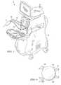
- FIG. 1illustrates a perspective view of one embodiment of a surgical system.
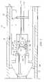
- FIG. 2illustrates a cross sectional view of one embodiment of a handpiece.
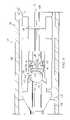
- FIG. 3illustrates a cross sectional view of one embodiment of a handpiece.
- FIG. 4illustrates a cross sectional view of one embodiment of a handpiece.
- FIG. 5illustrates a cross sectional view of one embodiment of a handpiece.
- FIG. 6illustrates a cross sectional view of one embodiment of a flow control member.
- Embodiments of the disclosureprovide apparatus and methods for cataract extraction.
- the terms “comprises,” “comprising,” “includes,” “including,” “has,” “having” or any other variation thereof,are intended to cover a non-exclusive inclusion.
- a process, process, article, or apparatus that comprises a list of elementsis not necessarily limited only those elements but may include other elements not expressly listed or inherent to such process, process, article, or apparatus.
- “or”refers to an inclusive or and not to an exclusive or. For example, a condition A or B is satisfied by any one of the following: A is true (or present) and B is false (or not present), A is false (or not present) and B is true (or present), and both A and B are true (or present).
- any examples or illustrations given hereinare not to be regarded in any way as restrictions on, limits to, or express definitions of, any term or terms with which they are utilized. Instead, these examples or illustrations are to be regarded as being described with respect to one particular embodiment and as illustrative only. Those of ordinary skill in the art will appreciate that any term or terms with which these examples or illustrations are utilized will encompass other embodiments which may or may not be given therewith or elsewhere in the specification and all such embodiments are intended to be included within the scope of that term or terms. Language designating such nonlimiting examples and illustrations includes, but is not limited to: “for example”, “for instance”, “e.g.”, “in one embodiment”.
- phacoemulsificationMany lenses affected by cataracts are removed by a surgical technique called phacoemulsification.
- a thin phacoemulsification cutting tipcan be inserted into the diseased lens and vibrated ultrasonically.
- the vibrating cutting tipliquefies or emulsifies the lens so that the lens may be aspirated out of the eye.
- the diseased lensonce removed, can be replaced by an artificial lens.
- a typical ultrasonic surgical device suitable for opthalmologic proceduresconsists of an ultrasonically driven handpiece, an attached cutting tip, irrigating sleeve, and an electronic control console in some embodiments.
- the handpiece assemblycan be attached to the control console by an electric cable and flexible tubes. Through the electric cable, the console can vary the power level transmitted by the handpiece to the attached cutting tip and the flexible tubes can supply irrigation fluid to, and draw aspiration fluid from, the eye through the handpiece assembly.
- the operative part of the handpiececan be a centrally located, hollow resonating bar or horn directly attached to a set of piezoelectric crystals.
- the crystalscan supply the required ultrasonic vibration needed to drive both the horn and the attached cutting tip during phacoemulsification and can be controlled by the console.
- the crystal/horn assemblycan be suspended within the hollow body or shell of the handpiece by flexible mountings.
- the handpiece bodyterminates in a reduced diameter portion or nosecone at the body's distal end.
- the noseconecan be externally threaded to accept the irrigation sleeve.
- the horn boreis internally threaded at its distal end to receive the external threads of the cutting tip.
- the irrigation sleevecan have an internally threaded bore that is screwed onto the external threads of the nosecone.
- the cutting tipcan be adjusted so that the tip projects only a predetermined amount past the open end of the irrigating sleeve.
- the ends of the cutting tip and irrigating sleevecan be inserted into a small incision of predetermined width in the cornea, sclera, or other location.
- the cutting tipcan be ultrasonically vibrated along its longitudinal axis within the irrigating sleeve by the crystal-driven ultrasonic horn, thereby emulsifying the selected tissue in situ.
- the hollow bore of the cutting tipcan communicate with the bore in the horn that in turn communicates with the aspiration line from the handpiece to the console.
- a reduced pressure or vacuum source in the consoledraws or can aspirate the emulsified tissue from the eye through the open end of the cutting tip, the cutting tip and horn bores and the aspiration line and into a collection device.
- the aspiration of emulsified tissuecan be aided by a saline flushing solution or irrigant that is injected into the surgical site through the small annular gap between the inside surface of the irrigating sleeve and the cutting tip.
- a cataract removal methodcan involve the injection of warm (approximately 45 degree Celsius to 105.degree Celsius) water or saline to liquefy or gellate the hard lens nucleus, thereby making it possible to aspirate the liquefied lens from the eye. Aspiration can be conducted concurrently with the injection of the heated solution and the injection of a relatively cool solution, thereby quickly cooling and removing the heated solution. In some embodiments, the apparatus, however, heats the solution separately from the surgical handpiece. Apparatus and methods for practicing cataract extraction using various liquefaction apparatus and techniques are disclosed in U.S. patent application Ser. No. 11/037,062, entitled Surgical System and Handpiece, by Dimalanta et al. and in U.S. Pat. No. 5,616,120, entitled Method And Apparatus For Lenticular Liquefaction And Aspiration, by Andrew et al. both of which are incorporated herein as if set forth in full.
- the AQUALASE® handpiecepart of the INFINITI® Vision System available from Alcon Laboratories, Inc., Fort Worth, Tex., produces pulses of warmed irrigation fluid for lens removal and cortical cleanup.
- Embodiments disclosed hereincan be used in conjunction with the AQUALASE, or other, handpieces.
- system 10can include one embodiment of control console 12 and handpiece 14 .
- System 10may be any suitable system, such as the INFINITI®. Vision System available from Alcon Laboratories, Inc., Fort Worth, Tex.
- Handpiece 14may be any suitable handpiece, such as the AQUALASE® handpiece available from Alcon Laboratories, Inc., Fort Worth, Tex.
- System 10can be connected to console 12 by fluid tubes 16 and 18 , and electrically connected to console 12 by electrical cable 20 .
- Control console 12can contain appropriate hardware and software (not shown, but well-known in the art) for providing control signals to handpiece 14 .
- embodiments of handpieces 14 for practicing liquefaction techniquesgenerally can include an aspiration line (connected to console 12 through tubing 18 ) and irrigation line 24 (connected to console 12 by tubing 16 ).
- Irrigation line 24can provide sterile irrigation fluid to pulse engine 26 .
- Pulse engine 26can contain proximal electrode 25 and distal electrode 27 to form boiling chamber 28 that produces pressurized pulses of irrigation fluid.
- Irrigation fluid boiled in chamber 28can exit pulse engine 26 through irrigation line 24 .
- the pressure of the pulse exiting pulse engine 26 through irrigation line 24can be determined by the size and duration of the electrical drive signal sent to pulse engine 26 through cable 20 by console 12 .
- handpiece 14includes check valve 30 with spring 29 and flow control member 32 which can bias check valve 30 closed.
- Handpiece 14can define valve chamber 33 in which check valve 30 can fit.
- Check valve 30can open when some positive differential pressure (a “cracking pressure”) is applied across it.
- a source of irrigation fluidfor instance, balanced saline solution (BSS)
- BSSbalanced saline solution
- the irrigation fluidcan flow past closed seat 48 from tube 16 to irrigation line 24 through upstream chamber portion 37 (which can connect tube 16 to check valve 32 ), flow path 46 (which can carry the BSS around flow control member 32 ), and downstream chamber portion 38 .
- BSSbalanced saline solution
- handpiece 114can include check valve 130 as illustrated by FIG. 3 .
- Check valve 130can “crack” (open) substantially without a differential pressure being applied across it, thereby obviating the need for a source of pressure (such as a bag(s) of irrigation fluid).
- check valve 130can close when pressure increases from pulse engine 128 reach it without including a spring or other biasing member.
- handpiece 114can include pulse engine 126 with proximal electrode 125 and distal electrode 127 (which form boiling chamber 128 and define irrigation line 124 ), check valve 130 , flow control member 132 , valve chamber 133 , insert 134 , tube adaptor 136 , upstream chamber portion 137 , downstream chamber portion 138 , socket 140 , apertures 144 , flow path 146 , closed seat 148 , open seat 150 , and outlet port 151 .
- Flow control member 132 and insert 134can cooperate to allow flow through flow path 146 when pulse engine 126 is not generating a pulse of irrigation fluid.
- Flow control member 132 and insert 134can cooperate to prevent flow through flow path 146 when pulse engine 126 is generating a pulse of irrigation fluid.
- flow control member 132 and insert 134can be shaped and dimensioned to fit within the volume provided for check valve 30 and spring 29 (see FIG. 2 ).
- tube adapter 136can be shaped and dimensioned so that (in conjunction with flow control member 132 , insert 134 , and various features of handpiece 114 ) tube adapter 136 can hold components 116 and 132 in operative relationship to each other (as will be described with more specificity herein).
- tube adapter 136can be adapted to receive and retain irrigation tube 116 .
- Proximal electrode 125can define an inlet port adjacent to upstream chamber portion 137 of valve chamber 133 .
- tube adapter 136can be shaped and dimensioned to fit within the inlet port of proximal electrode 125 .
- Various features of proximal electrode 125can retain tube adapter 136 in the inlet port.
- Flow control member 132can determine, by its position, whether check valve 130 is open or closed. Flow control member 132 can be positioned in valve chamber 133 toward upstream chamber portion 137 and generally adjacent to tube adaptor 136 . In the open position shown in FIG. 3 , flow control member 132 can be distance d 1 (see FIG. 6 ) downstream of tube adaptor 136 and can abut open seat 150 . Open seat 150 and flow control member 132 can be shaped and dimensioned in such a manner to align flow control member 132 with open seat 150 , thereby improving closing speed and efficiency. In the closed position, flow control member 132 can abut closed seat 148 on the distal end of tube adaptor 136 . Thus, flow control member 132 is movable between open and closed positions.
- Distance d 1 between flow control member's 132 open and closed positionscan be about 0.001′′ to about 0.010′′ for a handpiece 114 shaped and dimensioned to be grasp by surgical personnel. In some embodiments, distance d 1 can be about 0.002′′ to about 0.003′′.
- Flow control member 132can be spherical and can partially fit in socket 140 of insert 134 . As shown in FIG. 3 , a sector of about 120 degrees of a particular spherical flow control member 132 can fit in socket 140 .
- Flow path 146 from upstream chamber portion 137 to downstream portion 138can be formed in proximal electrode 125 as an annulus around flow control member 132 and around an upstream portion of insert 134 .
- Flow path 146can communicate with apertures 144 positioned about the circumference of insert 134 and (through apertures 144 ) with downstream chamber portion 138 .
- Insert 134can be generally adjacent to and downstream from flow control member 132 .
- Insert 134(together with flow control member 132 ) can be shaped and dimensioned to fit within valve chamber 133 .
- Insert 134can be generally cylindrical and can define apertures 144 , socket 140 , and downstream chamber portion 138 .
- Downstream chamber portion 138can allow communication from irrigation line 124 to flow control member 132 , apertures 144 , and flow path 146 .
- check valve 130can allow flow passing over flow control member 132 and closed seat 148 , from irrigation tube 116 to outlet port 151 through tube adaptor 136 , flow path 146 , apertures 144 , downstream chamber portion 138 , boiling chamber 128 and irrigation line 124 .
- flow control member 132can abut closed seat 148 , thereby preventing communication between upper chamber portion 137 and flow path 146 .
- Flow control member 132can be generally adjacent to, but spaced apart from open seat 150 by distance d 1 when in the closed position.
- communicationcan be allowed from boiling chamber 128 , through downstream chamber portion 138 , through apertures 144 , and into flow path 146 .
- Communication from boiling chamber 128 to the downstream side of flow control member 132can be allowed via irrigation line 124 , downstream chamber portion 138 , and socket 140 .
- Flow from flow path 146 passing over closed seat 148 and flow control member 132 , and into upstream chamber portion 137can be prevented by flow control member 132 in the closed position.
- flow control member 132When in the open position illustrated by FIG. 3 , flow control member 132 can be moved to the closed position illustrated by FIG. 4 as follows.
- pulse 152 from boiling chamber 128can communicate through irrigation line 124 both upstream and downstream from boiling chamber 128 .
- Pulse 152can communicate through downstream chamber portion 138 to the vicinity of apertures 144 . Near apertures 144 , pulse 152 can split with pulse portion 154 communicating through apertures 144 to flow path 146 .
- Another pulse portion 156 of pulse 152can continue moving through downstream chamber portion 138 toward socket 140 and flow control member 132 .
- pulse portion 156can reach flow control member 132 relatively rapidly. At the downstream side of flow control member 132 , pulse portion 156 can urge flow control member 132 away from open seat 150 and toward closed seat 148 across distance d 1 (see FIG. 6 ). At some time, flow control member 132 can reach closed seat 148 , thereby preventing communication from flow path 146 to upper chamber portion 137 .
- pulse portion 154(which communicated through apertures 144 ) can be communicating upstream through flow path 146 .
- flow-retarding features it encounterscan retard its speed.
- pulse portion 154can turn at least twice (once in downstream chamber portion 138 to reach apertures 144 and once upstream of apertures 144 to turn into flow path 146 ).
- Aperture 144can be sharp edged thereby retarding communication of pulse portion 154 due to orifice effects of apertures 144 .
- Flow path 146can be a relatively narrow annulus between proximal electrode 125 and insert 134 , thereby retarding pulse portion 154 communication along flow path 146 .
- Narrowing of flow path 146 between flow control member 132 and proximal electrode 125can retard communication of pulse portion 154 also.
- pulse portion 154 passing flow control member 132can turn toward open seat 150 , thereby further retarding communication of pulse portion 154 .
- substantially all of pulse 152 from boiling chamber 128can be directed downstream and out of outlet port 151 at some time.
- pulse portion 156(which communicated upstream) can reflect from check valve 130 and subsequently communicate out of output port 151 through irrigation line 124 .
- Substantially all of pulse 152may therefore be directed at tissue which surgical personnel may wish to liquefy and extract.
- irrigation line 124 , boiling chamber 128 , flow control member 132 , downstream chamber portion 138 , socket 140 , apertures 144 , flow path 146 , closed seat 148 , and open seat 150can be shaped and dimensioned as a fluid system to select a time-varying profile of pulse 152 communicating to the distal end of irrigation line 124 .
- flow control member 132 and insert 134can be shaped and dimensioned to fit within the volume occupied by check valve 30 including spring 29 (see FIG. 2 ).
- handpieces 14 of FIG. 2can be converted to include check valves 130 (without springs 29 or other biasing members). More particularly, handpiece 14 can be converted by removing the ball and spring 29 of check valve 30 from handpiece 14 and inserting insert 134 into handpiece 14 with socket 140 pointing toward the proximal end of handpiece 14 .
- Flow control member 132can be inserted into handpiece 14 and socket 140 (of insert 134 ).
- Tube adapter 136can be inserted into valve handpiece 14 to enclose check valve 130 in handpiece 14 (converted to include spring-less check valve 130 ).
- Handpiece 214can include pulse engine electrodes 225 and 227 , handpiece cap 219 , pulse engine projection 221 , irrigation line 224 , pulse engine 226 , boiling chamber 228 , check valve 230 , flow control member 232 , inlet port 236 , upstream chamber portion 237 , downstream chamber portion 238 , socket 240 , apertures 244 , flow path 246 , closed seat 248 , open seat 250 , and outlet port 251 .
- Handpiece cap 219can define upstream chamber portion 237 and closed seat 248 .
- Handpiece body 214can include pulse engine projection 221 extending from its distal end.
- Pulse engine projection 221can define downstream chamber portion 238 , socket 240 , and apertures 244 . Apertures 244 can be formed in pulse engine projection 221 and can be in communication with flow path 246 and downstream chamber portion 238 . Pulse engine projection 221 can define open seat 250 . Pulse engine projection 221 , in some embodiments, can be formed integrally with pulse engine electrode 217 . Thus, pulse engine projection 221 can be made from the same material as pulse engine electrode 217 which can be a conductive and corrosion resistant metal in some embodiments.
- Handpiece cap 219can define upstream chamber portion 237 and closed seat 248 .
- handpiece cap 219can define flow path 246 including a 90 degree turn adjacent to, and downstream from, flow control member 232 .
- Handpiece cap 219can couple to, and seal against, pulse engine projection 221 at coupling interface 253 which can include threads or other features for this purpose.
- handpiece cap 219 and pulse engine projection 221can retain flow control member 232 in valve chamber 233 while allowing flow control member 232 to move between its open and closed positions.
- check valve 230 of handpiece 214can prevent flow through flow path 246 when flow control member 232 is in its closed position and can allow flow through flow path 246 when flow control member 232 is in its open position. By moving between its open and closed positions, flow control member 232 can determine whether check valve 130 is open or closed.
- Embodimentsprovide advantages over previously available handpieces.
- Various embodimentsprovide handpiece check valves which can crack open substantially without an applied positive differential pressure.
- Embodimentsprovide check valves with fewer moving parts than previously available. Hence, embodiments provide handpieces with higher reliability than previously available handpieces.
Landscapes
- Health & Medical Sciences (AREA)
- Life Sciences & Earth Sciences (AREA)
- General Health & Medical Sciences (AREA)
- Veterinary Medicine (AREA)
- Engineering & Computer Science (AREA)
- Biomedical Technology (AREA)
- Heart & Thoracic Surgery (AREA)
- Animal Behavior & Ethology (AREA)
- Public Health (AREA)
- Anesthesiology (AREA)
- Hematology (AREA)
- Ophthalmology & Optometry (AREA)
- Nuclear Medicine, Radiotherapy & Molecular Imaging (AREA)
- Vascular Medicine (AREA)
- Surgery (AREA)
- Physics & Mathematics (AREA)
- Fluid Mechanics (AREA)
- Surgical Instruments (AREA)
Abstract
Description
Claims (17)
Priority Applications (6)
| Application Number | Priority Date | Filing Date | Title |
|---|---|---|---|
| US12/237,468US8291933B2 (en) | 2008-09-25 | 2008-09-25 | Spring-less check valve for a handpiece |
| AU2009296817AAU2009296817B2 (en) | 2008-09-25 | 2009-09-21 | Spring-less check valve for a handpiece |
| JP2011529147AJP2012503525A (en) | 2008-09-25 | 2009-09-21 | Check valve for handpiece without spring |
| CA 2736896CA2736896A1 (en) | 2008-09-25 | 2009-09-21 | Spring-less check valve for a handpiece |
| PCT/US2009/057675WO2010036610A1 (en) | 2008-09-25 | 2009-09-21 | Spring-less check valve for a handpiece |
| EP20090792775EP2344097A1 (en) | 2008-09-25 | 2009-09-21 | Spring-less check valve for a handpiece |
Applications Claiming Priority (1)
| Application Number | Priority Date | Filing Date | Title |
|---|---|---|---|
| US12/237,468US8291933B2 (en) | 2008-09-25 | 2008-09-25 | Spring-less check valve for a handpiece |
Publications (2)
| Publication Number | Publication Date |
|---|---|
| US20100076471A1 US20100076471A1 (en) | 2010-03-25 |
| US8291933B2true US8291933B2 (en) | 2012-10-23 |
Family
ID=41278299
Family Applications (1)
| Application Number | Title | Priority Date | Filing Date |
|---|---|---|---|
| US12/237,468Active2031-05-14US8291933B2 (en) | 2008-09-25 | 2008-09-25 | Spring-less check valve for a handpiece |
Country Status (6)
| Country | Link |
|---|---|
| US (1) | US8291933B2 (en) |
| EP (1) | EP2344097A1 (en) |
| JP (1) | JP2012503525A (en) |
| AU (1) | AU2009296817B2 (en) |
| CA (1) | CA2736896A1 (en) |
| WO (1) | WO2010036610A1 (en) |
Cited By (1)
| Publication number | Priority date | Publication date | Assignee | Title |
|---|---|---|---|---|
| US20130317417A1 (en)* | 2012-05-25 | 2013-11-28 | Abbott Medical Optics Inc. | Surgical handpiece having directional fluid control capabilities |
Families Citing this family (3)
| Publication number | Priority date | Publication date | Assignee | Title |
|---|---|---|---|---|
| US8291933B2 (en) | 2008-09-25 | 2012-10-23 | Novartis Ag | Spring-less check valve for a handpiece |
| US8568396B2 (en)* | 2009-12-10 | 2013-10-29 | Alcon Research, Ltd. | Flooded liquefaction hand piece engine |
| US9878075B2 (en)* | 2012-12-10 | 2018-01-30 | Alcon Research, Ltd. | Vacuum control method for surgical hand piece |
Citations (118)
| Publication number | Priority date | Publication date | Assignee | Title |
|---|---|---|---|---|
| US121697A (en) | 1871-12-05 | William h | ||
| US294334A (en) | 1884-02-26 | loetzee | ||
| US351159A (en) | 1886-10-19 | Jacob bbengel | ||
| US865631A (en) | 1906-11-26 | 1907-09-10 | Frank P Cotter | Check-valve. |
| US2121936A (en) | 1934-05-01 | 1938-06-28 | Phillips Petroleum Co | Combination excess flow and check valve |
| US2386765A (en)* | 1944-04-18 | 1945-10-16 | E A R Inc | Internal-combustion engine charge forming device |
| US2536836A (en) | 1947-05-05 | 1951-01-02 | Leonard C Bowling | Valve |
| US2623725A (en) | 1946-10-30 | 1952-12-30 | Asa D Sands | Safety valve |
| US2755816A (en)* | 1949-05-07 | 1956-07-24 | Collins Valve Company Inc | Check valves |
| US3085589A (en) | 1960-06-06 | 1963-04-16 | Asa D Sands | Safety valve |
| US3191807A (en) | 1961-11-13 | 1965-06-29 | Microchemical Specialties Co | Dispenser adapted for ultra-micro range |
| US3336942A (en) | 1964-07-28 | 1967-08-22 | Garland B Keith | Check valve |
| US3561471A (en) | 1968-10-29 | 1971-02-09 | Asa D Sands | Safety valve |
| US3589363A (en) | 1967-07-25 | 1971-06-29 | Cavitron Corp | Material removal apparatus and method employing high frequency vibrations |
| US3693613A (en) | 1970-12-09 | 1972-09-26 | Cavitron Corp | Surgical handpiece and flow control system for use therewith |
| US3756270A (en) | 1972-04-25 | 1973-09-04 | Monocar Hc Internacional Sa | Auxiliary anti pollution air intake device for internal combustion engines |
| US3818913A (en) | 1972-08-30 | 1974-06-25 | M Wallach | Surgical apparatus for removal of tissue |
| US4018247A (en) | 1975-02-28 | 1977-04-19 | Carr Clifford H | Springless ball valve for high speed compressors |
| US4030520A (en) | 1976-08-05 | 1977-06-21 | Sands Asa D | Ball-type safety valve |
| US4095580A (en) | 1976-10-22 | 1978-06-20 | The United States Of America As Represented By The United States Department Of Energy | Pulse-actuated fuel-injection spark plug |
| US4156187A (en) | 1977-03-15 | 1979-05-22 | Fibra-Sonics, Inc. | Device and method for measuring and indicating the true power supplied to an ultrasonic handpiece and for recording the accumulative power applied to the handpiece |
| US4155374A (en) | 1977-09-22 | 1979-05-22 | Deere & Company | Internal check ball retainer |
| US4168707A (en) | 1977-06-13 | 1979-09-25 | Douvas Nicholas G | Control apparatus for microsurgical instruments |
| US4223676A (en) | 1977-12-19 | 1980-09-23 | Cavitron Corporation | Ultrasonic aspirator |
| US4229149A (en)* | 1978-08-28 | 1980-10-21 | Turner Richard L | Oil well pump |
| US4246902A (en) | 1978-03-10 | 1981-01-27 | Miguel Martinez | Surgical cutting instrument |
| US4274411A (en) | 1979-03-30 | 1981-06-23 | Dotson Robert S Jun | Fluid operated ophthalmic irrigation and aspiration device |
| US4380911A (en) | 1981-08-05 | 1983-04-26 | Zumbiel William A | Refrigeration control apparatus |
| US4493694A (en) | 1980-10-17 | 1985-01-15 | Cooper Lasersonics, Inc. | Surgical pre-aspirator |
| US4515583A (en) | 1983-10-17 | 1985-05-07 | Coopervision, Inc. | Operative elliptical probe for ultrasonic surgical instrument and method of its use |
| US4570669A (en) | 1982-08-24 | 1986-02-18 | Pauliukonis Richard S | Simplified springless check valve |
| US4589415A (en) | 1984-08-31 | 1986-05-20 | Haaga John R | Method and system for fragmenting kidney stones |
| US4609368A (en) | 1984-08-22 | 1986-09-02 | Dotson Robert S Jun | Pneumatic ultrasonic surgical handpiece |
| US4655247A (en) | 1986-01-17 | 1987-04-07 | Chromalloy American Corporation | Ball-type check valve assembly |
| US4657490A (en) | 1985-03-27 | 1987-04-14 | Quest Medical, Inc. | Infusion pump with disposable cassette |
| US4668231A (en) | 1984-02-15 | 1987-05-26 | Cordis Corporation | Implantable hand-operable dispensers for fluid medicaments |
| US4784652A (en) | 1985-03-27 | 1988-11-15 | Fagersta El & Diesel Ab | Eyewash dispenser |
| US4797098A (en) | 1987-04-22 | 1989-01-10 | Nakanishi Dental Mfg. Co., Ltd. | Apparatus for dental treatment provided with check valve in fluid passage |
| US4869715A (en) | 1988-04-21 | 1989-09-26 | Sherburne Fred S | Ultrasonic cone and method of construction |
| US4909783A (en) | 1986-07-16 | 1990-03-20 | Morrison David P | Intra-ocular pressure apparatus |
| US4921477A (en) | 1987-10-14 | 1990-05-01 | The Cooper Companies, Inc. | Surgical irrigation and aspiration system with dampening device |
| US4922902A (en) | 1986-05-19 | 1990-05-08 | Valleylab, Inc. | Method for removing cellular material with endoscopic ultrasonic aspirator |
| US4935005A (en) | 1985-06-05 | 1990-06-19 | Nestle, S.A. | Opthalmic fluid flow control system |
| US4989583A (en) | 1988-10-21 | 1991-02-05 | Nestle S.A. | Ultrasonic cutting tip assembly |
| US5061241A (en) | 1989-01-19 | 1991-10-29 | Stephens Jr Harry W | Rapid infusion device |
| US5152753A (en) | 1990-04-02 | 1992-10-06 | Pudenz-Schulte Medical Research Corporation | Medication infusion device with dose recharge restriction |
| US5154694A (en) | 1989-06-06 | 1992-10-13 | Kelman Charles D | Tissue scraper device for medical use |
| US5261883A (en) | 1990-10-26 | 1993-11-16 | Alcon Surgical, Inc. | Portable apparatus for controlling fluid flow to a surgical site |
| US5322504A (en) | 1992-05-07 | 1994-06-21 | United States Surgical Corporation | Method and apparatus for tissue excision and removal by fluid jet |
| US5358150A (en) | 1990-07-03 | 1994-10-25 | Mpl Technologies, Inc. | Pressurized fluid dispensing device |
| US5380280A (en) | 1993-11-12 | 1995-01-10 | Peterson; Erik W. | Aspiration system having pressure-controlled and flow-controlled modes |
| US5514088A (en) | 1986-06-09 | 1996-05-07 | Development Collaborative Corporation | Apparatus, and method for chemical contact dissolution of gallstones |
| US5514110A (en) | 1993-03-22 | 1996-05-07 | Teh; Eutiquio L. | Automatic flow control device |
| US5562692A (en) | 1993-07-26 | 1996-10-08 | Sentinel Medical, Inc. | Fluid jet surgical cutting tool |
| US5577533A (en) | 1994-09-13 | 1996-11-26 | Cook, Jr.; Joseph S. | Flexured shaft poppet |
| US5580347A (en) | 1991-07-31 | 1996-12-03 | Mentor Ophthalmics, Inc. | Controlling operation of handpieces during ophthalmic surgery |
| US5616120A (en) | 1995-02-06 | 1997-04-01 | Andrew; Mark S. | Method and apparatus for lenticular liquefaction and aspiration |
| US5735815A (en) | 1993-07-26 | 1998-04-07 | Sentinel Medical, Inc. | Method of using fluid jet surgical cutting tool |
| US5741229A (en) | 1988-03-08 | 1998-04-21 | Scimed Life Systems, Inc. | Balloon catheter inflation device |
| US5865790A (en) | 1993-07-26 | 1999-02-02 | Surgijet, Inc. | Method and apparatus for thermal phacoemulsification by fluid throttling |
| US5885243A (en) | 1996-12-11 | 1999-03-23 | Alcon Laboratories, Inc. | Liquefaction handpiece |
| US5989212A (en) | 1998-06-04 | 1999-11-23 | Alcon Laboratories, Inc. | Pumping chamber for a liquefaction handpiece having a countersink electrode |
| US5997499A (en) | 1998-06-04 | 1999-12-07 | Alcon Laboratories, Inc. | Tip for a liquefaction handpiece |
| US6004284A (en) | 1998-06-04 | 1999-12-21 | Alcon Laboratories, Inc. | Surgical handpiece |
| US6080128A (en) | 1998-06-04 | 2000-06-27 | Alcon Laboratories, Inc. | Liquefaction handpiece |
| US6123101A (en) | 1997-05-14 | 2000-09-26 | Magne-Flo Corporation | Spring body excess flow valve |
| US6155975A (en) | 1998-11-06 | 2000-12-05 | Urich; Alex | Phacoemulsification apparatus with personal computer |
| US6179805B1 (en) | 1998-06-04 | 2001-01-30 | Alcon Laboratories, Inc. | Liquefracture handpiece |
| US6179808B1 (en) | 1999-06-18 | 2001-01-30 | Alcon Laboratories, Inc. | Method of controlling the operating parameters of a surgical system |
| US6186148B1 (en) | 1998-02-04 | 2001-02-13 | Kiyoshi Okada | Prevention of posterior capsular opacification |
| US6196989B1 (en) | 1998-06-04 | 2001-03-06 | Alcon Laboratories, Inc. | Tip for liquefracture handpiece |
| US6206848B1 (en) | 1998-06-04 | 2001-03-27 | Alcon Laboratories, Inc. | Liquefracture handpiece |
| US6241700B1 (en) | 1999-03-08 | 2001-06-05 | Alcon Laboratories, Inc. | Surgical handpiece |
| US6258111B1 (en) | 1997-10-03 | 2001-07-10 | Scieran Technologies, Inc. | Apparatus and method for performing ophthalmic procedures |
| US6315755B1 (en) | 1998-06-04 | 2001-11-13 | Alcon Manufacturing, Ltd. | Method of controlling a liquefracture handpiece |
| US6331171B1 (en) | 1998-06-04 | 2001-12-18 | Alcon Laboratories, Inc. | Tip for a liquefracture handpiece |
| US20020013572A1 (en) | 2000-05-19 | 2002-01-31 | Berlin Michael S. | Delivery system and method of use for the eye |
| EP1199054A1 (en) | 2000-10-17 | 2002-04-24 | Alcon Manufacturing Ltd. | Liquefracture handpiece tip |
| US6425883B1 (en) | 1998-05-08 | 2002-07-30 | Circuit Tree Medical, Inc. | Method and apparatus for controlling vacuum as a function of ultrasonic power in an ophthalmic phaco aspirator |
| US6440103B1 (en) | 1999-03-17 | 2002-08-27 | Surgijet, Inc. | Method and apparatus for thermal emulsification |
| US20020161326A1 (en) | 1998-06-04 | 2002-10-31 | Glenn Sussman | Tip for a liquefracture handpiece |
| US20020188261A1 (en) | 2001-06-07 | 2002-12-12 | Dermacel Inc. | Hand piece for use in a dermal abrasion system |
| US6513545B2 (en) | 2001-01-16 | 2003-02-04 | Evan M. Rhone | Safety valve with adjustable maximum flow shut off mechanism |
| US6575929B2 (en) | 2000-03-14 | 2003-06-10 | Alcon Manufacturing, Ltd. | Pumping chamber for a liquefaction handpiece |
| US6575990B1 (en) | 1999-10-21 | 2003-06-10 | Medical Instrument Development Laboratories, Inc. | High speed vitreous cutting system |
| US6579270B2 (en) | 1998-06-04 | 2003-06-17 | Alcon Manufacturing, Ltd. | Liquefracture handpiece tip |
| US6589201B1 (en) | 1998-06-04 | 2003-07-08 | Alcon Manufacturing, Ltd. | Liquefracture handpiece tip |
| US6623477B1 (en) | 1998-11-06 | 2003-09-23 | Asclepion-Meditec Ag | Medical instrument for phacoemulsification |
| US6648847B2 (en) | 1998-06-04 | 2003-11-18 | Alcon Manufacturing, Ltd. | Method of operating a liquefracture handpiece |
| US20040024380A1 (en) | 2002-08-05 | 2004-02-05 | Darnell Lawrence W. | Container for delivery of fluid to ophthalmic surgical handpiece |
| US6796957B2 (en) | 2001-07-10 | 2004-09-28 | Myocardial Therapeutics, Inc. | Sterile aspiration/reinjection systems |
| US6830064B2 (en) | 2000-12-29 | 2004-12-14 | Chang-Hyeon Ji | Leak control valve |
| US6860868B1 (en) | 1998-06-04 | 2005-03-01 | Alcon Manufacturing, Ltd. | Surgical handpiece |
| US6892756B2 (en) | 2000-09-06 | 2005-05-17 | Mertik Maxitrol Gmbh & Co. Kg | Gas flow monitoring device |
| US6920895B2 (en) | 2001-04-16 | 2005-07-26 | Alan Avis | Combination surge supression and safety shut-off valve |
| US6921385B2 (en) | 2002-08-05 | 2005-07-26 | Alcon, Inc. | Apparatus for delivery of fluid to opthalmic surgical handpiece |
| US6953052B2 (en) | 2001-06-27 | 2005-10-11 | Wartsila Technology Oy Ab | Fuel system shut-off valve |
| US20050228423A1 (en) | 2003-02-14 | 2005-10-13 | Alcon, Inc. | Apparatus and method for determining that a surgical fluid container is near empty |
| US20050228424A1 (en) | 2003-02-14 | 2005-10-13 | Alcon, Inc. | Apparatus and method for determining that a surgical fluid container is near empty |
| US20060058823A1 (en) | 2004-09-14 | 2006-03-16 | Dimalanta Ramon C | Handpiece pumping chamber |
| US20060161101A1 (en)* | 2005-01-18 | 2006-07-20 | Alcon, Inc. | Surgical system and handpiece |
| US20060173403A1 (en) | 2005-01-28 | 2006-08-03 | Alcon, Inc. | Variable flow device |
| US20060184091A1 (en) | 2005-02-14 | 2006-08-17 | Alcon, Inc. | Liquefaction handpiece |
| US20060212039A1 (en) | 2005-03-16 | 2006-09-21 | Alcon, Inc. | Pumping chamber for a liquefaction handpiece |
| US20060212037A1 (en)* | 2005-03-16 | 2006-09-21 | Alcon, Inc. | Pumping chamber for a liquefaction handpiece |
| US20060224116A1 (en) | 2005-03-16 | 2006-10-05 | Alcon, Inc. | Pumping chamber for a liquefaction handpiece |
| US20080077077A1 (en) | 2006-09-26 | 2008-03-27 | Williams David L | Valve that is normally closed in the free state |
| US20080073906A1 (en) | 2006-09-26 | 2008-03-27 | Turner Denis P | Dual fluid connector |
| US20080082077A1 (en) | 2006-09-29 | 2008-04-03 | David Lloyd Williams | System and method for flow rate control |
| US20080086093A1 (en) | 2006-09-18 | 2008-04-10 | Steppe Dennis L | Automatic stop cock valve |
| US20080125697A1 (en) | 2006-09-14 | 2008-05-29 | Alcon, Inc. | Method of controlling an irrigation/aspiration system |
| US20090032121A1 (en) | 2007-07-31 | 2009-02-05 | Chon James Y | Check Valve |
| US20090032123A1 (en) | 2007-07-31 | 2009-02-05 | Bourne John M | Check Valve |
| US20090068870A1 (en) | 2007-08-08 | 2009-03-12 | Mezhinsky Victor B | Floating self-centering connector |
| US7509831B2 (en) | 2007-05-25 | 2009-03-31 | Alcon, Inc. | Method for determining a pressure that corresponds to a flow rate through a check valve |
| US7535815B2 (en) | 2002-12-19 | 2009-05-19 | Koninklijke Philips Electronics N.V. | Disc drive apparatus |
| WO2010036610A1 (en) | 2008-09-25 | 2010-04-01 | Alcon, Inc. | Spring-less check valve for a handpiece |
| US7789069B2 (en)* | 2007-01-17 | 2010-09-07 | Robert Bosch Gmbh | Check valve, and injector with hydraulic booster and check valve |
Family Cites Families (1)
| Publication number | Priority date | Publication date | Assignee | Title |
|---|---|---|---|---|
| JPS60129566U (en)* | 1984-02-10 | 1985-08-30 | 株式会社小松製作所 | non-return valve |
- 2008
- 2008-09-25USUS12/237,468patent/US8291933B2/enactiveActive
- 2009
- 2009-09-21EPEP20090792775patent/EP2344097A1/ennot_activeWithdrawn
- 2009-09-21WOPCT/US2009/057675patent/WO2010036610A1/enactiveApplication Filing
- 2009-09-21CACA 2736896patent/CA2736896A1/ennot_activeAbandoned
- 2009-09-21AUAU2009296817Apatent/AU2009296817B2/ennot_activeExpired - Fee Related
- 2009-09-21JPJP2011529147Apatent/JP2012503525A/enactivePending
Patent Citations (130)
| Publication number | Priority date | Publication date | Assignee | Title |
|---|---|---|---|---|
| US121697A (en) | 1871-12-05 | William h | ||
| US294334A (en) | 1884-02-26 | loetzee | ||
| US351159A (en) | 1886-10-19 | Jacob bbengel | ||
| US865631A (en) | 1906-11-26 | 1907-09-10 | Frank P Cotter | Check-valve. |
| US2121936A (en) | 1934-05-01 | 1938-06-28 | Phillips Petroleum Co | Combination excess flow and check valve |
| US2386765A (en)* | 1944-04-18 | 1945-10-16 | E A R Inc | Internal-combustion engine charge forming device |
| US2623725A (en) | 1946-10-30 | 1952-12-30 | Asa D Sands | Safety valve |
| US2536836A (en) | 1947-05-05 | 1951-01-02 | Leonard C Bowling | Valve |
| US2755816A (en)* | 1949-05-07 | 1956-07-24 | Collins Valve Company Inc | Check valves |
| US3085589A (en) | 1960-06-06 | 1963-04-16 | Asa D Sands | Safety valve |
| US3191807A (en) | 1961-11-13 | 1965-06-29 | Microchemical Specialties Co | Dispenser adapted for ultra-micro range |
| US3336942A (en) | 1964-07-28 | 1967-08-22 | Garland B Keith | Check valve |
| US3589363A (en) | 1967-07-25 | 1971-06-29 | Cavitron Corp | Material removal apparatus and method employing high frequency vibrations |
| US3561471A (en) | 1968-10-29 | 1971-02-09 | Asa D Sands | Safety valve |
| US3693613A (en) | 1970-12-09 | 1972-09-26 | Cavitron Corp | Surgical handpiece and flow control system for use therewith |
| US3756270A (en) | 1972-04-25 | 1973-09-04 | Monocar Hc Internacional Sa | Auxiliary anti pollution air intake device for internal combustion engines |
| US3818913A (en) | 1972-08-30 | 1974-06-25 | M Wallach | Surgical apparatus for removal of tissue |
| US4018247A (en) | 1975-02-28 | 1977-04-19 | Carr Clifford H | Springless ball valve for high speed compressors |
| US4030520A (en) | 1976-08-05 | 1977-06-21 | Sands Asa D | Ball-type safety valve |
| US4095580A (en) | 1976-10-22 | 1978-06-20 | The United States Of America As Represented By The United States Department Of Energy | Pulse-actuated fuel-injection spark plug |
| US4156187A (en) | 1977-03-15 | 1979-05-22 | Fibra-Sonics, Inc. | Device and method for measuring and indicating the true power supplied to an ultrasonic handpiece and for recording the accumulative power applied to the handpiece |
| US4168707A (en) | 1977-06-13 | 1979-09-25 | Douvas Nicholas G | Control apparatus for microsurgical instruments |
| US4155374A (en) | 1977-09-22 | 1979-05-22 | Deere & Company | Internal check ball retainer |
| US4223676A (en) | 1977-12-19 | 1980-09-23 | Cavitron Corporation | Ultrasonic aspirator |
| US4246902A (en) | 1978-03-10 | 1981-01-27 | Miguel Martinez | Surgical cutting instrument |
| US4229149A (en)* | 1978-08-28 | 1980-10-21 | Turner Richard L | Oil well pump |
| US4274411A (en) | 1979-03-30 | 1981-06-23 | Dotson Robert S Jun | Fluid operated ophthalmic irrigation and aspiration device |
| US4493694A (en) | 1980-10-17 | 1985-01-15 | Cooper Lasersonics, Inc. | Surgical pre-aspirator |
| US4380911A (en) | 1981-08-05 | 1983-04-26 | Zumbiel William A | Refrigeration control apparatus |
| US4570669A (en) | 1982-08-24 | 1986-02-18 | Pauliukonis Richard S | Simplified springless check valve |
| US4515583A (en) | 1983-10-17 | 1985-05-07 | Coopervision, Inc. | Operative elliptical probe for ultrasonic surgical instrument and method of its use |
| US4668231A (en) | 1984-02-15 | 1987-05-26 | Cordis Corporation | Implantable hand-operable dispensers for fluid medicaments |
| US4609368A (en) | 1984-08-22 | 1986-09-02 | Dotson Robert S Jun | Pneumatic ultrasonic surgical handpiece |
| US4589415A (en) | 1984-08-31 | 1986-05-20 | Haaga John R | Method and system for fragmenting kidney stones |
| US4657490A (en) | 1985-03-27 | 1987-04-14 | Quest Medical, Inc. | Infusion pump with disposable cassette |
| US4784652A (en) | 1985-03-27 | 1988-11-15 | Fagersta El & Diesel Ab | Eyewash dispenser |
| US4935005A (en) | 1985-06-05 | 1990-06-19 | Nestle, S.A. | Opthalmic fluid flow control system |
| US4655247A (en) | 1986-01-17 | 1987-04-07 | Chromalloy American Corporation | Ball-type check valve assembly |
| US4922902A (en) | 1986-05-19 | 1990-05-08 | Valleylab, Inc. | Method for removing cellular material with endoscopic ultrasonic aspirator |
| US5514088A (en) | 1986-06-09 | 1996-05-07 | Development Collaborative Corporation | Apparatus, and method for chemical contact dissolution of gallstones |
| US4909783A (en) | 1986-07-16 | 1990-03-20 | Morrison David P | Intra-ocular pressure apparatus |
| US4797098A (en) | 1987-04-22 | 1989-01-10 | Nakanishi Dental Mfg. Co., Ltd. | Apparatus for dental treatment provided with check valve in fluid passage |
| US4921477A (en) | 1987-10-14 | 1990-05-01 | The Cooper Companies, Inc. | Surgical irrigation and aspiration system with dampening device |
| US5741229A (en) | 1988-03-08 | 1998-04-21 | Scimed Life Systems, Inc. | Balloon catheter inflation device |
| US4869715A (en) | 1988-04-21 | 1989-09-26 | Sherburne Fred S | Ultrasonic cone and method of construction |
| US5359996A (en) | 1988-10-21 | 1994-11-01 | Nestle, S.A. | Ultrasonic cutting tip and assembly |
| US4989583A (en) | 1988-10-21 | 1991-02-05 | Nestle S.A. | Ultrasonic cutting tip assembly |
| US5061241A (en) | 1989-01-19 | 1991-10-29 | Stephens Jr Harry W | Rapid infusion device |
| US5154694A (en) | 1989-06-06 | 1992-10-13 | Kelman Charles D | Tissue scraper device for medical use |
| US5152753A (en) | 1990-04-02 | 1992-10-06 | Pudenz-Schulte Medical Research Corporation | Medication infusion device with dose recharge restriction |
| US5358150A (en) | 1990-07-03 | 1994-10-25 | Mpl Technologies, Inc. | Pressurized fluid dispensing device |
| US5261883A (en) | 1990-10-26 | 1993-11-16 | Alcon Surgical, Inc. | Portable apparatus for controlling fluid flow to a surgical site |
| US5580347A (en) | 1991-07-31 | 1996-12-03 | Mentor Ophthalmics, Inc. | Controlling operation of handpieces during ophthalmic surgery |
| US5322504A (en) | 1992-05-07 | 1994-06-21 | United States Surgical Corporation | Method and apparatus for tissue excision and removal by fluid jet |
| US5514110A (en) | 1993-03-22 | 1996-05-07 | Teh; Eutiquio L. | Automatic flow control device |
| US5865790A (en) | 1993-07-26 | 1999-02-02 | Surgijet, Inc. | Method and apparatus for thermal phacoemulsification by fluid throttling |
| US5735815A (en) | 1993-07-26 | 1998-04-07 | Sentinel Medical, Inc. | Method of using fluid jet surgical cutting tool |
| US5562692A (en) | 1993-07-26 | 1996-10-08 | Sentinel Medical, Inc. | Fluid jet surgical cutting tool |
| US5853384A (en) | 1993-07-26 | 1998-12-29 | Surgijet, Inc. | Fluid jet surgical cutting tool and aspiration device |
| US5380280A (en) | 1993-11-12 | 1995-01-10 | Peterson; Erik W. | Aspiration system having pressure-controlled and flow-controlled modes |
| US5577533A (en) | 1994-09-13 | 1996-11-26 | Cook, Jr.; Joseph S. | Flexured shaft poppet |
| US5616120A (en) | 1995-02-06 | 1997-04-01 | Andrew; Mark S. | Method and apparatus for lenticular liquefaction and aspiration |
| US5885243A (en) | 1996-12-11 | 1999-03-23 | Alcon Laboratories, Inc. | Liquefaction handpiece |
| US6123101A (en) | 1997-05-14 | 2000-09-26 | Magne-Flo Corporation | Spring body excess flow valve |
| US6258111B1 (en) | 1997-10-03 | 2001-07-10 | Scieran Technologies, Inc. | Apparatus and method for performing ophthalmic procedures |
| US6186148B1 (en) | 1998-02-04 | 2001-02-13 | Kiyoshi Okada | Prevention of posterior capsular opacification |
| US6425883B1 (en) | 1998-05-08 | 2002-07-30 | Circuit Tree Medical, Inc. | Method and apparatus for controlling vacuum as a function of ultrasonic power in an ophthalmic phaco aspirator |
| US5997499A (en) | 1998-06-04 | 1999-12-07 | Alcon Laboratories, Inc. | Tip for a liquefaction handpiece |
| US6589201B1 (en) | 1998-06-04 | 2003-07-08 | Alcon Manufacturing, Ltd. | Liquefracture handpiece tip |
| US6860868B1 (en) | 1998-06-04 | 2005-03-01 | Alcon Manufacturing, Ltd. | Surgical handpiece |
| US6179805B1 (en) | 1998-06-04 | 2001-01-30 | Alcon Laboratories, Inc. | Liquefracture handpiece |
| US6110162A (en) | 1998-06-04 | 2000-08-29 | Alcon Laboratories, Inc. | Liquefaction handpiece |
| US6080128A (en) | 1998-06-04 | 2000-06-27 | Alcon Laboratories, Inc. | Liquefaction handpiece |
| US6196989B1 (en) | 1998-06-04 | 2001-03-06 | Alcon Laboratories, Inc. | Tip for liquefracture handpiece |
| US6206848B1 (en) | 1998-06-04 | 2001-03-27 | Alcon Laboratories, Inc. | Liquefracture handpiece |
| US6676628B2 (en) | 1998-06-04 | 2004-01-13 | Alcon Manufacturing, Ltd. | Pumping chamber for a liquefracture handpiece |
| US6004284A (en) | 1998-06-04 | 1999-12-21 | Alcon Laboratories, Inc. | Surgical handpiece |
| US6287274B1 (en) | 1998-06-04 | 2001-09-11 | Alcon Manufacturing, Inc. | Liquefaction handpiece |
| US6315755B1 (en) | 1998-06-04 | 2001-11-13 | Alcon Manufacturing, Ltd. | Method of controlling a liquefracture handpiece |
| US6331171B1 (en) | 1998-06-04 | 2001-12-18 | Alcon Laboratories, Inc. | Tip for a liquefracture handpiece |
| US6648847B2 (en) | 1998-06-04 | 2003-11-18 | Alcon Manufacturing, Ltd. | Method of operating a liquefracture handpiece |
| US6589204B1 (en) | 1998-06-04 | 2003-07-08 | Alcon Manufacturing, Ltd. | Method of operating a liquefracture handpiece |
| US6398759B1 (en) | 1998-06-04 | 2002-06-04 | Alcon Manufacturing, Ltd. | Liquefracture handpiece tip |
| US5989212A (en) | 1998-06-04 | 1999-11-23 | Alcon Laboratories, Inc. | Pumping chamber for a liquefaction handpiece having a countersink electrode |
| US6579270B2 (en) | 1998-06-04 | 2003-06-17 | Alcon Manufacturing, Ltd. | Liquefracture handpiece tip |
| US20020161326A1 (en) | 1998-06-04 | 2002-10-31 | Glenn Sussman | Tip for a liquefracture handpiece |
| US6623477B1 (en) | 1998-11-06 | 2003-09-23 | Asclepion-Meditec Ag | Medical instrument for phacoemulsification |
| US6155975A (en) | 1998-11-06 | 2000-12-05 | Urich; Alex | Phacoemulsification apparatus with personal computer |
| US6241700B1 (en) | 1999-03-08 | 2001-06-05 | Alcon Laboratories, Inc. | Surgical handpiece |
| US6440103B1 (en) | 1999-03-17 | 2002-08-27 | Surgijet, Inc. | Method and apparatus for thermal emulsification |
| US6179808B1 (en) | 1999-06-18 | 2001-01-30 | Alcon Laboratories, Inc. | Method of controlling the operating parameters of a surgical system |
| US20030195538A1 (en) | 1999-10-21 | 2003-10-16 | Medical Instrument Development Laboratories, Inc. | High-speed vitreous cutting system |
| US6575990B1 (en) | 1999-10-21 | 2003-06-10 | Medical Instrument Development Laboratories, Inc. | High speed vitreous cutting system |
| US6575929B2 (en) | 2000-03-14 | 2003-06-10 | Alcon Manufacturing, Ltd. | Pumping chamber for a liquefaction handpiece |
| US20020013572A1 (en) | 2000-05-19 | 2002-01-31 | Berlin Michael S. | Delivery system and method of use for the eye |
| US20040082939A1 (en) | 2000-05-19 | 2004-04-29 | Berlin Michael S. | Delivery system and method of use for the eye |
| US6892756B2 (en) | 2000-09-06 | 2005-05-17 | Mertik Maxitrol Gmbh & Co. Kg | Gas flow monitoring device |
| EP1199054A1 (en) | 2000-10-17 | 2002-04-24 | Alcon Manufacturing Ltd. | Liquefracture handpiece tip |
| US6830064B2 (en) | 2000-12-29 | 2004-12-14 | Chang-Hyeon Ji | Leak control valve |
| US6513545B2 (en) | 2001-01-16 | 2003-02-04 | Evan M. Rhone | Safety valve with adjustable maximum flow shut off mechanism |
| US6920895B2 (en) | 2001-04-16 | 2005-07-26 | Alan Avis | Combination surge supression and safety shut-off valve |
| US20020188261A1 (en) | 2001-06-07 | 2002-12-12 | Dermacel Inc. | Hand piece for use in a dermal abrasion system |
| US6953052B2 (en) | 2001-06-27 | 2005-10-11 | Wartsila Technology Oy Ab | Fuel system shut-off valve |
| US6796957B2 (en) | 2001-07-10 | 2004-09-28 | Myocardial Therapeutics, Inc. | Sterile aspiration/reinjection systems |
| US7160268B2 (en) | 2002-08-05 | 2007-01-09 | Alcon, Inc. | Container for delivery of fluid to ophthalmic surgical handpiece |
| US20040024380A1 (en) | 2002-08-05 | 2004-02-05 | Darnell Lawrence W. | Container for delivery of fluid to ophthalmic surgical handpiece |
| US6921385B2 (en) | 2002-08-05 | 2005-07-26 | Alcon, Inc. | Apparatus for delivery of fluid to opthalmic surgical handpiece |
| US7535815B2 (en) | 2002-12-19 | 2009-05-19 | Koninklijke Philips Electronics N.V. | Disc drive apparatus |
| US20050228423A1 (en) | 2003-02-14 | 2005-10-13 | Alcon, Inc. | Apparatus and method for determining that a surgical fluid container is near empty |
| US20050228424A1 (en) | 2003-02-14 | 2005-10-13 | Alcon, Inc. | Apparatus and method for determining that a surgical fluid container is near empty |
| US20060058823A1 (en) | 2004-09-14 | 2006-03-16 | Dimalanta Ramon C | Handpiece pumping chamber |
| US20060161101A1 (en)* | 2005-01-18 | 2006-07-20 | Alcon, Inc. | Surgical system and handpiece |
| US20060173403A1 (en) | 2005-01-28 | 2006-08-03 | Alcon, Inc. | Variable flow device |
| US20060184091A1 (en) | 2005-02-14 | 2006-08-17 | Alcon, Inc. | Liquefaction handpiece |
| US20060212037A1 (en)* | 2005-03-16 | 2006-09-21 | Alcon, Inc. | Pumping chamber for a liquefaction handpiece |
| WO2006101727A2 (en) | 2005-03-16 | 2006-09-28 | Alcon, Inc. | Pumping chamber for a liquefaction handpiece |
| US20060224116A1 (en) | 2005-03-16 | 2006-10-05 | Alcon, Inc. | Pumping chamber for a liquefaction handpiece |
| US20060212039A1 (en) | 2005-03-16 | 2006-09-21 | Alcon, Inc. | Pumping chamber for a liquefaction handpiece |
| WO2006101727A3 (en) | 2005-03-16 | 2007-09-27 | Alcon Inc | Pumping chamber for a liquefaction handpiece |
| US20080125697A1 (en) | 2006-09-14 | 2008-05-29 | Alcon, Inc. | Method of controlling an irrigation/aspiration system |
| US20080086093A1 (en) | 2006-09-18 | 2008-04-10 | Steppe Dennis L | Automatic stop cock valve |
| US20080073906A1 (en) | 2006-09-26 | 2008-03-27 | Turner Denis P | Dual fluid connector |
| US20080077077A1 (en) | 2006-09-26 | 2008-03-27 | Williams David L | Valve that is normally closed in the free state |
| US20080082077A1 (en) | 2006-09-29 | 2008-04-03 | David Lloyd Williams | System and method for flow rate control |
| US7789069B2 (en)* | 2007-01-17 | 2010-09-07 | Robert Bosch Gmbh | Check valve, and injector with hydraulic booster and check valve |
| US7509831B2 (en) | 2007-05-25 | 2009-03-31 | Alcon, Inc. | Method for determining a pressure that corresponds to a flow rate through a check valve |
| US20090032121A1 (en) | 2007-07-31 | 2009-02-05 | Chon James Y | Check Valve |
| US20090032123A1 (en) | 2007-07-31 | 2009-02-05 | Bourne John M | Check Valve |
| US20090068870A1 (en) | 2007-08-08 | 2009-03-12 | Mezhinsky Victor B | Floating self-centering connector |
| WO2010036610A1 (en) | 2008-09-25 | 2010-04-01 | Alcon, Inc. | Spring-less check valve for a handpiece |
Non-Patent Citations (1)
| Title |
|---|
| International Searching Authority, Written Opinion of the International Searching Authority, PCT/US2009/057675, Mar. 25, 2011, 5 pages. |
Cited By (2)
| Publication number | Priority date | Publication date | Assignee | Title |
|---|---|---|---|---|
| US20130317417A1 (en)* | 2012-05-25 | 2013-11-28 | Abbott Medical Optics Inc. | Surgical handpiece having directional fluid control capabilities |
| US11305053B2 (en)* | 2012-05-25 | 2022-04-19 | Johnson & Johnson Surgical Vision, Inc. | Surgical handpiece having directional fluid control capabilities |
Also Published As
| Publication number | Publication date |
|---|---|
| WO2010036610A1 (en) | 2010-04-01 |
| US20100076471A1 (en) | 2010-03-25 |
| EP2344097A1 (en) | 2011-07-20 |
| AU2009296817A1 (en) | 2010-04-01 |
| AU2009296817B2 (en) | 2014-04-03 |
| CA2736896A1 (en) | 2010-04-01 |
| JP2012503525A (en) | 2012-02-09 |
Similar Documents
| Publication | Publication Date | Title |
|---|---|---|
| US6575929B2 (en) | Pumping chamber for a liquefaction handpiece | |
| US6287274B1 (en) | Liquefaction handpiece | |
| US7857794B2 (en) | Handpiece tip | |
| US5997499A (en) | Tip for a liquefaction handpiece | |
| US7967799B2 (en) | Liquefaction handpiece tip | |
| AU769611B2 (en) | Pumping chamber for a liquefracture handpiece | |
| AU774275B2 (en) | Liquefracture handpiece tip | |
| US6579270B2 (en) | Liquefracture handpiece tip | |
| US20020161326A1 (en) | Tip for a liquefracture handpiece | |
| US20070260173A1 (en) | Irrigation/aspiration tip | |
| CA2541508C (en) | Low resistance irrigation system and apparatus | |
| EP1388331B1 (en) | Liquefaction handpiece tip | |
| US20050256462A1 (en) | Nozzle | |
| US8291933B2 (en) | Spring-less check valve for a handpiece | |
| US7704244B2 (en) | Surgical method | |
| US20060161101A1 (en) | Surgical system and handpiece | |
| US20060184091A1 (en) | Liquefaction handpiece | |
| WO2006101727A2 (en) | Pumping chamber for a liquefaction handpiece | |
| US20060224116A1 (en) | Pumping chamber for a liquefaction handpiece | |
| US20060058823A1 (en) | Handpiece pumping chamber | |
| US7758585B2 (en) | Pumping chamber for a liquefaction handpiece | |
| US20060229632A1 (en) | Handpiece tip | |
| WO2007008437A1 (en) | Surgical system | |
| MXPA99004982A (en) | Tip for one piece manual of licuefacc |
Legal Events
| Date | Code | Title | Description |
|---|---|---|---|
| AS | Assignment | Owner name:ALCON, INC.,SWITZERLAND Free format text:ASSIGNMENT OF ASSIGNORS INTEREST;ASSIGNORS:BOURNE, JOHN M.;JIA, GUANGYAO;SUSSMAN, GLENN;SIGNING DATES FROM 20080823 TO 20080829;REEL/FRAME:021584/0385 Owner name:ALCON, INC., SWITZERLAND Free format text:ASSIGNMENT OF ASSIGNORS INTEREST;ASSIGNORS:BOURNE, JOHN M.;JIA, GUANGYAO;SUSSMAN, GLENN;SIGNING DATES FROM 20080823 TO 20080829;REEL/FRAME:021584/0385 | |
| AS | Assignment | Owner name:NOVARTIS AG, SWITZERLAND Free format text:MERGER;ASSIGNOR:ALCON, INC.;REEL/FRAME:026376/0076 Effective date:20110408 | |
| STCF | Information on status: patent grant | Free format text:PATENTED CASE | |
| FPAY | Fee payment | Year of fee payment:4 | |
| AS | Assignment | Owner name:ALCON INC., SWITZERLAND Free format text:CONFIRMATORY DEED OF ASSIGNMENT EFFECTIVE APRIL 8, 2019;ASSIGNOR:NOVARTIS AG;REEL/FRAME:051454/0788 Effective date:20191111 | |
| MAFP | Maintenance fee payment | Free format text:PAYMENT OF MAINTENANCE FEE, 8TH YEAR, LARGE ENTITY (ORIGINAL EVENT CODE: M1552); ENTITY STATUS OF PATENT OWNER: LARGE ENTITY Year of fee payment:8 | |
| MAFP | Maintenance fee payment | Free format text:PAYMENT OF MAINTENANCE FEE, 12TH YEAR, LARGE ENTITY (ORIGINAL EVENT CODE: M1553); ENTITY STATUS OF PATENT OWNER: LARGE ENTITY Year of fee payment:12 |