US8291791B2 - Open-faced rod spinning device - Google Patents
Open-faced rod spinning deviceDownload PDFInfo
- Publication number
- US8291791B2 US8291791B2US13/188,249US201113188249AUS8291791B2US 8291791 B2US8291791 B2US 8291791B2US 201113188249 AUS201113188249 AUS 201113188249AUS 8291791 B2US8291791 B2US 8291791B2
- Authority
- US
- United States
- Prior art keywords
- rod
- gripping
- carriage assembly
- drill
- spinning device
- Prior art date
- Legal status (The legal status is an assumption and is not a legal conclusion. Google has not performed a legal analysis and makes no representation as to the accuracy of the status listed.)
- Expired - Fee Related
Links
- 238000009987spinningMethods0.000titleclaimsabstractdescription122
- 230000007246mechanismEffects0.000description29
- 238000000034methodMethods0.000description23
- 238000005553drillingMethods0.000description21
- 230000008569processEffects0.000description19
- 238000007373indentationMethods0.000description10
- 239000000758substrateSubstances0.000description4
- 238000005520cutting processMethods0.000description3
- 239000012530fluidSubstances0.000description3
- 239000000463materialSubstances0.000description3
- 230000004913activationEffects0.000description2
- 238000007796conventional methodMethods0.000description2
- 238000005516engineering processMethods0.000description2
- 238000012423maintenanceMethods0.000description2
- 230000013011matingEffects0.000description2
- 125000006850spacer groupChemical group0.000description2
- 239000004698PolyethyleneSubstances0.000description1
- 230000009471actionEffects0.000description1
- 230000003213activating effectEffects0.000description1
- 239000000853adhesiveSubstances0.000description1
- 230000001070adhesive effectEffects0.000description1
- 238000013459approachMethods0.000description1
- 230000008901benefitEffects0.000description1
- 238000002485combustion reactionMethods0.000description1
- 238000004891communicationMethods0.000description1
- 239000002131composite materialSubstances0.000description1
- 230000009849deactivationEffects0.000description1
- 230000000694effectsEffects0.000description1
- 230000005611electricityEffects0.000description1
- 238000009432framingMethods0.000description1
- 238000004519manufacturing processMethods0.000description1
- 229910052751metalInorganic materials0.000description1
- 239000002184metalSubstances0.000description1
- 150000002739metalsChemical class0.000description1
- 230000035515penetrationEffects0.000description1
- 229920003023plasticPolymers0.000description1
- 239000004033plasticSubstances0.000description1
- -1polyethylenePolymers0.000description1
- 229920000573polyethylenePolymers0.000description1
- 229920000642polymerPolymers0.000description1
- 238000002360preparation methodMethods0.000description1
- 230000009467reductionEffects0.000description1
- 230000001846repelling effectEffects0.000description1
- 230000000717retained effectEffects0.000description1
- UONOETXJSWQNOL-UHFFFAOYSA-Ntungsten carbideChemical compound[W+]#[C-]UONOETXJSWQNOL-UHFFFAOYSA-N0.000description1
Images


Classifications
- E—FIXED CONSTRUCTIONS
- E21—EARTH OR ROCK DRILLING; MINING
- E21B—EARTH OR ROCK DRILLING; OBTAINING OIL, GAS, WATER, SOLUBLE OR MELTABLE MATERIALS OR A SLURRY OF MINERALS FROM WELLS
- E21B19/00—Handling rods, casings, tubes or the like outside the borehole, e.g. in the derrick; Apparatus for feeding the rods or cables
- E21B19/16—Connecting or disconnecting pipe couplings or joints
- E21B19/161—Connecting or disconnecting pipe couplings or joints using a wrench or a spinner adapted to engage a circular section of pipe
- E21B19/164—Connecting or disconnecting pipe couplings or joints using a wrench or a spinner adapted to engage a circular section of pipe motor actuated
Definitions
- the present disclosurerelates generally to a tool for making or breaking a threaded connection between adjacent drilling components, such as drill rods.
- Drilling rigsare often used for drilling holes into various substrates.
- Such drill rigsoften include a drill head mounted to a generally vertically oriented mast.
- the rigcan include mechanisms and devices that are capable of moving the drill head along at least a portion of the mast.
- the drill headmay include mechanisms that receive and engage the upper end of a drilling rod or pipe.
- Conventional drilling processesinclude the utilization of specialized lengths of pipe with threaded ends, commonly referred to as drill rods. These drill rods are screwed together at the ends to form a continuous length of pipe, sometimes referred to as a rod string or drill string.
- the end of the rod string coupled to the drill headmay be referred to as the head end or box end.
- the drill stringmay further include a cutting bit or other device on the end opposite the head end, referred to as the bit end or pin end of the drill string.
- the drill stringmay include multiple rods each having a length that is shorter than the usable length of the mast. Screwing two lengths of drill pipe together is commonly referred to as making the joint, while unscrewing two rods is commonly referred to as breaking the joint.
- the drill headmay apply a force to the drilling rod or pipe which in turn is transmitted to the drill string. If the applied force is a rotational force, the drill head may thereby cause the drill string to rotate within the bore hole.
- the rotation of the drill stringmay include the corresponding rotation of the cutting bit, which in turn may result in a cutting action.
- the forces applied by the drill headmay also include an axial force, which may be transmitted along the drill string to facilitate penetration into the substrate.
- the head end of a drill rodis coupled to the drill head and the bit end of the drill rod is coupled to the head end of the next drill rod in the drill string and so on.
- the drill headis typically advanced from an upper position on the mast until the drill head approaches the lower end of the mast. Once the drill head has reached the lower end, a clamp or other device is used to maintain the drill string in position relative to the mast.
- a breakout toolmay then be used to break the joint between the drill string and the drill head.
- the drill headmay then be disconnected from the drill string via counter-rotation of the drill head.
- the drill headis then raised to the upper end of the mast in preparation to receive another drilling pipe.
- a new length of drilling pipeis then positioned along the centerline of the mast and the drill head is rotatingly coupled to the new drilling pipe to a manufacturer-specified torque.
- the drill headmay then be lowered such that the bit (male) end of the drill pipe may be engaged into the head (female) end of the drill string and the new drill pipe is rotated into the top of the exposed drill pipe in order to accurately make the joint.
- the new jointmay be rotated until a manufacturer-specified torque is achieved.
- a breakout toolmay also be used in the process of making the new joint. This process is continually repeated as the drilling of the borehole continues until the desired depth is reached. Following the achievement of the desired depth, or if the bit wears out and needs to be replaced, the lengths of drill pipe must be withdrawn from the bore hole.
- a clampis applied below the joint between the drill string and the drill head with the drill head being located at the lower end of the drill rig mast.
- a break out toolmay be applied to break the joint between the drill head and the drill string.
- a hoisting devicemay be used to raise the drill string until a full length of drill rod is exposed out of the bore hole.
- the drill stringis then clamped below an exposed lower joint to be broken.
- the exposed lower jointmay be broken and the drill rod removed via the hoisting device or other particular rod handling means on the drilling rig.
- a rod spinneris a device usually fixed to the mast of a drill rig and through the center of which passes the rod string.
- the rod spinnermay include a motor and corresponding mechanism for gripping and rotating the outer surface of a drill rod in order to make and break joints. Accordingly, a rod spinner may grip and rotate the drill rod located above a joint, while a lower drill rod or drill string located below the joint is clamped to the mast using a foot clamp or other similar clamping device.
- Conventional rod spinnersoften are unable to selectively engage a rod string when needed and retract when not in use. This results from the fact that the drill string typically passes through the center of conventional rod spinners thereby requiring that a drill string joint be broken prior to engaging or retracting the rod spinner.
- Conventional rod spinnersnormally stay in place while the rod string is being removed from or replaced back into the drill hole. As such, the rod string is pulled or fed through the center of the rod spinner until all the required lengths of rods were removed from the hole, which may inconvenience and hinder the drilling process and limit the use of rod spinners. Disadvantages also exist in relation to conventional mechanisms used in rod spinners for gripping and rotating drill rods to make and break joints.
- the present disclosurerelates to open-faced rod-spinning devices, systems, and methods configured for making and breaking connections between threaded drill rods.
- the open-faced rod-spinning devicesmay allow for the selective engagement and disengagement of a drill string when desired to make or break a drill rod joint.
- the open face of the rod-spinning deviceallows it to be stored in a disengaged position and then selectively brought forward to engage a drill string when necessary to make or break a joint and then conveniently retracted away when not in use. Because the rod-spinning device may not engage the drill string throughout the drilling process, the durability and maintenance of the rod-spinning device may be improved.
- the process of making and breaking joints, as well as the process adding drill rods to or removing drill rods from a drill stringmay be quicker, easier, and more efficient.
- an open-faced rod-spinning devicemay include a drive gear including an open face for receiving and rotating about a drill rod.
- the rod-spinning devicemay include a plurality of drive pins coupled to the drive gear.
- the rod-spinning devicemay also include an open-faced carriage assembly including a plurality of gripping lobes configured to be engaged by the drive pins.
- an example drill mastmay include a support structure.
- An open-faced rod-spinning devicemay be coupled to the support structure.
- the open-faced rod-spinning devicemay be configured for making and breaking connections between threaded drill rods.
- the open-faced rod-spinning devicemay include a casing having an open face for receiving a drill rod.
- the casingmay also contain a gear system and a carriage assembly.
- the gear systemmay include a drive gear having an open face for receiving and rotating about a drill rod.
- the gear systemmay further include a plurality of drive pins configured to engage and rotate the carriage assembly.
- the carriage assemblymay include a plurality of gripping lobes configured to grip and rotate a drill rod when engaged by the drive pins.
- a clamping devicemay be coupled to the support structure and configured to selectively clamp a drill string.
- an example drill rig in accordance with the present disclosuremay include a base structure coupled to a mast.
- An open-faced rod-spinning deviceconfigured for making and breaking connections between threaded drill rods may be coupled to the base structure or mast.
- the open-faced rod-spinning devicemay include a gear system and a carriage assembly.
- the gear systemmay include a drive gear having an open face for receiving and rotating about a drill rod and a plurality of drive pins coupled to the drive gear and configured to engage and rotate the carriage assembly.
- the carriage assemblymay include an open face for receiving and rotating about a drill rod and may further include a plurality of gripping lobes configured to grip and rotate a drill rod when engaged by the drive pins.
- FIG. 1discloses a perspective view of an example drill rig including a drill mast and an open-faced rod-spinning device in accordance with an implementation of the present disclosure
- FIG. 2discloses a perspective view of the example drill mast of FIG. 1 , including an open-faced rod-spinning device in accordance with an implementation of the present disclosure
- FIG. 3discloses a perspective view of an example open-faced rod-spinning device in accordance with an implementation of the present disclosure
- FIG. 4discloses a perspective view of various internal components of the example open-faced rod-spinning device of FIG. 3 in accordance with an implementation of the present disclosure
- FIG. 5discloses an exploded view of a carriage assembly and drive gear of the example open-faced rod-spinning device of FIG. 3 in accordance with an implementation of the present disclosure
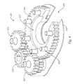
- FIG. 6discloses a perspective view of various internal components of the example open-faced rod-spinning device of FIG. 3 in accordance with an implementation of the present disclosure
- FIG. 7discloses a schematic top view of various internal components of the example open-faced rod-spinning device of FIG. 3 in accordance with an implementation of the present disclosure
- FIG. 8discloses a schematic view of an example system of magnets and a mounting plate
- FIG. 9discloses an exploded view of elements of the example open-faced rod-spinning device of FIG. 3 in accordance with an implementation of the present disclosure
- FIG. 10discloses an additional example carriage assembly of an open-faced rod-spinning device in accordance with an implementation of the present disclosure
- FIG. 11discloses an additional example open-faced rod-spinning device in accordance with an implementation of the present disclosure
- FIG. 12discloses an exploded view of a further example open-faced rod-spinning device in accordance with an implementation of the present disclosure
- FIG. 13discloses an example drive pin in accordance with an implementation of the present disclosure
- FIG. 14discloses various components of the example open-faced rod-spinning device of FIG. 12 in accordance with an implementation of the present disclosure.
- FIG. 15discloses a yet further example open-faced rod-spinning device in accordance with an implementation of the present disclosure.
- the present disclosureincludes systems, methods, and apparatuses configured for making and/or breaking joints between drill rods.
- the present disclosureincludes an open-faced drill rod-spinning device as well as corresponding systems and methods.
- the open-faced rod-spinning devicesmay allow for the selective engagement and disengagement of a drill string when desired to make or break a drill string joint.
- the open face of the rod-spinning deviceallows it to be stored in a disengaged position and then selectively brought forward to engage the drill string when necessary and then retracted when not needed.
- the process of making and breaking joints, as well as the process adding drill rods to or removing drill rods from a drill stringmay be quicker, easier, safer, and more efficient.
- FIG. 1illustrates a perspective view of an example drill rig 100 in accordance with an implementation of the present disclosure.
- the drill rig 100may include a base structure 105 which supports a drill mast 110 .
- the base structure 105may be mobilized in order to facilitate transportation of the drill rig 100 .
- the base structure 105may be coupled to a plurality of axles and wheels or a plurality of tracks in order to facilitate mobilization of the drill rig 100 .
- the drill mast 110is in a substantially horizontal position. However, once the drill rig 100 is positioned to begin the drilling process, the drill rig 100 may raise the drill mast 110 to any desired angle for the bore hole to be drilled. In one example embodiment, the angles at which the drill mast 110 may be positioned may include a range from about directly vertical or 0° to about a 45° angle.
- a rod-spinning device 200may be coupled directly to the drill mast 110 , may be coupled directly to the base structure 105 of the drill rig 100 , or may be coupled to a rod-handling device associated with the drill rig 100 or drill mast 110 . In a further embodiment, the rod-spinning device 200 may be used during the drilling process to selectively engage and disengage a drill string in order to make and/or break drill rod joints.
- FIG. 2illustrates an elevation view of the example drill mast 110 of FIG. 1 , including a rod-spinning device 200 associated therewith in accordance with an implementation of the present disclosure.
- the drill mast 110includes a support structure 115 which may support various components associated with the drill mast 110 , including a drill head 120 , the rod-spinning device 200 , and a clamping device 130 .
- the support structure 115may include various framing elements configured to give support to and/or guide drilling components during the drilling process.
- the support structure 115 of the drill mast 110may be configured to extend and retract between a first length and a second length greater than the first length.
- the support structure 115may be configured to move to a lower first length to facilitate transportation of the drill mast 110 and then move to a second length when in position to drill in order to extend the usable length of the drill mast 110 , thereby increasing the capability of handling longer drill rods during the drilling process.
- the second lengthmay be equal to or greater than twice the first length.
- the support structure 115may be coupled with and support a drill head 120 .
- the support structure 115may support the drill head 120 as the drill head 120 translates between an upper end 115 a and a lower end 115 b of the support structure 115 .
- FIG. 2illustrates the drill mast 110 with the drill head 120 located nearer the lower end 115 b of the support structure 115 .
- the drill head 120may be operatively associated with a drill string including any number of drill rods.
- the drill head 120may include mating features configured to engage corresponding mating features in the head or upper end of a drill rod.
- the drill head 120may include male features, such as external threads while a head or box end of the drill rod may include female features, such as internal threads configured to couple with the external threads of the drill head 120 . Accordingly, in at least one example, a box end of a drill rod may be rotated into engagement with the drill head 120 .
- a bit or pin end of the drill rodmay include male features, such as external threads, such that multiple drill rods may be coupled together to form a drill string.
- a drill bitmay be operatively associated with a lower or pin end of the drill string.
- the drill head 120applies forces to the drill string, which are at least partially transmitted to the drill bit to cause the drill bit and drill string to advance through a substrate.
- the forces applied to the drill stringmay include, without limitation, rotary, axial, percussive, and/or vibratory forces as well as any combination of forces.
- the following exampleswill be discussed in the context of a drill head that is configured to apply rotary and axial forces to the drill string and thence the drill bit.
- the rotary forcesmay be described herein as rotation in a clock-wise or first direction.
- the drill mast 110 and/or drill head 120may also include machinery and/or devices for translating the drill head 120 relative to the support structure 115 from the upper end 115 a to a lower end 115 b of the support structure 115 and vice versa.
- the drill mast 110 or drill head 120may include a chain drive, belt drive, or screw drive for translating the drill head 120 along the support structure 115 .
- the drill head 120may advance as the drill bit and drill string penetrate the substrate.
- FIG. 2further illustrates the rod-spinning device 200 coupled to the drill mast 110 above the clamping device 130 , and below the drill head 120 .
- the rod-spinning device 200may include an open face configured to selectively engage a drill rod or drill string.
- the open facemay face away from the drill mast 110 .
- the rod-spinning device 200may be located at any of a number of positions with its open face facing toward or away from the drill mast 110 .
- the rod-spinning device 200may be rotatably coupled to the side of the drill mast 100 and configured to rotate into an engaged position.
- the rod-spinning device 200may be independent of the drill mast 110 and may be moved into engagement when desired and moved out of engagement when not being used.
- the drill mast 110may include a clamping device 130 , such as a foot clamp, operatively associated with the support structure 115 .
- a clamping device 130such as a foot clamp
- both the clamping device 130 and the rod-spinning device 200may be disengaged from the drill string.
- the drill stringmay be clampingly retained to the lower end 115 b of the support structure 115 by the clamping device 130 and the drill head 120 may be reversed to break the joint between the drill head 120 and the clamped drill string.
- the clamping device 130may apply sufficient force to minimize rotation of the drill string as the drill head 120 is rotated in a counter-clockwise or second direction, the second direction being opposite the first direction.
- the drill head 120may be raised to the upper end 115 a of the support structure 115 and a new length of drill pipe may be loaded into the drill mast 110 .
- the drill head 120may then be lowered into proximity with the box end of the new length of drill pipe and rotated to engage the drill pipe.
- the drill head 120may then lower slowly until the pin end of the new length of drill pipe engages the box end of the drill string being clamped by the clamping device 130 .
- the rod-spinning device 200may be brought forward to engage and rotate the new length of drill pipe in order to make the joints between the new length of drill pipe and the drill string and/or between the new length of drill pipe and the drill head 120 .
- the rod-spinning device 200may apply a specified torque to the new length of drill pipe to achieve a specified torque in the joints with the drill head and/or drill string.
- the rod-spinning device 200may be horizontally extended on a plane perpendicular to the support structure 115 to engage the new length of drill pipe in a position which is just above the joint to be made between the new drill pipe and the drill string. After the joint is made, the rod-spinning device 200 may be refracted to a disengaged position.
- the rod-spinning device 200may be rotated from a vertical, disengaged position to a horizontal, engaged position. Once a joint is made or broken as desired, the rod-spinning device 200 may then rotate from the horizontal, engaged position to a vertical, disengaged position.
- the rod-spinning device 200may be independent of the drill mast 110 and may be configured to be rolled, moved, and/or rotated into place to engage a drill rod and rolled or moved away to disengage the drill rod.
- the example rod-spinning device 200may include a casing 202 and casing cover 203 configured to house the internal components of the example rod-spinning device 200 .
- the casing 202may include an open face 208 (or channel) configured to receive/engage an elongated member such as a drill rod.
- the casing cover 203may include a single plate-like piece, or, in a further embodiment, may include a plurality of pieces forming the casing cover 203 .
- the casing cover 203may be split down the middle to facilitate maintenance of the internal components of the rod-spinning device 200 without having to remove the entire casing cover 203 or remove other components, such as the motor 204 .
- FIG. 3also illustrates a motor 204 coupled to the casing 202 which may be configured for driving the internal components of the rod-spinning device 200 .
- the motor 204may be a hydraulic motor.
- the motor 204may be an electric motor, a combustion motor, or other similar motors.
- the example motor 204 of FIG. 3is shown mounted on the top of the rod-spinning device 200 , in further embodiments, the motor 204 may be mounted at any location of the rod-spinning device 200 as desired.
- the casing 202 of the rod-spinning device 200may house various internal components, including a carriage assembly 210 and a drive gear 226 .
- the carriage assembly 210 and drive gear 226may also each include an open face configured for receiving a drill rod.
- the motor 204may be actuated until the open face of the carriage assembly 210 aligns with the open face 208 of the casing 202 .
- the open face of the drive gear 226may not be aligned with the open face of the carriage assembly 210 during rotation, it may be necessary to reverse the motor 204 slightly such that the open face of the drive gear 226 also aligns with the open face 208 of the casing 202 .
- This positionas illustrated in FIG. 3 , may be referred to herein as the parked position.
- the rod-spinning device 200may be brought forward to a working position, wherein the rod-spinning device 200 receives and engages a drill rod.
- the motor 204may selectively operate the drive gear 226 and carriage assembly 210 to engage and rotate the drill rod in a clockwise or counter-clockwise direction.
- the example gear system 220may include a pinion gear 222 , two idler gears 224 , a drive gear 226 , and a plurality of drive pins 228 coupled to the drive gear 226 .
- the drive gear 226may include an open face and a hollow center such that the drive gear 226 may releasably engage and rotate about a drill rod.
- the motori.e., 204 , FIG. 3
- the motormay be configured to drive the drive gear 226 according to a drive chain in which the motor 204 rotates the pinion gear 222 , which then engages and rotates the pair of idler gears 224 , which in turn engage and rotate the drive gear 226 .
- the use of multiple idler gears 224may facilitate rotation of the drive gear 226 despite the open face of the drive gear 226 .
- the multiple idler gears 224may be positioned such that at least one idler gear 224 engages the teeth of the drive gear 226 at all times as the drive gear 226 rotates despite the gap in the drive gear 226 created by the drive gear's open face.
- the drive gear 226may include or be coupled to drive pins 228 configured to engage and rotate the carriage assembly (i.e., 210 , FIG. 5 ).
- the drive gear 226may also include a recess 227 in which the carriage assembly (i.e., 210 , FIG. 3 ) may be at least partially positioned.
- Torque generated by the rod-spinning device 200may be a function of the torque output of the motor 204 and the gear reduction between the pinion gear 222 and the drive gear 226 .
- the amount of torque applied by the rod-spinning device 200 to a drill rodmay be controlled by adjusting the torque output of the motor 204 . Accordingly, a specified desired torque may be achieved in making drill rod joints.
- FIG. 5illustrates an exploded view of a carriage assembly 210 and drive gear 226 of an example rod-spinning device 200 of FIG. 1 in accordance with an implementation of the present disclosure.
- the carriage assembly 210may include a top plate 212 and a bottom plate 214 that define a space therebetween.
- the top plate 212 and bottom plate 214may be coupled together by a plurality of pins 216 , 215 , including pivot pins 216 and/or spacer pins 215 .
- the pivot pins 216may be configured to act as axles for a plurality of gripping lobes 218 .
- each pivot pin 216may couple at one end to the top plate 212 , pass through a corresponding gripping lobe 218 , and then couple at the opposite end to the bottom plate 214 .
- the spacer pins 215may ensure proper spacing of the top plate 212 and bottom plate 214 to allow the gripping lobes 218 to rotate freely about the pivot pins 216 .
- the drive gear 226may include a recess 227 or cavity configured for receiving the bottom plate 214 of the carriage assembly 210 .
- the carriage assembly 210may also be configured to rotate within the recess 227 and relative to the drive gear 226 . Accordingly, as the drive gear 226 rotates relative to the carriage assembly 210 , the drive pins 228 may engage the gripping lobes 218 and rotate the gripping lobes 218 about the pivot pins 216 . Rotation of the gripping lobes 218 may move the gripping surface 219 and/or gripping elements 219 a inward toward a drill rod. Once the gripping lobes 218 have engaged the outside diameter of the drill rod, the drive gear 226 , carriage assembly 210 , and engaged drill rod may rotate together.
- a carriage assembly bearing 230may also be included and placed in the recess 227 between the drive gear 226 and the bottom plate 214 of the carriage assembly 210 .
- the carriage assembly bearing 230may be configured to facilitate the rotation of the carriage assembly 210 .
- the carriage assembly bearing 230may be manufactured using any material that will allow the bottom plate 214 of the carriage assembly 210 to rotate within the recess 227 relative to the drive gear 226 .
- the carriage assembly bearing 230is manufactured using a polymer, such as polyethylene.
- the rod-spinning device 200may include a friction element (i.e., 232 , FIG. 6 ) configured to apply a sufficient frictional force to the carriage assembly 210 to facilitate relative movement between the drive gear 226 and carriage assembly 210 as the drive gear 226 rotates, as discussed in more detail below.
- the gripping lobes 218may include a head end 218 a , a flared tail end 218 b , and a narrow waist 218 c .
- the head end 218 amay define a gripping surface 219 configured to engage the outside surface of a drill rod.
- the head end 218 amay further include gripping elements 219 a along the gripping surface 219 , wherein the gripping elements 219 a are configured for providing grip to the outside diameter of a drill rod.
- the gripping elements 219 amay include tungsten carbide inserts.
- the gripping elements 219 amay include any teeth or pyramidal points configured to grip the outside surface of a drill rod.
- the head end 218 a of the gripping lobes 218may be eccentrically shaped such that rotating the gripping lobes 218 about the pivot pins 216 produces a cam effect wherein the gripping surface 219 of the gripping lobe 218 extends forward to engage a drill rod.
- the waist 218 c and flared tail end 218 bmay be configured to be engaged by the drive pins 228 to rotate the gripping lobes 218 about the pivot pins 216 .
- the waist 218 c and flared tail end 218 bmay define one or more indentations 218 d along the sides of the gripping lobe 218 configured for receiving a drive pin 228 .
- a drive pin 228may engage the gripping lobe 218 to rotate the gripping lobe 218 about the pivot pin 216 into engagement with a drill rod.
- the entire carriage assembly 210rotates once the gripping lobes 218 engage the outside surface of a drill rod, thereby resisting any further rotation by the gripping lobes 218 about the pivot pins 216 .
- the indentations 218 dmay be located on each side of the gripping lobe 218 in order to receive drive pins 228 from either side. As a result, drive pins 228 may engage and rotate the gripping lobe 218 in either a clockwise or counter-clockwise direction. In one implementation, the indentations 218 d may be either curved and/or angular shape.
- each of the gripping lobes 218may be symmetrically shaped about a centered, vertical plane extending through the centers of each of the tail end 218 b and head end 218 a .
- This symmetric configurationmay allow the gripping lobes 218 to operate similarly whether engaged by a drive pin 228 rotating in a clockwise or counter-clockwise direction. Accordingly, the gripping lobes 218 may engage and rotate a drill rod in different rotational directions to selectively make and/or break drill rod joints.
- FIG. 5further illustrates a plurality of drive pins 228 coupled to the drive gear 226 .
- the drive gear 226is configured to include two drive pins 228 for every gripping lobe 218 of the carriage assembly 210 such that one drive pin 228 may be located on each side of the gripping lobes 218 .
- the drive pins 228may be further configured to engage and rotate the gripping lobes 218 .
- the rod-spinning devicemay include more or less drive pins 228 and more or less gripping lobes 218 than shown in FIG. 5 .
- FIG. 6illustrates a perspective view of the internal components of the rod-spinning device 200 of FIGS. 1-5 wherein the carriage assembly 210 is assembled into the rod-spinning device 200 atop the drive gear 226 .
- the carriage assembly 210may be positioned on top of the drive gear 226 such that the bottom plate 214 of the carriage assembly 210 is positioned at least partially within the recess 227 of the drive gear 226 .
- the drive pins 228may be configured to be located on opposite sides of the gripping lobes 218 .
- FIG. 6further illustrates a friction element 232 located on top of the carriage assembly 210 .
- the friction element 232may be coupled to the underside of a casing cover (i.e., 203 , FIG. 3 ) and configured to apply a frictional force to the top plate 212 of the carriage assembly 210 . Accordingly, when the motor 204 is actuated and the drive gear 226 rotates via the drive chain described above, the friction element 232 may apply a sufficient frictional force to the top plate 212 of the carriage assembly 210 to maintain the carriage assembly 210 stationary as the drive gear 226 rotates.
- the friction element 232applies a frictional force greater than the frictional force between the bottom plate 214 and the bearing 230 or between the bearing 230 and the drive gear 226 .
- the drive gear 226continues to rotate relative to the carriage assembly 210 until the drive pins 228 come into contact with and engage the gripping lobes 218 , causing the gripping lobes 218 to rotate about the pivot pins (i.e., 216 , FIG. 5 ).
- the gripping lobes 218may rotate about the pivot pins (i.e., 216 , FIG. 5 ) until the gripping surface 219 and/or gripping elements (i.e., 219 a , FIG.
- the frictional force of the friction element 232may be selectively applied and released as desired. For example, an operator may selectively activate the friction element 232 to apply a frictional force to the carriage assembly 210 and then deactivate the friction element 232 to release the frictional force from carriage assembly 210 .
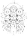
- FIG. 7illustrates a schematic top view of some components of the example rod-spinning device 200 of FIG. 1 engaging a drill rod 300 .
- FIG. 7illustrates the drive gear 226 , drive pins 228 , gripping lobes 218 , bottom plate 214 , gripping elements 219 , pinion gear 222 , and idler gears 224 .
- FIG. 7further illustrates the centerline 234 of the drill rod 300 engaged by the rod-spinning device 200 .
- actuation of the motori.e., 204 , FIG. 3
- the carriage assembly 210may remain stationary as the drive gear 226 rotates until the drive pins 228 engage the gripping lobes 218 .
- the gripping lobes 218may rotate about the pivot pins 216 while the carriage assembly 210 remains otherwise stationary, causing the gripping surfaces 219 of the gripping lobes 218 to move towards the centerline 234 and engage the drill rod 300 .
- the friction from the friction element 232may be overcome and the drive gear 226 , carriage assembly 210 , and drill rod 300 rotate together to make or break a joint in a drill string.
- the torque applied to the drill rod 300may be controlled and configured to achieve a desired torque, such as a manufacturer-specified torque. In one embodiment, the manufacturer-specified torque may vary depending on the size of the drill rod 300 .
- the rod-spinning device 200may be configured to operate with various drill rod sizes. In one example embodiment, the rod-spinning device 200 may be configured, including configuring the size of the gripping lobes 218 and the open face 208 , to engage drill rods as small B-sized rods and as large as P-sized rods.
- the gripping lobes 218may include a mechanism for maintaining a desired alignment of the gripping lobes 218 .
- a first magnet 217may be placed near an upper surface of the gripping lobe 218 proximate the tail end 218 b or waist 218 c .
- a second magnet(not shown) may be placed near a bottom surface of the top plate (i.e., 212 , FIG.
- one or more additional magnets with the same polarity as the first magnet 217may be configured to repel the first magnet 217 away from undesirable alignments and towards a desired alignment.
- a mounting plate 240may be coupled to the top plate 214 of the carriage assembly 210 .
- a plurality of magnets 242 , 244 , 246may be coupled to the mounting plate 240 and configured to align the gripping lobe 218 .
- the mounting plate 240may include a second magnet 242 and a third magnet 244 configured with the same polarity as the first magnet 217 coupled to the gripping lobe 218 .
- the second magnet 242 and third magnet 244may repel the first magnet 217 from an unaligned position 248 towards a properly aligned position 249 .
- the gripping lobe 218may also move, such as by rotating, into a desired alignment.
- the mounting plate 240may include a fourth magnet 246 with opposite polarity as the first magnet 217 coupled to the gripping lobe 218 and configured to attract the first magnet 217 to the aligned position 249 , thereby aligning the gripping lobe 218 .
- the force of the driving pins 228may overcome the magnetic forces created by the magnets 217 , 242 , 244 , 246 and displaces the gripping lobes 218 from their magnetized alignment.
- the magnetic forcemay return the gripping lobes 218 to their magnetized alignment as shown in FIG. 7 so as not to obstruct the engagement and/or release of drill rods by the rod-spinning device 200 .
- each springmay be coupled at one end to a portion of the gripping lobe 218 and coupled at the other end to another portion of the carriage assembly.
- the springsmay be configured to return the gripping lobe 218 to a desired alignment when disengaged by the driving pins 228 . Accordingly, when the rod-spinning device 200 is in the parked position (shown in FIG. 7 ), the gripping lobes 218 may be aligned so as to easily receive or release the drill rod 300 .
- FIG. 9illustrates an exploded view of an example rod-spinning device 200 of the present disclosure.
- the rod-spinning device 200may include a casing 202 configured to house and allow rotation of a pinion gear 222 , idler gears 224 , and drive gear 226 .
- FIG. 9further illustrates the use of gear bearings 250 a , 250 b in conjunction with the pinion gear 222 , idler gears 224 , and drive gear 226 in order to facilitate rotational movement of the gears 222 , 224 , 226 .
- drive pins 228may be coupled to the drive gear 226 and configured to interface with gripping lobes 218 of a carriage assembly 210 .
- FIG. 9illustrates an exploded view of an example rod-spinning device 200 of the present disclosure.
- the rod-spinning device 200may include a casing 202 configured to house and allow rotation of a pinion gear 222 , idler gears 224 , and drive gear 226
- FIG. 9further illustrates the use of a carriage assembly bearing 230 at the point where the carriage assembly 210 interfaces with the drive gear 226 to facilitate independent rotational movement of the drive gear 226 relative to the carriage assembly 210 .
- a friction element 232may be coupled to the casing cover 203 .
- the friction element 232may be configured to apply a frictional force to the carriage assembly 210 to restrict rotational movement of the carriage assembly 210 with respect to the drive gear 226 as discussed in more detail above.
- the casing cover 203may be fastened to the casing 202 to contain the internal components of the rod-spinning device 200 .
- the illustrated rod-spinning devicefurther includes a motor 204 in mechanical communication with the pinion gear 222 and coupled to the casing 202 such that actuation of the motor 204 rotates the pinion gear 222 , which in turn rotates the idler gears 224 and drive gear 226 .
- rotation of the gears 224 , 226 and pinion gear 222may be facilitated by the gear bearings 250 a , 250 b.
- FIG. 10illustrates a further embodiment of an example carriage assembly 210 ′ in accordance with an additional implementation of the present disclosure.
- the example carriage assembly 210 ′ of this configurationmay be functionally similar to the example carriage assembly 210 previously described above and shown in FIGS. 1-9 in most respects, wherein certain features will not be described in relation to this configuration wherein those components may function in the manner as described above and are hereby incorporated into this additional configuration described below.
- Like structures and/or componentsmay be given like reference numerals.
- the carriage assembly 210 ′may have a flared open face 208 ′ have a flared opening to facilitate engagement of a drill rod.
- the top plate 212 ′ and bottom plate 214 ′may each include an open face with flared edges 212 a ′, 214 a ′.
- the flared edges 212 a ′, 214 a ′may provide a wider dimension near the mouths of the openings in order to more easily receive a drill rod into the carriage assembly 210 ′.
- the flared edges 212 a ′, 214 a ′may facilitate engaging a drill rod into a rod-spinning device (i.e., 200 , FIG.
- the flared opening 208 ′ of the carriage assembly 210 ′may reduce the rotational precision necessary to engage a drill rod without sacrificing the utility of the carriage assembly 210 ′.
- the top plate 212 ′ of the carriage assemblymay include one or more gaps 213 ′ for receiving a mounting plate (i.e., 240 , FIG. 8 ) configured to assist in maintaining the alignment of one or more gripping lobes (i.e., 218 , FIG. 5 ) as described in more detail above.
- a mounting platei.e., 240 , FIG. 8
- FIG. 11illustrates an additional example embodiment of a rod-spinning device 200 ′′ in accordance with the present disclosure.
- the example rod-spinning device 200 ′′ of this configurationmay be functionally similar to the rod-spinning device 200 previously described above and shown in FIGS. 1-7 and 9 in most respects, wherein certain features will not be described in relation to this configuration wherein those components may function in the manner as described above and are hereby incorporated into this additional configuration described below.
- Like structures and/or componentsmay be given like reference numerals.
- the rod-spinning device 200 ′′may include a collar 280 ′′ coupled to the casing 202 ′′. As illustrated, the open face 208 ′′ of the rod-spinning device 200 ′′ may extend to the collar 280 ′′ to facilitate engaging and/or releasing a drill rod.
- the collar 280 ′′may couple to the casing cover 203 ′′ on top of the rod-spinning device 200 ′′.
- the collar 280 ′′may couple to any location of the rod-spinning device 200 ′′.
- a plurality of collars 280 ′′may be used. For example, in one embodiment, one collar 280 ′′ may be positioned on top of the rod-spinning device 200 ′′ and one collar 280 ′′ may be positioned on bottom of the rod-spinning device 200 ′′.
- FIG. 12illustrates an exploded view of an additional example rod-spinning device 400 in accordance with an implementation of the present disclosure.
- the example rod-spinning device 400 of this configurationmay be functionally similar to the rod-spinning devices 200 , 200 ′′ previously described above and shown in FIGS. 1-7 , 9 , and 11 in most respects, wherein certain features will not be described in relation to this configuration wherein those components may function in the manner as described above and are hereby incorporated into this additional configuration described below.
- Like structures and/or componentsmay be given like reference numerals.
- the rod-spinning device 400may include a casing 402 and casing cover 403 that at least partially enclose one or more components of the rod-spinning device 400 .
- the casing 402 and casing cover 403may at least partially enclose one or more gear bearings 450 that facilitate the rotation of one or more pinion gears 422 , idler gears 424 , and/or drive gears 426 .
- the drive gear 426may be coupled to one or more drive pins 428 .
- the drive pins 428may be disposed within one or more recesses within the drive gear 426 .
- the drive pins 428may also be configured to drive one or more gripping lobes 418 of a carriage assembly 410 .
- the carriage assembly 410may include a top plate 412 and bottom plate 414 with the one or more gripping lobes 418 disposed therebetween.
- the carriage assembly 410may further include one or more pivot pins connecting the top plate 412 to the bottom plate 414 and about which the one or more gripping lobes 418 may rotate.
- the carriage assembly 410may be configured to rotate relative to the drive gear 426 .
- the carriage assembly 410may be disposed within a recess 427 in the drive gear 426 configured to allow rotation of the carriage assembly 410 relative to the drive gear 426 .
- a carriage assembly bearing 430may be positioned within the recess 427 between the carriage assembly 410 and drive gear 426 to facilitate the relative rotation of the carriage assembly 410 .
- the rod-spinning device 400may further include a braking mechanism 490 .
- the braking mechanism 490may include a braking disc 491 and one or more braking calipers 492 operatively associated with the braking disc 491 .
- the braking disc 491may be coupled to the top plate 412 of the carriage assembly 410 .
- the braking calipers 492may be fixed in place, and the braking disc 491 may be configured to rotate and/or otherwise move relative to the braking calipers 492 .
- the braking calipers 492may be connected to the casing 402 or casing cover 403 and the braking disc 491 may be connected to and rotate with the top plate 412 of the carriage assembly 410 .
- an operatormay activate the braking calipers 492 in order to prevent rotation of the braking disc 491 and carriage assembly 410 when it is desired to prevent the carriage assembly 410 from rotating.
- the operatormay selectively engage and disengage the braking calipers 492 in order to selectively hold and release the braking disc 491 and carriage assembly 410 .
- FIG. 13discloses various components of the example rod-spinning device 400 in more detail.
- FIG. 13discloses the assembled motor 404 , pinion gear 422 , idler gears 424 , drive gear 426 , drive pins 428 , carriage assembly 410 , and braking mechanism 490 in accordance with an example implementation of the present disclosure.
- the braking mechanism 490may be coupled to the carriage assembly 410 .
- the braking disc 491may be connected to the top plate 412 of the carriage assembly 410 .
- the braking calipers 492may be connected to a casing 402 or casing cover 403 or other component.
- the braking disc 491may be disposed at least partially within the braking calipers 492 , such that activation of the braking calipers 492 applies a pressure and/or frictional force on the braking disc 491 to prevent or resist movement by the braking disc 491 and carriage assembly 410 relative to the braking calipers 492 . Accordingly, activating the braking calipers 492 may at least partially prevent the braking disc 491 and carriage assembly 410 from rotating.
- the braking calipers 492 and braking disc 491may include any number of materials.
- the braking calipers 492 and braking discmay include metals, composites, plastics, other similar materials, and/or combinations of the same.
- the braking calipersmay be configured to be activated with any of a number of different instrumentalities.
- the operatormay active the braking calipers 492 using pneumatics, hydraulics, electricity, magnetic forces, mechanical forces, other similar instrumentalities, and/or combinations of the same.
- a manufacturermay connect the braking disc 491 to the carriage assembly 410 using any number of fastening techniques.
- the manufacturemay connect the braking disc 491 to the carriage assembly using bolts, welds, adhesives, other fasteners, and/or combinations of the same.
- the braking disc 491may be an integral part of the top plate 412 of the carriage assembly 410 .
- one or more drive pins 428may include a detent mechanism configured to resist movement between the carriage assembly 410 and drive gear 426 .
- the detent mechanismmay include a detent member that is configured to extend upwards from the top of a drive pin 428 and move longitudinally, back and forth relative to the drive pin 428 .
- the detent membermay also extend towards the bottom surface of the top plate 412 of the carriage assembly 410 .
- the top plate 412may further include one or more corresponding indentations or holes configured to at least partially receive the detent member.
- the detent mechanismmay be further configured to apply an upward force to the detent member so as to push the detent member into an indentation in the top plate 412 and resist relative movement between the drive pin 428 and top plate 412 of the carriage assembly 410 .
- FIG. 14discloses an example drive pin 428 including an example detent mechanism 495 .
- the drive pin 428has a pin portion 428 a and a base portion 428 b .
- the pin portion 428 amay be configured to engage, rotate, and/or drive a gripping lobe 418 .
- the base portion 428 bmay be configured to be disposed within a corresponding recess in a drive gear 426 .
- the drive pin 428may include a detent mechanism 495 .
- the detent mechanismmay include a detent member 496 movable relative to the drive pin 428 and extending upward from the pin portion 428 a .
- the shape, size, and configuration of the detent member 496may be configured to be received by a corresponding indentation or hole in the top plate 412 of the carriage assembly 410 .
- the detent member 496may have one end that is rounded in shape.
- the detent member 496may have any shape, size, and/or configuration desired for a particular application.
- the detent mechanism 495may be further configured to provide an upward force on the detent member 496 in order to move the detent member 496 in a longitudinal direction into an indentation of the top plate 412 to resist movement between the drive pin 428 and top plate 412 , and thereby resist movement between the drive gear 426 and carriage assembly 410 .
- the detent mechanism 495may include a spring 497 that applies a constant force to the detent member 496 .
- the drive pins 428 and/or indentations in the top plate 412may be positioned such that the indentations receive the detent members 496 when the openings of the drive gear 426 and carriage assembly 410 are in alignment.
- the detent mechanism 495may be configured to apply selective forces to the detent member 496 .
- the detent mechanism 495may be configured to apply selective hydraulic, mechanical, pneumatic, magnetic, electrical, and/or other forces to the detent member 496 .
- an operatormay selectively activate the force on the detent member 496 when she desires to resist movement between the drive gear 426 and the carriage assembly 410 and deactivate the force on the detent member 496 when she desires to allow relative movement between the drive gear 426 and carriage assembly 410 .
- the detent mechanism 495may be configured to retract the detent member 496 when relative movement between the drive gear 426 and carriage assembly 410 is desired.
- any number of the drive pins 428may include a detent mechanism 495 .
- as many as all of the drive pins 428 and as few as one drive pin 428may include a detent mechanism 495 .
- two drive pins 428may each include a detent mechanism 495 while the remaining drive pins 428 do not.
- an operatormay make or break a drill rod joint with the example rod-spinning device 400 .
- the rod-spinning device 400may begin in a first position in which the carriage assembly 410 and drive gear 426 are aligned with the open face 408 of the casing 402 in order to receive a drill rod.
- the operatormay activate the motor 404 to begin to rotate the drive gear 426 in the desired direction.
- the braking calipers 492may apply pressure to the braking disc 491 in order to maintain the carriage assembly 410 stationary as the drive gear 426 begins to rotate. In so doing, the torque applied to the drive gear 426 in conjunction with the friction applied by the braking mechanism 490 may overcome the resistance to relative movement between the carriage assembly 410 and drive gear 426 created by the detent mechanisms 495 of the drive pins 428 . The relative rotation of the drive gear 426 with respect to the carriage assembly 410 may cause the drive pins 428 to engage and rotate the gripping lobes 418 until they engage the drill rod.
- the braking calipers 492may deactivate as the drive gear 426 continues to rotate in order to allow the drive gear 426 , carriage assembly 410 , and drill rod to rotate together to make or break a joint in a drill rod string.
- the braking calipers 492may activate and apply pressure to the braking disc 491 to resist movement of the carriage assembly 410 and facilitate relative movement between the carriage assembly 410 and the drive gear 426 .
- the operatormay then reverse the motor 404 in order to reverse the direction of and rotate the drive gear 426 until the open face of the drive gear 426 aligns with the open face of the carriage assembly 410 .
- the detent member 496 of the detent mechanism 495may be received by the indentations in the top plate 412 of the carriage assembly 410 to thereby resist further relative movement between the drive gear 426 and the carriage assembly 410 .
- the braking calipers 492may deactivate to release the braking disc 491 to allow the carriage assembly 410 to rotate with the drive gear 426 .
- the operatormay further reverse the motor 404 in order to align the openings of the carriage assembly 410 and drive gear 426 with the open face 408 of the casing 402 in order to release the drill rod.
- the braking mechanism 490may further include a timing device that selectively activates and deactivates the braking calipers 492 .
- the braking mechanism 490may include a hydraulic timer that selectively activates and deactivates the braking calipers 492 when desired to resist movement of the braking disc 491 and carriage assembly 410 .
- the hydraulic timermay apply hydraulic pressure to and relieve hydraulic pressure from the braking calipers 492 at appropriate times during the process of making and breaking drill rod joints in order to ensure the proper relative rotation between the drive gear 426 and carriage assembly 410 .
- the timing devicesuch as a hydraulic timer, may automatically activate and deactivate at appropriate times during the process of making and breaking drill rod joints.
- the hydraulic timermay include a variable flow controller in series with an accumulator.
- An operatormay adjust the flow controller to control the time it takes for the accumulator to fill with fluid.
- pressuremay increase in the accumulator.
- An operatormay adjust flow through the flow controller and the pressure of the sequence valve in order to achieve the desired timing of activation and deactivation of the braking calipers 492 .
- the rod-spinning device 400may further include a switch that automatically deactivates or applies a brake to the motor 404 once the drive gear 426 and carriage assembly 410 are aligned with the open face 408 of the casing 402 .
- the rod-spinning device 400may include a directional control valve coupled to the motor 404 to stop rotation of the motor 404 once the drive gear 426 and carriage assembly 410 are aligned with the open face 408 of the casing 402 .
- FIG. 15illustrates a further example rod-spinning device 500 in accordance with an implementation of the present disclosure.
- the example rod-spinning device 500 of this configurationmay be functionally similar to the rod-spinning devices 200 , 200 ′′, 400 previously described above and shown in FIGS. 1-7 , 9 , and 11 - 14 in most respects, wherein certain features will not be described in relation to this configuration wherein those components may function in the manner as described above and are hereby incorporated into this additional configuration described below.
- Like structures and/or componentsmay be given like reference numerals.
- the rod-spinning device 500may include a gate 599 configured to at least partially close the open face 508 of the casing 502 and casing cover 503 .
- the gate 599may be configured to at least partially cover the open face 508 to protect the inner components of the rod-spinning device 500 and to prevent any unwanted objects from becoming caught in the rod-spinning device 500 .
- the gate 599may be coupled to a closing mechanism in order to selectively open and close the gate 599 as desired.
- the gate 599may be coupled to a hydraulic device configured to close and open the gate 599 as desired during the process of making or breaking a drill rod joint. Accordingly, the gate 599 may improve the integrity and safety of the rod-spinning device.
Landscapes
- Engineering & Computer Science (AREA)
- Geology (AREA)
- Life Sciences & Earth Sciences (AREA)
- Mining & Mineral Resources (AREA)
- Physics & Mathematics (AREA)
- Environmental & Geological Engineering (AREA)
- Fluid Mechanics (AREA)
- Mechanical Engineering (AREA)
- General Life Sciences & Earth Sciences (AREA)
- Geochemistry & Mineralogy (AREA)
- Earth Drilling (AREA)
- Re-Forming, After-Treatment, Cutting And Transporting Of Glass Products (AREA)
- Drilling And Boring (AREA)
Abstract
Description
Claims (12)
Priority Applications (1)
| Application Number | Priority Date | Filing Date | Title |
|---|---|---|---|
| US13/188,249US8291791B2 (en) | 2008-05-12 | 2011-07-21 | Open-faced rod spinning device |
Applications Claiming Priority (3)
| Application Number | Priority Date | Filing Date | Title |
|---|---|---|---|
| US5257708P | 2008-05-12 | 2008-05-12 | |
| US12/464,707US8006590B2 (en) | 2008-05-12 | 2009-05-12 | Open-faced rod spinner |
| US13/188,249US8291791B2 (en) | 2008-05-12 | 2011-07-21 | Open-faced rod spinning device |
Related Parent Applications (1)
| Application Number | Title | Priority Date | Filing Date |
|---|---|---|---|
| US12/464,707ContinuationUS8006590B2 (en) | 2008-05-12 | 2009-05-12 | Open-faced rod spinner |
Publications (2)
| Publication Number | Publication Date |
|---|---|
| US20110271797A1 US20110271797A1 (en) | 2011-11-10 |
| US8291791B2true US8291791B2 (en) | 2012-10-23 |
Family
ID=41265796
Family Applications (2)
| Application Number | Title | Priority Date | Filing Date |
|---|---|---|---|
| US12/464,707Expired - Fee RelatedUS8006590B2 (en) | 2008-05-12 | 2009-05-12 | Open-faced rod spinner |
| US13/188,249Expired - Fee RelatedUS8291791B2 (en) | 2008-05-12 | 2011-07-21 | Open-faced rod spinning device |
Family Applications Before (1)
| Application Number | Title | Priority Date | Filing Date |
|---|---|---|---|
| US12/464,707Expired - Fee RelatedUS8006590B2 (en) | 2008-05-12 | 2009-05-12 | Open-faced rod spinner |
Country Status (9)
| Country | Link |
|---|---|
| US (2) | US8006590B2 (en) |
| EP (1) | EP2274498A2 (en) |
| CN (1) | CN102007263A (en) |
| AU (1) | AU2009246461B2 (en) |
| BR (1) | BRPI0911039A2 (en) |
| CA (1) | CA2720969C (en) |
| NZ (1) | NZ588426A (en) |
| WO (1) | WO2009140281A2 (en) |
| ZA (1) | ZA201007056B (en) |
Cited By (46)
| Publication number | Priority date | Publication date | Assignee | Title |
|---|---|---|---|---|
| US20130025416A1 (en)* | 2011-07-28 | 2013-01-31 | Snap-On Incorporated | Box wrench with split gear body and interchangeable drive insert |
| US20140174261A1 (en)* | 2012-11-27 | 2014-06-26 | American Certification And Pull Testing, Llc | Power tong and backup tong apparatus |
| US20140345426A1 (en)* | 2011-09-29 | 2014-11-27 | National Oilwell Varco Norway As | Simultaneous Clamp and Torque Drive |
| US20150143960A1 (en)* | 2013-11-25 | 2015-05-28 | Honghua America, Llc | Power tong for turning pipe |
| US20170065365A1 (en)* | 2013-10-24 | 2017-03-09 | Auris Surgical Robotics, Inc. | Instrument Device Manipulator with Surgical Tool De-Articulation |
| US9593543B2 (en) | 2013-12-30 | 2017-03-14 | Bly Ip Inc. | Drill rod handling system for moving drill rods to and from an operative position |
| US20170367782A1 (en)* | 2015-09-09 | 2017-12-28 | Auris Surgical Robotics, Inc. | Instrument device manipulator with back-mounted tool attachment mechanism |
| US10213264B2 (en) | 2013-03-14 | 2019-02-26 | Auris Health, Inc. | Catheter tension sensing |
| US10219874B2 (en) | 2013-10-24 | 2019-03-05 | Auris Health, Inc. | Instrument device manipulator with tension sensing apparatus |
| US10398518B2 (en) | 2014-07-01 | 2019-09-03 | Auris Health, Inc. | Articulating flexible endoscopic tool with roll capabilities |
| US20190316428A1 (en)* | 2018-04-13 | 2019-10-17 | Forum Us, Inc. | Wrench assembly with eccentricity sensing circuit |
| US10454347B2 (en) | 2016-04-29 | 2019-10-22 | Auris Health, Inc. | Compact height torque sensing articulation axis assembly |
| US10470830B2 (en) | 2017-12-11 | 2019-11-12 | Auris Health, Inc. | Systems and methods for instrument based insertion architectures |
| US10478595B2 (en) | 2013-03-07 | 2019-11-19 | Auris Health, Inc. | Infinitely rotatable tool with finite rotating drive shafts |
| US10493239B2 (en) | 2013-03-14 | 2019-12-03 | Auris Health, Inc. | Torque-based catheter articulation |
| US10524867B2 (en) | 2013-03-15 | 2020-01-07 | Auris Health, Inc. | Active drive mechanism for simultaneous rotation and translation |
| US10543047B2 (en) | 2013-03-15 | 2020-01-28 | Auris Health, Inc. | Remote catheter manipulator |
| US10543048B2 (en) | 2016-12-28 | 2020-01-28 | Auris Health, Inc. | Flexible instrument insertion using an adaptive insertion force threshold |
| US10556092B2 (en) | 2013-03-14 | 2020-02-11 | Auris Health, Inc. | Active drives for robotic catheter manipulators |
| US10569052B2 (en) | 2014-05-15 | 2020-02-25 | Auris Health, Inc. | Anti-buckling mechanisms for catheters |
| US10612322B2 (en) | 2016-04-25 | 2020-04-07 | Usinage Marcotte Inc. | Rod handling system |
| US10682189B2 (en) | 2016-08-31 | 2020-06-16 | Auris Health, Inc. | Length conservative surgical instrument |
| US10687903B2 (en) | 2013-03-14 | 2020-06-23 | Auris Health, Inc. | Active drive for robotic catheter manipulators |
| US10695536B2 (en) | 2001-02-15 | 2020-06-30 | Auris Health, Inc. | Catheter driver system |
| US10792112B2 (en) | 2013-03-15 | 2020-10-06 | Auris Health, Inc. | Active drive mechanism with finite range of motion |
| US10808469B2 (en) | 2017-05-31 | 2020-10-20 | Forum Us, Inc. | Wrench assembly with floating torque bodies |
| US10820947B2 (en) | 2018-09-28 | 2020-11-03 | Auris Health, Inc. | Devices, systems, and methods for manually and robotically driving medical instruments |
| US10820954B2 (en) | 2018-06-27 | 2020-11-03 | Auris Health, Inc. | Alignment and attachment systems for medical instruments |
| US10820952B2 (en) | 2013-03-15 | 2020-11-03 | Auris Heath, Inc. | Rotational support for an elongate member |
| US10888386B2 (en) | 2018-01-17 | 2021-01-12 | Auris Health, Inc. | Surgical robotics systems with improved robotic arms |
| US20210010336A1 (en)* | 2017-08-11 | 2021-01-14 | Weatherford Technology Holdings, Llc | Electric tong with onboard hydraulic power unit |
| US11026758B2 (en) | 2017-06-28 | 2021-06-08 | Auris Health, Inc. | Medical robotics systems implementing axis constraints during actuation of one or more motorized joints |
| US11147637B2 (en) | 2012-05-25 | 2021-10-19 | Auris Health, Inc. | Low friction instrument driver interface for robotic systems |
| US11213363B2 (en) | 2013-03-14 | 2022-01-04 | Auris Health, Inc. | Catheter tension sensing |
| US11241559B2 (en) | 2016-08-29 | 2022-02-08 | Auris Health, Inc. | Active drive for guidewire manipulation |
| US11278703B2 (en) | 2014-04-21 | 2022-03-22 | Auris Health, Inc. | Devices, systems, and methods for controlling active drive systems |
| US11382650B2 (en) | 2015-10-30 | 2022-07-12 | Auris Health, Inc. | Object capture with a basket |
| US11439419B2 (en) | 2019-12-31 | 2022-09-13 | Auris Health, Inc. | Advanced basket drive mode |
| US11510736B2 (en) | 2017-12-14 | 2022-11-29 | Auris Health, Inc. | System and method for estimating instrument location |
| US11534249B2 (en) | 2015-10-30 | 2022-12-27 | Auris Health, Inc. | Process for percutaneous operations |
| US11571229B2 (en) | 2015-10-30 | 2023-02-07 | Auris Health, Inc. | Basket apparatus |
| US11638618B2 (en) | 2019-03-22 | 2023-05-02 | Auris Health, Inc. | Systems and methods for aligning inputs on medical instruments |
| US11737845B2 (en) | 2019-09-30 | 2023-08-29 | Auris Inc. | Medical instrument with a capstan |
| US11771309B2 (en) | 2016-12-28 | 2023-10-03 | Auris Health, Inc. | Detecting endolumenal buckling of flexible instruments |
| US11896330B2 (en) | 2019-08-15 | 2024-02-13 | Auris Health, Inc. | Robotic medical system having multiple medical instruments |
| US11950872B2 (en) | 2019-12-31 | 2024-04-09 | Auris Health, Inc. | Dynamic pulley system |
Families Citing this family (37)
| Publication number | Priority date | Publication date | Assignee | Title |
|---|---|---|---|---|
| US7997166B2 (en) | 2007-06-15 | 2011-08-16 | Longyear Tm, Inc. | Methods and apparatus for joint disassembly |
| US7997167B2 (en) | 2007-08-30 | 2011-08-16 | Longyear Tm, Inc. | Clamping and breaking device |
| US20110174545A1 (en) | 2010-01-15 | 2011-07-21 | Vermeer Manufacturing Company | Drilling machine and method |
| CA2706500C (en)* | 2010-06-07 | 2017-09-19 | Kurt R. Feigel, Jr. | Compact power tong |
| KR101395519B1 (en) | 2010-11-17 | 2014-05-14 | 주식회사 케이티 | Drilling machine |
| US8967278B2 (en)* | 2011-01-19 | 2015-03-03 | Nabors Canada | Collar assembly for breaking tubing hanger connections |
| GB201222502D0 (en) | 2012-12-13 | 2013-01-30 | Titan Torque Services Ltd | Apparatus and method for connecting components |
| CN103015922B (en)* | 2012-12-31 | 2015-04-29 | 湘潭大学 | Drill rod holding device for trenchless horizontal directional drilling machine |
| US9677352B2 (en)* | 2013-06-05 | 2017-06-13 | Frank's International, Llc | Chuck spider |
| CN103806854A (en)* | 2014-01-29 | 2014-05-21 | 上海久卓机电设备有限公司 | Iron roughneck |
| CA2875483C (en)* | 2014-02-04 | 2017-01-03 | Brandt Engineered Products Ltd. | Method of operating a rock bolting machine |
| CN103953303B (en)* | 2014-05-04 | 2016-06-15 | 江苏如通石油机械股份有限公司 | A kind of novel tube rod closed power tong |
| NO20141449A1 (en) | 2014-12-02 | 2016-06-03 | Robotic Drilling Systems As | Grabs with swivels |
| US20170088401A1 (en)* | 2015-09-24 | 2017-03-30 | Quality Rental Tools, Inc. | Method and apparatus for handling lift subs and other objects |
| US11898628B2 (en) | 2015-11-30 | 2024-02-13 | Victaulic Company | Cam grooving machine |
| AU2016362959B2 (en)* | 2015-11-30 | 2019-05-23 | Victaulic Company | Cam grooving machine |
| US10400525B2 (en)* | 2016-05-13 | 2019-09-03 | Dr Fabrication Inc. | Rod positioning device |
| US10088585B2 (en)* | 2016-12-12 | 2018-10-02 | Pgs Geophysical As | Method and system for coupling geophysical sensor cable sections |
| CN106522862B (en)* | 2017-01-05 | 2018-07-31 | 吴立中 | A kind of hydraulic tongs with torque control instrument |
| NO343124B1 (en)* | 2017-02-24 | 2018-11-12 | West Drilling Products As | The pipe handler assembly |
| US10525516B2 (en) | 2017-05-03 | 2020-01-07 | Victaulic Company | Cam grooving machine with cam stop surfaces |
| CA2970340A1 (en) | 2017-06-13 | 2018-12-13 | Universe Machine Corporation | Power tong |
| US9828814B1 (en) | 2017-07-12 | 2017-11-28 | U.S. Power Tong, L.L.C. | Power tongs with shaft retainers |
| US10087691B1 (en) | 2017-07-12 | 2018-10-02 | U.S. Power Tong, Llc | Power tongs |
| US9890600B1 (en) | 2017-07-12 | 2018-02-13 | U.S. Power Tong, Llc | Power tongs with supporting struts |
| US10960450B2 (en) | 2017-12-19 | 2021-03-30 | Victaulic Company | Pipe grooving device |
| CN110340836A (en)* | 2018-04-04 | 2019-10-18 | 徐元启 | Reinforced bar sleeve is threadedly coupled electric wrench |
| CN109138872B (en)* | 2018-10-18 | 2023-12-15 | 广西科技大学 | Novel automatic drilling rod feeding system |
| WO2021035024A1 (en) | 2019-08-21 | 2021-02-25 | Victaulic Company | Pipe grooving device having flared cup |
| US11572746B2 (en) | 2019-10-18 | 2023-02-07 | Weatherford Technology Holdings Llc | Rotary gripping apparatus for a power tong |
| CN110666745B (en)* | 2019-10-30 | 2021-04-13 | 萧县亿达信息科技有限公司 | Long-strip screw nut screwing device |
| US11629561B2 (en) | 2020-02-03 | 2023-04-18 | Weatherford Technology Holdings, LLC. | Brakes for a tong |
| US11759839B2 (en)* | 2020-09-24 | 2023-09-19 | Victaulic Company | Pipe grooving device |
| US20240410237A1 (en)* | 2023-06-12 | 2024-12-12 | Warrior Rig Technologies US LLC | Wrench assembly bumper plate systems |
| WO2025024513A1 (en)* | 2023-07-24 | 2025-01-30 | Boart Longyear Company | Drill rod and core tube handler device |
| CN118669067B (en)* | 2024-07-30 | 2025-09-05 | 建湖县恒泰石油机械有限公司 | A hydraulic power caliper with low-wear braking structure |
| CN120007104B (en)* | 2025-04-18 | 2025-07-08 | 山西路桥建设集团有限公司 | Bridge pile foundation drilling equipment |
Citations (70)
| Publication number | Priority date | Publication date | Assignee | Title |
|---|---|---|---|---|
| US430994A (en) | 1890-06-24 | Pipe-wrench | ||
| US621293A (en) | 1899-03-14 | George f | ||
| US712253A (en) | 1902-08-06 | 1902-10-28 | Joseph D Brown | Chain wrench. |
| US1416685A (en) | 1921-06-30 | 1922-05-23 | J H Williams & Company | Chain pipe wrench |
| US2633045A (en) | 1949-04-20 | 1953-03-31 | Benjamin L Lurie | Pipe wrench having arm with a recess therein and a pivotally mounted spring-biased pipe-engaging jaw in the recess |
| US2650070A (en) | 1950-04-08 | 1953-08-25 | Byron Jackson Co | Pipe gripping mechanism for power tongs |
| US2921489A (en) | 1957-03-18 | 1960-01-19 | Standard Oil Co | Chain-type pipe wrench |
| US2928301A (en) | 1957-07-18 | 1960-03-15 | Archie W Beeman | Power operated spinning devices for pipe |
| US2933961A (en) | 1957-10-28 | 1960-04-26 | Orville A Adams | Power operated pipe wrench |
| US2989880A (en) | 1958-07-03 | 1961-06-27 | Earl D Hesser | Power tongs |
| US3196717A (en)* | 1963-07-29 | 1965-07-27 | Billy K Sheppard | Pipe gripping mechanism for casing tongs |
| US3880024A (en) | 1973-07-30 | 1975-04-29 | Tokai Tekkosha Kk | Portable power wrench |
| US3892140A (en) | 1973-05-07 | 1975-07-01 | Weatherford Oil Tool | Rotary drive apparatus |
| US4060014A (en)* | 1976-04-29 | 1977-11-29 | Joy Manufacturing Company | Power tong |
| US4079640A (en) | 1976-10-18 | 1978-03-21 | Golden R L | Pipe make up device |
| US4212212A (en) | 1978-10-06 | 1980-07-15 | Weatherford/Lamb, Inc. | Rotary drive apparatus |
| US4221269A (en) | 1978-12-08 | 1980-09-09 | Hudson Ray E | Pipe spinner |
| US4324157A (en) | 1980-01-28 | 1982-04-13 | Soutsos Michael D | Drill pipe clamp |
| US4485697A (en) | 1983-04-29 | 1984-12-04 | Foster Cathead Company | Kelly spinner |
| US4512216A (en) | 1984-01-20 | 1985-04-23 | Tommie Rogers | Pipe spinner |
| US4604922A (en) | 1984-09-17 | 1986-08-12 | Soutsos Michael D | Drill pipe turning device |
| JPS62156468A (en) | 1985-12-27 | 1987-07-11 | 元旦ビューティ工業株式会社 | roof eaves structure |
| US4683962A (en) | 1983-10-06 | 1987-08-04 | True Martin E | Spinner for use in connecting pipe joints |
| US4694712A (en) | 1985-09-26 | 1987-09-22 | Doss Hubert M | Well string section spinning tool |
| US4765401A (en) | 1986-08-21 | 1988-08-23 | Varco International, Inc. | Apparatus for handling well pipe |
| US4843924A (en) | 1987-09-10 | 1989-07-04 | Hawk Industries, Inc. | Compact high-torque apparatus and method for rotating pipe |
| US4869137A (en)* | 1987-04-10 | 1989-09-26 | Slator Damon T | Jaws for power tongs and bucking units |
| US4885963A (en) | 1988-02-26 | 1989-12-12 | Mcc Corporation | Oscillating drive apparatus for working tool and working apparatus using the same |
| US4895056A (en) | 1988-11-28 | 1990-01-23 | Weatherford U.S., Inc. | Tong and belt apparatus for a tong |
| JPH02194984A (en) | 1989-01-23 | 1990-08-01 | Seiko Epson Corp | ink roll |
| US5054550A (en) | 1990-05-24 | 1991-10-08 | W-N Apache Corporation | Centering spinning for down hole tubulars |
| US5060542A (en) | 1990-10-12 | 1991-10-29 | Hawk Industries, Inc. | Apparatus and method for making and breaking joints in drill pipe strings |
| US5092411A (en) | 1988-03-15 | 1992-03-03 | Rudolf Hausherr & Sohne Gmbh & Co. Kg | Drilling apparatus |
| US5207128A (en) | 1992-03-23 | 1993-05-04 | Weatherford-Petco, Inc. | Tong with floating jaws |
| US5320021A (en) | 1993-02-05 | 1994-06-14 | Heintz Farrell E | Universal chain wrench and tools |
| JPH0762968A (en) | 1993-08-31 | 1995-03-07 | Nippon Soil Kogyo Kk | Fitting/removing device for tube body |
| US5435213A (en) | 1992-07-08 | 1995-07-25 | Buck; David A. | Ring gear camming member |
| US5660087A (en) | 1995-08-08 | 1997-08-26 | Rae; Donald David | Drill pipe spinner |
| JP2652808B2 (en) | 1989-09-29 | 1997-09-10 | 鉱研工業株式会社 | Down the hole drill rig |
| JPH09250285A (en) | 1996-03-14 | 1997-09-22 | Koken Boring Mach Co Ltd | Drilling rod gripping device |
| DE29720465U1 (en) | 1997-11-19 | 1998-01-02 | Hütte & Co Bohrtechnik GmbH, 57462 Olpe | Device for clamping and breaking drill strings |
| WO1998026153A1 (en) | 1996-12-11 | 1998-06-18 | Universal Drilling Systems (Aust) Pty. Ltd. | Apparatus for connecting and disconnecting drill rods |
| US5845549A (en) | 1995-12-20 | 1998-12-08 | Frank's Casing Crew And Rental Tools, Inc. | Power tong gripping ring mechanism |
| US5868045A (en) | 1993-05-26 | 1999-02-09 | Hawk Industries, Inc. | Apparatus for making and breaking joints in drill pipe strings |
| WO1999006186A1 (en) | 1997-07-29 | 1999-02-11 | Universal Drilling Systems (Aust) Pty. Limited | Apparatus for disconnecting drill rods |
| US5931231A (en) | 1996-06-27 | 1999-08-03 | Bucyrus International, Inc. | Blast hole drill pipe gripping mechanism |
| WO1999055728A2 (en) | 1998-04-27 | 1999-11-04 | Hsc Research And Development Limited Partnership | Ese genes and proteins |
| US6050156A (en) | 1996-11-26 | 2000-04-18 | Buck; David A. | Braking mechanism for power tongs |
| US6070500A (en) | 1998-04-20 | 2000-06-06 | White Bear Energy Serives Ltd. | Rotatable die holder |
| US6082225A (en) | 1994-01-31 | 2000-07-04 | Canrig Drilling Technology, Ltd. | Power tong wrench |
| US6318199B1 (en) | 2000-01-18 | 2001-11-20 | David A. Buck | Load equalizing power tong gear train |
| DE20202396U1 (en) | 2002-02-15 | 2002-06-06 | Prime Drilling GmbH, 57482 Wenden | Clamping device for round material |
| US20020157823A1 (en) | 1999-11-26 | 2002-10-31 | Bernd-Georg Pietras | Wrenching tong |
| WO2003033858A1 (en) | 2001-10-15 | 2003-04-24 | Udr Kl Pty Ltd | Apparatus and method for reducing required torque |
| JP2003184471A (en) | 2001-12-20 | 2003-07-03 | Yamamoto Rock Machine Co Ltd | Drilling apparatus |
| US20030177870A1 (en) | 2000-07-06 | 2003-09-25 | Neves Billy W. | High torque power tong |
| US6634443B1 (en) | 1999-04-28 | 2003-10-21 | Boart Longyear Pty. Ltd. | Drill rod handling device |
| US20030221871A1 (en) | 2002-05-30 | 2003-12-04 | Gray Eot, Inc. | Drill pipe connecting and disconnecting apparatus |
| US20050072274A1 (en) | 2001-03-19 | 2005-04-07 | Hawk Industries, Inc., A California Corporation | Variable rack adjustment assembly for pipe spinning machines |
| US6910402B2 (en) | 2003-08-13 | 2005-06-28 | National-Oilwell, L. P. | Pipe spinner |
| US6971283B2 (en) | 2002-09-12 | 2005-12-06 | National-Oilwell, L.P. | Jaw insert for gripping a cylindrical member and method of manufacture |
| US7000502B2 (en) | 2003-09-05 | 2006-02-21 | National-Ollwell | Drillpipe spinner |
| US20060053977A1 (en) | 2004-09-16 | 2006-03-16 | Hawkins Samuel P Iii | Apparatus and method for assembling and disassembling downhole components in a horizontal mode |
| US20060054331A1 (en) | 2004-09-16 | 2006-03-16 | Hawkins Samuel P Iii | Apparatus and method for making up and breaking out threaded connections of drill bits and bottomhole components |
| US20060243490A1 (en) | 2005-04-28 | 2006-11-02 | Astec Industries, Inc. | Apparatus and method for modified horizontal directional drilling assembly |
| US20070017703A1 (en) | 2005-07-19 | 2007-01-25 | National-Oilwell, L.P. | Single joint drilling system with inclined pipe handling system |
| US7188547B1 (en) | 2005-12-23 | 2007-03-13 | Varco I/P, Inc. | Tubular connect/disconnect apparatus |
| US7191686B1 (en) | 2006-02-01 | 2007-03-20 | Frank's Casing Crew & Rental Tools, Inc. | Method and apparatus for connecting and disconnecting threaded tubulars |
| EP1644608B1 (en) | 2003-06-27 | 2007-11-14 | The Charles Machine Works Inc | Coupling for dual member pipe |
| US20100083796A1 (en) | 2008-10-02 | 2010-04-08 | Nelson Robert M | Methods and apparatus for make up and break out of tubular connections |
Family Cites Families (4)
| Publication number | Priority date | Publication date | Assignee | Title |
|---|---|---|---|---|
| US5029411A (en)* | 1990-04-27 | 1991-07-09 | Keenan F Edward | Flea collecting apparatus |
| CN1156642C (en)* | 2001-02-03 | 2004-07-07 | 傅永森 | Fasten mechanism for planetary jew type open power wrench |
| CN200975217Y (en)* | 2006-11-09 | 2007-11-14 | 北京东方泰晟基础机械技术有限公司 | Canula drilling machine |
| US7997167B2 (en) | 2007-08-30 | 2011-08-16 | Longyear Tm, Inc. | Clamping and breaking device |
- 2009
- 2009-05-12CNCN2009801129407Apatent/CN102007263A/enactivePending
- 2009-05-12WOPCT/US2009/043633patent/WO2009140281A2/enactiveApplication Filing
- 2009-05-12EPEP09747365Apatent/EP2274498A2/ennot_activeWithdrawn
- 2009-05-12USUS12/464,707patent/US8006590B2/ennot_activeExpired - Fee Related
- 2009-05-12NZNZ588426Apatent/NZ588426A/ennot_activeIP Right Cessation
- 2009-05-12BRBRPI0911039Apatent/BRPI0911039A2/ennot_activeIP Right Cessation
- 2009-05-12AUAU2009246461Apatent/AU2009246461B2/ennot_activeCeased
- 2009-05-12CACA2720969Apatent/CA2720969C/ennot_activeExpired - Fee Related
- 2010
- 2010-10-04ZAZA2010/07056Apatent/ZA201007056B/enunknown
- 2011
- 2011-07-21USUS13/188,249patent/US8291791B2/ennot_activeExpired - Fee Related
Patent Citations (72)
| Publication number | Priority date | Publication date | Assignee | Title |
|---|---|---|---|---|
| US430994A (en) | 1890-06-24 | Pipe-wrench | ||
| US621293A (en) | 1899-03-14 | George f | ||
| US712253A (en) | 1902-08-06 | 1902-10-28 | Joseph D Brown | Chain wrench. |
| US1416685A (en) | 1921-06-30 | 1922-05-23 | J H Williams & Company | Chain pipe wrench |
| US2633045A (en) | 1949-04-20 | 1953-03-31 | Benjamin L Lurie | Pipe wrench having arm with a recess therein and a pivotally mounted spring-biased pipe-engaging jaw in the recess |
| US2650070A (en) | 1950-04-08 | 1953-08-25 | Byron Jackson Co | Pipe gripping mechanism for power tongs |
| US2921489A (en) | 1957-03-18 | 1960-01-19 | Standard Oil Co | Chain-type pipe wrench |
| US2928301A (en) | 1957-07-18 | 1960-03-15 | Archie W Beeman | Power operated spinning devices for pipe |
| US2933961A (en) | 1957-10-28 | 1960-04-26 | Orville A Adams | Power operated pipe wrench |
| US2989880A (en) | 1958-07-03 | 1961-06-27 | Earl D Hesser | Power tongs |
| US3196717A (en)* | 1963-07-29 | 1965-07-27 | Billy K Sheppard | Pipe gripping mechanism for casing tongs |
| US3892140A (en) | 1973-05-07 | 1975-07-01 | Weatherford Oil Tool | Rotary drive apparatus |
| US3880024A (en) | 1973-07-30 | 1975-04-29 | Tokai Tekkosha Kk | Portable power wrench |
| US4060014A (en)* | 1976-04-29 | 1977-11-29 | Joy Manufacturing Company | Power tong |
| US4079640A (en) | 1976-10-18 | 1978-03-21 | Golden R L | Pipe make up device |
| US4212212A (en) | 1978-10-06 | 1980-07-15 | Weatherford/Lamb, Inc. | Rotary drive apparatus |
| US4221269A (en) | 1978-12-08 | 1980-09-09 | Hudson Ray E | Pipe spinner |
| US4324157A (en) | 1980-01-28 | 1982-04-13 | Soutsos Michael D | Drill pipe clamp |
| US4485697A (en) | 1983-04-29 | 1984-12-04 | Foster Cathead Company | Kelly spinner |
| US4683962A (en) | 1983-10-06 | 1987-08-04 | True Martin E | Spinner for use in connecting pipe joints |
| US4512216A (en) | 1984-01-20 | 1985-04-23 | Tommie Rogers | Pipe spinner |
| US4604922A (en) | 1984-09-17 | 1986-08-12 | Soutsos Michael D | Drill pipe turning device |
| US4694712A (en) | 1985-09-26 | 1987-09-22 | Doss Hubert M | Well string section spinning tool |
| JPS62156468A (en) | 1985-12-27 | 1987-07-11 | 元旦ビューティ工業株式会社 | roof eaves structure |
| US4765401A (en) | 1986-08-21 | 1988-08-23 | Varco International, Inc. | Apparatus for handling well pipe |
| US4869137A (en)* | 1987-04-10 | 1989-09-26 | Slator Damon T | Jaws for power tongs and bucking units |
| US4843924A (en) | 1987-09-10 | 1989-07-04 | Hawk Industries, Inc. | Compact high-torque apparatus and method for rotating pipe |
| US4885963A (en) | 1988-02-26 | 1989-12-12 | Mcc Corporation | Oscillating drive apparatus for working tool and working apparatus using the same |
| US5092411A (en) | 1988-03-15 | 1992-03-03 | Rudolf Hausherr & Sohne Gmbh & Co. Kg | Drilling apparatus |
| US4895056A (en) | 1988-11-28 | 1990-01-23 | Weatherford U.S., Inc. | Tong and belt apparatus for a tong |
| JPH02194984A (en) | 1989-01-23 | 1990-08-01 | Seiko Epson Corp | ink roll |
| JP2652808B2 (en) | 1989-09-29 | 1997-09-10 | 鉱研工業株式会社 | Down the hole drill rig |
| US5054550A (en) | 1990-05-24 | 1991-10-08 | W-N Apache Corporation | Centering spinning for down hole tubulars |
| US5060542A (en) | 1990-10-12 | 1991-10-29 | Hawk Industries, Inc. | Apparatus and method for making and breaking joints in drill pipe strings |
| US5207128A (en) | 1992-03-23 | 1993-05-04 | Weatherford-Petco, Inc. | Tong with floating jaws |
| US5435213A (en) | 1992-07-08 | 1995-07-25 | Buck; David A. | Ring gear camming member |
| US5320021A (en) | 1993-02-05 | 1994-06-14 | Heintz Farrell E | Universal chain wrench and tools |
| US5868045A (en) | 1993-05-26 | 1999-02-09 | Hawk Industries, Inc. | Apparatus for making and breaking joints in drill pipe strings |
| JPH0762968A (en) | 1993-08-31 | 1995-03-07 | Nippon Soil Kogyo Kk | Fitting/removing device for tube body |
| US6082225A (en) | 1994-01-31 | 2000-07-04 | Canrig Drilling Technology, Ltd. | Power tong wrench |
| US5660087A (en) | 1995-08-08 | 1997-08-26 | Rae; Donald David | Drill pipe spinner |
| US5845549A (en) | 1995-12-20 | 1998-12-08 | Frank's Casing Crew And Rental Tools, Inc. | Power tong gripping ring mechanism |
| JPH09250285A (en) | 1996-03-14 | 1997-09-22 | Koken Boring Mach Co Ltd | Drilling rod gripping device |
| US5931231A (en) | 1996-06-27 | 1999-08-03 | Bucyrus International, Inc. | Blast hole drill pipe gripping mechanism |
| US6050156A (en) | 1996-11-26 | 2000-04-18 | Buck; David A. | Braking mechanism for power tongs |
| WO1998026153A1 (en) | 1996-12-11 | 1998-06-18 | Universal Drilling Systems (Aust) Pty. Ltd. | Apparatus for connecting and disconnecting drill rods |
| WO1999006186A1 (en) | 1997-07-29 | 1999-02-11 | Universal Drilling Systems (Aust) Pty. Limited | Apparatus for disconnecting drill rods |
| DE29720465U1 (en) | 1997-11-19 | 1998-01-02 | Hütte & Co Bohrtechnik GmbH, 57462 Olpe | Device for clamping and breaking drill strings |
| US6070500A (en) | 1998-04-20 | 2000-06-06 | White Bear Energy Serives Ltd. | Rotatable die holder |
| WO1999055728A2 (en) | 1998-04-27 | 1999-11-04 | Hsc Research And Development Limited Partnership | Ese genes and proteins |
| US6634443B1 (en) | 1999-04-28 | 2003-10-21 | Boart Longyear Pty. Ltd. | Drill rod handling device |
| US20060179980A1 (en) | 1999-11-26 | 2006-08-17 | Weatherford/Lamb, Inc. | Wrenching tong |
| US20020157823A1 (en) | 1999-11-26 | 2002-10-31 | Bernd-Georg Pietras | Wrenching tong |
| US6318199B1 (en) | 2000-01-18 | 2001-11-20 | David A. Buck | Load equalizing power tong gear train |
| US20030177870A1 (en) | 2000-07-06 | 2003-09-25 | Neves Billy W. | High torque power tong |
| US20050072274A1 (en) | 2001-03-19 | 2005-04-07 | Hawk Industries, Inc., A California Corporation | Variable rack adjustment assembly for pipe spinning machines |
| WO2003033858A1 (en) | 2001-10-15 | 2003-04-24 | Udr Kl Pty Ltd | Apparatus and method for reducing required torque |
| JP2003184471A (en) | 2001-12-20 | 2003-07-03 | Yamamoto Rock Machine Co Ltd | Drilling apparatus |
| DE20202396U1 (en) | 2002-02-15 | 2002-06-06 | Prime Drilling GmbH, 57482 Wenden | Clamping device for round material |
| US7117938B2 (en) | 2002-05-30 | 2006-10-10 | Gray Eot, Inc. | Drill pipe connecting and disconnecting apparatus |
| US20030221871A1 (en) | 2002-05-30 | 2003-12-04 | Gray Eot, Inc. | Drill pipe connecting and disconnecting apparatus |
| US6971283B2 (en) | 2002-09-12 | 2005-12-06 | National-Oilwell, L.P. | Jaw insert for gripping a cylindrical member and method of manufacture |
| EP1644608B1 (en) | 2003-06-27 | 2007-11-14 | The Charles Machine Works Inc | Coupling for dual member pipe |
| US6910402B2 (en) | 2003-08-13 | 2005-06-28 | National-Oilwell, L. P. | Pipe spinner |
| US7000502B2 (en) | 2003-09-05 | 2006-02-21 | National-Ollwell | Drillpipe spinner |
| US20060054331A1 (en) | 2004-09-16 | 2006-03-16 | Hawkins Samuel P Iii | Apparatus and method for making up and breaking out threaded connections of drill bits and bottomhole components |
| US20060053977A1 (en) | 2004-09-16 | 2006-03-16 | Hawkins Samuel P Iii | Apparatus and method for assembling and disassembling downhole components in a horizontal mode |
| US20060243490A1 (en) | 2005-04-28 | 2006-11-02 | Astec Industries, Inc. | Apparatus and method for modified horizontal directional drilling assembly |
| US20070017703A1 (en) | 2005-07-19 | 2007-01-25 | National-Oilwell, L.P. | Single joint drilling system with inclined pipe handling system |
| US7188547B1 (en) | 2005-12-23 | 2007-03-13 | Varco I/P, Inc. | Tubular connect/disconnect apparatus |
| US7191686B1 (en) | 2006-02-01 | 2007-03-20 | Frank's Casing Crew & Rental Tools, Inc. | Method and apparatus for connecting and disconnecting threaded tubulars |
| US20100083796A1 (en) | 2008-10-02 | 2010-04-08 | Nelson Robert M | Methods and apparatus for make up and break out of tubular connections |
Non-Patent Citations (24)
| Title |
|---|
| International Search Report and Written Opinion dated Dec. 1, 2009 as issued in International Application No. PCT/US2009/043633 filed May 12, 2009. |
| International Search Report and Written Opinion dated Jan. 21, 2009 from International Patent Application No. PCT/US2008/074499 filed Aug. 27, 2008 (7 pages). |
| International Search Report and Written Opinion dated Oct. 28, 2009 from International Patent Application No. PCT/US2009/043628 filed May 12, 2009 (8 pages). |
| International Search Report dated Dec. 23, 2008 from International Patent Application No. PCT/US2008/067007 filed Jun. 13, 2008 (10 pages). |
| Issue Notification dated Aug. 10, 2011 from U.S. Appl. No. 12/464,707, filed May 12, 2009 (1 page). |
| Issue Notification dated Jul. 27, 2011 from U.S. Appl. No. 12/138,297, filed Jun. 12, 2008 (1 page). |
| Issue Notification dated Jul. 27, 2011 from U.S. Appl. No. 12/197,817, filed Aug. 25, 2008 (1 page). |
| Issue Notification dated Nov. 23, 2010 from U.S. Appl. No. 12/119,385, filed May 12, 2008 (1 page). |
| Notice of Allowance dated Apr. 15, 2011 from U.S. Appl. No. 12/138,297, filed Jun. 12, 2008 (8 pages). |
| Notice of Allowance dated Apr. 21, 2011 from U.S. Appl. No. 12/197,817, filed Aug. 25, 2008 (6 pages). |
| Notice of Allowance dated Feb. 3, 2011 from U.S. Appl. No. 12/197,817, filed Aug. 25, 2008 (12 pages). |
| Notice of Allowance dated Jan. 28, 2011 from U.S. Appl. No. 12/138,297, filed Jun. 12, 2008 (15 pages). |
| Notice of Allowance dated Sep. 24, 2010 from U.S. Appl. No. 12/119,385, filed May 12, 2008 (4 page). |
| Office Action dated Jan. 13, 2010 from U.S. Appl. No. 12/197,817, filed Aug. 25, 2008 (6 pages). |
| Office Action dated Jan. 21, 2011 from U.S. Appl. No. 12/197,817, filed Aug. 25, 2008 (7 pages). |
| Office Action dated Jan. 25, 2010 from U.S. Appl. No. 12/138,297, filed Jun. 12, 2008 (6 pages). |
| Office Action dated Mar. 3, 2010 from U.S. Appl. No. 12/119,385, filed May 12, 2008 (15 pages). |
| Office Action dated May 20, 2010 from U.S. Appl. No. 12/197,817, filed Aug. 25, 2008 (10 pages). |
| Office Action dated May 27, 2010 from U.S. Appl. No. 12/138,297, filed Jun. 12, 2008 (7 pages). |
| Office Action dated Nov. 9, 2010 from U.S. Appl. No. 12/138,297, filed Jun. 12, 2008 (7 pages). |
| Office Action dated Oct. 13, 2010 from U.S. Appl. No. 12/197,817, filed Aug. 25, 2008 (5 pages). |
| USPTO, Notice of Allowance dated May 19, 2011 in U.S. Appl. No. 12/464,707, 23 pages. |
| USPTO, Office Action dated Jan. 31, 2011 in U.S. Appl. No. 12/464,707, 24 pages. |
| www.scorpion.com Scorpion Oil Tools 400 series, 1 page. |
Cited By (84)
| Publication number | Priority date | Publication date | Assignee | Title |
|---|---|---|---|---|
| US10695536B2 (en) | 2001-02-15 | 2020-06-30 | Auris Health, Inc. | Catheter driver system |
| US20130025416A1 (en)* | 2011-07-28 | 2013-01-31 | Snap-On Incorporated | Box wrench with split gear body and interchangeable drive insert |
| US9205542B2 (en)* | 2011-07-28 | 2015-12-08 | Snap-On Incorporated | Box wrench with split gear body and interchangeable drive insert |
| US20140345426A1 (en)* | 2011-09-29 | 2014-11-27 | National Oilwell Varco Norway As | Simultaneous Clamp and Torque Drive |
| US9428972B2 (en)* | 2011-09-29 | 2016-08-30 | National Oilwell Varco Norway As | Simultaneous clamp and torque drive |
| US11147637B2 (en) | 2012-05-25 | 2021-10-19 | Auris Health, Inc. | Low friction instrument driver interface for robotic systems |
| US20140174261A1 (en)* | 2012-11-27 | 2014-06-26 | American Certification And Pull Testing, Llc | Power tong and backup tong apparatus |
| US10478595B2 (en) | 2013-03-07 | 2019-11-19 | Auris Health, Inc. | Infinitely rotatable tool with finite rotating drive shafts |
| US11213363B2 (en) | 2013-03-14 | 2022-01-04 | Auris Health, Inc. | Catheter tension sensing |
| US10687903B2 (en) | 2013-03-14 | 2020-06-23 | Auris Health, Inc. | Active drive for robotic catheter manipulators |
| US11517717B2 (en) | 2013-03-14 | 2022-12-06 | Auris Health, Inc. | Active drives for robotic catheter manipulators |
| US10493239B2 (en) | 2013-03-14 | 2019-12-03 | Auris Health, Inc. | Torque-based catheter articulation |
| US10556092B2 (en) | 2013-03-14 | 2020-02-11 | Auris Health, Inc. | Active drives for robotic catheter manipulators |
| US12420063B2 (en) | 2013-03-14 | 2025-09-23 | Auris Health, Inc. | Torque-based catheter articulation |
| US11779414B2 (en) | 2013-03-14 | 2023-10-10 | Auris Health, Inc. | Active drive for robotic catheter manipulators |
| US11452844B2 (en) | 2013-03-14 | 2022-09-27 | Auris Health, Inc. | Torque-based catheter articulation |
| US10213264B2 (en) | 2013-03-14 | 2019-02-26 | Auris Health, Inc. | Catheter tension sensing |
| US10792112B2 (en) | 2013-03-15 | 2020-10-06 | Auris Health, Inc. | Active drive mechanism with finite range of motion |
| US11660153B2 (en) | 2013-03-15 | 2023-05-30 | Auris Health, Inc. | Active drive mechanism with finite range of motion |
| US11504195B2 (en) | 2013-03-15 | 2022-11-22 | Auris Health, Inc. | Active drive mechanism for simultaneous rotation and translation |
| US10543047B2 (en) | 2013-03-15 | 2020-01-28 | Auris Health, Inc. | Remote catheter manipulator |
| US12114943B2 (en) | 2013-03-15 | 2024-10-15 | Auris Health, Inc. | Remote catheter manipulator |
| US11376085B2 (en) | 2013-03-15 | 2022-07-05 | Auris Health, Inc. | Remote catheter manipulator |
| US10820952B2 (en) | 2013-03-15 | 2020-11-03 | Auris Heath, Inc. | Rotational support for an elongate member |
| US10524867B2 (en) | 2013-03-15 | 2020-01-07 | Auris Health, Inc. | Active drive mechanism for simultaneous rotation and translation |
| US9980785B2 (en)* | 2013-10-24 | 2018-05-29 | Auris Health, Inc. | Instrument device manipulator with surgical tool de-articulation |
| US20170065364A1 (en)* | 2013-10-24 | 2017-03-09 | Auris Surgical Robotics, Inc. | Instrument device manipulator with roll mechanism |
| US9713509B2 (en) | 2013-10-24 | 2017-07-25 | Auris Surgical Robotics, Inc. | Instrument device manipulator with back-mounted tool attachment mechanism |
| US20170065365A1 (en)* | 2013-10-24 | 2017-03-09 | Auris Surgical Robotics, Inc. | Instrument Device Manipulator with Surgical Tool De-Articulation |
| US9993313B2 (en)* | 2013-10-24 | 2018-06-12 | Auris Health, Inc. | Instrument device manipulator with roll mechanism |
| US10219874B2 (en) | 2013-10-24 | 2019-03-05 | Auris Health, Inc. | Instrument device manipulator with tension sensing apparatus |
| US20150143960A1 (en)* | 2013-11-25 | 2015-05-28 | Honghua America, Llc | Power tong for turning pipe |
| US9366097B2 (en)* | 2013-11-25 | 2016-06-14 | Honghua America, Llc | Power tong for turning pipe |
| US10047576B2 (en) | 2013-12-30 | 2018-08-14 | Bly Ip Inc. | Drill rod handling system for moving drill rods to and from an operative position |
| US9593543B2 (en) | 2013-12-30 | 2017-03-14 | Bly Ip Inc. | Drill rod handling system for moving drill rods to and from an operative position |
| US11278703B2 (en) | 2014-04-21 | 2022-03-22 | Auris Health, Inc. | Devices, systems, and methods for controlling active drive systems |
| US11690977B2 (en) | 2014-05-15 | 2023-07-04 | Auris Health, Inc. | Anti-buckling mechanisms for catheters |
| US10569052B2 (en) | 2014-05-15 | 2020-02-25 | Auris Health, Inc. | Anti-buckling mechanisms for catheters |
| US12343483B2 (en) | 2014-05-15 | 2025-07-01 | Auris Health, Inc. | Anti-buckling mechanisms for catheters |
| US11350998B2 (en) | 2014-07-01 | 2022-06-07 | Auris Health, Inc. | Medical instrument having translatable spool |
| US10398518B2 (en) | 2014-07-01 | 2019-09-03 | Auris Health, Inc. | Articulating flexible endoscopic tool with roll capabilities |
| US11771521B2 (en)* | 2015-09-09 | 2023-10-03 | Auris Health, Inc. | Instrument device manipulator with roll mechanism |
| US20200405434A1 (en)* | 2015-09-09 | 2020-12-31 | Auris Health, Inc. | Instrument device manipulator with roll mechanism |
| US20170367782A1 (en)* | 2015-09-09 | 2017-12-28 | Auris Surgical Robotics, Inc. | Instrument device manipulator with back-mounted tool attachment mechanism |
| US10786329B2 (en)* | 2015-09-09 | 2020-09-29 | Auris Health, Inc. | Instrument device manipulator with roll mechanism |
| US20180271616A1 (en)* | 2015-09-09 | 2018-09-27 | Auris Health, Inc. | Instrument device manipulator with roll mechanism |
| US20240090969A1 (en)* | 2015-09-09 | 2024-03-21 | Auris Health, Inc. | Instrument device manipulator with roll mechanism |
| US10631949B2 (en)* | 2015-09-09 | 2020-04-28 | Auris Health, Inc. | Instrument device manipulator with back-mounted tool attachment mechanism |
| US11571229B2 (en) | 2015-10-30 | 2023-02-07 | Auris Health, Inc. | Basket apparatus |
| US11534249B2 (en) | 2015-10-30 | 2022-12-27 | Auris Health, Inc. | Process for percutaneous operations |
| US11559360B2 (en) | 2015-10-30 | 2023-01-24 | Auris Health, Inc. | Object removal through a percutaneous suction tube |
| US12433696B2 (en) | 2015-10-30 | 2025-10-07 | Auris Health, Inc. | Tool positioning for medical instruments with working channels |
| US11382650B2 (en) | 2015-10-30 | 2022-07-12 | Auris Health, Inc. | Object capture with a basket |
| US10612322B2 (en) | 2016-04-25 | 2020-04-07 | Usinage Marcotte Inc. | Rod handling system |
| US10454347B2 (en) | 2016-04-29 | 2019-10-22 | Auris Health, Inc. | Compact height torque sensing articulation axis assembly |
| US10903725B2 (en) | 2016-04-29 | 2021-01-26 | Auris Health, Inc. | Compact height torque sensing articulation axis assembly |
| US11241559B2 (en) | 2016-08-29 | 2022-02-08 | Auris Health, Inc. | Active drive for guidewire manipulation |
| US11564759B2 (en) | 2016-08-31 | 2023-01-31 | Auris Health, Inc. | Length conservative surgical instrument |
| US10682189B2 (en) | 2016-08-31 | 2020-06-16 | Auris Health, Inc. | Length conservative surgical instrument |
| US11771309B2 (en) | 2016-12-28 | 2023-10-03 | Auris Health, Inc. | Detecting endolumenal buckling of flexible instruments |
| US10543048B2 (en) | 2016-12-28 | 2020-01-28 | Auris Health, Inc. | Flexible instrument insertion using an adaptive insertion force threshold |
| US10808469B2 (en) | 2017-05-31 | 2020-10-20 | Forum Us, Inc. | Wrench assembly with floating torque bodies |
| US11026758B2 (en) | 2017-06-28 | 2021-06-08 | Auris Health, Inc. | Medical robotics systems implementing axis constraints during actuation of one or more motorized joints |
| US11832907B2 (en) | 2017-06-28 | 2023-12-05 | Auris Health, Inc. | Medical robotics systems implementing axis constraints during actuation of one or more motorized joints |
| US20210010336A1 (en)* | 2017-08-11 | 2021-01-14 | Weatherford Technology Holdings, Llc | Electric tong with onboard hydraulic power unit |
| US12366127B2 (en)* | 2017-08-11 | 2025-07-22 | Weatherford Technology Holdings, Llc | Electric tong with onboard hydraulic power unit |
| US10470830B2 (en) | 2017-12-11 | 2019-11-12 | Auris Health, Inc. | Systems and methods for instrument based insertion architectures |
| US10779898B2 (en) | 2017-12-11 | 2020-09-22 | Auris Health, Inc. | Systems and methods for instrument based insertion architectures |
| US11839439B2 (en) | 2017-12-11 | 2023-12-12 | Auris Health, Inc. | Systems and methods for instrument based insertion architectures |
| US11510736B2 (en) | 2017-12-14 | 2022-11-29 | Auris Health, Inc. | System and method for estimating instrument location |
| US12329477B2 (en) | 2018-01-17 | 2025-06-17 | Auris Health, Inc. | Surgical robotics systems with improved robotic arms |
| US10888386B2 (en) | 2018-01-17 | 2021-01-12 | Auris Health, Inc. | Surgical robotics systems with improved robotic arms |
| US10767425B2 (en)* | 2018-04-13 | 2020-09-08 | Forum Us, Inc. | Wrench assembly with eccentricity sensing circuit |
| US20190316428A1 (en)* | 2018-04-13 | 2019-10-17 | Forum Us, Inc. | Wrench assembly with eccentricity sensing circuit |
| US12364557B2 (en) | 2018-06-27 | 2025-07-22 | Auris Health, Inc. | Alignment and attachment systems for medical instruments |
| US10820954B2 (en) | 2018-06-27 | 2020-11-03 | Auris Health, Inc. | Alignment and attachment systems for medical instruments |
| US11864842B2 (en) | 2018-09-28 | 2024-01-09 | Auris Health, Inc. | Devices, systems, and methods for manually and robotically driving medical instruments |
| US10820947B2 (en) | 2018-09-28 | 2020-11-03 | Auris Health, Inc. | Devices, systems, and methods for manually and robotically driving medical instruments |
| US11638618B2 (en) | 2019-03-22 | 2023-05-02 | Auris Health, Inc. | Systems and methods for aligning inputs on medical instruments |
| US11896330B2 (en) | 2019-08-15 | 2024-02-13 | Auris Health, Inc. | Robotic medical system having multiple medical instruments |
| US11737845B2 (en) | 2019-09-30 | 2023-08-29 | Auris Inc. | Medical instrument with a capstan |
| US11950872B2 (en) | 2019-12-31 | 2024-04-09 | Auris Health, Inc. | Dynamic pulley system |
| US12318102B2 (en) | 2019-12-31 | 2025-06-03 | Auris Health, Inc. | Advanced basket drive mode |
| US11439419B2 (en) | 2019-12-31 | 2022-09-13 | Auris Health, Inc. | Advanced basket drive mode |
Also Published As
| Publication number | Publication date |
|---|---|
| WO2009140281A3 (en) | 2010-02-18 |
| AU2009246461A1 (en) | 2009-11-19 |
| CN102007263A (en) | 2011-04-06 |
| US20090277308A1 (en) | 2009-11-12 |
| US8006590B2 (en) | 2011-08-30 |
| NZ588426A (en) | 2012-07-27 |
| AU2009246461B2 (en) | 2011-12-15 |
| US20110271797A1 (en) | 2011-11-10 |
| BRPI0911039A2 (en) | 2016-08-16 |
| CA2720969A1 (en) | 2009-11-19 |
| ZA201007056B (en) | 2011-12-28 |
| CA2720969C (en) | 2014-03-25 |
| WO2009140281A2 (en) | 2009-11-19 |
| EP2274498A2 (en) | 2011-01-19 |
Similar Documents
| Publication | Publication Date | Title |
|---|---|---|
| US8291791B2 (en) | Open-faced rod spinning device | |
| US4762187A (en) | Internal wrench for a top head drive assembly | |
| US4449592A (en) | Automatic drill string section changer | |
| US10119346B2 (en) | Tool for use on exit side of bore and method of use thereof | |
| AU2008296490B2 (en) | Clamping and breaking device | |
| CA1299166C (en) | Internal wrench for a top head drive assembly | |
| US5231899A (en) | Drilling rig breakout wrench system | |
| GB2414207A (en) | Methods and apparatus for rotating and connecting tubulars | |
| US10006260B2 (en) | Power tong spool valve speed limiting system | |
| JPS61233194A (en) | Pit pipe thrust/backup apparatus | |
| CA2936902C (en) | Spinner wrench for a drilling rig | |
| US20150259993A1 (en) | Exit Side Tool For Makeup And Breakout Of Pipe | |
| US9546522B2 (en) | Lead supporting device of drilling machine | |
| US12378828B2 (en) | Slip apparatus and methods of using same | |
| US20200063508A1 (en) | Pipe handling unit | |
| KR20150095932A (en) | Gripper for drill string component handling device, method for manoeuvring a gripper, drill string component device and rock drill rig | |
| EP3044401B1 (en) | Method and apparatus for connecting tubulars of a wellsite | |
| CA2898199C (en) | Drilling arrangement and method for holding a drill string | |
| US20110247880A1 (en) | Alignment assembly, drilling systems and methods | |
| AU2012201534B2 (en) | Open-faced rod spinner | |
| JPH0581333U (en) | Jig for rotary penetration of steel pipe pile | |
| WO1999006186A1 (en) | Apparatus for disconnecting drill rods | |
| US10364621B2 (en) | Pipe handling for a drill string at ground exit | |
| CA2524121C (en) | Drill gripping device and method | |
| CN202228013U (en) | Holding and screw-off device of non-excavation guide drilling machine |
Legal Events
| Date | Code | Title | Description |
|---|---|---|---|
| AS | Assignment | Owner name:LONGYEAR TM, INC., UTAH Free format text:ASSIGNMENT OF ASSIGNORS INTEREST;ASSIGNORS:LIGHT, TREVOR LINDON;KOLEV, EMIL;KONTOU, MICHAEL ANDREAS;SIGNING DATES FROM 20090626 TO 20091007;REEL/FRAME:026631/0402 | |
| STCF | Information on status: patent grant | Free format text:PATENTED CASE | |
| AS | Assignment | Owner name:BANK OF AMERICA, N.A., AS AGENT, TEXAS Free format text:NOTICE OF GRANT OF SECURITY INTEREST IN PATENTS;ASSIGNOR:LONGYEAR TM, INC.;REEL/FRAME:030775/0609 Effective date:20130628 | |
| AS | Assignment | Owner name:U.S. BANK NATIONAL ASSOCIATION, AS COLLATERAL AGEN Free format text:SECURITY AGREEMENT;ASSIGNOR:LONGYEAR TM, INC.;REEL/FRAME:031306/0193 Effective date:20130927 | |
| AS | Assignment | Owner name:WILMINGTON TRUST, N.A., MINNESOTA Free format text:SECURITY INTEREST (TERM LOAN B);ASSIGNOR:LONGYEAR TM, INC.;REEL/FRAME:034085/0775 Effective date:20141022 Owner name:WILMINGTON TRUST, N.A., MINNESOTA Free format text:SECURITY INTEREST (TERM LOAN A);ASSIGNOR:LONGYEAR TM, INC.;REEL/FRAME:034085/0704 Effective date:20141022 Owner name:LONGYEAR TM, INC., UTAH Free format text:RELEASE OF SECURITY INTEREST RECORDED AT REEL/FRAME 030775/0609;ASSIGNOR:BANK OF AMERICA, N.A.;REEL/FRAME:034084/0436 Effective date:20141020 | |
| AS | Assignment | Owner name:LONGYEAR TM, INC., UTAH Free format text:RELEASE BY SECURED PARTY;ASSIGNOR:U.S. BANK NATIONAL ASSOCIATION, AS COLLATERAL AGENT;REEL/FRAME:035139/0152 Effective date:20150309 | |
| AS | Assignment | Owner name:LONGYEAR TM, INC., UTAH Free format text:RELEASE OF SECURITY INTEREST (TERM LOAN A);ASSIGNOR:WILMINGTON TRUST, NATIONAL ASSOCIATION;REEL/FRAME:035186/0775 Effective date:20150227 Owner name:LONGYEAR TM, INC., UTAH Free format text:RELEASE OF SECURITY INTEREST (TERM LOAN B);ASSIGNOR:WILMINGTON TRUST, NATIONAL ASSOCIATION;REEL/FRAME:035197/0402 Effective date:20150227 | |
| AS | Assignment | Owner name:BLY IP INC., UTAH Free format text:ASSIGNMENT OF ASSIGNORS INTEREST;ASSIGNOR:LONGYEAR TM, INC.;REEL/FRAME:035966/0866 Effective date:20150612 | |
| FPAY | Fee payment | Year of fee payment:4 | |
| AS | Assignment | Owner name:WILMINGTON TRUST, NATIONAL ASSOCIATION, DELAWARE Free format text:SECURITY INTEREST;ASSIGNORS:BLY IP INC.;BL DDL US HOLDINGS INC.;REEL/FRAME:040900/0421 Effective date:20170104 | |
| AS | Assignment | Owner name:BL DDL US HOLDINGS INC., UTAH Free format text:RELEASE OF SECURITY INTEREST RECORDED AT REEL/FRAME 040900/0421;ASSIGNOR:WILMINGTON TRUST, NATIONAL ASSOCIATION;REEL/FRAME:043790/0603 Effective date:20170901 Owner name:BLY IP INC, UTAH Free format text:RELEASE OF SECURITY INTEREST RECORDED AT REEL/FRAME 040900/0421;ASSIGNOR:WILMINGTON TRUST, NATIONAL ASSOCIATION;REEL/FRAME:043790/0603 Effective date:20170901 | |
| FEPP | Fee payment procedure | Free format text:MAINTENANCE FEE REMINDER MAILED (ORIGINAL EVENT CODE: REM.); ENTITY STATUS OF PATENT OWNER: LARGE ENTITY | |
| LAPS | Lapse for failure to pay maintenance fees | Free format text:PATENT EXPIRED FOR FAILURE TO PAY MAINTENANCE FEES (ORIGINAL EVENT CODE: EXP.); ENTITY STATUS OF PATENT OWNER: LARGE ENTITY | |
| STCH | Information on status: patent discontinuation | Free format text:PATENT EXPIRED DUE TO NONPAYMENT OF MAINTENANCE FEES UNDER 37 CFR 1.362 | |
| FP | Lapsed due to failure to pay maintenance fee | Effective date:20201023 | |
| AS | Assignment | Owner name:LONGYEAR TM, INC., UTAH Free format text:RELEASE BY SECURED PARTY;ASSIGNOR:U.S. BANK NATIONAL ASSOCIATION, AS COLLATERAL AGENT;REEL/FRAME:057878/0718 Effective date:20210923 Owner name:LONGYEAR TM, INC., UTAH Free format text:RELEASE BY SECURED PARTY;ASSIGNOR:WILMINGTON TRUST, NATIONAL ASSOCIATION, AS COLLATERAL AGENT;REEL/FRAME:057675/0461 Effective date:20190118 Owner name:LONGYEAR TM, INC., UTAH Free format text:RELEASE BY SECURED PARTY;ASSIGNOR:WILMINGTON TRUST, NATIONAL ASSOCIATION, AS COLLATERAL AGENT;REEL/FRAME:057675/0405 Effective date:20190118 | |
| AS | Assignment | Owner name:LONGYEAR TM, INC., UTAH Free format text:ASSIGNMENT OF ASSIGNORS INTEREST;ASSIGNOR:BLY IP INC.;REEL/FRAME:061521/0337 Effective date:20220324 | |
| AS | Assignment | Owner name:BOART LONGYEAR COMPANY, UTAH Free format text:ASSIGNMENT OF ASSIGNORS INTEREST;ASSIGNOR:LONGYEAR TM, INC.;REEL/FRAME:065708/0633 Effective date:20230901 | |
| AS | Assignment | Owner name:BOART LONGYEAR MANUFACTURING AND DISTRIBUTION INC., UTAH Free format text:ASSIGNMENT OF ASSIGNORS INTEREST;ASSIGNOR:BOART LONGYEAR COMPANY;REEL/FRAME:070480/0001 Effective date:20241101 |