US8291524B2 - Clip for mounting a fluid delivery device - Google Patents
Clip for mounting a fluid delivery deviceDownload PDFInfo
- Publication number
- US8291524B2 US8291524B2US11/831,653US83165307AUS8291524B2US 8291524 B2US8291524 B2US 8291524B2US 83165307 AUS83165307 AUS 83165307AUS 8291524 B2US8291524 B2US 8291524B2
- Authority
- US
- United States
- Prior art keywords
- base
- hook
- fluid
- clip
- channel
- Prior art date
- Legal status (The legal status is an assumption and is not a legal conclusion. Google has not performed a legal analysis and makes no representation as to the accuracy of the status listed.)
- Expired - Fee Related, expires
Links
Images


Classifications
- E—FIXED CONSTRUCTIONS
- E03—WATER SUPPLY; SEWERAGE
- E03D—WATER-CLOSETS OR URINALS WITH FLUSHING DEVICES; FLUSHING VALVES THEREFOR
- E03D9/00—Sanitary or other accessories for lavatories ; Devices for cleaning or disinfecting the toilet room or the toilet bowl; Devices for eliminating smells
- E03D9/02—Devices adding a disinfecting, deodorising, or cleaning agent to the water while flushing
- E03D9/03—Devices adding a disinfecting, deodorising, or cleaning agent to the water while flushing consisting of a separate container with an outlet through which the agent is introduced into the flushing water, e.g. by suction ; Devices for agents in direct contact with flushing water
- E03D9/032—Devices connected to or dispensing into the bowl
Definitions
- This inventionrelates to a clip for mounting a fluid delivery device for spraying a fluid, such as a cleaner or deodorizer, on the inside surfaces of an enclosure, such as a toilet bowl, a shower enclosure, or a bathtub enclosure, where the body of the clip can be rotatably adjusted relative to the hook of the clip to direct dispensed fluid to the inside surfaces of the enclosure.
- a fluid delivery devicefor spraying a fluid, such as a cleaner or deodorizer
- Toilet bowlsrequire care to prevent the buildup of unsightly deposits, to reduce odors, and to prevent bacteria growth.
- toilet bowlshave been cleaned, deodorized, and disinfected by manual scrubbing with a liquid or powdered cleaning and sanitizing agent. This task has required manual labor to keep the toilet bowl clean.
- One type of dispensercomprises a solid block or solid particles of a cleansing and freshening substance that is suspended from the rim of a toilet bowl in a container that is placed in the path of the flushing water.
- U.S. Pat. No. 4,777,670shows an example of this type of toilet bowl cleaning system.
- a portion of the solid blockis dissolved in the flush water with each flush, and the flush water having dissolved product is dispensed into the toilet bowl for cleaning the bowl.
- WO 99/66139 and WO 99/66140all disclose cleansing and/or freshening devices capable of being suspended from the rim of a toilet bowl for introducing liquid active substances from a bottle into the flushing water with each flush.
- the liquid active substancesare delivered downward from a reservoir to a dispensing plate that is supported by a base that is suspended from the toilet bowl rim.
- the deviceis suspended from the toilet rim such that the flow of flush water from the toilet contacts the dispensing plate during a flush.
- the flush watercarries the liquid active substances that are on the dispensing plate into the toilet bowl to clean and freshen the toilet.
- toilet bowl dispensersuse an aerosol deodorizing and/or cleaning agent that is dispensed into a toilet bowl through a conduit attached to the toilet bowl rim.
- U.S. Pat. No. 3,178,070discloses an aerosol container mounted by a bracket on a toilet rim with a tube extending over the rim; and
- U.S. Pat. Nos. 6,029,286 and 5,862,532disclose dispensers for a toilet bowl including a pressurized reservoir of fluid, a conduit connected to the source of fluid, and a spray nozzle which is installed on the toilet rim.
- U.S. Patent Application Publication No. 2007/0136937which is owned by the owner of the current invention, sets forth, among others, an automatic or manual toilet bowl cleaning device where the inner surface of the toilet bowl is cleaned around the entire circumference of the toilet bowl.
- the downstream end of the conduitterminates in a nozzle capable of spraying the fluid outwardly onto the inner surface of the toilet bowl.
- the nozzleis attached near the rim of the toilet bowl.
- Adjustmenthas been generally limited to either (1) accommodating toilet bowl rims of varying width, as shown in U.S. Pat. No. 6,029,286 wherein a ratchet arrangement between two members of the hook is used to adjust the hook for varying rim widths, or (2) attempting to accommodate the depth of the rim and bowl geometry by adjusting the vertical position of the device below the rim.
- U.S. Pat. No. Re. 32,017 and U.S. Pat. Nos. 6,898,806 and 7,114,199incorporate a ratchet arrangement between the hook and the body to allow discrete vertical adjustment of the device below the rim of a toilet bowl.
- U.S. Pat. No. 6,675,396allows for continuous adjustment of the body with respect to the rim by the use of a friction fit wherein a flat bar hook is wedged within a hollow channel formed within the body.
- the previous means of adjustmentmay not adequately position the nozzle so that the dispensed fluid reaches the extremes of the inner surface of the toilet bowl when the toilet bowl has an asymmetric or elongated rim/inner surface configuration.
- a clip according to the present inventionfor mounting a fluid delivery device.
- the clipis suitable for use in an automated or manual cleaning system for cleaning an enclosure, such as a toilet bowl, a shower enclosure, a bathtub enclosure, and the like.
- cleaningalso includes sanitizing and/or disinfecting
- deodorizingalso includes freshening
- fluidincludes cleaning fluids, sanitizing fluids, disinfecting fluids, and the like.
- fluidis read broadly to include, liquids, gels, flowable powders, vapors, and the like. Without limitation, an example embodiment of the invention will be described with reference to a toilet bowl.
- the clipmaintains the security and orientation of the fluid delivery device while in use to help ensure that the fluid is dispensed onto the desired enclosure surfaces.
- the clipis secured to the enclosure to prevent inadvertent or accidental movement that may cause undesired signals from the sensor and/or alter the coverage of the dispensed fluid.
- the clipaccommodates varying toilet sizes and shapes by adjusting for rim height, depth, angle, and curvature. Angle adjustment can be done substantially automatically as the clip is mounted to a rim. Grips on the hook help to ensure the orientation of the clip is maintained once set.
- channelsare present to secure the fluid conduit to the clip to prevent pinching or kinks in the fluid conduit.
- the inventionprovides a clip for mounting a fluid delivery device adjacent a wall of an enclosure.
- the clipincludes a base, a hook configured to support the base adjacent the wall of an enclosure, means for attaching a fluid delivery device to the base, and a connector rotatably connecting the base and the hook.
- the means for attaching a fluid delivery device to the basemay comprises an arm extending from the body. Further, the arm may include a support segment and a barrel at the distal end of the support segment for supporting a fluid delivery device.
- the basemay include a fluid inlet and the clip may include a fluid delivery device including a nozzle in fluid communication with the fluid inlet.
- the nozzlemay include a deflection plate, a passageway in fluid communication with the fluid inlet at an upper end of the passageway and extending between the fluid inlet and the deflection plate, a channel in fluid communication with a lower end of the passageway, and a pair of fins flanking the channel and extending upwardly from the deflection plate that when contacted by fluid rotate the nozzle.
- the connector rotatably connecting the base and the hookincludes a rib protruding from the hook, a channel formed in the base for receiving the hook, a slit formed in the channel comprising an entrance, an exit, and an intermediate position between the entrance and the exit for receiving the rib. Furthermore, the width of the slit decreases from the entrance to the intermediate position and increases from the intermediate position to the exit to allow relative rotation between the hook and the base about a point located near the intermediate position of the slit.
- the hookmay include ratchet teeth and the channel may comprise one or more protrusions for engaging the ratchet teeth to resist sliding movement between the hook and base.
- the connector rotatably connecting the base and the hookincludes a rib protruding from the hook, a channel formed in the base for receiving the hook, and a recess formed in the channel for receiving the rib of the hook.
- the recessincludes an entrance, an exit, and an intermediate position between the entrance and the exit. The width of the recess decreases from the entrance to the intermediate position and increases from the intermediate position to the exit to allow relative rotation between the hook and the base about a point located near the intermediate position of the recess.
- the hookcan include projections on a surface of the hook opposite the rib
- the basecan include at least one arcuate ridge on an inner surface of the base.
- At least one of the projections on the hooktravels in a arcuate path adjacent at least one arcuate ridge when the base is rotated with respect to the hook.
- the hookincludes projections on a surface of the hook opposite the rib, and the base includes a plurality of arcuate ridges on an inner surface of the base wherein adjacent arcuate ridges define a channel therebetween. At least one of the projections travels in an arcuate path in the channel when the base is rotated with respect to the hook.
- the hookincludes domed projections on a surface of the hook opposite the rib, and the base includes a plurality of arcuate ridges on an inner surface of the base.
- the ridgescan have a rounded top surface, and adjacent arcuate ridges can define a concave channel therebetween. At least one of the projections travels in an arcuate path in the concave channel when the base is rotated with respect to the hook. Preferably, the projections are centrally located and linearly aligned on the surface of the hook.
- the hookmay comprise means for attaching a fluid conduit to the hook.
- the means for attaching the fluid conduit to the hookmay include a channel.
- the fluid conduitextends into the fluid inlet for delivering fluid to the fluid delivery device.
- a clip for mounting a fluid delivery device adjacent a wall of an enclosureincludes a base, a hook configured to support the base adjacent the wall, means for attaching a fluid delivery device to the base, and a sensor mounted on the base or the hook.
- the sensormay be a motion sensor, a proximity sensor, or the like.
- the means for attaching a fluid delivery device to the basecomprises an arcuate arm extending downwardly from the base to rotatably support a fluid delivery device.
- the sensoris mounted on the base on a surface opposite of the hook.
- a device for spraying an inner surface of an enclosure with a fluidincludes a container for the fluid, a fluid delivery device through which the fluid can be applied to the inner surface of the enclosure, a fluid conduit in fluid communication with the container and the fluid delivery device, means for delivering fluid from the container through the fluid conduit and to the fluid delivery device, and a clip for mounting the fluid delivery device adjacent the inner surface of the enclosure; the clip comprises a base, a hook configured to support the base adjacent the inner surface, and a connector rotatably connecting the base and the hook.
- the enclosureis one of a tub, a shower, a toilet, or the like.
- the clipcomprises a rib protruding from the hook, a channel formed in the base for receiving the hook, a slit formed in the channel comprising an entrance, an exit, and an intermediate position between the entrance and the exit for receiving the rib, and wherein the width of the slit decreases from the entrance to the intermediate position and increases from the intermediate position to the exit to allow relative rotation between the hook and the base about a point located near the intermediate position of the slit.
- the connector rotatably connecting the base and the hookincludes a rib protruding from the hook, a channel formed in the base for receiving the hook, and a recess formed in the channel for receiving the rib of the hook.
- the recessincludes an entrance, an exit, and an intermediate position between the entrance and the exit. The width of the recess decreases from the entrance to the intermediate position and increases from the intermediate position to the exit to allow relative rotation between the hook and the base about a point located near the intermediate position of the recess.
- a sensoris mounted on the hook or the base.
- the sensormay be a motion sensor, a proximity sensor, or the like.
- a method for attaching a clip for mounting a fluid delivery device adjacent a toilet bowl having a rim including an undersidecomprises the steps of providing a base comprising a tab, providing a hook configured to support the base adjacent the rim, providing means for rotating the base, securing the hook to the rim, engaging the tab of the base to the underside of the rim at an interface, and rotating the base in response to the interface to substantially engage the tab of the base with the underside of the rim.
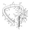
- FIG. 1is a perspective view of an embodiment of a clip for mounting a fluid delivery device in accordance with the invention mounted to a toilet bowl.
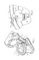
- FIG. 2is a perspective, fragmentary view taken along line 2 - 2 of FIG. 1 showing the clip of FIG. 1 .
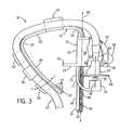
- FIG. 3is a side elevation view having a cutout showing a portion of the interior of the clip of FIG. 1 .
- FIG. 4is a rear oblique view of the clip of FIG. 1 .
- FIG. 5is a front view of a portion of the clip of FIG. 1 showing a hook of the clip in accordance with an embodiment of the invention.
- FIG. 6is a rear view of a portion of the clip of FIG. 1 showing a base of the clip in accordance with an embodiment of the invention.
- FIG. 7is a front view of the clip of FIG. 1 showing the clip in rotated (dashed lines) and non-rotated (solid lines) orientations.
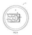
- FIG. 8is a top view of a portion of the nozzle of the clip taken along line 8 - 8 of FIG. 3 .
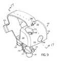
- FIG. 9is a perspective view of another embodiment of a clip for mounting a fluid delivery device in accordance with the invention.
- FIG. 10is a side view of the clip of FIG. 9 .
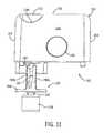
- FIG. 11is a front view of the clip of FIG. 9 with the hook removed.
- FIG. 12is a vertical cross-sectional view of the fluid inlet, nozzle and support arm of the clip of FIG. 9 .
- FIG. 13is a top view of a portion of the nozzle of the clip taken along line 13 - 13 of FIG. 10 .
- FIG. 14is a front elevational view of yet another nozzle suitable for use with the invention.
- FIG. 15is a side elevational view of the nozzle of FIG. 14 .
- FIG. 16is a side view of another hook suitable for use with the clip of FIG. 9 .
- FIG. 17is a cross-sectional view of the clip of FIG. 9 taken along line 17 - 17 of FIG. 9 .
- FIG. 18is a rear view of the clip of FIG. 9 with the hook removed.
- FIG. 19is a top view of the clip of FIG. 9 with the hook removed.
- FIG. 20is a cross-sectional view of the clip housing of FIG. 19 taken along line 20 - 20 of FIG. 19 .
- FIG. 21is a perspective view of the cross-sectional view of the clip housing of FIG. 20 .
- a clip according to the invention for mounting a fluid delivery devicecan be used in various devices that dispense fluid onto the inside surfaces of an enclosure, such as a toilet bowl, a shower enclosure, a bathtub enclosure, or the like.
- an enclosuresuch as a toilet bowl, a shower enclosure, a bathtub enclosure, or the like.
- FIGS. 1 and 2there is shown an example embodiment of a clip 10 for mounting a fluid delivery device to an enclosure, here a toilet bowl 12 .
- the clip 10is secured to the rim 14 of the toilet bowl 12 by a hook 16 .
- a base 18is supported by the hook 16 and houses a fluid delivery device, here a nozzle 20 .
- a container 22supplies fluid via a fluid conduit 24 to the fluid delivery device 20 to be dispensed onto the inside surface 26 of the toilet bowl 12 .
- the fluidcan be supplied from the container 22 to the fluid delivery device 20 in a variety of ways; for example, the fluid may be motivated by a gaseous propellant, by a pump, a syringe, or any other suitable means.
- the execution of the fluid delivery from the container 22can be controlled by a variety of methods/devices, one being a timing circuit using predetermined logic to control when the fluid is dispensed.
- the hook 16 for supporting the base 18 and attaching the clip 10 to the toilet bowl 12has three main segments.
- All three segments 28 , 30 , 32are preferably integrally molded from plastic (e.g., polyethylene or polypropylene) and form a flexible hook 16 .
- the bowl segment 28has a substantially rectangular cross-section and a flared elastomeric gripping foot 34 with elastomeric ribs 37 at a lower end for helping to secure the clip 10 to the toilet bowl 12 .
- Suitable elastomeric materials for the gripping foot 34 and ribs 37include, without limitation, neoprene, polyurethane rubbers, and silicone rubbers.
- the bowl segment 28extends substantially vertically upward and transitions into the top rim segment 30 at a flexible elbow 35 that allows the hook 16 to flex predominantly in the F-F direction (shown on FIG. 3 ) to secure the clip 10 to toilet bowls of various shapes and sizes.
- the top rim segment 30has a substantially rectangular cross-section and extends horizontal across the rim 14 of the toilet bowl 12 where it transitions into the inner rim segment 32 at another flexible elbow 36 , also allowing the hook 16 to flex.
- the inner rim segment 32extends vertically downward from the elbow 36 and is configured to engage and support the base 18 .
- the inner rim segment 32 of the hook 16has a front face 38 and a rear face 40 joined by two short side faces 42 .
- a rib 44protrudes from the rear face 40 of the inner rim segment 32 and extends the length thereof. As discussed in detail below, the rib 44 limits the angle of rotation of the base 18 with respect to the hook 16 .
- the rib 44 of the example embodimenthas a substantially rectangular cross-section, however, the rib 44 may have a curved cross-section, a square cross-section, comprise two spaced apart members, and the like. Additionally, the rib 44 need not extend the length of the inner rim segment 32 provided the rib 44 engages the base 18 throughout the desired adjustable range of the base 18 .
- the short side faces 42have ratchet teeth 46 used in conjunction with the base 18 to restrain vertical movement of the base 18 along a vertical axis 48 .
- Other restraintsmay be used, such as a friction fit between the hook 16 and base 18 , or the like.
- the bowl segment 28 and the top rim segment 30include a series of C-shaped channels 50 that restrain the conduit 24 as it is routed around the perimeter of the hook 16 on its way to the nozzle 20 in the base 18 .
- the bowl segment 28 of the present embodimentincludes three C-shaped channels 50 of alternating openings.
- the conduit 24is pressed into the C-shaped channels 50 , however, the channels 50 could be rectangular or any other suitable shape to restrain the conduit 24 .
- the top rim segment 30preferably includes one channel 50 helping to route the conduit 24 , however, more may be used if needed.
- the base 18has a back face 52 , a pair of spaced apart side faces 54 extending forward of the back face 52 , a top face 56 and a front face 58 extending between the side faces 54 , and a curved face 60 extending between the side faces 54 , top face 56 , and front face 58 .
- the faces 52 , 54 , 56 , 58 , 60define a partial cavity 62 housing a portion of the nozzle 20 .
- the base 18has a tab 53 that extends rearward from the back face 52 of the base 18 .
- the tab 53helps orientate the base 18 with respect to the rim 14 when the clip 10 is mounted to the toilet bowl 12 , as discussed below.
- the tab 53may be one continuous member as shown in the example embodiment, or alternatively, the tab 53 may include a plurality of members extending from the base 18 .
- the base 18is preferably molded from plastic (e.g., polyethylene or polypropylene).
- the base 18includes a channel 64 for receiving the inner rim segment 32 of the hook 16 .
- the channel 64includes a slit 66 for receiving the rib 44 having an entrance 68 , an exit 70 , and an intermediate position 72 (which may or may not be equidistant from the entrance 68 and the exit 70 ).
- the width of the slit 66decreases from the entrance 68 to the intermediate position 72 and increases from the intermediate position 72 to the exit 70 .
- the intermediate position 72is approximately half way between the entrance 68 and the exit 70 ; however, the narrowest point need not be halfway between the entrance 68 and exit 70 , but may occur anywhere between the extremes of the slit 66 .
- the maximum width of the slit 66may vary depending on the desired degree of adjustment of the base 18 with respect to the hook 16 . If greater rotational adjustment of the base 18 is desired, the maximum width of the slit 66 at the entrance 68 and exit 70 may be increased; alternatively, or in addition, the width of the rib 44 may be decreased.
- the channel 64includes a pair of projections 74 extending from the walls of the short sides 65 of the channel 64 to engage the ratchet teeth 46 of the hook 16 as the inner rim segment 32 slides within the channel 64 .
- the projections 74are configured to engage the ratchet teeth 46 to inhibit vertical sliding of the base 18 with respect to the hook 16 .
- the projections 74may be rounded, terminate in a point, or other suitable geometry. Many other structures are capable of providing the desired restraint, such as a spring-loaded ball that is housed in a cavity formed in the channel 64 to urge the ball against a contour (e.g., ratchet teeth 46 ) of the channel 64 .
- the engagement between the projections 74 and the ratchet teeth 46is such that the base 18 is capable of the desired rotation (discussed below) without causing the projections 74 and ratchet teeth 46 to disengage.
- the base 18further includes a means to attach a fluid delivery device (e.g., a nozzle 20 ).
- a fluid delivery devicee.g., a nozzle 20
- the nozzle 20is restrained laterally between a fluid inlet 80 and a barrel 78 .
- the base 18includes an arm 76 extending downward from the base 18 .
- the arm 76has a flat bar support segment 77 with a J-shaped bend extending forward with a barrel 78 located at the distal end of the support segment 77 .
- the barrel 78includes a tubular recess for receiving the bottom of the nozzle 20 .
- the base 18also has a fluid inlet 80 located in the curved face 60 that tapers from the opening (shown in FIG. 3 ).
- the fluid inlet 80 and the barrel 78are used in conjunction to restrain lateral movement of the nozzle 20 , but allow the nozzle 20 to rotate about the nozzle axis 82 .
- a sensor 98 for sensing the environment surrounding the clip 10may be mounted to the base 18 or hook 16 .
- the sensor 98is mounted substantially to the front face 58 , but may be mounted on the angled face 60 or any other suitable location providing a view, for example, of the user to accurately determine the presence or absence thereof.
- the sensor 98may be a motion sensor, proximity sensor, or the like.
- the sensor 98is preferably electrically connected to the container 22 and/or controller (not shown) to influence when the fluid is dispensed to the toilet bowl 12 based upon predetermined logic. It should be appreciated that the sensor can be omitted from the clip 10 in certain embodiments if the sensing function is not desired.
- the fluid delivery device 20is preferably molded from plastic (e.g., polyethylene and polypropylene).
- the nozzle 20includes a circular deflection plate 84 , a passageway 86 extending upwards from the deflection plate 84 and in fluid communication with the fluid inlet 80 .
- a channel 88extends radially outward from the passageway 86 near the deflection plate 84 and angles away from the initial channel 88 path at point A as shown in FIG. 8 .
- the channel 88is flanked by a pair of fins 90 that extend upwardly from the deflection plate 84 .
- the contour of the channel 88 and fins 90may vary depending on the desired rotational speed of the nozzle 20 , pressure of the fluid, and the like.
- the nozzle 20is restrained laterally in the base 18 by inserting a spindle 92 extending from the underside of the deflection plate 84 into the recess in the barrel 78 of the arm 76 and by inserting the tapered end of the fluid inlet 80 into the passageway 86 where it abuts a ledge 94 formed in the passageway 86 .
- the nozzle 20is free to rotate about the nozzle axis 82 , but is restrained from lateral movement.
- the means for attaching the fluid delivery devicemay include a fluid delivery device 20 suspended from the base 18 without the use of an arm 76 .
- the fluid delivery devicehere a nozzle 20
- the fluid delivery devicemay be snap-fit to the base 18 , screwed to the base 18 , wedged to the base 18 , and the like.
- an arcuate arm(not shown) may extend from the base 18 to support the fluid delivery device 20 .
- fluidis moved from the container 22 through the conduit 24 , which is routed through the channels 50 along the hook 16 , and into the fluid inlet 80 on the base 18 .
- Fluidflows into the top of the nozzle 20 , down the passageway 86 where it is directed radially outward by the channel 88 .
- the channel 88its path is altered by the angled fins 90 flanking the channel 88 .
- the reactioncauses the nozzle 20 to rotate counterclockwise as viewed in FIG. 8 .
- the fluidis expelled radially outward from the nozzle 20 onto the inside surface 26 of the toilet bowl 12 .
- the base 18can be rotated relative to the hook 16 about a horizontal axis 96 extending substantially normal from a plane defined by the vertical axis 48 and the back face 52 of the base 18 .
- the slit 66 formed in the channel 64is flared at the entrance 68 and exit 70 . This allows the base 18 to rotate near the intermediate position 72 about the horizontal axis 96 until the rib 44 protruding from the hook 16 abuts the slit sides 45 formed in the back face 52 .
- the means for rotating the base 18need not include a slit 66 as described.
- the back face 52may include several pairs of opposed fingers in the plane defined by the back face 52 for restraining the rotation of the rib 44 of the hook 16 .
- the opening between a pair of opposed fingers near the entrance and the opening of a pair of opposed fingers near the exitare larger than the opening between a pair of opposed fingers located between the entrance and exit fingers.
- the base 18is capable of rotating until the rib 44 engages the fingers near the entrance and exit.
- the slit 66may have a V-shape wherein the entrance tapers to the exit, or the opposite.
- the point of rotation of the base 18is located near the exit of the slit 66 , or smaller of the entrance and exit. Again, the rotation of the base 18 is limited by the rib 44 engaging the slit sides 45 .
- the rotational adjustment of the base 18may be performed manually by a user of the clip 10 or automatically as the clip 10 is mounted to the enclosure, here a toilet bowl 12 .
- the clip 10is mounted substantially as follows.
- the clip 10is secured to the rim 14 of the toilet bowl 12 by urging the hook 16 in the F-F direction away from the base 18 and placing the clip 10 over the rim 14 .
- the base 18is slid along the vertical axis 48 up the hook 16 and ratchet teeth 46 until the tab 53 engages the underside of the rim 14 .
- the base 18is rotated about the horizontal axis 96 , thus aligning the nozzle 20 with the plane of the underside of the rim 14 and helping to ensure that the fluid from the nozzle 20 is dispensed onto the inside surface 26 of the toilet bowl 12 (assuming the plane of the underside of the rim 14 is parallel with the plane defined by the topside of the rim 14 ).
- the tab 53may further include an elastomeric grip 51 protruding from the distal end of the tab 53 helping to secure the base 18 in its engaged position on the rim 14 .
- the base 18need not include a tab 53 ; in this embodiment, the base 18 may be manually rotated by the user to adjust the base 18 with respect to the hook 16 .
- FIGS. 9-13 and 17 - 21there is shown another example embodiment of a clip 110 for mounting a fluid delivery device to an enclosure such as a toilet bowl.
- the clip 110is secured to the rim of the toilet bowl by a hook 116 (which is omitted in the views of FIGS. 11 and 18 - 21 ) in the same manner as the clip 10 of FIGS. 1-8 .
- a base 118is supported by the hook 116 and supports a fluid delivery device, here a nozzle 120 .
- a containersupplies fluid via a fluid conduit to the fluid delivery device 120 to be dispensed onto the inside surface of the toilet bowl in the same manner as the clip 10 of FIGS. 1-8 .
- the fluidcan be supplied from the container to the fluid delivery device 120 in a variety of ways; for example, the fluid may be motivated by a gaseous propellant, by a manual or electric pump, a syringe, or any other suitable means. Furthermore, the execution of the fluid delivery from the container can be controlled by a variety of methods/devices, one being a timing circuit using predetermined logic to control when the fluid is dispensed.
- the hook 116 for supporting the base 118 and attaching the clip 110 to the toilet bowlhas three main segments.
- a bowl segment 128a top rim segment 130 , and an inner rim segment 132 .
- All three segments 128 , 130 , 132are preferably integrally molded from plastic (e.g., polyethylene or polypropylene) and form a flexible hook 116 .
- the bowl segment 128has a substantially rectangular cross-section and a flared elastomeric gripping foot 134 with elastomeric ribs 137 at a lower end for helping to secure the clip 110 to the toilet bowl in the same manner as the clip 10 of FIGS. 1-8 .
- Suitable elastomeric materials for the gripping foot 134 and ribs 137include, without limitation, neoprene, polyurethane rubbers, and silicone rubbers.
- the bowl segment 128extends substantially vertically upward and transitions into the top rim segment 130 at a flexible elbow 135 that allows the hook 116 to flex (as in the G direction shown on FIG. 17 ) to secure the clip 110 to toilet bowls of various shapes and sizes.
- the top rim segment 130has a substantially rectangular cross-section and extends horizontally across the rim of the toilet bowl where it transitions into the inner rim segment 132 at another flexible elbow 136 , also allowing the hook 116 to flex.
- the inner rim segment 132extends vertically downward from the elbow 136 and is configured to engage and support the base 118 .
- the bowl segment 128 and the top rim segment 130include a C-shaped channel 150 that restrains the fluid conduit as it is routed around the perimeter of the hook 116 on its way to the nozzle 120 in the base 118 .
- the fluid conduitis pressed into the C-shaped channel 150 in the same manner as the clip 10 of FIGS. 1-8 .
- the base 118has a back face 152 , a pair of spaced apart side faces 154 extending forward of the back face 152 , a top face 156 and a front face 158 extending between the side faces 154 .
- the faces 152 , 154 , 156 , 158define a cavity.
- the base 118is preferably molded from plastic (e.g., polyethylene or polypropylene).
- FIGS. 17 , 19 , 20 and 21engagement of centrally located, linearly aligned dome-shaped projections 173 of the hook 116 and central arcuate ridges 175 a , 175 b , 175 c , 175 d , 175 e , 175 f on the inner surface 171 of the back wall of the base 118 keep the base 118 vertically restrained on the hook 116 .
- the base 118includes a channel 164 for receiving the inner rim segment 132 of the hook 116 .
- the channel 164is dimensioned to be complementary to the inner rim segment 132 of the hook 116 such that the inner rim segment 132 of the hook 116 can slide in the channel 164 with the application of force to the hook 116 .
- a recess 166 in the inner side of the channel 164receives the rib 144 of the hook 116 .
- the recess 166terminates in a back wall 167 .
- the lowermost of the group of six of the dome-shaped projections 173rides over the ridge 175 b and into a channel 174 b between the ridges 175 b and 175 c
- the dome-shaped projection adjacent and above the lowermost of the group of six of the dome-shaped projections 173rides over the ridge 175 a and into the concave channel 174 a between the ridges 175 a and 175 b .
- the lowermost of the group of six of the dome-shaped projections 173rides over the rounded top surface of ridges 175 c , 175 d , and 175 e respectively and into concave channels 174 c , 174 d , 174 e .
- the trailing dome-shaped projectionsride over ridges and move into channels sequentially.
- the base 118can be vertically restrained on the hook 116 until a further downward force is placed on the hook 116 and the dome-shaped projections 173 ride downward over an adjacent ridge.
- the clip 110includes means for rotating the base 118 and thus adjusting the area covered by the fluid dispensed from the nozzle 120 .
- the base 118can be rotated relative to the hook 116 about a horizontal axis 196 extending substantially normal from a plane defined by the vertical axis 148 and the back face 152 of the base 118 .
- Recess 166is formed in a channel 164 which is flared at the entrance 168 and exit 170 . This allows the base 118 to rotate near the intermediate position 172 about the horizontal axis 196 until the rib 144 protruding from the hook 116 abuts the recess sides 145 formed in the base 118 .
- ridges 175 a , 175 b , 175 c , 175 d , 175 e , 175 fhave been illustrated herein, it should appreciated that the use of one or more ridges can be suitable for vertical and rotational adjustment of the base 118 on the hook 116 .
- the rotational adjustment of the base 118may be performed manually by a user of the clip 110 or automatically as the clip 110 is mounted to the enclosure (e.g., a toilet bowl).
- the clip 110is secured to the rim of the toilet bowl by urging the hook 116 in the G direction (see FIG. 17 ) away from the base 118 and placing the clip 110 over the rim. Once the hook 116 is secured, the base 118 is slid along the vertical axis 148 up the hook 116 until the tab 153 engages the underside of the rim.
- the base 118is rotated about the horizontal axis 196 , thus aligning the nozzle 120 with the plane of the underside of the rim and helping to ensure that the fluid from the nozzle 120 is dispensed onto the inside surface of the toilet bowl.
- the tab 153may further include an elastomeric grip 151 protruding from the distal end of the tab 153 helping to secure the base 118 in its engaged position on the rim.
- the base 118need not include a tab 153 ; in this embodiment, the base 118 may be manually rotated by the user to adjust the base 118 with respect to the hook 116 .
- the hook 116includes a protruding tab 157 that limits movement of the end of the hook 116 above the underside 159 of the base 118 .
- a sensor 198 for sensing the environment surrounding the clip 110may be mounted to the base 118 .
- the sensor 198is mounted substantially to the front face 158 , but may be mounted on any other suitable location providing a view, for example, of the user to accurately determine the presence or absence thereof.
- the sensor 198may be a motion sensor, proximity sensor, or the like.
- the sensor 198is preferably electrically connected to the container and/or controller (not shown) to influence when the fluid is dispensed to the toilet bowl based upon predetermined logic.
- the base 118further includes a means to attach a fluid delivery device (e.g., nozzle 120 ) to the base 118 .
- a fluid delivery devicee.g., nozzle 120
- the nozzle 120is restrained laterally between a barrel 178 and a fluid inlet 180 .
- the base 118includes an arm 176 extending downward from the base 118 .
- the arm 176has a curved section 177 with a J-shaped bend extending forward to the barrel 178 located at the distal end of the curved section 177 .
- the fluid inlet 180 and the barrel 178are used in conjunction to restrain lateral movement of the nozzle 120 , but allow the nozzle 120 to rotate about the nozzle axis 182 .
- the tubular fluid inlet 180defines a flow path 181 , and extends downwardly from a lower base floor 202 that is attached to the base 118 .
- the base floor 202includes an upwardly extending tubular sleeve 204 that defines a flow path 205 .
- the base 118is also attached to a fluid supply port 208 that defines a flow path 209 .
- the fluid supply port 208 and the tubular sleeve 204are snap fit together with an O-ring 211 therebetween to create fluid tight seal.
- the fluid supply port 208is located in a recess 213 in the top face 156 of the base, and may be connected to a fluid conduit (such as conduit 24 in FIG. 3 ).
- the nozzle 120is shown in greater detail.
- the nozzle 120is preferably molded from plastic (e.g., polyethylene and polypropylene).
- the nozzle 120includes a circular deflection plate 184 .
- An axial spindle 192extends downward from the deflection plate 184 .
- Spaced apart walls 190 a , 190 bwhich have a generally inverted T-shape, extend upward from the deflection plate 184 .
- the walls 190 a , 190 bextend all the way across the deflection plate 184 from opposed outer edges of the deflection plate 184 .
- a central fluid deflection peak 191extends upward from the deflection plate 184 between the walls 190 a , 190 b .
- the top of the wall 190 ahas a generally U-shaped (when viewed in vertical cross-section) inwardly directed depression 193 a
- the top of the wall 190 bhas a generally U-shaped (when viewed in vertical cross-section) inwardly directed depression 193 b .
- a passageway 186is defined by the walls 190 a , 190 b and the passageway 186 extends upwards from the deflection plate 184 and in is fluid communication with the depressions 193 a , 193 b .
- a channel 188 Lextends radially outward from the passageway 186 near the deflection plate 184 and angles rearwardly away from the initial channel 188 L path at point A as shown in FIG. 13 .
- a channel 188 Rextends radially outward from the passageway 186 near the deflection plate 184 and angles forwardly away from the initial channel 188 R path at point B as shown in FIG. 13 .
- the contour of the channels 188 L, 188 R and walls 190 a , 190 bmay vary depending on the desired rotational speed of the nozzle 120 , the pressure of the fluid, the flow rate of the fluid, and the like.
- the nozzle 120is restrained laterally by inserting a spindle 192 into a recess 179 in the barrel 178 of the arm 176 and by inserting the end of the fluid inlet 180 between depressions 193 a , 193 b .
- the nozzle 120is free to rotate about the nozzle axis 182 , but is restrained from lateral movement.
- fluidis moved from a container through a fluid conduit (see, for example, the container 22 and the conduit 24 of FIG. 1 ) and into the fluid supply port 208 .
- the fluidflows through the flow paths 209 , 205 , and 181 , and out of the fluid inlet 180 .
- the diameter of the exit orifice of the fluid inletcan dictate the pressure which helps to dictate the spin rate and the distance of fluid travel off the nozzle 120 .
- Fluidflows onto the top of the fluid deflection peak 191 and down the forked passageways 186 where it is directed radially outward by the channels 188 L, 188 R.
- the fluid pathis altered by the angled inner surfaces 197 L, 197 R flanking the channels 188 L, 188 R.
- the reactioncauses the nozzle 120 to rotate counterclockwise as viewed in FIG. 13 .
- the fluidis expelled radially outward from the nozzle 120 onto the inside surface of the enclosure such as a toilet bowl.
- the nozzle 220is preferably molded from plastic (e.g., polyethylene and polypropylene).
- the nozzle 220includes a circular (from a top view) deflection plate 284 .
- An axial spindle 292extends downward from the deflection plate 284 .
- Spaced apart walls 290 a , 290 bwhich have a generally inverted T-shape, extend upward from the deflection plate 284 .
- the walls 290 a , 290 bextend from a location spaced inward from an outer edge point 277 L of the deflection plate 284 to a location spaced inward from an outer edge point 277 R of the deflection plate 284 .
- a central fluid deflection peak 291(similar to fluid deflection peak 191 of FIGS. 12 and 13 ) extends upward from the deflection plate 284 between the walls 290 a , 290 b .
- the top of the wall 290 ahas a generally U-shaped inwardly directed depression (similar to inwardly directed depression 193 a in FIGS. 12 and 13 ), and the top of the wall 290 b has a generally U-shaped inwardly directed depression (similar to inwardly directed depression 193 b in FIGS. 12 and 13 ).
- a passageway 286(similar to passageway 186 in FIGS. 12 and 13 ) is defined by the walls 290 a , 290 b and the passageway 286 extends upwards from the deflection plate 284 and in is fluid communication with the depressions in the walls 290 a , 290 b .
- a channel(similar to channel 188 L in FIGS. 12 and 13 ) extends radially outward from the passageway 286 near the deflection plate 284 and angles rearwardly away from the initial channel as in FIG. 13 .
- a channel 288 Rextends radially outward from the passageway 286 (similar to channel 188 R in FIGS.
- the deflection plate 284has a dished floor 276 that creates a draft angle Z (see FIG. 14 ) at the outer edge of the top of the deflection plate 284 .
- the contour of the draft angle Z, the channels, and the walls 290 a , 290 bmay vary depending on the desired rotational speed of the nozzle 220 , the pressure of the fluid, the flow rate of the fluid, and the like.
- the nozzle 220may be restrained laterally by inserting the spindle 292 into a recess 179 in the barrel 178 of the arm 176 and by inserting the end of the fluid inlet 180 between upper depressions in the walls 290 a , 290 b .
- the nozzle 220is free to rotate about the nozzle axis, but is restrained from lateral movement.
- fluidis moved from a container through a fluid conduit (see, for example, the container 22 and the conduit 24 of FIG. 1 ) and into the fluid supply port 208 as in FIG. 12 , the fluid flows through the flow paths 209 , 205 , and 181 , and out of the fluid inlet 180 .
- Fluidflows onto the top of the fluid deflection peak 291 of nozzle 220 and down the forked passageways 286 where it is directed onto the floor 276 and radially outward by the channels.
- the fluid pathis altered by the angled inner surfaces of the walls 290 a , 290 b flanking the channels.
- the reactioncauses the nozzle 220 to rotate right in direction R as in FIG. 15 .
- the fluidcontinues to flow on the floor 276 and then moves up the draft angle at the edge of the deflection plate 284 to create a slightly upward travel path for the fluid.
- the fluidis expelled radially outward from the nozzle 220 onto the inside surface of the toilet bowl, with the slightly upward travel path for the fluid allowing for under the toilet rim contact of the fluid with the inner surface of the toilet bowl even after 18 or more inches of travel.
- the nozzle 20 , the nozzle 120 , and the nozzle 220have differences in structure that can lead to different operating characteristics.
- the nozzle 20has a single channel 88 extending away from the passageway 86
- nozzle 120 and nozzle 220have two channels extending away from the central passageway.
- the extra passagewaycan serve to get maximum work out of the nozzle and improve efficiency.
- the nozzle 120 and nozzle 220also have fluid deflection peaks 191 , 291 that can improve efficiency.
- nozzle 120 and nozzle 220Comparing nozzle 120 and nozzle 220 , it can be seen that the walls 190 a , 190 b of nozzle 120 extend all the way across the deflection plate 184 from opposed outer edges of the deflection plate 184 , whereas walls 290 a , 290 b of nozzle 220 are spaced inward from opposed outer edges of the deflection plate 284 .
- the spacing of the walls from the edge of the platecan create more tangential motion in the fluid expelled from the nozzle 220 .
- the centripetal forcecauses fluid to spin and shear off.
- the draft angle Z at the outer edge of the nozzle 220can provide for a spray of about 18 inches without having the level of liquid spray drop down. This is advantageous as it prevents the spray from failing down so far that it does not hit under the upper areas under the toilet rim.
- nozzles 20 , 120 , 220can be varied depending on the application for the nozzles. For example, in a nozzle suitable for use in a toilet cleaning device, fluid flow is downward unto the deflection plate to create a spray that moves downward less quickly after leaving the surface of the deflection plate.
- the design parameters of the nozzles 20 , 120 , 220can be varied to accommodate lower fluid pressures, such as 10 to 20 psi (69 to 138 kilopascals), and fluid travel paths of less than 24 inches (0.6096 meters), and flow rates below 10 gallons per hour (37.85 liters per hour).
- the operating parameters of pressure, volume, and flow ratecan be accommodated by varying the design of the nozzles 20 , 120 , 220 .
- Fluid pressures of 14 to 15 psi (96 to 103 kilopascals) and fluid travels paths of up to 18 inches (0.4572 meters)are most preferred in a toilet application.
- FIG. 16there is shown a side view of another hook 216 suitable for use with the clip of FIG. 9 .
- the hook 216has three main segments, i.e., a bowl segment 228 , a top rim segment 230 , and an inner rim segment 232 . All three segments 228 , 230 , 232 are preferably molded from plastic (e.g., polyethylene or polypropylene).
- the bowl segment 128has a substantially rectangular cross-section and a flared elastomeric gripping foot 234 with oblong elastomeric ribs 237 at a lower end for helping to secure the hook 216 to the toilet bowl in the same manner as the clip 10 of FIGS. 1-8 .
- Suitable elastomeric materials for the gripping foot 234 and ribs 237include, without limitation, neoprene, polyurethane rubbers, and silicone rubbers.
- the bowl segment 228extends substantially vertically upward and transitions into the top rim segment 230 at a flexible elbow 235 that allows the hook 216 to flex.
- the top rim segment 230has a substantially rectangular cross-section and extends horizontally across the rim of the toilet bowl.
- the inner rim segment 232 of the hook 216is configured to engage and support the base 118 as described above with reference to the embodiment of the clip 110 of FIGS. 9-15 .
- the upper end of the inner rim segment 232has a lateral generally rectangular passageway 236 that extends through the inner rim segment 232 .
- a distal end 238 of the top rim segment 230is inserted in the passageway 236 such that the bowl segment 228 and the inner rim segment 232 are movable toward and away from each other.
- This horizontal expansion and contraction of the hook 216further accommodates various toilet bowl rim width sizes.
- the inner surface of the bowl segment 228includes a suction cup 239
- the inner surface of the top rim segment 230includes a suction cup 241 .
- the bowl segment 228may be adhered to the toilet rim 14 by suction cup 239
- the top rim segment 230may be adhered to the toilet rim 14 by suction cup 241 .
- the present inventionprovides a clip for mounting a fluid delivery device where the base of the clip is rotatable relative to the hook such that fluid is dispensed onto the inner surface of the enclosure, and further, where a sensor prevents dispensing fluid at undesired periods.
- a sensorprevents dispensing fluid at undesired periods.
- the present inventionprovides a clip for mounting a fluid delivery device where the base of the clip is rotatable relative to the hook such that fluid is dispensed onto the inner surface of the enclosure, and further, where a sensor prevents dispensing fluid at undesired periods.
Landscapes
- Health & Medical Sciences (AREA)
- Public Health (AREA)
- Epidemiology (AREA)
- Life Sciences & Earth Sciences (AREA)
- Engineering & Computer Science (AREA)
- Hydrology & Water Resources (AREA)
- Water Supply & Treatment (AREA)
- Bidet-Like Cleaning Device And Other Flush Toilet Accessories (AREA)
Abstract
Description
Claims (19)
Priority Applications (8)
| Application Number | Priority Date | Filing Date | Title |
|---|---|---|---|
| US11/800,488US20070240252A1 (en) | 2005-12-20 | 2007-05-04 | Clip for mounting a fluid delivery device |
| US11/831,653US8291524B2 (en) | 2005-12-20 | 2007-07-31 | Clip for mounting a fluid delivery device |
| AU2008248219AAU2008248219B2 (en) | 2007-05-04 | 2008-05-02 | Clip for mounting a fluid delivery device |
| JP2010507412AJP5113246B2 (en) | 2007-05-04 | 2008-05-02 | Clip for mounting fluid ejection device |
| EP08767491AEP2148959A1 (en) | 2007-05-04 | 2008-05-02 | Clip for mounting a fluid delivery device |
| PCT/US2008/005643WO2008137045A1 (en) | 2005-12-20 | 2008-05-02 | Clip for mounting a fluid delivery device |
| US12/142,942US20090000016A1 (en) | 2005-12-20 | 2008-06-20 | Toilet Bowl Cleaning And/Or Deodorizing Device |
| US12/581,264US20100071121A1 (en) | 2005-12-20 | 2009-10-19 | Toilet Bowl Cleaning and/or Deodorizing Device |
Applications Claiming Priority (6)
| Application Number | Priority Date | Filing Date | Title |
|---|---|---|---|
| US11/312,281US7603726B2 (en) | 2005-12-20 | 2005-12-20 | Toilet bowl cleaning and/or deodorizing device |
| US11/800,501US20080272200A1 (en) | 2007-05-04 | 2007-05-04 | Rotary sprayer for a fluid delivery device |
| US11/800,493US8099800B2 (en) | 2005-12-20 | 2007-05-04 | Toilet bowl cleaning and/or deodorizing device |
| US11/800,488US20070240252A1 (en) | 2005-12-20 | 2007-05-04 | Clip for mounting a fluid delivery device |
| US11/749,558US8500044B2 (en) | 2007-05-04 | 2007-05-16 | Multiple nozzle differential fluid delivery head |
| US11/831,653US8291524B2 (en) | 2005-12-20 | 2007-07-31 | Clip for mounting a fluid delivery device |
Related Parent Applications (1)
| Application Number | Title | Priority Date | Filing Date |
|---|---|---|---|
| US11/800,488Continuation-In-PartUS20070240252A1 (en) | 2005-12-20 | 2007-05-04 | Clip for mounting a fluid delivery device |
Related Child Applications (1)
| Application Number | Title | Priority Date | Filing Date |
|---|---|---|---|
| US12/142,942Continuation-In-PartUS20090000016A1 (en) | 2005-12-20 | 2008-06-20 | Toilet Bowl Cleaning And/Or Deodorizing Device |
Publications (2)
| Publication Number | Publication Date |
|---|---|
| US20080017762A1 US20080017762A1 (en) | 2008-01-24 |
| US8291524B2true US8291524B2 (en) | 2012-10-23 |
Family
ID=46206180
Family Applications (1)
| Application Number | Title | Priority Date | Filing Date |
|---|---|---|---|
| US11/831,653Expired - Fee RelatedUS8291524B2 (en) | 2005-12-20 | 2007-07-31 | Clip for mounting a fluid delivery device |
Country Status (2)
| Country | Link |
|---|---|
| US (1) | US8291524B2 (en) |
| WO (1) | WO2008137045A1 (en) |
Cited By (4)
| Publication number | Priority date | Publication date | Assignee | Title |
|---|---|---|---|---|
| US20120110722A1 (en)* | 2010-11-09 | 2012-05-10 | Matthew Abbondanzio | Clip for Mounting a Fluid Delivery Device |
| US10669705B2 (en) | 2016-07-05 | 2020-06-02 | Willert Home Products, Inc. | Toilet bowl treatment apparatus and method of making same |
| US10989427B2 (en) | 2017-12-20 | 2021-04-27 | Trane International Inc. | HVAC system including smart diagnostic capabilites |
| US12227930B2 (en)* | 2021-09-30 | 2025-02-18 | Kobayashi Pharmaceutical Co., Ltd. | Chemical feeding device |
Families Citing this family (14)
| Publication number | Priority date | Publication date | Assignee | Title |
|---|---|---|---|---|
| US20100071121A1 (en) | 2005-12-20 | 2010-03-25 | Kissner William R | Toilet Bowl Cleaning and/or Deodorizing Device |
| JP5121536B2 (en)* | 2008-03-31 | 2013-01-16 | 小林製薬株式会社 | Chemical supply device |
| US20110088153A1 (en)* | 2009-10-19 | 2011-04-21 | Jesse Richard | Non-contact spray toilet bowl cleaning device |
| US8359676B2 (en) | 2009-10-19 | 2013-01-29 | S.C. Johnson & Son, Inc. | Relatively compact non-contact spray toilet bowl cleaning device |
| USD665486S1 (en)* | 2010-09-03 | 2012-08-14 | Kobayashi Pharmaceutical Co., Ltd. | Air freshener container for toilet paper holder |
| USD667944S1 (en) | 2010-11-09 | 2012-09-25 | S.C. Johnson & Son, Inc. | Dispenser mounting device |
| USD649235S1 (en)* | 2010-11-09 | 2011-11-22 | S.C. Johnson & Son, Inc. | Container holder |
| USD643101S1 (en) | 2010-11-26 | 2011-08-09 | S.C. Johnson & Son, Inc. | Sprayer for a fluid delivery device |
| US8549675B2 (en) | 2010-11-26 | 2013-10-08 | S.C. Johnson & Son, Inc. | Toilet bowl cleaning device including dual activation mechanism |
| WO2013044033A1 (en) | 2011-09-21 | 2013-03-28 | Ari Kahn | Universal ring free |
| US20170140307A1 (en)* | 2014-06-27 | 2017-05-18 | o9 Solutions, Inc. | Plan modeling and task management |
| US9848743B1 (en) | 2016-08-12 | 2017-12-26 | Reuven Shabat | Toilet maintenance devices and system |
| US10724219B2 (en)* | 2018-12-10 | 2020-07-28 | Beatris Huitron | Automatic toilet bowl cleaning apparatus and methods |
| GB202306659D0 (en)* | 2023-05-05 | 2023-06-21 | Richardson Jason | Apparatus for the control of a flow of a liquid |
Citations (115)
| Publication number | Priority date | Publication date | Assignee | Title |
|---|---|---|---|---|
| US1366426A (en) | 1920-05-06 | 1921-01-25 | Silvers Samuel | Delivery device for liquid disinfectants |
| US2075266A (en) | 1934-01-16 | 1937-03-30 | Earle L Bowman | Disinfecting dispensing apparatus |
| US2166772A (en) | 1937-03-28 | 1939-07-18 | Salsas-Serra Francisco | Atomizer for liquids |
| US2397677A (en) | 1943-08-11 | 1946-04-02 | E C Macglashan | Liquid feeding device |
| US2444441A (en)* | 1946-11-04 | 1948-07-06 | Grinham Fred | Deodorizer for toilet bowls |
| US2614265A (en) | 1948-08-24 | 1952-10-21 | Vierra Antone Nunes | Disinfecting device |
| US2760209A (en) | 1954-03-22 | 1956-08-28 | James W Ewing | Container for toilet disinfectant and deodorant |
| US3088125A (en) | 1961-03-30 | 1963-05-07 | Dewey R Southwood | Fluid dispenser |
| US3128018A (en) | 1961-07-07 | 1964-04-07 | Drackett Co | Fluid dispensing pump with sealing means |
| US3178070A (en) | 1963-02-15 | 1965-04-13 | Ragnvald G Leland | Toilet bowl deodorizer |
| GB1140900A (en) | 1966-11-10 | 1969-01-22 | James William Ewing | Toilet hygienic device |
| US3940027A (en) | 1973-08-30 | 1976-02-24 | Firma Rudolf Brand | Dispenser for a bottle top |
| US3946448A (en) | 1973-11-02 | 1976-03-30 | Mekopharma Dr. Becker & Cie. K.G. | Apparatus for disinfection and chemical purification of toilet bowls |
| US3953902A (en) | 1975-01-17 | 1976-05-04 | Colgate-Palmolive Company | Water closet additive means |
| US4072247A (en) | 1976-02-19 | 1978-02-07 | Nippon Glass Measure Co., Ltd. | Liquid dispensing device |
| US4183105A (en) | 1977-11-03 | 1980-01-15 | Womack Leo K | Self-cleaning toilet |
| US4273257A (en) | 1977-07-18 | 1981-06-16 | Sherwood Medical Industries Inc. | Jar mounted pipettor |
| US4407217A (en) | 1982-03-29 | 1983-10-04 | Jaybee Engineering Pty. Limited | Distribution and treatment means |
| US4530108A (en)* | 1981-07-16 | 1985-07-16 | Itt Industries Inc. | Counter for non-volatile storage |
| USRE32017E (en) | 1978-04-24 | 1985-11-05 | Globol-Werk Gmbh | Toilet flush water colorizer |
| US4560108A (en) | 1983-04-20 | 1985-12-24 | Zvi Rubinstein | Sprinkler |
| US4562867A (en) | 1978-11-13 | 1986-01-07 | Bowles Fluidics Corporation | Fluid oscillator |
| US4618077A (en) | 1984-03-07 | 1986-10-21 | Corsette Douglas Frank | Liquid dispensing pump |
| FR2588742A1 (en) | 1985-10-17 | 1987-04-24 | Collomp Raymond | Apparatus dispensing a deodorising and disinfecting product precisely when a toilet is being used |
| US4660765A (en) | 1984-07-20 | 1987-04-28 | Peretz Rosenberg | Water sprinkler |
| US4670916A (en) | 1985-11-20 | 1987-06-09 | Sitting Pretty, Inc. | Toilet bowl dispenser |
| US4747523A (en) | 1987-06-19 | 1988-05-31 | Calmar, Inc. | Manually actuated dispensing pump |
| EP0274785A1 (en) | 1986-12-18 | 1988-07-20 | Struyk Beheer B.V. | Toilet for public use |
| US4763839A (en) | 1986-01-31 | 1988-08-16 | Plastro Gvat | Water sprinkler |
| US4777670A (en) | 1988-01-13 | 1988-10-18 | S. C. Johnson & Son, Inc. | Under-the-rim dispensing unit |
| US4817869A (en) | 1984-10-24 | 1989-04-04 | Zvi Rubinstein | Rotating miniature sprinkler for irrigation systems |
| JPH0197423A (en) | 1987-10-09 | 1989-04-14 | Daiki Kk | Deodorizing device for flush toilet bowl |
| US4873729A (en) | 1983-11-18 | 1989-10-17 | Jacques Micallef | Automatic device for the disinfection of W.C. bowls and seats |
| US4905903A (en)* | 1987-07-31 | 1990-03-06 | Gardena Kress & Kastner Gmbh | Sprinkler |
| JPH039714A (en) | 1989-06-08 | 1991-01-17 | Teisa Sangyo Kk | Spray controlling circuit for closet seat germ-removing device |
| US5022098A (en) | 1989-11-02 | 1991-06-11 | Richard Brower | Automatic, self-cleaning, water saving, toilet system |
| JPH03228718A (en) | 1990-02-02 | 1991-10-09 | Hikoma Seisakusho Kk | Automatic feeding device for chemical liquid to toilet bowl |
| US5123124A (en) | 1989-11-02 | 1992-06-23 | Richard Brower | Automatic, self-cleaning, water saving, toilet system |
| US5143293A (en) | 1990-09-24 | 1992-09-01 | Pairis Raul R | Mist-producing device |
| US5203506A (en) | 1991-12-16 | 1993-04-20 | Product Development (Z.G.S.) Ltd. | Liquid pump and nebulizer constructed therewith |
| JPH05222757A (en) | 1992-02-10 | 1993-08-31 | Inax Corp | Deodorizing stool |
| US5347661A (en) | 1993-07-01 | 1994-09-20 | Fly Howard G | Water conditioner dispensing apparatus |
| US5457822A (en) | 1991-07-30 | 1995-10-17 | Kuyus Stiftung | Device for dispensing disinfectant, cleaning agent and/or scent into a toilet bowl |
| US5862532A (en)* | 1997-05-05 | 1999-01-26 | Cain; Martin | Quick spray dispenser |
| US5906298A (en) | 1997-06-30 | 1999-05-25 | Ward; Thomas A. | Scent dispersal system |
| DE29811823U1 (en) | 1998-06-08 | 1999-10-21 | Yankee Polish Lüth GmbH + Co, 21465 Reinbek | Toilet basket |
| US6000067A (en)* | 1998-04-07 | 1999-12-14 | Cascia; Frank J. | Automatic liquid chemical additive dispenser for recreational vehicle toilets |
| WO1999066140A1 (en) | 1998-06-15 | 1999-12-23 | S.C. Johnson & Son, Inc. | Liquid dispenser |
| WO1999066139A1 (en) | 1998-06-15 | 1999-12-23 | S.C. Johnson & Son, Inc. | Dispensing liquids |
| US6015067A (en) | 1997-01-27 | 2000-01-18 | Brand Gmbh + Co. | Bottle top dispenser |
| US6016972A (en) | 1997-05-30 | 2000-01-25 | Dan Mamtirim | Bridgeless rotary sprinkler |
| US6029286A (en) | 1998-05-14 | 2000-02-29 | Funk; Cameron | Odor removing apparatus for toilets |
| JP2000166818A (en) | 1998-12-02 | 2000-06-20 | Inax Corp | Seating sensor of private part cleaning device |
| US6162371A (en) | 1997-12-22 | 2000-12-19 | S. C. Johnson & Son, Inc. | Stabilized acidic chlorine bleach composition and method of use |
| US6178563B1 (en) | 1999-03-29 | 2001-01-30 | Leon Helfet | Toilet deodorizer |
| US6178564B1 (en) | 1999-12-14 | 2001-01-30 | S. C. Johnson & Son, Inc. | Liquid dispensing toilet rim mounted toilet bowl cleaner |
| WO2001014652A1 (en) | 1999-08-25 | 2001-03-01 | Skarboe Kjell | Device for neutralising odour in lavatory |
| US6230334B1 (en) | 1999-04-19 | 2001-05-15 | Sara Lee/De N.V. | Cleansing and freshening unit intended for suspension from a rim of a toilet bowl |
| WO2001044591A1 (en) | 1999-12-14 | 2001-06-21 | S.C. Johnson & Son, Inc. | Improved liquid dispensing toilet bowl cleaner |
| US6279174B1 (en) | 1994-08-25 | 2001-08-28 | Aldo Candusso | Flushing, cleaning device for service of sanitary fixtures |
| JP3228718B2 (en) | 1999-02-04 | 2001-11-12 | オリンパス光学工業株式会社 | Endoscope |
| US6347414B2 (en) | 2000-02-04 | 2002-02-19 | Waterbury Companies, Inc. | Intelligent demand-based dispensing system |
| US6394310B1 (en) | 1999-09-15 | 2002-05-28 | Kenneth J. Muderlak | System and method for programmably dispensing material |
| JP2002180518A (en) | 2000-12-11 | 2002-06-26 | Aisin Seiki Co Ltd | Toilet seat device |
| US6425406B1 (en) | 1999-09-14 | 2002-07-30 | S. C. Johnson & Son, Inc. | Toilet bowl cleaning method |
| US20020130146A1 (en) | 2001-03-14 | 2002-09-19 | Borut Severine N. | Automatic air freshener with dynamically variable dispensing interval |
| JP2002286833A (en) | 2001-03-22 | 2002-10-03 | Toto Ltd | Mounting structure of doppler sensor |
| US20020148908A1 (en) | 2001-04-13 | 2002-10-17 | Linstedt Brian K. | Automated cleansing sprayer |
| US6471974B1 (en) | 1999-06-29 | 2002-10-29 | S.C. Johnson & Son, Inc. | N-chlorosulfamate compositions having enhanced antimicrobial efficacy |
| US6494384B1 (en) | 2001-04-06 | 2002-12-17 | Nelson Irrigation Corporation | Reversible and adjustable part circle sprinkler |
| US20030056587A1 (en) | 2001-09-19 | 2003-03-27 | Carpenter M. Scott | Thermochromatic indicator for an aersol container |
| US6588026B2 (en) | 1999-05-27 | 2003-07-08 | Hts International Trading Ag | Method of, and apparatus for, introducing a cleaning agent and/or disinfectant into sanitary facilities |
| US20030188377A1 (en) | 2002-04-09 | 2003-10-09 | Contadini Carl D. | Dispensing system |
| US6651261B1 (en) | 2002-07-19 | 2003-11-25 | S. C. Johnson & Son, Inc. | Toilet rim mounted toilet cleaner with extension plate |
| US6675396B2 (en) | 1999-12-14 | 2004-01-13 | S. C. Johnson & Son, Inc. | Liquid dispensing toilet bowl cleaner |
| US6691329B2 (en)* | 2000-11-02 | 2004-02-17 | Brian Parry Slade | Liquid delivery devices |
| US6694536B1 (en) | 2002-08-14 | 2004-02-24 | Basil Haygreen | Fragrant water closet closer |
| US6702157B1 (en) | 2003-02-26 | 2004-03-09 | Saint-Gobain Calmar Inc. | Self-aligning pump assembly |
| US20040050959A1 (en) | 2002-05-28 | 2004-03-18 | Mazooji Amber N. | Automated cleansing sprayer |
| JP2004100212A (en) | 2002-09-06 | 2004-04-02 | Inax Corp | Toilet facility |
| FR2850407A1 (en) | 2003-01-27 | 2004-07-30 | Andre Cluzel | Security retainer for deodorant container on water closet reservoir has suction cup with strap to connected to container |
| US6772450B1 (en)* | 2003-10-09 | 2004-08-10 | Tom Saylor | Toilet bowl cleaning apparatus |
| EP1449969A2 (en) | 2003-02-24 | 2004-08-25 | Joseph Szabo | Support device for a dispenser for a WC deodorant |
| JP2004283811A (en) | 2003-03-19 | 2004-10-14 | Kankyo Create:Kk | Discharge nozzle |
| US6812196B2 (en) | 2000-06-05 | 2004-11-02 | S.C. Johnson & Son, Inc. | Biocidal cleaner composition containing acid-anionic surfactant-alcohol combinations and method of using the composition |
| US20050005378A1 (en) | 2003-07-08 | 2005-01-13 | Soller Douglas A. | Cleaning brush with disposable/replaceable brush head |
| JP2005103367A (en) | 2003-09-29 | 2005-04-21 | Matsushita Electric Ind Co Ltd | Spray nozzle |
| US6898806B2 (en) | 2002-10-01 | 2005-05-31 | Skot S.A. Chemical Products | Device for dispensing a liquid active substance |
| US20050133540A1 (en) | 2003-12-18 | 2005-06-23 | Hornsby James R. | Power sprayer |
| WO2005070474A1 (en) | 2004-01-23 | 2005-08-04 | Reckitt Benckiser (Uk) Limited | Device for dispensing a fluid |
| JP2005211164A (en) | 2004-01-27 | 2005-08-11 | Matsushita Electric Works Ltd | Toilet system |
| US6932279B2 (en) | 2003-10-27 | 2005-08-23 | Senninger Irrigation Inc. | Wobbling sprinkler head |
| US6944890B1 (en) | 2005-01-25 | 2005-09-20 | Sim Jac K | Automatic cleaning assembly for a toilet bowl |
| US6971549B2 (en) | 2003-04-18 | 2005-12-06 | S.C. Johnson & Son, Inc. | Bottle adapter for dispensing of cleanser from bottle used in an automated cleansing sprayer |
| JP2005344300A (en) | 2004-05-31 | 2005-12-15 | Matsushita Electric Works Ltd | Toilet seat device |
| US6976277B2 (en) | 2002-10-01 | 2005-12-20 | Skot S.A. Chemical Products | Device for dispensing a liquid active substance |
| US20060006253A1 (en) | 2004-07-07 | 2006-01-12 | Nelson Irrigation Corporation | Two-axis full-circle sprinkler with bent, rotating nozzle |
| WO2006013321A1 (en) | 2004-08-04 | 2006-02-09 | Reckitt Benckiser Inc | Dispensing device |
| FR2874038A1 (en) | 2004-08-05 | 2006-02-10 | Supratech | Toilet for public or private usage, has bowl cleaning device including duct that presents section allowing, in operation, injection of cleaning product in bowl in distributed manner |
| US7021494B2 (en) | 2003-04-18 | 2006-04-04 | S. C. Johnson & Son, Inc. | Automated cleansing sprayer having separate cleanser and air vent paths from bottle |
| US7114199B2 (en) | 2003-04-25 | 2006-10-03 | S.C. Johnson & Son, Inc. | Toilet rim mounted device for dispensing two liquids |
| US20070000941A1 (en) | 2005-07-01 | 2007-01-04 | Hadden David M | Motion-activated soap dispenser |
| US20070040045A1 (en) | 2003-07-15 | 2007-02-22 | Boaz Cohen | Rotary sprinkler with reduced wear |
| US20070045337A1 (en) | 2005-06-24 | 2007-03-01 | Hornsby James R | Dispensing device |
| US20070136937A1 (en) | 2005-12-20 | 2007-06-21 | Sawalski Michael M | Toilet bowl cleaning and/or deodorizing device |
| US20070158359A1 (en) | 2005-12-08 | 2007-07-12 | Rodrian James A | Method and Apparatus for Controlling a Dispenser and Detecting a User |
| US20070187427A1 (en) | 2006-02-14 | 2007-08-16 | Shaw Robert K | Universal hub for a fluid dispenser |
| US20070204389A1 (en) | 2004-09-03 | 2007-09-06 | Ingeborg Graefe | Fastening clip for releasably fastening a dispensing device for dispensing active substances into the flushing liquid on a downward pointing edge element of a toilet bowl, and dispensing device provided with a fastening clip of this type |
| US20070204388A1 (en) | 2006-03-06 | 2007-09-06 | Greg Zyskowski | Automated remote bathroom air freshener |
| US20070240252A1 (en) | 2005-12-20 | 2007-10-18 | Leonard Stephen B | Clip for mounting a fluid delivery device |
| US20070240251A1 (en) | 2004-07-14 | 2007-10-18 | Re Le Vi. -S.P.A | W.C. Dispenser with Perfuming Chamber |
| US20070289054A1 (en) | 2006-06-16 | 2007-12-20 | Joseph Han | Toilet bowl cleanser dispenser device |
| US20080078780A1 (en) | 2006-10-03 | 2008-04-03 | Sanger Nancy S | Automatic dispenser |
| WO2008044201A2 (en) | 2006-10-13 | 2008-04-17 | The Procter & Gamble Company | A unit-dose detergent dispenser with fragrancing component |
| WO2008076346A2 (en) | 2006-12-14 | 2008-06-26 | Bowles Fluidics Corporation | Full coverage fluidic oscillator with automated cleaning system and method |
Family Cites Families (2)
| Publication number | Priority date | Publication date | Assignee | Title |
|---|---|---|---|---|
| US423257A (en)* | 1890-03-11 | Carburetor | ||
| JP4803994B2 (en)* | 2004-11-12 | 2011-10-26 | キヤノン株式会社 | Image forming apparatus |
- 2007
- 2007-07-31USUS11/831,653patent/US8291524B2/ennot_activeExpired - Fee Related
- 2008
- 2008-05-02WOPCT/US2008/005643patent/WO2008137045A1/enactiveApplication Filing
Patent Citations (124)
| Publication number | Priority date | Publication date | Assignee | Title |
|---|---|---|---|---|
| US1366426A (en) | 1920-05-06 | 1921-01-25 | Silvers Samuel | Delivery device for liquid disinfectants |
| US2075266A (en) | 1934-01-16 | 1937-03-30 | Earle L Bowman | Disinfecting dispensing apparatus |
| US2166772A (en) | 1937-03-28 | 1939-07-18 | Salsas-Serra Francisco | Atomizer for liquids |
| US2397677A (en) | 1943-08-11 | 1946-04-02 | E C Macglashan | Liquid feeding device |
| US2444441A (en)* | 1946-11-04 | 1948-07-06 | Grinham Fred | Deodorizer for toilet bowls |
| US2614265A (en) | 1948-08-24 | 1952-10-21 | Vierra Antone Nunes | Disinfecting device |
| US2760209A (en) | 1954-03-22 | 1956-08-28 | James W Ewing | Container for toilet disinfectant and deodorant |
| US3088125A (en) | 1961-03-30 | 1963-05-07 | Dewey R Southwood | Fluid dispenser |
| US3128018A (en) | 1961-07-07 | 1964-04-07 | Drackett Co | Fluid dispensing pump with sealing means |
| US3178070A (en) | 1963-02-15 | 1965-04-13 | Ragnvald G Leland | Toilet bowl deodorizer |
| GB1140900A (en) | 1966-11-10 | 1969-01-22 | James William Ewing | Toilet hygienic device |
| US3940027A (en) | 1973-08-30 | 1976-02-24 | Firma Rudolf Brand | Dispenser for a bottle top |
| US3946448A (en) | 1973-11-02 | 1976-03-30 | Mekopharma Dr. Becker & Cie. K.G. | Apparatus for disinfection and chemical purification of toilet bowls |
| US3953902A (en) | 1975-01-17 | 1976-05-04 | Colgate-Palmolive Company | Water closet additive means |
| US4072247A (en) | 1976-02-19 | 1978-02-07 | Nippon Glass Measure Co., Ltd. | Liquid dispensing device |
| US4273257A (en) | 1977-07-18 | 1981-06-16 | Sherwood Medical Industries Inc. | Jar mounted pipettor |
| US4183105A (en) | 1977-11-03 | 1980-01-15 | Womack Leo K | Self-cleaning toilet |
| USRE32017E (en) | 1978-04-24 | 1985-11-05 | Globol-Werk Gmbh | Toilet flush water colorizer |
| US4562867A (en) | 1978-11-13 | 1986-01-07 | Bowles Fluidics Corporation | Fluid oscillator |
| US4530108A (en)* | 1981-07-16 | 1985-07-16 | Itt Industries Inc. | Counter for non-volatile storage |
| US4407217A (en) | 1982-03-29 | 1983-10-04 | Jaybee Engineering Pty. Limited | Distribution and treatment means |
| US4560108A (en) | 1983-04-20 | 1985-12-24 | Zvi Rubinstein | Sprinkler |
| US4873729A (en) | 1983-11-18 | 1989-10-17 | Jacques Micallef | Automatic device for the disinfection of W.C. bowls and seats |
| US4618077A (en) | 1984-03-07 | 1986-10-21 | Corsette Douglas Frank | Liquid dispensing pump |
| US4660765A (en) | 1984-07-20 | 1987-04-28 | Peretz Rosenberg | Water sprinkler |
| US4817869A (en) | 1984-10-24 | 1989-04-04 | Zvi Rubinstein | Rotating miniature sprinkler for irrigation systems |
| FR2588742A1 (en) | 1985-10-17 | 1987-04-24 | Collomp Raymond | Apparatus dispensing a deodorising and disinfecting product precisely when a toilet is being used |
| US4670916A (en) | 1985-11-20 | 1987-06-09 | Sitting Pretty, Inc. | Toilet bowl dispenser |
| US4763839A (en) | 1986-01-31 | 1988-08-16 | Plastro Gvat | Water sprinkler |
| EP0274785A1 (en) | 1986-12-18 | 1988-07-20 | Struyk Beheer B.V. | Toilet for public use |
| US4747523A (en) | 1987-06-19 | 1988-05-31 | Calmar, Inc. | Manually actuated dispensing pump |
| US4905903A (en)* | 1987-07-31 | 1990-03-06 | Gardena Kress & Kastner Gmbh | Sprinkler |
| JPH0197423A (en) | 1987-10-09 | 1989-04-14 | Daiki Kk | Deodorizing device for flush toilet bowl |
| US4777670A (en) | 1988-01-13 | 1988-10-18 | S. C. Johnson & Son, Inc. | Under-the-rim dispensing unit |
| JPH039714A (en) | 1989-06-08 | 1991-01-17 | Teisa Sangyo Kk | Spray controlling circuit for closet seat germ-removing device |
| US5123124A (en) | 1989-11-02 | 1992-06-23 | Richard Brower | Automatic, self-cleaning, water saving, toilet system |
| US5022098A (en) | 1989-11-02 | 1991-06-11 | Richard Brower | Automatic, self-cleaning, water saving, toilet system |
| JPH03228718A (en) | 1990-02-02 | 1991-10-09 | Hikoma Seisakusho Kk | Automatic feeding device for chemical liquid to toilet bowl |
| US5143293A (en) | 1990-09-24 | 1992-09-01 | Pairis Raul R | Mist-producing device |
| US5457822A (en) | 1991-07-30 | 1995-10-17 | Kuyus Stiftung | Device for dispensing disinfectant, cleaning agent and/or scent into a toilet bowl |
| US5203506A (en) | 1991-12-16 | 1993-04-20 | Product Development (Z.G.S.) Ltd. | Liquid pump and nebulizer constructed therewith |
| JPH05222757A (en) | 1992-02-10 | 1993-08-31 | Inax Corp | Deodorizing stool |
| US5347661A (en) | 1993-07-01 | 1994-09-20 | Fly Howard G | Water conditioner dispensing apparatus |
| US6279174B1 (en) | 1994-08-25 | 2001-08-28 | Aldo Candusso | Flushing, cleaning device for service of sanitary fixtures |
| US6015067A (en) | 1997-01-27 | 2000-01-18 | Brand Gmbh + Co. | Bottle top dispenser |
| US5862532A (en)* | 1997-05-05 | 1999-01-26 | Cain; Martin | Quick spray dispenser |
| US6016972A (en) | 1997-05-30 | 2000-01-25 | Dan Mamtirim | Bridgeless rotary sprinkler |
| US5906298A (en) | 1997-06-30 | 1999-05-25 | Ward; Thomas A. | Scent dispersal system |
| US6162371A (en) | 1997-12-22 | 2000-12-19 | S. C. Johnson & Son, Inc. | Stabilized acidic chlorine bleach composition and method of use |
| US6000067A (en)* | 1998-04-07 | 1999-12-14 | Cascia; Frank J. | Automatic liquid chemical additive dispenser for recreational vehicle toilets |
| US6029286A (en) | 1998-05-14 | 2000-02-29 | Funk; Cameron | Odor removing apparatus for toilets |
| DE29811823U1 (en) | 1998-06-08 | 1999-10-21 | Yankee Polish Lüth GmbH + Co, 21465 Reinbek | Toilet basket |
| US6505356B1 (en) | 1998-06-15 | 2003-01-14 | S. C. Johnson & Son, Inc. | Dispensing liquids |
| WO1999066139A1 (en) | 1998-06-15 | 1999-12-23 | S.C. Johnson & Son, Inc. | Dispensing liquids |
| WO1999066140A1 (en) | 1998-06-15 | 1999-12-23 | S.C. Johnson & Son, Inc. | Liquid dispenser |
| JP2000166818A (en) | 1998-12-02 | 2000-06-20 | Inax Corp | Seating sensor of private part cleaning device |
| JP3228718B2 (en) | 1999-02-04 | 2001-11-12 | オリンパス光学工業株式会社 | Endoscope |
| US6178563B1 (en) | 1999-03-29 | 2001-01-30 | Leon Helfet | Toilet deodorizer |
| US6230334B1 (en) | 1999-04-19 | 2001-05-15 | Sara Lee/De N.V. | Cleansing and freshening unit intended for suspension from a rim of a toilet bowl |
| US6588026B2 (en) | 1999-05-27 | 2003-07-08 | Hts International Trading Ag | Method of, and apparatus for, introducing a cleaning agent and/or disinfectant into sanitary facilities |
| US6471974B1 (en) | 1999-06-29 | 2002-10-29 | S.C. Johnson & Son, Inc. | N-chlorosulfamate compositions having enhanced antimicrobial efficacy |
| WO2001014652A1 (en) | 1999-08-25 | 2001-03-01 | Skarboe Kjell | Device for neutralising odour in lavatory |
| US6425406B1 (en) | 1999-09-14 | 2002-07-30 | S. C. Johnson & Son, Inc. | Toilet bowl cleaning method |
| US6394310B1 (en) | 1999-09-15 | 2002-05-28 | Kenneth J. Muderlak | System and method for programmably dispensing material |
| US6769580B2 (en) | 1999-09-15 | 2004-08-03 | Technical Concepts, Llc | System and method for programmably dispensing material |
| WO2001044591A1 (en) | 1999-12-14 | 2001-06-21 | S.C. Johnson & Son, Inc. | Improved liquid dispensing toilet bowl cleaner |
| US6675396B2 (en) | 1999-12-14 | 2004-01-13 | S. C. Johnson & Son, Inc. | Liquid dispensing toilet bowl cleaner |
| US6178564B1 (en) | 1999-12-14 | 2001-01-30 | S. C. Johnson & Son, Inc. | Liquid dispensing toilet rim mounted toilet bowl cleaner |
| US6347414B2 (en) | 2000-02-04 | 2002-02-19 | Waterbury Companies, Inc. | Intelligent demand-based dispensing system |
| US6812196B2 (en) | 2000-06-05 | 2004-11-02 | S.C. Johnson & Son, Inc. | Biocidal cleaner composition containing acid-anionic surfactant-alcohol combinations and method of using the composition |
| US6691329B2 (en)* | 2000-11-02 | 2004-02-17 | Brian Parry Slade | Liquid delivery devices |
| JP2002180518A (en) | 2000-12-11 | 2002-06-26 | Aisin Seiki Co Ltd | Toilet seat device |
| US20020130146A1 (en) | 2001-03-14 | 2002-09-19 | Borut Severine N. | Automatic air freshener with dynamically variable dispensing interval |
| JP2002286833A (en) | 2001-03-22 | 2002-10-03 | Toto Ltd | Mounting structure of doppler sensor |
| US6494384B1 (en) | 2001-04-06 | 2002-12-17 | Nelson Irrigation Corporation | Reversible and adjustable part circle sprinkler |
| US20020148908A1 (en) | 2001-04-13 | 2002-10-17 | Linstedt Brian K. | Automated cleansing sprayer |
| US6820821B2 (en) | 2001-04-13 | 2004-11-23 | S.C. Johnson & Son, Inc. | Automated cleansing sprayer |
| US20030056587A1 (en) | 2001-09-19 | 2003-03-27 | Carpenter M. Scott | Thermochromatic indicator for an aersol container |
| US6739479B2 (en) | 2002-04-09 | 2004-05-25 | Waterbury Companies, Inc. | Dispensing system |
| US20030188377A1 (en) | 2002-04-09 | 2003-10-09 | Contadini Carl D. | Dispensing system |
| US20040050959A1 (en) | 2002-05-28 | 2004-03-18 | Mazooji Amber N. | Automated cleansing sprayer |
| US6651261B1 (en) | 2002-07-19 | 2003-11-25 | S. C. Johnson & Son, Inc. | Toilet rim mounted toilet cleaner with extension plate |
| US6694536B1 (en) | 2002-08-14 | 2004-02-24 | Basil Haygreen | Fragrant water closet closer |
| JP2004100212A (en) | 2002-09-06 | 2004-04-02 | Inax Corp | Toilet facility |
| US6976277B2 (en) | 2002-10-01 | 2005-12-20 | Skot S.A. Chemical Products | Device for dispensing a liquid active substance |
| US6898806B2 (en) | 2002-10-01 | 2005-05-31 | Skot S.A. Chemical Products | Device for dispensing a liquid active substance |
| FR2850407A1 (en) | 2003-01-27 | 2004-07-30 | Andre Cluzel | Security retainer for deodorant container on water closet reservoir has suction cup with strap to connected to container |
| EP1449969A2 (en) | 2003-02-24 | 2004-08-25 | Joseph Szabo | Support device for a dispenser for a WC deodorant |
| US6702157B1 (en) | 2003-02-26 | 2004-03-09 | Saint-Gobain Calmar Inc. | Self-aligning pump assembly |
| JP2004283811A (en) | 2003-03-19 | 2004-10-14 | Kankyo Create:Kk | Discharge nozzle |
| US6971549B2 (en) | 2003-04-18 | 2005-12-06 | S.C. Johnson & Son, Inc. | Bottle adapter for dispensing of cleanser from bottle used in an automated cleansing sprayer |
| US7021494B2 (en) | 2003-04-18 | 2006-04-04 | S. C. Johnson & Son, Inc. | Automated cleansing sprayer having separate cleanser and air vent paths from bottle |
| US7114199B2 (en) | 2003-04-25 | 2006-10-03 | S.C. Johnson & Son, Inc. | Toilet rim mounted device for dispensing two liquids |
| US20050005378A1 (en) | 2003-07-08 | 2005-01-13 | Soller Douglas A. | Cleaning brush with disposable/replaceable brush head |
| US20070040045A1 (en) | 2003-07-15 | 2007-02-22 | Boaz Cohen | Rotary sprinkler with reduced wear |
| JP2005103367A (en) | 2003-09-29 | 2005-04-21 | Matsushita Electric Ind Co Ltd | Spray nozzle |
| US6772450B1 (en)* | 2003-10-09 | 2004-08-10 | Tom Saylor | Toilet bowl cleaning apparatus |
| US6932279B2 (en) | 2003-10-27 | 2005-08-23 | Senninger Irrigation Inc. | Wobbling sprinkler head |
| US20050133540A1 (en) | 2003-12-18 | 2005-06-23 | Hornsby James R. | Power sprayer |
| WO2005070474A1 (en) | 2004-01-23 | 2005-08-04 | Reckitt Benckiser (Uk) Limited | Device for dispensing a fluid |
| US20070204387A1 (en) | 2004-01-23 | 2007-09-06 | Reckitt Benckiser (Uk) Limited | Device for Dispensing a Fluid |
| JP2005211164A (en) | 2004-01-27 | 2005-08-11 | Matsushita Electric Works Ltd | Toilet system |
| JP2005344300A (en) | 2004-05-31 | 2005-12-15 | Matsushita Electric Works Ltd | Toilet seat device |
| US20060006253A1 (en) | 2004-07-07 | 2006-01-12 | Nelson Irrigation Corporation | Two-axis full-circle sprinkler with bent, rotating nozzle |
| US7143957B2 (en) | 2004-07-07 | 2006-12-05 | Nelson Irrigation Corporation | Two-axis full-circle sprinkler with bent, rotating nozzle |
| US20070240251A1 (en) | 2004-07-14 | 2007-10-18 | Re Le Vi. -S.P.A | W.C. Dispenser with Perfuming Chamber |
| WO2006013321A1 (en) | 2004-08-04 | 2006-02-09 | Reckitt Benckiser Inc | Dispensing device |
| US20070245470A1 (en) | 2004-08-04 | 2007-10-25 | Reckitt Benckiser Inc. | Dispensing Device |
| FR2874038A1 (en) | 2004-08-05 | 2006-02-10 | Supratech | Toilet for public or private usage, has bowl cleaning device including duct that presents section allowing, in operation, injection of cleaning product in bowl in distributed manner |
| US20070204389A1 (en) | 2004-09-03 | 2007-09-06 | Ingeborg Graefe | Fastening clip for releasably fastening a dispensing device for dispensing active substances into the flushing liquid on a downward pointing edge element of a toilet bowl, and dispensing device provided with a fastening clip of this type |
| US6944890B1 (en) | 2005-01-25 | 2005-09-20 | Sim Jac K | Automatic cleaning assembly for a toilet bowl |
| US7007312B1 (en) | 2005-01-25 | 2006-03-07 | Sim Jae K | Automatic cleaning assembly for a toilet bowl |
| US20070045337A1 (en) | 2005-06-24 | 2007-03-01 | Hornsby James R | Dispensing device |
| US20070000941A1 (en) | 2005-07-01 | 2007-01-04 | Hadden David M | Motion-activated soap dispenser |
| US20070158359A1 (en) | 2005-12-08 | 2007-07-12 | Rodrian James A | Method and Apparatus for Controlling a Dispenser and Detecting a User |
| US20070240252A1 (en) | 2005-12-20 | 2007-10-18 | Leonard Stephen B | Clip for mounting a fluid delivery device |
| US20070136937A1 (en) | 2005-12-20 | 2007-06-21 | Sawalski Michael M | Toilet bowl cleaning and/or deodorizing device |
| US7603726B2 (en)* | 2005-12-20 | 2009-10-20 | S.C. Johnson & Son, Inc. | Toilet bowl cleaning and/or deodorizing device |
| US20070187427A1 (en) | 2006-02-14 | 2007-08-16 | Shaw Robert K | Universal hub for a fluid dispenser |
| US20070204388A1 (en) | 2006-03-06 | 2007-09-06 | Greg Zyskowski | Automated remote bathroom air freshener |
| US20070289054A1 (en) | 2006-06-16 | 2007-12-20 | Joseph Han | Toilet bowl cleanser dispenser device |
| US20080078780A1 (en) | 2006-10-03 | 2008-04-03 | Sanger Nancy S | Automatic dispenser |
| WO2008044201A2 (en) | 2006-10-13 | 2008-04-17 | The Procter & Gamble Company | A unit-dose detergent dispenser with fragrancing component |
| WO2008076346A2 (en) | 2006-12-14 | 2008-06-26 | Bowles Fluidics Corporation | Full coverage fluidic oscillator with automated cleaning system and method |
Non-Patent Citations (23)
| Title |
|---|
| English Language Abstract of FR 2588742, Apr. 24, 1987. |
| English Language Abstract of FR 2874038, May 8, 2004. |
| English Language Abstract of JP 1-97423, Apr. 14, 1989. |
| English Language Abstract of JP 3-228718, Oct. 9, 1991. |
| English Language Abstract of JP 3-9714, Jan. 17, 1991. |
| English Language Machine Translation of JP 2000-166818, Jun. 20, 2000. |
| English Language Machine Translation of JP 2002-048884, Feb. 15, 2002. |
| English Language Machine Translation of JP 2002-180518, Jun. 26, 2002. |
| English Language Machine Translation of JP 2002-286833, Oct. 3, 2002. |
| English Language Machine Translation of JP 2004-100212, Apr. 2, 2004. |
| English Language Machine Translation of JP 2004-283811, Oct. 14, 2004. |
| English Language Machine Translation of JP 2005-103367, Apr. 21, 2005. |
| English Language Machine Translation of JP 2005-211164, Aug. 11, 2005. |
| English Language Machine Translation of JP 2005-344300, Dec. 15, 2005. |
| English Language Machine Translation of JP 2005-36511, Feb. 10, 2005. |
| English Language Machine Translation of JP 2005-46769, Feb. 24, 2005. |
| English Language Machine Translation of JP 2005-52754, Mar. 3, 2005. |
| English Language Machine Translation of JP 5-222757, Aug. 31, 1993. |
| English Language Translation of JP 2000-70797, Mar. 7, 2000. |
| English Language Translation of JP 6-170286, Jun. 21, 1994. |
| Microsprinkler shown at www.dripirrigation.com, 3 pages, May 3, 2007. |
| Non-Final Office Action mailed Aug. 12, 2011 in the parent U.S. Appl. No. 11/800,488. |
| PCT/US2008/005643 International Search Report and Written Opinion dated Aug. 25, 2008. |
Cited By (5)
| Publication number | Priority date | Publication date | Assignee | Title |
|---|---|---|---|---|
| US20120110722A1 (en)* | 2010-11-09 | 2012-05-10 | Matthew Abbondanzio | Clip for Mounting a Fluid Delivery Device |
| US10669705B2 (en) | 2016-07-05 | 2020-06-02 | Willert Home Products, Inc. | Toilet bowl treatment apparatus and method of making same |
| US10989427B2 (en) | 2017-12-20 | 2021-04-27 | Trane International Inc. | HVAC system including smart diagnostic capabilites |
| US11708982B2 (en) | 2017-12-20 | 2023-07-25 | Trane International Inc. | HVAC system including smart diagnostic capabilities |
| US12227930B2 (en)* | 2021-09-30 | 2025-02-18 | Kobayashi Pharmaceutical Co., Ltd. | Chemical feeding device |
Also Published As
| Publication number | Publication date |
|---|---|
| US20080017762A1 (en) | 2008-01-24 |
| WO2008137045A1 (en) | 2008-11-13 |
Similar Documents
| Publication | Publication Date | Title |
|---|---|---|
| US8291524B2 (en) | Clip for mounting a fluid delivery device | |
| US20070240252A1 (en) | Clip for mounting a fluid delivery device | |
| US8099800B2 (en) | Toilet bowl cleaning and/or deodorizing device | |
| US20080272200A1 (en) | Rotary sprayer for a fluid delivery device | |
| US20090000016A1 (en) | Toilet Bowl Cleaning And/Or Deodorizing Device | |
| US8359676B2 (en) | Relatively compact non-contact spray toilet bowl cleaning device | |
| US20110088153A1 (en) | Non-contact spray toilet bowl cleaning device | |
| US20090249533A1 (en) | Toilet Bowl Cleaning and/or Deodorizing Device | |
| US8549675B2 (en) | Toilet bowl cleaning device including dual activation mechanism | |
| US20120110722A1 (en) | Clip for Mounting a Fluid Delivery Device | |
| US20100071121A1 (en) | Toilet Bowl Cleaning and/or Deodorizing Device | |
| US20120174304A1 (en) | Toilet Bowl Cleaning Device Including Container Retention Mechanism | |
| AU2008248219B2 (en) | Clip for mounting a fluid delivery device | |
| WO2008137044A1 (en) | Device for spraying fluids with a rotary sprayer | |
| AU2008248180A1 (en) | Multiple nozzle differential fluid delivery head |
Legal Events
| Date | Code | Title | Description |
|---|---|---|---|
| AS | Assignment | Owner name:BIT 7, INC., WISCONSIN Free format text:ASSIGNMENT OF ASSIGNORS INTEREST;ASSIGNOR:CRULL, JEFFREY L.;REEL/FRAME:028155/0613 Effective date:20070814 Owner name:COMPUTIME LIMITED, HONG KONG Free format text:ASSIGNMENT OF ASSIGNORS INTEREST;ASSIGNOR:SHUM, WAI YIN;REEL/FRAME:028155/0668 Effective date:20070913 Owner name:S.C. JOHNSON & SON, INC., WISCONSIN Free format text:ASSIGNMENT OF ASSIGNORS INTEREST;ASSIGNORS:LEONARD, STEPHEN B.;MILLER, ALLEN D.;SAWALSKI, MICHAEL M.;AND OTHERS;SIGNING DATES FROM 20070810 TO 20070906;REEL/FRAME:028155/0466 Owner name:FLOMETRICS, INC., CALIFORNIA Free format text:ASSIGNMENT OF ASSIGNORS INTEREST;ASSIGNOR:HARRINGTON, STEVEN MERRILL;REEL/FRAME:028155/0540 Effective date:20070823 Owner name:S.C. JOHNSON & SON, INC., WISCONSIN Free format text:ASSIGNMENT OF ASSIGNORS INTEREST;ASSIGNOR:FLOMETRICS, INC.;REEL/FRAME:028155/0573 Effective date:20070823 Owner name:S.C. JOHNSON & SON, INC., WISCONSIN Free format text:ASSIGNMENT OF ASSIGNORS INTEREST;ASSIGNOR:BIT 7, INC.;REEL/FRAME:028155/0627 Effective date:20070813 Owner name:S.C. JOHNSON & SON, INC., WISCONSIN Free format text:ASSIGNMENT OF ASSIGNORS INTEREST;ASSIGNOR:COMPUTIME LIMITED;REEL/FRAME:028155/0686 Effective date:20070920 | |
| STCF | Information on status: patent grant | Free format text:PATENTED CASE | |
| FPAY | Fee payment | Year of fee payment:4 | |
| FEPP | Fee payment procedure | Free format text:MAINTENANCE FEE REMINDER MAILED (ORIGINAL EVENT CODE: REM.); ENTITY STATUS OF PATENT OWNER: LARGE ENTITY | |
| LAPS | Lapse for failure to pay maintenance fees | Free format text:PATENT EXPIRED FOR FAILURE TO PAY MAINTENANCE FEES (ORIGINAL EVENT CODE: EXP.); ENTITY STATUS OF PATENT OWNER: LARGE ENTITY | |
| STCH | Information on status: patent discontinuation | Free format text:PATENT EXPIRED DUE TO NONPAYMENT OF MAINTENANCE FEES UNDER 37 CFR 1.362 | |
| FP | Lapsed due to failure to pay maintenance fee | Effective date:20201023 |