US8291131B2 - Data transfer management - Google Patents
Data transfer managementDownload PDFInfo
- Publication number
- US8291131B2 US8291131B2US12/498,151US49815109AUS8291131B2US 8291131 B2US8291131 B2US 8291131B2US 49815109 AUS49815109 AUS 49815109AUS 8291131 B2US8291131 B2US 8291131B2
- Authority
- US
- United States
- Prior art keywords
- data transfer
- memory
- characteristic
- controller
- bandwidth
- Prior art date
- Legal status (The legal status is an assumption and is not a legal conclusion. Google has not performed a legal analysis and makes no representation as to the accuracy of the status listed.)
- Active, expires
Links
Images


Classifications
- G—PHYSICS
- G06—COMPUTING OR CALCULATING; COUNTING
- G06F—ELECTRIC DIGITAL DATA PROCESSING
- G06F13/00—Interconnection of, or transfer of information or other signals between, memories, input/output devices or central processing units
- G06F13/14—Handling requests for interconnection or transfer
- G06F13/20—Handling requests for interconnection or transfer for access to input/output bus
- G06F13/28—Handling requests for interconnection or transfer for access to input/output bus using burst mode transfer, e.g. direct memory access DMA, cycle steal
- G—PHYSICS
- G06—COMPUTING OR CALCULATING; COUNTING
- G06F—ELECTRIC DIGITAL DATA PROCESSING
- G06F12/00—Accessing, addressing or allocating within memory systems or architectures
- G—PHYSICS
- G06—COMPUTING OR CALCULATING; COUNTING
- G06F—ELECTRIC DIGITAL DATA PROCESSING
- G06F13/00—Interconnection of, or transfer of information or other signals between, memories, input/output devices or central processing units
- G06F13/14—Handling requests for interconnection or transfer
- G—PHYSICS
- G06—COMPUTING OR CALCULATING; COUNTING
- G06F—ELECTRIC DIGITAL DATA PROCESSING
- G06F13/00—Interconnection of, or transfer of information or other signals between, memories, input/output devices or central processing units
- G06F13/14—Handling requests for interconnection or transfer
- G06F13/16—Handling requests for interconnection or transfer for access to memory bus
Definitions
- HDDhard disk drive
- HDDsare capable of large amounts of storage at relatively low cost, with current consumer HDDs available with over one terabyte of capacity.
- HDDsgenerally store data on rotating magnetic media or platters.
- the resulting data signalis an analog signal whose peaks and valleys are a consequence of the magnetic flux reversals of the data pattern.
- HDDshave certain drawbacks due to their mechanical nature. HDDs are susceptible to damage or excessive read write errors due to shock, vibration or strong magnetic fields. In addition, they are relatively large users of power in portable electronic devices.
- SSDsutilize semiconductor memory devices to store their data, often including an interface and form factor that makes them appear to their host system as if they are a typical HDD.
- the memory devices of SSDsmay comprise non-volatile flash memory devices.
- FIG. 1is a diagram illustrating a system for managing data writes to a solid state drive (SSD), according to various embodiments of the invention
- FIG. 2is a diagram illustrating an SSD configured to manage data writes, according to various embodiments of the invention
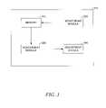
- FIG. 3is a diagram illustrating modules of an SSD controller configured to manage data writes, according to various embodiments of the invention
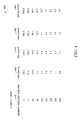
- FIG. 4is a table illustrating lists of some variables involved in managing data writes to an SSD, according to various embodiments of the invention.
- FIG. 5is a graph illustrating changes in the variables of the table shown in FIG. 4 , according to various embodiments of the invention.
- FIG. 6is a state diagram illustrating implementation of an algorithm for SSD data write management, according to various embodiments of the invention.
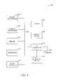
- FIG. 7is a flow diagram illustrating a method of SSD data write management, according to various embodiments of the invention.
- FIG. 8is a diagram illustrating an example system for managing SSD data writes, according to various embodiments of the invention.
- Some example embodiments described hereinmay include monitoring a data transfer (e.g., a data write) between a host and a memory.
- the data transfer profilemay be assessed and an assessment result may be provided.
- a future data transfermay be adjusted based on the assessment result.
- a data transfer profilecomprises, for example, one or more values associated with, for example, the sizes of the data transfers (e.g., number of bytes transferred), write amplification value, and write bandwidth, as will be described in more detail below.
- FIG. 1is a diagram illustrating a system 100 for managing data writes to a solid state drive (SSD) 110 , according to various embodiments of the invention.
- the system 100may include a SSD 110 in communication with a memory access device such as a processor 120 .
- the system 100may be considered a host system of the SSD 110 in that it controls the operation of the SSD 110 through, for example, the processor 120 .
- the system 100may employ one or more applications (host applications) to access the SSD 110 .
- Some examples of system 100may include personal computers, laptop computers, personal digital assistants (PDAs), digital cameras, electronic games, digital media player/recorders, and the like.
- PDAspersonal digital assistants
- the processor 120may comprise a disk drive controller or other external processor.
- the processor 120may communicate with the SSD 110 via a communication bus 130 .
- the communication bus 130may employ a known protocol to connect the processor 120 to the SSD 110 .
- the type of communication bus 130may depend on the type of drive interface being utilized in the system 100 . Examples of some conventional disk drive interface bus protocols are Integrated Drive Electronics (IDE), Advanced Technology Attachment (ATA), Serial ATA (SATA), Parallel ATA (PATA), Fiber Channel and Small Computer System Interface (SCSI). Other drive interfaces exist and are known in the art.
- the memory devices of the SSD 110may include non-volatile flash memory devices. A more detailed description of features of the SSD 110 , as related to data write management, will be given below.
- FIG. 2is a diagram illustrating the SSD 10 configured to manage data writes, according to various embodiments of the invention.
- the SSD 110may include a controller 210 coupled to an interface 230 that allows communication with a host (e.g., the processor 120 of FIG. 1 , or a host application) via the communication bus 130 ( FIG. 1 ).
- the interface 230may be one of many connectors commonly known to those of ordinary skill in the art. Some example of theses interface 230 connectors may include IDE, enhanced IDE, ATA, SATA, and Personal Computer Memory Card International Association (PCMCIA) connectors.
- PCMCIAPersonal Computer Memory Card International Association
- the memory in the SSD 110may be organized into multiple storage units 220 each comprising one or more memory devices, such as flash memory devices. Memory locations in memory devices may be grouped into blocks. In flash memory devices, blocks having storage capacities of 128 kilobytes (KB), 256 KB and 512 KB are common.
- the hostmay not be aware of which flash memory devices are currently being addressed for data read/write operations. In other words, the host is not aware of any physical block address (PBA) that is accessed in an actual data transfer (e.g., read or write).
- PBAphysical block address
- the hostmerely deals with a logical block address (LBA), which is translated into a PBA. This translation from LBA to PBA may occur within the SSD 110 , after the SSD 110 receives a request for data transfer specifying a logical address.
- a block of memoryis erased to make room for the new data. For example, when the host requests a data write of only 4 KB, a block of memory (e.g., 128 KB) will be erased to accommodate the 4 KB of data. If 2 storage units, each comprising blocks that each have a storage capacity of 128 KB, are allocated to service the request, then two blocks (one from each of the 2 allocated storage units) will be erased to accommodate the 4 KB of data
- the erase timemay constitute a primary factor in slowing the access time of flash memory devices.
- datacan be written to a memory location within a flash memory a finite number of times. Even though the allowable number of writes is large (typically 10,100 to 100,000), writing to the same location over and over may wear out that location. Therefore, it is prudent to spread data writes evenly across available memory locations to level the amount of wear. Wear leveling is considered one of the tasks that the controller 210 (also called SSD controller) is responsible for managing.
- the hostmay specify a data transfer bandwidth (e.g., a write bandwidth, such as a lowest acceptable write bandwidth, or a read bandwidth) to be considered by the controller 210 , when servicing a host data transfer request.
- a data transfer bandwidthe.g., a write bandwidth, such as a lowest acceptable write bandwidth, or a read bandwidth
- the term “data transfer bandwidth”shall be taken to include a quantity of a data transferred per unit time, commonly expressed in kilobits per second (Kb/s) or megabits per second (Mb/s).
- Kb/skilobits per second
- Mb/smegabits per second
- a larger data transfer bandwidthcan be achieved by allocating more storage units 220 to service a data transfer request, for example, establishing the number of storage units that may have a block used to service the data transfer request.
- write amplificationrefers to, for example, the ratio of the size of memory allocated to be used to service a data write to the size of the actual data written to the memory allocated to service that request. For example, writing 4 KB of data to the SSD 110 may result in the controller 210 servicing a write operation with the lowest usable number of storage units—one storage unit of the memory, which can include a block that can store, for example, 128 KB. In this case of the memory locations in a 128 KB data block of the one allocated storage unit 220 are erased, even though only 4 KB of actual data that make up the write request is written to that block. This results in a WA of 128/4, i.e., 32, which may not be desirable.
- the SSD 110may be faced with a tradeoff between the write bandwidth specified by the host and the WA resulting from the data write.
- the SSD 110can be configured to address this trade off.
- the SSD 110may employ the controller 210 to address the tradeoff by adjusting the allocation of storage units 220 , based on the embodiments described hereinafter.
- FIG. 3is a diagram illustrating modules of an SSD controller 210 to manage data writes, according to various embodiments of the invention.
- the SSD controller 210 shown in FIG. 3may, for example, comprise one or more micro-processors.
- the SSD controller 210may include a memory 310 , a monitoring module 320 , an assessment module 330 , and an adjustment module 340 .
- the monitoring module 320 , the assessment module 330 , and the adjustment module 340may comprise software modules stored in memory 310 or the storage units 220 in FIG. 2 . In an example embodiment, these modules may be implemented as embedded hardware in the SSD controller 210 .
- the monitoring module 320may operate to monitor a data transfer between a host (e.g., the processor 120 of FIG. 1 or a host application) and an memory, such as the memory organized into the storage units 220 of FIG. 2 .
- the monitoring module 320may have the capability to monitor one or more characteristics of a data transfer, such as the sizes of the data transfers (e.g., number of bytes transferred), write amplification (WA associated with the data transfer), and write bandwidth (BW) associated with the data transfer.
- other characteristicssuch as reclamation bandwidth (e.g., a processor bandwidth reserved for garbage collection) and read bandwidth may also be monitored.
- the monitoring module 320may store one or more values associated with the monitored characteristic(s) in the memory 310 .
- the memory 310may include a static random access memory (SRAM) used in the form of one or more configuration registers.
- SRAMstatic random access memory
- the monitoring module 320may store the characteristic values in flash memory devices organized into the storage units 220 of FIG. 2 .
- the stored characteristic valuesmay be associated with the host.
- the assessment module 330may comprise a processor (e.g. a microprocessor). In some embodiments, it is likely the monitoring module 320 and/or the adjustment module 340 also comprise the same processor.
- the assessment module 330may operate to retrieve the characteristic values, stored over a period of time, from the memory 310 .
- the assessment module 330may determine statistical values based at least in part on characteristic values. For example, the assessment module 330 may determine an average value of the WA or the write bandwidth stored over a period of time.
- the assessment module 330may also determine an average value of a memory request size over a period of time.
- the assessment module 330may compare one or more of the characteristic values and/or the statistical values (collectively and/or individually referred to herein as “the data transfer profile” with one or more target values.
- the assessment module 330may, for example, compare the average WA with a target WA and report the results to the adjustment module 340 .
- the assessment module 330may indicate that a characteristic value (e.g., WA) shows an improvement over previous values.
- the adjustment module 340may implement an algorithm such as one that evaluates the relationship between two or more of the characteristic values and/or statistical values, such as to adjust the number of storage units allocated to service a future data transfer, as described in more detail below, with respect to FIG. 5 .
- FIG. 4is a table 400 of some variables involved in managing data writes to the SSD 110 of FIG. 1 , according various embodiments of the invention.
- the variables in table 400are memory request size in KBs, WA, and the number of storage units (i.e., LUs) allocated to service a data transfer request.
- Column 420lists sizes of a number of write requests made by a host (e.g., processor 120 in FIG. 1 or a host application).
- the controller 210 in FIG. 2may respond to each request by allocating a number of storage units for the data write.
- Columns 430 , 440 , 450 , and 460represent corresponding WA values resulting from allocation of 2, 4, 6, and 10 storage units (i.e., one block from each 2, 4, 6, and 10 LUs), to the data write requests, respectively.
- each block of storage unitsare assumed to have 128 KB of storage capacity. Other capacities may be used.
- the data in table 400are also represented in the graph shown in FIG. 5 .
- FIG. 5is a graph 500 illustrating changes in the variables of the table 400 shown in FIG. 4 , according to various embodiments of the invention.
- the graph 500shows the variation of WA as a function of data write request sizes for different numbers of the storage units allocated to service the data write requests.
- the general trend, as seen from the graph 500is a decrease in WA as the size of the requested data writes increases.
- the controller 210may have no option other than allocating a single storage unit (where a single block from a single storage unit is used to service the request). However, as the size of the requested data writes increases, the controller 210 may have more options.
- the controller 210 in FIG. 2may allocate 4 storage units, in which case the write amplification would amount to a value of 1.
- the controllermay achieve a write amplification of 2 if it chooses to allocate 8 storage units for that data write request.
- the desired WA values of 1-2are shown to occur at the data write request sizes of more than 128 KB.
- FIG. 6is a state diagram 600 illustrating implementation of an algorithm for SSD data write management, according to various embodiments of the invention.
- the adjustment module 340 in FIG. 3may implement the algorithm shown in the state diagram 600 .
- the state diagram 600shows a number of states and transitions between the states.
- the statesmay be defined by variables such as write BW and WA associated with data writes by the controller 210 of FIG. 2 , to the SSD 110 of FIG. 1 .
- the write bandwidthis considered to be greater than BW 0
- the desired write amplificationis considered to be less than WA 1 .
- the lower limit for the write bandwidth BW 0 or an acceptable range for the WAmaybe also be specified by the host.
- a user of the hostmay specify a desired write throughput target, such as 70% reads, 30% of writes and a minimum write BW of 500 Mb/s.
- the usermay store the target values into the SSD controller 210 (e.g. into the memory 310 of FIG. 3 ).
- the write bandwidthis greater than BW 0 and the WA is within an acceptable range (e.g., less than WA 2 and greater than WA 1 ).
- the objective of the algorithmis to make transitions from all other states to the desired state 610 or the acceptable state 620 .
- the initial state considered by the adjustment module 340 in FIG. 3may be considered to be a state 630 .
- the controller 210 in FIG. 2has serviced a data write request by allocating N 0 storage units on the SSD 110 of FIG. 1 to a data write request.
- the result of such allocationas monitored by the monitoring module 320 in FIG. 3 , is a write bandwidth less than BW 0 , and the WA less than WA 1 . Based on this scenario, adjustment module 340 may adjust the situation.
- the adjustment module 340may try to adjust the situation by allocating more storage units to the data write request. This may cause a transition to the desired state 610 , the acceptable state 620 , or another state, such as state 640 . At state 640 , the WA is within the acceptable range; however, the write bandwidth is less than BW 0 . To increase the write bandwidth, the adjustment module 340 may try to remedy the situation by allocating still more storage units. The allocation of more storage units may result in entering the desired state 610 , acceptable state 620 , or state 650 .
- State 650seems to be the result of allocating more than a sufficient number of storage units, because while the bandwidth has increased to an acceptable value, the WA is outside of the acceptable range.
- the situationmay cause the adjustment module 340 in FIG. 3 to decrease the number of storage unit allocated that, in turn, may lead to entering either of the desired state 610 or the acceptable state 620 . It may also lead to entering state 660 , which may be unacceptable, because neither the write bandwidth nor the write amplification is within the acceptable range specified by state 620 . Therefore, the next transition from state 660 would be to go return to state 650 and try another value (e.g., greater than the previous tried values) for the number of storage units to be allocated.
- the adjustment module 340may store transition information such as the adjustment made to the number of storage units and the monitored results (e.g., write BW, and WA) after each transition in memory 310 of FIG. 3 .
- the adjustment module 340may use the transition information to improve its efficiency by trying to avoid intermediate states and directly transitioning to the desired or acceptable states 610 and 620 , respectively, in FIG. 6 . In cases where transitioning to the desired or acceptable states 510 and 520 , respectively, is not possible, the adjustment module 340 may try to lower the WA value to an even greater extent.
- FIG. 7is a flow diagram illustrating a method 700 of SSD data write management, according to various embodiments of the invention.
- the monitoring module 320 of FIG. 3may monitor a data transfer between the host and a memory such as a memory organized into storage units 220 of the SSD 110 of FIG. 1 .
- the monitoring module 320may monitor the data transfer over a time period. The time period may depend on the volume of traffic associated with the data transfer.
- the assessments module 330 of FIG. 3at operations 720 , may assess the data transfer to provide an assessment result.
- the assessment resultmay comprise a characteristic value including a WA, a data transfer BW, and/or a number of storage units.
- the characteristic valuemay also or alternatively include a reclamation bandwidth and a read bandwidth.
- the assessment module 330may determine a statistical based at least in part on a monitored characteristic value such as an average value of the characteristic value, for example, the average write amplification over a period of time.
- the assessment module 330may provide an assessment result that indicates whether at least one of the characteristic values and/or the statistical values satisfies one or more target values as specified by the host.
- the adjustment module 340 of FIG. 3may be used to adjust a characteristic of a data transfer based on the assessment result.
- the algorithmmay be implemented by the adjustment module 340 of FIG. 3 , as discussed above. For example, adjustment module 340 may operate to adjust a characteristic such as write bandwidth, write amplification, and the number of storage units.
- the adjustment module 340 of FIG. 3may perform this operation.
- the adjustment module 340may operate to change one or more characteristic of a data transfer or keep the characteristic unchanged based on the assessment result. For example, when the number of storage units allocated to service a data write request is proper (determined when the entered states are one of the desired or acceptable states 610 or 620 , respectively), the adjustment module 340 may keep that number of allocated storage units unchanged. In case where, the number of storage units allocated to the data write request is not proper, for example, as indicated by a write BW smaller that BW 0 , the adjustment module 340 may remedy the situation by allocating a larger number of storage units to improve the write BW.
- FIG. 8is a diagram illustrating an example system 800 for managing SSD data writes, according to various embodiments of the invention.
- the system 800may include a processor 810 , a memory 820 , a memory controller 830 , a graphic controller 840 , and an input and output (I/O) controller 850 , a display 852 , a keyboard 854 , a pointing device 856 , and a peripheral device 858 .
- a bus 860couples all of these devices together.
- a clock generator 870provides a clock signal to at least one of the devices of system 800 via bus 860 .
- An example of clock generator 870may include an oscillator in a circuit board such as a motherboard. Two or more devices shown in system 800 may be formed in a single chip.
- Memory 820may comprise static random access memory (SRAM), dynamic RAM, or non-volatile memory including flash memory.
- Bus 860may be interconnect traces on a circuit board or may be one or more cables. Bus 860 may also couple the devices of system 800 by wireless means such as by electromagnetic radiations, for example, radio waves.
- Peripheral device 858may comprise a printer, a disk drive unit (e.g., an optical device such as a CD-ROM and a DVD reader and writer, a magnetic device reader and writer such as a floppy disk driver), or an audio device such as a microphone.
- System 800 represented by FIG. 8may include computers (e.g., desktops, laptops, hand-helds, servers, Web appliances, routers, etc.), wireless communication devices (e.g., cellular phones, cordless phones, pagers, personal digital assistants, etc.), computer-related peripherals (e.g., printers, scanners, monitors, etc.), entertainment devices (e.g., televisions, radios, stereos, tape and compact disc players, video cassette recorders/players, camcorders, digital cameras, MP3 (Motion Picture Experts Group, Audio Layer 3) players/recorders, video games, watches, etc.), and the like.
- computerse.g., desktops, laptops, hand-helds, servers, Web appliances, routers, etc.
- wireless communication devicese.g., cellular phones, cordless phones, pagers, personal digital assistants, etc.
- computer-related peripheralse.g., printers, scanners, monitors, etc.
- entertainment devicese.g
- the peripheral device 858may include a machine-readable medium on which is stored one or more sets of instructions (e.g., software) embodying any one or more of the methodologies or functions described herein.
- the instructionsmay also reside, completely or at least partially, within the memory 820 and/or within the processor 810 during execution thereof by the computer system 800 , with the memory 820 and the processor 810 also constituting machine-readable media.
- machine-readable mediumis shown in an example embodiment to be a single medium, the term “machine-readable medium” should be taken to include a single medium or multiple media (e.g., a centralized or distributed database, and/or associated caches and servers) that store the one or more sets of instructions.
- the term “machine-readable medium”shall also be taken to include any medium that is capable of storing, encoding, or carrying a set of instructions for execution by the machine and that cause the machine to perform any one or more of the methodologies of the present invention.
- the term “machine-readable medium”shall accordingly be taken to include, but not be limited to, solid-state memories and optical and magnetic media.
Landscapes
- Engineering & Computer Science (AREA)
- Theoretical Computer Science (AREA)
- Physics & Mathematics (AREA)
- General Engineering & Computer Science (AREA)
- General Physics & Mathematics (AREA)
- Techniques For Improving Reliability Of Storages (AREA)
- Information Retrieval, Db Structures And Fs Structures Therefor (AREA)
- Debugging And Monitoring (AREA)
- Hardware Redundancy (AREA)
- Facsimiles In General (AREA)
Abstract
Description
Claims (28)
Priority Applications (9)
| Application Number | Priority Date | Filing Date | Title |
|---|---|---|---|
| US12/498,151US8291131B2 (en) | 2009-07-06 | 2009-07-06 | Data transfer management |
| KR1020127002058AKR101600467B1 (en) | 2009-07-06 | 2010-07-06 | Data transfer management |
| TW099122194ATWI485562B (en) | 2009-07-06 | 2010-07-06 | Data transfer management |
| PCT/US2010/041070WO2011005763A2 (en) | 2009-07-06 | 2010-07-06 | Data transfer management |
| CN201080030739.7ACN102473147B (en) | 2009-07-06 | 2010-07-06 | Data transfer management |
| EP10797721.7AEP2452267B1 (en) | 2009-07-06 | 2010-07-06 | Data transfer management |
| JP2012519670AJP5758386B2 (en) | 2009-07-06 | 2010-07-06 | Data transfer management |
| US13/651,834US8706929B2 (en) | 2009-07-06 | 2012-10-15 | Data transfer management |
| US14/245,083US9047273B2 (en) | 2009-07-06 | 2014-04-04 | Data transfer management |
Applications Claiming Priority (1)
| Application Number | Priority Date | Filing Date | Title |
|---|---|---|---|
| US12/498,151US8291131B2 (en) | 2009-07-06 | 2009-07-06 | Data transfer management |
Related Child Applications (1)
| Application Number | Title | Priority Date | Filing Date |
|---|---|---|---|
| US13/651,834ContinuationUS8706929B2 (en) | 2009-07-06 | 2012-10-15 | Data transfer management |
Publications (2)
| Publication Number | Publication Date |
|---|---|
| US20110004722A1 US20110004722A1 (en) | 2011-01-06 |
| US8291131B2true US8291131B2 (en) | 2012-10-16 |
Family
ID=43413233
Family Applications (3)
| Application Number | Title | Priority Date | Filing Date |
|---|---|---|---|
| US12/498,151Active2031-02-05US8291131B2 (en) | 2009-07-06 | 2009-07-06 | Data transfer management |
| US13/651,834ActiveUS8706929B2 (en) | 2009-07-06 | 2012-10-15 | Data transfer management |
| US14/245,083ActiveUS9047273B2 (en) | 2009-07-06 | 2014-04-04 | Data transfer management |
Family Applications After (2)
| Application Number | Title | Priority Date | Filing Date |
|---|---|---|---|
| US13/651,834ActiveUS8706929B2 (en) | 2009-07-06 | 2012-10-15 | Data transfer management |
| US14/245,083ActiveUS9047273B2 (en) | 2009-07-06 | 2014-04-04 | Data transfer management |
Country Status (7)
| Country | Link |
|---|---|
| US (3) | US8291131B2 (en) |
| EP (1) | EP2452267B1 (en) |
| JP (1) | JP5758386B2 (en) |
| KR (1) | KR101600467B1 (en) |
| CN (1) | CN102473147B (en) |
| TW (1) | TWI485562B (en) |
| WO (1) | WO2011005763A2 (en) |
Cited By (3)
| Publication number | Priority date | Publication date | Assignee | Title |
|---|---|---|---|---|
| US8706929B2 (en) | 2009-07-06 | 2014-04-22 | Micron Technology, Inc. | Data transfer management |
| US20200372030A1 (en)* | 2018-10-19 | 2020-11-26 | Oracle International Corporation | Dynamic performance tuning based on implied data characteristics |
| US11568179B2 (en) | 2018-10-19 | 2023-01-31 | Oracle International Corporation | Selecting an algorithm for analyzing a data set based on the distribution of the data set |
Families Citing this family (38)
| Publication number | Priority date | Publication date | Assignee | Title |
|---|---|---|---|---|
| US7747813B2 (en)* | 2006-11-24 | 2010-06-29 | Sandforce, Inc. | Multi-memory device system and method for managing a lifetime thereof |
| US7904619B2 (en) | 2006-11-24 | 2011-03-08 | Sandforce, Inc. | System, method, and computer program product for reducing memory write operations using difference information |
| US7809900B2 (en)* | 2006-11-24 | 2010-10-05 | Sandforce, Inc. | System, method, and computer program product for delaying an operation that reduces a lifetime of memory |
| US8019938B2 (en) | 2006-12-06 | 2011-09-13 | Fusion-I0, Inc. | Apparatus, system, and method for solid-state storage as cache for high-capacity, non-volatile storage |
| US7903486B2 (en) | 2007-11-19 | 2011-03-08 | Sandforce, Inc. | System, method, and computer program product for increasing a lifetime of a plurality of blocks of memory |
| US8671258B2 (en) | 2009-03-27 | 2014-03-11 | Lsi Corporation | Storage system logical block address de-allocation management |
| US20100250830A1 (en)* | 2009-03-27 | 2010-09-30 | Ross John Stenfort | System, method, and computer program product for hardening data stored on a solid state disk |
| US20110004718A1 (en) | 2009-07-02 | 2011-01-06 | Ross John Stenfort | System, method, and computer program product for ordering a plurality of write commands associated with a storage device |
| US9792074B2 (en)* | 2009-07-06 | 2017-10-17 | Seagate Technology Llc | System, method, and computer program product for interfacing one or more storage devices with a plurality of bridge chips |
| US8140712B2 (en)* | 2009-07-17 | 2012-03-20 | Sandforce, Inc. | System, method, and computer program product for inserting a gap in information sent from a drive to a host device |
| US8516166B2 (en)* | 2009-07-20 | 2013-08-20 | Lsi Corporation | System, method, and computer program product for reducing a rate of data transfer to at least a portion of memory |
| US9223514B2 (en) | 2009-09-09 | 2015-12-29 | SanDisk Technologies, Inc. | Erase suspend/resume for memory |
| WO2011031899A2 (en) | 2009-09-09 | 2011-03-17 | Fusion-Io, Inc. | Apparatus, system, and method for power reduction in a storage device |
| US8984216B2 (en)* | 2010-09-09 | 2015-03-17 | Fusion-Io, Llc | Apparatus, system, and method for managing lifetime of a storage device |
| US9208071B2 (en) | 2010-12-13 | 2015-12-08 | SanDisk Technologies, Inc. | Apparatus, system, and method for accessing memory |
| US10817421B2 (en) | 2010-12-13 | 2020-10-27 | Sandisk Technologies Llc | Persistent data structures |
| US9218278B2 (en) | 2010-12-13 | 2015-12-22 | SanDisk Technologies, Inc. | Auto-commit memory |
| US10817502B2 (en) | 2010-12-13 | 2020-10-27 | Sandisk Technologies Llc | Persistent memory management |
| JP5917163B2 (en)* | 2011-01-27 | 2016-05-11 | キヤノン株式会社 | Information processing apparatus, control method and program thereof, and storage medium |
| US8671249B2 (en)* | 2011-07-22 | 2014-03-11 | Fusion-Io, Inc. | Apparatus, system, and method for managing storage capacity recovery |
| US8850153B2 (en) | 2011-09-30 | 2014-09-30 | International Business Machines Corporation | Enabling throttling on average write throughput for solid state storage devices |
| US9329948B2 (en) | 2012-09-15 | 2016-05-03 | Seagate Technology Llc | Measuring cell damage for wear leveling in a non-volatile memory |
| MX364783B (en)* | 2012-11-20 | 2019-05-07 | Thstyme Bermuda Ltd | Solid state drive architectures. |
| US11037625B2 (en)* | 2012-11-20 | 2021-06-15 | Thstyme Bermuda Limited | Solid state drive architectures |
| US9092146B2 (en) | 2013-06-28 | 2015-07-28 | International Business Machines Corporation | Dynamically varying transfer size in a storage device for improved performance |
| US9348520B2 (en)* | 2014-03-24 | 2016-05-24 | Western Digital Technologies, Inc. | Lifetime extension of non-volatile semiconductor memory for data storage device |
| US9342255B2 (en)* | 2014-06-10 | 2016-05-17 | International Business Machines Corporation | Transfer size monitor, determination, and optimization engine for storage devices |
| JP6691284B2 (en) | 2014-08-11 | 2020-04-28 | 富士通株式会社 | Information processing device, storage system, and communication control program |
| US9678677B2 (en)* | 2014-12-09 | 2017-06-13 | Intel Corporation | Determining adjustments to the spare space in a storage device unavailable to a user based on a current consumption profile of a storage device |
| US9569136B2 (en) | 2015-04-29 | 2017-02-14 | International Business Machines Corporation | Smart load balancing replication when adding or removing storage disks in a distributed storage system |
| CN105487823B (en)* | 2015-12-04 | 2018-06-05 | 华为技术有限公司 | A kind of method and device of Data Migration |
| US10156999B2 (en)* | 2016-03-28 | 2018-12-18 | Seagate Technology Llc | Dynamic bandwidth reporting for solid-state drives |
| CN107422995B (en)* | 2017-08-08 | 2020-06-19 | 苏州浪潮智能科技有限公司 | Method and device for adjusting write bandwidth of solid state hard disk |
| US10733114B2 (en)* | 2018-08-28 | 2020-08-04 | International Business Machines Corporation | Data cache performance |
| US11163485B2 (en)* | 2019-08-15 | 2021-11-02 | International Business Machines Corporation | Intelligently choosing transport channels across protocols by drive type |
| KR20210074876A (en) | 2019-12-12 | 2021-06-22 | 삼성전자주식회사 | Storage Device performing interface with host device and Operating Method of the same |
| CN114398303B (en)* | 2022-01-19 | 2022-10-28 | 扬州万方科技股份有限公司 | Data transmission method and system for realizing low delay |
| CN114691698B (en)* | 2022-04-24 | 2022-11-08 | 山西中汇数智科技有限公司 | Data processing system and method for computer system |
Citations (7)
| Publication number | Priority date | Publication date | Assignee | Title |
|---|---|---|---|---|
| WO2008070173A1 (en) | 2006-12-06 | 2008-06-12 | Fusion Multisystems, Inc. (Dba Fusion-Io) | Apparatus, system, and method for solid-state storage as cache for high-capacity, non-volatile storage |
| US20080263259A1 (en) | 2007-04-23 | 2008-10-23 | Microsoft Corporation | Hints model for optimization of storage devices connected to host and write optimization schema for storage devices |
| US20090089492A1 (en) | 2007-10-01 | 2009-04-02 | Tony Yoon | Flash memory controller |
| KR20090046567A (en) | 2007-11-06 | 2009-05-11 | 삼성전자주식회사 | Semiconductor disk and its operation method |
| US20100115178A1 (en)* | 2008-10-30 | 2010-05-06 | Dell Products L.P. | System and Method for Hierarchical Wear Leveling in Storage Devices |
| US20100325351A1 (en)* | 2009-06-12 | 2010-12-23 | Bennett Jon C R | Memory system having persistent garbage collection |
| WO2011005763A2 (en) | 2009-07-06 | 2011-01-13 | Micron Technology, Inc. | Data transfer management |
Family Cites Families (10)
| Publication number | Priority date | Publication date | Assignee | Title |
|---|---|---|---|---|
| JP4841070B2 (en)* | 2001-07-24 | 2011-12-21 | パナソニック株式会社 | Storage device |
| WO2004025628A2 (en)* | 2002-09-12 | 2004-03-25 | Copan Systems, Inc. | Method and apparatus for power-efficient high-capacity scalable storage system |
| US7181578B1 (en) | 2002-09-12 | 2007-02-20 | Copan Systems, Inc. | Method and apparatus for efficient scalable storage management |
| JP2006195569A (en)* | 2005-01-11 | 2006-07-27 | Sony Corp | Memory unit |
| JP2006228138A (en)* | 2005-02-21 | 2006-08-31 | Canon Inc | Semiconductor storage device, storage control method, and information equipment |
| JP4473175B2 (en)* | 2005-05-13 | 2010-06-02 | 富士通株式会社 | Storage control method, program, and apparatus |
| TW200746161A (en)* | 2005-12-21 | 2007-12-16 | Nxp Bv | Power partitioning memory banks |
| JP4932427B2 (en)* | 2006-10-20 | 2012-05-16 | 株式会社日立製作所 | Storage device and storage method |
| CN101174994A (en)* | 2006-11-01 | 2008-05-07 | 英业达股份有限公司 | Network card testing system and method |
| TW200823667A (en)* | 2006-11-24 | 2008-06-01 | Phison Electronics Corp | Single-serial-port-to-multiple-parallel-port high-speed data transmission device with SATA interface |
- 2009
- 2009-07-06USUS12/498,151patent/US8291131B2/enactiveActive
- 2010
- 2010-07-06JPJP2012519670Apatent/JP5758386B2/enactiveActive
- 2010-07-06TWTW099122194Apatent/TWI485562B/enactive
- 2010-07-06WOPCT/US2010/041070patent/WO2011005763A2/enactiveApplication Filing
- 2010-07-06KRKR1020127002058Apatent/KR101600467B1/enactiveActive
- 2010-07-06EPEP10797721.7Apatent/EP2452267B1/enactiveActive
- 2010-07-06CNCN201080030739.7Apatent/CN102473147B/enactiveActive
- 2012
- 2012-10-15USUS13/651,834patent/US8706929B2/enactiveActive
- 2014
- 2014-04-04USUS14/245,083patent/US9047273B2/enactiveActive
Patent Citations (7)
| Publication number | Priority date | Publication date | Assignee | Title |
|---|---|---|---|---|
| WO2008070173A1 (en) | 2006-12-06 | 2008-06-12 | Fusion Multisystems, Inc. (Dba Fusion-Io) | Apparatus, system, and method for solid-state storage as cache for high-capacity, non-volatile storage |
| US20080263259A1 (en) | 2007-04-23 | 2008-10-23 | Microsoft Corporation | Hints model for optimization of storage devices connected to host and write optimization schema for storage devices |
| US20090089492A1 (en) | 2007-10-01 | 2009-04-02 | Tony Yoon | Flash memory controller |
| KR20090046567A (en) | 2007-11-06 | 2009-05-11 | 삼성전자주식회사 | Semiconductor disk and its operation method |
| US20100115178A1 (en)* | 2008-10-30 | 2010-05-06 | Dell Products L.P. | System and Method for Hierarchical Wear Leveling in Storage Devices |
| US20100325351A1 (en)* | 2009-06-12 | 2010-12-23 | Bennett Jon C R | Memory system having persistent garbage collection |
| WO2011005763A2 (en) | 2009-07-06 | 2011-01-13 | Micron Technology, Inc. | Data transfer management |
Non-Patent Citations (4)
| Title |
|---|
| "International Application Serial No. PCT/US2010/041070, Search Report mailed Feb. 10, 2011", 5 pgs. |
| "International Application Serial No. PCT/US2010/041070, Written Opinion mailed Feb. 10, 2011", 3 pgs. |
| "International Serial No. PCT/US2010/041070, International Preliminary Report on Patentability mailed Jan. 19, 2012", 5 pgs. |
| Load Balancing System Design, Jun. 2008, Fulcrum Microsystems, [online, accessed on Dec. 16, 2011], URL: http://www.fulcrummicro.com/documents/applications/Load-Balancing-Systems-v03.pdf.* |
Cited By (6)
| Publication number | Priority date | Publication date | Assignee | Title |
|---|---|---|---|---|
| US8706929B2 (en) | 2009-07-06 | 2014-04-22 | Micron Technology, Inc. | Data transfer management |
| US9047273B2 (en) | 2009-07-06 | 2015-06-02 | Micron Technology, Inc. | Data transfer management |
| US20200372030A1 (en)* | 2018-10-19 | 2020-11-26 | Oracle International Corporation | Dynamic performance tuning based on implied data characteristics |
| US11568179B2 (en) | 2018-10-19 | 2023-01-31 | Oracle International Corporation | Selecting an algorithm for analyzing a data set based on the distribution of the data set |
| US11573962B2 (en)* | 2018-10-19 | 2023-02-07 | Oracle International Corporation | Dynamic performance tuning based on implied data characteristics |
| US12182123B2 (en) | 2018-10-19 | 2024-12-31 | Oracle International Corporation | Dynamic performance tuning based on implied data characteristics |
Also Published As
| Publication number | Publication date |
|---|---|
| WO2011005763A2 (en) | 2011-01-13 |
| US20130042030A1 (en) | 2013-02-14 |
| JP2012532398A (en) | 2012-12-13 |
| TW201107979A (en) | 2011-03-01 |
| TWI485562B (en) | 2015-05-21 |
| US9047273B2 (en) | 2015-06-02 |
| US20140223069A1 (en) | 2014-08-07 |
| EP2452267B1 (en) | 2016-03-23 |
| CN102473147A (en) | 2012-05-23 |
| EP2452267A2 (en) | 2012-05-16 |
| EP2452267A4 (en) | 2013-07-17 |
| US8706929B2 (en) | 2014-04-22 |
| US20110004722A1 (en) | 2011-01-06 |
| WO2011005763A3 (en) | 2011-04-14 |
| CN102473147B (en) | 2015-07-22 |
| KR20120058506A (en) | 2012-06-07 |
| KR101600467B1 (en) | 2016-03-14 |
| JP5758386B2 (en) | 2015-08-05 |
Similar Documents
| Publication | Publication Date | Title |
|---|---|---|
| US8291131B2 (en) | Data transfer management | |
| KR102788974B1 (en) | Data storage device and operating method thereof | |
| KR102808981B1 (en) | Data storage device and operating method thereof | |
| US11487678B2 (en) | Apparatus and method for improving input/output throughput of a memory system | |
| KR101989018B1 (en) | Operating method for data storage device | |
| KR102840980B1 (en) | Memory system for determining usage of buffer based on i/o throughput and operation method thereof | |
| US20100217920A1 (en) | Memory system and address allocating method of flash translation layer thereof | |
| KR102863279B1 (en) | Apparatus and method for improving input/output throughput of memory system | |
| US11204865B2 (en) | Data storage device, operation method thereof, and storage system including the same | |
| KR20150055413A (en) | Data storage device | |
| US20150106573A1 (en) | Data processing system | |
| US10929289B2 (en) | Controller, memory system and operating method thereof | |
| US11537293B2 (en) | Wear leveling methods for zoned namespace solid state drive | |
| KR102842450B1 (en) | Apparatus and method for determining characteristics of plural memory blocks in memory system | |
| KR20210085269A (en) | Apparatus and method for improving input/output throughput of memory system | |
| US20200250082A1 (en) | Controller, memory system, and operating method thereof | |
| KR20220068385A (en) | Memory system | |
| KR20210008604A (en) | Apparatus and method for improving input/output throughput of memory system | |
| KR20200114354A (en) | Memory system and operating method thereof | |
| US11640267B2 (en) | Method and system for maintenance allocation between NVM groups | |
| KR20190102998A (en) | Data storage device and operating method thereof | |
| KR102872261B1 (en) | Apparatus and method for managing program operation time and write latency in memory system | |
| KR20180039340A (en) | Data processing system |
Legal Events
| Date | Code | Title | Description |
|---|---|---|---|
| AS | Assignment | Owner name:MICRON TECHNOLOGY, INC., IDAHO Free format text:ASSIGNMENT OF ASSIGNORS INTEREST;ASSIGNOR:JEDDELOH, JOE M.;REEL/FRAME:022977/0845 Effective date:20090629 | |
| FEPP | Fee payment procedure | Free format text:PAYOR NUMBER ASSIGNED (ORIGINAL EVENT CODE: ASPN); ENTITY STATUS OF PATENT OWNER: LARGE ENTITY | |
| STCF | Information on status: patent grant | Free format text:PATENTED CASE | |
| CC | Certificate of correction | ||
| FPAY | Fee payment | Year of fee payment:4 | |
| AS | Assignment | Owner name:U.S. BANK NATIONAL ASSOCIATION, AS COLLATERAL AGENT, CALIFORNIA Free format text:SECURITY INTEREST;ASSIGNOR:MICRON TECHNOLOGY, INC.;REEL/FRAME:038669/0001 Effective date:20160426 Owner name:U.S. BANK NATIONAL ASSOCIATION, AS COLLATERAL AGEN Free format text:SECURITY INTEREST;ASSIGNOR:MICRON TECHNOLOGY, INC.;REEL/FRAME:038669/0001 Effective date:20160426 | |
| AS | Assignment | Owner name:MORGAN STANLEY SENIOR FUNDING, INC., AS COLLATERAL AGENT, MARYLAND Free format text:PATENT SECURITY AGREEMENT;ASSIGNOR:MICRON TECHNOLOGY, INC.;REEL/FRAME:038954/0001 Effective date:20160426 Owner name:MORGAN STANLEY SENIOR FUNDING, INC., AS COLLATERAL Free format text:PATENT SECURITY AGREEMENT;ASSIGNOR:MICRON TECHNOLOGY, INC.;REEL/FRAME:038954/0001 Effective date:20160426 | |
| AS | Assignment | Owner name:U.S. BANK NATIONAL ASSOCIATION, AS COLLATERAL AGENT, CALIFORNIA Free format text:CORRECTIVE ASSIGNMENT TO CORRECT THE REPLACE ERRONEOUSLY FILED PATENT #7358718 WITH THE CORRECT PATENT #7358178 PREVIOUSLY RECORDED ON REEL 038669 FRAME 0001. ASSIGNOR(S) HEREBY CONFIRMS THE SECURITY INTEREST;ASSIGNOR:MICRON TECHNOLOGY, INC.;REEL/FRAME:043079/0001 Effective date:20160426 Owner name:U.S. BANK NATIONAL ASSOCIATION, AS COLLATERAL AGEN Free format text:CORRECTIVE ASSIGNMENT TO CORRECT THE REPLACE ERRONEOUSLY FILED PATENT #7358718 WITH THE CORRECT PATENT #7358178 PREVIOUSLY RECORDED ON REEL 038669 FRAME 0001. ASSIGNOR(S) HEREBY CONFIRMS THE SECURITY INTEREST;ASSIGNOR:MICRON TECHNOLOGY, INC.;REEL/FRAME:043079/0001 Effective date:20160426 | |
| AS | Assignment | Owner name:JPMORGAN CHASE BANK, N.A., AS COLLATERAL AGENT, ILLINOIS Free format text:SECURITY INTEREST;ASSIGNORS:MICRON TECHNOLOGY, INC.;MICRON SEMICONDUCTOR PRODUCTS, INC.;REEL/FRAME:047540/0001 Effective date:20180703 Owner name:JPMORGAN CHASE BANK, N.A., AS COLLATERAL AGENT, IL Free format text:SECURITY INTEREST;ASSIGNORS:MICRON TECHNOLOGY, INC.;MICRON SEMICONDUCTOR PRODUCTS, INC.;REEL/FRAME:047540/0001 Effective date:20180703 | |
| AS | Assignment | Owner name:MICRON TECHNOLOGY, INC., IDAHO Free format text:RELEASE BY SECURED PARTY;ASSIGNOR:U.S. BANK NATIONAL ASSOCIATION, AS COLLATERAL AGENT;REEL/FRAME:047243/0001 Effective date:20180629 | |
| AS | Assignment | Owner name:MICRON TECHNOLOGY, INC., IDAHO Free format text:RELEASE BY SECURED PARTY;ASSIGNOR:MORGAN STANLEY SENIOR FUNDING, INC., AS COLLATERAL AGENT;REEL/FRAME:050937/0001 Effective date:20190731 | |
| AS | Assignment | Owner name:MICRON TECHNOLOGY, INC., IDAHO Free format text:RELEASE BY SECURED PARTY;ASSIGNOR:JPMORGAN CHASE BANK, N.A., AS COLLATERAL AGENT;REEL/FRAME:051028/0001 Effective date:20190731 Owner name:MICRON SEMICONDUCTOR PRODUCTS, INC., IDAHO Free format text:RELEASE BY SECURED PARTY;ASSIGNOR:JPMORGAN CHASE BANK, N.A., AS COLLATERAL AGENT;REEL/FRAME:051028/0001 Effective date:20190731 | |
| MAFP | Maintenance fee payment | Free format text:PAYMENT OF MAINTENANCE FEE, 8TH YEAR, LARGE ENTITY (ORIGINAL EVENT CODE: M1552); ENTITY STATUS OF PATENT OWNER: LARGE ENTITY Year of fee payment:8 | |
| MAFP | Maintenance fee payment | Free format text:PAYMENT OF MAINTENANCE FEE, 12TH YEAR, LARGE ENTITY (ORIGINAL EVENT CODE: M1553); ENTITY STATUS OF PATENT OWNER: LARGE ENTITY Year of fee payment:12 |