US8290572B2 - Method and system for navigating a catheter probe in the presence of field-influencing objects - Google Patents
Method and system for navigating a catheter probe in the presence of field-influencing objectsDownload PDFInfo
- Publication number
- US8290572B2 US8290572B2US12/880,460US88046010AUS8290572B2US 8290572 B2US8290572 B2US 8290572B2US 88046010 AUS88046010 AUS 88046010AUS 8290572 B2US8290572 B2US 8290572B2
- Authority
- US
- United States
- Prior art keywords
- coil
- field
- coils
- tool
- signal
- Prior art date
- Legal status (The legal status is an assumption and is not a legal conclusion. Google has not performed a legal analysis and makes no representation as to the accuracy of the status listed.)
- Expired - Fee Related, expires
Links
Images


Classifications
- A—HUMAN NECESSITIES
- A61—MEDICAL OR VETERINARY SCIENCE; HYGIENE
- A61B—DIAGNOSIS; SURGERY; IDENTIFICATION
- A61B90/00—Instruments, implements or accessories specially adapted for surgery or diagnosis and not covered by any of the groups A61B1/00 - A61B50/00, e.g. for luxation treatment or for protecting wound edges
- A61B90/36—Image-producing devices or illumination devices not otherwise provided for
- A—HUMAN NECESSITIES
- A61—MEDICAL OR VETERINARY SCIENCE; HYGIENE
- A61B—DIAGNOSIS; SURGERY; IDENTIFICATION
- A61B34/00—Computer-aided surgery; Manipulators or robots specially adapted for use in surgery
- A61B34/20—Surgical navigation systems; Devices for tracking or guiding surgical instruments, e.g. for frameless stereotaxis
- A61B2034/2046—Tracking techniques
- A61B2034/2051—Electromagnetic tracking systems
- A—HUMAN NECESSITIES
- A61—MEDICAL OR VETERINARY SCIENCE; HYGIENE
- A61B—DIAGNOSIS; SURGERY; IDENTIFICATION
- A61B34/00—Computer-aided surgery; Manipulators or robots specially adapted for use in surgery
- A61B34/20—Surgical navigation systems; Devices for tracking or guiding surgical instruments, e.g. for frameless stereotaxis
- A61B2034/2072—Reference field transducer attached to an instrument or patient
- A—HUMAN NECESSITIES
- A61—MEDICAL OR VETERINARY SCIENCE; HYGIENE
- A61B—DIAGNOSIS; SURGERY; IDENTIFICATION
- A61B90/00—Instruments, implements or accessories specially adapted for surgery or diagnosis and not covered by any of the groups A61B1/00 - A61B50/00, e.g. for luxation treatment or for protecting wound edges
- A61B90/04—Protection of tissue around surgical sites against effects of non-mechanical surgery, e.g. laser surgery
- A61B2090/0481—Protection of tissue around surgical sites against effects of non-mechanical surgery, e.g. laser surgery against EM radiation, e.g. microwave
- A—HUMAN NECESSITIES
- A61—MEDICAL OR VETERINARY SCIENCE; HYGIENE
- A61B—DIAGNOSIS; SURGERY; IDENTIFICATION
- A61B34/00—Computer-aided surgery; Manipulators or robots specially adapted for use in surgery
- A61B34/70—Manipulators specially adapted for use in surgery
Definitions
- the present inventionrelates to a navigation system for medical devices based on the use of magnetic fields. More particularly, this invention relates to a method and system for determining the position and orientation of a catheter probe being used during a surgical procedure in the presence of extraneous objects that may introduce extraneous magnetic fields.
- each unknown point P in spacecorresponds to three unknown variables as shown in FIG. 1 .
- These variablescan be what are commonly called x, y, and z in a Cartesian system as is shown in FIG. 1 , or they can be the variables r, ⁇ , and ⁇ as are commonly used in spherical coordinates also as shown in FIG. 1 .
- Two unknown points in spacecorrespond to 6 unknown variables. However, when the two points are on a rigid catheter, and when the separation of the two points is known, one unknown variable is removed. Thus, the position and orientation of a rigid catheter probe in three-dimensions is a function of 5 unknown variables.
- the position of sensor coil 14can be defined by three Cartesian coordinates x, y, and z as is shown in FIG. 2
- the orientation of sensor coil 14 along coil axis 21is defined by the variables ⁇ and ⁇ , also as shown in FIG. 2 .
- a conducting object within the area of influence of the known navigation fieldcan develop what is known as an eddy current in response to the known navigation field.
- These eddy currentscan, in turn, generate an extraneous magnetic field of unknown strength and orientation in the vicinity of the catheter. Depending upon the size of the object, this effect can be large.
- an object with a ferromagnetic corewill act to focus magnetic field flux lines through the core and thus distort the known navigation field, again, in an unknown manner.
- objects with ferromagnetic and conductive coresare used in surgical settings, such as tools used to drill, ream and tap holes in the vertebrae of a patient.
- the inventionin one aspect comprises a correction system for determining the effect of an interfering object on a field sensor within a navigational domain.
- the systemincludes a first transmitter configured to project, into the navigational domain, field energy in a first waveform sufficient to induce a first signal value in the field sensor, where the first signal value is influenced by the interfering object.
- the systemfurther includes a second transmitter configured to project, into the navigational domain, field energy in a second waveform sufficient to induce a second signal value in the field sensor, where the second signal value is also influenced by the interfering object.
- the systemfurther includes a signal processor configured to receive the first signal value and the second signal value, and to determine the influences of the interfering object on the field sensor, to thereby permit a substantially precise location of the field sensor to be determined despite the presence of the interfering object.
- the field energyis magnetic field energy.
- the interfering objectis an electrically conductive object.
- the field sensorincludes an electrically conductive sensing coil.
- the first waveformis a sinusoidal waveform at a first frequency
- the second waveformis a sinusoidal waveform at a second frequency
- the first transmitter and the second transmitterinclude three unidirectional coil sets, where each set is driven by a drive unit capable of driving the unidirectional coil set at the first frequency and at the second frequency.
- the first and second transmittersinclude six delta coil sets, where each the set is driven by a drive unit capable of driving the delta coil set at the first frequency and the second frequency.
- the three unidirectional coil sets and the six delta coils setsproduce the field energy at the first and second frequencies.
- the three unidirectional coil setsinclude a first unidirectional coil set oriented so as to produce a substantially uniform amplitude field directed in an x direction, a second unidirectional coil set oriented so as to produce a substantially uniform amplitude field directed in a y direction, and a third unidirectional coil set oriented so as to produce a substantially uniform amplitude field directed in a z direction.
- the x, y and z directionsare substantially mutually orthogonal.
- the first unidirectional coil sethas a first coil pair including a first coil element and a second coil element, and a second coil pair including a third coil element and a fourth coil element.
- the first coil element and the third coil elementare disposed in a major surface of a platform
- the second coil elementis disposed in a first lateral wall of the platform
- the fourth coil elementis disposed in a second lateral wall of the platform.
- the first lateral wall and the second lateral wallare substantially normal to the major surface and substantially parallel to one another.
- the second unidirectional coil sethas a first coil element and a second coil element disposed within a platform.
- the coil elementsare spaced apart and substantially parallel to one another.
- the third unidirectional coil sethas a first coil pair including a first coil element and a second coil element, and a second coil pair including a third coil element and a fourth coil element.
- the first coil element and the third coil elementare disposed in a major surface of a platform
- the second coil elementis disposed in a first lateral wall of the platform
- the fourth coil elementis disposed in a second lateral wall of the platform.
- the first lateral wall and the second lateral wallare substantially normal to the major surface, and substantially parallel to one another.
- the six delta coil setsinclude a first pair of coil elements, a second pair of coil elements, and a third pair of coil elements.
- the coil elementsare disposed so as to be substantially mutually coplanar within a major surface of a platform.
- each of the pairs of coil elementsincludes a long coil and a short coil, and the pairs of coils are disposed at equal angles on a circle about an axis extending substantially perpendicular to the major surface.
- a radius of the circleextends perpendicular to a direction of elongation of the pair, proceeding from the long coil to the short coil.
- each of the pairs of coil elementsfurther includes at least one compensation coil, constructed and arranged to modify at least one termination point of the coil elements, so as to provide relatively a high spatial field gradient along two orthogonal axes, and substantially zero field amplitude along a third orthogonal axis.
- the signal processorincludes a first sequencer configured to sequentially activate each of the three unidirectional coil sets and the six delta coil sets at the first frequency, and to measure the first signal value corresponding to each of the unidirectional and delta coil sets at the first frequency.
- the first sequencerfurther sequentially activates each of the three unidirectional coil sets and the six delta coil sets at the second frequency, and measures the second signal value corresponding to each of the unidirectional and delta coil sets at the second frequency.
- the signal processorfurther includes a processor configured to calculate, for each of the unidirectional and delta coil sets, and adjusted signal value as a predetermined function of the first signal value and the second signal value, so as to produce nine adjusted signal values, each corresponding to field energy from one of the unidirectional coil sets and the delta coil sets.
- Another embodiment of the inventionfurther includes a third transmitter configured to project into the navigational domain a third waveform sufficient to induce a third signal value in the field coil, where the third signal value is influenced by the interfering object.
- the signal processoris further configured to receive the third signal value.
- Another embodiment of the inventionfurther includes a fourth transmitter configured to project into the navigational domain a fourth waveform sufficient to induce a fourth signal value ins aid field coil, the fourth signal value being influenced by the interfering object.
- the signal processoris further configured to receive the fourth signal value.
- Another embodiment of the inventionfurther includes N-4 transmitters configured to project into the navigational domain N waveforms sufficient to induce N signal values in the field coil.
- the N signal valuesare influenced by the interfering object.
- the signal processoris further configured to receive N signal values.
- the inventioncomprises a correction system for determining an effect of an interfering object on first and second field sensors in a navigational domain.
- the systemincludes a transmitter configured to project into the navigational domain, field energy sufficient to induce a first signal value in the first field sensor, and to induce a second signal value in the second field sensor.
- the systemfurther includes a signal processor configured to receive the first signal value and the second signal value, and to determine the effect of the interfering object on the first field sensor, to thereby permit a substantially precise location of the first field sensor to be determined despite the presence of the interfering object.
- the field energyis magnetic field energy.
- the interfering objectis a ferromagnetic and electrically conductive object.
- the field sensorincludes an electrically conductive sensing coil.
- the transmitterin another embodiment, includes three unidirectional coil sets. Each unidirectional coil set is driven by a unit capable of driving the unidirectional coil set at a first sinusoidal waveform at a first frequency.
- the transmitterfurther includes six delta coil sets, each of which is driven by a drive unit capable of driving the delta coil set at the first sinusoidal waveform at the first frequency, such that the three unidirectional coil sets and the six delta coil sets produce the field energy at the first frequency.
- the three unidirectional coil setsinclude a first unidirectional coil set oriented so as to produce a substantially uniform amplitude field directed in an x direction, a second unidirectional coil set oriented so as to produce a substantially uniform amplitude field directed in a y direction, and a third unidirectional coil set oriented so as to produce a substantially uniform amplitude field directed in a z direction, such that the x, y and z directions are substantially mutually orthogonal.
- the first unidirectional coil sethas a first coil pair including a first coil element and a second coil element, and a second coil pair including a third coil element and a fourth coil element.
- the first coil element and the third coil elementare disposed in a major surface of a platform
- the second coil elementis disposed in a first lateral wall of the platform
- the fourth coil elementis disposed in a second lateral wall of the platform.
- the first lateral wall and the second lateral wallare substantially normal to the major surface and substantially parallel to one another.
- the second unidirectional coil sethas a first coil element and a second coil element disposed within a platform, and the coil elements are spaced apart and substantially parallel to one another.
- the third unidirectional coil sethas a first coil pair including a first coil element and a second coil element, and a second coil pair including a third coil element and a fourth coil element.
- the first coil element and the third coil elementare disposed in a major surface of a platform
- the second coil elementis disposed in a first lateral wall of the platform
- the fourth coil elementis disposed in a second lateral wall of the platform.
- the first lateral wall and the second lateral wallare substantially normal to the major surface and substantially parallel to one another.
- the six delta coil setsinclude a first pair of coil elements, a second pair of coil elements, and a third pair of coil elements.
- the coil elementsare disposed so as to be substantially mutually coplanar within a major surface of a platform.
- each of the pairs of coil elementsincludes a long coil and a short coil, and the pairs of coils are disposed at equal angles on a circle about an axis extending substantially perpendicular to the major surface.
- a radius of the circleextends perpendicular to a direction of elongation of the pair, proceeding from the long coil to the short coil.
- each of the pairs of coil elementsfurther includes at least one compensation coil, constructed and arranged to modify at least one termination point of the coil elements, so as to provide relatively a high spatial field gradient along two orthogonal axes, and substantially zero field amplitude along a third orthogonal axis.
- the signal processorfurther includes a first sequencer configured to sequentially activate each of three unidirectional coil sets and six delta coil sets at the first frequency, and to measure the first signal value and the second signal value corresponding to each of the unidirectional and delta coil sets at the first frequency.
- the signal processoralso includes a processor configured to calculate, for each of the unidirectional and delta coil sets, an adjusted signal value as a predetermined function of the first signal value and the second signal value, so as to produce nine adjusted signal values, each corresponding to field energy from one of the unidirectional coil sets and the delta coil sets.
- the inventioncomprises a correction system for determining an effect of a field influencing shield device on a field sensor in a navigational domain.
- the correction systemincludes a transmitter configured to project into the navigational domain field energy sufficient to induce a signal value in the field sensor.
- the correction systemfurther includes a storage device containing information corresponding to the field energy in the navigational domain at selected locations within the navigational domain.
- the informationincludes shield information incorporating the effect of the field influencing shield device at the selected locations.
- the correction systemfurther includes a processor for accessing the storage device and the signal value to determine the effect of the shield device on the field sensor, to thereby permit a substantially precise location of the field sensor to be determined despite the presence of the field influencing shield device.
- the field energyis magnetic field energy.
- the field sensorincludes an electrically conductive sensing coil.
- the transmitterin another embodiment, includes three unidirectional coil sets, each unidirectional coil set being driven by a unit capable of driving the unidirectional coil set at a first sinusoidal waveform at a first frequency.
- the transmitterfurther includes six delta coil sets, each the delta coil set being driven by a drive unit capable of driving the delta coil set at the first sinusoidal waveform at the first frequency, such that the three unidirectional coil sets and the six delta coil sets produce the field energy at the first frequency.
- the three unidirectional coil setsinclude a first unidirectional coil set oriented so as to produce a substantially uniform amplitude field directed in an x direction, a second unidirectional coil set oriented so as to produce a substantially uniform amplitude field directed in a y direction, and a third unidirectional coil set oriented so as to produce a substantially uniform amplitude field directed in a z direction, such that the x, y and z directions are substantially mutually orthogonal.
- the first unidirectional coil sethas a first coil pair including a first coil element and a second coil element, and a second coil pair including a third coil element and a fourth coil element.
- the first coil element and the third coil elementare disposed in a major surface of a platform
- the second coil elementis disposed in a first lateral wall of the platform
- the fourth coil elementis disposed in a second lateral wall of the platform, wherein the first lateral wall and the second lateral wall are substantially normal to the major surface and substantially parallel to one another.
- the second unidirectional coil sethaving a first coil element and a second coil element disposed within a platform, the coil elements being spaced apart and substantially parallel to one another.
- the third unidirectional coil sethas a first coil pair including a first coil element and a second coil element, and a second coil pair including a third coil element and a fourth coil element.
- the first coil element and the third coil elementare disposed in a major surface of a platform
- the second coil elementis disposed in a first lateral wall of the platform
- the fourth coil elementis disposed in a second lateral wall of the platform, wherein the first lateral wall and the second lateral wall are substantially normal to the major surface and substantially parallel to one another.
- the six delta coil setsinclude a first pair of coil elements, a second pair of coil elements, and a third pair of coil elements.
- the coil elementsare disposed so as to be substantially mutually coplanar within a major surface of a platform.
- each of the pairs of coil elementsincludes a long coil and a short coil, and the pairs of coils are disposed at equal angles on a circle about an axis extending substantially perpendicular to the major surface.
- a radius of the circleextends perpendicular to a direction of elongation of the pair, proceeding from the long coil to the short coil.
- each of the pairs of coil elementsfurther includes at least one compensation coil, constructed and arranged to modify at least one termination point of the coil elements, so as to provide relatively a high spatial field gradient along two orthogonal axes, and substantially zero field amplitude along a third orthogonal axis.
- the processorfurther includes a first sequencer for sequentially activating each of the three unidirectional coils and the six delta coils at the first frequency, and measuring the signal value corresponding to each of the unidirectional and delta coils at the first frequency.
- the processoralso includes a data manipulating device for manipulating, for each of the unidirectional and delta coils, the storage means as a predetermined function of the shield device, so as to produce nine sets of manipulated magnetic field values, each corresponding to navigational magnetic energy from one of the unidirectional coils and delta coils.
- Another aspect of the inventioncomprises a method of determining a substantially precise location of a field sensor within a navigational domain influenced by a field interfering object.
- the methodincludes inducing within the field sensor a first signal value at a first waveform, the first signal value being influenced by the field interfering object.
- the methodfurther includes inducing within the field sensor a second signal value at a second waveform, the second signal value being influenced by the field interfering object.
- the methodalso includes determining a correction to the first signal value for the effects of the field interfering object.
- determining a correctionfurther includes calculating an adjusted signal value as a predetermined function of the first signal value and the second signal value.
- Another aspect of the inventioncomprises a method of determining a substantially precise location of a first field sensor within a navigational domain influenced by a field interfering object.
- the methodincludes inducing within the first field sensor a first signal value, the first signal value being influenced by the field interfering object.
- the methodfurther includes inducing within a second field sensor a second signal value, the second signal value being influenced by the field interfering object.
- the methodalso includes determining a correction to the first signal value for the effects of the field interfering object.
- determining a correctionfurther includes calculating an adjusted signal value as a predetermined function of the first signal value and the second signal value.
- Another aspect of the inventioncomprises a method of determining a substantially precise location of a field sensor within a navigational domain influenced by a field influencing shield device.
- the methodincludes inducing within the field sensor a first signal value, the first signal value being influenced by the field interfering object.
- the methodfurther includes accessing information from a storage device, the information including shield information incorporating the effect of the field influencing shield device at selected locations.
- the methodfurther includes determining a correction to the first signal value for the effects of the field influencing shield device.
- determining a correctionfurther including manipulating the storage device as a predetermined function of the shield information, so as to produce a set of manipulated magnetic field values corresponding to the effects of the field influencing shield device.
- the inventioncomprises a method of determining a substantially precise location of a field sensor within a navigational domain influenced by a field interfering object.
- the methodincludes sequentially projecting into the navigational domain, via three unidirectional coils and six delta coils, navigational energy at a first frequency, and measuring a first signal value in the field sensor corresponding to each of the three unidirectional coils and the six delta coils, so as to produce nine of the first signal values.
- the methodfurther includes sequentially projecting into the navigational domain, via three unidirectional coils and six delta coils, the navigational energy at a second frequency, and measuring a second signal value in the field sensor corresponding to each of the three unidirectional coils and the six delta coils, so as to produce nine of the second signal values.
- the methodfurther includes calculating, for each of the unidirectional and delta coils, an adjusted signal value as a predetermined function of the first signal value and the second signal value, so as to produce nine adjusted signal values, each corresponding to navigational magnetic energy from one of the unidirectional coils and delta coils.
- the methodalso includes forming three independent equations including three adjusted signal values corresponding to the unidirectional coils, three predetermined field magnitude values due to each of the unidirectional coils and corresponding to the navigational energy at a last navigational point of the sensing coil, and unknown orientation variables, and simultaneously solving the independent equations to determine the orientation variables corresponding to the compensated orientation of the sensing coil.
- the methodalso includes generating three lines and determining an intersection of the three lines. The intersection corresponds to the compensated position of the sensing coil. Each of the lines is generated from adjusted signal values corresponding to a pair of the delta coils, and predetermined field magnitude values due to the pair of delta coils and corresponding to the navigational energy at the last navigational point of the sensing coil while oriented according to the compensated orientation.
- the inventioncomprises a method of determining a substantially precise location of a first field sensor within a navigational domain influenced by a field interfering object.
- the methodincludes sequentially projecting into the navigational domain, via three unidirectional coils and six delta coils, the navigational energy at a first frequency, measuring a first signal value in the field sensor corresponding to each of the three unidirectional coils and the six delta coils, so as to produce nine of the first signal values, and measuring a second signal value in a second field sensor corresponding to each of the three unidirectional coils and the six delta coils, so as to produce nine of the second signal values.
- the methodfurther includes calculating, for each of the unidirectional and delta coils, an adjusted signal value as a predetermined function of the first signal value and the second signal value, so as to produce nine adjusted signal values, each corresponding to navigational magnetic energy from one of the unidirectional coils and delta coils.
- the methodalso includes forming three independent equations including three adjusted signal values corresponding to the unidirectional coils, three predetermined field magnitude values due to each of the unidirectional coils and corresponding to the navigational energy at a last navigational point of the sensing coil, and unknown orientation variables, and simultaneously solving the independent equations to determine the orientation variables corresponding to the compensated orientation of the sensing coil.
- the methodalso includes generating three lines and determining an intersection of the three lines, the intersection corresponding to the compensated position of the sensing coil.
- Each of the linesis generated from adjusted signal values corresponding to a pair of the delta coils, and predetermined field magnitude values due to the pair of delta coils and corresponding to the navigational energy at the last navigational point of the sensing coil while oriented according to the compensated orientation.
- Another aspect of the inventioncomprises a method of determining a substantially precise location of a field sensor within a navigational domain influenced by a field influencing shield device.
- the methodincludes sequentially projecting into the navigational domain, via three unidirectional coils and six delta coils, the navigational energy at a first frequency, and measuring a first signal value in the field sensor corresponding to each of the three unidirectional coils and the six delta coils, so as to produce nine of the first signal values.
- the methodfurther includes forming three independent equations including three adjusted signal values corresponding to the unidirectional coils, three predetermined field magnitude values due to fields from each of the unidirectional coils and corresponding to the navigational energy at a last navigational point of the field sensor, the predetermined field magnitude values being manipulated so as to account for the shield device, and unknown orientation variables, and simultaneously solving the independent equations to determine the orientation variables corresponding to the compensated orientation of the sensing coil.
- the methodalso includes generating three lines and determining an intersection of the three lines, the intersection corresponding to the compensated position of the sensing coil.
- Each of the linesis generated from adjusted signal values corresponding to a pair of the delta coils, and predetermined field magnitude values due to the pair of delta coils and corresponding to the navigational energy at the last navigational point of the sensing coil while oriented according to the compensated orientation, the predetermined field magnitude values being manipulated so as to account for the effect of the shield device.
- FIG. 1is a graphical view of prior art methods of identifying a general point in three dimensional space
- FIG. 2is a graphical view of a prior art method of identifying the position and orientation of a sensing coil in three dimensional space;
- FIG. 3is a perspective view of an examination deck used for implementing the location and compensation methods according to the present invention
- FIG. 4shows a schematic representation of a unidirectional coil set for generating uniform x-directed fields in the navigational domain
- FIG. 5shows a schematic representation of a unidirectional coil set for generating uniform y-directed fields in the navigational domain
- FIG. 6shows a schematic representation of a unidirectional coil set for generating uniform z-directed fields in the navigational domain
- FIG. 7shows a schematic representation of a coil configuration for generating vector gradient fields in the navigational domain
- FIG. 8shows a schematic representation of the coil configuration of FIG. 7 , including constant signal surfaces generated by those coils;
- FIG. 9shows an upper plan schematic view of a delta coil group from FIG. 7 relative to an inner circular space representing the projection of navigational domain into the plane of the delta coils;
- FIG. 10depicts an example of a tool coil attached to a surgical tool used to drill holes in the vertebrae of a patient, as well as an exemplary hysteresis graph of such a ferromagnetic tool.
- FIG. 11depicts an example of the use of the surgical tool of FIG. 10 with an attached tool coil.
- FIG. 12illustrates a perspective view of an examination deck suitable for implementing the location and compensation methods in the presence of a shield device, according to the present invention
- FIG. 13shows a flow diagram for a method of eddy current compensation in accordance with the present invention
- FIG. 14shows a flow diagram for a method of ferromagnetic and conductor compensation in accordance with the present invention
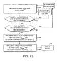
- FIG. 15shows a flow diagram for a method of shield device compensation in accordance with the present invention.
- FIG. 16shows a more detailed flow diagram for the orientation calculation step of FIG. 13 ;
- FIG. 17shows a more detailed flow diagram for the access step of FIG. 13 ;
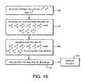
- FIG. 18shows a more detailed flow diagram for the orientation calculation step of FIG. 15 ;
- FIG. 19shows a more detailed flow diagram for the position calculation step of FIG. 15 ;
- FIG. 20Ashows a perspective view of the disposition of the nine coil sets of the examination deck
- FIG. 20Bshows a schematic view of the coil sets of FIG. 20A ;
- FIG. 21Ashows a perspective view of an exemplary disturbance which is in the form of a metallic ring, along with the equivalent circuit model;
- FIG. 21Bshows a perspective view of an elliptical slab of metal including an off center circular hole, along with the equivalent circuit model
- FIG. 21Cshows a perspective view of a solid square metal plate, along with the equivalent circuit model.
- the present inventionis directed to a system and method for determining the position and orientation of a catheter or other suitable probe inserted into a selected body cavity of a patient undergoing a surgical procedure in the presence of field-influencing objects.
- position and orientation datais determined from a series of measurements of voltage amplitudes induced within a sensing coil affixed to the distal end of the catheter probe as a result of the use of multiple waveforms. These voltage amplitudes, as a function of the waveforms, are induced in the sensing coil in response to known independent electromagnetic fields that are projected into the anatomical region of interest.
- the measurementsprovide information to compute the angular orientation and the positional coordinates of the sensing coil and account for the distortion of the known field by arbitrary conductors with field-induced eddy currents.
- position and orientation datais determined from a series of measurements of voltage amplitudes induced within a sensing coil and a tool coil.
- the sensing coilis affixed to the distal end of the catheter probe.
- the tool coilis affixed to a field-influencing object with a ferromagnetic and conducting core.
- the field-influencing objectin the presence of a known electromagnetic field, distorts that field and influences the measurement of the sensing coil.
- the voltage amplitudes from both coilsare stored and can be mathematically manipulated so as to isolate the effect of the field-influencing object on the sensing coil.
- the measurements of the induced voltage amplitudes on the sensing coil and on the tool coilprovide information to account for the presence of the field-influencing object with a ferromagnetic and conductor core.
- the position and orientation datais determined from a series of measurements of voltage amplitudes induced within a sensing coil affixed to the distal end of the catheter probe in the presence of a shield device. These voltage amplitudes are induced in the sensing coil in response to two fields. One of the fields is the known independent electromagnetic field projected into the anatomical region of interest from field coils. The other field is that of the known field as reflected from the shield device.
- the measurements of the induced voltage amplitudes and the knowledge of the geometry and effect of the shield deviceprovide sufficient information to compute the angular orientation and the positional coordinates of this sensing coil in the presence of the shield device.
- sensing coilrefers to an electrically conductive, magnetically sensitive element that is responsive to time-dependent magnetic fields and generates an induced voltage as a function of and representative of the applied time-dependent magnetic field.
- the sensing coilis adaptable for secure engagement to the distal end of a catheter probe.
- tool coilrefers to an electrically conductive, magnetically sensitive element that is responsive to time-dependent magnetic fields and generates an induced voltage as a function of and representative of the applied time-dependent magnetic field.
- the tool coilis adaptable for secure engagement to an object with a ferromagnetic and conducting core.
- navigational domainrefers to a fully enclosed spatial region whose internal volume substantially encloses the complete prospective range of movement of the sensing coil.
- the navigational domainmay be defined by any geometrical space, but preferably takes the form of a spherical volume. Under surgical operating conditions, the navigational domain will correspond to an anatomical region of the recumbent patient where surgical viewing or investigation is desired (e.g., a diseased area of tissue or an organ).
- peripheral domainrefers to the spatial region outside of the navigational domain. Under surgical operating conditions, the peripheral domain may include the region that contains the operating table, or the region that encompasses other equipment within the operating room.
- last navigational pointrefers to the most recently determined location of the sensing coil before another iteration of the location algorithm is performed.
- uniform amplitude fieldrefers to a magnetic field having a large magnetic field amplitude component in a specified direction and relatively smaller magnetic field amplitude components in the other directions.
- the uniform amplitude fieldis characterized by substantially uniform field amplitude values, throughout the navigational domain.
- the amplitudes of the induced voltage drops developed by such fields in the sensing coilare designated with superscripts V x , V Y , and V z , respectively.
- waveformrefers to the temporal shape of a magnetic field, illustrated graphically by a plot of the magnitude of a magnetic field as a function of time.
- a waveform in generalcan take on the characteristics of any form.
- a waveformcan also be sawtooth in nature, or square in nature.
- unidirectional coilsrefer to a magnetic assembly that is operative to generate a uniform amplitude field (as defined above) within the navigational domain. A distinct magnetic assembly is employed for each uniform amplitude field.
- the unidirectional coils described hereinare preferably implemented with a collection of appropriately designed magnetic coils, this implementation should not be construed as a limitation of the present invention. Rather, the unidirectional coils may be constructed from any magnetic configuration that is sufficient to generate the uniform amplitude fields.
- vector gradient fieldrefers to a time-dependent magnetic field having nonzero vector gradient field components (i.e., magnetic field vector components with a high spatial gradient) in two of the three magnetic field components, and a substantially zero vector gradient field component in the remaining magnetic field component in an appropriately chosen coordinate system.
- the appropriately chosen coordinate systemis an x-y-z coordinate system at a position R in the navigational domain
- H n (R)a vector field
- ⁇ ⁇ ⁇( ⁇ ⁇ x , ⁇ ⁇ y , ⁇ ⁇ z )
- a substantially zero vector gradient componentis generated when the magnitude of the substantially zero vector gradient component value is small compared to the magnitude of the net vector resulting from the other two magnetic field components.
- fixed orientationwith respect to a catheter probe refers to a catheter probe with constant values of orientation variables ⁇ and ⁇ , over a selected range of x, y, and z positional values.
- constant signal surfaceor “constant voltage surface” refers to a surface contour along which at every possible point of location for the sensing coil, the same induced voltage is developed in the sensing coil.
- the constant signal surfacewill be a small planar region located near the LNP with the sensing coil at a fixed orientation (as defined above).
- delta coilrefers to a magnetic assembly for generating a vector gradient field (as defined above) within the navigational domain.
- the delta coilwill typically be described in the context of delta coil pairs including a long delta coil and a short delta coil, each pair generating vector gradient fields with the substantially zero component in the same-axial dimension but whose magnetic field patterns in the remaining components are independent of each other.
- Each of the long and short delta coilsmay be considered to generate a family of constant signal or constant voltage surfaces for the sensing coil within the navigational domain.
- delta coilsare preferably implemented with an array of appropriately designed magnetic coils (discussed below), this preferred implementation should not serve as a limitation of the present invention as it should be apparent to those skilled in the art that other magnetic configurations may be used to adequately generate the vector gradient fields.
- magnetic look-up-tablerefers to a database including the magnetic field amplitude values at every x-y-z coordinate position within the navigational domain for the unidirectional coils and for each delta coil used by the present invention. Accordingly, input data consisting of an x-y-z coordinate and a magnetic field amplitude identifier, which designates a selected magnetic coil assembly, is indexed within the database to a corresponding set of magnetic field amplitude values constituting the output data.
- the output datais represented by the magnetic field amplitude variables H x n H y n H z n where the subscript x-y-z indicates the axial dimension along which the magnetic field amplitude value is being reported and the superscript is the identifier for a selected magnetic coil assembly acting as the source.
- the databaseis created through a computational analysis of the magnetic field amplitude patterns generated by the magnetic coil configurations used herein.
- the mathematical model to develop the necessary formulae defining the field patternsmay be developed, for example, from near field electromagnetic theory.
- An instructive text for facilitating such an analysisis “Field and Wave Electromagnetics” 2nd edition Addison Wesley (1989) by D. K. Cheng, herein incorporated by reference.
- the databasemay be stored in any type of facility including, inter alia, read-only memory, firmware, optical storage, or other types of computer storage. Additionally, the database information may be organized into any type of format such as a spreadsheet. It should be apparent to those skilled in the art that any suitable technique may be used to ascertain or record the magnetic field values for the magnetic coil assemblies used herein.
- the z-axiscoincides with the longitudinal dimension extending from the patient's head to foot.
- the x-axiscoincides with a lateral dimension across the patient's body, and the y-axis is perpendicular to the planar top of the pallet or examination deck. These dimensions are identified as the patient is disposed in the recumbent position on the pallet.
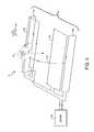
- FIG. 3schematically illustrates a perspective view of examination deck 17 that facilitates implementation of the location and compensation methods in accordance with all preferred embodiments of the present invention.
- Examination deck 17employs a magnetic coil assembly arranged in a flat configuration.
- Examination deck 17includes planar top platform 10 suitable for accommodating a recumbent patient disposed lengthwise.
- Navigational domainis illustratively depicted as the spherical volume enclosing sensing coil 14 .
- Tool coil 19is located in peripheral domain 15 .
- Sensing coil 14is attached via connection means 16 to an external signal detection apparatus (not shown).
- Tool coil 19is likewise attached to an external signal detection apparatus. Although sensing coil 14 functions optimally within navigational domain 12 , tool coil 19 may lie within peripheral domain 15 or navigational domain 12 .
- the coil sets embedded in platform 10are activated by a signal drive unit (not shown) connected via line 18 .
- Examination deck 17is preferably constructed from a suitable magnetically-permeable material to facilitate magnetic coupling between the embedded coil sets and the overlying sensing coil.
- First conducting body 23 and second conducting body 31are shown in FIG. 3 in peripheral domain 15 .
- both first conducting body 23 and second conducting body 31can lie within navigational domain 12 as well in accordance with a preferred embodiment of the present invention.
- First conducting body 23 and second conducting body 31respond to the fields generated by the field coils by developing eddy currents. These eddy currents, in turn, generate new fields that can influence the measured voltage across sensor coil 14 as is discussed in more detail below.
- Ferromagnetic body 29is shown in peripheral domain 15 and is shown enveloped within tool coil 19 . Again, ferromagnetic body 29 and tool coil 19 can lie within navigational domain 12 as well in accordance with a preferred embodiment of the present invention. Ferromagnetic body 29 responds to the fields generated by the field coils by both focusing the magnetic flux lines and by introducing a phase shifted field. The focusing and phase shifting effect of ferromagnetic body 29 can influence the voltage drop as measured across sensor coil 14 as is discussed in more detail below.
- FIGS. 4-6schematically illustrate unidirectional coil sets for generating substantially uniform amplitude x-directed, y-directed and z-directed fields, respectively, throughout navigational domain 12 .
- the uniform amplitude field in one embodiment of the present inventioncan be operated at multiple waveforms, for example, a sinusoidal waveform with angular frequency ⁇ 1 and a sinusoidal waveform with angular frequency ⁇ 2 are two different waveforms.
- Unidirectional coil set 25 of FIG. 4includes a first coil pair with elements 20 and 24 and a second coil pair with elements 22 and 26 , where the current flow as supplied by drive unit 28 is indicated by the arrow symbol.
- Coil elements 20 and 22are disposed in the major surface of platform 10
- elements 24 and 26are disposed in the lateral walls of platform 10 .
- Elements 24 and 26are preferably used as compensation coils to substantially cancel undesirable field components generated by elements 20 and 22 in the y and z directions.
- the coilscumulatively generate a substantially uniform amplitude x-directed field as indicated by representative field line 27 .
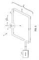
- Unidirectional coil set 35 of FIG. 5schematically illustrates a coil set for generating a substantially uniform amplitude y-directed field throughout navigational domain 12 as indicated by representative field line 33 .
- the coil setincludes a coil pair with elements 30 and 32 disposed in spaced-apart and parallel relationship within platform 10 , with the indicated current flow as supplied by drive unit 34 .
- Unidirectional coil set 45 of FIG. 6generates a substantially uniform amplitude z-directed field as indicated by representative field line 43 .
- Coil set 45includes a first coil pair with elements 38 and 42 and a second coil pair with elements 36 and 40 , where the current flow as supplied by drive unit 44 is indicated by the arrow symbol.
- Coil elements 36 and 38are disposed in the major surface of platform 10
- elements 40 and 42are disposed in the lateral walls of platform 10 .
- Elements 40 and 42are preferably used as compensation coils to substantially cancel undesirable field components generated by elements 36 and 38 in the y direction.
- Unidirectional coil sets 25 , 35 , and 45are illustrative only and should not be construed as a limitation of the present invention. It should be apparent to those skilled in the art that other coil configurations are possible within the scope of the present invention provided such other configurations produce the desired magnetic field patterns in navigational domain 12 at the desired frequency.
- a first connection means(not shown) couples sensing coil 14 to a signal measuring device, and a second connection means (also not shown) couples tool coil 19 to a signal measuring device.
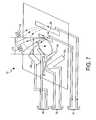
- FIGS. 7 and 8show a coil configuration that can be used to determine the positional coordinates of sensing coil 14 in accordance with all of the preferred embodiments of the present invention.
- the configurationincludes six coils grouped into three pairs of long and short delta coils ( 50 and 52 , 54 and 56 , 58 and 60 ).
- the delta coilsare mutually coplanar and are disposed in the planar top of the examination deck immediately beneath the recumbent patient.
- Interconnection means between delta coil group 51 , delta coil group 55 , delta coil group 59 and a signal drive unit (not shown)is indicated.
- the coilsare preferably arranged in a circular orientation about the y-axis such that there is an axis perpendicular to the direction of elongation of the coils, proceeding from the long coil set to the short coil set, where that axis is at 0°, 120° and 240° to the z-axis.
- the x-axisis considered to be oriented at 270° with respect to the z-axis in the x-z plane.
- the magnetic field generated by delta coil group 51is shown representatively by the field lines extending from the upper region of the coils.
- the resulting vector gradient fieldcan be operated at multiple waveforms.
- a sinusoidal waveform with angular frequency ⁇ 1 and a sinusoidal waveform with angular frequency ⁇ 2are two different waveforms.
- the field lines from delta coil group 51form the family of constant signal surfaces shown in FIG. 8 within the navigational domain 12 .
- Superposition of the constant signal surfaces generated by long coil set 50 and short coil set 52produce the bounded regions indicated in FIG. 8 .
- the intersection of two such constant signal surfaces generated by short coil set 52 and long coil set 50is line 70 .
- FIG. 9shows an upper plan schematic view of delta coil group 51 relative to an inner circular space representing the projection of navigational domain 12 into the plane of the delta coils.
- This designcreates a high spatial gradience in two of the axis dimensions and a substantially zero field value in the remaining axial dimension.
- This particular designis accomplished by modifying the termination points of the coils with compensation coils such that the modified coil is effectively operative as an infinitely long coil.
- Long coil sets 50 , 54 , and 58are further compensated by central “sucker” coils, indicated in FIG. 9 for long coil set 50 as central “sucker” coil 88 .
- each of the long coils and short coilsis modified by representative compensation coils 80 and 82 , 84 and 86 , 88 , 90 and 94 , and 92 and 96 respectively, disposed at the indicated endpoints and center of the corresponding delta coil.
- the long coil and short coil configurationsare shown schematically for only delta coil group 51 , but similar configurations likewise exist for delta coil group 55 and delta coil group 59 , shown representatively as the indicated lines.
- Parameters related to the quality of the coilssuch as (i) the degree of uniformity of the uniform amplitude field coils and (ii) how close to zero the vector gradient field is in the non-gradient direction for the delta coils, determine the size of navigational domain 12 and peripheral domain 15 .
- FIG. 10indicates tool coil 19 affixed to surgical tool 108 , where surgical tool 108 is a ferromagnetic and conducting object. Also shown is exemplary hysteresis graph 100 of surgical tool 108 .
- Hysteresis graph 100illustrates the nonlinear behavior of a magnetic field H associated with surgical tool 108 in response to an applied magnetic field B. Such a response is typical of ferromagnetic objects.
- FIG. 11indicates how surgical tool 108 and tool coil 19 of FIG. 10 may be used in practice.
- Surgical tool 108is used to drill holes into vertebrae 110 .
- FIG. 12schematically illustrates a perspective view of examination deck 17 that facilitates implementation of the location and compensation algorithms in accordance with shield device 120 .
- Examination deck 17includes planar top platform 10 suitable for accommodating a recumbent patient disposed lengthwise. Examination deck 17 rests on base 122 .
- Navigational domain 12is illustratively depicted as the spherical volume enclosing a sensing coil 14 attached via connection means 16 to an external signal detection apparatus (not shown).
- the coil sets embedded in platform 10(and described in connection with FIGS. 4-7 ) are activated by a signal drive unit (not shown) connected via line 18 .
- the examination deckis preferably constructed from a suitable magnetically permeable material to facilitate magnetic coupling between the embedded coil sets and the overlying sensing coil.
- Shield device 120can be made from aluminum, copper or virtually any other conductive material. It is also possible to use materials other than a conductive sheet such as a mesh or strips of material. A further possibility is to use a plastic of poly
- FIG. 13indicates a schematic of a method for eddy current compensation consistent with the present invention.
- Measuring steps 132 and 134involve activating each of nine coil sets and measuring the field at sensing coil 14 at different waveforms. For example, a sinusoidal waveform with angular frequency ⁇ 1 and a sinusoidal waveform with angular frequency ⁇ 2 correspond to two different waveforms.
- the nine coil setscorrespond to three unidirectional coil sets and three delta coil groups, where each delta coil group contains a long coil set and a short coil set.
- the unidirectional coil sets-generate uniform amplitude fields in the x, y, and z-directions and are depicted in FIGS. 4 , 5 , and 6 . From FIG.
- the angular designations associated with the delta coil groupsindicate the angle with respect to the z-axis of the coil dimension that is perpendicular to the direction of elongation of the delta coils as in FIG. 7 . Accordingly, the three delta coil groups are arranged pair-wise in a circular orientation about the y-axis at angles of 0°, 120°, and 240°.
- a series of fieldsare generated and measured in sensing coil 14 at a first waveform (measuring step 132 ) and at an mth waveform (measuring step 134 ).
- the waveformscorrespond to substantially uniform amplitude fields with sinusoidal waveforms and angular frequencies ⁇ 1 and ⁇ 2
- the value of a constant ⁇ eddydefined by:
- ⁇ eddyRe ⁇ ⁇ V x ⁇ ( ⁇ 2 ) ⁇ 2 - V x ⁇ ( ⁇ 1 ) ⁇ 1 ⁇ Im ⁇ ⁇ V x ⁇ ( ⁇ 1 ) - V x ⁇ ( ⁇ 2 ) ⁇
- measurementsare performed at four different waveforms (measuring steps 132 and 134 in FIG. 13 ).
- a magnetic field waveformthat is sinusoidal in nature with angular frequency ⁇
- measurements at four frequencies ⁇ 1 , ⁇ 2 , ⁇ 3 , and ⁇ 4correspond to measuring steps 132 and 134 at four different waveforms.
- step 140it is determined whether all unidirectional field coils have been activated. In the example here, only the x-directed coils have been activated (coil set 25 of FIG. 4 ). Thus, a corresponding set of substantially uniform amplitude fields with different waveforms are generated and measured at sensing coil 14 in the y-direction by coil set 35 of FIG. 5 , and then likewise in the z-direction by coil set 45 of FIG. 6 , with the appropriate calculations.
- each delta coil setis activated in succession the induced voltage is measured in sensing coil 14 at different waveforms. Again as above, the measurement of the voltage drops at the two waveforms allow for the calculation of an adjusted voltage drop across sensing coil 14 .
- V adjstis the signal that would have been picked up by sensor coil 14 if the conductive body disturbance had not been present.
- step 144an orientation calculation is performed in step 144 to determine the values of the sensing coil 14 orientation variables ⁇ and ⁇ , independent of the unknown sensing coil 14 positional variables (x,y,z).
- orientation calculation 144is shown in FIG. 16 and is discussed in more detail below.
- step 146 of FIG. 13a position calculation is performed to obtain the positional variables (x,y,z) of sensing coil 14 .
- FIG. 17A more detailed breakdown of position calculation 146 is shown in FIG. 17 .
- access step 176indicates that orientation calculation 144 is preferably performed before positional calculation 146 .
- access step 178the LUT is accessed to obtain the magnetic field values at the LNP for a long delta coil set and a short delta coil set. These magnetic field values and the as-computed values for the orientation angles ⁇ and ⁇ are substituted into the appropriate induced voltage equations to calculate for each delta coil the value of the voltage amplitude signal induced in the sensing coil at the LNP.
- step 180Based on the difference between the measured and the LNP values for the induced voltage signals, a calculation is performed in step 180 that permits identification of a line I n on which sensing coil 14 lies, as described in more detail below.
- query step 182it is determined whether such a line I n has been identified for each delta coil group.
- step 184is performed to determine where in space the lines I 1 ,I 2 ,I 3 intersect. That position in space is the location (x,y,z) of sensing coil 14 .
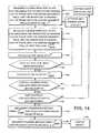
- FIG. 14indicates a schematic for ferromagnetic and conductor compensation consistent with the present invention.
- Measuring step 152is similar to measuring step 132 as described above for FIG. 13 .
- Measuring step 154is different, however, in that a measurement is performed across tool coil 19 .
- the nine coil setscorrespond to three unidirectional coil sets and three delta coil groups, where each delta coil group contains a long coil set and a short coil set.
- the unidirectional coil setsgenerate uniform amplitude fields in the x, y, and z-directions and are depicted in FIGS. 4 , 5 , and 6 .
- the delta coil setsare depicted in FIG. 7 and described above.
- sensing coil 14(measuring step 152 ) and tool coil 19 (measuring step 154 ) originating from unidirectional coil set 25 of FIG. 4 , unidirectional coil set 35 of FIG. 5 , and unidirectional coil set 45 of FIG. 6 .
- each delta coilis activated in succession and a corresponding induced voltage is measured in sensing coil 14 (measuring step 152 ) and tool coil 19 (measuring step 154 ).
- step 160 of FIG. 14This is step 160 of FIG. 14 and is described in more detail below.
- FIG. 15indicates a schematic of a method for shield device compensation consistent with the present invention.
- a magnetic assembly of nine individual coil sets and shield device 120are used to generate magnetic fields sufficient to develop a corresponding set of nine induced voltage signals at sensing coil 14 .
- Measurement step 162indicates such a measurement.
- the major difference associated with shield device compensationis observed in calculation steps 164 and 166 .
- orientation calculation step 164 of FIG. 15is shown in more detail in FIG. 18 .
- position calculation step 166 of FIG. 15is shown in more detail in FIG.
- an additional manipulation step 188is incorporated as compared to the schematic of FIG. 16 .
- an additional manipulation step 192is incorporated, as compared to the schematic of FIG. 17 .
- the additional manipulation step associated with the shield device compensation methodinvolves the manipulation of the values of the LUT. Specifically, knowledge of the geometry of the coil sets and shield device 120 is sufficient to allow manipulation of the LUT in order to account for the effect of shield device 120 within navigational domain 12 . The effects of arbitrary field-influencing objects that lie in peripheral domain 15 and anterior to shield device 120 are thereby cancelled.
- the input data for the LUTconsists of the x-y-z coordinates and a designation of which coil set is being used to generate the magnetic fields (the superscript “n”).
- the LUTsupplies the magnetic field amplitude values H x n (R),H y n (R), and H z n (R) at the selected x-y-z coordinates for the designated coil set. Note that in the previously discussed preferred embodiments of the present invention, the LUT can only be successfully utilized after compensation for field-influencing objects has occurred. However, in the preferred embodiment of the present invention, compensation for shield device 120 may be incorporated into the LUT.
- the LUTis present to speed up the operational sequence of the location algorithm. Otherwise, an undesirable computational delay exists if the required magnetic fields from the nine coil sets must be individually calculated during each iteration of the algorithm.
- the location algorithmneed only access the LUT to retrieve the appropriate field value without endeavoring into any complex field analysis. This is especially true when shield device compensation is an issue.
- an interpolation procedureis employed to calculate the field value.
- the system and method used hereinis directed to the development of a series of measurements and calculations able to account for the effects of a field-influencing object that would otherwise introduce error into a position and orientation determination.
- the relationships defined by these systems and methodsare such that the unknown effects of the field-influencing object are separable.
- the angular orientation of sensor coil 14is represented by an angle ⁇ corresponding to the angle of departure from the z-axis and an angle ⁇ corresponding to the angle between the x-axis and the projection onto the x-y plane of the vector coincident with the longitudinal axis of sensing coil 14 as shown in FIG. 2 .
- the unidirectional coilsare activated in succession, each generating a substantially uniform amplitude field that projects into navigational domain 12 and induces a corresponding voltage signal in sensing coil 14 .
- the LUTis then accessed three times to acquire the magnetic field values at the LNP for each of the three unidirectional coils.
- these values and the measured voltage signalsare then substituted into the appropriate equations set forth below to solve for the unknown variables ⁇ and ⁇ that define the orientation of sensing coil 14 .
- the time-dependent magnetic fields projected into the navigational domaininduce voltages in sensor coil 14 that are representative of the orientation of coil axis a 21 relative to the lines of magnetic flux.
- the development of an induced voltage in sensing coil 14 in response to a changing magnetic fieldis defined by Faraday's law.
- the induced voltage as a function of time V(t) around this pathis equal to the, negative time rate of change of the total magnetic flux through the closed path (one turn).
- the magnetic flux ⁇ through Sis given by,
- ⁇ nN ⁇ ⁇ S ⁇ ⁇ 0 ⁇ H n ⁇ ( t ) ⁇ a ⁇ ⁇ d a
- V n ⁇ ( t )- d d t ⁇ ⁇ n
- neither the surface S, or the closed path C determined by the position of sensing coil 14are a function of time.
- V n ⁇ ( t )- N ⁇ ⁇ S ⁇ ⁇ 0 ⁇ ⁇ H n ⁇ ( t ) ⁇ t ⁇ a ⁇ ⁇ d a
- the induced voltage amplitude V n in sensing coil 14will vary with changes in the angular orientation between the coil axis and the direction of the magnetic field lines ⁇ .
- a useful reference frame for spatially conceptualizing the interaction between sensing coil 14 and the magnetic fields in navigational domain 12is the Cartesian coordinate system defined by mutually perpendicular axes x-y-z. As above, coil axis 21 is through sensing coil 14 .
- angles ⁇ , ⁇ , ⁇ that the coil axis 21 makes with the unit coordinate vectors x, y, and z respectively,are called the direction angles of coil axis 21 ; the trigonometric terms cos( ⁇ ),cos( ⁇ ) and cos( ⁇ ) represent direction cosine values.
- V x⁇ H x x sin( ⁇ )cos( ⁇ )+ ⁇ H y x sin( ⁇ )sin( ⁇ )+ ⁇ H z x cos( ⁇ )
- the terms H x y and H z y in the equation for V y and the terms H x z and H y z in the equation for V zare small compared to H y y and H z z respectively.
- the linearly independent equationsare simultaneously solved to determine the unknown variables ⁇ and ⁇ defining the orientation of coil axis 21 . This corresponds to calculation step 172 of FIG. 16 .
- the last navigation pointrefers to the x-y-z positional coordinates of sensing coil 14 as determined by the immediately previous computation cycle.
- the LNPis the center of the viewing field.
- This sectiondescribes in more detail the eddy current compensation method as indicated by the schematic of FIG. 13 .
- extraneous conducting object 23may be present either in navigational domain 12 or peripheral domain 15 that responds to the fields generated for measurement purposes.
- FIG. 20Ashows the disposition of the nine coil sets of the examination deck 17 ; the coil sets are also shown in FIG. 20B where they are schematically represented as 1-9.
- first conducting object 23it is subjected to a field H 1 (R d ) which is the field produced by coil set # 1 at the location of first conducting object 23 .
- H 1 (R d )is the field produced by coil set # 1 at the location of first conducting object 23 .
- This fieldwill induce eddy currents ID that flow in first conducting object 23 and these currents will produce disturbing magnetic fields of their own, these are designated H D 1 (x,y,z).
- H D 1 (x,y,z)the desired field upon which navigation is calculated
- H D 1 (X,Y,Z) the disturbancethe signal produced in sensing coil 14 also has two components corresponding to the two fields. In order to isolate and separate these, one must understand the characteristics of eddy currents produced in first conducting object 23 of arbitrary shape and characteristics.
- FIG. 21Adepicts an exemplary disturbance in the form of a metallic ring.
- This ringwill have an inductance L and a resistance R that depend on the dimensions and materials of the ring.
- FIG. 21Bshows an elliptical slab of metal with an off center circular hole cut in it. The eddy current performance of this shape is largely described by three current loops or modes of excitation. These are numbered 1, 2, 3, each of these modes has its' own L, R and ⁇ and its own degree of interaction to an incoming field.
- the eddy current equivalentis therefore a summation of three circuits each similar to that for the case shown in FIG. 21A .
- a similar analysisprevails in the case shown in FIG. 21C , which corresponds to a solid square plate.
- FIG. 21Cwhich corresponds to a solid square plate.
- # 1a dominant mode which corresponds to the current circulation around the largest dimensions of the disturbing shape, this gives the largest interaction with the incoming field and also produce the largest field generation.
- any shape disturbancecan always be described as an infinite summation of simple LR circuits.
- the first objective in the following descriptionis to show how the dominant mode of any disturbance 23 can be eliminated in its effect of the signal V N (t) and therefore eliminate its effect on navigation.
- the second objectiveis to show how higher order modes can be eliminated.
- the induced voltage at the sensing coil 14has two components, the direct coupling from the transmitter coils and the indirect coupling from the first conducting object 23 , which gives
- V n ⁇ ( t )⁇ ⁇ ⁇ exp ⁇ ( - i ⁇ ⁇ ⁇ t - i ⁇ / 2 ) ⁇ ⁇ 0 n + ⁇ 2 ⁇ exp ⁇ ( - i ⁇ ⁇ ⁇ t - i ⁇ ) ⁇ ⁇ eddy n ⁇ L eddy R eddy - i ⁇ ⁇ ⁇ L eddy
- V n⁇ 0 n - i ⁇ 2 ⁇ ⁇ eddy n ⁇ L eddy R eddy - i ⁇ ⁇ ⁇ L eddy
- V n ⁇⁇ 0 n - ⁇ eddy n ⁇ i ⁇ eddy 1 - i ⁇ eddy
- V n ⁇⁇ 0 n + ⁇ eddy n ⁇ ⁇ 2 ⁇ ⁇ eddy 2 1 + ⁇ 2 ⁇ ⁇ eddy 2 - i ⁇ eddy n ⁇ ⁇ eddy 1 + ⁇ 2 ⁇ ⁇ eddy 2
- V n ⁇⁇ 0 n + ⁇ eddy n ⁇ ⁇ 2 ⁇ ⁇ eddy 2 1 + ⁇ 2 ⁇ ⁇ eddy 2 + exp ⁇ ( - i ⁇ / 2 ) ⁇ ⁇ eddy n ⁇ ⁇ eddy 1 + ⁇ 2 ⁇ ⁇ eddy 2
- first conducting object 23has altered the magnitude of the measured voltage amplitude due to the source coils, at the expected phase shifted point exp( ⁇ i ⁇ t ⁇ i ⁇ /2), by an amount ⁇ V n ⁇ eddy equal to
- ⁇ ⁇ ⁇ V n - eddy⁇ eddy n ⁇ ⁇ 3 ⁇ ⁇ eddy 2 1 + ⁇ 2 ⁇ ⁇ eddy 2
- V ⁇ / 2 n - eddy⁇ eddy n ⁇ ⁇ 2 ⁇ ⁇ eddy 1 + ⁇ 2 ⁇ ⁇ eddy 2
- V adjst n⁇ 0 n .
- V ⁇ /2 n ⁇ eddyThe value of the amplitude V ⁇ /2 n ⁇ eddy can be obtained directly by measurement, since it lags the expected voltage drop signal by the additional phase of ⁇ /2 radians, or 90°. Thus, only ⁇ eddy need be determined in order to compensate for an extraneous eddy current.
- a second linearly independent equationis obtained by taking a voltage amplitude measurement using a second magnetic field waveform, for example, taking a voltage amplitude measurement at a second angular frequency.
- V n ( ⁇ 2 )⁇ 1 ⁇ 0 n + ⁇ 1 ⁇ eddy V ⁇ /2 n ⁇ eddy ( ⁇ 1 ) ⁇ iV ⁇ /2 n ⁇ eddy ( ⁇ 1 )
- V n ( ⁇ 2 )⁇ 2 ⁇ 0 n + ⁇ 2 ⁇ eddy V ⁇ /2 n ⁇ eddy ( ⁇ 2 ) ⁇ iV ⁇ /2 n ⁇ eddy ( ⁇ 2 )
- ⁇ eddyRe ⁇ ⁇ V n ⁇ ( ⁇ 2 ) ⁇ 2 - V n ⁇ ( ⁇ 1 ) ⁇ 1 ⁇ Im ⁇ ⁇ V n ⁇ ( ⁇ 1 ) - V n ⁇ ( ⁇ 2 ) ⁇
- V n ⁇⁇ 0 n + ⁇ 1 n ⁇ ⁇ 2 ⁇ ⁇ 1 2 1 + ⁇ 2 ⁇ ⁇ 1 2 - i ⁇ 1 n ⁇ ⁇ 1 1 + ⁇ 2 ⁇ ⁇ 1 2 ++ ⁇ ⁇ 2 n ⁇ ⁇ 2 ⁇ ⁇ 2 2 1 + ⁇ 2 ⁇ ⁇ 2 2 - i ⁇ 2 n ⁇ ⁇ 2 1 + ⁇ 2 ⁇ ⁇ 2 2
- V n ⁇ ( ⁇ ) ⁇⁇ 0 n + ⁇ 1 n ⁇ ⁇ 2 ⁇ ⁇ 1 2 1 + ⁇ 2 ⁇ ⁇ 1 2 - i ⁇ 1 n ⁇ ⁇ 1 1 + ⁇ 2 ⁇ ⁇ 1 2 ++ ⁇ ⁇ 2 n ⁇ ⁇ 2 ⁇ ⁇ 2 2 1 + ⁇ 2 ⁇ ⁇ 2 2 - i ⁇ 2 n ⁇ ⁇ 2 1 + ⁇ 2 ⁇ ⁇ 2 2
- f 1 ( ⁇ 1 , ⁇ 2 , ⁇ 1 , ⁇ 2 ), and f 2 ( ⁇ 1 , ⁇ 2 , ⁇ 1 , ⁇ 2 )are polynomial functions of ⁇ 1 , ⁇ 2 , ⁇ 1 , and ⁇ 2 .
- the solution to the above equationsyields the adjusted value of the potential drop measurement and corresponds to calculation step 138 of FIG. 13 in one embodiment of the present invention.
- the general resultis that resolving in values of ⁇ m , requires m measurements of real and imaginary parts of the potential drop across sensing coil 14 , using m different waveforms. For example, measurements of a sinusoidal waveform at the set of frequencies ( ⁇ 1 , ⁇ 2 , . . . ⁇ m ) are sufficient to resolve m values of ⁇ m . Since each additional conducting body introduces a new variable ⁇ m and an associated coupling constant ⁇ m n , each additional conducting body introduces two new unknowns. However, a measurement of a potential drop across sensing coil 14 at a new waveform m, including both the real and imaginary portions, yields the required number of two new equations necessary to resolve ⁇ m and ⁇ m n .
- V n ⁇V n ⁇ 1 + ⁇ ⁇ ⁇ ⁇ ( V n ⁇ 1 ) ⁇ ( ⁇ - ⁇ 1 ) + 1 2 ⁇ ⁇ 2 ⁇ ⁇ 2 ⁇ ( V n ⁇ 1 ) ⁇ ( ⁇ - ⁇ 1 ) 2 + R 3
- V n ⁇⁇ 0 n + ⁇ 1 n ⁇ ⁇ 2 ⁇ ⁇ 1 2 1 + ⁇ 2 ⁇ ⁇ 1 2 - i ⁇ ⁇ ⁇ 1 n ⁇ ⁇ ⁇ ⁇ ⁇ 1 1 + ⁇ 2 ⁇ ⁇ 1 2 + ⁇ 2 n ⁇ ⁇ 2 ⁇ ⁇ 2 2 1 + ⁇ 2 ⁇ ⁇ 2 2 - i ⁇ ⁇ ⁇ 2 n ⁇ ⁇ ⁇ ⁇ 2 1 + ⁇ 2 ⁇ ⁇ 2 2 2
- V adjst nV n - ⁇ ⁇ ⁇ ⁇ ( V n ⁇ 1 ) ⁇ ⁇ 1 2 + 1 2 ⁇ ⁇ 2 ⁇ ⁇ 2 ⁇ ( V n ⁇ 1 ) ⁇ ⁇ 1 2 + R 3
- V n ⁇⁇ 0 n + ⁇ eddy n ⁇ ⁇ 2 ⁇ ⁇ eddy 2 1 + ⁇ 2 ⁇ ⁇ eddy 2 - i ⁇ ⁇ ⁇ eddy n ⁇ ⁇ eddy 1 + ⁇ 2 ⁇ ⁇ eddy 2
- This sectiondescribes in more detail the ferromagnetic and conductive object compensation method as indicated by the schematic of FIG. 14 .
- a pure magnetic coreis a source of magnetic flux.
- the primary quality of a pure magnetic coreis that it can enhance, or focus, magnetic field flux lines along a preferred direction.
- V n ⁇ ( t )- ⁇ S ⁇ ⁇ ⁇ ⁇ H n ⁇ ( t ) ⁇ ⁇ ⁇ a ⁇ ⁇ d a
- V magn n ⁇ ( t )- T ⁇ ⁇ S magn ⁇ ⁇ ⁇ H n ⁇ ( t ) ⁇ ⁇ ⁇ a magn ⁇ ⁇ d a magn
- Surgical tool 108 of FIG. 10has some qualities of a pure magnetic object, as well as additional properties. Like a pure magnetic object, it can act to enhance the detection of flux lines through the center of tool coil 19 as above. However, it also responds to an applied field in a nonlinear manner, as is indicated on hysteresis graph 100 . Furthermore, the additional presence of conductive elements introduce additional fields that are out of phase by ⁇ /2 with any enhanced field in the vicinity. Thus, a general form for the voltage drop across tool coil 19 affixed around surgical tool 108 :
- V ferro n ⁇ ( t )- ( T Re - i ⁇ ⁇ T Im ) ⁇ ⁇ S ferro ⁇ ⁇ ⁇ ⁇ H n ⁇ ( t ) ⁇ ⁇ ⁇ a ferro ⁇ d a ferro
- V ferro n ⁇ ( t )- ( T Re - i ⁇ ⁇ T lm ) ⁇ ⁇ S ferro ⁇ ⁇ ⁇ ⁇ H n ⁇ ( t ) ⁇ ⁇ ⁇ a ferro ⁇ d a ferro
- V n ( t )⁇ exp( ⁇ i ⁇ t ⁇ i ⁇ / 2) ⁇ 0 n + ⁇ exp( ⁇ i ⁇ t ⁇ i ⁇ / 2)( T Re ⁇ iT Im ) ⁇ ferro n
- V n⁇ 0 n + ⁇ ferro n ( T Re ⁇ iT Im )
- V ferro n⁇ ferro n ( T Re ⁇ iT Im )
- This sectiondescribes in more detail the shield device compensation method as indicated by the schematics of FIGS. 15 , 18 , and 19 .
- disturbancescan include the operating table, a head-holder or other any number of other metallic items.
- any field-influencing effect of an operating room tablehas the potential to create a larger than typical distortion in the fields located in the navigational domain.
- shield device 120is provided to restrict the propagation of magnetic fields through it, as, for example, a sheet of conductive material. It may be arranged in any suitable geometry that has a fixed relationship to the transmission coils. There are many possible materials that the plate can be made from, such as aluminum, copper or virtually any other conductive material. It is also possible to use materials other than a conductive sheet such as a mesh or strips of material. A further possibility is a plastic of polymer film with a conductive coating.
- Shield device 120should preferably be placed between the transmitter coil array and the disturbance. In an operating room, if the patient were to lay on the transmitter coil array, then shield device 120 could be placed under the array to block effects of the operating table. An additional enhancement could be made by bending the sides of shield device 120 up at an angle to negate the effects of the length of the operating table. Other arrangements for shield device 120 are possible, such as placing it to block the effects of microscopes or C-arms that may be present in the field.
- the devicealters the fields produced by the transmitter coils.
- the effect of the devicecan either be computed from electromagnetic theory, as for example, from “Static and Dynamic Electricity” third edition, Taylor & Francis (1989) by William R. Smythe.
- the effectcould also be measured in a calibration process. Both of these techniques correspond to steps 188 and 192 of FIGS. 18 and 19 respectively.
- a fixed geometrycan be characterized by a fixed alteration of the transmitted field. If the device is to be moved, a dynamic correction of the effect should be performed.
- step 144 in FIGS. 13 and 14was indicated as occurring after all of the coil sets were activated and measured.
- Step 144can be placed after step 140 in both FIGS. 13 and 14 and is consistent with the present invention.
- the magnetic fieldwas considered to have a sinusoidal waveform at an angular frequency ⁇ , but other examples of waveforms are possible consistent with an embodiment of the present invention, including sawtooth waves, or square waves.
- waveformsincluding sawtooth waves, or square waves.
- any numerical technique for solving an overspecified equationis consistent with the present invention.
Landscapes
- Health & Medical Sciences (AREA)
- Surgery (AREA)
- Life Sciences & Earth Sciences (AREA)
- Engineering & Computer Science (AREA)
- Medical Informatics (AREA)
- General Health & Medical Sciences (AREA)
- Biomedical Technology (AREA)
- Heart & Thoracic Surgery (AREA)
- Nuclear Medicine, Radiotherapy & Molecular Imaging (AREA)
- Molecular Biology (AREA)
- Animal Behavior & Ethology (AREA)
- Veterinary Medicine (AREA)
- Public Health (AREA)
- Robotics (AREA)
- Oral & Maxillofacial Surgery (AREA)
- Pathology (AREA)
- Measurement Of Length, Angles, Or The Like Using Electric Or Magnetic Means (AREA)
- Magnetic Resonance Imaging Apparatus (AREA)
Abstract
Description
Hn(R)=(Hxn(R),Hyn(R),Hzn(R))
- where the components Hxn(R), Hyn(R), and Hzn(R) represent the magnetic field amplitude strengths of the nth coil (designated by the superscript “n”) in the x-direction, y-direction, and z-direction, respectively and are individually scalar quantities. The value of a vector gradient of such a magnetic field amplitude Hn(R) where the magnetic field has a substantially zero vector gradient component in the z-direction can be written as the following vector gradient (or tensor) field:
{right arrow over (∇)}Hn(R)=({right arrow over (∇)}Hxn(R),{right arrow over (∇)}Hyn(R),0), where
{right arrow over (∇)}Hxn(R)≠0, and
{right arrow over (∇)}Hyn(R)≠0 - and where the gradient operator {right arrow over (∇)} has the usual representation in x-y-z coordinates:
- is calculated where “Re” indicates the real part (0 radians phase shifted part), and “Im” indicates the imaginary part (π/2 radians phase shifted part) of the terms enclosed in the brackets. This corresponds to a portion of
calculation step 138 of FIG.13 in one embodiment of the present invention and will be discussed in more detail below.
Vadjstx=Re{Vx}+ωτeddyIm{Vx}.
Re{Vn}=Vadjustn−ωIm{Vn}(τ*+ωτ**)
- with three unknowns: τ*, τ**, and Vadjustn. Thus, the value of Vadjustncan be determined using singular value decomposition as is described in more detail below. Again, this corresponds to
calculation step 138 inFIG. 13 in one embodiment of the present invention.
Im{Vn−KVferron}=0
- where “Im” indicates the imaginary part (π/2 radians phase shifted part) as above. In
calculation step 160, the value of Vadjstnis calculated using K
Vadjstn=Vn−KVferron
- where μ0is the magnetic permeability of free space and is a constant, the superscript “n” simply associates a given flux ωnwith a given field Hn(t), â is a vector normal to surface S, and da is a differential unit of area, and N is the number of turns in the
coil 14. The mathematical statement of Faraday's law is, thus,
- where Hn=|Hn|. This assumes that each turn of the coil is separately and equally linked by the magnetic flux (e.g., in tightly wound coils), the induced voltage within sensing
coil 14 may be approximated as the summation of the induced voltages developed in each turn.
Vn(t)=−Nωπr2μ0Hncos(ρ)exp(−iωt−iπ/2)
Vn(t)=Vnexp(−iωt−iπ/2). Thus
Vn(t)=−Nωπr2μ0Hncos(ρ)
â·x=cos(α)=sin(φ)cos(θ)
â·y=cos(β)=sin(φ)sin(θ), and
â·z=cos(γ)=cos(φ)
Vx=κωHxxsin(φ)cos(θ)+κωHyxsin(θ)sin(φ)+κωHzxcos(φ)
- where κ=−Nπr2μ0and is independent of frequency. The subscripts in the field intensity amplitudes indicate the axial dimension along which the magnetic field amplitude value was determined by accessing the LUT for the given coil set at the LNP, while the superscript in the voltage amplitude and the field intensity terms indicates the field-generating coil set: in this case the x-directed uniform amplitude field. For an x-directed substantially uniform field, the terms Hyxand Hzxare small compared to Hxx. Similar equations are developed below for the induced voltages produced by the unidirectional coils successively generating a y-directed and z-directed substantially uniform field:
Vy=κωHxysin(φ)cos(θ)+κωHyysin(φ)sin(θ)+κωHzycos(φ), and
Vz=κωHxzsin(φ)cos(θ)+κωHyzsin(φ)sin(θ)+κωHzzcos(φ)
ΔVnexp(−iωt−iπ/2)=−Nωr2μ0ΔR·{right arrow over (∇)}(H0n·â)exp(−iωt−iπ/2)
ΔVn=κωΔR·{right arrow over (∇)}(H0n·â)
R=(x,y,z):
- which has the general form
Axnx+Ayny+Aznz=Bn - where the variables Ajnand and Bnare constants. Such an equation in general determines a plane in three dimensions. Since it is assumed that the displacement vector ΔR is small, then, for a small region around the LNP R0=(x0,y0,z0), a small planar portion of the constant signal surface associated with a delta coil and a given
sensing coil 14 orientation can be identified.
- provided that {right arrow over (∇)}(H0n(s)·â)≠0 or {right arrow over (∇)}(H0n(L)·â)≠0. Each equation independently determines a small planar region of a constant signal surface, and the simultaneous solution of both of the equations determines a line ℑnin three dimensional space on which the unknown point R=(x,y,z) lies. This corresponds to
calculation step 180 ofFIG. 17 . In practice, the delta coil pairs are constructed so that the substantially zero gradient component of both the short coil and the long coil field are in the same direction. Denoting such a direction by cn, this implies by definition that
{right arrow over (∇)}(H0n(s)·cn)=0, and
{right arrow over (∇)}(H0n(L)·cn)=0
{right arrow over (∇)}(H0n(s)·â)=0, and
{right arrow over (∇)}(H0n(L)·â)=0
- where the coupling variables η0nand ηeddynare incorporated to indicate the coupling with the source field and the resulting eddy field respectively. Factoring out the time dependence and the phase factor π/2 as before, where,
Vn(t)=Vnexp(−iωt−iπ/2), the following result is obtained: ps
- If the variable τeddyis defined as:
- Then the above equation can be rewritten as:
- This equation can be rewritten in terms of real and imaginary parts:
- ΔVη−eddycontains the two unknowns τeddyand ηn
eddy . An additional voltage signal is phase shifted by a further π/2 radians with an amplitude Vπ/2n−eddy:
- The measured voltage drop Vncan be rewritten as:
Vn=ωη0n+ωτeddyVπ/2n−eddy−iVπ/2n−eddy
Vn(ω2)=ω1η0n+ω1τeddyVπ/2n−eddy(ω1)−iVπ/2n−eddy(ω1)
Vn(ω2)=ω2η0n+ω2τeddyVπ/2n−eddy(ω2)−iVπ/2n−eddy(ω2)
- where “Re” denotes the real part of the enclosed quantity. Meanwhile, the difference of the amplitudes between the two frequencies with the time dependence and phase that goes as exp(−iωτ−iπ) can be written as:
Im{Vn(ω1)−Vn(ω2)}={Vπ/2n−eddy(ω2)−Vπ/2n−eddy(ω1)} - where “Im” denotes the imaginary part of the enclosed quantity. Thus:
Vadjstn=ωη0n=Re{Vn}+ωτeddyIm{Vn}
- where η1nand τ1correspond to first conducting
object 23 and η2nand τ2correspond to second conducting object31. Thus, for a given real and imaginary measurement of Vnacross sensingcoil 14, there are 5 unknowns η0n, η1n, η2n, η1n, τ1, and τ2. By equating the real and imaginary portions of the measurements across sensingcoil 14 with the real and imaginary portions of the above equations, there are two linearly independent equations. thus, there are an insufficient number of equations to determine all five of the unknowns η0n, η1n, η2n, η1n, τ1, and τ2.
- where ω is selected from the set ω=(ω1,ω2,ω3). In the above equations, the unknowns η1nand η2nappear as linear coefficients. Therefore, by subtracting a measurement of
- taken by sensing
coil 14 from a measurement of
- the above equations can be rewritten in the general form
η1n=f1(ω1,ω2,τ1,τ2), and
η2n=f2(ω1,ω2,τ1,τ2)
- taken by sensing
coil 14 from a measurement of
- the above equations can also be rewritten in the general form
η1n=g1(ω1,ω3,τ1,τ2), and
η2n=g2(ω1,ω3,τ1,τ2) - where again g1(ω1,ω3,τ1,τ2) and g2(ω1,ω3,τ1,τ2) are polynomial functions of ω1,ω3,τ1, and τ2. Therefore, the following polymial equations provide two equations with two unknowns:
g1(ω1,ω3,τ1,τ2)=f1(ω1,ω3,τ1,τ2), and
g2(ω1,ω3,τ1,τ2)=f2(ω1,ω3,τ1,τ2).
- where R3indicates that the neglected terms are of the third order in the derivative of
- denotes a first derivative of the function
- with respect to ω evaluated at ω=ω1, and
- denotes a second derivative of the function
- with respect to ω evaluated at ω=ω1.
- the term η0nis the only variable that appears without any associated factors of ω. Thus, collecting similar powers of ω yields the relationship:
- The quantity Vnis measured at sensing
coil 14 at a frequency ω1while the quantity
- can be determined from measurements at sensing
coil 14 at any two of three frequencies ω1,ω2, and ω3, or using all three frequencies ω1,ω2, and ω3. In addition, the quantity:
- can be determined from measurements at sensing
coil 14 at three frequencies ω1,ω2, and ω3. Thus, using measurements at sensingcoil 14 at three frequencies ω1,ω2, and ω3, the adjusted value for the potential drop across sensingcoil 14 can be determined according to:
- for the situation where there are multiple conducting objects that induce eddy currents and when there are multiple values of τm.
Vadjstn=ωη0n=Re{Vn}+ωτeddyIm{Vn}
- this equation can be rewritten:
Re{Vn}=Vadjstn−ωτ*Im{Vn} - where Re{Vn} is determined from a measurement across
sensing coil 14, Im{Vn} is also determined from a measurement acrosssensing coil 14, ω1is known and both τ* and Vadjstnare unknown. The notation τ* is used here merely to indicate a composite τeddythat may be a result from several conducting objects. from the general relationship derived above
- the next higher order correction appears as to a composite τ* can be written as:
Re{Vn}=Vadjstn−ωIm{Vn}(τ*+ωτ**) - where the notation τ** indicates that it is a correction to the term τ* appearing as a coefficient to ω. the units of τ** correspond to the units of (τ*)2.
Re{Vn}=Vadjstn−ωIm{Vn}(τ*+ωτ**)
- with three unknowns τ*, τ**, and Vadjstn, is sufficient to determine Vadjstnwith the desired precision. Specifically, the above four equations with three unknowns is solved using singular value decomposition, as described, for example, in Numerical Recipes, Cambridge (1986), by W.H. press, B. P. Flannery, S. A. Teukolsky, and W. T. Vetterling. This, again, corresponds to
calculation step 138 ofFIG. 13 .
- where the quantity on the right is proportional to the time rate of change of magnetic flux, it can be seen that, as a source of flux lines, a pure magnetic object will act to enhance the voltage drop. Thus, for a pure magnetic object with
tool coil 19 surrounding the magnetic core,tool coil 19 will produce a voltage drop as a function of a source field Hn(R,t)
- where T is a multiplication factor that represents the enhancement of the magnetic flux through
tool coil 19.
- where the multiplicative factor now has both a real TReand imaginary TImcomponent. As before, with the discussion of eddy currents, the voltage drop across
tool coil 19 located onsurgical tool 108 can be written as:
Vferron(t)=ω exp(−ωt−iπ/2)(TRe−iTIm)Γferron
Vn(t)=ω exp(−iωt−iπ/2)η0n+ω exp(−iωt−iπ/2)(TRe−iTIm)ηferron
- where ηferronis related to Γferronby a proportionality constant. As before, Vn(t) is the measured voltage drop across sensing
coil 14 located at the catheter.
Vn=ωη0n+ωηferron(TRe−iTIm), andVferron=ωΓferron(TRe−iTIm)
- For a suitable choice of K that satisfies the equation:
Im{Vn−KVferron}0 - the precise proportionality constant between ηferronand Γferronis obtained. This corresponds to
calculation step 156 ofFIG. 14 . Therefore, the effect ofsurgical tool 108 can be subtracted out from the voltage measurement induced at the catheter:
Vadjstn=ωη0n=Vn−KVferron
Claims (22)
Priority Applications (1)
| Application Number | Priority Date | Filing Date | Title |
|---|---|---|---|
| US12/880,460US8290572B2 (en) | 1999-10-28 | 2010-09-13 | Method and system for navigating a catheter probe in the presence of field-influencing objects |
Applications Claiming Priority (4)
| Application Number | Priority Date | Filing Date | Title |
|---|---|---|---|
| US16199199P | 1999-10-28 | 1999-10-28 | |
| US09/589,779US6493573B1 (en) | 1999-10-28 | 2000-06-08 | Method and system for navigating a catheter probe in the presence of field-influencing objects |
| US10/252,258US7797032B2 (en) | 1999-10-28 | 2002-09-23 | Method and system for navigating a catheter probe in the presence of field-influencing objects |
| US12/880,460US8290572B2 (en) | 1999-10-28 | 2010-09-13 | Method and system for navigating a catheter probe in the presence of field-influencing objects |
Related Parent Applications (1)
| Application Number | Title | Priority Date | Filing Date |
|---|---|---|---|
| US10/252,258ContinuationUS7797032B2 (en) | 1999-10-28 | 2002-09-23 | Method and system for navigating a catheter probe in the presence of field-influencing objects |
Publications (2)
| Publication Number | Publication Date |
|---|---|
| US20100331671A1 US20100331671A1 (en) | 2010-12-30 |
| US8290572B2true US8290572B2 (en) | 2012-10-16 |
Family
ID=26858355
Family Applications (3)
| Application Number | Title | Priority Date | Filing Date |
|---|---|---|---|
| US09/589,779Expired - LifetimeUS6493573B1 (en) | 1999-10-28 | 2000-06-08 | Method and system for navigating a catheter probe in the presence of field-influencing objects |
| US10/252,258Expired - LifetimeUS7797032B2 (en) | 1999-10-28 | 2002-09-23 | Method and system for navigating a catheter probe in the presence of field-influencing objects |
| US12/880,460Expired - Fee RelatedUS8290572B2 (en) | 1999-10-28 | 2010-09-13 | Method and system for navigating a catheter probe in the presence of field-influencing objects |
Family Applications Before (2)
| Application Number | Title | Priority Date | Filing Date |
|---|---|---|---|
| US09/589,779Expired - LifetimeUS6493573B1 (en) | 1999-10-28 | 2000-06-08 | Method and system for navigating a catheter probe in the presence of field-influencing objects |
| US10/252,258Expired - LifetimeUS7797032B2 (en) | 1999-10-28 | 2002-09-23 | Method and system for navigating a catheter probe in the presence of field-influencing objects |
Country Status (5)
| Country | Link |
|---|---|
| US (3) | US6493573B1 (en) |
| EP (1) | EP1227767A4 (en) |
| AU (1) | AU1104701A (en) |
| CA (1) | CA2388570A1 (en) |
| WO (1) | WO2001030256A1 (en) |
Cited By (7)
| Publication number | Priority date | Publication date | Assignee | Title |
|---|---|---|---|---|
| US20090048509A1 (en)* | 2006-03-29 | 2009-02-19 | Chunwu Wu | Shielded surgical navigation system that determines the position and orientation of the tracked object with real and virtual dipoles |
| US20140275989A1 (en)* | 2013-03-15 | 2014-09-18 | Medtronic Navigation, Inc. | Navigation Field Distortion Detection |
| US9950194B2 (en) | 2014-09-09 | 2018-04-24 | Mevion Medical Systems, Inc. | Patient positioning system |
| US10925469B2 (en) | 2016-03-04 | 2021-02-23 | Olympus Corporation | Guidance apparatus and capsule medical apparatus guidance system |
| US11877806B2 (en) | 2018-12-06 | 2024-01-23 | Covidien Lp | Deformable registration of computer-generated airway models to airway trees |
| US11953349B2 (en) | 2019-09-26 | 2024-04-09 | Northern Digital Inc. | Reconfigurable transmitter array for electromagnetic tracking systems |
| US11975157B2 (en) | 2019-04-12 | 2024-05-07 | Covidien Lp | Method of manufacturing an elongated catheter having multiple sensors for three-dimensional location of the catheter |
Families Citing this family (285)
| Publication number | Priority date | Publication date | Assignee | Title |
|---|---|---|---|---|
| FR2652928B1 (en) | 1989-10-05 | 1994-07-29 | Diadix Sa | INTERACTIVE LOCAL INTERVENTION SYSTEM WITHIN A AREA OF A NON-HOMOGENEOUS STRUCTURE. |
| AU675077B2 (en) | 1992-08-14 | 1997-01-23 | British Telecommunications Public Limited Company | Position location system |
| US6226548B1 (en) | 1997-09-24 | 2001-05-01 | Surgical Navigation Technologies, Inc. | Percutaneous registration apparatus and method for use in computer-assisted surgical navigation |
| US6021343A (en) | 1997-11-20 | 2000-02-01 | Surgical Navigation Technologies | Image guided awl/tap/screwdriver |
| US6348058B1 (en) | 1997-12-12 | 2002-02-19 | Surgical Navigation Technologies, Inc. | Image guided spinal surgery guide, system, and method for use thereof |
| US6477400B1 (en) | 1998-08-20 | 2002-11-05 | Sofamor Danek Holdings, Inc. | Fluoroscopic image guided orthopaedic surgery system with intraoperative registration |
| US6470207B1 (en) | 1999-03-23 | 2002-10-22 | Surgical Navigation Technologies, Inc. | Navigational guidance via computer-assisted fluoroscopic imaging |
| US6491699B1 (en) | 1999-04-20 | 2002-12-10 | Surgical Navigation Technologies, Inc. | Instrument guidance method and system for image guided surgery |
| US6626899B2 (en) | 1999-06-25 | 2003-09-30 | Nidus Medical, Llc | Apparatus and methods for treating tissue |
| US6474341B1 (en) | 1999-10-28 | 2002-11-05 | Surgical Navigation Technologies, Inc. | Surgical communication and power system |
| US6381485B1 (en) | 1999-10-28 | 2002-04-30 | Surgical Navigation Technologies, Inc. | Registration of human anatomy integrated for electromagnetic localization |
| US8644907B2 (en) | 1999-10-28 | 2014-02-04 | Medtronic Navigaton, Inc. | Method and apparatus for surgical navigation |
| US6499488B1 (en) | 1999-10-28 | 2002-12-31 | Winchester Development Associates | Surgical sensor |
| US6379302B1 (en) | 1999-10-28 | 2002-04-30 | Surgical Navigation Technologies Inc. | Navigation information overlay onto ultrasound imagery |
| US6493573B1 (en) | 1999-10-28 | 2002-12-10 | Winchester Development Associates | Method and system for navigating a catheter probe in the presence of field-influencing objects |
| US11331150B2 (en) | 1999-10-28 | 2022-05-17 | Medtronic Navigation, Inc. | Method and apparatus for surgical navigation |
| US8239001B2 (en) | 2003-10-17 | 2012-08-07 | Medtronic Navigation, Inc. | Method and apparatus for surgical navigation |
| US7366562B2 (en) | 2003-10-17 | 2008-04-29 | Medtronic Navigation, Inc. | Method and apparatus for surgical navigation |
| US8241274B2 (en) | 2000-01-19 | 2012-08-14 | Medtronic, Inc. | Method for guiding a medical device |
| US6725080B2 (en) | 2000-03-01 | 2004-04-20 | Surgical Navigation Technologies, Inc. | Multiple cannula image guided tool for image guided procedures |
| US6535756B1 (en) | 2000-04-07 | 2003-03-18 | Surgical Navigation Technologies, Inc. | Trajectory storage apparatus and method for surgical navigation system |
| US7085400B1 (en) | 2000-06-14 | 2006-08-01 | Surgical Navigation Technologies, Inc. | System and method for image based sensor calibration |
| US7809421B1 (en) | 2000-07-20 | 2010-10-05 | Biosense, Inc. | Medical system calibration with static metal compensation |
| GB0031287D0 (en)* | 2000-12-21 | 2001-01-31 | Oxford Instr Ltd | Magnetic field generating system and method |
| US6636757B1 (en)* | 2001-06-04 | 2003-10-21 | Surgical Navigation Technologies, Inc. | Method and apparatus for electromagnetic navigation of a surgical probe near a metal object |
| US6947786B2 (en) | 2002-02-28 | 2005-09-20 | Surgical Navigation Technologies, Inc. | Method and apparatus for perspective inversion |
| US6968846B2 (en)* | 2002-03-07 | 2005-11-29 | Stereotaxis, Inc. | Method and apparatus for refinably accurate localization of devices and instruments in scattering environments |
| US6990368B2 (en) | 2002-04-04 | 2006-01-24 | Surgical Navigation Technologies, Inc. | Method and apparatus for virtual digital subtraction angiography |
| US7998062B2 (en) | 2004-03-29 | 2011-08-16 | Superdimension, Ltd. | Endoscope structures and techniques for navigating to a target in branched structure |
| US6925322B2 (en)* | 2002-07-25 | 2005-08-02 | Biophan Technologies, Inc. | Optical MRI catheter system |
| US6892090B2 (en)* | 2002-08-19 | 2005-05-10 | Surgical Navigation Technologies, Inc. | Method and apparatus for virtual endoscopy |
| US7599730B2 (en) | 2002-11-19 | 2009-10-06 | Medtronic Navigation, Inc. | Navigation system for cardiac therapies |
| US7697972B2 (en) | 2002-11-19 | 2010-04-13 | Medtronic Navigation, Inc. | Navigation system for cardiac therapies |
| US7945309B2 (en) | 2002-11-22 | 2011-05-17 | Biosense, Inc. | Dynamic metal immunity |
| US7542791B2 (en) | 2003-01-30 | 2009-06-02 | Medtronic Navigation, Inc. | Method and apparatus for preplanning a surgical procedure |
| US7660623B2 (en) | 2003-01-30 | 2010-02-09 | Medtronic Navigation, Inc. | Six degree of freedom alignment display for medical procedures |
| US6925339B2 (en) | 2003-02-04 | 2005-08-02 | Zimmer Technology, Inc. | Implant registration device for surgical navigation system |
| US20040171930A1 (en)* | 2003-02-04 | 2004-09-02 | Zimmer Technology, Inc. | Guidance system for rotary surgical instrument |
| US6988009B2 (en)* | 2003-02-04 | 2006-01-17 | Zimmer Technology, Inc. | Implant registration device for surgical navigation system |
| US20040152955A1 (en)* | 2003-02-04 | 2004-08-05 | Mcginley Shawn E. | Guidance system for rotary surgical instrument |
| US7458977B2 (en)* | 2003-02-04 | 2008-12-02 | Zimmer Technology, Inc. | Surgical navigation instrument useful in marking anatomical structures |
| US20040199072A1 (en)* | 2003-04-01 | 2004-10-07 | Stacy Sprouse | Integrated electromagnetic navigation and patient positioning device |
| US7570791B2 (en) | 2003-04-25 | 2009-08-04 | Medtronic Navigation, Inc. | Method and apparatus for performing 2D to 3D registration |
| US7974680B2 (en) | 2003-05-29 | 2011-07-05 | Biosense, Inc. | Hysteresis assessment for metal immunity |
| US7433728B2 (en)* | 2003-05-29 | 2008-10-07 | Biosense, Inc. | Dynamic metal immunity by hysteresis |
| US6932823B2 (en)* | 2003-06-24 | 2005-08-23 | Zimmer Technology, Inc. | Detachable support arm for surgical navigation system reference array |
| US7321228B2 (en) | 2003-07-31 | 2008-01-22 | Biosense Webster, Inc. | Detection of metal disturbance in a magnetic tracking system |
| US7313430B2 (en) | 2003-08-28 | 2007-12-25 | Medtronic Navigation, Inc. | Method and apparatus for performing stereotactic surgery |
| EP2316328B1 (en) | 2003-09-15 | 2012-05-09 | Super Dimension Ltd. | Wrap-around holding device for use with bronchoscopes |
| EP2113189B1 (en) | 2003-09-15 | 2013-09-04 | Covidien LP | System of accessories for use with bronchoscopes |
| US7835778B2 (en) | 2003-10-16 | 2010-11-16 | Medtronic Navigation, Inc. | Method and apparatus for surgical navigation of a multiple piece construct for implantation |
| US7840253B2 (en) | 2003-10-17 | 2010-11-23 | Medtronic Navigation, Inc. | Method and apparatus for surgical navigation |
| US8764725B2 (en) | 2004-02-09 | 2014-07-01 | Covidien Lp | Directional anchoring mechanism, method and applications thereof |
| WO2005087128A1 (en) | 2004-03-05 | 2005-09-22 | Hansen Medical, Inc. | Robotic catheter system |
| US7976539B2 (en) | 2004-03-05 | 2011-07-12 | Hansen Medical, Inc. | System and method for denaturing and fixing collagenous tissue |
| US7567834B2 (en) | 2004-05-03 | 2009-07-28 | Medtronic Navigation, Inc. | Method and apparatus for implantation between two vertebral bodies |
| DE102004036217B4 (en)* | 2004-07-26 | 2009-08-06 | Siemens Ag | Interventional, bendable medical device with a receiving unit for a magnetic resonance signal and an evaluation unit |
| US7636595B2 (en) | 2004-10-28 | 2009-12-22 | Medtronic Navigation, Inc. | Method and apparatus for calibrating non-linear instruments |
| US20060241397A1 (en)* | 2005-02-22 | 2006-10-26 | Assaf Govari | Reference pad for position sensing |
| US20060264732A1 (en) | 2005-05-05 | 2006-11-23 | Chunwu Wu | System and method for electromagnetic navigation in the vicinity of a metal object |
| US9526587B2 (en)* | 2008-12-31 | 2016-12-27 | Intuitive Surgical Operations, Inc. | Fiducial marker design and detection for locating surgical instrument in images |
| US9867669B2 (en)* | 2008-12-31 | 2018-01-16 | Intuitive Surgical Operations, Inc. | Configuration marker design and detection for instrument tracking |
| JP2009500086A (en) | 2005-07-01 | 2009-01-08 | ハンセン メディカル,インク. | Robotic guide catheter system |
| US8784336B2 (en) | 2005-08-24 | 2014-07-22 | C. R. Bard, Inc. | Stylet apparatuses and methods of manufacture |
| US7835784B2 (en) | 2005-09-21 | 2010-11-16 | Medtronic Navigation, Inc. | Method and apparatus for positioning a reference frame |
| US20070078678A1 (en)* | 2005-09-30 | 2007-04-05 | Disilvestro Mark R | System and method for performing a computer assisted orthopaedic surgical procedure |
| CA2625162C (en)* | 2005-10-11 | 2017-01-17 | Carnegie Mellon University | Sensor guided catheter navigation system |
| US8116886B2 (en)* | 2005-10-14 | 2012-02-14 | The Trustees Of Columbia University In The City Of New York | Electrode arrays and systems for inserting same |
| US7525309B2 (en) | 2005-12-30 | 2009-04-28 | Depuy Products, Inc. | Magnetic sensor array |
| US8862200B2 (en) | 2005-12-30 | 2014-10-14 | DePuy Synthes Products, LLC | Method for determining a position of a magnetic source |
| US7957789B2 (en)* | 2005-12-30 | 2011-06-07 | Medtronic, Inc. | Therapy delivery system including a navigation element |
| US9168102B2 (en) | 2006-01-18 | 2015-10-27 | Medtronic Navigation, Inc. | Method and apparatus for providing a container to a sterile environment |
| US7471202B2 (en) | 2006-03-29 | 2008-12-30 | General Electric Co. | Conformal coil array for a medical tracking system |
| US7532997B2 (en) | 2006-04-17 | 2009-05-12 | General Electric Company | Electromagnetic tracking using a discretized numerical field model |
| US8112292B2 (en) | 2006-04-21 | 2012-02-07 | Medtronic Navigation, Inc. | Method and apparatus for optimizing a therapy |
| US8635082B2 (en) | 2006-05-25 | 2014-01-21 | DePuy Synthes Products, LLC | Method and system for managing inventories of orthopaedic implants |
| US7728868B2 (en) | 2006-08-02 | 2010-06-01 | Inneroptic Technology, Inc. | System and method of providing real-time dynamic imagery of a medical procedure site using multiple modalities |
| US8082020B2 (en)* | 2006-08-07 | 2011-12-20 | Biosense Webster, Inc. | Distortion-immune position tracking using redundant magnetic field measurements |
| US8040127B2 (en)* | 2006-08-15 | 2011-10-18 | General Electric Company | Multi-sensor distortion mapping method and system |
| US8150497B2 (en) | 2006-09-08 | 2012-04-03 | Medtronic, Inc. | System for navigating a planned procedure within a body |
| US8532741B2 (en)* | 2006-09-08 | 2013-09-10 | Medtronic, Inc. | Method and apparatus to optimize electrode placement for neurological stimulation |
| US8150498B2 (en)* | 2006-09-08 | 2012-04-03 | Medtronic, Inc. | System for identification of anatomical landmarks |
| US8160676B2 (en) | 2006-09-08 | 2012-04-17 | Medtronic, Inc. | Method for planning a surgical procedure |
| US8160677B2 (en)* | 2006-09-08 | 2012-04-17 | Medtronic, Inc. | Method for identification of anatomical landmarks |
| US10016148B2 (en)* | 2006-09-27 | 2018-07-10 | General Electric Company | Method and apparatus for correction of multiple EM sensor positions |
| US8660635B2 (en) | 2006-09-29 | 2014-02-25 | Medtronic, Inc. | Method and apparatus for optimizing a computer assisted surgical procedure |
| US8388546B2 (en) | 2006-10-23 | 2013-03-05 | Bard Access Systems, Inc. | Method of locating the tip of a central venous catheter |
| US7794407B2 (en) | 2006-10-23 | 2010-09-14 | Bard Access Systems, Inc. | Method of locating the tip of a central venous catheter |
| US20080140180A1 (en)* | 2006-12-07 | 2008-06-12 | Medtronic Vascular, Inc. | Vascular Position Locating Apparatus and Method |
| US20080139915A1 (en)* | 2006-12-07 | 2008-06-12 | Medtronic Vascular, Inc. | Vascular Position Locating and/or Mapping Apparatus and Methods |
| US20080147173A1 (en)* | 2006-12-18 | 2008-06-19 | Medtronic Vascular, Inc. | Prosthesis Deployment Apparatus and Methods |
| EP1935342B1 (en)* | 2006-12-19 | 2015-02-25 | Brainlab AG | Artefact elimination for medical technology pelvic registration with tracked pelvic support known to the system |
| US8068648B2 (en) | 2006-12-21 | 2011-11-29 | Depuy Products, Inc. | Method and system for registering a bone of a patient with a computer assisted orthopaedic surgery system |
| US20080172119A1 (en)* | 2007-01-12 | 2008-07-17 | Medtronic Vascular, Inc. | Prosthesis Deployment Apparatus and Methods |
| US8473030B2 (en)* | 2007-01-12 | 2013-06-25 | Medtronic Vascular, Inc. | Vessel position and configuration imaging apparatus and methods |
| US20080183064A1 (en)* | 2007-01-30 | 2008-07-31 | General Electric Company | Multi-sensor distortion detection method and system |
| US20080188921A1 (en)* | 2007-02-02 | 2008-08-07 | Medtronic Vascular, Inc. | Prosthesis Deployment Apparatus and Methods |
| US7803164B2 (en)* | 2007-04-10 | 2010-09-28 | Medtronic, Inc. | Method for guiding instruments having different sizes |
| US7879045B2 (en)* | 2007-04-10 | 2011-02-01 | Medtronic, Inc. | System for guiding instruments having different sizes |
| US8010177B2 (en)* | 2007-04-24 | 2011-08-30 | Medtronic, Inc. | Intraoperative image registration |
| US9289270B2 (en) | 2007-04-24 | 2016-03-22 | Medtronic, Inc. | Method and apparatus for performing a navigated procedure |
| US8301226B2 (en)* | 2007-04-24 | 2012-10-30 | Medtronic, Inc. | Method and apparatus for performing a navigated procedure |
| US8108025B2 (en) | 2007-04-24 | 2012-01-31 | Medtronic, Inc. | Flexible array for use in navigated surgery |
| US8311611B2 (en) | 2007-04-24 | 2012-11-13 | Medtronic, Inc. | Method for performing multiple registrations in a navigated procedure |
| US8734466B2 (en)* | 2007-04-25 | 2014-05-27 | Medtronic, Inc. | Method and apparatus for controlled insertion and withdrawal of electrodes |
| EP2036494A3 (en)* | 2007-05-07 | 2009-04-15 | Olympus Medical Systems Corp. | Medical guiding system |
| JP5269348B2 (en)* | 2007-05-21 | 2013-08-21 | オリンパス株式会社 | Position detection system and method of operating the position detection system |
| JP5243750B2 (en)* | 2007-08-09 | 2013-07-24 | オリンパスメディカルシステムズ株式会社 | Medical device guidance system, operating method, and method for creating a lookup table for use in medical device guidance system |
| US8265949B2 (en) | 2007-09-27 | 2012-09-11 | Depuy Products, Inc. | Customized patient surgical plan |
| US8905920B2 (en) | 2007-09-27 | 2014-12-09 | Covidien Lp | Bronchoscope adapter and method |
| EP2194889B1 (en) | 2007-09-30 | 2015-09-23 | DePuy Products, Inc. | Customized patient-specific orthopaedic surgical instrumentation |
| US8391952B2 (en) | 2007-10-11 | 2013-03-05 | General Electric Company | Coil arrangement for an electromagnetic tracking system |
| US10449330B2 (en) | 2007-11-26 | 2019-10-22 | C. R. Bard, Inc. | Magnetic element-equipped needle assemblies |
| US9521961B2 (en) | 2007-11-26 | 2016-12-20 | C. R. Bard, Inc. | Systems and methods for guiding a medical instrument |
| US8781555B2 (en) | 2007-11-26 | 2014-07-15 | C. R. Bard, Inc. | System for placement of a catheter including a signal-generating stylet |
| US8849382B2 (en) | 2007-11-26 | 2014-09-30 | C. R. Bard, Inc. | Apparatus and display methods relating to intravascular placement of a catheter |
| US10524691B2 (en) | 2007-11-26 | 2020-01-07 | C. R. Bard, Inc. | Needle assembly including an aligned magnetic element |
| US9649048B2 (en) | 2007-11-26 | 2017-05-16 | C. R. Bard, Inc. | Systems and methods for breaching a sterile field for intravascular placement of a catheter |
| US9636031B2 (en) | 2007-11-26 | 2017-05-02 | C.R. Bard, Inc. | Stylets for use with apparatus for intravascular placement of a catheter |
| ES2465915T3 (en) | 2007-11-26 | 2014-06-09 | C.R. Bard, Inc. | Integrated system for intravascular catheter placement |
| US10751509B2 (en) | 2007-11-26 | 2020-08-25 | C. R. Bard, Inc. | Iconic representations for guidance of an indwelling medical device |
| WO2009094646A2 (en) | 2008-01-24 | 2009-07-30 | The University Of North Carolina At Chapel Hill | Methods, systems, and computer readable media for image guided ablation |
| US8478382B2 (en) | 2008-02-11 | 2013-07-02 | C. R. Bard, Inc. | Systems and methods for positioning a catheter |
| WO2009122273A2 (en) | 2008-04-03 | 2009-10-08 | Superdimension, Ltd. | Magnetic interference detection system and method |
| US20090259284A1 (en)* | 2008-04-10 | 2009-10-15 | Medtronic Vascular, Inc. | Resonating Stent or Stent Element |
| US20090259296A1 (en)* | 2008-04-10 | 2009-10-15 | Medtronic Vascular, Inc. | Gate Cannulation Apparatus and Methods |
| US9002076B2 (en)* | 2008-04-15 | 2015-04-07 | Medtronic, Inc. | Method and apparatus for optimal trajectory planning |
| US9345875B2 (en)* | 2008-04-17 | 2016-05-24 | Medtronic, Inc. | Method and apparatus for cannula fixation for an array insertion tube set |
| EP2297673B1 (en) | 2008-06-03 | 2020-04-22 | Covidien LP | Feature-based registration method |
| US8218847B2 (en) | 2008-06-06 | 2012-07-10 | Superdimension, Ltd. | Hybrid registration method |
| US8932207B2 (en) | 2008-07-10 | 2015-01-13 | Covidien Lp | Integrated multi-functional endoscopic tool |
| US9901714B2 (en) | 2008-08-22 | 2018-02-27 | C. R. Bard, Inc. | Catheter assembly including ECG sensor and magnetic assemblies |
| US8165658B2 (en)* | 2008-09-26 | 2012-04-24 | Medtronic, Inc. | Method and apparatus for positioning a guide relative to a base |
| US8437833B2 (en) | 2008-10-07 | 2013-05-07 | Bard Access Systems, Inc. | Percutaneous magnetic gastrostomy |
| US8594799B2 (en)* | 2008-10-31 | 2013-11-26 | Advanced Bionics | Cochlear electrode insertion |
| US8283921B2 (en)* | 2008-11-26 | 2012-10-09 | General Electric Company | Magnetoresistance sensors for position and orientation determination |
| US8358128B2 (en)* | 2008-11-28 | 2013-01-22 | General Electric Company | Surgical navigation system with magnetoresistance sensors |
| US8483800B2 (en)* | 2008-11-29 | 2013-07-09 | General Electric Company | Surgical navigation enabled imaging table environment |
| US8175681B2 (en) | 2008-12-16 | 2012-05-08 | Medtronic Navigation Inc. | Combination of electromagnetic and electropotential localization |
| DE102009000501A1 (en) | 2009-01-30 | 2010-08-05 | Biotronik Vi Patent Ag | Degradation and integrity measuring device for absorbable metal implants |
| US8641621B2 (en) | 2009-02-17 | 2014-02-04 | Inneroptic Technology, Inc. | Systems, methods, apparatuses, and computer-readable media for image management in image-guided medical procedures |
| US8690776B2 (en) | 2009-02-17 | 2014-04-08 | Inneroptic Technology, Inc. | Systems, methods, apparatuses, and computer-readable media for image guided surgery |
| US11464578B2 (en) | 2009-02-17 | 2022-10-11 | Inneroptic Technology, Inc. | Systems, methods, apparatuses, and computer-readable media for image management in image-guided medical procedures |
| US8554307B2 (en) | 2010-04-12 | 2013-10-08 | Inneroptic Technology, Inc. | Image annotation in image-guided medical procedures |
| US9737235B2 (en)* | 2009-03-09 | 2017-08-22 | Medtronic Navigation, Inc. | System and method for image-guided navigation |
| US9226689B2 (en) | 2009-03-10 | 2016-01-05 | Medtronic Xomed, Inc. | Flexible circuit sheet |
| US8504139B2 (en) | 2009-03-10 | 2013-08-06 | Medtronic Xomed, Inc. | Navigating a surgical instrument |
| US9226688B2 (en) | 2009-03-10 | 2016-01-05 | Medtronic Xomed, Inc. | Flexible circuit assemblies |
| US8335552B2 (en)* | 2009-03-20 | 2012-12-18 | Medtronic, Inc. | Method and apparatus for instrument placement |
| US20100249571A1 (en)* | 2009-03-31 | 2010-09-30 | General Electric Company | Surgical navigation system with wireless magnetoresistance tracking sensors |
| US8611984B2 (en) | 2009-04-08 | 2013-12-17 | Covidien Lp | Locatable catheter |
| US8195299B2 (en)* | 2009-04-28 | 2012-06-05 | Medtronic | Method and apparatus for detecting the coronal suture for stereotactic procedures |
| US8417353B2 (en) | 2009-04-29 | 2013-04-09 | Medtronic, Inc. | Method and apparatus for securing an electrode |
| US9254123B2 (en) | 2009-04-29 | 2016-02-09 | Hansen Medical, Inc. | Flexible and steerable elongate instruments with shape control and support elements |
| US20100305427A1 (en)* | 2009-06-01 | 2010-12-02 | General Electric Company | Long-range planar sensor array for use in a surgical navigation system |
| US9532724B2 (en) | 2009-06-12 | 2017-01-03 | Bard Access Systems, Inc. | Apparatus and method for catheter navigation using endovascular energy mapping |
| JP5795576B2 (en) | 2009-06-12 | 2015-10-14 | バード・アクセス・システムズ,インコーポレーテッド | Method of operating a computer-based medical device that uses an electrocardiogram (ECG) signal to position an intravascular device in or near the heart |
| EP2464407A4 (en) | 2009-08-10 | 2014-04-02 | Bard Access Systems Inc | Devices and methods for endovascular electrography |
| DE102009039484A1 (en)* | 2009-08-31 | 2011-03-03 | Siemens Aktiengesellschaft | Coil system for a magnetically guided capsule endoscopy |
| US8494613B2 (en) | 2009-08-31 | 2013-07-23 | Medtronic, Inc. | Combination localization system |
| US8494614B2 (en) | 2009-08-31 | 2013-07-23 | Regents Of The University Of Minnesota | Combination localization system |
| WO2011044421A1 (en) | 2009-10-08 | 2011-04-14 | C. R. Bard, Inc. | Spacers for use with an ultrasound probe |
| US8409098B2 (en)* | 2009-10-14 | 2013-04-02 | St. Jude Medical, Atrial Fibrillation Division, Inc. | Method and apparatus for collection of cardiac geometry based on optical or magnetic tracking |
| US9211403B2 (en)* | 2009-10-30 | 2015-12-15 | Advanced Bionics, Llc | Steerable stylet |
| US9282947B2 (en)* | 2009-12-01 | 2016-03-15 | Inneroptic Technology, Inc. | Imager focusing based on intraoperative data |
| US8173446B2 (en)* | 2009-12-21 | 2012-05-08 | General Electric Company | Method of producing an integrated micromagnet sensor assembly |
| US9320571B2 (en)* | 2009-12-30 | 2016-04-26 | Medtronic, Inc. | Lead tracking and positioning system and method |
| US8600480B2 (en)* | 2009-12-31 | 2013-12-03 | Mediguide Ltd. | System and method for assessing interference to a signal caused by a magnetic field |
| WO2011097312A1 (en) | 2010-02-02 | 2011-08-11 | C.R. Bard, Inc. | Apparatus and method for catheter navigation and tip location |
| US9339601B2 (en) | 2010-03-25 | 2016-05-17 | Medtronic, Inc. | Method and apparatus for guiding an external needle to an implantable device |
| US9216257B2 (en) | 2010-03-25 | 2015-12-22 | Medtronic, Inc. | Method and apparatus for guiding an external needle to an implantable device |
| US8475407B2 (en) | 2010-03-25 | 2013-07-02 | Medtronic, Inc. | Method and apparatus for guiding an external needle to an implantable device |
| US8483802B2 (en) | 2010-03-25 | 2013-07-09 | Medtronic, Inc. | Method and apparatus for guiding an external needle to an implantable device |
| KR101478264B1 (en) | 2010-04-30 | 2014-12-31 | 메드트로닉 좀드 인코퍼레이티드 | Navigated malleable surgical instrument |
| US8842893B2 (en) | 2010-04-30 | 2014-09-23 | Medtronic Navigation, Inc. | Method and apparatus for image-based navigation |
| EP4122385A1 (en) | 2010-05-28 | 2023-01-25 | C. R. Bard, Inc. | Insertion guidance system for needles and medical components |
| EP2912999B1 (en) | 2010-05-28 | 2022-06-29 | C. R. Bard, Inc. | Apparatus for use with needle insertion guidance system |
| US10582834B2 (en) | 2010-06-15 | 2020-03-10 | Covidien Lp | Locatable expandable working channel and method |
| CN103228219B (en) | 2010-08-09 | 2016-04-27 | C·R·巴德股份有限公司 | Support and Covering Structures for Ultrasound Probe Heads |
| BR112013002431B1 (en) | 2010-08-20 | 2021-06-29 | C.R. Bard, Inc | SYSTEM FOR RECONFIRMING THE POSITION OF A CATHETER INSIDE A PATIENT |
| US8801693B2 (en) | 2010-10-29 | 2014-08-12 | C. R. Bard, Inc. | Bioimpedance-assisted placement of a medical device |
| US20120191079A1 (en) | 2011-01-20 | 2012-07-26 | Hansen Medical, Inc. | System and method for endoluminal and translumenal therapy |
| US10492868B2 (en) | 2011-01-28 | 2019-12-03 | Medtronic Navigation, Inc. | Method and apparatus for image-based navigation |
| US9974501B2 (en) | 2011-01-28 | 2018-05-22 | Medtronic Navigation, Inc. | Method and apparatus for image-based navigation |
| US10617374B2 (en) | 2011-01-28 | 2020-04-14 | Medtronic Navigation, Inc. | Method and apparatus for image-based navigation |
| US8768019B2 (en) | 2011-02-03 | 2014-07-01 | Medtronic, Inc. | Display of an acquired cine loop for procedure navigation |
| US9138204B2 (en) | 2011-04-29 | 2015-09-22 | Medtronic Navigation, Inc. | Method and apparatus for calibrating and re-aligning an ultrasound image plane to a navigation tracker |
| US8811662B2 (en) | 2011-04-29 | 2014-08-19 | Medtronic Navigation, Inc. | Method and apparatus for calibrating and re-aligning an ultrasound image plane to a navigation tracker |
| US8971495B2 (en) | 2011-06-02 | 2015-03-03 | Medtronic Navigation, Inc. | Method and apparatus for power control in an image-based navigation system |
| US10849574B2 (en) | 2011-06-22 | 2020-12-01 | Medtronic Navigation, Inc. | Interventional imaging |
| RU2609203C2 (en) | 2011-07-06 | 2017-01-30 | Си.Ар. Бард, Инк. | Determination and calibration of needle length for needle guidance system |
| US20130030363A1 (en) | 2011-07-29 | 2013-01-31 | Hansen Medical, Inc. | Systems and methods utilizing shape sensing fibers |
| USD699359S1 (en) | 2011-08-09 | 2014-02-11 | C. R. Bard, Inc. | Ultrasound probe head |
| USD724745S1 (en) | 2011-08-09 | 2015-03-17 | C. R. Bard, Inc. | Cap for an ultrasound probe |
| ES2568225T3 (en) | 2011-09-06 | 2016-04-28 | Ezono Ag | Imaging probe and method to obtain position and / or orientation information |
| US9008414B2 (en) | 2011-10-04 | 2015-04-14 | Medtronic Navigation, Inc. | Method and apparatus for assisted trajectory planning |
| US8561460B2 (en) | 2011-10-07 | 2013-10-22 | Medtronic, Inc. | Ratiometric plunger assembly for volume sensing applications |
| US9750486B2 (en) | 2011-10-25 | 2017-09-05 | Medtronic Navigation, Inc. | Trackable biopsy needle |
| US9211107B2 (en) | 2011-11-07 | 2015-12-15 | C. R. Bard, Inc. | Ruggedized ultrasound hydrogel insert |
| US20130267788A1 (en) | 2012-04-04 | 2013-10-10 | Ankon Technologies Co. Ltd. | System and Method for Orientation and Movement of Remote Objects |
| US9020224B2 (en) | 2012-04-27 | 2015-04-28 | Medtronic, Inc. | Volume of efficacy model capture |
| EP2861153A4 (en) | 2012-06-15 | 2016-10-19 | Bard Inc C R | Apparatus and methods for detection of a removable cap on an ultrasound probe |
| US20140148673A1 (en) | 2012-11-28 | 2014-05-29 | Hansen Medical, Inc. | Method of anchoring pullwire directly articulatable region in catheter |
| US9008752B2 (en) | 2012-12-14 | 2015-04-14 | Medtronic, Inc. | Method to determine distribution of a material by an infused magnetic resonance image contrast agent |
| US9393361B2 (en) | 2012-12-14 | 2016-07-19 | Medtronic, Inc. | Method to determine a material distribution |
| US9257220B2 (en) | 2013-03-05 | 2016-02-09 | Ezono Ag | Magnetization device and method |
| GB201303917D0 (en) | 2013-03-05 | 2013-04-17 | Ezono Ag | System for image guided procedure |
| US9459087B2 (en) | 2013-03-05 | 2016-10-04 | Ezono Ag | Magnetic position detection system |
| US20140277334A1 (en) | 2013-03-14 | 2014-09-18 | Hansen Medical, Inc. | Active drives for robotic catheter manipulators |
| US10314559B2 (en) | 2013-03-14 | 2019-06-11 | Inneroptic Technology, Inc. | Medical device guidance |
| US9326822B2 (en) | 2013-03-14 | 2016-05-03 | Hansen Medical, Inc. | Active drives for robotic catheter manipulators |
| US9854991B2 (en)* | 2013-03-15 | 2018-01-02 | Medtronic Navigation, Inc. | Integrated navigation array |
| US9408669B2 (en) | 2013-03-15 | 2016-08-09 | Hansen Medical, Inc. | Active drive mechanism with finite range of motion |
| US20140276936A1 (en) | 2013-03-15 | 2014-09-18 | Hansen Medical, Inc. | Active drive mechanism for simultaneous rotation and translation |
| US10278729B2 (en) | 2013-04-26 | 2019-05-07 | Medtronic Xomed, Inc. | Medical device and its construction |
| WO2015068069A1 (en)* | 2013-11-06 | 2015-05-14 | Mediguide Ltd. | Magnetic field generator with minimal image occlusion and minimal impact on dimensions in c-arm x-ray environments |
| WO2015120256A2 (en) | 2014-02-06 | 2015-08-13 | C.R. Bard, Inc. | Systems and methods for guidance and placement of an intravascular device |
| GB2524498A (en)* | 2014-03-24 | 2015-09-30 | Scopis Gmbh | Electromagnetic navigation system for microscopic surgery |
| US10046140B2 (en) | 2014-04-21 | 2018-08-14 | Hansen Medical, Inc. | Devices, systems, and methods for controlling active drive systems |
| US10952593B2 (en) | 2014-06-10 | 2021-03-23 | Covidien Lp | Bronchoscope adapter |
| US9901406B2 (en) | 2014-10-02 | 2018-02-27 | Inneroptic Technology, Inc. | Affected region display associated with a medical device |
| US10188467B2 (en) | 2014-12-12 | 2019-01-29 | Inneroptic Technology, Inc. | Surgical guidance intersection display |
| US20170354344A1 (en)* | 2014-12-29 | 2017-12-14 | Koninklijke Philips N.V. | Cabling arrangment, coil apparatus and apparatus for influencing and/or detecting magnetic particles |
| US10973584B2 (en) | 2015-01-19 | 2021-04-13 | Bard Access Systems, Inc. | Device and method for vascular access |
| US10426555B2 (en) | 2015-06-03 | 2019-10-01 | Covidien Lp | Medical instrument with sensor for use in a system and method for electromagnetic navigation |
| WO2016210325A1 (en) | 2015-06-26 | 2016-12-29 | C.R. Bard, Inc. | Connector interface for ecg-based catheter positioning system |
| US9949700B2 (en) | 2015-07-22 | 2018-04-24 | Inneroptic Technology, Inc. | Medical device approaches |
| WO2017017999A1 (en)* | 2015-07-24 | 2017-02-02 | オリンパス株式会社 | Position detection system and guidance system |
| US9962134B2 (en) | 2015-10-28 | 2018-05-08 | Medtronic Navigation, Inc. | Apparatus and method for maintaining image quality while minimizing X-ray dosage of a patient |
| WO2017094415A1 (en)* | 2015-12-02 | 2017-06-08 | オリンパス株式会社 | Position detection system and position detection method |
| WO2017130135A1 (en)* | 2016-01-26 | 2017-08-03 | St. Jude Medical International Holding S.A R.L. | Magnetic field distortion detection and correction in a magnetic localization system |
| US11000207B2 (en) | 2016-01-29 | 2021-05-11 | C. R. Bard, Inc. | Multiple coil system for tracking a medical device |
| US9675319B1 (en) | 2016-02-17 | 2017-06-13 | Inneroptic Technology, Inc. | Loupe display |
| JP6153693B1 (en)* | 2016-03-04 | 2017-06-28 | オリンパス株式会社 | Guide device and capsule medical device guide system |
| US10191615B2 (en) | 2016-04-28 | 2019-01-29 | Medtronic Navigation, Inc. | Method and apparatus for image-based navigation |
| US11172821B2 (en) | 2016-04-28 | 2021-11-16 | Medtronic Navigation, Inc. | Navigation and local thermometry |
| WO2017191578A1 (en) | 2016-05-03 | 2017-11-09 | St. Jude Medical International Holding S.À R.L. | Magnetic field distortion detection and correction in a magnetic localization system |
| US10327667B2 (en) | 2016-05-13 | 2019-06-25 | Becton, Dickinson And Company | Electro-magnetic needle catheter insertion system |
| US10478254B2 (en) | 2016-05-16 | 2019-11-19 | Covidien Lp | System and method to access lung tissue |
| US20170347914A1 (en) | 2016-06-01 | 2017-12-07 | Becton, Dickinson And Company | Invasive Medical Devices Including Magnetic Region And Systems And Methods |
| US11413429B2 (en) | 2016-06-01 | 2022-08-16 | Becton, Dickinson And Company | Medical devices, systems and methods utilizing permanent magnet and magnetizable feature |
| US10583269B2 (en)* | 2016-06-01 | 2020-03-10 | Becton, Dickinson And Company | Magnetized catheters, devices, uses and methods of using magnetized catheters |
| US11826522B2 (en) | 2016-06-01 | 2023-11-28 | Becton, Dickinson And Company | Medical devices, systems and methods utilizing permanent magnet and magnetizable feature |
| US10463439B2 (en) | 2016-08-26 | 2019-11-05 | Auris Health, Inc. | Steerable catheter with shaft load distributions |
| US11241559B2 (en) | 2016-08-29 | 2022-02-08 | Auris Health, Inc. | Active drive for guidewire manipulation |
| US10032552B2 (en) | 2016-08-30 | 2018-07-24 | Becton, Dickinson And Company | Cover for tissue penetrating device with integrated magnets and magnetic shielding |
| US10278778B2 (en) | 2016-10-27 | 2019-05-07 | Inneroptic Technology, Inc. | Medical device navigation using a virtual 3D space |
| US10638952B2 (en) | 2016-10-28 | 2020-05-05 | Covidien Lp | Methods, systems, and computer-readable media for calibrating an electromagnetic navigation system |
| US10792106B2 (en) | 2016-10-28 | 2020-10-06 | Covidien Lp | System for calibrating an electromagnetic navigation system |
| US10517505B2 (en) | 2016-10-28 | 2019-12-31 | Covidien Lp | Systems, methods, and computer-readable media for optimizing an electromagnetic navigation system |
| US10615500B2 (en) | 2016-10-28 | 2020-04-07 | Covidien Lp | System and method for designing electromagnetic navigation antenna assemblies |
| US10751126B2 (en) | 2016-10-28 | 2020-08-25 | Covidien Lp | System and method for generating a map for electromagnetic navigation |
| US10418705B2 (en) | 2016-10-28 | 2019-09-17 | Covidien Lp | Electromagnetic navigation antenna assembly and electromagnetic navigation system including the same |
| US10446931B2 (en) | 2016-10-28 | 2019-10-15 | Covidien Lp | Electromagnetic navigation antenna assembly and electromagnetic navigation system including the same |
| US10722311B2 (en) | 2016-10-28 | 2020-07-28 | Covidien Lp | System and method for identifying a location and/or an orientation of an electromagnetic sensor based on a map |
| JP6931393B2 (en) | 2016-11-21 | 2021-09-01 | セント・ジュード・メディカル・インターナショナル・ホールディング・エスエーアールエルSt. Jude Medical International Holding S.a,r.l. | Perspective transparent magnetic field generator |
| US11842030B2 (en) | 2017-01-31 | 2023-12-12 | Medtronic Navigation, Inc. | Method and apparatus for image-based navigation |
| US10765483B2 (en) | 2017-04-20 | 2020-09-08 | Medtronic Navigation, Inc. | Navigation system and method |
| US11259879B2 (en) | 2017-08-01 | 2022-03-01 | Inneroptic Technology, Inc. | Selective transparency to assist medical device navigation |
| US10746819B2 (en)* | 2017-09-18 | 2020-08-18 | Google Llc | Correcting field distortion in electromagnetic position tracking systems |
| US11399784B2 (en) | 2017-09-29 | 2022-08-02 | Medtronic Navigation, Inc. | System and method for mobile imaging |
| DE102017124101A1 (en)* | 2017-10-17 | 2019-04-18 | Universität Rostock | Method and device for detecting fractures in implant structures |
| US11219489B2 (en) | 2017-10-31 | 2022-01-11 | Covidien Lp | Devices and systems for providing sensors in parallel with medical tools |
| US11484365B2 (en) | 2018-01-23 | 2022-11-01 | Inneroptic Technology, Inc. | Medical image guidance |
| US11138768B2 (en) | 2018-04-06 | 2021-10-05 | Medtronic Navigation, Inc. | System and method for artifact reduction in an image |
| US11051829B2 (en) | 2018-06-26 | 2021-07-06 | DePuy Synthes Products, Inc. | Customized patient-specific orthopaedic surgical instrument |
| US11944388B2 (en) | 2018-09-28 | 2024-04-02 | Covidien Lp | Systems and methods for magnetic interference correction |
| US10992079B2 (en) | 2018-10-16 | 2021-04-27 | Bard Access Systems, Inc. | Safety-equipped connection systems and methods thereof for establishing electrical connections |
| US11819285B2 (en)* | 2019-04-05 | 2023-11-21 | Covidien Lp | Magnetic interference detection systems and methods |
| US12089902B2 (en) | 2019-07-30 | 2024-09-17 | Coviden Lp | Cone beam and 3D fluoroscope lung navigation |
| CN112204560B (en) | 2020-05-07 | 2024-04-26 | 株式会社Jsol | Computer program, simulation method and simulation device |
| US20240071025A1 (en) | 2022-08-31 | 2024-02-29 | Mazor Robotics Ltd. | System and method for imaging |
| US20240065661A1 (en) | 2022-08-31 | 2024-02-29 | Mazor Robotics Ltd. | System and method for imaging |
| US20240138914A1 (en) | 2022-10-27 | 2024-05-02 | Medtronic Navigation, Inc. | Method and apparatus for planning placement of an implant |
| US20240138915A1 (en) | 2022-10-27 | 2024-05-02 | Medtronic Navigation, Inc. | Method And Apparatus For Planning Placement Of An Implant |
| WO2024089502A1 (en) | 2022-10-28 | 2024-05-02 | Medtronic, Inc. | System and method for illustrating a pose of an object |
| WO2024089504A1 (en) | 2022-10-28 | 2024-05-02 | Medtronic, Inc. | System operable to determine a pose of an instrument |
| WO2024089503A1 (en) | 2022-10-28 | 2024-05-02 | Medtronic, Inc. | System and method for illustrating a pose of an object |
| US20240197404A1 (en) | 2022-12-15 | 2024-06-20 | Medtronic Navigation, Inc. | Method and Apparatus for Imaging a Subject |
| US12369981B2 (en) | 2023-02-07 | 2025-07-29 | Depuy Ireland Unlimited Company | Systems and methods for bone model registration with adaptive soft tissue thickness |
| WO2024214057A1 (en) | 2023-04-13 | 2024-10-17 | Medtronic Navigation, Inc. | System and method for illustrating a pose of an object |
| WO2024214033A1 (en) | 2023-04-13 | 2024-10-17 | Medtronic Navigation, Inc. | Ultrasound depth calibration for improving navigational accuracy |
| WO2024215791A1 (en) | 2023-04-13 | 2024-10-17 | Medtronic, Inc. | System and method for positioning a member relative to a subject |
| WO2024215790A1 (en) | 2023-04-13 | 2024-10-17 | Medtronic, Inc. | System and method for positioning a member relative to a subject |
| WO2025037234A1 (en) | 2023-08-15 | 2025-02-20 | Medtronic Navigation, Inc. | System and method for mobile imaging |
Citations (499)
| Publication number | Priority date | Publication date | Assignee | Title |
|---|---|---|---|---|
| US1576781A (en) | 1924-04-22 | 1926-03-16 | Herman B Philips | Fluoroscopic fracture apparatus |
| US1735726A (en) | 1929-11-12 | bornhardt | ||
| US2407845A (en) | 1943-01-16 | 1946-09-17 | California Inst Res Found | Aligning device for tools |
| US2650588A (en) | 1950-12-29 | 1953-09-01 | Drew Harry Guy Radcliffe | Artificial femoral head having an x-ray marker |
| US2697433A (en) | 1951-12-04 | 1954-12-21 | Max A Zehnder | Device for accurately positioning and guiding guide wires used in the nailing of thefemoral neck |
| US3016899A (en) | 1958-11-03 | 1962-01-16 | Carl B Stenvall | Surgical instrument |
| US3017887A (en) | 1960-01-19 | 1962-01-23 | William T Heyer | Stereotaxy device |
| US3061936A (en) | 1959-03-07 | 1962-11-06 | Univ Catholique Louvain | Stereotaxical methods and apparatus |
| US3073310A (en) | 1957-08-05 | 1963-01-15 | Zenon R Mocarski | Surgical instrument positioning device |
| US3109588A (en) | 1962-01-26 | 1963-11-05 | William L Polhemus | Celestial computers |
| US3294083A (en) | 1963-08-26 | 1966-12-27 | Alderson Res Lab Inc | Dosimetry system for penetrating radiation |
| US3367326A (en) | 1965-06-15 | 1968-02-06 | Calvin H. Frazier | Intra spinal fixation rod |
| US3439256A (en) | 1966-02-23 | 1969-04-15 | Merckle Flugzeugwerke Gmbh | Inductive angular position transmitter |
| US3526798A (en) | 1968-05-20 | 1970-09-01 | Varian Associates | X-ray shield structure for liquid cooled electron beam collectors and tubes using same |
| US3577160A (en) | 1968-01-10 | 1971-05-04 | James E White | X-ray gauging apparatus with x-ray opaque markers in the x-ray path to indicate alignment of x-ray tube, subject and film |
| US3614950A (en) | 1968-03-25 | 1971-10-26 | Graham Peter Rabey | Apparatus for location relatively to a subject's cephalic axis |
| US3644825A (en) | 1969-12-31 | 1972-02-22 | Texas Instruments Inc | Magnetic detection system for detecting movement of an object utilizing signals derived from two orthogonal pickup coils |
| US3674014A (en) | 1969-10-28 | 1972-07-04 | Astra Meditec Ab | Magnetically guidable catheter-tip and method |
| US3702935A (en) | 1971-10-13 | 1972-11-14 | Litton Medical Products | Mobile fluoroscopic unit for bedside catheter placement |
| US3704707A (en) | 1971-04-06 | 1972-12-05 | William X Halloran | Orthopedic drill guide apparatus |
| US3821469A (en) | 1972-05-15 | 1974-06-28 | Amperex Electronic Corp | Graphical data device |
| US3868565A (en) | 1973-07-30 | 1975-02-25 | Jack Kuipers | Object tracking and orientation determination means, system and process |
| US3941127A (en) | 1974-10-03 | 1976-03-02 | Froning Edward C | Apparatus and method for stereotaxic lateral extradural disc puncture |
| US3983474A (en) | 1975-02-21 | 1976-09-28 | Polhemus Navigation Sciences, Inc. | Tracking and determining orientation of object using coordinate transformation means, system and process |
| US4017858A (en) | 1973-07-30 | 1977-04-12 | Polhemus Navigation Sciences, Inc. | Apparatus for generating a nutating electromagnetic field |
| US4037592A (en) | 1976-05-04 | 1977-07-26 | Kronner Richard F | Guide pin locating tool and method |
| US4052620A (en) | 1975-11-28 | 1977-10-04 | Picker Corporation | Method and apparatus for improved radiation detection in radiation scanning systems |
| US4054881A (en) | 1976-04-26 | 1977-10-18 | The Austin Company | Remote object position locater |
| US4117337A (en) | 1977-11-03 | 1978-09-26 | General Electric Company | Patient positioning indication arrangement for a computed tomography system |
| US4137361A (en) | 1975-01-13 | 1979-01-30 | Graham Magnetics Incorporated | Powder products |
| US4173228A (en) | 1977-05-16 | 1979-11-06 | Applied Medical Devices | Catheter locating device |
| US4182312A (en) | 1977-05-20 | 1980-01-08 | Mushabac David R | Dental probe |
| US4202349A (en) | 1978-04-24 | 1980-05-13 | Jones James W | Radiopaque vessel markers |
| US4228799A (en) | 1977-09-28 | 1980-10-21 | Anichkov Andrei D | Method of guiding a stereotaxic instrument at an intracerebral space target point |
| US4256112A (en) | 1979-02-12 | 1981-03-17 | David Kopf Instruments | Head positioner |
| US4262306A (en) | 1977-04-27 | 1981-04-14 | Karlheinz Renner | Method and apparatus for monitoring of positions of patients and/or radiation units |
| US4287809A (en) | 1979-08-20 | 1981-09-08 | Honeywell Inc. | Helmet-mounted sighting system |
| US4298874A (en) | 1977-01-17 | 1981-11-03 | The Austin Company | Method and apparatus for tracking objects |
| US4314251A (en) | 1979-07-30 | 1982-02-02 | The Austin Company | Remote object position and orientation locater |
| US4317078A (en) | 1979-10-15 | 1982-02-23 | Ohio State University Research Foundation | Remote position and orientation detection employing magnetic flux linkage |
| US4319136A (en) | 1979-11-09 | 1982-03-09 | Jinkins J Randolph | Computerized tomography radiograph data transfer cap |
| US4328548A (en) | 1980-04-04 | 1982-05-04 | The Austin Company | Locator for source of electromagnetic radiation having unknown structure or orientation |
| US4328813A (en) | 1980-10-20 | 1982-05-11 | Medtronic, Inc. | Brain lead anchoring system |
| DE3042343A1 (en) | 1980-11-10 | 1982-06-09 | Philips Patentverwaltung Gmbh, 2000 Hamburg | Synthetic formation of defect-free images - by superimposed blurring images of defect on reconstituted multiple perspective images |
| US4339953A (en) | 1980-08-29 | 1982-07-20 | Aisin Seiki Company, Ltd. | Position sensor |
| US4341220A (en) | 1979-04-13 | 1982-07-27 | Pfizer Inc. | Stereotactic surgery apparatus and method |
| US4346384A (en) | 1980-06-30 | 1982-08-24 | The Austin Company | Remote object position and orientation locator |
| GB2094590A (en) | 1981-02-12 | 1982-09-15 | Univ New York | Apparatus for stereotactic surgery |
| EP0062941A1 (en) | 1981-04-08 | 1982-10-20 | Koninklijke Philips Electronics N.V. | Contour recording device |
| US4358856A (en) | 1980-10-31 | 1982-11-09 | General Electric Company | Multiaxial x-ray apparatus |
| US4368536A (en) | 1979-12-17 | 1983-01-11 | Siemens Aktiengesellschaft | Diagnostic radiology apparatus for producing layer images |
| US4396945A (en) | 1981-08-19 | 1983-08-02 | Solid Photography Inc. | Method of sensing the position and orientation of elements in space |
| US4396885A (en) | 1979-06-06 | 1983-08-02 | Thomson-Csf | Device applicable to direction finding for measuring the relative orientation of two bodies |
| US4403321A (en) | 1980-06-14 | 1983-09-06 | U.S. Philips Corporation | Switching network |
| US4418422A (en) | 1978-02-22 | 1983-11-29 | Howmedica International, Inc. | Aiming device for setting nails in bones |
| US4419012A (en) | 1979-09-11 | 1983-12-06 | Elliott Brothers (London) Limited | Position measuring system |
| US4422041A (en) | 1981-07-30 | 1983-12-20 | The United States Of America As Represented By The Secretary Of The Army | Magnet position sensing system |
| US4431005A (en) | 1981-05-07 | 1984-02-14 | Mccormick Laboratories, Inc. | Method of and apparatus for determining very accurately the position of a device inside biological tissue |
| EP0119660A1 (en) | 1983-03-17 | 1984-09-26 | Nicolaas Roelof Snijder | System of examining skeleton parts of a living body, more particularly the vertebral column of the human body |
| US4485815A (en) | 1982-08-30 | 1984-12-04 | Kurt Amplatz | Device and method for fluoroscope-monitored percutaneous puncture treatment |
| US4506676A (en) | 1982-09-10 | 1985-03-26 | Duska Alois A | Radiographic localization technique |
| US4543959A (en) | 1981-06-04 | 1985-10-01 | Instrumentarium Oy | Diagnosis apparatus and the determination of tissue structure and quality |
| US4548208A (en) | 1984-06-27 | 1985-10-22 | Medtronic, Inc. | Automatic adjusting induction coil treatment device |
| US4572198A (en) | 1984-06-18 | 1986-02-25 | Varian Associates, Inc. | Catheter for use with NMR imaging systems |
| US4571834A (en) | 1984-02-17 | 1986-02-25 | Orthotronics Limited Partnership | Knee laxity evaluator and motion module/digitizer arrangement |
| GB2164856A (en) | 1984-10-01 | 1986-04-03 | Lauri Laitinen | Adapter for definition of the position of brain structures |
| US4583538A (en) | 1984-05-04 | 1986-04-22 | Onik Gary M | Method and apparatus for stereotaxic placement of probes in the body utilizing CT scanner localization |
| US4584577A (en) | 1982-10-20 | 1986-04-22 | Brookes & Gatehouse Limited | Angular position sensor |
| US4608977A (en) | 1979-08-29 | 1986-09-02 | Brown Russell A | System using computed tomography as for selective body treatment |
| DE3508730A1 (en) | 1985-03-12 | 1986-09-18 | Siemens AG, 1000 Berlin und 8000 München | Measuring device for medical purposes |
| US4613866A (en) | 1983-05-13 | 1986-09-23 | Mcdonnell Douglas Corporation | Three dimensional digitizer with electromagnetic coupling |
| US4618978A (en) | 1983-10-21 | 1986-10-21 | Cosman Eric R | Means for localizing target coordinates in a body relative to a guidance system reference frame in any arbitrary plane as viewed by a tomographic image through the body |
| US4621628A (en) | 1983-09-09 | 1986-11-11 | Ortopedia Gmbh | Apparatus for locating transverse holes of intramedullary implantates |
| US4625718A (en) | 1984-06-08 | 1986-12-02 | Howmedica International, Inc. | Aiming apparatus |
| US4638798A (en) | 1980-09-10 | 1987-01-27 | Shelden C Hunter | Stereotactic method and apparatus for locating and treating or removing lesions |
| US4642786A (en) | 1984-05-25 | 1987-02-10 | Position Orientation Systems, Ltd. | Method and apparatus for position and orientation measurement using a magnetic field and retransmission |
| US4645343A (en) | 1981-11-11 | 1987-02-24 | U.S. Philips Corporation | Atomic resonance line source lamps and spectrophotometers for use with such lamps |
| US4649504A (en) | 1984-05-22 | 1987-03-10 | Cae Electronics, Ltd. | Optical position and orientation measurement techniques |
| US4651732A (en) | 1983-03-17 | 1987-03-24 | Frederick Philip R | Three-dimensional light guidance system for invasive procedures |
| US4653509A (en) | 1985-07-03 | 1987-03-31 | The United States Of America As Represented By The Secretary Of The Air Force | Guided trephine samples for skeletal bone studies |
| US4659971A (en) | 1984-08-16 | 1987-04-21 | Seiko Instruments & Electronics Ltd. | Robot controlling system |
| US4660970A (en) | 1983-11-25 | 1987-04-28 | Carl-Zeiss-Stiftung | Method and apparatus for the contact-less measuring of objects |
| US4673352A (en) | 1985-01-10 | 1987-06-16 | Markus Hansen | Device for measuring relative jaw positions and movements |
| US4688037A (en) | 1980-08-18 | 1987-08-18 | Mcdonnell Douglas Corporation | Electromagnetic communications and switching system |
| US4701049A (en) | 1983-06-22 | 1987-10-20 | B.V. Optische Industrie "De Oude Delft" | Measuring system employing a measuring method based on the triangulation principle for the non-contact measurement of a distance from the surface of a contoured object to a reference level. _ |
| US4705395A (en) | 1984-10-03 | 1987-11-10 | Diffracto Ltd. | Triangulation data integrity |
| US4705401A (en) | 1985-08-12 | 1987-11-10 | Cyberware Laboratory Inc. | Rapid three-dimensional surface digitizer |
| US4706665A (en) | 1984-12-17 | 1987-11-17 | Gouda Kasim I | Frame for stereotactic surgery |
| US4709156A (en) | 1985-11-27 | 1987-11-24 | Ex-Cell-O Corporation | Method and apparatus for inspecting a surface |
| US4710708A (en) | 1981-04-27 | 1987-12-01 | Develco | Method and apparatus employing received independent magnetic field components of a transmitted alternating magnetic field for determining location |
| US4719419A (en) | 1985-07-15 | 1988-01-12 | Harris Graphics Corporation | Apparatus for detecting a rotary position of a shaft |
| US4722056A (en) | 1986-02-18 | 1988-01-26 | Trustees Of Dartmouth College | Reference display systems for superimposing a tomagraphic image onto the focal plane of an operating microscope |
| US4722336A (en) | 1985-01-25 | 1988-02-02 | Michael Kim | Placement guide |
| US4723544A (en) | 1986-07-09 | 1988-02-09 | Moore Robert R | Hemispherical vectoring needle guide for discolysis |
| US4727565A (en) | 1983-11-14 | 1988-02-23 | Ericson Bjoern E | Method of localization |
| USRE32619E (en) | 1978-11-20 | 1988-03-08 | Apparatus and method for nuclear magnetic resonance scanning and mapping | |
| US4733969A (en) | 1986-09-08 | 1988-03-29 | Cyberoptics Corporation | Laser probe for determining distance |
| US4737032A (en) | 1985-08-26 | 1988-04-12 | Cyberware Laboratory, Inc. | Surface mensuration sensor |
| US4737921A (en) | 1985-06-03 | 1988-04-12 | Dynamic Digital Displays, Inc. | Three dimensional medical image display system |
| US4737794A (en) | 1985-12-09 | 1988-04-12 | Mcdonnell Douglas Corporation | Method and apparatus for determining remote object orientation and position |
| US4742356A (en) | 1985-12-09 | 1988-05-03 | Mcdonnell Douglas Corporation | Method and apparatus for determining remote object orientation and position |
| US4742815A (en) | 1986-01-02 | 1988-05-10 | Ninan Champil A | Computer monitoring of endoscope |
| US4743770A (en) | 1986-09-22 | 1988-05-10 | Mitutoyo Mfg. Co., Ltd. | Profile-measuring light probe using a change in reflection factor in the proximity of a critical angle of light |
| US4743771A (en) | 1985-06-17 | 1988-05-10 | View Engineering, Inc. | Z-axis height measurement system |
| US4745290A (en) | 1987-03-19 | 1988-05-17 | David Frankel | Method and apparatus for use in making custom shoes |
| US4750487A (en) | 1986-11-24 | 1988-06-14 | Zanetti Paul H | Stereotactic frame |
| US4753528A (en) | 1983-12-13 | 1988-06-28 | Quantime, Inc. | Laser archery distance device |
| US4761072A (en) | 1986-09-30 | 1988-08-02 | Diffracto Ltd. | Electro-optical sensors for manual control |
| US4764016A (en) | 1985-06-14 | 1988-08-16 | Anders Bengtsson | Instrument for measuring the topography of a surface |
| US4771787A (en) | 1985-12-12 | 1988-09-20 | Richard Wolf Gmbh | Ultrasonic scanner and shock wave generator |
| US4779212A (en) | 1985-09-27 | 1988-10-18 | Levy Nessim I | Distance measuring device |
| EP0155857A3 (en) | 1984-02-17 | 1988-10-26 | Faro Medical Technologies Inc. | Knee laxity evaluator and motion module/digitizer arrangement |
| US4782239A (en) | 1985-04-05 | 1988-11-01 | Nippon Kogaku K. K. | Optical position measuring apparatus |
| US4788481A (en) | 1986-03-10 | 1988-11-29 | Mitsubishi Denki Kabushiki Kaisha | Numerical control apparatus |
| US4791934A (en) | 1986-08-07 | 1988-12-20 | Picker International, Inc. | Computer tomography assisted stereotactic surgery system and method |
| DE3717871A1 (en) | 1987-05-27 | 1988-12-22 | Georg Prof Dr Schloendorff | METHOD AND DEVICE FOR OPTICALLY DISPLAYING A SURGICAL OPERATION |
| US4793355A (en) | 1987-04-17 | 1988-12-27 | Biomagnetic Technologies, Inc. | Apparatus for process for making biomagnetic measurements |
| US4794262A (en) | 1985-12-03 | 1988-12-27 | Yukio Sato | Method and apparatus for measuring profile of three-dimensional object |
| US4797907A (en) | 1987-08-07 | 1989-01-10 | Diasonics Inc. | Battery enhanced power generation for mobile X-ray machine |
| US4803976A (en) | 1985-10-03 | 1989-02-14 | Synthes | Sighting instrument |
| US4804261A (en) | 1987-03-27 | 1989-02-14 | Kirschen David G | Anti-claustrophobic glasses |
| US4805615A (en) | 1985-07-02 | 1989-02-21 | Carol Mark P | Method and apparatus for performing stereotactic surgery |
| US4809694A (en) | 1987-05-19 | 1989-03-07 | Ferrara Vincent L | Biopsy guide |
| DE3831278A1 (en) | 1987-09-14 | 1989-03-23 | Toshiba Kawasaki Kk | STEREOTACTICAL DEVICE |
| US4821206A (en) | 1984-11-27 | 1989-04-11 | Photo Acoustic Technology, Inc. | Ultrasonic apparatus for positioning a robot hand |
| US4821200A (en) | 1986-04-14 | 1989-04-11 | Jonkopings Lans Landsting | Method and apparatus for manufacturing a modified, three-dimensional reproduction of a soft, deformable object |
| US4822163A (en) | 1986-06-26 | 1989-04-18 | Robotic Vision Systems, Inc. | Tracking vision sensor |
| US4821731A (en) | 1986-04-25 | 1989-04-18 | Intra-Sonix, Inc. | Acoustic image system and method |
| US4825091A (en) | 1987-02-05 | 1989-04-25 | Carl-Zeiss-Stiftung | Optoelectronic distance sensor with visible pilot beam |
| US4829373A (en) | 1987-08-03 | 1989-05-09 | Vexcel Corporation | Stereo mensuration apparatus |
| US4836778A (en) | 1987-05-26 | 1989-06-06 | Vexcel Corporation | Mandibular motion monitoring system |
| US4838265A (en) | 1985-05-24 | 1989-06-13 | Cosman Eric R | Localization device for probe placement under CT scanner imaging |
| US4841967A (en) | 1984-01-30 | 1989-06-27 | Chang Ming Z | Positioning device for percutaneous needle insertion |
| US4845771A (en) | 1987-06-29 | 1989-07-04 | Picker International, Inc. | Exposure monitoring in radiation imaging |
| US4849692A (en) | 1986-10-09 | 1989-07-18 | Ascension Technology Corporation | Device for quantitatively measuring the relative position and orientation of two bodies in the presence of metals utilizing direct current magnetic fields |
| DE3838011A1 (en) | 1987-11-10 | 1989-07-20 | George S Allen | METHOD AND DEVICE FOR GENERATING IMAGES OF THE ANATOMY |
| EP0326768A2 (en) | 1988-02-01 | 1989-08-09 | Faro Medical Technologies Inc. | Computer-aided surgery apparatus |
| US4860331A (en) | 1988-09-12 | 1989-08-22 | Williams John F | Image marker device |
| US4862893A (en) | 1987-12-08 | 1989-09-05 | Intra-Sonix, Inc. | Ultrasonic transducer |
| US4869247A (en) | 1988-03-11 | 1989-09-26 | The University Of Virginia Alumni Patents Foundation | Video tumor fighting system |
| US4875165A (en) | 1987-11-27 | 1989-10-17 | University Of Chicago | Method for determination of 3-D structure in biplane angiography |
| US4875478A (en) | 1987-04-10 | 1989-10-24 | Chen Harry H | Portable compression grid & needle holder |
| US4884566A (en) | 1988-04-15 | 1989-12-05 | The University Of Michigan | System and method for determining orientation of planes of imaging |
| US4889526A (en) | 1984-08-27 | 1989-12-26 | Magtech Laboratories, Inc. | Non-invasive method and apparatus for modulating brain signals through an external magnetic or electric field to reduce pain |
| EP0350996A1 (en) | 1988-07-11 | 1990-01-17 | Koninklijke Philips Electronics N.V. | X-ray Examination apparatus comprising a balanced supporting arm |
| US4896673A (en) | 1988-07-15 | 1990-01-30 | Medstone International, Inc. | Method and apparatus for stone localization using ultrasound imaging |
| US4905698A (en) | 1988-09-13 | 1990-03-06 | Pharmacia Deltec Inc. | Method and apparatus for catheter location determination |
| US4931056A (en) | 1987-09-04 | 1990-06-05 | Neurodynamics, Inc. | Catheter guide apparatus for perpendicular insertion into a cranium orifice |
| US4945305A (en)* | 1986-10-09 | 1990-07-31 | Ascension Technology Corporation | Device for quantitatively measuring the relative position and orientation of two bodies in the presence of metals utilizing direct current magnetic fields |
| US4951653A (en) | 1988-03-02 | 1990-08-28 | Laboratory Equipment, Corp. | Ultrasound brain lesioning system |
| US4961422A (en) | 1983-01-21 | 1990-10-09 | Marchosky J Alexander | Method and apparatus for volumetric interstitial conductive hyperthermia |
| US4977655A (en) | 1986-04-25 | 1990-12-18 | Intra-Sonix, Inc. | Method of making a transducer |
| US4989608A (en) | 1987-07-02 | 1991-02-05 | Ratner Adam V | Device construction and method facilitating magnetic resonance imaging of foreign objects in a body |
| US5002058A (en) | 1986-04-25 | 1991-03-26 | Intra-Sonix, Inc. | Ultrasonic transducer |
| EP0419729A1 (en) | 1989-09-29 | 1991-04-03 | Siemens Aktiengesellschaft | Position finding of a catheter by means of non-ionising fields |
| US5005592A (en) | 1989-10-27 | 1991-04-09 | Becton Dickinson And Company | Method and apparatus for tracking catheters |
| US5013317A (en) | 1990-02-07 | 1991-05-07 | Smith & Nephew Richards Inc. | Medical drill assembly transparent to X-rays and targeting drill bit |
| EP0427358A1 (en) | 1989-11-08 | 1991-05-15 | George S. Allen | Mechanical arm for and interactive image-guided surgical system |
| US5017139A (en) | 1990-07-05 | 1991-05-21 | Mushabac David R | Mechanical support for hand-held dental/medical instrument |
| US5027818A (en) | 1987-12-03 | 1991-07-02 | University Of Florida | Dosimetric technique for stereotactic radiosurgery same |
| US5030196A (en) | 1980-04-23 | 1991-07-09 | Inoue-Japax Research Incorporated | Magnetic treatment device |
| US5030222A (en) | 1990-05-09 | 1991-07-09 | James Calandruccio | Radiolucent orthopedic chuck |
| US5031203A (en) | 1990-02-09 | 1991-07-09 | Trecha Randal R | Coaxial laser targeting device for use with x-ray equipment and surgical drill equipment during surgical procedures |
| US5047036A (en) | 1989-11-17 | 1991-09-10 | Koutrouvelis Panos G | Stereotactic device |
| US5050608A (en) | 1988-07-12 | 1991-09-24 | Medirand, Inc. | System for indicating a position to be operated in a patient's body |
| US5054492A (en) | 1990-12-17 | 1991-10-08 | Cardiovascular Imaging Systems, Inc. | Ultrasonic imaging catheter having rotational image correlation |
| US5057095A (en) | 1989-11-16 | 1991-10-15 | Fabian Carl E | Surgical implement detector utilizing a resonant marker |
| US5059789A (en) | 1990-10-22 | 1991-10-22 | International Business Machines Corp. | Optical position and orientation sensor |
| EP0456103A2 (en) | 1990-05-11 | 1991-11-13 | International Business Machines Corporation | Image-directed robotic system for precise surgery |
| FR2618211B1 (en) | 1987-07-15 | 1991-11-15 | Chardon Bernard | FRONTAL LIGHTING DEVICE FOR OBSERVING NARROW AND DEEP CAVITIES. |
| US5078140A (en) | 1986-05-08 | 1992-01-07 | Kwoh Yik S | Imaging device - aided robotic stereotaxis system |
| US5079699A (en) | 1987-11-27 | 1992-01-07 | Picker International, Inc. | Quick three-dimensional display |
| EP0469966A1 (en) | 1990-07-31 | 1992-02-05 | Faro Medical Technologies (Us) Inc. | Computer-aided surgery apparatus |
| US5098426A (en) | 1989-02-06 | 1992-03-24 | Phoenix Laser Systems, Inc. | Method and apparatus for precision laser surgery |
| US5099846A (en) | 1988-12-23 | 1992-03-31 | Hardy Tyrone L | Method and apparatus for video presentation from a variety of scanner imaging sources |
| US5099845A (en) | 1989-05-24 | 1992-03-31 | Micronix Pty Ltd. | Medical instrument location means |
| US5105829A (en) | 1989-11-16 | 1992-04-21 | Fabian Carl E | Surgical implement detector utilizing capacitive coupling |
| US5107843A (en) | 1990-04-06 | 1992-04-28 | Orion-Yhtyma Oy | Method and apparatus for thin needle biopsy in connection with mammography |
| US5107862A (en) | 1991-05-06 | 1992-04-28 | Fabian Carl E | Surgical implement detector utilizing a powered marker |
| US5107839A (en) | 1990-05-04 | 1992-04-28 | Pavel V. Houdek | Computer controlled stereotaxic radiotherapy system and method |
| US5109194A (en) | 1989-12-01 | 1992-04-28 | Sextant Avionique | Electromagnetic position and orientation detector for a pilot's helmet |
| US5143076A (en) | 1988-12-23 | 1992-09-01 | Tyrone L. Hardy | Three-dimensional beam localization microscope apparatus for stereotactic diagnoses or surgery |
| US5152288A (en) | 1988-09-23 | 1992-10-06 | Siemens Aktiengesellschaft | Apparatus and method for measuring weak, location-dependent and time-dependent magnetic fields |
| DE4213426A1 (en) | 1991-04-23 | 1992-10-29 | Olympus Optical Co | Surgical appts. monitoring treatment implement contact condition - enables surgeon to track progress to operation from reproduction of feel of contact with treated tissue |
| US5160337A (en) | 1990-09-24 | 1992-11-03 | Cosman Eric R | Curved-shaped floor stand for use with a linear accelerator in radiosurgery |
| US5161536A (en) | 1991-03-22 | 1992-11-10 | Catheter Technology | Ultrasonic position indicating apparatus and methods |
| US5170789A (en) | 1987-06-17 | 1992-12-15 | Perinchery Narayan | Insertable NMR coil probe |
| US5178621A (en) | 1991-12-10 | 1993-01-12 | Zimmer, Inc. | Two-piece radio-transparent proximal targeting device for a locking intramedullary nail |
| US5187475A (en) | 1991-06-10 | 1993-02-16 | Honeywell Inc. | Apparatus for determining the position of an object |
| US5188126A (en) | 1989-11-16 | 1993-02-23 | Fabian Carl E | Surgical implement detector utilizing capacitive coupling |
| US5190059A (en) | 1989-11-16 | 1993-03-02 | Fabian Carl E | Surgical implement detector utilizing a powered marker |
| US5193106A (en) | 1990-08-28 | 1993-03-09 | Desena Danforth | X-ray identification marker |
| US5198768A (en) | 1989-09-27 | 1993-03-30 | Elscint, Ltd. | Quadrature surface coil array |
| US5198877A (en) | 1990-10-15 | 1993-03-30 | Pixsys, Inc. | Method and apparatus for three-dimensional non-contact shape sensing |
| US5197965A (en) | 1992-07-29 | 1993-03-30 | Codman & Shurtleff, Inc. | Skull clamp pin assembly |
| US5197476A (en) | 1989-03-16 | 1993-03-30 | Christopher Nowacki | Locating target in human body |
| US5207688A (en) | 1991-10-31 | 1993-05-04 | Medco, Inc. | Noninvasive head fixation method and apparatus |
| US5212720A (en) | 1992-01-29 | 1993-05-18 | Research Foundation-State University Of N.Y. | Dual radiation targeting system |
| US5211176A (en) | 1990-11-30 | 1993-05-18 | Fuji Photo Optical Co., Ltd. | Ultrasound examination system |
| US5211165A (en) | 1991-09-03 | 1993-05-18 | General Electric Company | Tracking system to follow the position and orientation of a device with radiofrequency field gradients |
| US5214615A (en) | 1990-02-26 | 1993-05-25 | Will Bauer | Three-dimensional displacement of a body with computer interface |
| US5219351A (en) | 1990-10-24 | 1993-06-15 | General Electric Cgr S.A. | Mammograph provided with an improved needle carrier |
| US5222499A (en) | 1989-11-15 | 1993-06-29 | Allen George S | Method and apparatus for imaging the anatomy |
| US5224049A (en) | 1990-04-10 | 1993-06-29 | Mushabac David R | Method, system and mold assembly for use in preparing a dental prosthesis |
| US5228442A (en) | 1991-02-15 | 1993-07-20 | Cardiac Pathways Corporation | Method for mapping, ablation, and stimulation using an endocardial catheter |
| US5230623A (en) | 1991-12-10 | 1993-07-27 | Radionics, Inc. | Operating pointer with interactive computergraphics |
| US5233990A (en) | 1992-01-13 | 1993-08-10 | Gideon Barnea | Method and apparatus for diagnostic imaging in radiation therapy |
| US5237996A (en) | 1992-02-11 | 1993-08-24 | Waldman Lewis K | Endocardial electrical mapping catheter |
| US5251127A (en) | 1988-02-01 | 1993-10-05 | Faro Medical Technologies Inc. | Computer-aided surgery apparatus |
| US5249581A (en) | 1991-07-15 | 1993-10-05 | Horbal Mark T | Precision bone alignment |
| US5251635A (en) | 1991-09-03 | 1993-10-12 | General Electric Company | Stereoscopic X-ray fluoroscopy system using radiofrequency fields |
| US5253647A (en) | 1990-04-13 | 1993-10-19 | Olympus Optical Co., Ltd. | Insertion position and orientation state pickup for endoscope |
| US5255680A (en) | 1991-09-03 | 1993-10-26 | General Electric Company | Automatic gantry positioning for imaging systems |
| US5257998A (en) | 1989-09-20 | 1993-11-02 | Mitaka Kohki Co., Ltd. | Medical three-dimensional locating apparatus |
| US5257636A (en) | 1991-04-02 | 1993-11-02 | Steven J. White | Apparatus for determining position of an endothracheal tube |
| US5261404A (en) | 1991-07-08 | 1993-11-16 | Mick Peter R | Three-dimensional mammal anatomy imaging system and method |
| US5265610A (en) | 1991-09-03 | 1993-11-30 | General Electric Company | Multi-planar X-ray fluoroscopy system using radiofrequency fields |
| US5265611A (en) | 1988-09-23 | 1993-11-30 | Siemens Aktiengellschaft | Apparatus for measuring weak, location-dependent and time-dependent magnetic field |
| DE4225112C1 (en) | 1992-07-30 | 1993-12-09 | Bodenseewerk Geraetetech | Instrument position relative to processing object measuring apparatus - has measuring device for measuring position of instrument including inertia sensor unit |
| US5269759A (en) | 1992-07-28 | 1993-12-14 | Cordis Corporation | Magnetic guidewire coupling for vascular dilatation apparatus |
| US5271400A (en) | 1992-04-01 | 1993-12-21 | General Electric Company | Tracking system to monitor the position and orientation of a device using magnetic resonance detection of a sample contained within the device |
| US5273025A (en) | 1990-04-13 | 1993-12-28 | Olympus Optical Co., Ltd. | Apparatus for detecting insertion condition of endoscope |
| US5274551A (en) | 1991-11-29 | 1993-12-28 | General Electric Company | Method and apparatus for real-time navigation assist in interventional radiological procedures |
| US5279309A (en) | 1991-06-13 | 1994-01-18 | International Business Machines Corporation | Signaling device and method for monitoring positions in a surgical operation |
| US5285787A (en) | 1989-09-12 | 1994-02-15 | Kabushiki Kaisha Toshiba | Apparatus for calculating coordinate data of desired point in subject to be examined |
| US5291199A (en) | 1977-01-06 | 1994-03-01 | Westinghouse Electric Corp. | Threat signal detection system |
| US5291889A (en) | 1991-05-23 | 1994-03-08 | Vanguard Imaging Ltd. | Apparatus and method for spatially positioning images |
| US5295483A (en) | 1990-05-11 | 1994-03-22 | Christopher Nowacki | Locating target in human body |
| US5299253A (en) | 1992-04-10 | 1994-03-29 | Akzo N.V. | Alignment system to overlay abdominal computer aided tomography and magnetic resonance anatomy with single photon emission tomography |
| US5297549A (en) | 1992-09-23 | 1994-03-29 | Endocardial Therapeutics, Inc. | Endocardial mapping system |
| US5299254A (en) | 1989-11-24 | 1994-03-29 | Technomed International | Method and apparatus for determining the position of a target relative to a reference of known co-ordinates and without a priori knowledge of the position of a source of radiation |
| US5300080A (en) | 1991-11-01 | 1994-04-05 | David Clayman | Stereotactic instrument guided placement |
| US5305091A (en) | 1992-12-07 | 1994-04-19 | Oreo Products Inc. | Optical coordinate measuring system for large objects |
| DE4233978C1 (en) | 1992-10-08 | 1994-04-21 | Leibinger Gmbh | Body marking device for medical examinations |
| US5307072A (en) | 1992-07-09 | 1994-04-26 | Polhemus Incorporated | Non-concentricity compensation in position and orientation measurement systems |
| US5306271A (en) | 1992-03-09 | 1994-04-26 | Izi Corporation | Radiation therapy skin markers |
| US5309913A (en) | 1992-11-30 | 1994-05-10 | The Cleveland Clinic Foundation | Frameless stereotaxy system |
| US5315630A (en) | 1992-03-11 | 1994-05-24 | Bodenseewerk Geratetechnik Gmbh | Positioning device in medical apparatus |
| US5316024A (en) | 1992-07-23 | 1994-05-31 | Abbott Laboratories | Tube placement verifier system |
| US5318025A (en) | 1992-04-01 | 1994-06-07 | General Electric Company | Tracking system to monitor the position and orientation of a device using multiplexed magnetic resonance detection |
| US5320111A (en) | 1992-02-07 | 1994-06-14 | Livingston Products, Inc. | Light beam locator and guide for a biopsy needle |
| US5325728A (en) | 1993-06-22 | 1994-07-05 | Medtronic, Inc. | Electromagnetic flow meter |
| US5329944A (en) | 1989-11-16 | 1994-07-19 | Fabian Carl E | Surgical implement detector utilizing an acoustic marker |
| US5330485A (en) | 1991-11-01 | 1994-07-19 | Clayman David A | Cerebral instrument guide frame and procedures utilizing it |
| US5333168A (en) | 1993-01-29 | 1994-07-26 | Oec Medical Systems, Inc. | Time-based attenuation compensation |
| US5353795A (en) | 1992-12-10 | 1994-10-11 | General Electric Company | Tracking system to monitor the position of a device using multiplexed magnetic resonance detection |
| US5353807A (en) | 1992-12-07 | 1994-10-11 | Demarco Thomas J | Magnetically guidable intubation device |
| US5353800A (en) | 1992-12-11 | 1994-10-11 | Medtronic, Inc. | Implantable pressure sensor lead |
| US5359417A (en) | 1991-10-18 | 1994-10-25 | Carl-Zeiss-Stiftung | Surgical microscope for conducting computer-supported stereotactic microsurgery and a method for operating the same |
| US5368030A (en) | 1992-09-09 | 1994-11-29 | Izi Corporation | Non-invasive multi-modality radiographic surface markers |
| EP0319844B1 (en) | 1987-12-04 | 1994-11-30 | Ad-Tech Medical Instrument Corporation | Electrical connectors for brain-contact devices |
| US5371778A (en) | 1991-11-29 | 1994-12-06 | Picker International, Inc. | Concurrent display and adjustment of 3D projection, coronal slice, sagittal slice, and transverse slice images |
| US5375596A (en) | 1992-09-29 | 1994-12-27 | Hdc Corporation | Method and apparatus for determining the position of catheters, tubes, placement guidewires and implantable ports within biological tissue |
| US5377678A (en) | 1991-09-03 | 1995-01-03 | General Electric Company | Tracking system to follow the position and orientation of a device with radiofrequency fields |
| US5383454A (en) | 1990-10-19 | 1995-01-24 | St. Louis University | System for indicating the position of a surgical probe within a head on an image of the head |
| US5385146A (en) | 1993-01-08 | 1995-01-31 | Goldreyer; Bruce N. | Orthogonal sensing for use in clinical electrophysiology |
| US5385148A (en) | 1993-07-30 | 1995-01-31 | The Regents Of The University Of California | Cardiac imaging and ablation catheter |
| US5386828A (en) | 1991-12-23 | 1995-02-07 | Sims Deltec, Inc. | Guide wire apparatus with location sensing member |
| US5389101A (en) | 1992-04-21 | 1995-02-14 | University Of Utah | Apparatus and method for photogrammetric surgical localization |
| US5391199A (en) | 1993-07-20 | 1995-02-21 | Biosense, Inc. | Apparatus and method for treating cardiac arrhythmias |
| US5394875A (en) | 1993-10-21 | 1995-03-07 | Lewis; Judith T. | Automatic ultrasonic localization of targets implanted in a portion of the anatomy |
| US5399146A (en) | 1993-12-13 | 1995-03-21 | Nowacki; Christopher | Isocentric lithotripter |
| US5413573A (en) | 1991-05-24 | 1995-05-09 | Onesys Oy | Device for surgical procedures |
| US5417210A (en) | 1992-05-27 | 1995-05-23 | International Business Machines Corporation | System and method for augmentation of endoscopic surgery |
| US5419325A (en) | 1994-06-23 | 1995-05-30 | General Electric Company | Magnetic resonance (MR) angiography using a faraday catheter |
| US5423334A (en) | 1993-02-01 | 1995-06-13 | C. R. Bard, Inc. | Implantable medical device characterization system |
| US5425382A (en) | 1993-09-14 | 1995-06-20 | University Of Washington | Apparatus and method for locating a medical tube in the body of a patient |
| US5426687A (en) | 1992-07-07 | 1995-06-20 | Innovative Care Ltd. | Laser targeting device for use with image intensifiers in surgery |
| US5425367A (en) | 1991-09-04 | 1995-06-20 | Navion Biomedical Corporation | Catheter depth, position and orientation location system |
| US5426683A (en) | 1994-03-14 | 1995-06-20 | Oec Medical Systems, Inc. | One piece C-arm for X-ray diagnostic equipment |
| US5427097A (en) | 1992-12-10 | 1995-06-27 | Accuray, Inc. | Apparatus for and method of carrying out stereotaxic radiosurgery and radiotherapy |
| US5429132A (en) | 1990-08-24 | 1995-07-04 | Imperial College Of Science Technology And Medicine | Probe system |
| US5433198A (en) | 1993-03-11 | 1995-07-18 | Desai; Jawahar M. | Apparatus and method for cardiac ablation |
| US5437277A (en) | 1991-11-18 | 1995-08-01 | General Electric Company | Inductively coupled RF tracking system for use in invasive imaging of a living body |
| US5444756A (en) | 1994-02-09 | 1995-08-22 | Minnesota Mining And Manufacturing Company | X-ray machine, solid state radiation detector and method for reading radiation detection information |
| US5443066A (en) | 1991-11-18 | 1995-08-22 | General Electric Company | Invasive system employing a radiofrequency tracking system |
| US5446548A (en) | 1993-10-08 | 1995-08-29 | Siemens Medical Systems, Inc. | Patient positioning and monitoring system |
| US5445144A (en) | 1993-12-16 | 1995-08-29 | Purdue Research Foundation | Apparatus and method for acoustically guiding, positioning, and monitoring a tube within a body |
| US5448610A (en) | 1993-02-09 | 1995-09-05 | Hitachi Medical Corporation | Digital X-ray photography device |
| US5447154A (en) | 1992-07-31 | 1995-09-05 | Universite Joseph Fourier | Method for determining the position of an organ |
| US5453686A (en) | 1993-04-08 | 1995-09-26 | Polhemus Incorporated | Pulsed-DC position and orientation measurement system |
| US5457641A (en) | 1990-06-29 | 1995-10-10 | Sextant Avionique | Method and apparatus for determining an orientation associated with a mobile system, especially a line of sight inside a helmet visor |
| US5456718A (en) | 1992-11-17 | 1995-10-10 | Szymaitis; Dennis W. | Apparatus for detecting surgical objects within the human body |
| US5458718A (en) | 1993-03-19 | 1995-10-17 | Vip Industries Limited | Heat sealing method for making a luggage case |
| US5464446A (en) | 1993-10-12 | 1995-11-07 | Medtronic, Inc. | Brain lead anchoring system |
| US5465714A (en) | 1993-05-20 | 1995-11-14 | Somanetics Corporation | Electro-optical sensor for spectrophotometric medical devices |
| US5469847A (en) | 1992-09-09 | 1995-11-28 | Izi Corporation | Radiographic multi-modality skin markers |
| US5478341A (en) | 1991-12-23 | 1995-12-26 | Zimmer, Inc. | Ratchet lock for an intramedullary nail locking bolt |
| US5478343A (en) | 1991-06-13 | 1995-12-26 | Howmedica International, Inc. | Targeting device for bone nails |
| US5480439A (en) | 1991-02-13 | 1996-01-02 | Lunar Corporation | Method for periprosthetic bone mineral density measurement |
| US5483961A (en) | 1993-03-19 | 1996-01-16 | Kelly; Patrick J. | Magnetic field digitizer for stereotactic surgery |
| US5483951A (en) | 1994-02-25 | 1996-01-16 | Vision-Sciences, Inc. | Working channels for a disposable sheath for an endoscope |
| US5485849A (en) | 1994-01-31 | 1996-01-23 | Ep Technologies, Inc. | System and methods for matching electrical characteristics and propagation velocities in cardiac tissue |
| US5487757A (en) | 1993-07-20 | 1996-01-30 | Medtronic Cardiorhythm | Multicurve deflectable catheter |
| US5487391A (en) | 1994-01-28 | 1996-01-30 | Ep Technologies, Inc. | Systems and methods for deriving and displaying the propagation velocities of electrical events in the heart |
| US5490196A (en) | 1994-03-18 | 1996-02-06 | Metorex International Oy | Multi energy system for x-ray imaging applications |
| US5494034A (en) | 1987-05-27 | 1996-02-27 | Georg Schlondorff | Process and device for the reproducible optical representation of a surgical operation |
| US5503416A (en) | 1994-03-10 | 1996-04-02 | Oec Medical Systems, Inc. | Undercarriage for X-ray diagnostic equipment |
| US5515160A (en) | 1992-03-12 | 1996-05-07 | Aesculap Ag | Method and apparatus for representing a work area in a three-dimensional structure |
| US5514146A (en) | 1993-09-17 | 1996-05-07 | Dwl Electronische Systeme Gmbh | Device for accomodating at least one sonographic probe |
| US5517990A (en) | 1992-11-30 | 1996-05-21 | The Cleveland Clinic Foundation | Stereotaxy wand and tool guide |
| US5531227A (en) | 1994-01-28 | 1996-07-02 | Schneider Medical Technologies, Inc. | Imaging device and method |
| US5531520A (en) | 1994-09-01 | 1996-07-02 | Massachusetts Institute Of Technology | System and method of registration of three-dimensional data sets including anatomical body data |
| US5543951A (en) | 1994-03-15 | 1996-08-06 | Siemens Aktiengesellschaft | Method for receive-side clock supply for video signals digitally transmitted with ATM in fiber/coaxial subscriber line networks |
| US5546940A (en) | 1994-01-28 | 1996-08-20 | Ep Technologies, Inc. | System and method for matching electrical characteristics and propagation velocities in cardiac tissue to locate potential ablation sites |
| US5546949A (en) | 1994-04-26 | 1996-08-20 | Frazin; Leon | Method and apparatus of logicalizing and determining orientation of an insertion end of a probe within a biotic structure |
| US5551429A (en) | 1993-02-12 | 1996-09-03 | Fitzpatrick; J. Michael | Method for relating the data of an image space to physical space |
| US5558091A (en) | 1993-10-06 | 1996-09-24 | Biosense, Inc. | Magnetic determination of position and orientation |
| US5568384A (en) | 1992-10-13 | 1996-10-22 | Mayo Foundation For Medical Education And Research | Biomedical imaging and analysis |
| US5566681A (en) | 1995-05-02 | 1996-10-22 | Manwaring; Kim H. | Apparatus and method for stabilizing a body part |
| US5573533A (en) | 1992-04-10 | 1996-11-12 | Medtronic Cardiorhythm | Method and system for radiofrequency ablation of cardiac tissue |
| US5575794A (en) | 1993-02-12 | 1996-11-19 | Walus; Richard L. | Tool for implanting a fiducial marker |
| US5575798A (en) | 1989-11-17 | 1996-11-19 | Koutrouvelis; Panos G. | Stereotactic device |
| US5583909A (en) | 1994-12-20 | 1996-12-10 | Oec Medical Systems, Inc. | C-arm mounting structure for mobile X-ray imaging system |
| US5590215A (en) | 1993-10-15 | 1996-12-31 | Allen; George S. | Method for providing medical images |
| US5588430A (en) | 1995-02-14 | 1996-12-31 | University Of Florida Research Foundation, Inc. | Repeat fixation for frameless stereotactic procedure |
| US5592939A (en)* | 1995-06-14 | 1997-01-14 | Martinelli; Michael A. | Method and system for navigating a catheter probe |
| US5596228A (en) | 1994-03-10 | 1997-01-21 | Oec Medical Systems, Inc. | Apparatus for cooling charge coupled device imaging systems |
| EP0651968B1 (en) | 1989-08-17 | 1997-01-29 | Critikon, Inc. | Epidural oxygen sensor |
| US5600330A (en) | 1994-07-12 | 1997-02-04 | Ascension Technology Corporation | Device for measuring position and orientation using non-dipole magnet IC fields |
| US5603318A (en) | 1992-04-21 | 1997-02-18 | University Of Utah Research Foundation | Apparatus and method for photogrammetric surgical localization |
| US5611025A (en) | 1994-11-23 | 1997-03-11 | General Electric Company | Virtual internal cavity inspection system |
| US5617462A (en) | 1995-08-07 | 1997-04-01 | Oec Medical Systems, Inc. | Automatic X-ray exposure control system and method of use |
| US5617857A (en) | 1995-06-06 | 1997-04-08 | Image Guided Technologies, Inc. | Imaging system having interactive medical instruments and methods |
| US5619261A (en) | 1994-07-25 | 1997-04-08 | Oec Medical Systems, Inc. | Pixel artifact/blemish filter for use in CCD video camera |
| US5622170A (en) | 1990-10-19 | 1997-04-22 | Image Guided Technologies, Inc. | Apparatus for determining the position and orientation of an invasive portion of a probe inside a three-dimensional body |
| US5627873A (en) | 1995-08-04 | 1997-05-06 | Oec Medical Systems, Inc. | Mini C-arm assembly for mobile X-ray imaging system |
| US5628315A (en) | 1994-09-15 | 1997-05-13 | Brainlab Med. Computersysteme Gmbh | Device for detecting the position of radiation target points |
| US5636644A (en) | 1995-03-17 | 1997-06-10 | Applied Medical Resources Corporation | Method and apparatus for endoconduit targeting |
| US5640170A (en) | 1995-06-05 | 1997-06-17 | Polhemus Incorporated | Position and orientation measuring system having anti-distortion source configuration |
| US5638819A (en) | 1995-08-29 | 1997-06-17 | Manwaring; Kim H. | Method and apparatus for guiding an instrument to a target |
| US5642395A (en) | 1995-08-07 | 1997-06-24 | Oec Medical Systems, Inc. | Imaging chain with miniaturized C-arm assembly for mobile X-ray imaging system |
| US5643268A (en) | 1994-09-27 | 1997-07-01 | Brainlab Med. Computersysteme Gmbh | Fixation pin for fixing a reference system to bony structures |
| US5645065A (en) | 1991-09-04 | 1997-07-08 | Navion Biomedical Corporation | Catheter depth, position and orientation location system |
| US5646524A (en) | 1992-06-16 | 1997-07-08 | Elbit Ltd. | Three dimensional tracking system employing a rotating field |
| US5647361A (en) | 1992-09-28 | 1997-07-15 | Fonar Corporation | Magnetic resonance imaging method and apparatus for guiding invasive therapy |
| US5664001A (en) | 1995-03-24 | 1997-09-02 | J. Morita Manufacturing Corporation | Medical X-ray imaging apparatus |
| US5662111A (en) | 1991-01-28 | 1997-09-02 | Cosman; Eric R. | Process of stereotactic optical navigation |
| US5669801A (en) | 1995-09-28 | 1997-09-23 | Texas Instruments Incorporated | Field emission device cathode and method of fabrication |
| US5674296A (en) | 1994-11-14 | 1997-10-07 | Spinal Dynamics Corporation | Human spinal disc prosthesis |
| US5676673A (en) | 1994-09-15 | 1997-10-14 | Visualization Technology, Inc. | Position tracking and imaging system with error detection for use in medical applications |
| US5681260A (en) | 1989-09-22 | 1997-10-28 | Olympus Optical Co., Ltd. | Guiding apparatus for guiding an insertable body within an inspected object |
| US5682886A (en) | 1995-12-26 | 1997-11-04 | Musculographics Inc | Computer-assisted surgical system |
| US5682890A (en) | 1995-01-26 | 1997-11-04 | Picker International, Inc. | Magnetic resonance stereotactic surgery with exoskeleton tissue stabilization |
| US5690108A (en) | 1994-11-28 | 1997-11-25 | Chakeres; Donald W. | Interventional medicine apparatus |
| US5695501A (en) | 1994-09-30 | 1997-12-09 | Ohio Medical Instrument Company, Inc. | Apparatus for neurosurgical stereotactic procedures |
| US5696500A (en) | 1995-08-18 | 1997-12-09 | Motorola, Inc. | Multi-media receiver and system therefor |
| US5697377A (en) | 1995-11-22 | 1997-12-16 | Medtronic, Inc. | Catheter mapping system and method |
| US5702406A (en) | 1994-09-15 | 1997-12-30 | Brainlab Med. Computersysteme Gmbb | Device for noninvasive stereotactic immobilization in reproducible position |
| US5711299A (en) | 1996-01-26 | 1998-01-27 | Manwaring; Kim H. | Surgical guidance method and system for approaching a target within a body |
| US5715836A (en) | 1993-02-16 | 1998-02-10 | Kliegis; Ulrich | Method and apparatus for planning and monitoring a surgical operation |
| US5715822A (en) | 1995-09-28 | 1998-02-10 | General Electric Company | Magnetic resonance devices suitable for both tracking and imaging |
| US5718241A (en) | 1995-06-07 | 1998-02-17 | Biosense, Inc. | Apparatus and method for treating cardiac arrhythmias with no discrete target |
| US5727552A (en) | 1996-01-11 | 1998-03-17 | Medtronic, Inc. | Catheter and electrical lead location system |
| US5729129A (en) | 1995-06-07 | 1998-03-17 | Biosense, Inc. | Magnetic location system with feedback adjustment of magnetic field generator |
| US5727553A (en) | 1996-03-25 | 1998-03-17 | Saad; Saad A. | Catheter with integral electromagnetic location identification device |
| US5730129A (en) | 1995-04-03 | 1998-03-24 | General Electric Company | Imaging of interventional devices in a non-stationary subject |
| US5732703A (en) | 1992-11-30 | 1998-03-31 | The Cleveland Clinic Foundation | Stereotaxy wand and tool guide |
| US5735278A (en) | 1996-03-15 | 1998-04-07 | National Research Council Of Canada | Surgical procedure with magnetic resonance imaging |
| US5738096A (en) | 1993-07-20 | 1998-04-14 | Biosense, Inc. | Cardiac electromechanics |
| US5740808A (en) | 1996-10-28 | 1998-04-21 | Ep Technologies, Inc | Systems and methods for guilding diagnostic or therapeutic devices in interior tissue regions |
| US5742394A (en) | 1996-06-14 | 1998-04-21 | Ascension Technology Corporation | Optical 6D measurement system with two fan shaped beams rotating around one axis |
| US5740802A (en) | 1993-04-20 | 1998-04-21 | General Electric Company | Computer graphic and live video system for enhancing visualization of body structures during surgery |
| US5741214A (en) | 1993-12-20 | 1998-04-21 | Terumo Kabushiki Kaisha | Accessory pathway detecting/cauterizing apparatus |
| US5744953A (en) | 1996-08-29 | 1998-04-28 | Ascension Technology Corporation | Magnetic motion tracker with transmitter placed on tracked object |
| EP0655138B1 (en) | 1992-08-14 | 1998-04-29 | BRITISH TELECOMMUNICATIONS public limited company | Position location system |
| US5749835A (en) | 1994-09-06 | 1998-05-12 | Sims Deltec, Inc. | Method and apparatus for location of a catheter tip |
| US5752513A (en) | 1995-06-07 | 1998-05-19 | Biosense, Inc. | Method and apparatus for determining position of object |
| US5752976A (en) | 1995-06-23 | 1998-05-19 | Medtronic, Inc. | World wide patient location and data telemetry system for implantable medical devices |
| US5755725A (en) | 1993-09-07 | 1998-05-26 | Deemed International, S.A. | Computer-assisted microsurgery methods and equipment |
| US5760335A (en) | 1993-08-02 | 1998-06-02 | Elbit Systems Ltd. | Compensation of electromagnetic distortion caused by metal mass |
| US5758667A (en) | 1995-01-26 | 1998-06-02 | Siemens Elema Ab | Device for locating a port on a medical implant |
| US5762064A (en) | 1995-01-23 | 1998-06-09 | Northrop Grumman Corporation | Medical magnetic positioning system and method for determining the position of a magnetic probe |
| US5767669A (en) | 1996-06-14 | 1998-06-16 | Ascension Technology Corporation | Magnetic field position and orientation measurement system with dynamic eddy current rejection |
| US5767960A (en) | 1996-06-14 | 1998-06-16 | Ascension Technology Corporation | Optical 6D measurement system with three fan-shaped beams rotating around one axis |
| US5769789A (en) | 1993-02-12 | 1998-06-23 | George S. Allen | Automatic technique for localizing externally attached fiducial markers in volume images of the head |
| US5769843A (en) | 1996-02-20 | 1998-06-23 | Cormedica | Percutaneous endomyocardial revascularization |
| US5769861A (en) | 1995-09-28 | 1998-06-23 | Brainlab Med. Computersysteme Gmbh | Method and devices for localizing an instrument |
| US5772594A (en) | 1995-10-17 | 1998-06-30 | Barrick; Earl F. | Fluoroscopic image guided orthopaedic surgery system with intraoperative registration |
| US5775322A (en) | 1996-06-27 | 1998-07-07 | Lucent Medical Systems, Inc. | Tracheal tube and methods related thereto |
| US5777720A (en) | 1995-10-18 | 1998-07-07 | Sharp Kabushiki Kaisha | Method of calibrating an observer tracking display and observer tracking display |
| US5782765A (en) | 1996-04-25 | 1998-07-21 | Medtronic, Inc. | Medical positioning system |
| US5787886A (en) | 1993-03-19 | 1998-08-04 | Compass International Incorporated | Magnetic field digitizer for stereotatic surgery |
| US5792055A (en) | 1994-03-18 | 1998-08-11 | Schneider (Usa) Inc. | Guidewire antenna |
| US5795294A (en) | 1994-05-21 | 1998-08-18 | Carl-Zeiss-Stiftung | Procedure for the correlation of different coordinate systems in computer-supported, stereotactic surgery |
| US5797849A (en) | 1995-03-28 | 1998-08-25 | Sonometrics Corporation | Method for carrying out a medical procedure using a three-dimensional tracking and imaging system |
| US5799055A (en) | 1996-05-15 | 1998-08-25 | Northwestern University | Apparatus and method for planning a stereotactic surgical procedure using coordinated fluoroscopy |
| US5800535A (en) | 1994-02-09 | 1998-09-01 | The University Of Iowa Research Foundation | Wireless prosthetic electrode for the brain |
| US5807252A (en) | 1995-02-23 | 1998-09-15 | Aesculap Ag | Method and apparatus for determining the position of a body part |
| US5810008A (en) | 1996-12-03 | 1998-09-22 | Isg Technologies Inc. | Apparatus and method for visualizing ultrasonic images |
| US5810728A (en) | 1993-04-03 | 1998-09-22 | U.S. Philips Corporation | MR imaging method and apparatus for guiding a catheter |
| US5810735A (en) | 1995-02-27 | 1998-09-22 | Medtronic, Inc. | External patient reference sensors |
| US5820553A (en) | 1996-08-16 | 1998-10-13 | Siemens Medical Systems, Inc. | Identification system and method for radiation therapy |
| DE19751761A1 (en) | 1997-04-11 | 1998-10-15 | Brainlab Med Computersyst Gmbh | System for continuous display of target location in medical treatments |
| DE19715202A1 (en) | 1997-04-11 | 1998-10-15 | Brainlab Med Computersyst Gmbh | Position referencing system for medical examinations or treatment |
| US5823958A (en) | 1990-11-26 | 1998-10-20 | Truppe; Michael | System and method for displaying a structural data image in real-time correlation with moveable body |
| US5823192A (en) | 1996-07-31 | 1998-10-20 | University Of Pittsburgh Of The Commonwealth System Of Higher Education | Apparatus for automatically positioning a patient for treatment/diagnoses |
| US5828725A (en) | 1996-07-03 | 1998-10-27 | Eliav Medical Imaging Systems Ltd | Processing images for removal of artifacts |
| US5828770A (en) | 1996-02-20 | 1998-10-27 | Northern Digital Inc. | System for determining the spatial position and angular orientation of an object |
| US5831260A (en) | 1996-09-10 | 1998-11-03 | Ascension Technology Corporation | Hybrid motion tracker |
| US5829444A (en) | 1994-09-15 | 1998-11-03 | Visualization Technology, Inc. | Position tracking and imaging system for use in medical applications |
| US5834759A (en) | 1997-05-22 | 1998-11-10 | Glossop; Neil David | Tracking device having emitter groups with different emitting directions |
| US5840024A (en) | 1993-10-18 | 1998-11-24 | Olympus Optical Co., Ltd. | Endoscope form detecting apparatus in which coil is fixedly mounted by insulating member so that form is not deformed within endoscope |
| US5843076A (en) | 1995-06-12 | 1998-12-01 | Cordis Webster, Inc. | Catheter with an electromagnetic guidance sensor |
| EP0894473A2 (en) | 1994-08-19 | 1999-02-03 | Biosense, Inc. | Medical diagnosis, treatment and imaging systems |
| DE19832296A1 (en) | 1997-07-18 | 1999-02-04 | Image Guided Technologies Inc | Optical tracking system for position and orientation of body in three=dimensional space |
| US5868675A (en) | 1989-10-05 | 1999-02-09 | Elekta Igs S.A. | Interactive system for local intervention inside a nonhumogeneous structure |
| US5868674A (en) | 1995-11-24 | 1999-02-09 | U.S. Philips Corporation | MRI-system and catheter for interventional procedures |
| US5871455A (en) | 1996-04-30 | 1999-02-16 | Nikon Corporation | Ophthalmic apparatus |
| US5871445A (en) | 1993-04-26 | 1999-02-16 | St. Louis University | System for indicating the position of a surgical probe within a head on an image of the head |
| US5871487A (en) | 1994-06-24 | 1999-02-16 | Cytotherpeutics, Inc. | Microdrive for use in stereotactic surgery |
| US5882304A (en) | 1997-10-27 | 1999-03-16 | Picker Nordstar Corporation | Method and apparatus for determining probe location |
| US5884410A (en) | 1995-12-21 | 1999-03-23 | Carl-Zeiss-Stiftung | Sensing system for coordinate measuring equipment |
| US5889834A (en) | 1995-09-28 | 1999-03-30 | Brainlab Med. Computersysteme Gmbh | Blade collimator for radiation therapy |
| US5891157A (en) | 1994-09-30 | 1999-04-06 | Ohio Medical Instrument Company, Inc. | Apparatus for surgical stereotactic procedures |
| EP0908146A2 (en) | 1997-10-06 | 1999-04-14 | General Electric Company | Real-time image-guided placement of anchor devices |
| DE19747427A1 (en) | 1997-10-28 | 1999-05-06 | Zeiss Carl Fa | Bone segment navigation system |
| US5904691A (en) | 1996-09-30 | 1999-05-18 | Picker International, Inc. | Trackable guide block |
| US5907395A (en) | 1997-06-06 | 1999-05-25 | Image Guided Technologies, Inc. | Optical fiber probe for position measurement |
| US5913820A (en) | 1992-08-14 | 1999-06-22 | British Telecommunications Public Limited Company | Position location system |
| US5923727A (en) | 1997-09-30 | 1999-07-13 | Siemens Corporate Research, Inc. | Method and apparatus for calibrating an intra-operative X-ray system |
| US5921992A (en) | 1997-04-11 | 1999-07-13 | Radionics, Inc. | Method and system for frameless tool calibration |
| EP0930046A2 (en) | 1997-11-26 | 1999-07-21 | Picker International, Inc. | Method of, and apparatus for, imaging |
| US5928248A (en) | 1997-02-14 | 1999-07-27 | Biosense, Inc. | Guided deployment of stents |
| US5938603A (en) | 1997-12-01 | 1999-08-17 | Cordis Webster, Inc. | Steerable catheter with electromagnetic sensor |
| US5938694A (en) | 1993-11-10 | 1999-08-17 | Medtronic Cardiorhythm | Electrode array catheter |
| US5947981A (en) | 1995-01-31 | 1999-09-07 | Cosman; Eric R. | Head and neck localizer |
| US5947980A (en) | 1993-09-30 | 1999-09-07 | Price Invena Aps | Device for squeezing and cutting an umbilical cord |
| US5951475A (en) | 1997-09-25 | 1999-09-14 | International Business Machines Corporation | Methods and apparatus for registering CT-scan data to multiple fluoroscopic images |
| US5951571A (en) | 1996-09-19 | 1999-09-14 | Surgical Navigation Specialist Inc. | Method and apparatus for correlating a body with an image of the body |
| US5954796A (en) | 1997-02-11 | 1999-09-21 | Compaq Computer Corporation | System and method for automatically and dynamically changing an address associated with a device disposed in a fire channel environment |
| US5967982A (en) | 1997-12-09 | 1999-10-19 | The Cleveland Clinic Foundation | Non-invasive spine and bone registration for frameless stereotaxy |
| US5968047A (en) | 1996-04-05 | 1999-10-19 | Reed; Thomas Mills | Fixation devices |
| US5971997A (en) | 1995-02-03 | 1999-10-26 | Radionics, Inc. | Intraoperative recalibration apparatus for stereotactic navigators |
| US5987960A (en) | 1997-09-26 | 1999-11-23 | Picker International, Inc. | Tool calibrator |
| US5999837A (en) | 1997-09-26 | 1999-12-07 | Picker International, Inc. | Localizing and orienting probe for view devices |
| US5999840A (en) | 1994-09-01 | 1999-12-07 | Massachusetts Institute Of Technology | System and method of registration of three-dimensional data sets |
| US6006127A (en) | 1997-02-28 | 1999-12-21 | U.S. Philips Corporation | Image-guided surgery system |
| US6006126A (en) | 1991-01-28 | 1999-12-21 | Cosman; Eric R. | System and method for stereotactic registration of image scan data |
| US6014580A (en) | 1997-11-12 | 2000-01-11 | Stereotaxis, Inc. | Device and method for specifying magnetic field for surgical applications |
| US6013087A (en) | 1996-05-29 | 2000-01-11 | U.S. Philips Corporation | Image-guided surgery system |
| US6016439A (en) | 1996-10-15 | 2000-01-18 | Biosense, Inc. | Method and apparatus for synthetic viewpoint imaging |
| US6019725A (en) | 1997-03-07 | 2000-02-01 | Sonometrics Corporation | Three-dimensional tracking and imaging system |
| US6050724A (en) | 1997-01-31 | 2000-04-18 | U. S. Philips Corporation | Method of and device for position detection in X-ray imaging |
| EP0993804A1 (en) | 1998-10-15 | 2000-04-19 | Biosense, Inc. | Method and system for tracking an object |
| US6059718A (en) | 1993-10-18 | 2000-05-09 | Olympus Optical Co., Ltd. | Endoscope form detecting apparatus in which coil is fixedly mounted by insulating member so that form is not deformed within endoscope |
| US6063022A (en) | 1997-01-03 | 2000-05-16 | Biosense, Inc. | Conformal catheter |
| US6073043A (en)* | 1997-12-22 | 2000-06-06 | Cormedica Corporation | Measuring position and orientation using magnetic fields |
| US6096050A (en) | 1997-09-19 | 2000-08-01 | Surgical Navigation Specialist Inc. | Method and apparatus for correlating a body with an image of the body |
| US6104944A (en) | 1997-11-17 | 2000-08-15 | Martinelli; Michael A. | System and method for navigating a multiple electrode catheter |
| US6118845A (en) | 1998-06-29 | 2000-09-12 | Surgical Navigation Technologies, Inc. | System and methods for the reduction and elimination of image artifacts in the calibration of X-ray imagers |
| US6122541A (en) | 1995-05-04 | 2000-09-19 | Radionics, Inc. | Head band for frameless stereotactic registration |
| US6122538A (en) | 1997-01-16 | 2000-09-19 | Acuson Corporation | Motion--Monitoring method and system for medical devices |
| US6131396A (en) | 1996-09-27 | 2000-10-17 | Siemens Aktiengesellschaft | Heat radiation shield, and dewar employing same |
| US6139183A (en) | 1997-10-17 | 2000-10-31 | Siemens Aktiengesellschaft | X-ray exposure system for 3D imaging |
| US6161032A (en) | 1998-03-30 | 2000-12-12 | Biosense, Inc. | Three-axis coil sensor |
| US6167296A (en) | 1996-06-28 | 2000-12-26 | The Board Of Trustees Of The Leland Stanford Junior University | Method for volumetric image navigation |
| US6172499B1 (en) | 1999-10-29 | 2001-01-09 | Ascension Technology Corporation | Eddy current error-reduced AC magnetic position measurement system |
| US6178345B1 (en) | 1998-06-30 | 2001-01-23 | Brainlab Med. Computersysteme Gmbh | Method for detecting the exact contour of targeted treatment areas, in particular, the external contour |
| US6194639B1 (en) | 1996-05-01 | 2001-02-27 | The University Of Queensland | ACC synthase genes from pineapple |
| US6201987B1 (en)* | 1998-05-26 | 2001-03-13 | General Electric Company | Error compensation for device tracking systems employing electromagnetic fields |
| US6201387B1 (en) | 1997-10-07 | 2001-03-13 | Biosense, Inc. | Miniaturized position sensor having photolithographic coils for tracking a medical probe |
| US6211666B1 (en) | 1996-02-27 | 2001-04-03 | Biosense, Inc. | Object location system and method using field actuation sequences having different field strengths |
| US6225805B1 (en) | 1992-09-28 | 2001-05-01 | Fonar Corporation | Nuclear magnetic resonance apparatus and methods of use and facilities for incorporating the same |
| US6233476B1 (en) | 1999-05-18 | 2001-05-15 | Mediguide Ltd. | Medical positioning system |
| US6246231B1 (en)* | 1999-07-29 | 2001-06-12 | Ascension Technology Corporation | Magnetic field permeable barrier for magnetic position measurement system |
| US6259942B1 (en) | 1997-09-27 | 2001-07-10 | Surgical Navigation Specialist Inc. | Method and apparatus for recording a three-dimensional image of a body part |
| US20010007918A1 (en) | 2000-01-12 | 2001-07-12 | Brainlab Ag | Intraoperative navigation updating |
| US6273896B1 (en) | 1998-04-21 | 2001-08-14 | Neutar, Llc | Removable frames for stereotactic localization |
| US6285902B1 (en)* | 1999-02-10 | 2001-09-04 | Surgical Insights, Inc. | Computer assisted targeting device for use in orthopaedic surgery |
| US6298262B1 (en) | 1998-04-21 | 2001-10-02 | Neutar, Llc | Instrument guidance for stereotactic surgery |
| US6314310B1 (en) | 1997-02-14 | 2001-11-06 | Biosense, Inc. | X-ray guided surgical location system with extended mapping volume |
| US6332089B1 (en) | 1996-02-15 | 2001-12-18 | Biosense, Inc. | Medical procedures and apparatus using intrabody probes |
| US6351659B1 (en) | 1995-09-28 | 2002-02-26 | Brainlab Med. Computersysteme Gmbh | Neuro-navigation system |
| US6352363B1 (en) | 2001-01-16 | 2002-03-05 | Stereotaxis, Inc. | Shielded x-ray source, method of shielding an x-ray source, and magnetic surgical system with shielded x-ray source |
| JP3267054B2 (en) | 1994-06-13 | 2002-03-18 | トヨタ自動車株式会社 | Power storage device for solar power |
| US6381485B1 (en) | 1999-10-28 | 2002-04-30 | Surgical Navigation Technologies, Inc. | Registration of human anatomy integrated for electromagnetic localization |
| US6424856B1 (en) | 1998-06-30 | 2002-07-23 | Brainlab Ag | Method for the localization of targeted treatment areas in soft body parts |
| US6427079B1 (en)* | 1999-08-09 | 2002-07-30 | Cormedica Corporation | Position and orientation measuring with magnetic fields |
| US6428547B1 (en) | 1999-11-25 | 2002-08-06 | Brainlab Ag | Detection of the shape of treatment devices |
| US6434415B1 (en) | 1990-10-19 | 2002-08-13 | St. Louis University | System for use in displaying images of a body part |
| US6437567B1 (en) | 1999-12-06 | 2002-08-20 | General Electric Company | Radio frequency coil for open magnetic resonance imaging system |
| US6470207B1 (en) | 1999-03-23 | 2002-10-22 | Surgical Navigation Technologies, Inc. | Navigational guidance via computer-assisted fluoroscopic imaging |
| US6474341B1 (en) | 1999-10-28 | 2002-11-05 | Surgical Navigation Technologies, Inc. | Surgical communication and power system |
| US6478802B2 (en) | 2000-06-09 | 2002-11-12 | Ge Medical Systems Global Technology Company, Llc | Method and apparatus for display of an image guided drill bit |
| US6484049B1 (en) | 2000-04-28 | 2002-11-19 | Ge Medical Systems Global Technology Company, Llc | Fluoroscopic tracking and visualization system |
| US6493573B1 (en) | 1999-10-28 | 2002-12-10 | Winchester Development Associates | Method and system for navigating a catheter probe in the presence of field-influencing objects |
| US6498944B1 (en) | 1996-02-01 | 2002-12-24 | Biosense, Inc. | Intrabody measurement |
| US6499488B1 (en) | 1999-10-28 | 2002-12-31 | Winchester Development Associates | Surgical sensor |
| US6516046B1 (en) | 1999-11-04 | 2003-02-04 | Brainlab Ag | Exact patient positioning by compairing reconstructed x-ray images and linac x-ray images |
| US6527443B1 (en) | 1999-04-20 | 2003-03-04 | Brainlab Ag | Process and apparatus for image guided treatment with an integration of X-ray detection and navigation system |
| US6551325B2 (en) | 2000-09-26 | 2003-04-22 | Brainlab Ag | Device, system and method for determining the position of an incision block |
| US6584174B2 (en) | 2001-05-22 | 2003-06-24 | Brainlab Ag | Registering image information |
| US6593884B1 (en) | 1998-08-02 | 2003-07-15 | Super Dimension Ltd. | Intrabody navigation system for medical applications |
| US6611700B1 (en) | 1999-12-30 | 2003-08-26 | Brainlab Ag | Method and apparatus for positioning a body for radiation using a position sensor |
| US6636757B1 (en)* | 2001-06-04 | 2003-10-21 | Surgical Navigation Technologies, Inc. | Method and apparatus for electromagnetic navigation of a surgical probe near a metal object |
| US6640128B2 (en) | 2000-12-19 | 2003-10-28 | Brainlab Ag | Method and device for the navigation-assisted dental treatment |
| US6694162B2 (en) | 2001-10-24 | 2004-02-17 | Brainlab Ag | Navigated microprobe |
| US6701179B1 (en) | 1999-10-28 | 2004-03-02 | Michael A. Martinelli | Coil structures and methods for generating magnetic fields |
Family Cites Families (5)
| Publication number | Priority date | Publication date | Assignee | Title |
|---|---|---|---|---|
| US4137391A (en)* | 1976-09-10 | 1979-01-30 | Phillips Petroleum Company | Continuous solution polymerization of a conjugated diene with a monovinylaromatic compound using alkoxysilicon treating agents in the first reactor means of a reactor series |
| AU568554B2 (en)* | 1983-04-22 | 1988-01-07 | Precision Measures Limited | Metering dispenser |
| JPS59212847A (en)* | 1983-05-17 | 1984-12-01 | Toray Ind Inc | Electrostatic photographic toner |
| US5908446A (en) | 1994-07-07 | 1999-06-01 | Cardiac Pathways Corporation | Catheter assembly, catheter and multi-port introducer for use therewith |
| AU1104901A (en) | 1999-10-28 | 2001-05-08 | Enterprise Medical Technology, Inc. | Patient-shielding and coil system |
- 2000
- 2000-06-08USUS09/589,779patent/US6493573B1/ennot_activeExpired - Lifetime
- 2000-10-27EPEP00972378Apatent/EP1227767A4/ennot_activeCeased
- 2000-10-27WOPCT/US2000/029721patent/WO2001030256A1/enactiveApplication Filing
- 2000-10-27AUAU11047/01Apatent/AU1104701A/ennot_activeAbandoned
- 2000-10-27CACA002388570Apatent/CA2388570A1/ennot_activeAbandoned
- 2002
- 2002-09-23USUS10/252,258patent/US7797032B2/ennot_activeExpired - Lifetime
- 2010
- 2010-09-13USUS12/880,460patent/US8290572B2/ennot_activeExpired - Fee Related
Patent Citations (594)
| Publication number | Priority date | Publication date | Assignee | Title |
|---|---|---|---|---|
| US1735726A (en) | 1929-11-12 | bornhardt | ||
| US1576781A (en) | 1924-04-22 | 1926-03-16 | Herman B Philips | Fluoroscopic fracture apparatus |
| US2407845A (en) | 1943-01-16 | 1946-09-17 | California Inst Res Found | Aligning device for tools |
| US2650588A (en) | 1950-12-29 | 1953-09-01 | Drew Harry Guy Radcliffe | Artificial femoral head having an x-ray marker |
| US2697433A (en) | 1951-12-04 | 1954-12-21 | Max A Zehnder | Device for accurately positioning and guiding guide wires used in the nailing of thefemoral neck |
| US3073310A (en) | 1957-08-05 | 1963-01-15 | Zenon R Mocarski | Surgical instrument positioning device |
| US3016899A (en) | 1958-11-03 | 1962-01-16 | Carl B Stenvall | Surgical instrument |
| US3061936A (en) | 1959-03-07 | 1962-11-06 | Univ Catholique Louvain | Stereotaxical methods and apparatus |
| US3017887A (en) | 1960-01-19 | 1962-01-23 | William T Heyer | Stereotaxy device |
| US3109588A (en) | 1962-01-26 | 1963-11-05 | William L Polhemus | Celestial computers |
| US3294083A (en) | 1963-08-26 | 1966-12-27 | Alderson Res Lab Inc | Dosimetry system for penetrating radiation |
| US3367326A (en) | 1965-06-15 | 1968-02-06 | Calvin H. Frazier | Intra spinal fixation rod |
| US3439256A (en) | 1966-02-23 | 1969-04-15 | Merckle Flugzeugwerke Gmbh | Inductive angular position transmitter |
| US3577160A (en) | 1968-01-10 | 1971-05-04 | James E White | X-ray gauging apparatus with x-ray opaque markers in the x-ray path to indicate alignment of x-ray tube, subject and film |
| US3614950A (en) | 1968-03-25 | 1971-10-26 | Graham Peter Rabey | Apparatus for location relatively to a subject's cephalic axis |
| US3526798A (en) | 1968-05-20 | 1970-09-01 | Varian Associates | X-ray shield structure for liquid cooled electron beam collectors and tubes using same |
| US3674014A (en) | 1969-10-28 | 1972-07-04 | Astra Meditec Ab | Magnetically guidable catheter-tip and method |
| US3644825A (en) | 1969-12-31 | 1972-02-22 | Texas Instruments Inc | Magnetic detection system for detecting movement of an object utilizing signals derived from two orthogonal pickup coils |
| US3704707A (en) | 1971-04-06 | 1972-12-05 | William X Halloran | Orthopedic drill guide apparatus |
| US3702935A (en) | 1971-10-13 | 1972-11-14 | Litton Medical Products | Mobile fluoroscopic unit for bedside catheter placement |
| US3821469A (en) | 1972-05-15 | 1974-06-28 | Amperex Electronic Corp | Graphical data device |
| US3868565A (en) | 1973-07-30 | 1975-02-25 | Jack Kuipers | Object tracking and orientation determination means, system and process |
| US4017858A (en) | 1973-07-30 | 1977-04-12 | Polhemus Navigation Sciences, Inc. | Apparatus for generating a nutating electromagnetic field |
| US3941127A (en) | 1974-10-03 | 1976-03-02 | Froning Edward C | Apparatus and method for stereotaxic lateral extradural disc puncture |
| US4137361A (en) | 1975-01-13 | 1979-01-30 | Graham Magnetics Incorporated | Powder products |
| US3983474A (en) | 1975-02-21 | 1976-09-28 | Polhemus Navigation Sciences, Inc. | Tracking and determining orientation of object using coordinate transformation means, system and process |
| US4052620A (en) | 1975-11-28 | 1977-10-04 | Picker Corporation | Method and apparatus for improved radiation detection in radiation scanning systems |
| US4054881A (en) | 1976-04-26 | 1977-10-18 | The Austin Company | Remote object position locater |
| US4037592A (en) | 1976-05-04 | 1977-07-26 | Kronner Richard F | Guide pin locating tool and method |
| US5291199A (en) | 1977-01-06 | 1994-03-01 | Westinghouse Electric Corp. | Threat signal detection system |
| US4298874A (en) | 1977-01-17 | 1981-11-03 | The Austin Company | Method and apparatus for tracking objects |
| US4262306A (en) | 1977-04-27 | 1981-04-14 | Karlheinz Renner | Method and apparatus for monitoring of positions of patients and/or radiation units |
| US4173228A (en) | 1977-05-16 | 1979-11-06 | Applied Medical Devices | Catheter locating device |
| US4182312A (en) | 1977-05-20 | 1980-01-08 | Mushabac David R | Dental probe |
| US4228799A (en) | 1977-09-28 | 1980-10-21 | Anichkov Andrei D | Method of guiding a stereotaxic instrument at an intracerebral space target point |
| US4117337A (en) | 1977-11-03 | 1978-09-26 | General Electric Company | Patient positioning indication arrangement for a computed tomography system |
| US4418422A (en) | 1978-02-22 | 1983-11-29 | Howmedica International, Inc. | Aiming device for setting nails in bones |
| FR2417970B1 (en) | 1978-02-22 | 1983-12-16 | Howmedica | |
| US4202349A (en) | 1978-04-24 | 1980-05-13 | Jones James W | Radiopaque vessel markers |
| USRE32619E (en) | 1978-11-20 | 1988-03-08 | Apparatus and method for nuclear magnetic resonance scanning and mapping | |
| US4256112A (en) | 1979-02-12 | 1981-03-17 | David Kopf Instruments | Head positioner |
| US4341220A (en) | 1979-04-13 | 1982-07-27 | Pfizer Inc. | Stereotactic surgery apparatus and method |
| US4396885A (en) | 1979-06-06 | 1983-08-02 | Thomson-Csf | Device applicable to direction finding for measuring the relative orientation of two bodies |
| US4314251A (en) | 1979-07-30 | 1982-02-02 | The Austin Company | Remote object position and orientation locater |
| US4287809A (en) | 1979-08-20 | 1981-09-08 | Honeywell Inc. | Helmet-mounted sighting system |
| US4608977A (en) | 1979-08-29 | 1986-09-02 | Brown Russell A | System using computed tomography as for selective body treatment |
| US4419012A (en) | 1979-09-11 | 1983-12-06 | Elliott Brothers (London) Limited | Position measuring system |
| US4317078A (en) | 1979-10-15 | 1982-02-23 | Ohio State University Research Foundation | Remote position and orientation detection employing magnetic flux linkage |
| US4319136A (en) | 1979-11-09 | 1982-03-09 | Jinkins J Randolph | Computerized tomography radiograph data transfer cap |
| US4368536A (en) | 1979-12-17 | 1983-01-11 | Siemens Aktiengesellschaft | Diagnostic radiology apparatus for producing layer images |
| US4328548A (en) | 1980-04-04 | 1982-05-04 | The Austin Company | Locator for source of electromagnetic radiation having unknown structure or orientation |
| US5030196A (en) | 1980-04-23 | 1991-07-09 | Inoue-Japax Research Incorporated | Magnetic treatment device |
| US4403321A (en) | 1980-06-14 | 1983-09-06 | U.S. Philips Corporation | Switching network |
| US4346384A (en) | 1980-06-30 | 1982-08-24 | The Austin Company | Remote object position and orientation locator |
| US4688037A (en) | 1980-08-18 | 1987-08-18 | Mcdonnell Douglas Corporation | Electromagnetic communications and switching system |
| US4339953A (en) | 1980-08-29 | 1982-07-20 | Aisin Seiki Company, Ltd. | Position sensor |
| US4638798A (en) | 1980-09-10 | 1987-01-27 | Shelden C Hunter | Stereotactic method and apparatus for locating and treating or removing lesions |
| US4328813A (en) | 1980-10-20 | 1982-05-11 | Medtronic, Inc. | Brain lead anchoring system |
| US4358856A (en) | 1980-10-31 | 1982-11-09 | General Electric Company | Multiaxial x-ray apparatus |
| DE3042343A1 (en) | 1980-11-10 | 1982-06-09 | Philips Patentverwaltung Gmbh, 2000 Hamburg | Synthetic formation of defect-free images - by superimposed blurring images of defect on reconstituted multiple perspective images |
| GB2094590A (en) | 1981-02-12 | 1982-09-15 | Univ New York | Apparatus for stereotactic surgery |
| EP0062941A1 (en) | 1981-04-08 | 1982-10-20 | Koninklijke Philips Electronics N.V. | Contour recording device |
| US4710708A (en) | 1981-04-27 | 1987-12-01 | Develco | Method and apparatus employing received independent magnetic field components of a transmitted alternating magnetic field for determining location |
| US4431005A (en) | 1981-05-07 | 1984-02-14 | Mccormick Laboratories, Inc. | Method of and apparatus for determining very accurately the position of a device inside biological tissue |
| US4543959A (en) | 1981-06-04 | 1985-10-01 | Instrumentarium Oy | Diagnosis apparatus and the determination of tissue structure and quality |
| US4422041A (en) | 1981-07-30 | 1983-12-20 | The United States Of America As Represented By The Secretary Of The Army | Magnet position sensing system |
| US4396945A (en) | 1981-08-19 | 1983-08-02 | Solid Photography Inc. | Method of sensing the position and orientation of elements in space |
| US4645343A (en) | 1981-11-11 | 1987-02-24 | U.S. Philips Corporation | Atomic resonance line source lamps and spectrophotometers for use with such lamps |
| US4485815A (en) | 1982-08-30 | 1984-12-04 | Kurt Amplatz | Device and method for fluoroscope-monitored percutaneous puncture treatment |
| US4506676A (en) | 1982-09-10 | 1985-03-26 | Duska Alois A | Radiographic localization technique |
| US4584577A (en) | 1982-10-20 | 1986-04-22 | Brookes & Gatehouse Limited | Angular position sensor |
| US4961422A (en) | 1983-01-21 | 1990-10-09 | Marchosky J Alexander | Method and apparatus for volumetric interstitial conductive hyperthermia |
| US4651732A (en) | 1983-03-17 | 1987-03-24 | Frederick Philip R | Three-dimensional light guidance system for invasive procedures |
| EP0119660A1 (en) | 1983-03-17 | 1984-09-26 | Nicolaas Roelof Snijder | System of examining skeleton parts of a living body, more particularly the vertebral column of the human body |
| US4613866A (en) | 1983-05-13 | 1986-09-23 | Mcdonnell Douglas Corporation | Three dimensional digitizer with electromagnetic coupling |
| US4701049A (en) | 1983-06-22 | 1987-10-20 | B.V. Optische Industrie "De Oude Delft" | Measuring system employing a measuring method based on the triangulation principle for the non-contact measurement of a distance from the surface of a contoured object to a reference level. _ |
| US4621628A (en) | 1983-09-09 | 1986-11-11 | Ortopedia Gmbh | Apparatus for locating transverse holes of intramedullary implantates |
| US4618978A (en) | 1983-10-21 | 1986-10-21 | Cosman Eric R | Means for localizing target coordinates in a body relative to a guidance system reference frame in any arbitrary plane as viewed by a tomographic image through the body |
| US4727565A (en) | 1983-11-14 | 1988-02-23 | Ericson Bjoern E | Method of localization |
| US4660970A (en) | 1983-11-25 | 1987-04-28 | Carl-Zeiss-Stiftung | Method and apparatus for the contact-less measuring of objects |
| US4753528A (en) | 1983-12-13 | 1988-06-28 | Quantime, Inc. | Laser archery distance device |
| US4841967A (en) | 1984-01-30 | 1989-06-27 | Chang Ming Z | Positioning device for percutaneous needle insertion |
| US4571834A (en) | 1984-02-17 | 1986-02-25 | Orthotronics Limited Partnership | Knee laxity evaluator and motion module/digitizer arrangement |
| EP0155857A3 (en) | 1984-02-17 | 1988-10-26 | Faro Medical Technologies Inc. | Knee laxity evaluator and motion module/digitizer arrangement |
| US4583538A (en) | 1984-05-04 | 1986-04-22 | Onik Gary M | Method and apparatus for stereotaxic placement of probes in the body utilizing CT scanner localization |
| US4649504A (en) | 1984-05-22 | 1987-03-10 | Cae Electronics, Ltd. | Optical position and orientation measurement techniques |
| US4642786A (en) | 1984-05-25 | 1987-02-10 | Position Orientation Systems, Ltd. | Method and apparatus for position and orientation measurement using a magnetic field and retransmission |
| US4625718A (en) | 1984-06-08 | 1986-12-02 | Howmedica International, Inc. | Aiming apparatus |
| US4572198A (en) | 1984-06-18 | 1986-02-25 | Varian Associates, Inc. | Catheter for use with NMR imaging systems |
| US4548208A (en) | 1984-06-27 | 1985-10-22 | Medtronic, Inc. | Automatic adjusting induction coil treatment device |
| US4659971A (en) | 1984-08-16 | 1987-04-21 | Seiko Instruments & Electronics Ltd. | Robot controlling system |
| US4889526A (en) | 1984-08-27 | 1989-12-26 | Magtech Laboratories, Inc. | Non-invasive method and apparatus for modulating brain signals through an external magnetic or electric field to reduce pain |
| US4617925A (en) | 1984-10-01 | 1986-10-21 | Laitinen Lauri V | Adapter for definition of the position of brain structures |
| GB2164856A (en) | 1984-10-01 | 1986-04-03 | Lauri Laitinen | Adapter for definition of the position of brain structures |
| US4705395A (en) | 1984-10-03 | 1987-11-10 | Diffracto Ltd. | Triangulation data integrity |
| US4821206A (en) | 1984-11-27 | 1989-04-11 | Photo Acoustic Technology, Inc. | Ultrasonic apparatus for positioning a robot hand |
| US4706665A (en) | 1984-12-17 | 1987-11-17 | Gouda Kasim I | Frame for stereotactic surgery |
| US4673352A (en) | 1985-01-10 | 1987-06-16 | Markus Hansen | Device for measuring relative jaw positions and movements |
| US4722336A (en) | 1985-01-25 | 1988-02-02 | Michael Kim | Placement guide |
| DE3508730A1 (en) | 1985-03-12 | 1986-09-18 | Siemens AG, 1000 Berlin und 8000 München | Measuring device for medical purposes |
| US4782239A (en) | 1985-04-05 | 1988-11-01 | Nippon Kogaku K. K. | Optical position measuring apparatus |
| US4838265A (en) | 1985-05-24 | 1989-06-13 | Cosman Eric R | Localization device for probe placement under CT scanner imaging |
| US4737921A (en) | 1985-06-03 | 1988-04-12 | Dynamic Digital Displays, Inc. | Three dimensional medical image display system |
| US4764016A (en) | 1985-06-14 | 1988-08-16 | Anders Bengtsson | Instrument for measuring the topography of a surface |
| US4743771A (en) | 1985-06-17 | 1988-05-10 | View Engineering, Inc. | Z-axis height measurement system |
| US4955891A (en) | 1985-07-02 | 1990-09-11 | Ohio Medical Instrument Company, Inc. | Method and apparatus for performing stereotactic surgery |
| US4805615A (en) | 1985-07-02 | 1989-02-21 | Carol Mark P | Method and apparatus for performing stereotactic surgery |
| US4653509A (en) | 1985-07-03 | 1987-03-31 | The United States Of America As Represented By The Secretary Of The Air Force | Guided trephine samples for skeletal bone studies |
| US4719419A (en) | 1985-07-15 | 1988-01-12 | Harris Graphics Corporation | Apparatus for detecting a rotary position of a shaft |
| US4705401A (en) | 1985-08-12 | 1987-11-10 | Cyberware Laboratory Inc. | Rapid three-dimensional surface digitizer |
| US4737032A (en) | 1985-08-26 | 1988-04-12 | Cyberware Laboratory, Inc. | Surface mensuration sensor |
| US4779212A (en) | 1985-09-27 | 1988-10-18 | Levy Nessim I | Distance measuring device |
| US4803976A (en) | 1985-10-03 | 1989-02-14 | Synthes | Sighting instrument |
| US4709156A (en) | 1985-11-27 | 1987-11-24 | Ex-Cell-O Corporation | Method and apparatus for inspecting a surface |
| US4794262A (en) | 1985-12-03 | 1988-12-27 | Yukio Sato | Method and apparatus for measuring profile of three-dimensional object |
| US4742356A (en) | 1985-12-09 | 1988-05-03 | Mcdonnell Douglas Corporation | Method and apparatus for determining remote object orientation and position |
| US4737794A (en) | 1985-12-09 | 1988-04-12 | Mcdonnell Douglas Corporation | Method and apparatus for determining remote object orientation and position |
| US4771787A (en) | 1985-12-12 | 1988-09-20 | Richard Wolf Gmbh | Ultrasonic scanner and shock wave generator |
| US4742815A (en) | 1986-01-02 | 1988-05-10 | Ninan Champil A | Computer monitoring of endoscope |
| US4722056A (en) | 1986-02-18 | 1988-01-26 | Trustees Of Dartmouth College | Reference display systems for superimposing a tomagraphic image onto the focal plane of an operating microscope |
| US4788481A (en) | 1986-03-10 | 1988-11-29 | Mitsubishi Denki Kabushiki Kaisha | Numerical control apparatus |
| US4821200A (en) | 1986-04-14 | 1989-04-11 | Jonkopings Lans Landsting | Method and apparatus for manufacturing a modified, three-dimensional reproduction of a soft, deformable object |
| US4977655A (en) | 1986-04-25 | 1990-12-18 | Intra-Sonix, Inc. | Method of making a transducer |
| US5002058A (en) | 1986-04-25 | 1991-03-26 | Intra-Sonix, Inc. | Ultrasonic transducer |
| US4821731A (en) | 1986-04-25 | 1989-04-18 | Intra-Sonix, Inc. | Acoustic image system and method |
| US5078140A (en) | 1986-05-08 | 1992-01-07 | Kwoh Yik S | Imaging device - aided robotic stereotaxis system |
| US4822163A (en) | 1986-06-26 | 1989-04-18 | Robotic Vision Systems, Inc. | Tracking vision sensor |
| US4723544A (en) | 1986-07-09 | 1988-02-09 | Moore Robert R | Hemispherical vectoring needle guide for discolysis |
| US4791934A (en) | 1986-08-07 | 1988-12-20 | Picker International, Inc. | Computer tomography assisted stereotactic surgery system and method |
| US4733969A (en) | 1986-09-08 | 1988-03-29 | Cyberoptics Corporation | Laser probe for determining distance |
| US4743770A (en) | 1986-09-22 | 1988-05-10 | Mitutoyo Mfg. Co., Ltd. | Profile-measuring light probe using a change in reflection factor in the proximity of a critical angle of light |
| US4761072A (en) | 1986-09-30 | 1988-08-02 | Diffracto Ltd. | Electro-optical sensors for manual control |
| US4945305A (en)* | 1986-10-09 | 1990-07-31 | Ascension Technology Corporation | Device for quantitatively measuring the relative position and orientation of two bodies in the presence of metals utilizing direct current magnetic fields |
| US4849692A (en) | 1986-10-09 | 1989-07-18 | Ascension Technology Corporation | Device for quantitatively measuring the relative position and orientation of two bodies in the presence of metals utilizing direct current magnetic fields |
| US4750487A (en) | 1986-11-24 | 1988-06-14 | Zanetti Paul H | Stereotactic frame |
| US4825091A (en) | 1987-02-05 | 1989-04-25 | Carl-Zeiss-Stiftung | Optoelectronic distance sensor with visible pilot beam |
| US4745290A (en) | 1987-03-19 | 1988-05-17 | David Frankel | Method and apparatus for use in making custom shoes |
| US4804261A (en) | 1987-03-27 | 1989-02-14 | Kirschen David G | Anti-claustrophobic glasses |
| US4875478A (en) | 1987-04-10 | 1989-10-24 | Chen Harry H | Portable compression grid & needle holder |
| US4793355A (en) | 1987-04-17 | 1988-12-27 | Biomagnetic Technologies, Inc. | Apparatus for process for making biomagnetic measurements |
| US4809694A (en) | 1987-05-19 | 1989-03-07 | Ferrara Vincent L | Biopsy guide |
| US5186174A (en) | 1987-05-21 | 1993-02-16 | G. M. Piaff | Process and device for the reproducible optical representation of a surgical operation |
| US4836778A (en) | 1987-05-26 | 1989-06-06 | Vexcel Corporation | Mandibular motion monitoring system |
| US5494034A (en) | 1987-05-27 | 1996-02-27 | Georg Schlondorff | Process and device for the reproducible optical representation of a surgical operation |
| DE3717871A1 (en) | 1987-05-27 | 1988-12-22 | Georg Prof Dr Schloendorff | METHOD AND DEVICE FOR OPTICALLY DISPLAYING A SURGICAL OPERATION |
| US5170789A (en) | 1987-06-17 | 1992-12-15 | Perinchery Narayan | Insertable NMR coil probe |
| US4845771A (en) | 1987-06-29 | 1989-07-04 | Picker International, Inc. | Exposure monitoring in radiation imaging |
| US4989608A (en) | 1987-07-02 | 1991-02-05 | Ratner Adam V | Device construction and method facilitating magnetic resonance imaging of foreign objects in a body |
| FR2618211B1 (en) | 1987-07-15 | 1991-11-15 | Chardon Bernard | FRONTAL LIGHTING DEVICE FOR OBSERVING NARROW AND DEEP CAVITIES. |
| US4829373A (en) | 1987-08-03 | 1989-05-09 | Vexcel Corporation | Stereo mensuration apparatus |
| USRE35025E (en) | 1987-08-07 | 1995-08-22 | Oec Medical Systems | Battery enhanced power generation for mobile X-ray machine |
| US4797907A (en) | 1987-08-07 | 1989-01-10 | Diasonics Inc. | Battery enhanced power generation for mobile X-ray machine |
| US4931056A (en) | 1987-09-04 | 1990-06-05 | Neurodynamics, Inc. | Catheter guide apparatus for perpendicular insertion into a cranium orifice |
| DE3831278A1 (en) | 1987-09-14 | 1989-03-23 | Toshiba Kawasaki Kk | STEREOTACTICAL DEVICE |
| US4923459A (en) | 1987-09-14 | 1990-05-08 | Kabushiki Kaisha Toshiba | Stereotactics apparatus |
| US4945914A (en) | 1987-11-10 | 1990-08-07 | Allen George S | Method and apparatus for providing related images over time of a portion of the anatomy using at least four fiducial implants |
| US5397329A (en) | 1987-11-10 | 1995-03-14 | Allen; George S. | Fiducial implant and system of such implants |
| US5097839A (en) | 1987-11-10 | 1992-03-24 | Allen George S | Apparatus for imaging the anatomy |
| US4991579A (en) | 1987-11-10 | 1991-02-12 | Allen George S | Method and apparatus for providing related images over time of a portion of the anatomy using fiducial implants |
| US5142930A (en) | 1987-11-10 | 1992-09-01 | Allen George S | Interactive image-guided surgical system |
| DE3838011A1 (en) | 1987-11-10 | 1989-07-20 | George S Allen | METHOD AND DEVICE FOR GENERATING IMAGES OF THE ANATOMY |
| US5230338A (en) | 1987-11-10 | 1993-07-27 | Allen George S | Interactive image-guided surgical system for displaying images corresponding to the placement of a surgical tool or the like |
| US5178164A (en) | 1987-11-10 | 1993-01-12 | Allen George S | Method for implanting a fiducial implant into a patient |
| US5211164A (en) | 1987-11-10 | 1993-05-18 | Allen George S | Method of locating a target on a portion of anatomy |
| US5094241A (en) | 1987-11-10 | 1992-03-10 | Allen George S | Apparatus for imaging the anatomy |
| US5016639A (en) | 1987-11-10 | 1991-05-21 | Allen George S | Method and apparatus for imaging the anatomy |
| US5119817A (en) | 1987-11-10 | 1992-06-09 | Allen George S | Apparatus for imaging the anatomy |
| US5079699A (en) | 1987-11-27 | 1992-01-07 | Picker International, Inc. | Quick three-dimensional display |
| US4875165A (en) | 1987-11-27 | 1989-10-17 | University Of Chicago | Method for determination of 3-D structure in biplane angiography |
| US5027818A (en) | 1987-12-03 | 1991-07-02 | University Of Florida | Dosimetric technique for stereotactic radiosurgery same |
| EP0319844B1 (en) | 1987-12-04 | 1994-11-30 | Ad-Tech Medical Instrument Corporation | Electrical connectors for brain-contact devices |
| US4862893A (en) | 1987-12-08 | 1989-09-05 | Intra-Sonix, Inc. | Ultrasonic transducer |
| US5251127A (en) | 1988-02-01 | 1993-10-05 | Faro Medical Technologies Inc. | Computer-aided surgery apparatus |
| EP0326768A2 (en) | 1988-02-01 | 1989-08-09 | Faro Medical Technologies Inc. | Computer-aided surgery apparatus |
| US5748767A (en) | 1988-02-01 | 1998-05-05 | Faro Technology, Inc. | Computer-aided surgery apparatus |
| US5305203A (en) | 1988-02-01 | 1994-04-19 | Faro Medical Technologies Inc. | Computer-aided surgery apparatus |
| US4951653A (en) | 1988-03-02 | 1990-08-28 | Laboratory Equipment, Corp. | Ultrasound brain lesioning system |
| US4869247A (en) | 1988-03-11 | 1989-09-26 | The University Of Virginia Alumni Patents Foundation | Video tumor fighting system |
| US4884566A (en) | 1988-04-15 | 1989-12-05 | The University Of Michigan | System and method for determining orientation of planes of imaging |
| EP0350996A1 (en) | 1988-07-11 | 1990-01-17 | Koninklijke Philips Electronics N.V. | X-ray Examination apparatus comprising a balanced supporting arm |
| US5050608A (en) | 1988-07-12 | 1991-09-24 | Medirand, Inc. | System for indicating a position to be operated in a patient's body |
| US4896673A (en) | 1988-07-15 | 1990-01-30 | Medstone International, Inc. | Method and apparatus for stone localization using ultrasound imaging |
| US4860331A (en) | 1988-09-12 | 1989-08-22 | Williams John F | Image marker device |
| US4905698B1 (en) | 1988-09-13 | 1991-10-01 | Pharmacia Deltec Inc | |
| US4905698A (en) | 1988-09-13 | 1990-03-06 | Pharmacia Deltec Inc. | Method and apparatus for catheter location determination |
| US5152288A (en) | 1988-09-23 | 1992-10-06 | Siemens Aktiengesellschaft | Apparatus and method for measuring weak, location-dependent and time-dependent magnetic fields |
| US5265611A (en) | 1988-09-23 | 1993-11-30 | Siemens Aktiengellschaft | Apparatus for measuring weak, location-dependent and time-dependent magnetic field |
| US5099846A (en) | 1988-12-23 | 1992-03-31 | Hardy Tyrone L | Method and apparatus for video presentation from a variety of scanner imaging sources |
| US5143076A (en) | 1988-12-23 | 1992-09-01 | Tyrone L. Hardy | Three-dimensional beam localization microscope apparatus for stereotactic diagnoses or surgery |
| US5398684A (en) | 1988-12-23 | 1995-03-21 | Hardy; Tyrone L. | Method and apparatus for video presentation from scanner imaging sources |
| US5098426A (en) | 1989-02-06 | 1992-03-24 | Phoenix Laser Systems, Inc. | Method and apparatus for precision laser surgery |
| US5197476A (en) | 1989-03-16 | 1993-03-30 | Christopher Nowacki | Locating target in human body |
| US5099845A (en) | 1989-05-24 | 1992-03-31 | Micronix Pty Ltd. | Medical instrument location means |
| EP0651968B1 (en) | 1989-08-17 | 1997-01-29 | Critikon, Inc. | Epidural oxygen sensor |
| US5285787A (en) | 1989-09-12 | 1994-02-15 | Kabushiki Kaisha Toshiba | Apparatus for calculating coordinate data of desired point in subject to be examined |
| US5257998A (en) | 1989-09-20 | 1993-11-02 | Mitaka Kohki Co., Ltd. | Medical three-dimensional locating apparatus |
| US5681260A (en) | 1989-09-22 | 1997-10-28 | Olympus Optical Co., Ltd. | Guiding apparatus for guiding an insertable body within an inspected object |
| US5198768A (en) | 1989-09-27 | 1993-03-30 | Elscint, Ltd. | Quadrature surface coil array |
| US5042486A (en) | 1989-09-29 | 1991-08-27 | Siemens Aktiengesellschaft | Catheter locatable with non-ionizing field and method for locating same |
| EP0419729A1 (en) | 1989-09-29 | 1991-04-03 | Siemens Aktiengesellschaft | Position finding of a catheter by means of non-ionising fields |
| US5868675A (en) | 1989-10-05 | 1999-02-09 | Elekta Igs S.A. | Interactive system for local intervention inside a nonhumogeneous structure |
| US5005592A (en) | 1989-10-27 | 1991-04-09 | Becton Dickinson And Company | Method and apparatus for tracking catheters |
| EP0427358A1 (en) | 1989-11-08 | 1991-05-15 | George S. Allen | Mechanical arm for and interactive image-guided surgical system |
| US5222499A (en) | 1989-11-15 | 1993-06-29 | Allen George S | Method and apparatus for imaging the anatomy |
| US5057095A (en) | 1989-11-16 | 1991-10-15 | Fabian Carl E | Surgical implement detector utilizing a resonant marker |
| US5188126A (en) | 1989-11-16 | 1993-02-23 | Fabian Carl E | Surgical implement detector utilizing capacitive coupling |
| US5190059A (en) | 1989-11-16 | 1993-03-02 | Fabian Carl E | Surgical implement detector utilizing a powered marker |
| US5329944A (en) | 1989-11-16 | 1994-07-19 | Fabian Carl E | Surgical implement detector utilizing an acoustic marker |
| US5105829A (en) | 1989-11-16 | 1992-04-21 | Fabian Carl E | Surgical implement detector utilizing capacitive coupling |
| US5047036A (en) | 1989-11-17 | 1991-09-10 | Koutrouvelis Panos G | Stereotactic device |
| US5575798A (en) | 1989-11-17 | 1996-11-19 | Koutrouvelis; Panos G. | Stereotactic device |
| US5299254A (en) | 1989-11-24 | 1994-03-29 | Technomed International | Method and apparatus for determining the position of a target relative to a reference of known co-ordinates and without a priori knowledge of the position of a source of radiation |
| US5109194A (en) | 1989-12-01 | 1992-04-28 | Sextant Avionique | Electromagnetic position and orientation detector for a pilot's helmet |
| US5013317A (en) | 1990-02-07 | 1991-05-07 | Smith & Nephew Richards Inc. | Medical drill assembly transparent to X-rays and targeting drill bit |
| US5031203A (en) | 1990-02-09 | 1991-07-09 | Trecha Randal R | Coaxial laser targeting device for use with x-ray equipment and surgical drill equipment during surgical procedures |
| US5214615A (en) | 1990-02-26 | 1993-05-25 | Will Bauer | Three-dimensional displacement of a body with computer interface |
| US5107843A (en) | 1990-04-06 | 1992-04-28 | Orion-Yhtyma Oy | Method and apparatus for thin needle biopsy in connection with mammography |
| US5224049A (en) | 1990-04-10 | 1993-06-29 | Mushabac David R | Method, system and mold assembly for use in preparing a dental prosthesis |
| US5273025A (en) | 1990-04-13 | 1993-12-28 | Olympus Optical Co., Ltd. | Apparatus for detecting insertion condition of endoscope |
| US5253647A (en) | 1990-04-13 | 1993-10-19 | Olympus Optical Co., Ltd. | Insertion position and orientation state pickup for endoscope |
| US5107839A (en) | 1990-05-04 | 1992-04-28 | Pavel V. Houdek | Computer controlled stereotaxic radiotherapy system and method |
| US5030222A (en) | 1990-05-09 | 1991-07-09 | James Calandruccio | Radiolucent orthopedic chuck |
| US5408409A (en) | 1990-05-11 | 1995-04-18 | International Business Machines Corporation | Image-directed robotic system for precise robotic surgery including redundant consistency checking |
| US5299288A (en) | 1990-05-11 | 1994-03-29 | International Business Machines Corporation | Image-directed robotic system for precise robotic surgery including redundant consistency checking |
| US5295483A (en) | 1990-05-11 | 1994-03-22 | Christopher Nowacki | Locating target in human body |
| US5086401A (en) | 1990-05-11 | 1992-02-04 | International Business Machines Corporation | Image-directed robotic system for precise robotic surgery including redundant consistency checking |
| EP0456103A2 (en) | 1990-05-11 | 1991-11-13 | International Business Machines Corporation | Image-directed robotic system for precise surgery |
| US5457641A (en) | 1990-06-29 | 1995-10-10 | Sextant Avionique | Method and apparatus for determining an orientation associated with a mobile system, especially a line of sight inside a helmet visor |
| US5017139A (en) | 1990-07-05 | 1991-05-21 | Mushabac David R | Mechanical support for hand-held dental/medical instrument |
| EP0469966A1 (en) | 1990-07-31 | 1992-02-05 | Faro Medical Technologies (Us) Inc. | Computer-aided surgery apparatus |
| US5429132A (en) | 1990-08-24 | 1995-07-04 | Imperial College Of Science Technology And Medicine | Probe system |
| US5193106A (en) | 1990-08-28 | 1993-03-09 | Desena Danforth | X-ray identification marker |
| US5160337A (en) | 1990-09-24 | 1992-11-03 | Cosman Eric R | Curved-shaped floor stand for use with a linear accelerator in radiosurgery |
| US5198877A (en) | 1990-10-15 | 1993-03-30 | Pixsys, Inc. | Method and apparatus for three-dimensional non-contact shape sensing |
| USRE35816E (en) | 1990-10-15 | 1998-06-02 | Image Guided Technologies Inc. | Method and apparatus for three-dimensional non-contact shape sensing |
| US5891034A (en) | 1990-10-19 | 1999-04-06 | St. Louis University | System for indicating the position of a surgical probe within a head on an image of the head |
| US5622170A (en) | 1990-10-19 | 1997-04-22 | Image Guided Technologies, Inc. | Apparatus for determining the position and orientation of an invasive portion of a probe inside a three-dimensional body |
| US5383454A (en) | 1990-10-19 | 1995-01-24 | St. Louis University | System for indicating the position of a surgical probe within a head on an image of the head |
| US6076008A (en) | 1990-10-19 | 2000-06-13 | St. Louis University | System for indicating the position of a surgical probe within a head on an image of the head |
| US5987349A (en) | 1990-10-19 | 1999-11-16 | Image Guided Technologies, Inc. | Method for determining the position and orientation of two moveable objects in three-dimensional space |
| US5383454B1 (en) | 1990-10-19 | 1996-12-31 | Univ St Louis | System for indicating the position of a surgical probe within a head on an image of the head |
| US6434415B1 (en) | 1990-10-19 | 2002-08-13 | St. Louis University | System for use in displaying images of a body part |
| US5851183A (en) | 1990-10-19 | 1998-12-22 | St. Louis University | System for indicating the position of a surgical probe within a head on an image of the head |
| US5059789A (en) | 1990-10-22 | 1991-10-22 | International Business Machines Corp. | Optical position and orientation sensor |
| US5219351A (en) | 1990-10-24 | 1993-06-15 | General Electric Cgr S.A. | Mammograph provided with an improved needle carrier |
| US5823958A (en) | 1990-11-26 | 1998-10-20 | Truppe; Michael | System and method for displaying a structural data image in real-time correlation with moveable body |
| US5211176A (en) | 1990-11-30 | 1993-05-18 | Fuji Photo Optical Co., Ltd. | Ultrasound examination system |
| US5054492A (en) | 1990-12-17 | 1991-10-08 | Cardiovascular Imaging Systems, Inc. | Ultrasonic imaging catheter having rotational image correlation |
| US5662111A (en) | 1991-01-28 | 1997-09-02 | Cosman; Eric R. | Process of stereotactic optical navigation |
| US6006126A (en) | 1991-01-28 | 1999-12-21 | Cosman; Eric R. | System and method for stereotactic registration of image scan data |
| US5848967A (en) | 1991-01-28 | 1998-12-15 | Cosman; Eric R. | Optically coupled frameless stereotactic system and method |
| US5480439A (en) | 1991-02-13 | 1996-01-02 | Lunar Corporation | Method for periprosthetic bone mineral density measurement |
| US5228442A (en) | 1991-02-15 | 1993-07-20 | Cardiac Pathways Corporation | Method for mapping, ablation, and stimulation using an endocardial catheter |
| US5161536A (en) | 1991-03-22 | 1992-11-10 | Catheter Technology | Ultrasonic position indicating apparatus and methods |
| US5257636A (en) | 1991-04-02 | 1993-11-02 | Steven J. White | Apparatus for determining position of an endothracheal tube |
| DE4213426A1 (en) | 1991-04-23 | 1992-10-29 | Olympus Optical Co | Surgical appts. monitoring treatment implement contact condition - enables surgeon to track progress to operation from reproduction of feel of contact with treated tissue |
| US5107862A (en) | 1991-05-06 | 1992-04-28 | Fabian Carl E | Surgical implement detector utilizing a powered marker |
| US5291889A (en) | 1991-05-23 | 1994-03-08 | Vanguard Imaging Ltd. | Apparatus and method for spatially positioning images |
| US5413573A (en) | 1991-05-24 | 1995-05-09 | Onesys Oy | Device for surgical procedures |
| US5187475A (en) | 1991-06-10 | 1993-02-16 | Honeywell Inc. | Apparatus for determining the position of an object |
| US5478343A (en) | 1991-06-13 | 1995-12-26 | Howmedica International, Inc. | Targeting device for bone nails |
| US5402801A (en) | 1991-06-13 | 1995-04-04 | International Business Machines Corporation | System and method for augmentation of surgery |
| US5695500A (en) | 1991-06-13 | 1997-12-09 | International Business Machines Corporation | System for manipulating movement of a surgical instrument with computer controlled brake |
| US5279309A (en) | 1991-06-13 | 1994-01-18 | International Business Machines Corporation | Signaling device and method for monitoring positions in a surgical operation |
| US5950629A (en) | 1991-06-13 | 1999-09-14 | International Business Machines Corporation | System for assisting a surgeon during surgery |
| US5445166A (en) | 1991-06-13 | 1995-08-29 | International Business Machines Corporation | System for advising a surgeon |
| US5976156A (en) | 1991-06-13 | 1999-11-02 | International Business Machines Corporation | Stereotaxic apparatus and method for moving an end effector |
| US5630431A (en) | 1991-06-13 | 1997-05-20 | International Business Machines Corporation | System and method for augmentation of surgery |
| US6024695A (en) | 1991-06-13 | 2000-02-15 | International Business Machines Corporation | System and method for augmentation of surgery |
| US5261404A (en) | 1991-07-08 | 1993-11-16 | Mick Peter R | Three-dimensional mammal anatomy imaging system and method |
| US5249581A (en) | 1991-07-15 | 1993-10-05 | Horbal Mark T | Precision bone alignment |
| US5377678A (en) | 1991-09-03 | 1995-01-03 | General Electric Company | Tracking system to follow the position and orientation of a device with radiofrequency fields |
| US5255680A (en) | 1991-09-03 | 1993-10-26 | General Electric Company | Automatic gantry positioning for imaging systems |
| US5265610A (en) | 1991-09-03 | 1993-11-30 | General Electric Company | Multi-planar X-ray fluoroscopy system using radiofrequency fields |
| US5251635A (en) | 1991-09-03 | 1993-10-12 | General Electric Company | Stereoscopic X-ray fluoroscopy system using radiofrequency fields |
| US5211165A (en) | 1991-09-03 | 1993-05-18 | General Electric Company | Tracking system to follow the position and orientation of a device with radiofrequency field gradients |
| US5425367A (en) | 1991-09-04 | 1995-06-20 | Navion Biomedical Corporation | Catheter depth, position and orientation location system |
| US5645065A (en) | 1991-09-04 | 1997-07-08 | Navion Biomedical Corporation | Catheter depth, position and orientation location system |
| US5359417A (en) | 1991-10-18 | 1994-10-25 | Carl-Zeiss-Stiftung | Surgical microscope for conducting computer-supported stereotactic microsurgery and a method for operating the same |
| US5207688A (en) | 1991-10-31 | 1993-05-04 | Medco, Inc. | Noninvasive head fixation method and apparatus |
| US5300080A (en) | 1991-11-01 | 1994-04-05 | David Clayman | Stereotactic instrument guided placement |
| US5330485A (en) | 1991-11-01 | 1994-07-19 | Clayman David A | Cerebral instrument guide frame and procedures utilizing it |
| US5443066A (en) | 1991-11-18 | 1995-08-22 | General Electric Company | Invasive system employing a radiofrequency tracking system |
| US5437277A (en) | 1991-11-18 | 1995-08-01 | General Electric Company | Inductively coupled RF tracking system for use in invasive imaging of a living body |
| US5445150A (en) | 1991-11-18 | 1995-08-29 | General Electric Company | Invasive system employing a radiofrequency tracking system |
| US5371778A (en) | 1991-11-29 | 1994-12-06 | Picker International, Inc. | Concurrent display and adjustment of 3D projection, coronal slice, sagittal slice, and transverse slice images |
| US5274551A (en) | 1991-11-29 | 1993-12-28 | General Electric Company | Method and apparatus for real-time navigation assist in interventional radiological procedures |
| US5230623A (en) | 1991-12-10 | 1993-07-27 | Radionics, Inc. | Operating pointer with interactive computergraphics |
| US5178621A (en) | 1991-12-10 | 1993-01-12 | Zimmer, Inc. | Two-piece radio-transparent proximal targeting device for a locking intramedullary nail |
| US5478341A (en) | 1991-12-23 | 1995-12-26 | Zimmer, Inc. | Ratchet lock for an intramedullary nail locking bolt |
| US5386828A (en) | 1991-12-23 | 1995-02-07 | Sims Deltec, Inc. | Guide wire apparatus with location sensing member |
| US5233990A (en) | 1992-01-13 | 1993-08-10 | Gideon Barnea | Method and apparatus for diagnostic imaging in radiation therapy |
| US5212720A (en) | 1992-01-29 | 1993-05-18 | Research Foundation-State University Of N.Y. | Dual radiation targeting system |
| US5320111A (en) | 1992-02-07 | 1994-06-14 | Livingston Products, Inc. | Light beam locator and guide for a biopsy needle |
| US5237996A (en) | 1992-02-11 | 1993-08-24 | Waldman Lewis K | Endocardial electrical mapping catheter |
| US5306271A (en) | 1992-03-09 | 1994-04-26 | Izi Corporation | Radiation therapy skin markers |
| US5315630A (en) | 1992-03-11 | 1994-05-24 | Bodenseewerk Geratetechnik Gmbh | Positioning device in medical apparatus |
| US5515160A (en) | 1992-03-12 | 1996-05-07 | Aesculap Ag | Method and apparatus for representing a work area in a three-dimensional structure |
| US5318025A (en) | 1992-04-01 | 1994-06-07 | General Electric Company | Tracking system to monitor the position and orientation of a device using multiplexed magnetic resonance detection |
| US5271400A (en) | 1992-04-01 | 1993-12-21 | General Electric Company | Tracking system to monitor the position and orientation of a device using magnetic resonance detection of a sample contained within the device |
| US5573533A (en) | 1992-04-10 | 1996-11-12 | Medtronic Cardiorhythm | Method and system for radiofrequency ablation of cardiac tissue |
| US5299253A (en) | 1992-04-10 | 1994-03-29 | Akzo N.V. | Alignment system to overlay abdominal computer aided tomography and magnetic resonance anatomy with single photon emission tomography |
| US5603318A (en) | 1992-04-21 | 1997-02-18 | University Of Utah Research Foundation | Apparatus and method for photogrammetric surgical localization |
| US5389101A (en) | 1992-04-21 | 1995-02-14 | University Of Utah | Apparatus and method for photogrammetric surgical localization |
| US5836954A (en) | 1992-04-21 | 1998-11-17 | University Of Utah Research Foundation | Apparatus and method for photogrammetric surgical localization |
| US6165181A (en) | 1992-04-21 | 2000-12-26 | Sofamor Danek Holdings, Inc. | Apparatus and method for photogrammetric surgical localization |
| US5417210A (en) | 1992-05-27 | 1995-05-23 | International Business Machines Corporation | System and method for augmentation of endoscopic surgery |
| US5749362A (en) | 1992-05-27 | 1998-05-12 | International Business Machines Corporation | Method of creating an image of an anatomical feature where the feature is within a patient's body |
| US5572999A (en) | 1992-05-27 | 1996-11-12 | International Business Machines Corporation | Robotic system for positioning a surgical instrument relative to a patient's body |
| US5646524A (en) | 1992-06-16 | 1997-07-08 | Elbit Ltd. | Three dimensional tracking system employing a rotating field |
| US5426687A (en) | 1992-07-07 | 1995-06-20 | Innovative Care Ltd. | Laser targeting device for use with image intensifiers in surgery |
| US5307072A (en) | 1992-07-09 | 1994-04-26 | Polhemus Incorporated | Non-concentricity compensation in position and orientation measurement systems |
| US5325873A (en) | 1992-07-23 | 1994-07-05 | Abbott Laboratories | Tube placement verifier system |
| US5316024A (en) | 1992-07-23 | 1994-05-31 | Abbott Laboratories | Tube placement verifier system |
| US5542938A (en) | 1992-07-28 | 1996-08-06 | Cordis Corporation | Magnetic guidewire coupling for catheter exchange |
| US5269759A (en) | 1992-07-28 | 1993-12-14 | Cordis Corporation | Magnetic guidewire coupling for vascular dilatation apparatus |
| US5487729A (en) | 1992-07-28 | 1996-01-30 | Cordis Corporation | Magnetic guidewire coupling for catheter exchange |
| US5197965A (en) | 1992-07-29 | 1993-03-30 | Codman & Shurtleff, Inc. | Skull clamp pin assembly |
| DE4225112C1 (en) | 1992-07-30 | 1993-12-09 | Bodenseewerk Geraetetech | Instrument position relative to processing object measuring apparatus - has measuring device for measuring position of instrument including inertia sensor unit |
| EP0581704B1 (en) | 1992-07-31 | 2001-01-24 | Universite Joseph Fourier | Method for determining the position of an organ |
| US5447154A (en) | 1992-07-31 | 1995-09-05 | Universite Joseph Fourier | Method for determining the position of an organ |
| EP0655138B1 (en) | 1992-08-14 | 1998-04-29 | BRITISH TELECOMMUNICATIONS public limited company | Position location system |
| US5913820A (en) | 1992-08-14 | 1999-06-22 | British Telecommunications Public Limited Company | Position location system |
| US5469847A (en) | 1992-09-09 | 1995-11-28 | Izi Corporation | Radiographic multi-modality skin markers |
| US5368030A (en) | 1992-09-09 | 1994-11-29 | Izi Corporation | Non-invasive multi-modality radiographic surface markers |
| US5297549A (en) | 1992-09-23 | 1994-03-29 | Endocardial Therapeutics, Inc. | Endocardial mapping system |
| US5647361A (en) | 1992-09-28 | 1997-07-15 | Fonar Corporation | Magnetic resonance imaging method and apparatus for guiding invasive therapy |
| US6225805B1 (en) | 1992-09-28 | 2001-05-01 | Fonar Corporation | Nuclear magnetic resonance apparatus and methods of use and facilities for incorporating the same |
| US5513637A (en) | 1992-09-29 | 1996-05-07 | Hdc Corporation | Method and apparatus for determining the position of catheters, tubes, placement guidewires and implantable ports within biological tissue |
| US5375596A (en) | 1992-09-29 | 1994-12-27 | Hdc Corporation | Method and apparatus for determining the position of catheters, tubes, placement guidewires and implantable ports within biological tissue |
| US5394457A (en) | 1992-10-08 | 1995-02-28 | Leibinger Gmbh | Device for marking body sites for medical examinations |
| DE4233978C1 (en) | 1992-10-08 | 1994-04-21 | Leibinger Gmbh | Body marking device for medical examinations |
| US5568384A (en) | 1992-10-13 | 1996-10-22 | Mayo Foundation For Medical Education And Research | Biomedical imaging and analysis |
| US5456718A (en) | 1992-11-17 | 1995-10-10 | Szymaitis; Dennis W. | Apparatus for detecting surgical objects within the human body |
| US5776064A (en) | 1992-11-30 | 1998-07-07 | The Cleveland Clinic Foundation | Frameless stereotaxy system for indicating the position and axis of a surgical probe |
| US5309913A (en) | 1992-11-30 | 1994-05-10 | The Cleveland Clinic Foundation | Frameless stereotaxy system |
| US5517990A (en) | 1992-11-30 | 1996-05-21 | The Cleveland Clinic Foundation | Stereotaxy wand and tool guide |
| US5732703A (en) | 1992-11-30 | 1998-03-31 | The Cleveland Clinic Foundation | Stereotaxy wand and tool guide |
| US5353807A (en) | 1992-12-07 | 1994-10-11 | Demarco Thomas J | Magnetically guidable intubation device |
| US5305091A (en) | 1992-12-07 | 1994-04-19 | Oreo Products Inc. | Optical coordinate measuring system for large objects |
| US5427097A (en) | 1992-12-10 | 1995-06-27 | Accuray, Inc. | Apparatus for and method of carrying out stereotaxic radiosurgery and radiotherapy |
| US5353795A (en) | 1992-12-10 | 1994-10-11 | General Electric Company | Tracking system to monitor the position of a device using multiplexed magnetic resonance detection |
| US5353800A (en) | 1992-12-11 | 1994-10-11 | Medtronic, Inc. | Implantable pressure sensor lead |
| US5385146A (en) | 1993-01-08 | 1995-01-31 | Goldreyer; Bruce N. | Orthogonal sensing for use in clinical electrophysiology |
| US5333168A (en) | 1993-01-29 | 1994-07-26 | Oec Medical Systems, Inc. | Time-based attenuation compensation |
| US5400384A (en) | 1993-01-29 | 1995-03-21 | Oec Medical Systems, Inc. | Time-based attenuation compensation |
| US5423334A (en) | 1993-02-01 | 1995-06-13 | C. R. Bard, Inc. | Implantable medical device characterization system |
| US5448610A (en) | 1993-02-09 | 1995-09-05 | Hitachi Medical Corporation | Digital X-ray photography device |
| US5575794A (en) | 1993-02-12 | 1996-11-19 | Walus; Richard L. | Tool for implanting a fiducial marker |
| US5799099A (en) | 1993-02-12 | 1998-08-25 | George S. Allen | Automatic technique for localizing externally attached fiducial markers in volume images of the head |
| US5769789A (en) | 1993-02-12 | 1998-06-23 | George S. Allen | Automatic technique for localizing externally attached fiducial markers in volume images of the head |
| US5730130A (en) | 1993-02-12 | 1998-03-24 | Johnson & Johnson Professional, Inc. | Localization cap for fiducial markers |
| US5595193A (en) | 1993-02-12 | 1997-01-21 | Walus; Richard L. | Tool for implanting a fiducial marker |
| US5551429A (en) | 1993-02-12 | 1996-09-03 | Fitzpatrick; J. Michael | Method for relating the data of an image space to physical space |
| US5715836A (en) | 1993-02-16 | 1998-02-10 | Kliegis; Ulrich | Method and apparatus for planning and monitoring a surgical operation |
| US5433198A (en) | 1993-03-11 | 1995-07-18 | Desai; Jawahar M. | Apparatus and method for cardiac ablation |
| US5787886A (en) | 1993-03-19 | 1998-08-04 | Compass International Incorporated | Magnetic field digitizer for stereotatic surgery |
| US5458718A (en) | 1993-03-19 | 1995-10-17 | Vip Industries Limited | Heat sealing method for making a luggage case |
| US5483961A (en) | 1993-03-19 | 1996-01-16 | Kelly; Patrick J. | Magnetic field digitizer for stereotactic surgery |
| US5810728A (en) | 1993-04-03 | 1998-09-22 | U.S. Philips Corporation | MR imaging method and apparatus for guiding a catheter |
| US5453686A (en) | 1993-04-08 | 1995-09-26 | Polhemus Incorporated | Pulsed-DC position and orientation measurement system |
| US5740802A (en) | 1993-04-20 | 1998-04-21 | General Electric Company | Computer graphic and live video system for enhancing visualization of body structures during surgery |
| US5920395A (en) | 1993-04-22 | 1999-07-06 | Image Guided Technologies, Inc. | System for locating relative positions of objects in three dimensional space |
| US5871445A (en) | 1993-04-26 | 1999-02-16 | St. Louis University | System for indicating the position of a surgical probe within a head on an image of the head |
| US5465714A (en) | 1993-05-20 | 1995-11-14 | Somanetics Corporation | Electro-optical sensor for spectrophotometric medical devices |
| US5325728A (en) | 1993-06-22 | 1994-07-05 | Medtronic, Inc. | Electromagnetic flow meter |
| US5568809A (en) | 1993-07-20 | 1996-10-29 | Biosense, Inc. | Apparatus and method for intrabody mapping |
| US5443489A (en) | 1993-07-20 | 1995-08-22 | Biosense, Inc. | Apparatus and method for ablation |
| US5480422A (en) | 1993-07-20 | 1996-01-02 | Biosense, Inc. | Apparatus for treating cardiac arrhythmias |
| US5738096A (en) | 1993-07-20 | 1998-04-14 | Biosense, Inc. | Cardiac electromechanics |
| US5713946A (en) | 1993-07-20 | 1998-02-03 | Biosense, Inc. | Apparatus and method for intrabody mapping |
| US5546951A (en) | 1993-07-20 | 1996-08-20 | Biosense, Inc. | Method and apparatus for studying cardiac arrhythmias |
| US5840025A (en) | 1993-07-20 | 1998-11-24 | Biosense, Inc. | Apparatus and method for treating cardiac arrhythmias |
| US5391199A (en) | 1993-07-20 | 1995-02-21 | Biosense, Inc. | Apparatus and method for treating cardiac arrhythmias |
| US5487757A (en) | 1993-07-20 | 1996-01-30 | Medtronic Cardiorhythm | Multicurve deflectable catheter |
| US5694945A (en) | 1993-07-20 | 1997-12-09 | Biosense, Inc. | Apparatus and method for intrabody mapping |
| US5385148A (en) | 1993-07-30 | 1995-01-31 | The Regents Of The University Of California | Cardiac imaging and ablation catheter |
| US5760335A (en) | 1993-08-02 | 1998-06-02 | Elbit Systems Ltd. | Compensation of electromagnetic distortion caused by metal mass |
| US5755725A (en) | 1993-09-07 | 1998-05-26 | Deemed International, S.A. | Computer-assisted microsurgery methods and equipment |
| US5622169A (en) | 1993-09-14 | 1997-04-22 | University Of Washington | Apparatus and method for locating a medical tube in the body of a patient |
| US5425382A (en) | 1993-09-14 | 1995-06-20 | University Of Washington | Apparatus and method for locating a medical tube in the body of a patient |
| US5514146A (en) | 1993-09-17 | 1996-05-07 | Dwl Electronische Systeme Gmbh | Device for accomodating at least one sonographic probe |
| US5947980A (en) | 1993-09-30 | 1999-09-07 | Price Invena Aps | Device for squeezing and cutting an umbilical cord |
| US5558091A (en) | 1993-10-06 | 1996-09-24 | Biosense, Inc. | Magnetic determination of position and orientation |
| US6427314B1 (en) | 1993-10-06 | 2002-08-06 | Biosense, Inc. | Magnetic determination of position and orientation |
| US5833608A (en) | 1993-10-06 | 1998-11-10 | Biosense, Inc. | Magnetic determination of position and orientation |
| US5446548A (en) | 1993-10-08 | 1995-08-29 | Siemens Medical Systems, Inc. | Patient positioning and monitoring system |
| US5464446A (en) | 1993-10-12 | 1995-11-07 | Medtronic, Inc. | Brain lead anchoring system |
| US5590215A (en) | 1993-10-15 | 1996-12-31 | Allen; George S. | Method for providing medical images |
| US5840024A (en) | 1993-10-18 | 1998-11-24 | Olympus Optical Co., Ltd. | Endoscope form detecting apparatus in which coil is fixedly mounted by insulating member so that form is not deformed within endoscope |
| US6059718A (en) | 1993-10-18 | 2000-05-09 | Olympus Optical Co., Ltd. | Endoscope form detecting apparatus in which coil is fixedly mounted by insulating member so that form is not deformed within endoscope |
| US5394875A (en) | 1993-10-21 | 1995-03-07 | Lewis; Judith T. | Automatic ultrasonic localization of targets implanted in a portion of the anatomy |
| US5938694A (en) | 1993-11-10 | 1999-08-17 | Medtronic Cardiorhythm | Electrode array catheter |
| US5399146A (en) | 1993-12-13 | 1995-03-21 | Nowacki; Christopher | Isocentric lithotripter |
| US5445144A (en) | 1993-12-16 | 1995-08-29 | Purdue Research Foundation | Apparatus and method for acoustically guiding, positioning, and monitoring a tube within a body |
| US5741214A (en) | 1993-12-20 | 1998-04-21 | Terumo Kabushiki Kaisha | Accessory pathway detecting/cauterizing apparatus |
| US5531227A (en) | 1994-01-28 | 1996-07-02 | Schneider Medical Technologies, Inc. | Imaging device and method |
| US5487391A (en) | 1994-01-28 | 1996-01-30 | Ep Technologies, Inc. | Systems and methods for deriving and displaying the propagation velocities of electrical events in the heart |
| US5546940A (en) | 1994-01-28 | 1996-08-20 | Ep Technologies, Inc. | System and method for matching electrical characteristics and propagation velocities in cardiac tissue to locate potential ablation sites |
| US5485849A (en) | 1994-01-31 | 1996-01-23 | Ep Technologies, Inc. | System and methods for matching electrical characteristics and propagation velocities in cardiac tissue |
| US5444756A (en) | 1994-02-09 | 1995-08-22 | Minnesota Mining And Manufacturing Company | X-ray machine, solid state radiation detector and method for reading radiation detection information |
| US5800535A (en) | 1994-02-09 | 1998-09-01 | The University Of Iowa Research Foundation | Wireless prosthetic electrode for the brain |
| US5483951A (en) | 1994-02-25 | 1996-01-16 | Vision-Sciences, Inc. | Working channels for a disposable sheath for an endoscope |
| US5596228A (en) | 1994-03-10 | 1997-01-21 | Oec Medical Systems, Inc. | Apparatus for cooling charge coupled device imaging systems |
| US5503416A (en) | 1994-03-10 | 1996-04-02 | Oec Medical Systems, Inc. | Undercarriage for X-ray diagnostic equipment |
| US5426683A (en) | 1994-03-14 | 1995-06-20 | Oec Medical Systems, Inc. | One piece C-arm for X-ray diagnostic equipment |
| US5802719A (en) | 1994-03-14 | 1998-09-08 | Oec Medical Systems, Inc. | One piece C-arm for X-ray diagnostic equipment |
| US5543951A (en) | 1994-03-15 | 1996-08-06 | Siemens Aktiengesellschaft | Method for receive-side clock supply for video signals digitally transmitted with ATM in fiber/coaxial subscriber line networks |
| US5490196A (en) | 1994-03-18 | 1996-02-06 | Metorex International Oy | Multi energy system for x-ray imaging applications |
| US5792055A (en) | 1994-03-18 | 1998-08-11 | Schneider (Usa) Inc. | Guidewire antenna |
| US5546949A (en) | 1994-04-26 | 1996-08-20 | Frazin; Leon | Method and apparatus of logicalizing and determining orientation of an insertion end of a probe within a biotic structure |
| US5795294A (en) | 1994-05-21 | 1998-08-18 | Carl-Zeiss-Stiftung | Procedure for the correlation of different coordinate systems in computer-supported, stereotactic surgery |
| JP3267054B2 (en) | 1994-06-13 | 2002-03-18 | トヨタ自動車株式会社 | Power storage device for solar power |
| US5419325A (en) | 1994-06-23 | 1995-05-30 | General Electric Company | Magnetic resonance (MR) angiography using a faraday catheter |
| US5871487A (en) | 1994-06-24 | 1999-02-16 | Cytotherpeutics, Inc. | Microdrive for use in stereotactic surgery |
| US5600330A (en) | 1994-07-12 | 1997-02-04 | Ascension Technology Corporation | Device for measuring position and orientation using non-dipole magnet IC fields |
| US5619261A (en) | 1994-07-25 | 1997-04-08 | Oec Medical Systems, Inc. | Pixel artifact/blemish filter for use in CCD video camera |
| EP0894473A2 (en) | 1994-08-19 | 1999-02-03 | Biosense, Inc. | Medical diagnosis, treatment and imaging systems |
| US5999840A (en) | 1994-09-01 | 1999-12-07 | Massachusetts Institute Of Technology | System and method of registration of three-dimensional data sets |
| US5531520A (en) | 1994-09-01 | 1996-07-02 | Massachusetts Institute Of Technology | System and method of registration of three-dimensional data sets including anatomical body data |
| US5749835A (en) | 1994-09-06 | 1998-05-12 | Sims Deltec, Inc. | Method and apparatus for location of a catheter tip |
| US5873822A (en) | 1994-09-15 | 1999-02-23 | Visualization Technology, Inc. | Automatic registration system for use with position tracking and imaging system for use in medical applications |
| US6175756B1 (en) | 1994-09-15 | 2001-01-16 | Visualization Technology Inc. | Position tracking and imaging system for use in medical applications |
| US5628315A (en) | 1994-09-15 | 1997-05-13 | Brainlab Med. Computersysteme Gmbh | Device for detecting the position of radiation target points |
| US5967980A (en) | 1994-09-15 | 1999-10-19 | Visualization Technology, Inc. | Position tracking and imaging system for use in medical applications |
| US5676673A (en) | 1994-09-15 | 1997-10-14 | Visualization Technology, Inc. | Position tracking and imaging system with error detection for use in medical applications |
| US20040024309A1 (en) | 1994-09-15 | 2004-02-05 | Ferre Maurice R. | System for monitoring the position of a medical instrument with respect to a patient's body |
| US6445943B1 (en) | 1994-09-15 | 2002-09-03 | Visualization Technology, Inc. | Position tracking and imaging system for use in medical applications |
| US5800352A (en) | 1994-09-15 | 1998-09-01 | Visualization Technology, Inc. | Registration system for use with position tracking and imaging system for use in medical applications |
| US5803089A (en) | 1994-09-15 | 1998-09-08 | Visualization Technology, Inc. | Position tracking and imaging system for use in medical applications |
| US5702406A (en) | 1994-09-15 | 1997-12-30 | Brainlab Med. Computersysteme Gmbb | Device for noninvasive stereotactic immobilization in reproducible position |
| US5829444A (en) | 1994-09-15 | 1998-11-03 | Visualization Technology, Inc. | Position tracking and imaging system for use in medical applications |
| US6341231B1 (en) | 1994-09-15 | 2002-01-22 | Visualization Technology, Inc. | Position tracking and imaging system for use in medical applications |
| US5643268A (en) | 1994-09-27 | 1997-07-01 | Brainlab Med. Computersysteme Gmbh | Fixation pin for fixing a reference system to bony structures |
| US6071288A (en) | 1994-09-30 | 2000-06-06 | Ohio Medical Instrument Company, Inc. | Apparatus and method for surgical stereotactic procedures |
| US5891157A (en) | 1994-09-30 | 1999-04-06 | Ohio Medical Instrument Company, Inc. | Apparatus for surgical stereotactic procedures |
| US5695501A (en) | 1994-09-30 | 1997-12-09 | Ohio Medical Instrument Company, Inc. | Apparatus for neurosurgical stereotactic procedures |
| US6156067A (en) | 1994-11-14 | 2000-12-05 | Spinal Dynamics Corporation | Human spinal disc prosthesis |
| US5674296A (en) | 1994-11-14 | 1997-10-07 | Spinal Dynamics Corporation | Human spinal disc prosthesis |
| US6001130A (en) | 1994-11-14 | 1999-12-14 | Bryan; Vincent | Human spinal disc prosthesis with hinges |
| US5865846A (en) | 1994-11-14 | 1999-02-02 | Bryan; Vincent | Human spinal disc prosthesis |
| US5611025A (en) | 1994-11-23 | 1997-03-11 | General Electric Company | Virtual internal cavity inspection system |
| US5690108A (en) | 1994-11-28 | 1997-11-25 | Chakeres; Donald W. | Interventional medicine apparatus |
| US5583909A (en) | 1994-12-20 | 1996-12-10 | Oec Medical Systems, Inc. | C-arm mounting structure for mobile X-ray imaging system |
| US5583909C1 (en) | 1994-12-20 | 2001-03-27 | Oec Medical Systems Inc | C-arm mounting structure for mobile x-ray imaging system |
| US5762064A (en) | 1995-01-23 | 1998-06-09 | Northrop Grumman Corporation | Medical magnetic positioning system and method for determining the position of a magnetic probe |
| US5758667A (en) | 1995-01-26 | 1998-06-02 | Siemens Elema Ab | Device for locating a port on a medical implant |
| US5682890A (en) | 1995-01-26 | 1997-11-04 | Picker International, Inc. | Magnetic resonance stereotactic surgery with exoskeleton tissue stabilization |
| US5947981A (en) | 1995-01-31 | 1999-09-07 | Cosman; Eric R. | Head and neck localizer |
| US5971997A (en) | 1995-02-03 | 1999-10-26 | Radionics, Inc. | Intraoperative recalibration apparatus for stereotactic navigators |
| US5588430A (en) | 1995-02-14 | 1996-12-31 | University Of Florida Research Foundation, Inc. | Repeat fixation for frameless stereotactic procedure |
| US5954647A (en) | 1995-02-14 | 1999-09-21 | University Of Florida Research Foundation, Inc. | Marker system and related stereotactic procedure |
| US5807252A (en) | 1995-02-23 | 1998-09-15 | Aesculap Ag | Method and apparatus for determining the position of a body part |
| US5810735A (en) | 1995-02-27 | 1998-09-22 | Medtronic, Inc. | External patient reference sensors |
| US5636644A (en) | 1995-03-17 | 1997-06-10 | Applied Medical Resources Corporation | Method and apparatus for endoconduit targeting |
| US5664001A (en) | 1995-03-24 | 1997-09-02 | J. Morita Manufacturing Corporation | Medical X-ray imaging apparatus |
| US5797849A (en) | 1995-03-28 | 1998-08-25 | Sonometrics Corporation | Method for carrying out a medical procedure using a three-dimensional tracking and imaging system |
| US5730129A (en) | 1995-04-03 | 1998-03-24 | General Electric Company | Imaging of interventional devices in a non-stationary subject |
| US5566681A (en) | 1995-05-02 | 1996-10-22 | Manwaring; Kim H. | Apparatus and method for stabilizing a body part |
| US6122541A (en) | 1995-05-04 | 2000-09-19 | Radionics, Inc. | Head band for frameless stereotactic registration |
| US5640170A (en) | 1995-06-05 | 1997-06-17 | Polhemus Incorporated | Position and orientation measuring system having anti-distortion source configuration |
| US5617857A (en) | 1995-06-06 | 1997-04-08 | Image Guided Technologies, Inc. | Imaging system having interactive medical instruments and methods |
| US5729129A (en) | 1995-06-07 | 1998-03-17 | Biosense, Inc. | Magnetic location system with feedback adjustment of magnetic field generator |
| US5718241A (en) | 1995-06-07 | 1998-02-17 | Biosense, Inc. | Apparatus and method for treating cardiac arrhythmias with no discrete target |
| US5752513A (en) | 1995-06-07 | 1998-05-19 | Biosense, Inc. | Method and apparatus for determining position of object |
| US5843076A (en) | 1995-06-12 | 1998-12-01 | Cordis Webster, Inc. | Catheter with an electromagnetic guidance sensor |
| US5592939A (en)* | 1995-06-14 | 1997-01-14 | Martinelli; Michael A. | Method and system for navigating a catheter probe |
| US5752976A (en) | 1995-06-23 | 1998-05-19 | Medtronic, Inc. | World wide patient location and data telemetry system for implantable medical devices |
| US5627873B1 (en) | 1995-08-04 | 2000-03-14 | Oec Medical Systems | Mini c-arm assembly for mobile x-ray imaging system |
| US5627873A (en) | 1995-08-04 | 1997-05-06 | Oec Medical Systems, Inc. | Mini C-arm assembly for mobile X-ray imaging system |
| US5617462A (en) | 1995-08-07 | 1997-04-01 | Oec Medical Systems, Inc. | Automatic X-ray exposure control system and method of use |
| US5642395A (en) | 1995-08-07 | 1997-06-24 | Oec Medical Systems, Inc. | Imaging chain with miniaturized C-arm assembly for mobile X-ray imaging system |
| US5696500A (en) | 1995-08-18 | 1997-12-09 | Motorola, Inc. | Multi-media receiver and system therefor |
| US5638819A (en) | 1995-08-29 | 1997-06-17 | Manwaring; Kim H. | Method and apparatus for guiding an instrument to a target |
| US5669801A (en) | 1995-09-28 | 1997-09-23 | Texas Instruments Incorporated | Field emission device cathode and method of fabrication |
| US5889834A (en) | 1995-09-28 | 1999-03-30 | Brainlab Med. Computersysteme Gmbh | Blade collimator for radiation therapy |
| US5769861A (en) | 1995-09-28 | 1998-06-23 | Brainlab Med. Computersysteme Gmbh | Method and devices for localizing an instrument |
| US6351659B1 (en) | 1995-09-28 | 2002-02-26 | Brainlab Med. Computersysteme Gmbh | Neuro-navigation system |
| US20020095081A1 (en) | 1995-09-28 | 2002-07-18 | Brainlab Med. Computersysteme Gmbh | Neuro-navigation system |
| US5715822A (en) | 1995-09-28 | 1998-02-10 | General Electric Company | Magnetic resonance devices suitable for both tracking and imaging |
| US5772594A (en) | 1995-10-17 | 1998-06-30 | Barrick; Earl F. | Fluoroscopic image guided orthopaedic surgery system with intraoperative registration |
| US5777720A (en) | 1995-10-18 | 1998-07-07 | Sharp Kabushiki Kaisha | Method of calibrating an observer tracking display and observer tracking display |
| US5697377A (en) | 1995-11-22 | 1997-12-16 | Medtronic, Inc. | Catheter mapping system and method |
| US5983126A (en) | 1995-11-22 | 1999-11-09 | Medtronic, Inc. | Catheter location system and method |
| US5868674A (en) | 1995-11-24 | 1999-02-09 | U.S. Philips Corporation | MRI-system and catheter for interventional procedures |
| US5884410A (en) | 1995-12-21 | 1999-03-23 | Carl-Zeiss-Stiftung | Sensing system for coordinate measuring equipment |
| US5682886A (en) | 1995-12-26 | 1997-11-04 | Musculographics Inc | Computer-assisted surgical system |
| US5727552A (en) | 1996-01-11 | 1998-03-17 | Medtronic, Inc. | Catheter and electrical lead location system |
| US5711299A (en) | 1996-01-26 | 1998-01-27 | Manwaring; Kim H. | Surgical guidance method and system for approaching a target within a body |
| US6498944B1 (en) | 1996-02-01 | 2002-12-24 | Biosense, Inc. | Intrabody measurement |
| US6332089B1 (en) | 1996-02-15 | 2001-12-18 | Biosense, Inc. | Medical procedures and apparatus using intrabody probes |
| US5828770A (en) | 1996-02-20 | 1998-10-27 | Northern Digital Inc. | System for determining the spatial position and angular orientation of an object |
| US5769843A (en) | 1996-02-20 | 1998-06-23 | Cormedica | Percutaneous endomyocardial revascularization |
| US6211666B1 (en) | 1996-02-27 | 2001-04-03 | Biosense, Inc. | Object location system and method using field actuation sequences having different field strengths |
| US5735278A (en) | 1996-03-15 | 1998-04-07 | National Research Council Of Canada | Surgical procedure with magnetic resonance imaging |
| US5727553A (en) | 1996-03-25 | 1998-03-17 | Saad; Saad A. | Catheter with integral electromagnetic location identification device |
| US5968047A (en) | 1996-04-05 | 1999-10-19 | Reed; Thomas Mills | Fixation devices |
| US5782765A (en) | 1996-04-25 | 1998-07-21 | Medtronic, Inc. | Medical positioning system |
| US5871455A (en) | 1996-04-30 | 1999-02-16 | Nikon Corporation | Ophthalmic apparatus |
| US6194639B1 (en) | 1996-05-01 | 2001-02-27 | The University Of Queensland | ACC synthase genes from pineapple |
| US5799055A (en) | 1996-05-15 | 1998-08-25 | Northwestern University | Apparatus and method for planning a stereotactic surgical procedure using coordinated fluoroscopy |
| US6013087A (en) | 1996-05-29 | 2000-01-11 | U.S. Philips Corporation | Image-guided surgery system |
| US5742394A (en) | 1996-06-14 | 1998-04-21 | Ascension Technology Corporation | Optical 6D measurement system with two fan shaped beams rotating around one axis |
| US5767669A (en) | 1996-06-14 | 1998-06-16 | Ascension Technology Corporation | Magnetic field position and orientation measurement system with dynamic eddy current rejection |
| US5767960A (en) | 1996-06-14 | 1998-06-16 | Ascension Technology Corporation | Optical 6D measurement system with three fan-shaped beams rotating around one axis |
| US5775322A (en) | 1996-06-27 | 1998-07-07 | Lucent Medical Systems, Inc. | Tracheal tube and methods related thereto |
| US6167296A (en) | 1996-06-28 | 2000-12-26 | The Board Of Trustees Of The Leland Stanford Junior University | Method for volumetric image navigation |
| US5828725A (en) | 1996-07-03 | 1998-10-27 | Eliav Medical Imaging Systems Ltd | Processing images for removal of artifacts |
| US5823192A (en) | 1996-07-31 | 1998-10-20 | University Of Pittsburgh Of The Commonwealth System Of Higher Education | Apparatus for automatically positioning a patient for treatment/diagnoses |
| US5820553A (en) | 1996-08-16 | 1998-10-13 | Siemens Medical Systems, Inc. | Identification system and method for radiation therapy |
| US5744953A (en) | 1996-08-29 | 1998-04-28 | Ascension Technology Corporation | Magnetic motion tracker with transmitter placed on tracked object |
| US5831260A (en) | 1996-09-10 | 1998-11-03 | Ascension Technology Corporation | Hybrid motion tracker |
| US5951571A (en) | 1996-09-19 | 1999-09-14 | Surgical Navigation Specialist Inc. | Method and apparatus for correlating a body with an image of the body |
| US6131396A (en) | 1996-09-27 | 2000-10-17 | Siemens Aktiengesellschaft | Heat radiation shield, and dewar employing same |
| US5980535A (en) | 1996-09-30 | 1999-11-09 | Picker International, Inc. | Apparatus for anatomical tracking |
| US5904691A (en) | 1996-09-30 | 1999-05-18 | Picker International, Inc. | Trackable guide block |
| US6016439A (en) | 1996-10-15 | 2000-01-18 | Biosense, Inc. | Method and apparatus for synthetic viewpoint imaging |
| US5740808A (en) | 1996-10-28 | 1998-04-21 | Ep Technologies, Inc | Systems and methods for guilding diagnostic or therapeutic devices in interior tissue regions |
| US5810008A (en) | 1996-12-03 | 1998-09-22 | Isg Technologies Inc. | Apparatus and method for visualizing ultrasonic images |
| US5957844A (en) | 1996-12-03 | 1999-09-28 | Surgical Navigation Specialist Inc. | Apparatus and method for visualizing ultrasonic images |
| US6203497B1 (en) | 1996-12-03 | 2001-03-20 | Surgical Navigation Specialist | Apparatus and method for visualizing ultrasonic images |
| US6063022A (en) | 1997-01-03 | 2000-05-16 | Biosense, Inc. | Conformal catheter |
| US6122538A (en) | 1997-01-16 | 2000-09-19 | Acuson Corporation | Motion--Monitoring method and system for medical devices |
| US6050724A (en) | 1997-01-31 | 2000-04-18 | U. S. Philips Corporation | Method of and device for position detection in X-ray imaging |
| US5954796A (en) | 1997-02-11 | 1999-09-21 | Compaq Computer Corporation | System and method for automatically and dynamically changing an address associated with a device disposed in a fire channel environment |
| US5928248A (en) | 1997-02-14 | 1999-07-27 | Biosense, Inc. | Guided deployment of stents |
| US6314310B1 (en) | 1997-02-14 | 2001-11-06 | Biosense, Inc. | X-ray guided surgical location system with extended mapping volume |
| US6006127A (en) | 1997-02-28 | 1999-12-21 | U.S. Philips Corporation | Image-guided surgery system |
| US6019725A (en) | 1997-03-07 | 2000-02-01 | Sonometrics Corporation | Three-dimensional tracking and imaging system |
| US5921992A (en) | 1997-04-11 | 1999-07-13 | Radionics, Inc. | Method and system for frameless tool calibration |
| DE19715202A1 (en) | 1997-04-11 | 1998-10-15 | Brainlab Med Computersyst Gmbh | Position referencing system for medical examinations or treatment |
| DE19751761A1 (en) | 1997-04-11 | 1998-10-15 | Brainlab Med Computersyst Gmbh | System for continuous display of target location in medical treatments |
| US6223067B1 (en) | 1997-04-11 | 2001-04-24 | Brainlab Med. Computersysteme Gmbh | Referencing device including mouthpiece |
| US5834759A (en) | 1997-05-22 | 1998-11-10 | Glossop; Neil David | Tracking device having emitter groups with different emitting directions |
| US5907395A (en) | 1997-06-06 | 1999-05-25 | Image Guided Technologies, Inc. | Optical fiber probe for position measurement |
| DE19832296A1 (en) | 1997-07-18 | 1999-02-04 | Image Guided Technologies Inc | Optical tracking system for position and orientation of body in three=dimensional space |
| US6096050A (en) | 1997-09-19 | 2000-08-01 | Surgical Navigation Specialist Inc. | Method and apparatus for correlating a body with an image of the body |
| US5951475A (en) | 1997-09-25 | 1999-09-14 | International Business Machines Corporation | Methods and apparatus for registering CT-scan data to multiple fluoroscopic images |
| US5987960A (en) | 1997-09-26 | 1999-11-23 | Picker International, Inc. | Tool calibrator |
| US5999837A (en) | 1997-09-26 | 1999-12-07 | Picker International, Inc. | Localizing and orienting probe for view devices |
| US6259942B1 (en) | 1997-09-27 | 2001-07-10 | Surgical Navigation Specialist Inc. | Method and apparatus for recording a three-dimensional image of a body part |
| US5923727A (en) | 1997-09-30 | 1999-07-13 | Siemens Corporate Research, Inc. | Method and apparatus for calibrating an intra-operative X-ray system |
| EP0908146A2 (en) | 1997-10-06 | 1999-04-14 | General Electric Company | Real-time image-guided placement of anchor devices |
| US6201387B1 (en) | 1997-10-07 | 2001-03-13 | Biosense, Inc. | Miniaturized position sensor having photolithographic coils for tracking a medical probe |
| US6139183A (en) | 1997-10-17 | 2000-10-31 | Siemens Aktiengesellschaft | X-ray exposure system for 3D imaging |
| US6147480A (en)* | 1997-10-23 | 2000-11-14 | Biosense, Inc. | Detection of metal disturbance |
| US5882304A (en) | 1997-10-27 | 1999-03-16 | Picker Nordstar Corporation | Method and apparatus for determining probe location |
| DE19747427A1 (en) | 1997-10-28 | 1999-05-06 | Zeiss Carl Fa | Bone segment navigation system |
| US6014580A (en) | 1997-11-12 | 2000-01-11 | Stereotaxis, Inc. | Device and method for specifying magnetic field for surgical applications |
| US6104944A (en) | 1997-11-17 | 2000-08-15 | Martinelli; Michael A. | System and method for navigating a multiple electrode catheter |
| US6149592A (en) | 1997-11-26 | 2000-11-21 | Picker International, Inc. | Integrated fluoroscopic projection image data, volumetric image data, and surgical device position data |
| EP0930046A2 (en) | 1997-11-26 | 1999-07-21 | Picker International, Inc. | Method of, and apparatus for, imaging |
| US5938603A (en) | 1997-12-01 | 1999-08-17 | Cordis Webster, Inc. | Steerable catheter with electromagnetic sensor |
| US5967982A (en) | 1997-12-09 | 1999-10-19 | The Cleveland Clinic Foundation | Non-invasive spine and bone registration for frameless stereotaxy |
| US6073043A (en)* | 1997-12-22 | 2000-06-06 | Cormedica Corporation | Measuring position and orientation using magnetic fields |
| US6161032A (en) | 1998-03-30 | 2000-12-12 | Biosense, Inc. | Three-axis coil sensor |
| US6298262B1 (en) | 1998-04-21 | 2001-10-02 | Neutar, Llc | Instrument guidance for stereotactic surgery |
| US6273896B1 (en) | 1998-04-21 | 2001-08-14 | Neutar, Llc | Removable frames for stereotactic localization |
| US6201987B1 (en)* | 1998-05-26 | 2001-03-13 | General Electric Company | Error compensation for device tracking systems employing electromagnetic fields |
| US6118845A (en) | 1998-06-29 | 2000-09-12 | Surgical Navigation Technologies, Inc. | System and methods for the reduction and elimination of image artifacts in the calibration of X-ray imagers |
| US6178345B1 (en) | 1998-06-30 | 2001-01-23 | Brainlab Med. Computersysteme Gmbh | Method for detecting the exact contour of targeted treatment areas, in particular, the external contour |
| US6424856B1 (en) | 1998-06-30 | 2002-07-23 | Brainlab Ag | Method for the localization of targeted treatment areas in soft body parts |
| US6593884B1 (en) | 1998-08-02 | 2003-07-15 | Super Dimension Ltd. | Intrabody navigation system for medical applications |
| EP0993804A1 (en) | 1998-10-15 | 2000-04-19 | Biosense, Inc. | Method and system for tracking an object |
| US6285902B1 (en)* | 1999-02-10 | 2001-09-04 | Surgical Insights, Inc. | Computer assisted targeting device for use in orthopaedic surgery |
| US6470207B1 (en) | 1999-03-23 | 2002-10-22 | Surgical Navigation Technologies, Inc. | Navigational guidance via computer-assisted fluoroscopic imaging |
| US6527443B1 (en) | 1999-04-20 | 2003-03-04 | Brainlab Ag | Process and apparatus for image guided treatment with an integration of X-ray detection and navigation system |
| US6233476B1 (en) | 1999-05-18 | 2001-05-15 | Mediguide Ltd. | Medical positioning system |
| US6246231B1 (en)* | 1999-07-29 | 2001-06-12 | Ascension Technology Corporation | Magnetic field permeable barrier for magnetic position measurement system |
| US6427079B1 (en)* | 1999-08-09 | 2002-07-30 | Cormedica Corporation | Position and orientation measuring with magnetic fields |
| US6474341B1 (en) | 1999-10-28 | 2002-11-05 | Surgical Navigation Technologies, Inc. | Surgical communication and power system |
| US6701179B1 (en) | 1999-10-28 | 2004-03-02 | Michael A. Martinelli | Coil structures and methods for generating magnetic fields |
| US6381485B1 (en) | 1999-10-28 | 2002-04-30 | Surgical Navigation Technologies, Inc. | Registration of human anatomy integrated for electromagnetic localization |
| DE10085137B4 (en) | 1999-10-28 | 2010-07-08 | Surgical Navigation Technologies, Inc., Louisville | Integrated surgical anchor / localization sensor assembly |
| US6493573B1 (en) | 1999-10-28 | 2002-12-10 | Winchester Development Associates | Method and system for navigating a catheter probe in the presence of field-influencing objects |
| US7797032B2 (en) | 1999-10-28 | 2010-09-14 | Medtronic Navigation, Inc. | Method and system for navigating a catheter probe in the presence of field-influencing objects |
| US6499488B1 (en) | 1999-10-28 | 2002-12-31 | Winchester Development Associates | Surgical sensor |
| US6172499B1 (en) | 1999-10-29 | 2001-01-09 | Ascension Technology Corporation | Eddy current error-reduced AC magnetic position measurement system |
| US6516046B1 (en) | 1999-11-04 | 2003-02-04 | Brainlab Ag | Exact patient positioning by compairing reconstructed x-ray images and linac x-ray images |
| US6428547B1 (en) | 1999-11-25 | 2002-08-06 | Brainlab Ag | Detection of the shape of treatment devices |
| US6437567B1 (en) | 1999-12-06 | 2002-08-20 | General Electric Company | Radio frequency coil for open magnetic resonance imaging system |
| US6611700B1 (en) | 1999-12-30 | 2003-08-26 | Brainlab Ag | Method and apparatus for positioning a body for radiation using a position sensor |
| US6609022B2 (en) | 2000-01-12 | 2003-08-19 | Brainlab Ag | Intraoperative navigation updating |
| US20010007918A1 (en) | 2000-01-12 | 2001-07-12 | Brainlab Ag | Intraoperative navigation updating |
| US6490475B1 (en) | 2000-04-28 | 2002-12-03 | Ge Medical Systems Global Technology Company, Llc | Fluoroscopic tracking and visualization system |
| US6484049B1 (en) | 2000-04-28 | 2002-11-19 | Ge Medical Systems Global Technology Company, Llc | Fluoroscopic tracking and visualization system |
| US6478802B2 (en) | 2000-06-09 | 2002-11-12 | Ge Medical Systems Global Technology Company, Llc | Method and apparatus for display of an image guided drill bit |
| US6551325B2 (en) | 2000-09-26 | 2003-04-22 | Brainlab Ag | Device, system and method for determining the position of an incision block |
| US6640128B2 (en) | 2000-12-19 | 2003-10-28 | Brainlab Ag | Method and device for the navigation-assisted dental treatment |
| US6352363B1 (en) | 2001-01-16 | 2002-03-05 | Stereotaxis, Inc. | Shielded x-ray source, method of shielding an x-ray source, and magnetic surgical system with shielded x-ray source |
| US6584174B2 (en) | 2001-05-22 | 2003-06-24 | Brainlab Ag | Registering image information |
| US6636757B1 (en)* | 2001-06-04 | 2003-10-21 | Surgical Navigation Technologies, Inc. | Method and apparatus for electromagnetic navigation of a surgical probe near a metal object |
| US20040116803A1 (en) | 2001-06-04 | 2004-06-17 | Bradley Jascob | Method and apparatus for electromagnetic navigation of a surgical probe near a metal object |
| US6694162B2 (en) | 2001-10-24 | 2004-02-17 | Brainlab Ag | Navigated microprobe |
Non-Patent Citations (133)
| Title |
|---|
| "Prestige Cervical Disc System Surgical Technique", 12 pgs. |
| Adams et al., "Orientation Aid for Head and Neck Surgeons," Innov. Tech. Biol. Med., vol. 13, No. 4, 1992, pp. 409-424. |
| Adams et al., Computer-Assisted Surgery, IEEE Computer Graphics & Applications, pp. 43-51, (May 1990). |
| Barrick et al., "Prophylactic Intramedullary Fixation of the Tibia for Stress Fracture in a Professional Athlete," Journal of Orthopaedic Trauma, vol. 6, No. 2, pp. 241-244 (1992). |
| Barrick et al., "Technical Difficulties with the Brooker-Wills Nail in Acute Fractures of the Femur," Journal of Orthopaedic Trauma, vol. 6, No. 2, pp. 144-150 (1990). |
| Barrick, "Distal Locking Screw Insertion Using a Cannulated Drill Bit: Technical Note," Journal of Orthopaedic Trauma, vol. 7, No. 3, 1993, pp. 248-251. |
| Batnitzky et al., "Three-Dimensinal Computer Reconstructions of Brain Lesions from Surface Contours Provided by Computed Tomography: A Prospectus," Neurosurgery, vol. 11, No. 1, Part 1, 1982, pp. 73-84. |
| Benzel et al., "Magnetic Source Imaging: a Review of the Magnes System of Biomagnetic Technologies Incorporated," Neurosurgery, vol. 33, No. 2, (Aug. 1993), pp. 252-259. |
| Bergstrom et al. Stereotaxic Computed Tomography, Am. J. Roentgenol, vol. 127 pp. I 67-170 (1976). |
| Bouazza-Marouf et al.; "Robotic-Assisted Internal Fixation of Femoral Fractures", IMECHE., pp. 51-58 (1995). |
| Brack et al., "Accurate X-ray Based Navigation in Computer-Assisted Orthopedic Surgery," CAR '98, pp. 716-722. |
| Brown, R., M.D., A Stereotactic Head Frame for Use with CT Body Scanners, Investigative Radiology@; J.B. Lippincott Company, pp. 300-304 (Jul.-Aug. 1979). |
| Bryan, "Bryan Cervical Disc System Single Level Surgical Technique", Spinal Dynamics, 2002, pp. 1-33. |
| Bucholz et al., "Variables affecting the accuracy of stereotactic localizationusing computerized tomography," Journal of Neurosurgery, vol. 79, Nov. 1993, pp. 667-673. |
| Bucholz, R.D., et al. Image-guided surgical techniques for infections and trauma of the central nervous system, Neurosurg. Clinics of N. A., vol. 7, No. 2, pp. 187-200 (1996). |
| Bucholz, R.D., et al., A Comparison of Sonic Digitizers Versus Light Emitting Diode-Based Localization, Interactive Image-Guided Neurosurgery, Chapter 16, pp. 179-200 (1993). |
| Bucholz, R.D., et al., Intraoperative localization using a three dimensional optical digitizer, SPIE-The Intl. Soc. for Opt. Eng., vol. 1894, pp. 312-322 (Jan. 17-1 9, 1993). |
| Bucholz, R.D., et al., Intraoperative Ultrasonic Brain Shift Monitor and Analysis, Stealth Station Marketing Brochure (2 pages) (undated). |
| Bucholz, R.D., et al., The Correction of Stereotactic Inaccuracy Caused by Brain Shift Using an Intraoperative Ultrasound Device, First Joint Conference, Computer Vision, Virtual Reality and Robotics in Medicine and Medical Robotics and Computer-Assisted Surgery, Grenoble, France, pp. 459-466 (Mar. 19-22, 1997). |
| Champleboux et al., "Accurate Calibration of Cameras and Range Imaging Sensors: the NPBS Method," IEEE International Conference on Robotics and Automation, Nice, France, May 1992. |
| Champleboux, "Utilisation de Fonctions Splines pour la Mise au Point D'un Capteur Tridimensionnel sans Contact," Quelques Applications Medicales, Jul. 1991. |
| Cinquin et al., "Computer Assisted Medical Interventions," IEEE Engineering in Medicine and Biology, May/Jun. 1995, pp. 254-263. |
| Cinquin et al., "Computer Assisted Medical Interventions," International Advanced Robotics Programme, Sep. 1989, pp. 63-65. |
| Clarysse et al., "A Computer-Assisted System for 3-D Frameless Localization in Stereotaxic MRI," IEEE Transactions on Medical Imaging, vol. 10, No.4, Dec. 1991, pp. 523-529. |
| Cutting M.D. et al., Optical Tracking of Bone Fragments During Craniofacial Surgery, Second Annual International Symposium on Medical Robotics and Computer Assisted Surgery, pp. 221-225, (Nov. 1995). |
| European Office Action mailed Aug. 14, 2009 for EP00972378 claiming benefit of PCT/US2000/029721, filed Oct. 27, 2000, which is based on U.S. Appl. No. 09/589,779, filed Jun. 8, 2000, which claims priority from U.S. Appl. No. 60/161,991, filed Oct. 28, 1999. |
| Feldmar et al., "3D-2D Projective Registration of Free-Form Curves and Surfaces," Rapport de recherche (Inria Sophia Antipolis), 1994, pp. 1-44. |
| Foley et al., "Fundamentals of Interactive Computer Graphics," The Systems Programming Series, Chapter 7, Jul. 1984, pp. 245-266. |
| Foley et al., "Image-guided Intraoperative Spinal Localization," Intraoperative Neuroprotection, Chapter 19, 1996, pp. 325-340. |
| Foley, "The StealthStation: Three-Dimensional Image-Interactive Guidance for the Spine Surgeon," Spinal Frontiers, Apr. 1996, pp. 7-9. |
| Friets, E.M., et al. A Frameless Stereotaxic Operating Microscope for Neurosurgery, IEEE Trans. on Biomed. Eng., vol. 36, No. 6, pp. 608-617 (Jul. 1989). |
| Gallen, C.C., et al., Intracranial Neurosurgery Guided by Functional Imaging, Surg. Neurol., vol. 42, pp. 523-530 (1 994). |
| Galloway, R.L., et al., Interactive Image-Guided Neurosurgery, IEEE Trans. on Biomed. Eng., vol. 89, No. 12, pp. 1226-1 231 (1992). |
| Galloway, R.L., Jr. et all Optical localization for interactive, image-guided neurosurgery, SPIE, vol. 2164, pp. 137-145 (undated. |
| Germano, "Instrumentation, Technique and Technology", Neurosurgery, vol. 37, No. 2, Aug. 1995, pp. 348-350. |
| Gildenberg et al., "Calculation of Stereotactic Coordinates from the Computed Tomographic Scan," Neurosurgery, vol. 10, No. 5, May 1982, pp. 580-586. |
| Gomez, C.R., et al., Transcranial Doppler Ultrasound Following Closed Head Injury: Vasospasm or Vasoparalysis?, Surg. Neurol., vol. 35, pp. 30-35 (1991). |
| Gonzalez, "Digital Image Fundamentals," Digital Image Processing, Second Edition, 1987, pp. 52-54. |
| Gottesfeld Brown et al., "Registration of Planar Film Radiographs with Computer Tomography," Proceedings of MMBIA, Jun. '96, pp. 42-51. |
| Grimson, W.E.L., An Automatic Registration Method for Frameless Stereotaxy, Image Guided Surgery, and enhanced Reality Visualization, IEEE, pp. 430-436 (1 994). |
| Grimson, W.E.L., et al., Virtual-reality technology is giving surgeons the equivalent of x-ray vision helping them to remove tumors more effectively, to minimize surgical wounds and to avoid damaging critical tissues, Sci. Amer., vol. 280, No. 6, pp. 62-69 (Jun. 1999). |
| Gueziec et al., "Registration of Computed Tomography Data to a Surgical Robot Using Fluoroscopy: A Feasibility Study," Computer Science/Mathematics, Sep. 27, 1996, 6 pages. |
| Guthrie, B.L., Graphic-Interactive Cranial Surgery: The Operating Arm System, Handbook of Stereotaxy Using the CRW Apparatus, Chapter 13, pp. 193-211 (1994). |
| Hamadeh et al, "Kinematic Study of Lumbar Spine Using Functional Radiographies and 3D/2D Registration," TIMC UMR 5525-IMAG (1997). |
| Hamadeh et al., "Automated 3-Dimensional Computed Tomographic and Fluorscopic Image Registration," Computer Aided Surgery (1998), 3:11-19. |
| Hamadeh et al., "Towards Automatic Registration Between CT and X-ray Images: Cooperation Between 3D/2D Registration and 2D Edge Detection," MRCAS '95, pp. 39-46. |
| Hardy, T., M.D., et al., CASS: A Program for Computer Assisted Stereotaxic Surgery, The Fifth Annual Symposium on Comptuer Applications in Medical Care, Proceedings, Nov. 1-4, 1981, IEEE, pp. 1116-1126, (1981). |
| Hatch, "Reference-Display System for the Integration of CT Scanning and the Operating Microscope," Thesis, Thayer School of Engineering, Oct. 1984, pp. 1-189. |
| Hatch, et al., "Reference-Display System for the Integration of CT Scanning and the Operating Microscope", Proceedings of the Eleventh Annual Northeast Bioengineering Conference, May, 1985, pp. 252-254. |
| Heilbrun et al., "Preliminary experience with Brown-Roberts-Wells (BRW) computerized tomography stereotaxic guidance system," Journal of Neurosurgery, vol. 59, Aug. 1983, pp. 217-222. |
| Heilbrun, M.D., Progressive Technology Applications, Neurosurgery for the Third Millenium, Chapter 15, J. Whitaker & Sons, Ltd., Amer. Assoc. of Neurol. Surgeons, pp. 191-198 (1992). |
| Heilbrun, M.P., Computed Tomography-Guided Stereotactic Systems, Clinical Neurosurgery, Chapter 31, pp. 564-581 (1 983). |
| Heilbrun, M.P., et at., Stereotactic Localization and Guidance Using a Machine Vision Technique, Sterotact & Funct. Neurosurg., Proceed. of the Mtg. of the Amer. Soc. for Sterot. and Funct. Neurosurg. (Pittsburgh, PA) vol. 58, pp. 94-98 (1992). |
| Henderson et al., "An Accurate and Ergonomic Method of Registration for Image-guided Neurosurgery," Computerized Medical Imaging and Graphics, vol. 18, No. 4, Jul.-Aug. 1994, pp. 273-277. |
| Hoerenz, "The Operating Microscope I. Optical Principles, Illumination Systems, and Support Systems," Journal of Microsurgery, vol. 1, 1980, pp. 364-369. |
| Hofstetter et al., "Fluoroscopy Based Surgical Navigation-Concept and Clinical Applications," Computer Assisted Radiology and Surgery, 1997, pp. 956-960. |
| Horner et al., "A Comparison of CT-Stereotaxic Brain Biopsy Techniques," Investigative Radiology, Sep.-Oct. 1984, pp. 367-373. |
| Hounsfield, "Computerized transverse axial scanning (tomography): Part 1. Description of system," British Journal of Radiology, vol. 46, No. 552, Dec. 1973, pp. 1016-1022. |
| International Preliminary Examination Report mailed Aug. 8, 2001 for PCT/US00/29721 claiming benefit of U.S. Appl. No. 09/589,779, filed Jun. 8, 2000. |
| International Search Report mailed Dec. 6, 2002 for PCT/US02/17228 claiming benefit of U.S. Appl. No. 09/873,604, filed Jun. 4, 2001. |
| International Search Report mailed Jan. 24, 2001 for PCT/US00/29721 which claims benefit of U.S. Appl. No. 09/589,779, filed Jun. 8, 2000. |
| Jacques et al., "A Computerized Microstereotactic Method to Approach, 3-Dimensionally Reconstruct, Remove and Adjuvantly Treat Small CNS Lesions," Applied Neurophysiology, vol. 43, 1980, pp. 176-182. |
| Jacques et al., "Computerized three-dimensional stereotaxic removal of small central nervous system lesion in patients," J. Neurosurg., vol. 53, Dec. 1980, pp. 816-820. |
| Joskowicz et al., "Computer-Aided Image-Guided Bone Fracture Surgery: Concept and Implementation," CAR '98, pp. 710-715. |
| Kall, B., The Impact of Computer and lmgaging Technology on Stereotactic Surgery, Proceedings of the Meeting of the American Society for Stereotactic and Functional Neurosurgery, pp. 10-22 (1 987). |
| Kato, A., et at., A frameless, armless navigational system for computer-assisted neurosurgery, J. Neurosurg., vol. 74, pp. 845-849 (May 1991 ). |
| Kelly et al., "Computer-assisted stereotaxic laser resection of intra-axial brain neoplasms," Journal of Neurosurgery, vol. 64, Mar. 1986, pp. 427-439. |
| Kelly et al., "Precision Resection of Intra-Axial CNS Lesions by CT-Based Stereotactic Craniotomy and Computer Monitored CO2 Laser," Acta Neurochirurgica, vol. 68, 1983, pp. 1-9. |
| Kelly, P.J., Computer Assisted Stereotactic Biopsy and Volumetric Resection of Pediatric Brain Tumors, Brain Tumors in Children, Neurologic Clinics, vol. 9, No. 2, pp. 317-336 (May 1991). |
| Kelly, P.J., Computer-Directed Stereotactic Resection of Brain Tumors, Neurologica Operative Atlas, vol. 1, No. 4, pp. 299-313 (1991). |
| Kelly, P.J., et al., Results of Computed Tomography-based Computer-assisted Stereotactic Resection of Metastatic Intracranial Tumors, Neurosurgery, vol. 22, No. 1, Part 1, 1988, pp. 7-17 (Jan. 1988). |
| Kelly, P.J., Stereotactic Imaging, Surgical Planning and Computer-Assisted Resection of Intracranial Lesions: Methods and Results, Advances and Technical Standards in Neurosurgery, vol. 17, pp. 78-118, (1 990). |
| Kim, W.S. et al., A Helmet Mounted Display for Telerobotics, IEEE, pp. 543-547 (1988). |
| Klimek, L., et al., Long-Term Experience with Different Types of Localization Systems in Skull-Base Surgery, Ear, Nose & Throat Surgery, Chapter 51, pp. 635-638 (1996). |
| Kosugi, Y., et at., An Articulated Neurosurgical Navigation System Using MRI and CT Images, IEEE Trans. on Biomed, Eng. vol. 35, No. 2, pp. 147-152 (Feb. 1988). |
| Krybus, W., et at., Navigation Support for Surgery by Means of Optical Position Detection, Computer Assisted Radiology Proceed. of the Intl. Symp. CAR '91 Computed Assisted Radiology, pp. 362-366 (Jul. 3-6, 1991). |
| Kwoh, Y.S., Ph.D., et al., A New Computerized Tomographic-AidedRobotic Stereotaxis System, Robotics Age, vol.7, No. 6, pp. 17-22 (Jun. 1985). |
| Laitinen et al., "An Adapter for Computed Tomography-Guided, Stereotaxis," Surg. Neurol., 1985, pp. 559-566. |
| Laitinen, "Noninvasive multipurpose stereoadapter," Neurological Research, Jun. 1987, pp. 137-141. |
| Lavallee et al, "Matching 3-D Smooth Surfaces with their 2-D Projections using 3-D Distance Maps," SPIE, vol. 1570, Geometric Methods in Computer Vision, 1991, pp. 322-336. |
| Lavallee et al., "Computer Assisted Driving of a Needle into the Brain," Proceedings of the International Symposium CAR '89, Computer Assisted Radiology, 1989, pp. 416-420. |
| Lavallee et al., "Computer Assisted Interventionist Imaging: The Instance of Stereotactic Brain Surgery," North-Holland MEDINFO 89, Part 1, 1989, pp. 613-617. |
| Lavallee et al., "Computer Assisted Spine Surgery: A Technique for Accurate Transpedicular Screw Fixation Using CT Data and a 3-D Optical Localizer," TIMC, Faculte de Medecine de Grenoble. (1995). |
| Lavallee et al., "Image guided operating robot: a clinical application in stereotactic neurosurgery," Proceedings of the 1992 IEEE Intemation Conference on Robotics and Automation, May 1992, pp. 618-624. |
| Lavallee et al., "Matching of Medical Images for Computed and Robot Assisted Surgery," IEEE EMBS, Orlando, 1991. |
| Lavallee, "A New System for Computer Assisted Neurosurgery," IEEE Engineering in Medicine & Biology Society 11th Annual International Conference, 1989, pp. 0926-0927. |
| Lavallee, "VI Adaption de la Methodologie a Quelques Applications Cliniques," Chapitre VI, pp. 133-148. |
| Lavallee, S., et al., Computer Assisted Knee Anterior Cruciate Ligament Reconstruction First Clinical Tests, Proceedings of the First International Symposium on Medical Robotics and Computer Assisted Surgery, pp. 11-16 (Sep. 1994). |
| Lavallee, S., et al., Computer Assisted Medical Interventions, NATOAS8 Series, vol. F 60, 3d Imaging in Medic. DR. 301-312 (1990). |
| Leavitt, D.D., et al., Dynamic Field Shaping to Optimize Stereotactic Radiosurgery, I.J. Rad. Onc. Biol. Physc., vol. 21, pp. 1247-1255 (1991). |
| Leksell et al., "Stereotaxis and Tomography-A Technical Note," ACTA Neurochirurgica, vol. 52, 1980, pp. 1-7. |
| Lemieux et al., "A Patient-to-Computed-Tomography Image Registration Method Based on Digitally Reconstructed Radiographs," Med. Phys. 21 (11), Nov. 1994, pp. 1749-1760. |
| Levin et al., "The Brain: Integrated Three-dimensional Display of MR and PET Images," Radiology, vol. 172, No. 3, Sep. 1989, pp. 783-789. |
| Maurer, Jr., et al., Registration of Head CT Images to Physical Space Using a Weighted Combination of Points and Surfaces, IEEE Trans. on Med. Imaging, vol. 17, No. 5, pp. 753-761 (Oct. 1998). |
| Mazier et al., "Computer-Assisted Interventionist Imaging: Application to the Vertebral Column Surgery," Annual International Conference of the IEEE Engineering in Medicine and Biology Society, vol. 12, No. 1, 1990, pp. 0430-0431. |
| Mazier et al., Chirurgie de la Colonne Vertebrale Assistee par Ordinateur: Appication au Vissage Pediculaire, Innov. Tech. Biol. Med., vol. 11, No. 5, 1990, pp. 559-566. |
| McGirr, S., M.D., et al., Stereotactic Resection of Juvenile Pilocytic Astrocytomas of the Thalamus and Basal Ganglia, Neurosurgery, vol. 20, No. 3, pp. 447-452, (1987). |
| Merloz, et al., "Computer Assisted Spine Surgery", Clinical Assisted Spine Surgery, No. 337, pp. 86-96 (1997). |
| Ng, W.S. et al., Robotic Surgery-A First-Hand Experience in Transurethral Resection of the Prostate Surgery, IEEE Eng. in Med. and Biology, pp. 120-125 (Mar. 1993). |
| Pelizzari et al., "Accurate Three-Dimensional Registration of CT, PET, and/or MR Images of the Brain," Journal of Computer Assisted Tomography, Jan./Feb. 1989, pp. 20-26. |
| Pelizzari et al., "Interactive 3D Patient-Image Registration," Information Processing in Medical Imaging, 12th International Conference, IPMI '91, Jul. 7-12, 136-141 (A.C.F. Colchester et al. eds. 1991). |
| Pelizzari et al., No. 528—"Three Dimensional Correlation of PET, CT and MRI Images," The Journal of Nuclear Medicine, vol. 28, No. 4, Apr. 1987, p. 682. |
| Penn, R.D., et al., Stereotactic Surgery with Image Processing of Computerized Tomographic Scans, Neurosurgery, vol. 3, No. 2, pp. 157-163 (Sep.-Oct. 1978). |
| Phillips et al., "Image Guided Orthopaedic Surgery Design and Analysis," Trans Inst. MC, vol. 17, No. 5, 1995, pp. 251-264. |
| Pixsys, 3-D Digitizing Accessories, by Pixsys (marketing brochure)(undated) (2 pages). |
| Potamianos et al., "Intra-Operative Imaging Guidance for Keyhole Surgery Methodology and Calibration," First International Symposium on Medical Robotics and Computer Assisted Surgery, Sep. 22-24, 1994, pp. 98-104. |
| Reinhardt et al., "CT-Guided ‘Real Time’ Stereotaxy," ACTA Neurochirurgica, 1989. |
| Reinhardt, H., et al., A Computer-Assisted Device for Intraoperative CT-Correlated Localization of Brain Tumors, pp. 51-58 (1988). |
| Reinhardt, H.F., et al., Mikrochirugische Entfemung tiefliegender Gefa.beta.mi.beta.bildungen mit Hilfe der Sonar-Stereometrie (Microsurgical Removal of Deep-Seated Vascular Malformations Using Sonar Stereometry). Ultraschall in Med. 12, pp. 80-83(1991). |
| Reinhardt, H.F., et al., Sonic Stereometry in Microsurgical Procedures for Deep-Seated Brain Tumors and Vascular Malformations, Neurosurgery, vol. 32, No. 1, pp. 51-57 (Jan. 1993). |
| Reinhardt, Hans. F., Neuronavigation: A Ten-Year Review, Neurosurgery, pp. 329-341 (1996). |
| Roberts et al., "A frameless stereotaxic integration of computerized tomographic imaging and the operating microscope," J. Neurosurg., vol. 65, Oct. 1986, pp. 545-549. |
| Rosenbaum et al., "Computerized Tomography Guided Stereotaxis: A New Approach," Applied Neurophysiology, vol. 43, No. 3-5, 1980, pp. 172-173. |
| Sautot, "Vissage Pediculaire Assiste Par Ordinateur," Sep. 20, 1994. |
| Schueler et al., "Correction of Image Intensifier Distortion for Three-Dimensional X-Ray Angiography," SPIE Medical Imaging 1995, vol. 2432, pp. 272-279. |
| Selvik et al., "A Roentgen Stereophotogrammetric System," Acta Radiologica Diagnosis, 1983, pp. 343-352. |
| Shelden et al., "Development of a computerized microsteroetaxic method for localization and removal of minute CNS lesions under direct 3-D vision," J. Neurosurg., vol. 52, 1980, pp. 21-27. |
| Simon, D.A., Accuracy Validation in Image-Guided Orthopaedic Surgery, Second Annual Intl. Symp. on Med. Rob. on Comp-Assisted surgery, MRCAS '95. pp. 185-192 (1995). |
| Smith et al., "Computer Methods for Improved Diagnostic Image Display Applied to Stereotactic Neurosurgery," Automedical, vol. 14, 1992, pp. 371-382. |
| Smith et al., "The Neurostationlm™—A Highly Accurate, Minimally Invasive Solution to Frameless Stereotactic Neurosurgery," Computerized Medical Imaging and Graphics, vol. 18, Jul.-Aug. 1994, pp. 247-256. |
| Smith, K.R., et al. Multimodality Image Analysis and Display Methods for Improved Tumor Localization in Stereotactic Neurosurgery, Annual Intl. Conf. of the IEEE Eng. in Med. and Biol. Soc., vol. 13, No. 1, p. 210 (1991). |
| Supplementary European Search Report mailed Nov. 2, 2009 for EP02739569 claiming benefit of PCT/US02/17228, filed Jun. 3, 2002, claiming priority from U.S. Appl. No. 09/873,604, filed Jun. 4, 2001 (Patent No. 6,636,757, Issued Oct. 21, 2003). |
| Tan, K., Ph.D., et al., A frameless stereotactic approach to neurosurgical planning based on retrospective patient-image registration, J Neurosurgy, vol. 79, pp. 296-303 (Aug. 1993). |
| The Laitinen Stereotactic System, E2-E6. |
| Thompson, et al., A System for Anatomical and Functional Mapping of the Human Thalamus, Computers and Biomedical Research, vol. 10, pp. 9-24 (1977). |
| Trobraugh, J.W., et al., Frameless Stereotactic Ultrasonography: Method and Applications, Computerized Medical Imaging and Graphics, vol. 18, No. 4, pp. 235-246 (1994). |
| Viant et al., "A Computer Assisted Orthopaedic System for Distal Locking of Intramedullary Nails," Proc. of MediMEC '95, Bristol, 1995, pp. 86-91. |
| Von Hanwhr et al., Foreword, Computerized Medical Imaging and Graphics, vol. 18, No. 4, pp. 225-228, (Jul.-Aug. 1994). |
| Wang, M.Y., et al., An Automatic Technique for Finding and Localizing Externally Attached Markers in CT and MR Volume Images of the Head, IEEE Trans. on Biomed. Eng., vol. 43, No. 6, pp. 627-637 (Jun. 1996). |
| Watanabe et al., "Three-Dimensional Digitizer (Neuronavigator): New Equipment for Computed Tomography-Guided Stereotaxic Surgery," Surgical Neurology, vol. 27, No. 6, Jun. 1987, pp. 543-547. |
| Watanabe, "Neuronavigator," Igaku-no-Ayumi, vol. 137, No. 6, May 10, 1986, pp. 1-4. |
| Watanabe, E., M.D., et al., Open Surgery Assisted by the Neuronavigator, a Stereotactic, Articulated, Sensitive Arm, Neurosurgery, vol. 28, No. 6, pp. 792-800 (1991). |
| Weese et al., "An Approach to 2D/3D Registration of a Vertebra in 2D X-ray Fluoroscopies with 3D CT Images," pp. 119-128. (1997). |
Cited By (11)
| Publication number | Priority date | Publication date | Assignee | Title |
|---|---|---|---|---|
| US20090048509A1 (en)* | 2006-03-29 | 2009-02-19 | Chunwu Wu | Shielded surgical navigation system that determines the position and orientation of the tracked object with real and virtual dipoles |
| US8571636B2 (en)* | 2006-03-29 | 2013-10-29 | Stryker Corporation | Shielded surgical navigation system that determines the position and orientation of the tracked object with real and virtual dipoles |
| US20140275989A1 (en)* | 2013-03-15 | 2014-09-18 | Medtronic Navigation, Inc. | Navigation Field Distortion Detection |
| US9717442B2 (en)* | 2013-03-15 | 2017-08-01 | Medtronic Navigation, Inc. | Method and system for navigating an instrument |
| US11331001B2 (en) | 2013-03-15 | 2022-05-17 | Medtronic Navigation, Inc. | Navigation field distortion detection |
| US9950194B2 (en) | 2014-09-09 | 2018-04-24 | Mevion Medical Systems, Inc. | Patient positioning system |
| US10925469B2 (en) | 2016-03-04 | 2021-02-23 | Olympus Corporation | Guidance apparatus and capsule medical apparatus guidance system |
| US11877806B2 (en) | 2018-12-06 | 2024-01-23 | Covidien Lp | Deformable registration of computer-generated airway models to airway trees |
| US12310677B2 (en) | 2018-12-06 | 2025-05-27 | Covidien Lp | Deformable registration of computer-generated airway models to airway trees |
| US11975157B2 (en) | 2019-04-12 | 2024-05-07 | Covidien Lp | Method of manufacturing an elongated catheter having multiple sensors for three-dimensional location of the catheter |
| US11953349B2 (en) | 2019-09-26 | 2024-04-09 | Northern Digital Inc. | Reconfigurable transmitter array for electromagnetic tracking systems |
Also Published As
| Publication number | Publication date |
|---|---|
| EP1227767A1 (en) | 2002-08-07 |
| US7797032B2 (en) | 2010-09-14 |
| EP1227767A4 (en) | 2009-09-16 |
| WO2001030256A1 (en) | 2001-05-03 |
| CA2388570A1 (en) | 2001-05-03 |
| US20100331671A1 (en) | 2010-12-30 |
| WO2001030256A9 (en) | 2002-07-04 |
| US6493573B1 (en) | 2002-12-10 |
| AU1104701A (en) | 2001-05-08 |
| US20030117135A1 (en) | 2003-06-26 |
Similar Documents
| Publication | Publication Date | Title |
|---|---|---|
| US8290572B2 (en) | Method and system for navigating a catheter probe in the presence of field-influencing objects | |
| USRE41066E1 (en) | Method and system for navigating a catheter probe | |
| CN102792305B (en) | For characterizing and visualize the method and system of electromagnetism tracking error | |
| US6335617B1 (en) | Method and apparatus for calibrating a magnetic field generator | |
| US8131342B2 (en) | Method and system for field mapping using integral methodology | |
| EP0722290B1 (en) | Magnetic determination of position and orientation | |
| JP4684590B2 (en) | Detection of metal interference in magnetic tracking devices. | |
| US8326402B2 (en) | Distortion-immune position tracking using frequency extrapolation | |
| EP1510174B1 (en) | Apparatus, method and software for tracking an object | |
| KR20040045363A (en) | Dynamic metal immunity | |
| KR20080013725A (en) | Distortion-free location tracking method and system using redundant measurements | |
| US7433728B2 (en) | Dynamic metal immunity by hysteresis | |
| HK1075191B (en) | Apparatus, method and software for tracking an object | |
| MXPA99010206A (en) | System and method to determine the location and orientation of an indwelling medical device |
Legal Events
| Date | Code | Title | Description |
|---|---|---|---|
| AS | Assignment | Owner name:SURGICAL NAVIGATION TECHNOLOGIES, INC., COLORADO Free format text:ASSIGNMENT OF ASSIGNORS INTEREST;ASSIGNORS:MARTINELLI, MICHAEL A.;WINCHESTER DEVELOPMENT ASSOCIATES;ENTERPRISE MEDICAL TECHNOLOGY AND DEHON, INC.;SIGNING DATES FROM 20030731 TO 20041222;REEL/FRAME:024977/0224 Owner name:MEDTRONIC NAVIGATION, INC., COLORADO Free format text:CHANGE OF NAME;ASSIGNOR:SURGICAL NAVIGATION TECHNOLOGIES, INC.;REEL/FRAME:024977/0297 Effective date:20041220 Owner name:ENTERPRISE MEDICAL TECHNOLOGY, INC., MASSACHUSETTS Free format text:ASSIGNMENT OF ASSIGNORS INTEREST;ASSIGNORS:MARTINELLI, MICHAEL A.;KESSMAN, PAUL;JASCOB, BRADLEY A.;SIGNING DATES FROM 20010118 TO 20100223;REEL/FRAME:024977/0130 Owner name:WINCHESTER DEVELOPMENT ASSOCIATES, MASSACHUSETTS Free format text:ASSIGNMENT OF ASSIGNORS INTEREST;ASSIGNORS:MARTINELLI, MICHAEL A.;KESSMAN, PAUL;JASCOB, BRADLEY A.;SIGNING DATES FROM 20010118 TO 20100223;REEL/FRAME:024977/0130 | |
| ZAAA | Notice of allowance and fees due | Free format text:ORIGINAL CODE: NOA | |
| ZAAB | Notice of allowance mailed | Free format text:ORIGINAL CODE: MN/=. | |
| STCF | Information on status: patent grant | Free format text:PATENTED CASE | |
| FPAY | Fee payment | Year of fee payment:4 | |
| MAFP | Maintenance fee payment | Free format text:PAYMENT OF MAINTENANCE FEE, 8TH YEAR, LARGE ENTITY (ORIGINAL EVENT CODE: M1552); ENTITY STATUS OF PATENT OWNER: LARGE ENTITY Year of fee payment:8 | |
| FEPP | Fee payment procedure | Free format text:MAINTENANCE FEE REMINDER MAILED (ORIGINAL EVENT CODE: REM.); ENTITY STATUS OF PATENT OWNER: LARGE ENTITY | |
| LAPS | Lapse for failure to pay maintenance fees | Free format text:PATENT EXPIRED FOR FAILURE TO PAY MAINTENANCE FEES (ORIGINAL EVENT CODE: EXP.); ENTITY STATUS OF PATENT OWNER: LARGE ENTITY | |
| STCH | Information on status: patent discontinuation | Free format text:PATENT EXPIRED DUE TO NONPAYMENT OF MAINTENANCE FEES UNDER 37 CFR 1.362 | |
| FP | Lapsed due to failure to pay maintenance fee | Effective date:20241016 |