US8290570B2 - System for ad hoc tracking of an object - Google Patents
System for ad hoc tracking of an objectDownload PDFInfo
- Publication number
- US8290570B2 US8290570B2US10/939,225US93922504AUS8290570B2US 8290570 B2US8290570 B2US 8290570B2US 93922504 AUS93922504 AUS 93922504AUS 8290570 B2US8290570 B2US 8290570B2
- Authority
- US
- United States
- Prior art keywords
- section
- indicating
- surgical navigation
- tracking device
- tracking
- Prior art date
- Legal status (The legal status is an assumption and is not a legal conclusion. Google has not performed a legal analysis and makes no representation as to the accuracy of the status listed.)
- Active, expires
Links
Images


Classifications
- A—HUMAN NECESSITIES
- A61—MEDICAL OR VETERINARY SCIENCE; HYGIENE
- A61B—DIAGNOSIS; SURGERY; IDENTIFICATION
- A61B90/00—Instruments, implements or accessories specially adapted for surgery or diagnosis and not covered by any of the groups A61B1/00 - A61B50/00, e.g. for luxation treatment or for protecting wound edges
- A61B90/36—Image-producing devices or illumination devices not otherwise provided for
- A—HUMAN NECESSITIES
- A61—MEDICAL OR VETERINARY SCIENCE; HYGIENE
- A61B—DIAGNOSIS; SURGERY; IDENTIFICATION
- A61B34/00—Computer-aided surgery; Manipulators or robots specially adapted for use in surgery
- A61B34/20—Surgical navigation systems; Devices for tracking or guiding surgical instruments, e.g. for frameless stereotaxis
- A—HUMAN NECESSITIES
- A61—MEDICAL OR VETERINARY SCIENCE; HYGIENE
- A61B—DIAGNOSIS; SURGERY; IDENTIFICATION
- A61B17/00—Surgical instruments, devices or methods
- A61B2017/00681—Aspects not otherwise provided for
- A61B2017/00725—Calibration or performance testing
- A—HUMAN NECESSITIES
- A61—MEDICAL OR VETERINARY SCIENCE; HYGIENE
- A61B—DIAGNOSIS; SURGERY; IDENTIFICATION
- A61B34/00—Computer-aided surgery; Manipulators or robots specially adapted for use in surgery
- A61B34/20—Surgical navigation systems; Devices for tracking or guiding surgical instruments, e.g. for frameless stereotaxis
- A61B2034/2046—Tracking techniques
- A61B2034/2055—Optical tracking systems
- A—HUMAN NECESSITIES
- A61—MEDICAL OR VETERINARY SCIENCE; HYGIENE
- A61B—DIAGNOSIS; SURGERY; IDENTIFICATION
- A61B34/00—Computer-aided surgery; Manipulators or robots specially adapted for use in surgery
- A61B34/20—Surgical navigation systems; Devices for tracking or guiding surgical instruments, e.g. for frameless stereotaxis
- A61B2034/2068—Surgical navigation systems; Devices for tracking or guiding surgical instruments, e.g. for frameless stereotaxis using pointers, e.g. pointers having reference marks for determining coordinates of body points
- A—HUMAN NECESSITIES
- A61—MEDICAL OR VETERINARY SCIENCE; HYGIENE
- A61B—DIAGNOSIS; SURGERY; IDENTIFICATION
- A61B90/00—Instruments, implements or accessories specially adapted for surgery or diagnosis and not covered by any of the groups A61B1/00 - A61B50/00, e.g. for luxation treatment or for protecting wound edges
- A61B90/39—Markers, e.g. radio-opaque or breast lesions markers
- A61B2090/3983—Reference marker arrangements for use with image guided surgery
Definitions
- This inventionrelates generally to small tracking devices for use with surgical navigation systems. More particularly, this invention relates to a positional device that assists in determining the position and relative movement of an anatomical structure within a patient in a relatively non-invasive manner.
- the use of surgical navigation systems for assisting surgeons during surgeryis quite common. Some systems are used to track the movement of bony structures. Determining the precise location of a bony structure, and whether it has moved, is essential when utilizing computer assisted surgical instruments in fields such as orthopedic surgery.
- Typical surgical navigation systemsutilize relatively large tracking devices that are rigidly attached to the underlying bony structure being monitored. Rigid attachment of navigation trackers to the bony structure is often an extremely invasive procedure that may cause additional trauma to the patient and wastes a significant amount of time.
- the use of relatively large tracking devicesnecessitates a more robust attachment device, including a larger barb or other device to attach the tracking device to the bone.
- the bicortical fixation of these large tracking devicescan increase the risk of postoperative fracture or infection.
- the present inventionprovides small tracking devices that can be affixed to the bone in a less invasive manner to assist a surgical navigation system monitor the position and change in position of a bony structure.
- One embodiment of the present inventionis directed toward a system for determining a position of an anatomical structure that includes a surgical navigation system having a display and two tracking devices, the tracking devices each having a rigid section configured for insertion into a skeletal structure of a subject, the section including a first end and a second end, the section further having a small cross section relative to a length of the section. Further, the tracking device has a joint having a first and second degrees of freedom connected to the first end of the section, and a tip attached to the joint, where the tip includes means for being removably attached to the anatomical structure.
- Two position-indicating sensors that can be tracked by the surgical navigation systemare disposed on the second end of the rigid section in a fixed relation to each other.
- a first circuitconfigured for calculating a global position of the skeletal structure by correlating positional information from the tracking devices; and a second circuit configured for displaying the global position of the anatomical structure on the display are also provided.
- a further embodiment of the present inventionis directed towards a system for determining a position of an anatomical structure that comprises a surgical navigation system having a display, a minimum of two tracking devices, the tracking devices each having a rigid section configured for insertion into a subject, the section including a first end and a second end, The section further has a small cross section relative to a length of the section.
- a joint having one or two degrees of freedomis connected to the first end of the section,
- the deviceincludes a tip attached to the joint, wherein the tip comprises means for being removably attached to the skeletal structure, and two position-indicating sensors on the second end of the section in a fixed relation to each other, wherein the position-indicating sensors can be tracked by the surgical navigation system.
- the systemalso includes a first circuit configured for calculating a global position of the skeletal structure by correlating positional information from the tracking devices; and a second circuit configured for displaying the global position of the anatomical structure on the display.
- An additional embodiment of the present inventionis directed towards a system for determining a position of a skeletal structure that comprises a surgical navigation system having a display, and a tracking device having a rigid section configured for insertion into a subject, the section including a first end and a second end, the section further having a small cross section relative to a length of the section.
- the tracking devicealso includes a joint having first and second degrees of freedom connected to the first end of the section, a tip attached to the joint, wherein the tip comprises means for being removably attached to the skeletal structure, and at least three position-indicating sensors on the second end of the section in a fixed relation to each other, wherein the position-indicating sensors can be tracked by the surgical navigation system.
- a fourth sensoris associated with the joint and configured to provide the surgical navigation system with a relative position of the tip relative to the position-indicatinng sensors.
- the systemfurther includes a first circuit configured for calculating a global position of the skeletal structure by correlating positional information from the position indicating sensors and the fourth sensor; and a second circuit for displaying the global position of the anatomical structure on the display.
- Another embodiment of the present inventionrelates to a system for determining a position of an anatomical structure that has a surgical navigation system having a display, a tracking device having a flexible section configured for insertion into a subject, the section including a first end and a second end, the section further having a small cross section relative to a length of the section.
- the device for use with the systemfurther includes a tip disposed on the first end of the section, wherein the tip comprises means for being removably attached to the skeletal structure, three position-indicating sensors disposed on the second end of the section, wherein the sensors can be tracked by the surgical navigation system, and a fourth sensor associated with the flexible section to provide the surgical navigation system with a relative position of the tip and the three position-indicating sensors.
- the systemalso has a transceiver associated with the tracking device that is configured for two-way communication with the surgical navigation system.
- the systemfurther includes a first circuit configured for calculating a global position of the skeletal structure by correlating positional information from the tracking device and relative positional information from the sensor; and a second circuit configured for displaying the global position of the anatomical structure on the display.
- a further embodiment of the present inventionis directed toward a system for determining a position of an anatomical structure that has a surgical navigation system having a display, and a minimum of two tracking devices.
- At least one of the two tracking deviceshas a rigid section configured for insertion into a body, the section including a first end and a second end, the section further having a small cross section relative to a length of the section and a tip on the first end of the section, wherein the tip comprises means for being removably attached to the anatomical structure.
- the devicealso includes a transceiver associated with the tracking device that is in two-way communication with the surgical navigation system, and a position-indicating sensor on the second end of the section, wherein the position-indicating sensor can be tracked by the surgical navigation system.
- the systemalso has a first circuit for calculating a global position of the anatomical structure by correlating positional information from the two tracking devices; and a second circuit for displaying the global position of the anatomical structure on the display.
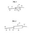
- FIG. 1is an isometric view of one embodiment of the present invention
- FIG. 2is an isometric view of the opposite side of the embodiment of FIG. 1 ;
- FIG. 3is a schematic view of a system of the present invention showing the embodiment of FIG. 1 attached to a bone;
- FIG. 4is an isometric view of a further embodiment of the present invention.
- FIG. 4 ais detailed view of the tip of the embodiment of FIG. 4 ;
- FIG. 4 bis a cross sectional view taken along the line 4 b - 4 b in FIG. 4 a;
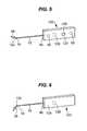
- FIG. 5is an isometric view of a still further embodiment of the present invention.
- FIG. 6is an isometric view of the opposite side of the embodiment of FIG. 5 ;
- FIG. 7is an isometric view of yet another embodiment of the present invention.
- FIG. 8is a schematic view showing the device of FIG. 5 attached to a bone and being rotated to determine the length of the section;
- FIG. 9is an block diagram of one embodiment of the method of the present invention.
- FIG. 10is a block diagram of a further embodiment of the method of the present invention.
- FIG. 11is an isometric view of yet another embodiment of the present invention.
- FIG. 12is a schematic view of the coupling of FIG. 4 showing the use of a position encoder
- FIG. 13is a detail view of an alternate tip of the embodiment of FIG. 1 ;
- FIG. 14is an isometric view of a still further embodiment of the present invention.
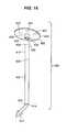
- FIG. 15is an isometric view of a yet additional embodiment of the present invention.
- FIG. 16is an exploded isometric view of another embodiment of the present invention.
- the present inventionis directed toward a small tracking device 50 that includes a section 52 having a distal end 54 and a proximal end 56 .
- a tip 58is located at the distal end 54 of the section 52 and a body 60 is located at the proximal end 56 of the section 52 .
- the section 52can be either rigid or flexible and can be made from any surgically acceptable material including surgical stainless steel, fiber optic glass fibers and the like.
- the proximal end 56 of the section 52is attached to the body 60 .
- Mounted on the body 60are two position-indicating devices 62 . Examples of suitable position-indicating devices 62 include light emitting diodes (LEDs), reflective surfaces, acoustic devices and the like.
- position-indicating devices 62are well known and will not be described further.
- a preferred position-indicating device 62is an LED that emits light in the infrared spectrum.
- the position-indicating devices 62will be in a fixed relationship to each other.
- the section 52is rigid and the distance from the tip 58 to the position-indicating devices 62 is known.
- the body 60has an electrical conductor 64 attached to the internal leads of the position-indicating devices 62 .
- the electrical conductor 64provides power to the position-indicating devices 62 and for active position-indicating devices such as LEDs also provides a signal when each position-indicating-device 62 is to illuminate.
- the body 60 and the position-indicating devices 62are constructed from materials that can be sterilized at least one time. If the tracking device 50 is to be reusable, then the materials chosen for the tracking device 50 must be capable of repeated sterilization. Alternatively, the tracking device 50 can be formed from a surgically acceptable plastic that can be prepackaged in a sterile state and is discarded after a single use.
- the body 60should be relatively small and lightweight.
- the body 60can be made from the same materials as the section 52 or from different surgically acceptable materials.
- the materials used for the body 60are lightweight so that the section 52 can be as thin as possible and if the section 52 is rigid, the weight of the body 60 will not cause the rigid section 52 to flex in use.
- the cross section of the section 52is small relative to the length of the section 52 .
- the length of the section 52need only be long enough so that the tip 58 can be attached to the bone or other anatomical structure and the body 60 is located outside the skin of the patient.
- the length of the section 52 from the tip 58 to the body 60can be from about 1.5 to about 3.5 cm.
- the small nature of the cross section of the section 52is very important so that the intrusion into the body of the patient is minimized.
- the section 52needs to be thick enough so that if the section 52 is rigid and does not include a joint as discussed below, there will be no relative movement between the tip 58 and the body 60 .
- the cross sectioncan be any shape, but typically will be circular and preferably have a dimension of between about 1.5 and about 3.5 mm.
- the most preferred dimension for the cross section of the section 52is between about 1.5 mm and about 2.5 mm.
- FIG. 1shows the tracking device 50 with two position-indicating devices 62 located collinear with the axis of the section 52 . It is possible, as will be discussed later, to include more than two position-indicating devices 62 on the tracking device 50 and these position-indicating devices 62 can be arranged in any suitable arrangement, including being arranged in locations not collinear with the axis of the section 52 , so long as the relationship among the position-indicating devices 62 is known. The distance between the position-indicating devices 62 on the body 60 need not be great. In fact, the position-indicating devices 62 can be located 2 mm from each other. The only requirement of the spacing of the position-indicating devices 62 is that the system can distinguish the emissions from each position-indicating device 62 from the next position indicating device 62 . It is also possible to use a single position-indicating device 62 so long as a sufficient number of tracking devices 50 are attached to the anatomical structure.
- FIG. 3shows the attachment of multiple tracking devices 50 to a bone 70 surrounded by tissue and skin 72 , represented by the three patches of skin 72 as shown in FIG. 3 .
- Each tracking device 50is anchored to the bone 70 .
- the minimum number of tracking devices 50 attached to the bone 70 to adequately track the location and orientation of the bone 70depends on the exact configuration of the tracking device 50 .
- each tracking devicecan have one, two, three, or more position indicating devices 62 . Further the number of tracking devices 50 necessary to adequately track the location and orientation of the bone 70 can also vary. Often more than the minimum number of tracking devices 50 will be used so that the system will constantly be able to see the minimum number of position-indicating devices 62 as the surgeon manipulates the anatomy or as the surgeon temporarily will block the field of view of the system.
- a communication device 74 having a body 76 and a series of quick connect connectors 78are attached to the electrical conductors 64 .
- the communications device 74has a transceiver 80 (represented by the transceiver window as shown) and a battery 82 .
- the communications device 74communicates in a wireless manner to a conventional surgical navigation system 84 that can track the position-indicating devices 62 .
- the surgical navigation systemis one well known in the art such as the system disclosed in U.S. Patent Publication No. 2001/034530, the disclosure of which is hereby incorporated by reference. It is also possible that the communication device 74 communicates with the surgical navigation system 84 using a hard-wired connection (not shown).
- the surgical navigation system 84includes a display device 86 , such as a computer monitor, to display the location of the various tracked devices 50 .
- a display device 86such as a computer monitor, to display the location of the various tracked devices 50 .
- the tracking devices 50move with the bone and the position and orientation of the bone 70 can be tracked by the surgical navigation system 84 and displayed on the display device 86 .
- FIG. 4shows an alternative embodiment of a tracking device 100 of the present invention.
- the tracking device 100has the body 60 , position-indicating devices 62 , and the section 52 , all similar to the device shown in FIG. 1 .
- the tip 58is attached to the distal end 54 of the section 52 by a coupling 102 .
- the details of the coupling 102are shown in FIGS. 4 a and 4 b .
- the coupling 102has a rotating joint 104 that includes an undercut 106 that allows the distal end 54 and the tip 58 to freely rotate relative to each other.
- the rotating joint 104is connected to a pivot joint 108 that includes a pivot pin 110 .
- the pivot joint 108allows the tip 58 to pivot relative to the section 52 of the device 100 .
- the device 100can rotate in three dimensions relative to the tip 58 . This is also referred to as having two degrees of freedom.
- the position-indicating devices 62are located collinearly with the axis of the section 52 . This enables the user to rotate the tracking device 100 so that the position-indicating devices 62 are always visible to the surgical navigation system 84 . Because the relation between the joint 56 and the position-indicating devices 62 is known as indicated by the distance D, the tracking device 100 can be rotated and need not be recalibrated before the tracking device 100 can be properly tracked by the surgical navigation system 84 . For the tracking device 100 , at least three tracking devices 100 are needed to fully track the underlying anatomy.
- FIGS. 5 and 6show a further embodiment of a tracking device 120 .
- the tracking device 120is similar to tracking device 50 .
- the tip 58is joined to the section 52 by a hinge joint 122 that is capable of hinging as shown.
- the hinge joint 122has a single degree of freedom. This enables the tracking device 120 to easily be positioned for maximum visibility and also enables the tracking device to be calibrated in position as will be discussed below.
- the tracking device 120has a body 124 that includes multiple position-indicating devices 62 .
- the body 124also includes a transceiver window 126 that covers a transceiver device capable of communication with a similar device in the surgical navigation system 84 in the same manner as the transceiver 80 as shown in FIG. 3 .
- the tracking device 120also includes its own self contained power supply 128 , located within the body 124 and therefore shown in phantom, to power the transceiver 126 and the position-indicating devices 62 .
- the tracking device 120a minimum of at least two tracking devices 120 are needed to properly track the underlying anatomical structure.
- FIG. 7shows a further embodiment of a tracking device 150 of the present invention.
- the tracking device 150includes a section 152 having a distal end 154 and a proximal end 156 .
- the proximal end 156is attached to a body 160 that is attached such that the body 160 is perpendicular to the axis of the section 152 .
- the body 152includes multiple position-indicating devices 162 , three such devices are shown, and a transceiver 164 .
- Internal to the body 160is a battery 166 , shown in phantom.
- the distal end 154has a tip 158 attached by a joint 168 .
- the joint 168can be either the joint as shown in FIG. 4 or the hinging joint as shown in FIG. 5 .
- the joint 168can be eliminated and the section 152 can be rigid from the proximal end 156 to the tip 158 .
- FIG. 8shows the tracking device 150 attached at a point 180 to a bone 182 .
- the tracking device 150can be rotated about the point 180 as indicated by the arrows 184 .
- Thisis a known method of calibrating a tracking device such as tracking device 150 in the field.
- the position-indicating devices 62travel in an arc that forms a cone.
- the surgical navigation system 84can track the position-indicating devices 62 and can then calculate the position 180 of attachment of the tracking device 150 to the bone 182 . Because of the sensitivity of the surgical navigation system 84 , only a small arc is needed to determine the length of the section 52 . Therefore, the joint 122 is preferably located just above the cortex of the bone 182 and also below the skin of the patient. There will be sufficient motion to enable the surgical navigation system to locate the position of the joint 122 relative to the position-indicating devices 62 .
- FIG. 9is a block diagram of the method steps of the present invention. At least two tracking devices such as the tracking device 50 are attached to a bone as indicated in the first step.
- the surgical navigation system 84determines the location of the tracking devices by locating the position-indicating devices 62 . From the location of the tracking devices, the surgical navigation system 84 can determine the position of the anatomical structure, usually a bone. Typically, the surgical navigation system will display the position of the structure on the display 86 .
- FIG. 10shows a further block diagram of an alternative method of the present invention.
- the position of a first tracking deviceis determined as has been described previously relative to the various tracking devices.
- the position of a second tracking deviceis also determined in a similar manner.
- the position of the tracking device relative to the point of attachment to the anatomical structureis determined. This position is determined either based on the relative location of the tip 58 and the position-indicating devices 62 for fixed or rigid systems or as described below for non-rigid systems.
- the position and orientation of the anatomical structureis determined. The determination is done using methods well known to those of skill in the art of computer assisted surgical navigation systems.
- FIG. 11shows a still added embodiment of a tracking device 200 .
- the tracking device 200has a flexible section 202 having a distal end 204 and a proximal end 206 .
- the flexible section 202can be a pair of fiber optic filaments 202 a .
- the body 60is attached to the proximal end 206 and includes position-indicating devices 62 , the battery 128 , the transceiver 126 and a fiber optic decoding device 208 .
- the fiber optic deciding device 208can determined the relative location of the tip 58 relative to the body 60 based on the amount of light that is returned by the return fiber optic element of the fiber optic pair 202 a .
- This relative position of the tip 58 to the body 60can be transmitted to the surgical navigation system 84 by the transceiver 126 .
- Co-pending application Ser. No. 10/798,614, filed Mar. 11, 2004,has more detail on the functioning of the fiber optic pair to determine relative location and the disclosure of this application is hereby incorporated by reference.
- Other similar devicescan be used such as strain gauges and the like.
- sensors built into the joint itselfcan determine the relative position. In this case, the relative position of the joint can be determined by electrical resistance changes, capacitance changes, magnetic sensors, and the like.
- the tracking device 200can properly define the location of the underlying anatomy with a single tracking device 200 .
- FIG. 12shows an electric resistance encoder arrangement in a joint 300 .
- a ball 302contacts a resistive surface 304 that is electrically connected at ends 306 and 308 to an encoder device 310 .
- the ball 302is spring loaded to assure contact with the resistive surface 304 and the ball is also electrically connected to the encoder 310 .
- the encoder 310Based on the relative resistance between the ends 306 and 308 of the resistive surface 304 and the ball 302 , the encoder 310 can determine the relative position of the joint 300 .
- FIG. 13shows an alternative embodiment of the tip 58 .
- the tip 58can either be a barb as shown in the prior figures or can be a screw device 220 as shown.
- other methods of affixing the section 52 to the bonecan also be used, such as surgical nails, adhesives and the like.
- FIG. 14depicts a tracking device 350 that has a section 352 , a distal end 354 of the section 352 and a proximal end 356 of the section 352 .
- the distal end 354includes an integrally formed tip 358 and the proximal end 356 includes an integrally formed body area 360 .
- the body area 360includes a single position indicating device 362 , a battery 364 (shown in phantom) contained within the body area 360 and a transceiver 366 to communicate with the surgical navigation system 84 .
- the tip 358 , the section 352 and the body area 360are all formed from the same material.
- the tracking device 350can be formed from materials that can be pre-sterilized for single use. A minimum of three of the tracking devices 350 are needed to define a location of the underlying anatomy for the surgical navigation system 84 .
- FIG. 15shows a tracking device 380 that is similar to the device 350 shown in FIG. 14 .
- the tracking device 380has a body area 382 that is integral with the section 352 and the body area 382 includes two position-indicating devices 384 .
- a tracking device 400has a separate section 402 .
- the section 402has a distal end 404 and a proximal end 406 . In use, the section 402 is cut at a point 408 to remove a portion 410 of the section 402 .
- the section 402is shortened to a length just above the skin of the patient to minimize interference with the surgical site and to maximize ergonomics.
- the distal end 404is connected to a tip 412 by a joint 414 similar to those discussed previously.
- the tracking device 400also has a separate body 420 that includes on its top surface a series of tracking sensors 422 and a transceiver window 424 (both shown in phantom).
- the body 420also has a coupling 426 that has an opening 428 .
- the inside wall of the coupling 426also has a series of flexible bayonet structures 430 spaced around the interior of the coupling 426 .
- bayonet structures 430will engage the section 402 as it is inserted into the coupling 426 and hold the section 402 firmly in place.
- the cross section of the section 402 and the opening 428should match and they may be a shape other than circular to minimize relative movement of the body 420 and the section 402 .
Landscapes
- Health & Medical Sciences (AREA)
- Surgery (AREA)
- Life Sciences & Earth Sciences (AREA)
- Engineering & Computer Science (AREA)
- Heart & Thoracic Surgery (AREA)
- Animal Behavior & Ethology (AREA)
- Veterinary Medicine (AREA)
- Biomedical Technology (AREA)
- Nuclear Medicine, Radiotherapy & Molecular Imaging (AREA)
- Medical Informatics (AREA)
- Molecular Biology (AREA)
- Public Health (AREA)
- General Health & Medical Sciences (AREA)
- Pathology (AREA)
- Oral & Maxillofacial Surgery (AREA)
- Robotics (AREA)
- Surgical Instruments (AREA)
- Manipulator (AREA)
Abstract
Description
Claims (59)
Priority Applications (2)
| Application Number | Priority Date | Filing Date | Title |
|---|---|---|---|
| US10/939,225US8290570B2 (en) | 2004-09-10 | 2004-09-10 | System for ad hoc tracking of an object |
| DE102005042751.0ADE102005042751B4 (en) | 2004-09-10 | 2005-09-08 | System, device and method for ad hoc tracking of an object |
Applications Claiming Priority (1)
| Application Number | Priority Date | Filing Date | Title |
|---|---|---|---|
| US10/939,225US8290570B2 (en) | 2004-09-10 | 2004-09-10 | System for ad hoc tracking of an object |
Publications (2)
| Publication Number | Publication Date |
|---|---|
| US20060058644A1 US20060058644A1 (en) | 2006-03-16 |
| US8290570B2true US8290570B2 (en) | 2012-10-16 |
Family
ID=36035033
Family Applications (1)
| Application Number | Title | Priority Date | Filing Date |
|---|---|---|---|
| US10/939,225Active2029-11-23US8290570B2 (en) | 2004-09-10 | 2004-09-10 | System for ad hoc tracking of an object |
Country Status (2)
| Country | Link |
|---|---|
| US (1) | US8290570B2 (en) |
| DE (1) | DE102005042751B4 (en) |
Cited By (10)
| Publication number | Priority date | Publication date | Assignee | Title |
|---|---|---|---|---|
| US9387008B2 (en) | 2011-09-08 | 2016-07-12 | Stryker European Holdings I, Llc | Axial surgical trajectory guide, and method of guiding a medical device |
| US9498231B2 (en) | 2011-06-27 | 2016-11-22 | Board Of Regents Of The University Of Nebraska | On-board tool tracking system and methods of computer assisted surgery |
| US10105149B2 (en) | 2013-03-15 | 2018-10-23 | Board Of Regents Of The University Of Nebraska | On-board tool tracking system and methods of computer assisted surgery |
| US10219811B2 (en) | 2011-06-27 | 2019-03-05 | Board Of Regents Of The University Of Nebraska | On-board tool tracking system and methods of computer assisted surgery |
| FR3080017A1 (en)* | 2018-04-16 | 2019-10-18 | Pytheas Navigation | QUICK CALIBRATION SYSTEM FOR SURGICAL NAVIGATION |
| US11116574B2 (en) | 2006-06-16 | 2021-09-14 | Board Of Regents Of The University Of Nebraska | Method and apparatus for computer aided surgery |
| US20230248446A1 (en)* | 2019-09-05 | 2023-08-10 | Nuvasive, Inc. | Surgical instrument tracking devices and related methods |
| US11911117B2 (en) | 2011-06-27 | 2024-02-27 | Board Of Regents Of The University Of Nebraska | On-board tool tracking system and methods of computer assisted surgery |
| US12178522B2 (en) | 2018-05-25 | 2024-12-31 | Mako Surgical Corp. | Versatile tracking arrays for a navigation system and methods of recovering registration using the same |
| US12369988B2 (en) | 2021-01-06 | 2025-07-29 | Mako Surgical Corp. | Tracker for a navigation system |
Families Citing this family (24)
| Publication number | Priority date | Publication date | Assignee | Title |
|---|---|---|---|---|
| EP1605810A2 (en)* | 2003-02-04 | 2005-12-21 | Z-Kat, Inc. | Computer-assisted knee replacement apparatus and method |
| WO2004069040A2 (en)* | 2003-02-04 | 2004-08-19 | Z-Kat, Inc. | Method and apparatus for computer assistance with intramedullary nail procedure |
| US7771436B2 (en)* | 2003-12-10 | 2010-08-10 | Stryker Leibinger Gmbh & Co. Kg. | Surgical navigation tracker, system and method |
| US20050267353A1 (en)* | 2004-02-04 | 2005-12-01 | Joel Marquart | Computer-assisted knee replacement apparatus and method |
| US20070016008A1 (en)* | 2005-06-23 | 2007-01-18 | Ryan Schoenefeld | Selective gesturing input to a surgical navigation system |
| US7840256B2 (en) | 2005-06-27 | 2010-11-23 | Biomet Manufacturing Corporation | Image guided tracking array and method |
| US20070073133A1 (en)* | 2005-09-15 | 2007-03-29 | Schoenefeld Ryan J | Virtual mouse for use in surgical navigation |
| US7643862B2 (en)* | 2005-09-15 | 2010-01-05 | Biomet Manufacturing Corporation | Virtual mouse for use in surgical navigation |
| US8165659B2 (en) | 2006-03-22 | 2012-04-24 | Garrett Sheffer | Modeling method and apparatus for use in surgical navigation |
| US20080071195A1 (en)* | 2006-09-18 | 2008-03-20 | Cuellar Alberto D | Non-invasive tracking device and method |
| US20080086051A1 (en)* | 2006-09-20 | 2008-04-10 | Ethicon Endo-Surgery, Inc. | System, storage medium for a computer program, and method for displaying medical images |
| US20080319307A1 (en)* | 2007-06-19 | 2008-12-25 | Ethicon Endo-Surgery, Inc. | Method for medical imaging using fluorescent nanoparticles |
| US8457718B2 (en)* | 2007-03-21 | 2013-06-04 | Ethicon Endo-Surgery, Inc. | Recognizing a real world fiducial in a patient image data |
| US8155728B2 (en)* | 2007-08-22 | 2012-04-10 | Ethicon Endo-Surgery, Inc. | Medical system, method, and storage medium concerning a natural orifice transluminal medical procedure |
| US20080221434A1 (en)* | 2007-03-09 | 2008-09-11 | Voegele James W | Displaying an internal image of a body lumen of a patient |
| EP2120839A2 (en)* | 2007-03-14 | 2009-11-25 | Kathryn A. Mckenzie Waitzman | Methods and systems for locating a feeding tube inside of a patient |
| US20080234544A1 (en)* | 2007-03-20 | 2008-09-25 | Ethicon Endo-Sugery, Inc. | Displaying images interior and exterior to a body lumen of a patient |
| US8081810B2 (en)* | 2007-03-22 | 2011-12-20 | Ethicon Endo-Surgery, Inc. | Recognizing a real world fiducial in image data of a patient |
| US8934961B2 (en) | 2007-05-18 | 2015-01-13 | Biomet Manufacturing, Llc | Trackable diagnostic scope apparatus and methods of use |
| US20080319491A1 (en) | 2007-06-19 | 2008-12-25 | Ryan Schoenefeld | Patient-matched surgical component and methods of use |
| US8571637B2 (en)* | 2008-01-21 | 2013-10-29 | Biomet Manufacturing, Llc | Patella tracking method and apparatus for use in surgical navigation |
| EP2179703B1 (en)* | 2008-10-21 | 2012-03-28 | BrainLAB AG | Integration of surgical instrument and display device for supporting image-based surgery |
| US9192445B2 (en) | 2012-12-13 | 2015-11-24 | Mako Surgical Corp. | Registration and navigation using a three-dimensional tracking sensor |
| WO2015144246A1 (en)* | 2014-03-28 | 2015-10-01 | Brainlab Ag | Instrument for creating an artificial landmark on a surface of a bone and medical navigation system |
Citations (65)
| Publication number | Priority date | Publication date | Assignee | Title |
|---|---|---|---|---|
| US4323459A (en) | 1978-08-09 | 1982-04-06 | Petrolite Corporation | Process of inhibiting scale formation in aqueous systems using quaternary ammonium salts of α-1,4-thiazine alkanephosphonic acids |
| US4396945A (en) | 1981-08-19 | 1983-08-02 | Solid Photography Inc. | Method of sensing the position and orientation of elements in space |
| US4722056A (en) | 1986-02-18 | 1988-01-26 | Trustees Of Dartmouth College | Reference display systems for superimposing a tomagraphic image onto the focal plane of an operating microscope |
| EP0326768A2 (en) | 1988-02-01 | 1989-08-09 | Faro Medical Technologies Inc. | Computer-aided surgery apparatus |
| US4869247A (en) | 1988-03-11 | 1989-09-26 | The University Of Virginia Alumni Patents Foundation | Video tumor fighting system |
| DE3904595C1 (en) | 1989-02-16 | 1990-04-19 | Deutsches Krebsforschungszentrum Stiftung Des Oeffentlichen Rechts, 6900 Heidelberg, De | Device for determining the spatial coordinates of stereotactic target points by means of X-ray pictures |
| US4923459A (en) | 1987-09-14 | 1990-05-08 | Kabushiki Kaisha Toshiba | Stereotactics apparatus |
| WO1990005494A1 (en) | 1988-11-18 | 1990-05-31 | Istituto Neurologico 'carlo Besta' | Process and apparatus particularly for guiding neurosurgical operations |
| US4945914A (en) | 1987-11-10 | 1990-08-07 | Allen George S | Method and apparatus for providing related images over time of a portion of the anatomy using at least four fiducial implants |
| US4951653A (en) | 1988-03-02 | 1990-08-28 | Laboratory Equipment, Corp. | Ultrasound brain lesioning system |
| JPH03267054A (en) | 1990-03-16 | 1991-11-27 | Amayoshi Katou | Stationary lobotomy aid |
| US5142930A (en) | 1987-11-10 | 1992-09-01 | Allen George S | Interactive image-guided surgical system |
| US5186174A (en) | 1987-05-21 | 1993-02-16 | G. M. Piaff | Process and device for the reproducible optical representation of a surgical operation |
| US5198877A (en) | 1990-10-15 | 1993-03-30 | Pixsys, Inc. | Method and apparatus for three-dimensional non-contact shape sensing |
| US5222499A (en) | 1989-11-15 | 1993-06-29 | Allen George S | Method and apparatus for imaging the anatomy |
| US5309101A (en) | 1993-01-08 | 1994-05-03 | General Electric Company | Magnetic resonance imaging in an inhomogeneous magnetic field |
| JPH06282890A (en) | 1994-01-31 | 1994-10-07 | Sharp Corp | Magneto-optical memory device |
| JPH06282889A (en) | 1994-01-31 | 1994-10-07 | Sharp Corp | Magneto-optical memory cell |
| US5383454A (en) | 1990-10-19 | 1995-01-24 | St. Louis University | System for indicating the position of a surgical probe within a head on an image of the head |
| US5394875A (en) | 1993-10-21 | 1995-03-07 | Lewis; Judith T. | Automatic ultrasonic localization of targets implanted in a portion of the anatomy |
| US5494034A (en) | 1987-05-27 | 1996-02-27 | Georg Schlondorff | Process and device for the reproducible optical representation of a surgical operation |
| US5515160A (en) | 1992-03-12 | 1996-05-07 | Aesculap Ag | Method and apparatus for representing a work area in a three-dimensional structure |
| US5551429A (en) | 1993-02-12 | 1996-09-03 | Fitzpatrick; J. Michael | Method for relating the data of an image space to physical space |
| US5575794A (en) | 1993-02-12 | 1996-11-19 | Walus; Richard L. | Tool for implanting a fiducial marker |
| US5590215A (en) | 1993-10-15 | 1996-12-31 | Allen; George S. | Method for providing medical images |
| US5617857A (en) | 1995-06-06 | 1997-04-08 | Image Guided Technologies, Inc. | Imaging system having interactive medical instruments and methods |
| US5622170A (en) | 1990-10-19 | 1997-04-22 | Image Guided Technologies, Inc. | Apparatus for determining the position and orientation of an invasive portion of a probe inside a three-dimensional body |
| US5638819A (en) | 1995-08-29 | 1997-06-17 | Manwaring; Kim H. | Method and apparatus for guiding an instrument to a target |
| US5665090A (en) | 1992-09-09 | 1997-09-09 | Dupuy Inc. | Bone cutting apparatus and method |
| US5695501A (en) | 1994-09-30 | 1997-12-09 | Ohio Medical Instrument Company, Inc. | Apparatus for neurosurgical stereotactic procedures |
| US5704897A (en) | 1992-07-31 | 1998-01-06 | Truppe; Michael J. | Apparatus and method for registration of points of a data field with respective points of an optical image |
| US5711299A (en) | 1996-01-26 | 1998-01-27 | Manwaring; Kim H. | Surgical guidance method and system for approaching a target within a body |
| US5752513A (en) | 1995-06-07 | 1998-05-19 | Biosense, Inc. | Method and apparatus for determining position of object |
| US5769789A (en) | 1993-02-12 | 1998-06-23 | George S. Allen | Automatic technique for localizing externally attached fiducial markers in volume images of the head |
| US5797924A (en) | 1993-11-02 | 1998-08-25 | Loma Linda University Medical Center | Stereotactic fixation system and calibration phantom |
| US5871445A (en) | 1993-04-26 | 1999-02-16 | St. Louis University | System for indicating the position of a surgical probe within a head on an image of the head |
| US5880976A (en) | 1997-02-21 | 1999-03-09 | Carnegie Mellon University | Apparatus and method for facilitating the implantation of artificial components in joints |
| US5891157A (en) | 1994-09-30 | 1999-04-06 | Ohio Medical Instrument Company, Inc. | Apparatus for surgical stereotactic procedures |
| US5907395A (en) | 1997-06-06 | 1999-05-25 | Image Guided Technologies, Inc. | Optical fiber probe for position measurement |
| US5921992A (en) | 1997-04-11 | 1999-07-13 | Radionics, Inc. | Method and system for frameless tool calibration |
| US5954648A (en) | 1996-04-29 | 1999-09-21 | U.S. Philips Corporation | Image guided surgery system |
| US5970499A (en) | 1997-04-11 | 1999-10-19 | Smith; Kurt R. | Method and apparatus for producing and accessing composite data |
| US6081336A (en) | 1997-09-26 | 2000-06-27 | Picker International, Inc. | Microscope calibrator |
| WO2000039576A1 (en) | 1998-12-23 | 2000-07-06 | Image Guided Technologies, Inc. | A hybrid 3-d probe tracked by multiple sensors |
| US6112113A (en) | 1997-07-03 | 2000-08-29 | U.S. Philips Corporation | Image-guided surgery system |
| US6205411B1 (en) | 1997-02-21 | 2001-03-20 | Carnegie Mellon University | Computer-assisted surgery planner and intra-operative guidance system |
| US20010034530A1 (en) | 2000-01-27 | 2001-10-25 | Malackowski Donald W. | Surgery system |
| US6409686B1 (en)* | 1994-01-24 | 2002-06-25 | Sherwood Services Ag | Virtual probe for a stereotactic digitizer for use in surgery |
| US6430434B1 (en) | 1998-12-14 | 2002-08-06 | Integrated Surgical Systems, Inc. | Method for determining the location and orientation of a bone for computer-assisted orthopedic procedures using intraoperatively attached markers |
| WO2002063236A2 (en) | 2001-02-07 | 2002-08-15 | Aesculap Ag & Co. Kg | Method and device for determining the contour of a recess in a piece of material |
| US6453190B1 (en) | 1996-02-15 | 2002-09-17 | Biosense, Inc. | Medical probes with field transducers |
| US20030153829A1 (en) | 2002-02-13 | 2003-08-14 | Kinamed, Inc. | Non-imaging, computer assisted navigation system for hip replacement surgery |
| US20030187351A1 (en)* | 1998-04-21 | 2003-10-02 | Neutar L.L.C., A Maine Corporation | Instrument guidance system for spinal and other surgery |
| US6676706B1 (en) | 2000-04-26 | 2004-01-13 | Zimmer Technology, Inc. | Method and apparatus for performing a minimally invasive total hip arthroplasty |
| WO2004014219A2 (en) | 2002-08-09 | 2004-02-19 | Kinamed, Inc. | Non-imaging tracking tools and method for hip replacement surgery |
| US20040034313A1 (en) | 2000-12-15 | 2004-02-19 | Aesculap Ag & Co. Kg | Method and device for determining the mechanical axis of a femur |
| US6695850B2 (en) | 2002-02-20 | 2004-02-24 | Robert L. Diaz | Minimally invasive total hip replacement |
| WO2004030559A1 (en) | 2002-10-04 | 2004-04-15 | Orthosoft Inc. | A method for providing pelvic orientation information in computer-assisted surgery |
| EP1417941A1 (en) | 2002-11-05 | 2004-05-12 | BrainLAB AG | Method and device for registering a femoral implant |
| US20040097952A1 (en)* | 2002-02-13 | 2004-05-20 | Sarin Vineet Kumar | Non-image, computer assisted navigation system for joint replacement surgery with modular implant system |
| US20050085715A1 (en)* | 2003-10-17 | 2005-04-21 | Dukesherer John H. | Method and apparatus for surgical navigation |
| US20070016009A1 (en)* | 2005-06-27 | 2007-01-18 | Lakin Ryan C | Image guided tracking array and method |
| US20100160771A1 (en)* | 2007-04-24 | 2010-06-24 | Medtronic, Inc. | Method and Apparatus for Performing a Navigated Procedure |
| US8012107B2 (en)* | 2004-02-05 | 2011-09-06 | Motorika Limited | Methods and apparatus for rehabilitation and training |
| US20120004668A1 (en)* | 2004-03-05 | 2012-01-05 | Hansen Medical, Inc. | Robotic catheter system |
Family Cites Families (2)
| Publication number | Priority date | Publication date | Assignee | Title |
|---|---|---|---|---|
| JP2005516724A (en)* | 2002-02-11 | 2005-06-09 | スミス アンド ネフュー インコーポレーテッド | Image guided fracture reduction |
| US20040030237A1 (en)* | 2002-07-29 | 2004-02-12 | Lee David M. | Fiducial marker devices and methods |
- 2004
- 2004-09-10USUS10/939,225patent/US8290570B2/enactiveActive
- 2005
- 2005-09-08DEDE102005042751.0Apatent/DE102005042751B4/ennot_activeExpired - Fee Related
Patent Citations (88)
| Publication number | Priority date | Publication date | Assignee | Title |
|---|---|---|---|---|
| US4323459A (en) | 1978-08-09 | 1982-04-06 | Petrolite Corporation | Process of inhibiting scale formation in aqueous systems using quaternary ammonium salts of α-1,4-thiazine alkanephosphonic acids |
| US4396945A (en) | 1981-08-19 | 1983-08-02 | Solid Photography Inc. | Method of sensing the position and orientation of elements in space |
| US4722056A (en) | 1986-02-18 | 1988-01-26 | Trustees Of Dartmouth College | Reference display systems for superimposing a tomagraphic image onto the focal plane of an operating microscope |
| US5186174A (en) | 1987-05-21 | 1993-02-16 | G. M. Piaff | Process and device for the reproducible optical representation of a surgical operation |
| US5494034A (en) | 1987-05-27 | 1996-02-27 | Georg Schlondorff | Process and device for the reproducible optical representation of a surgical operation |
| US4923459A (en) | 1987-09-14 | 1990-05-08 | Kabushiki Kaisha Toshiba | Stereotactics apparatus |
| US4945914A (en) | 1987-11-10 | 1990-08-07 | Allen George S | Method and apparatus for providing related images over time of a portion of the anatomy using at least four fiducial implants |
| US5397329A (en) | 1987-11-10 | 1995-03-14 | Allen; George S. | Fiducial implant and system of such implants |
| US5230338A (en) | 1987-11-10 | 1993-07-27 | Allen George S | Interactive image-guided surgical system for displaying images corresponding to the placement of a surgical tool or the like |
| US4991579A (en) | 1987-11-10 | 1991-02-12 | Allen George S | Method and apparatus for providing related images over time of a portion of the anatomy using fiducial implants |
| US5016639A (en) | 1987-11-10 | 1991-05-21 | Allen George S | Method and apparatus for imaging the anatomy |
| US5211164A (en) | 1987-11-10 | 1993-05-18 | Allen George S | Method of locating a target on a portion of anatomy |
| US5094241A (en) | 1987-11-10 | 1992-03-10 | Allen George S | Apparatus for imaging the anatomy |
| US5097839A (en) | 1987-11-10 | 1992-03-24 | Allen George S | Apparatus for imaging the anatomy |
| US5119817A (en) | 1987-11-10 | 1992-06-09 | Allen George S | Apparatus for imaging the anatomy |
| US5142930A (en) | 1987-11-10 | 1992-09-01 | Allen George S | Interactive image-guided surgical system |
| US5178164A (en) | 1987-11-10 | 1993-01-12 | Allen George S | Method for implanting a fiducial implant into a patient |
| EP0326768A2 (en) | 1988-02-01 | 1989-08-09 | Faro Medical Technologies Inc. | Computer-aided surgery apparatus |
| US4951653A (en) | 1988-03-02 | 1990-08-28 | Laboratory Equipment, Corp. | Ultrasound brain lesioning system |
| US4869247A (en) | 1988-03-11 | 1989-09-26 | The University Of Virginia Alumni Patents Foundation | Video tumor fighting system |
| WO1990005494A1 (en) | 1988-11-18 | 1990-05-31 | Istituto Neurologico 'carlo Besta' | Process and apparatus particularly for guiding neurosurgical operations |
| DE3904595C1 (en) | 1989-02-16 | 1990-04-19 | Deutsches Krebsforschungszentrum Stiftung Des Oeffentlichen Rechts, 6900 Heidelberg, De | Device for determining the spatial coordinates of stereotactic target points by means of X-ray pictures |
| US5222499A (en) | 1989-11-15 | 1993-06-29 | Allen George S | Method and apparatus for imaging the anatomy |
| JPH03267054A (en) | 1990-03-16 | 1991-11-27 | Amayoshi Katou | Stationary lobotomy aid |
| US5198877A (en) | 1990-10-15 | 1993-03-30 | Pixsys, Inc. | Method and apparatus for three-dimensional non-contact shape sensing |
| USRE35816E (en) | 1990-10-15 | 1998-06-02 | Image Guided Technologies Inc. | Method and apparatus for three-dimensional non-contact shape sensing |
| US5851183A (en) | 1990-10-19 | 1998-12-22 | St. Louis University | System for indicating the position of a surgical probe within a head on an image of the head |
| US5383454A (en) | 1990-10-19 | 1995-01-24 | St. Louis University | System for indicating the position of a surgical probe within a head on an image of the head |
| US5891034A (en) | 1990-10-19 | 1999-04-06 | St. Louis University | System for indicating the position of a surgical probe within a head on an image of the head |
| US5987349A (en) | 1990-10-19 | 1999-11-16 | Image Guided Technologies, Inc. | Method for determining the position and orientation of two moveable objects in three-dimensional space |
| US5622170A (en) | 1990-10-19 | 1997-04-22 | Image Guided Technologies, Inc. | Apparatus for determining the position and orientation of an invasive portion of a probe inside a three-dimensional body |
| US5383454B1 (en) | 1990-10-19 | 1996-12-31 | Univ St Louis | System for indicating the position of a surgical probe within a head on an image of the head |
| US5515160A (en) | 1992-03-12 | 1996-05-07 | Aesculap Ag | Method and apparatus for representing a work area in a three-dimensional structure |
| US5704897A (en) | 1992-07-31 | 1998-01-06 | Truppe; Michael J. | Apparatus and method for registration of points of a data field with respective points of an optical image |
| US5665090A (en) | 1992-09-09 | 1997-09-09 | Dupuy Inc. | Bone cutting apparatus and method |
| US5309101A (en) | 1993-01-08 | 1994-05-03 | General Electric Company | Magnetic resonance imaging in an inhomogeneous magnetic field |
| US5730130A (en) | 1993-02-12 | 1998-03-24 | Johnson & Johnson Professional, Inc. | Localization cap for fiducial markers |
| US5575794A (en) | 1993-02-12 | 1996-11-19 | Walus; Richard L. | Tool for implanting a fiducial marker |
| US6073044A (en) | 1993-02-12 | 2000-06-06 | Fitzpatrick; J. Michael | Method for determining the location in physical space of a point of fiducial marker that is selectively detachable to a base |
| US5595193A (en) | 1993-02-12 | 1997-01-21 | Walus; Richard L. | Tool for implanting a fiducial marker |
| US5916164A (en) | 1993-02-12 | 1999-06-29 | George S. Allen | Localization cap for fiducial markers |
| US5799099A (en) | 1993-02-12 | 1998-08-25 | George S. Allen | Automatic technique for localizing externally attached fiducial markers in volume images of the head |
| US5769789A (en) | 1993-02-12 | 1998-06-23 | George S. Allen | Automatic technique for localizing externally attached fiducial markers in volume images of the head |
| US5551429A (en) | 1993-02-12 | 1996-09-03 | Fitzpatrick; J. Michael | Method for relating the data of an image space to physical space |
| US5871445A (en) | 1993-04-26 | 1999-02-16 | St. Louis University | System for indicating the position of a surgical probe within a head on an image of the head |
| US5590215A (en) | 1993-10-15 | 1996-12-31 | Allen; George S. | Method for providing medical images |
| US5394875A (en) | 1993-10-21 | 1995-03-07 | Lewis; Judith T. | Automatic ultrasonic localization of targets implanted in a portion of the anatomy |
| US5797924A (en) | 1993-11-02 | 1998-08-25 | Loma Linda University Medical Center | Stereotactic fixation system and calibration phantom |
| US6409686B1 (en)* | 1994-01-24 | 2002-06-25 | Sherwood Services Ag | Virtual probe for a stereotactic digitizer for use in surgery |
| JPH06282890A (en) | 1994-01-31 | 1994-10-07 | Sharp Corp | Magneto-optical memory device |
| JPH06282889A (en) | 1994-01-31 | 1994-10-07 | Sharp Corp | Magneto-optical memory cell |
| US5891157A (en) | 1994-09-30 | 1999-04-06 | Ohio Medical Instrument Company, Inc. | Apparatus for surgical stereotactic procedures |
| US5695501A (en) | 1994-09-30 | 1997-12-09 | Ohio Medical Instrument Company, Inc. | Apparatus for neurosurgical stereotactic procedures |
| US5617857A (en) | 1995-06-06 | 1997-04-08 | Image Guided Technologies, Inc. | Imaging system having interactive medical instruments and methods |
| US5752513A (en) | 1995-06-07 | 1998-05-19 | Biosense, Inc. | Method and apparatus for determining position of object |
| US5638819A (en) | 1995-08-29 | 1997-06-17 | Manwaring; Kim H. | Method and apparatus for guiding an instrument to a target |
| US5711299A (en) | 1996-01-26 | 1998-01-27 | Manwaring; Kim H. | Surgical guidance method and system for approaching a target within a body |
| US6453190B1 (en) | 1996-02-15 | 2002-09-17 | Biosense, Inc. | Medical probes with field transducers |
| US5954648A (en) | 1996-04-29 | 1999-09-21 | U.S. Philips Corporation | Image guided surgery system |
| US5880976A (en) | 1997-02-21 | 1999-03-09 | Carnegie Mellon University | Apparatus and method for facilitating the implantation of artificial components in joints |
| US6205411B1 (en) | 1997-02-21 | 2001-03-20 | Carnegie Mellon University | Computer-assisted surgery planner and intra-operative guidance system |
| US5970499A (en) | 1997-04-11 | 1999-10-19 | Smith; Kurt R. | Method and apparatus for producing and accessing composite data |
| US5921992A (en) | 1997-04-11 | 1999-07-13 | Radionics, Inc. | Method and system for frameless tool calibration |
| US5907395A (en) | 1997-06-06 | 1999-05-25 | Image Guided Technologies, Inc. | Optical fiber probe for position measurement |
| US6112113A (en) | 1997-07-03 | 2000-08-29 | U.S. Philips Corporation | Image-guided surgery system |
| US6081336A (en) | 1997-09-26 | 2000-06-27 | Picker International, Inc. | Microscope calibrator |
| US20030187351A1 (en)* | 1998-04-21 | 2003-10-02 | Neutar L.L.C., A Maine Corporation | Instrument guidance system for spinal and other surgery |
| US6430434B1 (en) | 1998-12-14 | 2002-08-06 | Integrated Surgical Systems, Inc. | Method for determining the location and orientation of a bone for computer-assisted orthopedic procedures using intraoperatively attached markers |
| WO2000039576A1 (en) | 1998-12-23 | 2000-07-06 | Image Guided Technologies, Inc. | A hybrid 3-d probe tracked by multiple sensors |
| US20010034530A1 (en) | 2000-01-27 | 2001-10-25 | Malackowski Donald W. | Surgery system |
| US6676706B1 (en) | 2000-04-26 | 2004-01-13 | Zimmer Technology, Inc. | Method and apparatus for performing a minimally invasive total hip arthroplasty |
| US20040034313A1 (en) | 2000-12-15 | 2004-02-19 | Aesculap Ag & Co. Kg | Method and device for determining the mechanical axis of a femur |
| EP1399707A2 (en) | 2001-02-07 | 2004-03-24 | Aesculap AG & Co. KG | Method and device for determining the contour of a recess in a piece of material |
| WO2002063236A2 (en) | 2001-02-07 | 2002-08-15 | Aesculap Ag & Co. Kg | Method and device for determining the contour of a recess in a piece of material |
| US20030153829A1 (en) | 2002-02-13 | 2003-08-14 | Kinamed, Inc. | Non-imaging, computer assisted navigation system for hip replacement surgery |
| WO2003073951A1 (en) | 2002-02-13 | 2003-09-12 | Kinamed, Inc. | Non-imaging, computer assisted navigation system for hip replacement surgery |
| US20040097952A1 (en)* | 2002-02-13 | 2004-05-20 | Sarin Vineet Kumar | Non-image, computer assisted navigation system for joint replacement surgery with modular implant system |
| US6711431B2 (en) | 2002-02-13 | 2004-03-23 | Kinamed, Inc. | Non-imaging, computer assisted navigation system for hip replacement surgery |
| US6695850B2 (en) | 2002-02-20 | 2004-02-24 | Robert L. Diaz | Minimally invasive total hip replacement |
| WO2004014219A2 (en) | 2002-08-09 | 2004-02-19 | Kinamed, Inc. | Non-imaging tracking tools and method for hip replacement surgery |
| WO2004030559A1 (en) | 2002-10-04 | 2004-04-15 | Orthosoft Inc. | A method for providing pelvic orientation information in computer-assisted surgery |
| WO2004030556A2 (en) | 2002-10-04 | 2004-04-15 | Orthosoft Inc. | Computer-assisted hip replacement surgery |
| EP1417941A1 (en) | 2002-11-05 | 2004-05-12 | BrainLAB AG | Method and device for registering a femoral implant |
| US20050085715A1 (en)* | 2003-10-17 | 2005-04-21 | Dukesherer John H. | Method and apparatus for surgical navigation |
| US8012107B2 (en)* | 2004-02-05 | 2011-09-06 | Motorika Limited | Methods and apparatus for rehabilitation and training |
| US20120004668A1 (en)* | 2004-03-05 | 2012-01-05 | Hansen Medical, Inc. | Robotic catheter system |
| US20070016009A1 (en)* | 2005-06-27 | 2007-01-18 | Lakin Ryan C | Image guided tracking array and method |
| US20100160771A1 (en)* | 2007-04-24 | 2010-06-24 | Medtronic, Inc. | Method and Apparatus for Performing a Navigated Procedure |
Non-Patent Citations (48)
| Title |
|---|
| "Hip Joint Anatomy," http://vv.totaljoints.info/HIPJOINT-anatomydetails.htm Oct. 7, 2003 (3 pages). |
| "Hip Joint Anatomy," http://vv.totaljoints.info/HIPJOINT—anatomydetails.htm Oct. 7, 2003 (3 pages). |
| "Hip: Functional Method," http://kwon3d.com/manuals/kwon3d30/modeling/hip-func.html Oct. 16, 2003 (4 pages). |
| "Hip: Functional Method," http://kwon3d.com/manuals/kwon3d30/modeling/hip—func.html Oct. 16, 2003 (4 pages). |
| "Inclination," http://www.gentili.net/thr/inclinat.htm Oct. 16, 2003 (1 page). |
| "Kinematik Approach to Hip Navigation," José Moctezuma Jul. 24, 2002 (4 pages). |
| "Radiographic and Non-Invasive Determination of the Hip Joint Center Location: Effect on Hip Joint Angles," R.N. Kirkwood et al. Oct. 16, 2003 (3 pages). |
| "Rx90® Total Hip System Acetabular Series," Biomet Orthopedics, Inc. 2001 (11 pages). |
| "Software Requirements Specification (SRS) Image Enhanced Knee Navigation, #1728," Richard Aschenbrenner Jun. 23, 2003 (46 pages). |
| "Surgical Steps for Computer Assisted Total Hip Arthroplasty," HipTrac V1.0 José Luis Moctezuma de la Barrera Jun. 4, 2000 (6 pages). |
| "Virtual Planning of Hip Operations and Individual Adaption of Endoprostheses in Orthopaedic Surgery," H. Handels et al. (12 pages). |
| Acta Neurochirurgica Supplementum 46, (1989), pp. 112-114. |
| American Journal of Neuroradiology vol. 2, No. 2 (Mar./Apr. 1981), pp. 181-184. |
| Applied Neurophysiology vol. 43, No. 3-5, (1980), pp. 170-171, 172-173, 174-175. |
| Applied Neurophysiology, Journal of Stereotactic and Functional Neurosurgery, Proceedings of the Meeting of the American Society for Stereotactic and Functional Neurosurgery, Montreal, Quebec, (Jun. 3-6, 1987) Jan. 1998. |
| Birkfellner et al., "Calibration of Tracking Systems in a Surgical Environment," IEEE Tansactions on Medical Imaging, Nov. 17, 1998, pp. 1-6. |
| Birkfellner et al., "Evaluation and Detection of Systematic Distortions in DC-pulsed Electromagnetic Position Sensing Devices," Elsevier Science B. V., 1998, pp. 927-928. |
| Birkfellner et al., "Evaluation of Magnetic Position Digitizers for Computer Assisted Surgery," Comput. Aided Surg. 2(3/4), 225 (1997). |
| Birkfellner et al., "Systematic Distortions in Magnetic Position Digitizers," Med. Phys. 25 (11), pp. 2242-2248 (Nov. 1998). |
| British Journal of Neurosurgery vol. 3, No. 3, (1989), pp. 327-331. |
| British Journal of Neurosurgery vol. 3, No. 5, (1989), pp. 561-568, 569-574. |
| British Journal of Neurosurgery vol. 4, No. 3, (1990), pp. 193-197. |
| Guided Brain Operations E.A. Spiegel ISBN: 3805534515, (1982), pp. 23, 25, 28. |
| IEEE Computer Graphics & Applications vol. 3, No. 10, (May 1990), pp. 43-51. |
| IEEE Engineering in Medicine & Biology Society-Proceedings of 11th Annual International Conference, (1989), pp. 925, 926-929. |
| IEEE Engineering in Medicine & Biology Society—Proceedings of 11th Annual International Conference, (1989), pp. 925, 926-929. |
| International Search Report and Written Opinion dated Aug. 15, 2001, Int'l. Appl. No. PCT/US01/02166. |
| Investigative Radiology vol. 15, No. 4, (Jul./Aug. 1980), pp. 308-312. |
| Journal of Neurosurgery vol. 57, No. 2, (Aug. 1982), pp. 157-163. |
| Journal of Neurosurgery vol. 65, No. 4, (Oct. 1986), pp. 550-554, 557-559. |
| Journal of Neurosurgery vol. 72, No. 2, (Feb. 1990), pp. 355a. |
| Journal of Ultrasound in Medicine vol. 9, No. 9, (Sep. 1990), pp. 525-532. |
| Livingston et al., "Magnetic Tracker Calibration for Improved Augmented Reality Registration," Presence, vol. 6, No. 5, pp. 532-546 (Oct. 1997). |
| Neurosurgery vol. 10, (Mar. 1982), pp. 375-379. |
| Neurosurgery vol. 10, No. 5, (May 1982), pp. 580-586. |
| Neurosurgery vol. 3, No. 2, (Sep./Oct. 1978), pp. 157-161. |
| Neurosurgery vol. 8, No. 1 (Jan. 1981), pp. 72-82. |
| State et al., "Superior Augmented Reality Registration by Integrating Landmark Tracking and Magnetic Tracking," Proceedings of SIGGRAPH 96 (New Orleans, LA, Aug. 4-9, 1996). In Computer Graphics Proceedings, Annual Conference Series, pp. 429-438. |
| Stereotactic & Functional Neurosurgery vol. 53, No. 3, (1989) pp. 197-201. |
| Stereotactic & Functional Neurosurgery vol. 54-55, (1990), pp. 419, 422, 423, 471-476, 482-487, 488-492, 493-496, 497, 498, 500. |
| Surgical Neurology vol. 14, No. 6, (Dec. 1980), pp. 451-464. |
| Ultrasound in Neurosurgery J.M. Rubin et al. ISBN: 0881675490, pp. 47-58. |
| Web page from http://www.totaljoints.info/ANT-approach2.jpg Oct. 7, 2003 (1 page). |
| Web page from http://www.totaljoints.info/ANT—approach2.jpg Oct. 7, 2003 (1 page). |
| Web page from http://www.totaljoints.info/NORMALHIPJOINTIMAGE.jpg Oct. 7, 2003 (1 page). |
| Web page from http://www.totaljoints.info/POST-approach2.jpg Oct. 7, 2003 (1 page). |
| Web page from http://www.totaljoints.info/POST—approach2.jpg Oct. 7, 2003 (1 page). |
| Web page from http://www.totaljoints.info/REPLACEDHIPJOINTIMAGE.jpg Oct. 7, 2003 (1 page). |
Cited By (13)
| Publication number | Priority date | Publication date | Assignee | Title |
|---|---|---|---|---|
| US11116574B2 (en) | 2006-06-16 | 2021-09-14 | Board Of Regents Of The University Of Nebraska | Method and apparatus for computer aided surgery |
| US11857265B2 (en) | 2006-06-16 | 2024-01-02 | Board Of Regents Of The University Of Nebraska | Method and apparatus for computer aided surgery |
| US11911117B2 (en) | 2011-06-27 | 2024-02-27 | Board Of Regents Of The University Of Nebraska | On-board tool tracking system and methods of computer assisted surgery |
| US10219811B2 (en) | 2011-06-27 | 2019-03-05 | Board Of Regents Of The University Of Nebraska | On-board tool tracking system and methods of computer assisted surgery |
| US10080617B2 (en) | 2011-06-27 | 2018-09-25 | Board Of Regents Of The University Of Nebraska | On-board tool tracking system and methods of computer assisted surgery |
| US9498231B2 (en) | 2011-06-27 | 2016-11-22 | Board Of Regents Of The University Of Nebraska | On-board tool tracking system and methods of computer assisted surgery |
| US12232828B2 (en) | 2011-06-27 | 2025-02-25 | Board Of Regents Of The University Of Nebraska | On-board tool tracking system and methods of computer assisted surgery |
| US9387008B2 (en) | 2011-09-08 | 2016-07-12 | Stryker European Holdings I, Llc | Axial surgical trajectory guide, and method of guiding a medical device |
| US10105149B2 (en) | 2013-03-15 | 2018-10-23 | Board Of Regents Of The University Of Nebraska | On-board tool tracking system and methods of computer assisted surgery |
| FR3080017A1 (en)* | 2018-04-16 | 2019-10-18 | Pytheas Navigation | QUICK CALIBRATION SYSTEM FOR SURGICAL NAVIGATION |
| US12178522B2 (en) | 2018-05-25 | 2024-12-31 | Mako Surgical Corp. | Versatile tracking arrays for a navigation system and methods of recovering registration using the same |
| US20230248446A1 (en)* | 2019-09-05 | 2023-08-10 | Nuvasive, Inc. | Surgical instrument tracking devices and related methods |
| US12369988B2 (en) | 2021-01-06 | 2025-07-29 | Mako Surgical Corp. | Tracker for a navigation system |
Also Published As
| Publication number | Publication date |
|---|---|
| US20060058644A1 (en) | 2006-03-16 |
| DE102005042751A1 (en) | 2006-04-06 |
| DE102005042751B4 (en) | 2018-11-22 |
Similar Documents
| Publication | Publication Date | Title |
|---|---|---|
| US8290570B2 (en) | System for ad hoc tracking of an object | |
| US20230037993A1 (en) | Surgical instrument and method for detecting the position of a surgical instrument | |
| ES2750264T3 (en) | Hip surgery systems | |
| US11253224B2 (en) | System and method for determining a position of an object | |
| US7007699B2 (en) | Surgical sensor | |
| ES2291814T3 (en) | SENSITIVE CATHETER TO CURBATURE. | |
| JP6516129B2 (en) | Surgical retractor | |
| ES2683029T3 (en) | Joint replacement systems | |
| JP4153305B2 (en) | Instrument calibrator and tracking system | |
| JP4202434B2 (en) | Device for positioning and guiding in instrument application | |
| CN109172001B (en) | Pre-alignment device for X-ray equipment and X-ray equipment | |
| CN109758232B (en) | Surgical robotic system and retractor for same | |
| AU2011323613A1 (en) | Targeting landmarks of orthopaedic devices | |
| JP6970154B2 (en) | Surgical robot automation with tracking markers | |
| GB2423369A (en) | A position sensing probe for computer assisted surgery | |
| US11850009B2 (en) | Ultrasonic robotic surgical navigation | |
| EP3731763A1 (en) | Generic surgical navigation interface | |
| CN215228375U (en) | Bending type optical probe | |
| US20230009831A1 (en) | Ultrasonic robotic surgical navigation | |
| US20070049819A1 (en) | Bone fixed locater and optical navigation system | |
| EP4066760B1 (en) | Stereotactic ultrasound guidance device | |
| US20250268607A1 (en) | Intraoperative Angle Measurement Apparatus, System and Method |
Legal Events
| Date | Code | Title | Description |
|---|---|---|---|
| AS | Assignment | Owner name:STRYKER LEIBINGER GMBH & CO. KG., GERMANY Free format text:ASSIGNMENT OF ASSIGNORS INTEREST;ASSIGNORS:HOPPE, HARALD;DE LA BARRERA, JOSE LUIS MOCTEZUMA;SIGNING DATES FROM 20041014 TO 20041027;REEL/FRAME:015983/0073 Owner name:STRYKER LEIBINGER GMBH & CO. KG., GERMANY Free format text:ASSIGNMENT OF ASSIGNORS INTEREST;ASSIGNORS:HOPPE, HARALD;DE LA BARRERA, JOSE LUIS MOCTEZUMA;REEL/FRAME:015983/0073;SIGNING DATES FROM 20041014 TO 20041027 | |
| STCF | Information on status: patent grant | Free format text:PATENTED CASE | |
| AS | Assignment | Owner name:STRYKER EUROPEAN HOLDINGS VI, LLC, MICHIGAN Free format text:NUNC PRO TUNC ASSIGNMENT;ASSIGNOR:STRYKER LEIBINGER GMBH & CO. KG;REEL/FRAME:037152/0910 Effective date:20151008 Owner name:STRYKER EUROPEAN HOLDINGS I, LLC, MICHIGAN Free format text:NUNC PRO TUNC ASSIGNMENT;ASSIGNOR:STRYKER EUROPEAN HOLDINGS VI, LLC;REEL/FRAME:037153/0391 Effective date:20151008 | |
| FPAY | Fee payment | Year of fee payment:4 | |
| MAFP | Maintenance fee payment | Free format text:PAYMENT OF MAINTENANCE FEE, 8TH YEAR, LARGE ENTITY (ORIGINAL EVENT CODE: M1552); ENTITY STATUS OF PATENT OWNER: LARGE ENTITY Year of fee payment:8 | |
| AS | Assignment | Owner name:STRYKER EUROPEAN OPERATIONS HOLDINGS LLC, MICHIGAN Free format text:CHANGE OF NAME;ASSIGNOR:STRYKER EUROPEAN HOLDINGS III, LLC;REEL/FRAME:052860/0716 Effective date:20190226 Owner name:STRYKER EUROPEAN HOLDINGS III, LLC, DELAWARE Free format text:NUNC PRO TUNC ASSIGNMENT;ASSIGNOR:STRYKER EUROPEAN HOLDINGS I, LLC;REEL/FRAME:052861/0001 Effective date:20200519 | |
| MAFP | Maintenance fee payment | Free format text:PAYMENT OF MAINTENANCE FEE, 12TH YEAR, LARGE ENTITY (ORIGINAL EVENT CODE: M1553); ENTITY STATUS OF PATENT OWNER: LARGE ENTITY Year of fee payment:12 | |
| AS | Assignment | Owner name:STRYKER EUROPEAN OPERATIONS HOLDINGS LLC, MICHIGAN Free format text:CHANGE OF ADDRESS;ASSIGNOR:STRYKER EUROPEAN OPERATIONS HOLDINGS LLC;REEL/FRAME:069730/0754 Effective date:20241217 |