US8290208B2 - Enhanced safety during laser projection - Google Patents
Enhanced safety during laser projectionDownload PDFInfo
- Publication number
- US8290208B2 US8290208B2US12/352,030US35203009AUS8290208B2US 8290208 B2US8290208 B2US 8290208B2US 35203009 AUS35203009 AUS 35203009AUS 8290208 B2US8290208 B2US 8290208B2
- Authority
- US
- United States
- Prior art keywords
- image
- head
- analysis
- blanking
- regions
- Prior art date
- Legal status (The legal status is an assumption and is not a legal conclusion. Google has not performed a legal analysis and makes no representation as to the accuracy of the status listed.)
- Active, expires
Links
Images


Classifications
- G—PHYSICS
- G06—COMPUTING OR CALCULATING; COUNTING
- G06V—IMAGE OR VIDEO RECOGNITION OR UNDERSTANDING
- G06V40/00—Recognition of biometric, human-related or animal-related patterns in image or video data
- G06V40/10—Human or animal bodies, e.g. vehicle occupants or pedestrians; Body parts, e.g. hands
- G06V40/16—Human faces, e.g. facial parts, sketches or expressions
- G06V40/161—Detection; Localisation; Normalisation
- H—ELECTRICITY
- H04—ELECTRIC COMMUNICATION TECHNIQUE
- H04N—PICTORIAL COMMUNICATION, e.g. TELEVISION
- H04N9/00—Details of colour television systems
- H04N9/12—Picture reproducers
- H04N9/31—Projection devices for colour picture display, e.g. using electronic spatial light modulators [ESLM]
- H04N9/3141—Constructional details thereof
- H04N9/315—Modulator illumination systems
- H04N9/3161—Modulator illumination systems using laser light sources
- G—PHYSICS
- G06—COMPUTING OR CALCULATING; COUNTING
- G06V—IMAGE OR VIDEO RECOGNITION OR UNDERSTANDING
- G06V40/00—Recognition of biometric, human-related or animal-related patterns in image or video data
- G06V40/10—Human or animal bodies, e.g. vehicle occupants or pedestrians; Body parts, e.g. hands
- H—ELECTRICITY
- H04—ELECTRIC COMMUNICATION TECHNIQUE
- H04N—PICTORIAL COMMUNICATION, e.g. TELEVISION
- H04N9/00—Details of colour television systems
- H04N9/12—Picture reproducers
- H04N9/31—Projection devices for colour picture display, e.g. using electronic spatial light modulators [ESLM]
- H04N9/3191—Testing thereof
- H04N9/3194—Testing thereof including sensor feedback
Definitions
- the present inventionrelates to providing enhanced eye safety for image projection systems, and particularly for laser based image projection systems.
- Camilleri '820provides a fault detection scheme to monitor the operation of a laser projection system relative to internal electronic or software failures that could cause the system to operate unsafely.
- Camilleri '820also includes a laser control system, that allows peak laser power, average laser power, and laser pulse parameters to be controlled, relative to a predetermined and appropriate safety standard that has been provided for a given application.
- U.S. Pat. No. 4,884,275 to Simmsprovides for a portable IR laser illuminator that includes a series of infrared light responsive photoelectric detectors arrayed around the exit aperture of the light source. These detectors can receive a portion of any light reflected from the laser light source by an object intruding into the laser beam path. The detectors are intended to be particularly responsive to reflected light directed from within a danger zone of a few inches from the exit aperture. When incident light corresponding to the frequency of the laser light source is detected, a safety switch turns off the power supply to the laser light source
- the change in the IR reflection signalis correlated with projected image pixels. Then, using a digital matte, video program signals to the pixel addresses associated with the subject location are changed so as to reduce the corresponding light exposure. While Vlahos '173 is motivated to reduce the annoyance of the subject (a presenter addressing an audience, for example) to being blinded by the projection light, rather than by eye safety concerns, the controlled inhibition ( ⁇ 5% full intensity) of the projection light on the detected subject provides much the same effect.
- 6,796,656, to Dadourian et al.uses a similar method, except that the screen is patterned with high gain retro-reflective beads that direct bright IR light to the IR camera, thereby providing high signal levels useful in generating mattes to inhibit portions of the projected image.
- U.S. Pat. No. 6,002,505 by Kraenert et al.uses an IR laser to scan beyond the extent of the projected visible image. IR sensors can detect changes in light reflection caused by intruding objects, resulting in the safety circuit triggering system operation into a safer mode of operation.
- U.S. Pat. No. 6,575,581 to Tsurushimaprojects IR light onto the screen including to a perimeter area larger than the projected image area. Reflected light from the screen and from any incoming obstacles is detected and analyzed, thereby identifying and locating any changes (reductions) in the reflected light intensity caused by the obstruction.
- U.S. Pat. No. 7,144,117 to Kojima et al.describes a scanning laser projection system which scans an IR detection beam within the image projection area, but in advance of the scanned image light.
- Kojima '117describes a scanning laser projector in which color images are created using color channels comprising an appropriate laser (R, G, or B) and an associated grating light valve (GLV) modulator array. The color beams are combined and scanned across the screen using a rotating scan mirror.
- a second IR laser beam sourceis scanned across the screen by the same scan mirror, but in advance of the image light.
- An IR sensitive cameracan then detect intruding objects as changes in the reflected light signal. When an object is detected, control signals are generated to reduce the light intensity of the RGB lasers that provide the image light to (human) eye safe levels.
- Agostinelli '039also teaches that the camera can be offset from the projection optical axis, so that the shadow cast by the object, relative to the projected light, can be detected. As the shadow contrast is high relative to the projected light, large image differences are provided, making object detection easier. Additionally, Agostinelli '039 teaches that facial feature detection, eye location, and red-eye detection algorithms can all be used to locate eye regions, so that projected light can be specifically blocked in the eye region areas.
- the laser safety levels of a projectormay be Class 3R (IEC Laser Classification), which is considered marginally unsafe for intra-beam viewing.
- Class 3RIEC Laser Classification
- an observercan react to eye exposure via the eye aversion response, thereby avoiding damage.
- safety screeningcould be subtler than has been suggested.
- positive detection of objects near the screentypically results in large portions of the image being blanked. If the object is innocuous and inanimate, such blanking may irritate viewers.
- it can be desirable to discriminate between animate (alive) and inanimate (not-alive) objectsand in the latter case, allow projection to continue without interruption.
- a more finessed or subtle screeningcan also be directed to eye-based screening methods, using eye detection and tracking algorithms, for example.
- careful considerationis required for such approaches. It is observed that the eye safety standards are generally written anticipating that potential eye damage will be reduced in part by the eye aversion response to intense light. However, human (or animal) behaviors, common in a residential environment, may lead to potentially unsafe situations not fully anticipated by the standards. As an example, if an animate being deliberately looks back into the projector, over-riding the eye aversion response, eye damage may still occur.
- eye safety standardsmay not also fully account for sudden eye exposure to laser light of a (scotopically or mesopically) dark-adapted individual, whose eyes have heightened bio-chemical sensitivity as well as large pupil dilation.
- the exposed animate beingcan easily be an animal, such as a common pet like a cat or a dog.
- Cat eyesas an example, have ⁇ 6 ⁇ greater light sensitivity than human eyes.
- the laser safety standardsare human centric, and do not take animal eyes into account. Thus, while current laser safety standards may not address such situations, eye damage may potentially occur near the screen, despite that area being rated as nominally safe.
- the present inventionis directed to systems and methods that provide enhanced eye safety for image projection systems.
- a method for providing improved eye safety while operating an image projection systemincluding the steps of: operating an image projection system that generates a modulated light beam which forms images on a display surface, monitoring an area in front of the display surface, and at least inclusive of the display surface, with an image capture device, analyzing images acquired by the image capture device to locate subjects that can obstruct a portion of the modulated light beam prior to the display surface, blanking image projection to at least the head blanking region by substantially reducing the light levels of the modulated light beam provided to the head blanking region, prioritizing ongoing image analysis to the associated head monitoring regions to determine new head positions as the subject moves, and modifying head region image blanking to track and overlap the new head positions.
- a method for providing improved eye safety while operating an image projection systemincluding: operating an image projection system that generates a modulated light beam which forms images on a display surface, monitoring an area in front of the display surface, and at least inclusive of the display surface, with at least one image capture device, analyzing images acquired by the image capture device to locate subjects that can obstruct a portion of the modulated light beam prior to the display surface, analyzing the images of the located subjects to locate subject bodies or head features, thereby identifying candidate head regions on the subjects, determining a head blanking region for a candidate head region associated with a subject, blanking image projection to the head blanking regions by substantially reducing the light levels of the modulated light beam provided to the head blanking regions, validating identification of candidate head regions and associated head blanking regions based on further image analysis, continuing image blanking for positively identified head regions.
- a further aspect of the present inventionthere is provided method for providing improved eye safety while operating an image projection system, including the steps of; operating an image projection system that generates a modulated light beam which forms images on a display surface, monitoring an area in front of the display surface that is at least inclusive of the display surface with at least one sensing device, analyzing data collected by a sensing device to locate objects that can obstruct a portion of the modulated light beam prior to the display surface, further analyzing the data related to the objects to determine whether the objects are animate or inanimate, blanking image projection to at least portions of an identified animate object, while allowing image projection to identified inanimate objects.
- aspects of the present inventionalso encompass methods that utilize; an image capture devices, monostatic microwave sensors, bio-electric field sensors, or combinations thereof.
- Further aspects of the present inventionencompass methods for providing improved eye safety while operating an image projection system that utilize body shape analysis, image difference analysis, shadow image analysis, subject-in-box analysis, head shape analysis, skin area analysis, facial feature analysis, or eye-shine analysis, or combinations thereof, as search techniques for locating subjects in a monitored area.
- a laser projection system with improved eye safetythat includes: a laser light source which provides a light beam, a light modulation means which imparts image data to provide a modulated light beam, a projection lens which forms an image on a display surface with the modulated light beam, at least one camera directed for image capture of a monitored area including the display surface, an obstruction analysis means to assess the monitored area to locate objects that can intercept a portion of the modulated light beam prior to the display surface, a feature extraction analysis means to assess images of obstructing objects to determine head characteristic features and to identify candidate head regions thereon, and a motion analysis means to assess the motion of the obstructing objects, wherein the candidate head regions are analyzed relative to motion and head characteristic features to determine both head blanking regions and head monitoring regions, such that portions of the modulated light beam that are directed to at least the head blanking regions are blanked by the projection system, while the projection system uses the defined head monitoring regions to track and modify head region image blanking relative to
- FIG. 1depicts the use of an image projection system in an environment.
- FIG. 2depicts a prior art laser projection system equipped with a camera for enabling eye-safe operation.
- FIG. 3 adepicts a projection system of the present invention that is enabled with sensing and image analysis means for enabling eye safe operation.
- FIG. 3 bdepicts a projection system of the present invention with respect to the screen on which an image is projected.
- FIG. 4depicts a flowchart showing a process or method of the present invention for operating a projection system to manage the risk of accidental eye exposure.
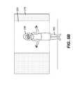
- FIG. 5 adepicts an object (person) within the projected beam prior to any image blanking being provided.
- FIGS. 5 b - hdepict different examples for blanking portions of the projected image during the presence of a detected object near the screen.
- FIG. 6 adepicts a subject individual who may be found in projection space.
- FIG. 6 bdepicts an ellipsoid human body model.
- FIG. 6 cdepicts a silhouette of a portion of a human body.
- FIG. 6 ddepicts the use of a human body model to identify a candidate head region.
- FIG. 6 edepicts a facial-feature modeling-construct having 82 facial feature points.
- FIG. 6 fdepicts a range of common human facial poses.
- FIG. 7depicts a prior art sensor for detecting bio-electric fields.
- FIG. 1a scenario is depicted in FIG. 1 in which a viewer 102 within a local environment 400 is observing an image that is projected on a screen 220 by a projector 200 that emits a light beam 210 .
- An intruding objectmay intercede between the projector 200 and screen 220 , such that all or a portion of the light beam 210 falls on the object, and all or a portion of the light beam 210 is then prevented from reaching the screen 220 .
- projector 200is a ceiling mounted long throw projector, in which the projector 200 is located a significant distance (for example >8 feet) from the screen 220 .
- the optical axis of the projectoris a distance “D” from the ceiling.
- the projection lens(not shown) can be used in an off axis situation to bias projection downwards relative to the optical axis.
- Various areas within the light beam 210can be at energy levels consistent with various laser eye-safety exposure levels, such as depicted in FIG. 1 , in which the beam volume proximate to the projector is Class 3B, while the beam volume towards the screen 220 is Class 3R.
- the current IEC laser classification standardscan be summarized as follows:
- While some laser-based image projection systemsmay operate with Class 2 ratings at the screen 220 , many systems will be designed with higher target power levels, whether to enable functional use when ambient light conditions are fairly bright, or to attain cinema-level illumination standards (16 fL), which will likely put them in the Class 3R category at or near the screen.
- the probabilities of eye-risk exposurescan be greatly reduced by the design of the viewing space and the use of physical or sensing barriers.
- design features and barriersmay not be present, while human (or animal) behavior can be fairly unconstrained, such that the probabilities of an object intruding into the beam are relatively high.
- the commonly assigned Agostinelli '039 patentprovides a projector 200 with a camera 310 that looks for an intruding subject (or object) 100 within the illuminating light beam 210 .
- the projector 200provides a projected image 215 on a display surface as a two-dimensional array of pixels.
- the projector 200internally has a laser light source, an image modulator for forming an image-bearing beam according to scanned line data, and projection optics for projecting the image-bearing light beam 210 toward the display surface.
- the camera 310obtains a sensed pixel array pattern by imaging the display surface (screen 220 ) with a two-dimensional sensor array.
- An internal control logic processorcompares the sensed pixel array pattern with the corresponding known image data on a frame-to-frame basis to identify image differences indicative of any portions of the image-bearing beam that are obstructed by an object 100 .
- the projector 200disables the obstructed portions of the image-bearing beam for at least one subsequent image frame.
- Agostinelli '039also provides motion tracking and outline sensing to determine how to provide further image blanking as the intruding object moves, and image filling or un-blanking in the regions vacated by the intruding object 100 .
- Agostinelli '039suggests that IR illumination and imaging can be used determine image blanking and image filling, using either passive (ambient or thermally emitted) or active IR light.
- Agostinelli '039also anticipates that face recognition or red-eye detection algorithms can be used to determine the location of the obstructing subject 100 , and thereby to block laser radiation to the area around the eyes of the subject 100 .
- face recognition or red-eye detection algorithmscan be used to determine the location of the obstructing subject 100 , and thereby to block laser radiation to the area around the eyes of the subject 100 .
- Agostinelli '039does not develop the use of either face detection algorithms or eye-detection algorithms in much detail. As a result, the suggested mechanisms for enhancing laser eye safety using such algorithms are not as robust as they can be.
- Agostinelli '039briefly cites prior art related to the detection of facial features or pattern features (such as the eyes), as well as red-eye detection.
- red-eye detectioncan seem like a useful attribute to target, as a human red-eye image is usually bright, saturated, and in high contrast to the surround.
- the presence of the red eye phenomena with human eyesis angle (or pose) dependent, iris (pupil) diameter dependent, and wavelength dependent, and thus may not provide reliable feedback for eye exposure.
- red eyegenerally occurs with flash rather than CW illumination, and thus may not typically occur when human eyes are illuminated by a projector 200 .
- red eye detection algorithmsare slow and not particularly suitable for real time image screening applications.
- the eye exposure laser safety standardsassume that the eye aversion response, which occurs in ⁇ 250 ms (or ⁇ 8 frames of exposure at standard video rates) will aid eye safety for human subjects exposed to Class 3B radiation.
- the intruding subject 100may choose not to look away, or may have a medically compromised eye aversion response.
- the eye damage a human viewer can incur from laser exposurecan also depend on the initial eye accommodation (optical power or focus), which also changes relatively slowly (over 500 ms) compared to the frame rate.
- the laser safety standardsare written assuming a human eye that may encounter direct laser exposure is daytime (or photopically) adapted.
- the human visual systemis capable of perceiving luminance levels in the range of about twelve orders of magnitude, spanning the photopic range (1 to 1 ⁇ 10 6 candela/m 2 ), the scotopic range (10 ⁇ 2 to 10 ⁇ 6 cd/m 2 ), and the intermediate mesopic range (10 ⁇ 2 to 1 cd/m 2 ).
- the eyewill adapt and can observe ⁇ 4 orders of magnitude of luminance simultaneously.
- Human dark adaptation to enhance dark visionis enabled by short-term biophysical phenomena, including opening or dilation of the pupil, biased usage of rods over cones, and increases in neural gain in the rods.
- the laser safety prior art and the laser safety standardsignore the problem of pet-eye exposure.
- common nocturnally-advantaged petssuch as dogs and cats have eyes with reduced color sensitivity but greater low light sensitivity than do humans.
- cat's visionis ⁇ 6 ⁇ more light sensitive than human vision, which may make cats' eyes more vulnerable to laser exposure damage.
- the increased sensitivityis enabled by the tapetum lucidum, a highly reflective membrane layer in the back of an animals' eye, located behind much of the retina.
- the tapetum lucidumincreases visual sensitivity basically by creating a double pass optical system, in which the rods and cones have two opportunities to absorb the incident light. The incident light that is not absorbed in either pass then basically retro-reflects from the eyes.
- the resulting eye-shinewhere the eyes to appear to glow, is an effect similar to the red-eye effect in humans, but with a greater color range (eye-shine can appear blue, yellow, or green, for example).
- Animal eye-shineis more frequently perceived than the photographic-flash-enabled red-eye effect in humans, but it also is an angularly sensitive effect (only detectable within ⁇ 15 degrees of eye normal). While cones are nominally located within a 10° radius corresponding to the fovea, rods extend out in significant quantities well beyond 40°.
- the angularly sensitivity for these phenomenameans laser light can enter and damage an eye, without either phenomena being detectable by a monitoring sensing camera 310 .
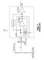
- the present inventionprovides a projector 200 (depicted in FIG. 3 a ) equipped with a computer 315 , image analysis means 360 , system controller 320 , and sensing means 305 .
- the projector 200comprises an assortment of optics 330 , including one or more light sources (lasers 332 ), image data modulators 334 , and a projection lens 335 , which provide an output image-bearing light beam 210 .
- the projector 200can utilize a variety of technologies to modulate the light, including micro-mirror arrays (such as the DLP device from Texas Instruments) or liquid crystal array devices (such as LCOS (liquid crystal on silicon) displays).
- micro-mirror arrayssuch as the DLP device from Texas Instruments
- liquid crystal array devicessuch as LCOS (liquid crystal on silicon) displays.
- linear array devicessuch as the grating light valve (GLV) or the conformal GEMS (Grating Electro-Mechanical System) device can be used.
- a scannersuch as a galvanometer or polygon is typically used to sweep image scan lines across the screen to form an effective 2D image.
- a scannersuch as a galvanometer or polygon is typically used to sweep image scan lines across the screen to form an effective 2D image.
- U.S. Pat. Nos. 6,411,425 and 6,476,848both to Kowarz et al. disclose imaging systems employing GEMS devices in a number of printing and display embodiments.
- the projector 200can also be a raster scanning system, where one or more laser beams are scanned across the display surface in a point-wise fashion.
- the image analysis means 360includes an obstruction analysis algorithm 365 , a feature analysis algorithm 370 , and a motion analysis algorithm 375 .
- datais collected by sensing means 305 (which is nominally one or more cameras 310 ) and provided to the image analysis means 360 (which is nominally an image processor) that analyzes the sensed data using various algorithms (including previously mentioned algorithms 365 , 370 , and 375 ).
- the computer 315can direct image blanking to occur, via system controller 320 and light blocking shutter 325 .
- projector 200can also include a monitor light source 307 that provides light, such as IR light for illuminating the monitored area 355 .
- monitor light source 307provides light, such as IR light for illuminating the monitored area 355 .
- FIG. 3 bshows aspects of the system configuration in greater detail
- FIG. 4outlines operational processes and logic the projection system 200 can use in sensing, assessing, and responding to intruding objects in the beam path.
- one or more sensors 305are used to examine a monitored area 355 that nominally includes at least the light beam 210 , the display surface 220 and a surrounding perimeter area.
- the method of the present inventionis best directed towards providing eye safety near the screen 220 , rather than in the Class 3b or Class 4 areas proximate to the projector.
- the blanking rules near the screen 220are more suitable for finessed decisions that provide eye safety while reducing viewer irritation.
- the blanking rulesare absolute (for example, blank image projection completely for any intruding object 100 , until the object is removed).
- the geometry requirements (short distances, wide angles) in this near projector regionmay not be particularly suitable for camera-based sensing.
- the monitored area 355 addressed by the present inventionmay not encompass the volume of the environment 400 proximate to the projector 200 where the light beam 210 is brightest.
- the monitored area 355is preferentially larger than the projected image size at the display surface 220 , thereby providing perimeter monitoring, which can allow the projector 200 to anticipate the presence of an intruding object 100 before it actually enters the light beam 210 .
- the projectorcan issue an alarm 327 , or characterize the object 100 to determine whether it is animate (living) or inanimate (non-living), human or animal, or determine anticipatory blanking, or analyze the object to identify and locate candidate head regions 245 , or prioritize some computational capacity for the object.
- Screen (or display surface) 200can reside in a plane, or be curved, or comprise a more complex 3D shape. As a generalized display surface 200 , “screen” 200 can simple be a section of wall, for example.
- the projection monitoring geometrycan be well served by camera-based sensing means 310 and image analysis means 360 .
- Camera(s) 310can be a fixed focus lens (including hyperfocal), a fish eye lens (with a field of view, short focal distance, but much distortion), or a zoom lens, or provide stereo capture, and capture visible or IR light.
- the sensing means 305can include other sensing technologies, such as EM-bio-field detection, microwave, or ultrasound based intruder detection.
- FIG. 4depicts an exemplary object exposure management process flowchart 500 that illustrates processing that the present invention can implement in sensing, assessing, and responding to intruding objects 100 in the beam path 210 or in the monitored area 355 .
- the light exposure management process 500includes an initial object detection and location step 510 in which a motion analysis algorithm 375 and an obstruction analysis algorithm 365 analyze sensed data collected from the monitored area 355 .
- an alarm 327can be provided.
- the projection environment 400can include numerous objects, including innocuous objects 100 , such as a vase that is sitting motionless on a shelf near the edge of the screen 220 , various testing methods, including use of reference images, motion analysis to look for moving objects, or detection methods that identify and localize animate (alive) objects 100 , can be used to distinguish between innocuous objects 100 and objects that represent at least an initial exposure concern.
- innocuous objects 100such as a vase that is sitting motionless on a shelf near the edge of the screen 220
- various testing methodsincluding use of reference images, motion analysis to look for moving objects, or detection methods that identify and localize animate (alive) objects 100 , can be used to distinguish between innocuous objects 100 and objects that represent at least an initial exposure concern.
- the projection system 200can remain in a watchful state, relative to that object, until the object leaves the monitored area 355 , or enters the light beam 210 (thereby likely requiring a system response), or is determined to be completely innocuous.
- the projection systemdetermines an initial image blanking (step 520 ).
- the initial image blanking step 520can use the obstruction analysis algorithm 365 to quickly determine the size and location of the object 100 and then define an initial image blanking that at least encompasses the object 100 .
- the initial image blanking originating with step 520is then enacted via apply blanking step 525 using system controller 320 .
- active monitoring and tracking of the object 100continues via step 540 using motion analysis algorithm 375 , to enable ongoing image blanking.
- an object feature analysis step 545uses sensed data or a feature analysis algorithm 370 to find features that enable an object classification (step 500 ).
- an object 100can be classified using image analysis algorithm 360 as animate (alive) or inanimate (not-alive). In the latter case, following the object animate test step 575 , the initial image blanking can be removed or altered (via step 530 ) using system controller 320 , perhaps with an accompanying warning or alarm. More generally, for example, an object 100 can be classified as human, pet, cat, dog, or as a moving inanimate object.
- object monitoring and trackingwill continue step 540 , thereby enabling continued image blanking and further object feature analysis using feature analysis algorithm 370 to locate candidate head regions 245 , eye features, or other salient object attributes, as shown in step 555 .
- head monitoring regions 235 and a refined image blankingcan be determined. If the object is still inside the projected area (tested at step 570 ), then the refined image blanking can be provided (step 525 ), and object monitoring can continue (step 540 ).
- a monitor and tracking loop, targeting monitoring and image blanking to candidate head regions 245 using head region blanking 240can then be maintained until the object 100 leaves the projected image area.
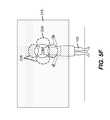
- image blankingcan span a range of blanking options, including large blanked areas ( FIGS. 5 b and 5 c ), general torso area blanking ( FIG. 5 d ), or silhouette blanking ( FIG. 5 e ), before attaining head region blanking 240 ( FIG. 5 f or FIG. 5 g ), or inanimate object ( 100 a ) object exposure ( FIG. 5 g ).
- the object exposure management process 500can provide object detection for stationary objects that are present at turn-on, and not just objects 100 that move into the monitored area 355 or projected light beam 210 during image projection.
- the initial object detection and location step 510can search for objects 100 using visible or infrared imaging, reference images, EM field sensing, ultrasound, or other means, to detect and locate objects 100 , and preferably characterize them as animate or not.
- Some objects 100can also be tagged as “status uncertain”. If these objects are outside the projected image area 215 , the system 200 can simply tag them for monitoring until at least their status become clear or they are removed.
- reference imagesare images of the monitored area 355 that are acquired prior to image projection. These images can be acquired using visible or IR light or both. A new reference image can be compared to a prior reference image that may have been acquired the last time the projection system 200 was operated, as an aid to recognizing static inanimate objects 100 .
- image blankingis intended to describe an image area in which the light beam 210 for the blanked region is effectively off, and image light from the projector 200 does not enter that area. Alternately, blanking can still allow image light to be directed to the designated eye-safe areas, but with the light intensity reduced to safe eye exposure levels (nominally Class 2 or less).
- FIG. 5 adepicts a situation in which a subject 100 is within the projected image 215 , but blanking has not yet occurred. Under these circumstances, a range of blanking options exists. As a first example, the entire image-bearing light beam 210 can be blanked, such that projector 200 does not illuminate the display surface 220 with a projected image 215 until the object (obstruction) 100 is removed.
- FIG. 5 bdepicts a second option for blanking, in which the projected image is blanked for the width of the object 100 (with margin), and the height of the screen 220 , providing a blanked image portion 225 .
- FIG. 5 cdepicts a third option for blanking, in which the projected image 215 is blanked to create an area of blanked image 225 defined by the width and height of the object 100 m (with or without margin). Whether the entire screen is blanked, or the partial screen blanking options of FIG. 5 b or 5 c are applied, as significant areas of the projected image 215 , beyond those occupied by the object itself, are blanked, viewer annoyance can increase.
- FIG. 5 ddepicts a fourth blanking option, in which the body shape of a person or animal (object 100 ) must be sufficiently understood to allow some innocuous portions, such as outstretched limbs, to be illuminated, while generally blanking image projection to an expanded torso area (including the head).
- FIG. 5 edepicts a fifth blanking option, in which the sensed image of the intruding object 100 is analyzed to find an outline, and then the outlined area, or an expansion thereof to provide margin, is then blanked, effectively creating a blanked object silhouette 230 . This is similar to the outline image blanking discussed in the commonly assigned prior art Agostinelli '039 patent.
- FIG. 5 ddepicts a fourth blanking option, in which the body shape of a person or animal (object 100 ) must be sufficiently understood to allow some innocuous portions, such as outstretched limbs, to be illuminated, while generally blanking image projection to an expanded torso area (including the head).
- FIG. 5 fdepicts a sixth blanking option, in which head region blanking 240 is applied, and associated head monitoring regions 235 are identified.
- the head region blanking 240is applied relative to a human subject 100
- FIG. 5 gdepicts head region blanking applied to an animal (object 100 b ).
- torso blankingFIG. 5 d
- silhouette blanking 230 or head region blanking 240represent refined image blanking with less image area being lost for the viewers.
- the lost image areais smaller, the risks of subsequent eye exposure are potentially higher.
- the image blankingbecomes increasingly tighter around the intruding object 100 , the accuracy of the image screening methods to locate and track head or eye-regions are increasingly pressured to enable a compensating eye exposure risk reduction.
- an intruding object 100when an intruding object 100 is located within the light beam 210 , a range of blanking options are available. In many instances, it can take time (for example several frame times) to obtain a conclusion with high confidence that an intruding object is animate (alive) or inanimate (not-alive), and in the former case, to then localize body shapes, then head regions, and finally eye regions. Therefore, it can be preferable to provide an initial blanking (step 520 ) in response to the presence of an intruding object 100 that is significantly oversized, such that accidental eye-exposure is highly improbable.
- an initial blankingcan blank the entire screen, or span the screen height and object width (as in FIG. 5 b ), or span the object's height and width in the projection space ( FIG. 5 c ).
- a smaller initial blanking, as in FIG. 5 c or FIG. 5 dis likely preferable from the viewers point of view.
- the blankingcan be relaxed (step 575 , allowing illumination of inanimate objects (object 100 a in FIG. 5 g )) or tightened (step 535 , to blank only silhouettes ( 230 in FIG. 5 e ) or head blanking regions 240 ( FIGS. 5 f and 5 g ).
- a variety of sensing and analysis methodscan potentially be used to screen for animate objects 100 , object silhouettes 105 , head monitoring regions 235 , candidate head regions 245 , faces, or eyes.
- a variety of screening methodsare required to robustly reduce eye exposure risk.
- detection and characterization of body shapes or silhouettes 105followed by localization of candidate head regions 245 and head monitoring regions 235 are useful.
- the candidate head regions 245are the identified areas where image analysis determines that one or more heads are likely located.
- the body shape analysiswill yield one candidate head region 245 per body shape, but if the shape is sufficiently complex or atypical, the uncertainty may result in multiple candidate head regions 245 being identified, although continuing analysis may resolve the uncertainty.
- this uncertaintycan mean that image projection to several candidate head regions 245 for a body shape, or to all or most of the body, is blanked because the uncertainty is unresolved.
- feature analysiswill identify one candidate head region 245 per body 120 or body shape with high certainty.
- the candidate head region 245is tagged to be blanked, thereby defining a head blanking region 240 .
- the head region blanking 240( FIG. 5 f ) should be over-sized (for example, by 40%) relative to an associated candidate head region 245 , to provide margin, reducing risk relative to sudden head movements.
- the oversized head region image blanking 240 around the intruding subject 100may appear as a bubble or halo around the head, against the backdrop of image projection to the rest of the screen 220 .
- Identification of a candidate head region 245also can lead to determination of head monitoring regions 235 associated with that candidate head region 245 .
- the head monitoring regions 235represent the likely image areas where a candidate head region 245 or a blanked head region 240 can be in a subsequent time as the object (person or animal) moves. Computing power can then be prioritized to identify subsequent head motion into a head-monitoring region 235 as the subject moves, so that head blanking regions 240 can be shifted accordingly in a rapid manner.
- the use of head monitoring regions 235is closely coupled to motion detection and motion tracking (via motion analysis 375 ) of the object 100 .
- Subject movementcan be measured using a subject movement factor that tracks the speed, range, and frequency of subject motion relative to an area, which can be the overall monitored area 355 or a body shape area (for example).
- Information regarding patterns of body movement for typical intruders such as people or catscan also be used to define and prioritize the head monitoring regions 235 .
- a series of head monitoring regions 235are shown around the blanked head region 240 of FIG. 5 f .
- the application (size and positioning) of head region blanking 240 and head monitoring regions 235can be biased in the direction subject movement.
- the eye exposure probabilityis then higher to the left than right.
- the head region blanking 240can extend more to the left than right, and emphasis on head position monitoring using head monitoring regions 235 can favor the left.
- the head blanking region 240 and head monitoring regions 235can also be larger for moving subjects 100 , as compared to more stationary subjects.
- the application of head region blanking 240 and head monitoring regions 235can also be different for animals, as compared to people. For example, as animals, such as cats or dogs, can both move faster and more unpredictably than people do, larger areas of the projected image can be blanked on a percentage basis when an animal is passing through the projected beam near the display surface 220 . Subject movement through the display area may be so rapid that the projection system may simply have to default to large area blanking (such as FIG. 5 b ) until the subject leaves or settles.
- head monitoring regions 235 or head region blanking 240depends largely on subject movement, and secondarily on subject type (person or animal). Other secondary factors, such as activities lumping, for example), or gestures, may impact their use. While the identification of candidate head regions 245 , and then head monitoring regions 235 can support head region blanking 240 ( FIG. 5 f ), these techniques can also be used for other tight image blanking approaches, including silhouette blanking 230 ( FIG. 5 e ) or torso area blanking ( FIG. 5 d ). Of course, as the speed and accuracy of the analysis algorithms improves, initial head blanking regions 240 can potentially be tighter around the heads 125 of intruding objects 100 .
- confidence valueswhich are measures of the confidence assigned to the value of an attribute, and which are often expressed as a percentage (0-100%) or a probability (0-1), can be calculated to indicate the likelihood that a given image area contains a candidate head region 245 .
- both initial image blanking and tightened image blankingshould be oversized relative to at least candidate head regions, if not body-shapes. It is also important to minimize false positive test results, that can cause either safe obstructing objects or non-objects (such as projected image content) to be identified as an intruding animate object with a head or eyes, as such identifications can cause image blanking un-necessarily. Additionally, in the case that the projection system 200 first identifies an intruding object 100 as having a candidate head region 245 , and then subsequently determines otherwise (that the intruding object is inanimate), then warning alarms 327 can be provided before any related image blanking is disabled.
- the eye-safety value associated with a projector 200 of the present inventionis highly dependent on the robustness of the intelligent sensing used to locate and assess intruding objects as animate, while identifying head regions thereon.
- a variety of techniquescan be used for identifying or extracting features from the sensed image data, with associated advantages and disadvantages (also summarized in Table 1).
- Most of the techniques discussed beloware focused on intelligent sensing using data collected with camera-type sensing devices 310 that can use visible or IR light.
- algorithms within the image analysis means 360enable these techniques, as represented by an obstruction analysis algorithm 365 , a feature analysis algorithm 370 , and a motion analysis algorithm 375 .
- the obstruction analysis algorithm 365basically determines the location, size and shape of an obstruction.
- the feature analysis algorithm 370determines head, facial, or eye features that blanking and monitoring can target. These image analysis algorithms also preferably determine whether the obstruction (object 100 ) is animate (alive).
- a range of image interpretation algorithms or techniquescan be used for obstruction analysis or feature analysis, depending on the available sensed data, object characteristics, and processing limitations.
- a sensing camera 310detects images of the screen 220 and any intervening intruding objects 100 .
- image difference comparisons of the sensed image to the projected imagewill appear as image distortions or brightness variations.
- Image difference analysiscan provide an outline or silhouette 105 of the intruding subject 100 (see FIG. 6 c ), to enable silhouette-blanking 230 (see FIG. 5 e ).
- the derived outlinescan also be used as input data for body shape analysis, to identify the type of object 100 as human or animal, and to locate candidate head regions 245 and head monitoring regions 235 .
- This comparative image difference analysiswhich can be included in the obstruction analysis algorithm 365 , uses image correlation and mutual information calculations, can be robust and quick enough to operate in real time. While the use of the projected image as a reference reduces content confusion (interpreting a projected image of a person as a potentially intruding subject 100 ), this approach still has content dependence. For example, if an image of a face is projected onto an intruding person's head, the image differences detected by the camera 310 can be reduced, making determination more difficult. Individually, the risk that the image difference method fails to detect the intruding person may still be small, but other aspects of the scene content may add further difficulty.
- the present inventionprovides for a projector 200 that targets the detection and tracking of head regions.
- Intelligent sensing of body shapes, head regions, and facial featurescan use visible spectrum images and image difference analysis, but IR images can be helpful because they are readily distinguished from the projected image content.
- IR imagingcan be used both for body-shape and facial feature imaging.
- NIRnear-IR
- key human facial featureshair, skin, and eyes, for example
- look differentdarker or lighter, etc.
- IR imagingvia IR imaging, valuable data can be obtained to generally localize and size an intruding object, for large area blanking ( FIGS. 5 b and 5 c ).
- IR imagingcan also be readily used to outline a body shape to determine a silhouetted 105 used in silhouette blanking.
- knowledge of the IR imaging characteristics of skin, hair, eyes, or other featuresmust be properly accounted for to achieve a successful result.
- a sensing camera 310(see FIGS. 3 a and 3 b ) can be placed in a position offset from the projection axis of projector 200 .
- the camera 310can image the shadow 110 cast by light beam 210 passing around the intruding object 100 .
- the shadowswhich are present with high contrast against the surrounding projected image 215 , can be detected by a fast (real-time) screening algorithm.
- the projected image contentincludes large dark areas adjacent to, or overlapping the intruding object, shadow-based object detection can be compromised.
- this methodrequires one or more sensing cameras to be positioned at sufficiently offset angles from the projector optical axis that shadows can be reliably and sufficiently seen.
- Physical or social limitationscan prevent the needed camera placements. While the use of IR cameras and light sources can remove the image content confusion problem, limitations in camera and light source placement relative to the projector 200 and screen 220 still can limit the reliability of this technique.
- shadow imagerymay be particularly insufficient for understanding physical body positioning and locating candidate head regions 245 .
- screening for intruding objects 100 based on shadow or silhouette analysislikely as an aspect of the obstruction analysis algorithm 365 , can be useful, but it is not likely a sufficient screening method onto itself.
- screening sensed images based on body shape characteristicscan be highly useful for distinguishing between animate and inanimate objects, distinguishing between people and animals, and then in locating candidate head regions 245 on the body shape of the identified animate objects.
- An outline of the body shapecan be obtained by the image difference analysis and shadow analysis methods discussed previously, or by direct imaging of the body shape with visible or IR light.
- body modelscan include more information than just outlines, including textures and recognition of joints or articulating limbs to aid identification. Body models can be understood using the illustrations of FIGS. 6 a and 6 b .
- FIG. 6 adepicts a subject 100 who has a physical body 120 including various limbs, a torso, and a head 125 , with a face 130 having eyes 130 , mouth 140 , and nose 145 .
- FIG. 6 bthen illustrates a simplified body model 265 in which the torso, limbs, and head are represented by a series on interconnecting body shape ellipses 270 .
- FIG. 6 ethen depicts face point model 90 which can specifically be used for detection or recognition of faces 130 .
- Body shape detection and/or recognitioncan then be used to determine silhouettes 105 for silhouette blanking 230 ( FIG. 5 e ) or torso sizing for torso blanking ( FIG. 5 d ), or to identify subjects as people or animals, or to locate candidate head regions 245 and determine head region blanking 240 and head monitoring regions 235 .
- various techniquesexist for representing human or animal body shapes, which can be applied to identifying intruding objects 100 as animate and human or animal. Confidence values can be determined from body shape data as to whether an object is a person or animal, or even the type of animal. These techniques basically use body shape models or templates, identifiable to various common forms such as people, cats, dogs, or horses. Inherently, these models lead to localization of candidate head regions 240 in the observed body model 265 . These algorithms tend to become more accurate in identifying and tracking body shapes when other data, such as appearance data (color, textures, or features) or motion data are also used.
- body shape modelingcan be very useful for quickly determining that an object 100 is likely animate (alive) or not (step 575 ). Body shape modeling can then also be used in locating candidate head regions 245 (step 555 ).
- body shape detection algorithmswhich can be part of the obstruction analysis algorithm 365 , can be useful in enhancing eye safety for a projector 200 , they also are not sufficient, and body shape screening is best used in combination with other techniques. Also, in the case that IR imaging is used, the algorithms would have to be adapted to handle the appearance differences that occur in IR images, as discussed previously.
- imagescan be screened to locate people or animals directly without first finding body shapes.
- the paper Putting Objects in PerspectiveD. Hoeim et al., published in the IEEE Proc. on Computer Vision and Pattern Recognition (CVPR) 2006, pp. 2137-2144, describes an approach for person detection which is based on knowledge or estimation of the camera viewpoint and estimation of the rough surface geometry in the scene to define the probability of locating a person in a given image location.
- CVPRComputer Vision and Pattern Recognition
- This kind of techniquecan be used to quickly assess the sensed images to localize likely intruder locations, and then other techniques, such as body shape model analysis (discussed above) or direct head or facial feature screening analysis (discussed below) can refine the analysis. While “subject-in-box” searching does not search for obstructing objects directly, this technique can be included in the obstruction analysis algorithm 365 .
- body shape analyses with IR or visible imagingwill quickly and robustly identify the candidate head region 245 of the intruding subject 100 without necessarily there being a need for further analysis.
- Image difference analysis using visible light imagescan also localize candidate head regions fairly robustly, but image content and image blanking impact the technique.
- person-in-box analysisusing either visible or IR images
- it is desirable to refine or validate analysis of candidate head regions 245even in the case of a body shape analysis that has high certainty of head localization.
- Headscan be located in images using a variety of techniques, including analyses using skin color areas, hair appearance, and head, face, or eye based facial features or templates. In the case of the present invention in which eye-safety is a concern, it is not necessary to recognize or identify the intruding subjects 100 by name. In particular, it is a goal of the present invention to locate candidate head regions 245 , and then provide head region blanking 240 while tracking movement to head monitoring regions 235 .
- the greatest risk related to intense light eye-exposurecorresponds to frontal view head poses, rather than side or rear views.
- eye damagecan potentially occur for a significant range of side views, ranging between frontal and 3 ⁇ 4 frontal poses (see FIG. 6 f ), depending on eye direction.
- head posecan change quickly, pivoting eyes that were previously looking away suddenly towards the projection system. Therefore, it is preferable to use algorithms that quickly and robustly identify head regions, whether eyes 135 are actually detected or not. While sensed images can be searched directly to locate head regions, without first finding likely image regions using body shapes, image differences, or person-in-box analysis, the image analysis time can increase significantly when the entire sensed image must be examined for head or facial details.
- an analytical techniquethat analyzes images to look directly for nominally circular skin-toned areas can be used.
- the algorithmcan analyze for color data that is common to skin tones for all ethnic groups, thereby reducing statistical confusion from racial, ethnic, or behavioral factors.
- the paper Developing a predictive model of human skin colouringby S. D. Cotton (published in the Proceedings of SPIE Vol 2708, pages 814-825, 1996) describes a skin color model that is racially and ethnically insensitive.
- this techniquecan be used to localize or confirm candidate head regions 245 in image areas previously assessed by the previously discussed image difference, body shape, or person-in-box methods. Again, as this approach uses visible light, the projected image content can confuse this analysis.
- projector 200is a laser based projector, as the three laser spectra, each of which likely has a narrow spectrum ( ⁇ 5 nm), can be removed by filters within the sensing camera, leaving images derived only form the ambient visible light. While this analytical technique can be fast, directional variations in head pose, including poses dominated by hair, can complicate the analysis. Additionally, this technique does not help with animals.
- texture based modelingsuch as hair-model screening algorithms can be employed.
- hair-model screening algorithmsFor example, the paper “ Detection and Analysis of Hair ”, by Y. Yacoob and L. David, which was published in IEEE Trans. on PAMI, Vol. 28, pp. 1164-1169, 2006, describes a person-recognition appearance model based on the texture and shape of facial or head hair.
- an algorithm of this typecan presumably be simplified and operable with IR images, as well as visible light images.
- this type of algorithmcan be adapted to assist in the detection of animal fur, and may have value in tracking fur color patterns.
- This methodmay or may not be particularly useful in distinguishing head fur from fur associated with other body areas.
- texture based modelswhich key typically on features with high spatial frequency and variable contrast differences, are usually slow algorithms.
- the projection system 200can also learn to recognize subjects 100 (particularly animals) that have pronounced physical attributes, such as pattern of fur coloring that is easily recognizable.
- the system 200can be presented with reference image data for a household pet, or simply see the pet on an ongoing basis, and a model or templates can be developed to enable rapid searching for that pet.
- FIG. 6 edepicts the facial features used in the Active Shape Model (ASM), which is a facial model useful for recognizing people in images.
- ASMActive Shape Model
- the ASMwhich is a 2D facial model with faces described by a series of facial feature points, was described in the paper “ Active shape models—their training and application ”, by T. F. Cootes, C. J. Taylor, D. Cooper, and J. Graham, published in Computer Vision and Image Understanding 61, pp. 38-59, January 1995.
- the facial active shape modelwas subsequently expanded to comprise the collection of facial feature points (1-82) depicted in the face point model 90 of FIG. 6 e .
- Localized facial featurescan be described by distances between specific feature points or angles formed by lines connecting sets of specific feature points, or coefficients of projecting the feature points onto principal components that describe the variability in facial appearance. It should be understood that there are a variety of facial recognition modeling approaches that have been developed for enabling the recognition of people in pictures, including the eigen-face model, the active appearance model (AAM), and 3D or composite facial models.
- AAMactive appearance model
- the face point model 90 of FIG. 6 eprovides a basis for understanding face detection.
- Many face detection algorithmssearch for key facial features, such as the eyes ( 135 ), mouth ( 140 ), and nose ( 145 ) that have physical prominence, and can be further accentuated by shadowing.
- These key facial featurescan be modeled with a reduced set of facial feature points (8-20 points) or with templates (representing the eyes-nose-mouth) for example.
- Other templates or simplified facial models based on key prominent featurescan be used.
- searches that look for shadow-highlight-shadow patternscan be used.
- a horizontally arrayed shadow-highlight-shadow patterncan correspond to how the eye-nose-eye human facial features typically appear in images relative to contrast geometry.
- Dowdallsuggests that under IR illumination, templates that model eyebrows and eyes are useful because of the pronounced image contrast.
- human facescan also be located and tracked with algorithms that localize to the eyes and mouth.
- facial detection algorithmscan search quickly for prominent facial features, such as eyes, nose, and mouth, without necessarily relying on body localization searches first. However, these algorithms are then prone to false positives, identifying clocks or portions of textured wall surfaces as having the sought facial features. Also most facial detection or facial recognition models, except the 3D composite models, are 2D models that function well in examining frontal (or direct-on) facial images, but which fail at increasing rates as the head pose becomes more and more of a side view (see FIG. 6 f ). For the present invention, facial detection models that can also find side profile views are particularly useful. Any of these various algorithms for finding heads or faces, as well as others not mentioned, can be aspects of the feature analysis algorithm 370 .
- a search process based on head shape templatescan be used to locate and track candidate head regions 245 .
- the head shape templatescomprise sets of head and facial outlines for different poses, in which features such as the chin, mouth and lips, nose, eyes, forehead, ears, or hairline become detection attributes. While the set of templates can be fairly large, each involves minimal data. Statistically derived ground truth head shape templates spanning the range of poses can also be used. Accuracy is likely reduced as head poses of an intruding subject 100 have the individual looking at the screen 220 instead of the projector 200 , meaning that the back of the head is visible to the camera 310 . However, while this is a plausible search approach for humans, the range of pose variations with animals can reduce the value of head shape templates in analyzing their sensed images.
- locating eyes 135can be used to validate a prior identification of a candidate head region 245 . Additionally, in instances in which confusing images have caused multiple candidate head regions 245 to be identified for an apparent body shape or area, eye detection can clarify the determination, enabling head region blanking 240 and head monitoring regions 235 to be refined.
- Eye searchingcan be performed using the associated facial feature points (points 1 - 22 ) of the face point model 90 ( FIG. 6 e ).
- points 1 - 22the facial feature points of the face point model 90
- that approachinvolves more detail (finding the iris, pupil, eye corners, for face recognition tasks) and search time than is preferred for the present invention.
- algorithmscan perform image search tasks for eye features using eye-specific deformable templates, such as suggested in the paper “ Feature extraction from faces using deformable templates ”, by A. L. Yuille, P. W. Hallinan, and David S. Cohen, published in International Journal of Computer Vision, Vol. 8, pp. 99-111, 1992.
- the deformable templatescan describe the generalized size, shape, and spacing of the eyes.
- eye-shineis angularly sensitive, and eye damage could occur without eye-shine being visible, in the circumstances of greatest risk in which a pet stares back at the projector, eye-shine can be highly visible. Due to the high brightness or high contrast of the eye-shine eyes relative to the surround, it can be easier and quicker to find eyes exhibiting eye-shine than to search for candidate head regions first. In such circumstances, eye-safety can be enabled by detecting eye-shine eyes in the image, and then blanking image projection with margin around the area the eyes reside in.
- Body Image Visible Speed & Confusionwith areas differences robustness projected image & adjacent image content, reduced signal during blanking Body Shadows Visible, Speed, high Camera & light areas IR contrast source images to placement, process indistinct body shapes, projected content confusion (visible) Body Torsos or Visible, Directly finds Speed, body areas body IR silhouettes and shape shapes, head regions, complexity & body identifying variation, models animate sensitivity to objects, can obscuration use motion data Body Person- Visible, Speed Indirect, areas in-box IR uncertain adaptability for home behaviors and pets Heads/ Skin areas Visible Speed Humans - faces pose & hair sensitivity, confusion with projected image, not applicable for pets Heads/ Hair Visible, May help Speed, pose faces IR reduce pose sensitivity sensitivity and with animals Heads/ Facial Visible, Speed (for Potential for faces features/ IR template false positives, face models models) pose sensitivity, & templates adaptability to pets Heads/ Head shape Vis
- the sensors 305 provided with projector 200include only IR sensitive cameras, and not visible light sensitive cameras, then both body-shape and person-in-box analyses can be used concurrently.
- both image difference and body-shape analysiscan be used concurrently.
- localization of body shapeswould require only one image analysis search and feature extraction analysis method, which would preferably be body-shape analysis, as it leads directly to the fundamental information (identification of head regions 245 ) that is sought.
- the sensed image data, and particularly the localized body areas therein,can then also be analyzed to localize candidate head regions 245 and head monitoring regions 235 therein.
- one or more of the described methods for localizing heads and faces that are listed in Table 1can be used, depending on whether the sensing cameras distinguish visible light, IR light, or both.
- an image search approach based on head shape templates or prominent facial feature templates that locate eyes or nose or mouth (or eyebrows) for examplecan work, and likely provide the most benefit if they are used concurrently.
- an image search approach based on head shape templates (or head features) and eye shinecan provide substantial benefits if used concurrently.
- at least one of the preferred methods for localizing heads, faces, or eyesis nominally used in combination with at least one method for localizing animate bodies, as the combination enhances robustness and reduces computation time.
- the present inventionanticipates that head or face targeted intelligent sensing will analyze image data with a combination of image interpretation methods so as to localize body positions and head or face regions thereon.
- multiple analytical techniqueswill be used for locating both animate bodies and the heads (or faces) thereon.
- image interpretation technologiesimproves, the performance of the analytical methods described above may improve, or new analytical approaches or algorithms may emerge.
- appropriate algorithmscan be optimized, combined, or developed with this particular application in mind.
- computer 315within projection system 200 , includes an intelligent agent or artificial intelligence (AI) or set of algorithms that adaptively respond or anticipates object motion, and modifies the image blanking accordingly.
- This intelligent agentcan also be a learning system that progressively gains understanding of user activities and communication needs.
- animate objectshave been defined as objects such as people or animals that are alive.
- objects 100 a and 100 bare intruding into the projected image 215 .
- Object classificationfor example using images and body shape analysis, can classify object 100 b as a cat, and initiate head region blanking 240 .
- Object 100 acan be classified as an inanimate (not alive) object, and the projected image can be allowed to impinge on it.
- FIG. 5 hdepicts several examples in which an intruding object 100 is a moving non-alive object.
- Object 100 bis a floating balloon on which the projected image 215 is being allowed to impinge.
- Object 100 cis a floating balloon that has a face 130 illustrated on it, and for which the image analysis algorithms of the present invention can identify a candidate head region 245 and head region blanking 240 . Confusing circumstances such as the balloon with a face 130 can result in no image blanking (like object 100 b ), head region blanking 240 (like object 100 c ), or oversized image blanking 225 .
- image analysis algorithmscan often correctly identify an object 100 as an animate object.
- Object motion dataprovided by motion analysis algorithm 375 , including motion tracking data, motion frequency data, or characteristic motion data (such as movement or articulating limbs) can all aid a successful determination.
- object motion data and analysiscan complement the feature-based image analysis approaches by providing supporting data.
- analysis of object motion datacan potentially detect and locate a human or animal based on characteristic motion data more quickly than does feature based analysis.
- initial image blankingcan be triggered by motion analysis.
- thermal IR imagingwhich utilizes the fact that people and animals are ⁇ 300K blackbody sources, can also be used to detect whether an object is animate or inanimate, provided that the ambient temperature of neighboring inanimate objects is sufficiently below 300K.
- thermal cameras ( 310 )are presently too expensive for consumer applications.
- a laser projector 200when first turned on, it typically needs to be calibrated. This can be done using a camera 310 which first locates the edges of the projected image 215 on the screen 220 , followed by remapping of the camera pixels to the image projector pixels and then determining relative light levels of each pixel for a uniform illumination levels and adjusting them accordingly to obtain a uniform response function over the entire screen area.
- the first projected imagecan be provided at a low light level that is eye safe. In the case that no obstruction is detected in the screen area of the image there is no problem and the light intensity could be increased safely for calibration while detecting for an obstruction coming into the beam area.
- the reflected light from an object 100 that is occluding the light beam 210will in general be different from that reflecting off of the projection screen 220 and deviations from the mean value can be used to determine locations of the blocking object 100 .
- projection errors that provide calibration differencescan be expected to be relatively small between multiple adjacent pixels, and they will tend to have the same localized mean value, whereas the detected reflected signals from obstructing objects 100 will be distinct from the expected mean value.
- extended areas of large deviation from the meancan be used to indicate obstructions, and data from these regions need not be used for calibrating the projector 200 .
- the data used for calibration in the obstructed area of the displaycan be calculated from mean of the region in the external vicinity of the obstruction.
- the vacated regionscan now be calibrated as before.
- the camera exposure timesneed to be short enough that obstruction detection can occur while avoiding the possibility of eye damage.
- Calibration imagescan be acquired during multiple short exposures, and then combined to provide the calibration data for adjusting individual display pixel light levels.
- a line scanned systemsuch as a GLV based projector 200 , as described in U.S. Pat. No. 7,144,117 by Kojima et al., or a GEMS based system 200 described in commonly assigned U.S. Pat. No. 6,422,425 by Kowarz et al.
- a one dimensional modulator array334
- each pixelcan still be calibrated when an obstruction is present by using the data from the non-obstructed regions corresponding to that pixel.
- the projection system 200 of the present inventioncan be equipped not only with cameras 310 , but one or more sensors 305 that provide non-camera type sensing.
- computer 315also provides appropriate data processing beyond just image analysis and processing 360 to analyze this data.
- non-optical imaging technologiesthat enable quick detection and localization of animate objects, and perhaps candidate head regions 245 thereon, are particularly valuable.
- microwave, ultrasound, or acoustic (voice) sensingcan be used as first such examples of a non-imaging alternate sensor 305 .
- motion-detection monostatic microwave sensorswhich provide both the transmitter and receiver, can be tuned to measure the Doppler shift for the frequency range of 20-120 Hz, in which human movement generally falls.
- Doppler microwave sensors working at 24 GHz CWcan also be used to detect moving objects 100 . Objects that fail to produce signals outside these ranges can potentially be ignored.
- Pulse echo ultrasoundcan also be used to detect obstructing objects 100 and to determine their distance from the source (at projector 200 ).
- Doppler motion detectorsrely on the mechanism that a moving reflector (object 100 ) causes a phase difference between the transmitted and the received reflected signal. These detectors can be used in a continuous wave mode. Ultrasonic waves can be readily transmitted through air in the 40-60 kHz frequency range. A combination of CW and pulse echo can be used to determine if there is an obstructing object 100 , as well as its distance from the source, and then if it is moving.
- Doppler and ultrasoundcan be used simultaneously to improve sensitivity and reduce false alarms.
- An example of combining microwave and ultrasonic sensors for motion detectionis described in the paper “ Highly sensitive motion detection with a combined microwave - ultrasonic sensor ”, by H. Ruser and V. Magori, published in Sensors and Actuators, Vol A 67 p 125-132, 1998.
- moving inanimate objects 100such as curtains moved by room fans or a moving remote control car, can cause false positives for Doppler-based motion detection schemes.
- itcan still be desirable to combine microwave and/or ultrasound sensing with imaging based sensing or other sensing modalities. Combining two or more of these technologies in a sensing system and using an AND gate can help reduce false positives.
- FIG. 7depicts a block diagram of a typical electric potential sensor 300 showing the probe electrode and the feedback, guard and input bias circuits of the electrometer amplifier.
- This electro-dynamic sensor ( 300 )measures a displacement current i d , which is actually a rate of change of voltage measurement, with a high impedance circuit.
- the deviceconceptually acts as a perfect voltmeter that is able to measure very low, bioelectric potentials, including various bio-electric signals such as ECGs, EEGs and EOGs.
- ECGelectrocardiogram
- EEGelectroencephalogram
- EOGelectro-oculogram
- the EOGis also a weak signal that measures the resting potential of the retina, while being sensitive to both eye blink and eye motion. As with the EEG, a direct measurement of EOG signals can likewise be useful for locating eyes for the present application.
- multiple bio-electric field sensorscan be used to localize animate objects within a space.
- ECG signalscan be used to first localize body position, and then EEG or EOG signals, to localize head positions.
- EEG or EOG signalsFor this type of application, it is not necessary to attain medical quality signals supportive of diagnostic analysis, but lesser quality signal sufficient to localize and distinguish such signals from multiples sources (objects 100 ) would suffice.
- the resulting datacan be used in combination with image-based detection to determine if an intruding object 100 is animate or not, thereby reducing false positives or uncertain results (object 100 is a stuffed animal).
- a bio-electric field sensing technologycan also be used to directly detect and locate heads.
- head size informationand therefore the size of head region blanking 240 , may not be determined directly by this type of technology.
- the combination of bio-electric field sensors and imaging devicescan provide a very effective combination to identify animate objects quickly and robustly, and then derived the needed shape and sizing information. If image-based data is not available, other sizing data or metrics may be required.
- bio-magnetic field sensing(or more generally, bio-electromagentic field sensing) can also be used for the purpose of animate object detection.
- the apparatus or methods described hereincan be embodied in a number of different types of systems, using a wide variety of types of supporting hardware and software.
- the projection system 200has been described as using one or more image analysis algorithms, and specifically a variety of obstruction analysis ( 365 ) and feature extraction ( 370 ) algorithms, to locate subjects 100 within a monitored area 355 who can obstruct at least portions of the projecting light beam 210 .
- the interaction and application of these system and the supporting algorithmshas been described by a series of operational diagrams ( FIGS. 3 a - b and FIG. 4 ).
- FIGS. 3 a - b and FIG. 4show other equivalent methods, mechanisms, and operational interactions, including changes in the order thereof, can be used to accomplish the claimed functionality.
- drawingsare not drawn to scale, but are illustrative of key components and principles used in these embodiments.
Landscapes
- Engineering & Computer Science (AREA)
- Multimedia (AREA)
- Physics & Mathematics (AREA)
- Theoretical Computer Science (AREA)
- Human Computer Interaction (AREA)
- General Physics & Mathematics (AREA)
- Signal Processing (AREA)
- Optics & Photonics (AREA)
- Health & Medical Sciences (AREA)
- General Health & Medical Sciences (AREA)
- Oral & Maxillofacial Surgery (AREA)
- Projection Apparatus (AREA)
- Controls And Circuits For Display Device (AREA)
Abstract
Description
- Class 1: Not considered hazardous during normal operation
- Class 2: Visible laser emissions not considered hazardous within 0.25 seconds delay of the eye aversion response; generally equivalent to a laser pointer.
Class 3R: Marginally unsafe for intra-beam viewing, assuming eye aversion response aids safe use; up to 5 times theclass 2 limit for visible lasersClass 3B: Eye hazard for intra-beam viewing, usually not an eye hazard for diffuse viewing- Class 4: Eye and skin hazard for both direct and scattered exposure
| TABLE 1 |
| Camera Based Sensing |
| Search | Search | |||
| target | Method | Light | Advantages | Disadvantages |
| Body | Image | Visible | Speed & | Confusion with |
| areas | differences | robustness | projected image | |
| & adjacent image | ||||
| content, reduced | ||||
| signal during | ||||
| blanking | ||||
| Body | Shadows | Visible, | Speed, high | Camera & light |
| areas | IR | contrast | source | |
| images to | placement, | |||
| process | indistinct body | |||
| shapes, projected | ||||
| content confusion | ||||
| (visible) | ||||
| Body | Torsos or | Visible, | Directly finds | Speed, body |
| areas | body | IR | silhouettes and | shape |
| shapes, | head regions, | complexity & | ||
| body | identifying | variation, | ||
| models | animate | sensitivity to | ||
| objects, can | obscuration | |||
| use motion | ||||
| data | ||||
| Body | Person- | Visible, | Speed | Indirect, |
| areas | in-box | IR | uncertain | |
| adaptability | ||||
| for home | ||||
| behaviors | ||||
| and pets | ||||
| Heads/ | Skin areas | Visible | Speed | Humans - |
| faces | pose & hair | |||
| sensitivity, | ||||
| confusion | ||||
| with | ||||
| projected | ||||
| image, not | ||||
| applicable | ||||
| for pets | ||||
| Heads/ | Hair | Visible, | May help | Speed, pose |
| faces | IR | reduce pose | sensitivity | |
| sensitivity and | ||||
| with animals | ||||
| Heads/ | Facial | Visible, | Speed (for | Potential for |
| faces | features/ | IR | template | false positives, |
| face models | models) | pose sensitivity, | ||
| & templates | adaptability to | |||
| pets | ||||
| Heads/ | Head shape | Visible, | Speed | Pose sensitivity, |
| faces | templates | IR | adaptability to | |
| pets | ||||
| Eyes | Eye features | Visible, | Locates eyes | Speed (depends |
| (face points, | IR | directly | on method), pose | |
| templates, | sensitivity, | |||
| highlight- | adaptability | |||
| shadow | to pets | |||
| Eyes | Eye-shine | Visible, | Speed in | Pose sensitivity |
| IR ? | locating eyes | |||
| for common | ||||
| pets | ||||
Claims (26)
Priority Applications (1)
| Application Number | Priority Date | Filing Date | Title |
|---|---|---|---|
| US12/352,030US8290208B2 (en) | 2009-01-12 | 2009-01-12 | Enhanced safety during laser projection |
Applications Claiming Priority (1)
| Application Number | Priority Date | Filing Date | Title |
|---|---|---|---|
| US12/352,030US8290208B2 (en) | 2009-01-12 | 2009-01-12 | Enhanced safety during laser projection |
Publications (2)
| Publication Number | Publication Date |
|---|---|
| US20100177929A1 US20100177929A1 (en) | 2010-07-15 |
| US8290208B2true US8290208B2 (en) | 2012-10-16 |
Family
ID=42319122
Family Applications (1)
| Application Number | Title | Priority Date | Filing Date |
|---|---|---|---|
| US12/352,030Active2031-08-19US8290208B2 (en) | 2009-01-12 | 2009-01-12 | Enhanced safety during laser projection |
Country Status (1)
| Country | Link |
|---|---|
| US (1) | US8290208B2 (en) |
Cited By (60)
| Publication number | Priority date | Publication date | Assignee | Title |
|---|---|---|---|---|
| US20120293776A1 (en)* | 2011-05-20 | 2012-11-22 | Samsung Electronics Co., Ltd. | Projector and control method thereof |
| US20130182077A1 (en)* | 2012-01-17 | 2013-07-18 | David Holz | Enhanced contrast for object detection and characterization by optical imaging |
| WO2014097271A1 (en)* | 2012-12-23 | 2014-06-26 | Primesense Ltd. | Adaptive projector |
| US9070019B2 (en) | 2012-01-17 | 2015-06-30 | Leap Motion, Inc. | Systems and methods for capturing motion in three-dimensional space |
| US9076212B2 (en) | 2006-05-19 | 2015-07-07 | The Queen's Medical Center | Motion tracking system for real time adaptive imaging and spectroscopy |
| US9153028B2 (en) | 2012-01-17 | 2015-10-06 | Leap Motion, Inc. | Systems and methods for capturing motion in three-dimensional space |
| US9158375B2 (en) | 2010-07-20 | 2015-10-13 | Apple Inc. | Interactive reality augmentation for natural interaction |
| US20160025560A1 (en)* | 2014-07-24 | 2016-01-28 | Mitsubishi Heavy Industries, Ltd. | Safety checking apparatus, beam irradiation system, and safety checking method |
| US9285893B2 (en) | 2012-11-08 | 2016-03-15 | Leap Motion, Inc. | Object detection and tracking with variable-field illumination devices |
| US9305365B2 (en) | 2013-01-24 | 2016-04-05 | Kineticor, Inc. | Systems, devices, and methods for tracking moving targets |
| US9465461B2 (en) | 2013-01-08 | 2016-10-11 | Leap Motion, Inc. | Object detection and tracking with audio and optical signals |
| US9606209B2 (en) | 2011-08-26 | 2017-03-28 | Kineticor, Inc. | Methods, systems, and devices for intra-scan motion correction |
| US9613262B2 (en) | 2014-01-15 | 2017-04-04 | Leap Motion, Inc. | Object detection and tracking for providing a virtual device experience |
| US9632658B2 (en) | 2013-01-15 | 2017-04-25 | Leap Motion, Inc. | Dynamic user interactions for display control and scaling responsiveness of display objects |
| US9679215B2 (en) | 2012-01-17 | 2017-06-13 | Leap Motion, Inc. | Systems and methods for machine control |
| US9702977B2 (en) | 2013-03-15 | 2017-07-11 | Leap Motion, Inc. | Determining positional information of an object in space |
| US9717461B2 (en) | 2013-01-24 | 2017-08-01 | Kineticor, Inc. | Systems, devices, and methods for tracking and compensating for patient motion during a medical imaging scan |
| US20170223323A1 (en)* | 2014-10-23 | 2017-08-03 | Fujitsu Limited | Input/output device, input/output method, and computer-readable recording medium |
| US9734589B2 (en) | 2014-07-23 | 2017-08-15 | Kineticor, Inc. | Systems, devices, and methods for tracking and compensating for patient motion during a medical imaging scan |
| US9747696B2 (en) | 2013-05-17 | 2017-08-29 | Leap Motion, Inc. | Systems and methods for providing normalized parameters of motions of objects in three-dimensional space |
| US9782141B2 (en) | 2013-02-01 | 2017-10-10 | Kineticor, Inc. | Motion tracking system for real time adaptive motion compensation in biomedical imaging |
| US9838657B2 (en)* | 2016-01-07 | 2017-12-05 | International Business Machines Coporation | Projection enhancement system |
| DE202016105502U1 (en) | 2016-10-04 | 2018-01-05 | Sick Ag | Optoelectronic sensor for the optical detection of a surveillance area |
| DE102016118758A1 (en) | 2016-10-04 | 2018-04-05 | Sick Ag | Optoelectronic sensor and method for optically detecting a surveillance area |
| US9943247B2 (en) | 2015-07-28 | 2018-04-17 | The University Of Hawai'i | Systems, devices, and methods for detecting false movements for motion correction during a medical imaging scan |
| US9996638B1 (en) | 2013-10-31 | 2018-06-12 | Leap Motion, Inc. | Predictive information for free space gesture control and communication |
| US10004462B2 (en) | 2014-03-24 | 2018-06-26 | Kineticor, Inc. | Systems, methods, and devices for removing prospective motion correction from medical imaging scans |
| US10024965B2 (en) | 2015-04-01 | 2018-07-17 | Vayavision, Ltd. | Generating 3-dimensional maps of a scene using passive and active measurements |
| CN108427243A (en)* | 2018-03-16 | 2018-08-21 | 联想(北京)有限公司 | A kind of projection means of defence and projection device |
| US10327708B2 (en) | 2013-01-24 | 2019-06-25 | Kineticor, Inc. | Systems, devices, and methods for tracking and compensating for patient motion during a medical imaging scan |
| US10445928B2 (en) | 2017-02-11 | 2019-10-15 | Vayavision Ltd. | Method and system for generating multidimensional maps of a scene using a plurality of sensors of various types |
| US10609285B2 (en) | 2013-01-07 | 2020-03-31 | Ultrahaptics IP Two Limited | Power consumption in motion-capture systems |
| US10620709B2 (en) | 2013-04-05 | 2020-04-14 | Ultrahaptics IP Two Limited | Customized gesture interpretation |
| US10691219B2 (en) | 2012-01-17 | 2020-06-23 | Ultrahaptics IP Two Limited | Systems and methods for machine control |
| US10716515B2 (en) | 2015-11-23 | 2020-07-21 | Kineticor, Inc. | Systems, devices, and methods for tracking and compensating for patient motion during a medical imaging scan |
| US10846942B1 (en) | 2013-08-29 | 2020-11-24 | Ultrahaptics IP Two Limited | Predictive information for free space gesture control and communication |
| US10962644B1 (en)* | 2019-10-15 | 2021-03-30 | Beijing Voyager Technology Co., Ltd. | Dynamic laser power control in light detection and ranging (LiDAR) systems |
| US11099653B2 (en) | 2013-04-26 | 2021-08-24 | Ultrahaptics IP Two Limited | Machine responsiveness to dynamic user movements and gestures |
| US11335300B2 (en) | 2018-10-15 | 2022-05-17 | Coretronic Corporation | Projector and projection method |
| US11353962B2 (en) | 2013-01-15 | 2022-06-07 | Ultrahaptics IP Two Limited | Free-space user interface and control using virtual constructs |
| US11402510B2 (en) | 2020-07-21 | 2022-08-02 | Leddartech Inc. | Systems and methods for wide-angle LiDAR using non-uniform magnification optics |
| US11422266B2 (en) | 2020-07-21 | 2022-08-23 | Leddartech Inc. | Beam-steering devices and methods for LIDAR applications |
| US11422442B2 (en) | 2016-07-16 | 2022-08-23 | Ideal Perceptions Llc | System for interactively projecting geometrically accurate light images into a projection environment or zone of complex three-dimensional topography |
| US11567179B2 (en) | 2020-07-21 | 2023-01-31 | Leddartech Inc. | Beam-steering device particularly for LIDAR systems |
| US11567578B2 (en) | 2013-08-09 | 2023-01-31 | Ultrahaptics IP Two Limited | Systems and methods of free-space gestural interaction |
| US11720180B2 (en) | 2012-01-17 | 2023-08-08 | Ultrahaptics IP Two Limited | Systems and methods for machine control |
| US11740705B2 (en) | 2013-01-15 | 2023-08-29 | Ultrahaptics IP Two Limited | Method and system for controlling a machine according to a characteristic of a control object |
| US11775033B2 (en) | 2013-10-03 | 2023-10-03 | Ultrahaptics IP Two Limited | Enhanced field of view to augment three-dimensional (3D) sensory space for free-space gesture interpretation |
| US11778159B2 (en) | 2014-08-08 | 2023-10-03 | Ultrahaptics IP Two Limited | Augmented reality with motion sensing |
| US11786694B2 (en) | 2019-05-24 | 2023-10-17 | NeuroLight, Inc. | Device, method, and app for facilitating sleep |
| US11875012B2 (en) | 2018-05-25 | 2024-01-16 | Ultrahaptics IP Two Limited | Throwable interface for augmented reality and virtual reality environments |
| US12032746B2 (en) | 2015-02-13 | 2024-07-09 | Ultrahaptics IP Two Limited | Systems and methods of creating a realistic displacement of a virtual object in virtual reality/augmented reality environments |
| US12118134B2 (en) | 2015-02-13 | 2024-10-15 | Ultrahaptics IP Two Limited | Interaction engine for creating a realistic experience in virtual reality/augmented reality environments |
| US12131011B2 (en) | 2013-10-29 | 2024-10-29 | Ultrahaptics IP Two Limited | Virtual interactions for machine control |
| US12154238B2 (en) | 2014-05-20 | 2024-11-26 | Ultrahaptics IP Two Limited | Wearable augmented reality devices with object detection and tracking |
| US12164694B2 (en) | 2013-10-31 | 2024-12-10 | Ultrahaptics IP Two Limited | Interactions with virtual objects for machine control |
| US12260023B2 (en) | 2012-01-17 | 2025-03-25 | Ultrahaptics IP Two Limited | Systems and methods for machine control |
| US12299207B2 (en) | 2015-01-16 | 2025-05-13 | Ultrahaptics IP Two Limited | Mode switching for integrated gestural interaction and multi-user collaboration in immersive virtual reality environments |
| US12314478B2 (en) | 2014-05-14 | 2025-05-27 | Ultrahaptics IP Two Limited | Systems and methods of tracking moving hands and recognizing gestural interactions |
| US12346015B2 (en) | 2020-08-12 | 2025-07-01 | Imax Corporation | Methods and systems for controlling light output based on a light level threshold at a boundary |
Families Citing this family (76)
| Publication number | Priority date | Publication date | Assignee | Title |
|---|---|---|---|---|
| US20120019441A1 (en)* | 2009-03-26 | 2012-01-26 | Kyocera Corporation | Mobile electronic device |
| JP5408746B2 (en)* | 2009-07-31 | 2014-02-05 | Necディスプレイソリューションズ株式会社 | Projection display device and light amount adjustment method |
| KR101714050B1 (en)* | 2010-11-01 | 2017-03-08 | 삼성전자주식회사 | Device and method for displaying data in wireless terminal |
| TWI483058B (en)* | 2010-12-24 | 2015-05-01 | Hon Hai Prec Ind Co Ltd | Protection system for projector and method for same |
| KR20120090565A (en)* | 2011-02-08 | 2012-08-17 | 삼성전자주식회사 | Apparatus for processing sensory effect of image data and method for the same |
| EP2498583B1 (en)* | 2011-03-07 | 2017-05-03 | Zedel | LED lamp provided with a safety device |
| US8655027B1 (en)* | 2011-03-25 | 2014-02-18 | The United States of America, as represented by the Director, National Security Agency | Method of image-based user authentication |
| JP2012208439A (en)* | 2011-03-30 | 2012-10-25 | Sony Corp | Projection device, projection method and projection program |
| US20120253203A1 (en)* | 2011-03-30 | 2012-10-04 | Nigel Weston | Method of viewing a surface |
| DE102011075133A1 (en)* | 2011-05-03 | 2012-11-08 | Osram Ag | PROJECTION DEVICE FOR PROJECTING AT LEAST ONE PICTURE POINT AND PROCESS FOR OPERATING A PROJECTION DEVICE |
| ES2727687T3 (en)* | 2011-05-12 | 2019-10-17 | Alakai Defense Systems Inc | Device and method of optical risk avoidance |
| JP5643153B2 (en)* | 2011-05-23 | 2014-12-17 | パナソニック株式会社 | Optical projection device |
| DE102011106487A1 (en)* | 2011-06-14 | 2012-12-20 | Navigon Ag | Method for operating e.g. mobile electronic device, involves controlling projection of laser projection device by projection control device based on identification of body parts at projection region by body part detection device |
| US9268520B1 (en)* | 2011-06-21 | 2016-02-23 | Amazon Technologies, Inc. | Altering content projection |
| US9157801B2 (en)* | 2011-06-21 | 2015-10-13 | Alakai Defense Systems, Inc. | Laser detection system having an output beam directed through a telescope |
| DE102011081008A1 (en)* | 2011-08-16 | 2013-02-21 | Robert Bosch Gmbh | Laser projection device and method |
| US20130083199A1 (en)* | 2011-10-04 | 2013-04-04 | Fluke Corporation | Thermal imaging camera with infrared lens focus adjustment |
| TW201329508A (en)* | 2012-01-04 | 2013-07-16 | Walsin Lihwa Corp | Device and method for protecting eyes |
| KR20150013540A (en)* | 2012-04-19 | 2015-02-05 | 스케일러블 디스플레이 테크놀로지스, 인크. | System and method of calibrating a display system free of variation in system input resolution |
| CN103576428B (en) | 2012-08-02 | 2015-11-25 | 光宝科技股份有限公司 | Laser projection system with safety protection mechanism |
| EP2696586A1 (en) | 2012-08-06 | 2014-02-12 | ST-Ericsson SA | Safety feature for projection subsystem using laser technology |
| WO2014034527A1 (en)* | 2012-08-27 | 2014-03-06 | シチズンホールディングス株式会社 | Information input device |
| JP5964190B2 (en)* | 2012-09-27 | 2016-08-03 | 京セラ株式会社 | Terminal device |
| US9265458B2 (en) | 2012-12-04 | 2016-02-23 | Sync-Think, Inc. | Application of smooth pursuit cognitive testing paradigms to clinical drug development |
| US9277206B1 (en)* | 2013-01-28 | 2016-03-01 | Cognex Corporation | Dual-view laser-based three-dimensional capture system and method for employing the same |
| WO2014125427A1 (en)* | 2013-02-14 | 2014-08-21 | Primesense Ltd. | Flexible room controls |
| US9380976B2 (en) | 2013-03-11 | 2016-07-05 | Sync-Think, Inc. | Optical neuroinformatics |
| JP6688073B2 (en)* | 2013-03-14 | 2020-04-28 | 株式会社nittoh | Optical system and device having optical system |
| US9049369B2 (en) | 2013-07-10 | 2015-06-02 | Christie Digital Systems Usa, Inc. | Apparatus, system and method for projecting images onto predefined portions of objects |
| US9047514B2 (en) | 2013-07-10 | 2015-06-02 | Christie Digital Systems Usa, Inc. | Apparatus, system and method for projecting images onto predefined portions of objects |
| JP2015018485A (en)* | 2013-07-12 | 2015-01-29 | 株式会社ニコン | Electronic control apparatus, control method, and control program |
| KR20150100113A (en)* | 2014-02-24 | 2015-09-02 | 삼성전자주식회사 | Apparatus and Method for processing image thereof |
| JP6369051B2 (en)* | 2014-02-27 | 2018-08-08 | セイコーエプソン株式会社 | projector |
| JP6410079B2 (en)* | 2014-06-26 | 2018-10-24 | パナソニックIpマネジメント株式会社 | Optical projection device and illumination device using the same |
| JP2016012889A (en)* | 2014-06-30 | 2016-01-21 | 株式会社リコー | Image projection system |
| JP6631518B2 (en)* | 2014-07-02 | 2020-01-15 | ソニー株式会社 | Image display device |
| US9596440B2 (en)* | 2014-09-11 | 2017-03-14 | Microvision, Inc. | Scanning laser planarity detection |
| KR20160057127A (en)* | 2014-11-13 | 2016-05-23 | 삼성전자주식회사 | Display apparatus and control method thereof |
| WO2016103543A1 (en)* | 2014-12-25 | 2016-06-30 | パナソニックIpマネジメント株式会社 | Projection apparatus |
| JP2016173452A (en)* | 2015-03-17 | 2016-09-29 | セイコーエプソン株式会社 | Projector and display control method |
| US10275902B2 (en)* | 2015-05-11 | 2019-04-30 | Magic Leap, Inc. | Devices, methods and systems for biometric user recognition utilizing neural networks |
| JP6664163B2 (en)* | 2015-08-05 | 2020-03-13 | キヤノン株式会社 | Image identification method, image identification device, and program |
| US9549101B1 (en)* | 2015-09-01 | 2017-01-17 | International Business Machines Corporation | Image capture enhancement using dynamic control image |
| WO2017055551A1 (en)* | 2015-09-30 | 2017-04-06 | Koninklijke Philips N.V. | Ultrasound apparatus and method for determining a medical condition of a subject |
| US9852324B2 (en)* | 2015-12-08 | 2017-12-26 | Intel Corporation | Infrared image based facial analysis |
| CN115345278A (en) | 2016-03-11 | 2022-11-15 | 奇跃公司 | Structural learning of convolutional neural networks |
| US11340338B2 (en) | 2016-08-10 | 2022-05-24 | James Thomas O'Keeffe | Distributed lidar with fiber optics and a field of view combiner |
| WO2018128655A2 (en) | 2016-09-25 | 2018-07-12 | Okeeffe James | Distributed laser range finder with fiber optics and micromirrors |
| WO2017200896A2 (en) | 2016-05-18 | 2017-11-23 | James O'keeffe | A dynamically steered lidar adapted to vehicle shape |
| US11076137B1 (en)* | 2016-06-20 | 2021-07-27 | Amazon Technologies, Inc. | Modifying projected images |
| WO2018044958A1 (en) | 2016-08-29 | 2018-03-08 | Okeeffe James | Laser range finder with smart safety-conscious laser intensity |
| WO2018126248A1 (en) | 2017-01-02 | 2018-07-05 | Okeeffe James | Micromirror array for feedback-based image resolution enhancement |
| JP6828747B2 (en)* | 2016-09-21 | 2021-02-10 | 日本電気株式会社 | Projection system, projection method and program |
| US10976553B2 (en)* | 2016-09-30 | 2021-04-13 | Mitsumi Electric Co., Ltd. | Optical scanning apparatus and retinal scanning head-mounted display |
| CN106767757A (en)* | 2016-12-09 | 2017-05-31 | 深圳市虚拟现实技术有限公司 | Nearly eye display device gesture recognition method and system based on database |
| IT201700021559A1 (en)* | 2017-02-27 | 2018-08-27 | St Microelectronics Srl | CORRESPONDENT PROCEDURE FOR THE CONTROL OF LASER RAYS, DEVICE, EQUIPMENT AND COMPUTER PRODUCT |
| US10540364B2 (en) | 2017-05-02 | 2020-01-21 | Home Box Office, Inc. | Data delivery architecture for transforming client response data |
| JP6671042B2 (en)* | 2017-06-07 | 2020-03-25 | パナソニックIpマネジメント株式会社 | Light irradiation device |
| US20210116542A1 (en)* | 2018-03-28 | 2021-04-22 | Nec Corporation | Distance measurement sensor, control device, control method and non-transitory computer-readable medium with program stored therein |
| US10445599B1 (en)* | 2018-06-13 | 2019-10-15 | Luminar Technologies, Inc. | Sensor system augmented with thermal sensor object confirmation |
| US10685478B1 (en)* | 2018-06-14 | 2020-06-16 | Kilburn Live, Llc | Mitigating projector glare by real-time dynamic shadow masking |
| JP7147336B2 (en)* | 2018-07-31 | 2022-10-05 | セイコーエプソン株式会社 | Projection method and projection system |
| CN109194869A (en)* | 2018-10-09 | 2019-01-11 | Oppo广东移动通信有限公司 | Control method, control device, depth camera and electronic device |
| WO2020210841A1 (en)* | 2019-04-12 | 2020-10-15 | Daniel Seidel | Projection system with interactive exclusion zones and topological adjustment |
| EP3956650A4 (en)* | 2019-04-19 | 2023-01-04 | Intelligent Material Solutions, Inc. | DEVICE AND METHOD FOR INCREASING THE SECURITY OF LASER BASED SYSTEMS |
| WO2020236993A1 (en) | 2019-05-21 | 2020-11-26 | Magic Leap, Inc. | Hand pose estimation |
| CN114745530B (en) | 2019-06-20 | 2023-06-09 | 青岛海信激光显示股份有限公司 | Projection method and apparatus |
| CN110418462B (en)* | 2019-07-25 | 2023-02-28 | 广州市浩洋电子股份有限公司 | Stage lamp control system with photo-biological safety and control method thereof |
| WO2021140028A1 (en)* | 2020-01-06 | 2021-07-15 | Signify Holding B.V. | Eye safety for luminaires with visible and invisible rays |
| JP2021189222A (en)* | 2020-05-26 | 2021-12-13 | セイコーエプソン株式会社 | Method for controlling projector and projector |
| US11847832B2 (en)* | 2020-11-11 | 2023-12-19 | Zebra Technologies Corporation | Object classification for autonomous navigation systems |
| CN115002432B (en)* | 2022-05-30 | 2024-08-20 | 海信视像科技股份有限公司 | Projection equipment and obstacle avoidance projection method |
| WO2023088303A1 (en)* | 2021-11-16 | 2023-05-25 | 海信视像科技股份有限公司 | Projection device and obstacle avoidance projection method |
| CN114257800B (en)* | 2021-12-21 | 2023-08-18 | 重庆杰夫与友文化创意有限公司 | Intelligent projection method, system and intelligent projection equipment |
| DE102022104912A1 (en)* | 2022-03-02 | 2023-09-07 | Carl Zeiss GOM Metrology GmbH | Optical measuring device and method for three-dimensional optical measuring of objects |
| CN115243021A (en)* | 2022-07-25 | 2022-10-25 | 海信视像科技股份有限公司 | Projection equipment and obstacle avoidance projection method |
Citations (20)
| Publication number | Priority date | Publication date | Assignee | Title |
|---|---|---|---|---|
| US4884275A (en) | 1988-10-24 | 1989-11-28 | Murasa International | Laser safety shutoff system |
| US5117221A (en) | 1990-08-16 | 1992-05-26 | Bright Technologies, Inc. | Laser image projection system with safety means |
| US6002505A (en)* | 1996-09-30 | 1999-12-14 | Ldt Gmbh & Co. Laser-Display-Technologie Kg | Device for image projection |
| US6361173B1 (en) | 2001-02-16 | 2002-03-26 | Imatte, Inc. | Method and apparatus for inhibiting projection of selected areas of a projected image |
| US6460999B1 (en) | 1999-09-03 | 2002-10-08 | Sony Corporation | Projector and the protector thereof |
| US6575581B2 (en) | 1999-12-28 | 2003-06-10 | Sony Corporation | Image projection method and image projector |
| US6661820B1 (en) | 1999-08-09 | 2003-12-09 | Perceptron, Inc. | Method and system for maximizing safe laser power of structured laser light projectors used with imaging sensors |
| US6789903B2 (en) | 2003-02-18 | 2004-09-14 | Imatte, Inc. | Generating an inhibit signal by pattern displacement |
| US6796656B1 (en) | 2003-06-14 | 2004-09-28 | Imatte, Inc. | Generating a matte signal from a retro reflective component of a front projection screen |
| US20050024208A1 (en)* | 2003-07-28 | 2005-02-03 | Maki Melvin C. | Compact security sensor system |
| US20050117132A1 (en)* | 2003-12-01 | 2005-06-02 | Eastman Kodak Company | Laser projector having silhouette blanking for objects in the output light path |
| US20050242185A1 (en) | 2004-03-26 | 2005-11-03 | Evans & Sutherland Computer Corporation. | Shuttering system for scanning projectors |
| US20060058694A1 (en) | 2001-12-07 | 2006-03-16 | Clark Terence D | Electrodynamic sensors and applications thereof |
| US7018055B2 (en) | 2003-07-09 | 2006-03-28 | Sony Corporation | Image projecting device and image projecting method |
| US7030353B2 (en) | 2003-12-31 | 2006-04-18 | Symbol Technologies,Inc. | Method and apparatus for controllably reducing power delivered by a laser projection display |
| WO2006078877A2 (en) | 2005-01-19 | 2006-07-27 | Benner William R Jr | Laser projector for audience scanning |
| US20060170871A1 (en) | 2005-02-01 | 2006-08-03 | Dietz Paul H | Anti-blinding safety feature for projection systems |
| US7144117B2 (en) | 2003-07-09 | 2006-12-05 | Sony Corporation | Projection type image display apparatus |
| US7210786B2 (en) | 2003-09-26 | 2007-05-01 | Nec Viewtechnology, Ltd. | Projection display device |
| US7364309B2 (en) | 2002-06-10 | 2008-04-29 | Sony Corporation | Image projector and image projecting method |
- 2009
- 2009-01-12USUS12/352,030patent/US8290208B2/enactiveActive
Patent Citations (21)
| Publication number | Priority date | Publication date | Assignee | Title |
|---|---|---|---|---|
| US4884275A (en) | 1988-10-24 | 1989-11-28 | Murasa International | Laser safety shutoff system |
| US5117221A (en) | 1990-08-16 | 1992-05-26 | Bright Technologies, Inc. | Laser image projection system with safety means |
| US6002505A (en)* | 1996-09-30 | 1999-12-14 | Ldt Gmbh & Co. Laser-Display-Technologie Kg | Device for image projection |
| US6661820B1 (en) | 1999-08-09 | 2003-12-09 | Perceptron, Inc. | Method and system for maximizing safe laser power of structured laser light projectors used with imaging sensors |
| US6460999B1 (en) | 1999-09-03 | 2002-10-08 | Sony Corporation | Projector and the protector thereof |
| US6575581B2 (en) | 1999-12-28 | 2003-06-10 | Sony Corporation | Image projection method and image projector |
| US6361173B1 (en) | 2001-02-16 | 2002-03-26 | Imatte, Inc. | Method and apparatus for inhibiting projection of selected areas of a projected image |
| US20060058694A1 (en) | 2001-12-07 | 2006-03-16 | Clark Terence D | Electrodynamic sensors and applications thereof |
| US7364309B2 (en) | 2002-06-10 | 2008-04-29 | Sony Corporation | Image projector and image projecting method |
| US6789903B2 (en) | 2003-02-18 | 2004-09-14 | Imatte, Inc. | Generating an inhibit signal by pattern displacement |
| US6796656B1 (en) | 2003-06-14 | 2004-09-28 | Imatte, Inc. | Generating a matte signal from a retro reflective component of a front projection screen |
| US7144117B2 (en) | 2003-07-09 | 2006-12-05 | Sony Corporation | Projection type image display apparatus |
| US7018055B2 (en) | 2003-07-09 | 2006-03-28 | Sony Corporation | Image projecting device and image projecting method |
| US20050024208A1 (en)* | 2003-07-28 | 2005-02-03 | Maki Melvin C. | Compact security sensor system |
| US7210786B2 (en) | 2003-09-26 | 2007-05-01 | Nec Viewtechnology, Ltd. | Projection display device |
| US20050117132A1 (en)* | 2003-12-01 | 2005-06-02 | Eastman Kodak Company | Laser projector having silhouette blanking for objects in the output light path |
| US6984039B2 (en) | 2003-12-01 | 2006-01-10 | Eastman Kodak Company | Laser projector having silhouette blanking for objects in the output light path |
| US7030353B2 (en) | 2003-12-31 | 2006-04-18 | Symbol Technologies,Inc. | Method and apparatus for controllably reducing power delivered by a laser projection display |
| US20050242185A1 (en) | 2004-03-26 | 2005-11-03 | Evans & Sutherland Computer Corporation. | Shuttering system for scanning projectors |
| WO2006078877A2 (en) | 2005-01-19 | 2006-07-27 | Benner William R Jr | Laser projector for audience scanning |
| US20060170871A1 (en) | 2005-02-01 | 2006-08-03 | Dietz Paul H | Anti-blinding safety feature for projection systems |
Non-Patent Citations (8)
| Title |
|---|
| A. L. Yuille, et al., "Feature extraction from faces using deformable templates", International Journal of Computer Vision, 1992, vol. 8, pp. 99-111. |
| D. A. Forsyth, et al, "Finding People and Animals by Guided Assembly", Conference on Image Processing, 1997, vol. 3, pp. 5-8. |
| D. Hoiem, et al., "Putting Objects in Perspective", IEEE Proc. Vision and Pattern Recognition (CVPR), 2006, pp. 2137-2144. |
| H. Ruser, et al., "Highly sensitive motion detection with a combined microwave-ultrasonic sensor", Sensors and Actuators, vol. A 67, 1998, pp. 125-132. |
| J. B. Dowdall, et al., "Face Detection in the Near-IR Spectrum", Proc., SPIE, vol. 5074, 2003, pp. 745-756. |
| S. D. Cotton, et al., "Developing a predictive model of human skin colouring", SPIE, vol. 2708, 1996, pp. 814-825. |
| T. F. Cootes, et al., "Active Shape Models-Their Training and Application", Computer Vision and Image Understanding, 1995, vol. 61, No. 1, pp. 38-59. |
| Y. Yacoob, et al., "Detection, Analysis and Matching of Hair", IEEE International Conference on Computer Vision (ICCV '05), vol. 28, 2006, pp. 1164-1169. |
Cited By (136)
| Publication number | Priority date | Publication date | Assignee | Title |
|---|---|---|---|---|
| US10869611B2 (en) | 2006-05-19 | 2020-12-22 | The Queen's Medical Center | Motion tracking system for real time adaptive imaging and spectroscopy |
| US9867549B2 (en) | 2006-05-19 | 2018-01-16 | The Queen's Medical Center | Motion tracking system for real time adaptive imaging and spectroscopy |
| US9076212B2 (en) | 2006-05-19 | 2015-07-07 | The Queen's Medical Center | Motion tracking system for real time adaptive imaging and spectroscopy |
| US9138175B2 (en) | 2006-05-19 | 2015-09-22 | The Queen's Medical Center | Motion tracking system for real time adaptive imaging and spectroscopy |
| US9158375B2 (en) | 2010-07-20 | 2015-10-13 | Apple Inc. | Interactive reality augmentation for natural interaction |
| US9201501B2 (en) | 2010-07-20 | 2015-12-01 | Apple Inc. | Adaptive projector |
| US20120293776A1 (en)* | 2011-05-20 | 2012-11-22 | Samsung Electronics Co., Ltd. | Projector and control method thereof |
| US10663553B2 (en) | 2011-08-26 | 2020-05-26 | Kineticor, Inc. | Methods, systems, and devices for intra-scan motion correction |
| US9606209B2 (en) | 2011-08-26 | 2017-03-28 | Kineticor, Inc. | Methods, systems, and devices for intra-scan motion correction |
| US9767345B2 (en) | 2012-01-17 | 2017-09-19 | Leap Motion, Inc. | Systems and methods of constructing three-dimensional (3D) model of an object using image cross-sections |
| US9741136B2 (en) | 2012-01-17 | 2017-08-22 | Leap Motion, Inc. | Systems and methods of object shape and position determination in three-dimensional (3D) space |
| US10699155B2 (en) | 2012-01-17 | 2020-06-30 | Ultrahaptics IP Two Limited | Enhanced contrast for object detection and characterization by optical imaging based on differences between images |
| US9934580B2 (en) | 2012-01-17 | 2018-04-03 | Leap Motion, Inc. | Enhanced contrast for object detection and characterization by optical imaging based on differences between images |
| US10691219B2 (en) | 2012-01-17 | 2020-06-23 | Ultrahaptics IP Two Limited | Systems and methods for machine control |
| US9153028B2 (en) | 2012-01-17 | 2015-10-06 | Leap Motion, Inc. | Systems and methods for capturing motion in three-dimensional space |
| US9436998B2 (en) | 2012-01-17 | 2016-09-06 | Leap Motion, Inc. | Systems and methods of constructing three-dimensional (3D) model of an object using image cross-sections |
| US12086327B2 (en) | 2012-01-17 | 2024-09-10 | Ultrahaptics IP Two Limited | Differentiating a detected object from a background using a gaussian brightness falloff pattern |
| US9495613B2 (en) | 2012-01-17 | 2016-11-15 | Leap Motion, Inc. | Enhanced contrast for object detection and characterization by optical imaging using formed difference images |
| US11720180B2 (en) | 2012-01-17 | 2023-08-08 | Ultrahaptics IP Two Limited | Systems and methods for machine control |
| US20130182077A1 (en)* | 2012-01-17 | 2013-07-18 | David Holz | Enhanced contrast for object detection and characterization by optical imaging |
| US9945660B2 (en) | 2012-01-17 | 2018-04-17 | Leap Motion, Inc. | Systems and methods of locating a control object appendage in three dimensional (3D) space |
| US9626591B2 (en) | 2012-01-17 | 2017-04-18 | Leap Motion, Inc. | Enhanced contrast for object detection and characterization by optical imaging |
| US9778752B2 (en) | 2012-01-17 | 2017-10-03 | Leap Motion, Inc. | Systems and methods for machine control |
| US10565784B2 (en) | 2012-01-17 | 2020-02-18 | Ultrahaptics IP Two Limited | Systems and methods for authenticating a user according to a hand of the user moving in a three-dimensional (3D) space |
| US9652668B2 (en) | 2012-01-17 | 2017-05-16 | Leap Motion, Inc. | Enhanced contrast for object detection and characterization by optical imaging based on differences between images |
| US8693731B2 (en)* | 2012-01-17 | 2014-04-08 | Leap Motion, Inc. | Enhanced contrast for object detection and characterization by optical imaging |
| US9672441B2 (en) | 2012-01-17 | 2017-06-06 | Leap Motion, Inc. | Enhanced contrast for object detection and characterization by optical imaging based on differences between images |
| US9679215B2 (en) | 2012-01-17 | 2017-06-13 | Leap Motion, Inc. | Systems and methods for machine control |
| US9697643B2 (en) | 2012-01-17 | 2017-07-04 | Leap Motion, Inc. | Systems and methods of object shape and position determination in three-dimensional (3D) space |
| US10410411B2 (en) | 2012-01-17 | 2019-09-10 | Leap Motion, Inc. | Systems and methods of object shape and position determination in three-dimensional (3D) space |
| US10366308B2 (en) | 2012-01-17 | 2019-07-30 | Leap Motion, Inc. | Enhanced contrast for object detection and characterization by optical imaging based on differences between images |
| US10767982B2 (en) | 2012-01-17 | 2020-09-08 | Ultrahaptics IP Two Limited | Systems and methods of locating a control object appendage in three dimensional (3D) space |
| US12260023B2 (en) | 2012-01-17 | 2025-03-25 | Ultrahaptics IP Two Limited | Systems and methods for machine control |
| US11308711B2 (en) | 2012-01-17 | 2022-04-19 | Ultrahaptics IP Two Limited | Enhanced contrast for object detection and characterization by optical imaging based on differences between images |
| US11782516B2 (en) | 2012-01-17 | 2023-10-10 | Ultrahaptics IP Two Limited | Differentiating a detected object from a background using a gaussian brightness falloff pattern |
| US9070019B2 (en) | 2012-01-17 | 2015-06-30 | Leap Motion, Inc. | Systems and methods for capturing motion in three-dimensional space |
| US9285893B2 (en) | 2012-11-08 | 2016-03-15 | Leap Motion, Inc. | Object detection and tracking with variable-field illumination devices |
| CN104871084A (en)* | 2012-12-23 | 2015-08-26 | 苹果公司 | adaptive projector |
| CN104871084B (en)* | 2012-12-23 | 2016-08-17 | 苹果公司 | adaptive projector |
| WO2014097271A1 (en)* | 2012-12-23 | 2014-06-26 | Primesense Ltd. | Adaptive projector |
| US10609285B2 (en) | 2013-01-07 | 2020-03-31 | Ultrahaptics IP Two Limited | Power consumption in motion-capture systems |
| US10097754B2 (en) | 2013-01-08 | 2018-10-09 | Leap Motion, Inc. | Power consumption in motion-capture systems with audio and optical signals |
| US9626015B2 (en) | 2013-01-08 | 2017-04-18 | Leap Motion, Inc. | Power consumption in motion-capture systems with audio and optical signals |
| US9465461B2 (en) | 2013-01-08 | 2016-10-11 | Leap Motion, Inc. | Object detection and tracking with audio and optical signals |
| US11874970B2 (en) | 2013-01-15 | 2024-01-16 | Ultrahaptics IP Two Limited | Free-space user interface and control using virtual constructs |
| US10564799B2 (en) | 2013-01-15 | 2020-02-18 | Ultrahaptics IP Two Limited | Dynamic user interactions for display control and identifying dominant gestures |
| US12405673B2 (en) | 2013-01-15 | 2025-09-02 | Ultrahaptics IP Two Limited | Free-space user interface and control using virtual constructs |
| US10782847B2 (en) | 2013-01-15 | 2020-09-22 | Ultrahaptics IP Two Limited | Dynamic user interactions for display control and scaling responsiveness of display objects |
| US11740705B2 (en) | 2013-01-15 | 2023-08-29 | Ultrahaptics IP Two Limited | Method and system for controlling a machine according to a characteristic of a control object |
| US11353962B2 (en) | 2013-01-15 | 2022-06-07 | Ultrahaptics IP Two Limited | Free-space user interface and control using virtual constructs |
| US9632658B2 (en) | 2013-01-15 | 2017-04-25 | Leap Motion, Inc. | Dynamic user interactions for display control and scaling responsiveness of display objects |
| US10042510B2 (en) | 2013-01-15 | 2018-08-07 | Leap Motion, Inc. | Dynamic user interactions for display control and measuring degree of completeness of user gestures |
| US12204695B2 (en) | 2013-01-15 | 2025-01-21 | Ultrahaptics IP Two Limited | Dynamic, free-space user interactions for machine control |
| US11269481B2 (en) | 2013-01-15 | 2022-03-08 | Ultrahaptics IP Two Limited | Dynamic user interactions for display control and measuring degree of completeness of user gestures |
| US10241639B2 (en) | 2013-01-15 | 2019-03-26 | Leap Motion, Inc. | Dynamic user interactions for display control and manipulation of display objects |
| US9696867B2 (en) | 2013-01-15 | 2017-07-04 | Leap Motion, Inc. | Dynamic user interactions for display control and identifying dominant gestures |
| US10339654B2 (en) | 2013-01-24 | 2019-07-02 | Kineticor, Inc. | Systems, devices, and methods for tracking moving targets |
| US10327708B2 (en) | 2013-01-24 | 2019-06-25 | Kineticor, Inc. | Systems, devices, and methods for tracking and compensating for patient motion during a medical imaging scan |
| US9717461B2 (en) | 2013-01-24 | 2017-08-01 | Kineticor, Inc. | Systems, devices, and methods for tracking and compensating for patient motion during a medical imaging scan |
| US9305365B2 (en) | 2013-01-24 | 2016-04-05 | Kineticor, Inc. | Systems, devices, and methods for tracking moving targets |
| US9779502B1 (en) | 2013-01-24 | 2017-10-03 | Kineticor, Inc. | Systems, devices, and methods for tracking moving targets |
| US9607377B2 (en) | 2013-01-24 | 2017-03-28 | Kineticor, Inc. | Systems, devices, and methods for tracking moving targets |
| US9782141B2 (en) | 2013-02-01 | 2017-10-10 | Kineticor, Inc. | Motion tracking system for real time adaptive motion compensation in biomedical imaging |
| US10653381B2 (en) | 2013-02-01 | 2020-05-19 | Kineticor, Inc. | Motion tracking system for real time adaptive motion compensation in biomedical imaging |
| US10585193B2 (en) | 2013-03-15 | 2020-03-10 | Ultrahaptics IP Two Limited | Determining positional information of an object in space |
| US11693115B2 (en) | 2013-03-15 | 2023-07-04 | Ultrahaptics IP Two Limited | Determining positional information of an object in space |
| US12306301B2 (en) | 2013-03-15 | 2025-05-20 | Ultrahaptics IP Two Limited | Determining positional information of an object in space |
| US9702977B2 (en) | 2013-03-15 | 2017-07-11 | Leap Motion, Inc. | Determining positional information of an object in space |
| US10620709B2 (en) | 2013-04-05 | 2020-04-14 | Ultrahaptics IP Two Limited | Customized gesture interpretation |
| US11347317B2 (en) | 2013-04-05 | 2022-05-31 | Ultrahaptics IP Two Limited | Customized gesture interpretation |
| US12333081B2 (en) | 2013-04-26 | 2025-06-17 | Ultrahaptics IP Two Limited | Interacting with a machine using gestures in first and second user-specific virtual planes |
| US11099653B2 (en) | 2013-04-26 | 2021-08-24 | Ultrahaptics IP Two Limited | Machine responsiveness to dynamic user movements and gestures |
| US9747696B2 (en) | 2013-05-17 | 2017-08-29 | Leap Motion, Inc. | Systems and methods for providing normalized parameters of motions of objects in three-dimensional space |
| US11567578B2 (en) | 2013-08-09 | 2023-01-31 | Ultrahaptics IP Two Limited | Systems and methods of free-space gestural interaction |
| US11282273B2 (en) | 2013-08-29 | 2022-03-22 | Ultrahaptics IP Two Limited | Predictive information for free space gesture control and communication |
| US10846942B1 (en) | 2013-08-29 | 2020-11-24 | Ultrahaptics IP Two Limited | Predictive information for free space gesture control and communication |
| US12236528B2 (en) | 2013-08-29 | 2025-02-25 | Ultrahaptics IP Two Limited | Determining spans and span lengths of a control object in a free space gesture control environment |
| US12086935B2 (en) | 2013-08-29 | 2024-09-10 | Ultrahaptics IP Two Limited | Predictive information for free space gesture control and communication |
| US11776208B2 (en) | 2013-08-29 | 2023-10-03 | Ultrahaptics IP Two Limited | Predictive information for free space gesture control and communication |
| US11461966B1 (en) | 2013-08-29 | 2022-10-04 | Ultrahaptics IP Two Limited | Determining spans and span lengths of a control object in a free space gesture control environment |
| US12242312B2 (en) | 2013-10-03 | 2025-03-04 | Ultrahaptics IP Two Limited | Enhanced field of view to augment three-dimensional (3D) sensory space for free-space gesture interpretation |
| US11775033B2 (en) | 2013-10-03 | 2023-10-03 | Ultrahaptics IP Two Limited | Enhanced field of view to augment three-dimensional (3D) sensory space for free-space gesture interpretation |
| US12131011B2 (en) | 2013-10-29 | 2024-10-29 | Ultrahaptics IP Two Limited | Virtual interactions for machine control |
| US12164694B2 (en) | 2013-10-31 | 2024-12-10 | Ultrahaptics IP Two Limited | Interactions with virtual objects for machine control |
| US12265761B2 (en) | 2013-10-31 | 2025-04-01 | Ultrahaptics IP Two Limited | Predictive information for free space gesture control and communication |
| US11010512B2 (en) | 2013-10-31 | 2021-05-18 | Ultrahaptics IP Two Limited | Improving predictive information for free space gesture control and communication |
| US9996638B1 (en) | 2013-10-31 | 2018-06-12 | Leap Motion, Inc. | Predictive information for free space gesture control and communication |
| US11568105B2 (en) | 2013-10-31 | 2023-01-31 | Ultrahaptics IP Two Limited | Predictive information for free space gesture control and communication |
| US11868687B2 (en) | 2013-10-31 | 2024-01-09 | Ultrahaptics IP Two Limited | Predictive information for free space gesture control and communication |
| US9613262B2 (en) | 2014-01-15 | 2017-04-04 | Leap Motion, Inc. | Object detection and tracking for providing a virtual device experience |
| US10004462B2 (en) | 2014-03-24 | 2018-06-26 | Kineticor, Inc. | Systems, methods, and devices for removing prospective motion correction from medical imaging scans |
| US12314478B2 (en) | 2014-05-14 | 2025-05-27 | Ultrahaptics IP Two Limited | Systems and methods of tracking moving hands and recognizing gestural interactions |
| US12154238B2 (en) | 2014-05-20 | 2024-11-26 | Ultrahaptics IP Two Limited | Wearable augmented reality devices with object detection and tracking |
| US11100636B2 (en) | 2014-07-23 | 2021-08-24 | Kineticor, Inc. | Systems, devices, and methods for tracking and compensating for patient motion during a medical imaging scan |
| US10438349B2 (en) | 2014-07-23 | 2019-10-08 | Kineticor, Inc. | Systems, devices, and methods for tracking and compensating for patient motion during a medical imaging scan |
| US9734589B2 (en) | 2014-07-23 | 2017-08-15 | Kineticor, Inc. | Systems, devices, and methods for tracking and compensating for patient motion during a medical imaging scan |
| US9668321B2 (en)* | 2014-07-24 | 2017-05-30 | Mitsubishi Heavy Industries, Ltd. | Safety checking apparatus, beam irradiation system, and safety checking method |
| US20160025560A1 (en)* | 2014-07-24 | 2016-01-28 | Mitsubishi Heavy Industries, Ltd. | Safety checking apparatus, beam irradiation system, and safety checking method |
| US12095969B2 (en) | 2014-08-08 | 2024-09-17 | Ultrahaptics IP Two Limited | Augmented reality with motion sensing |
| US11778159B2 (en) | 2014-08-08 | 2023-10-03 | Ultrahaptics IP Two Limited | Augmented reality with motion sensing |
| US20170223323A1 (en)* | 2014-10-23 | 2017-08-03 | Fujitsu Limited | Input/output device, input/output method, and computer-readable recording medium |
| US12299207B2 (en) | 2015-01-16 | 2025-05-13 | Ultrahaptics IP Two Limited | Mode switching for integrated gestural interaction and multi-user collaboration in immersive virtual reality environments |
| US12118134B2 (en) | 2015-02-13 | 2024-10-15 | Ultrahaptics IP Two Limited | Interaction engine for creating a realistic experience in virtual reality/augmented reality environments |
| US12386430B2 (en) | 2015-02-13 | 2025-08-12 | Ultrahaptics IP Two Limited | Systems and methods of creating a realistic displacement of a virtual object in virtual reality/augmented reality environments |
| US12032746B2 (en) | 2015-02-13 | 2024-07-09 | Ultrahaptics IP Two Limited | Systems and methods of creating a realistic displacement of a virtual object in virtual reality/augmented reality environments |
| US11226413B2 (en) | 2015-04-01 | 2022-01-18 | Vayavision Sensing Ltd. | Apparatus for acquiring 3-dimensional maps of a scene |
| US12352591B2 (en) | 2015-04-01 | 2025-07-08 | Vayavision Sensing Ltd. | Apparatus for acquiring 3-dimensional maps of a scene |
| US11604277B2 (en) | 2015-04-01 | 2023-03-14 | Vayavision Sensing Ltd. | Apparatus for acquiring 3-dimensional maps of a scene |
| US11725956B2 (en) | 2015-04-01 | 2023-08-15 | Vayavision Sensing Ltd. | Apparatus for acquiring 3-dimensional maps of a scene |
| US10024965B2 (en) | 2015-04-01 | 2018-07-17 | Vayavision, Ltd. | Generating 3-dimensional maps of a scene using passive and active measurements |
| US10444357B2 (en) | 2015-04-01 | 2019-10-15 | Vayavision Ltd. | System and method for optimizing active measurements in 3-dimensional map generation |
| US9943247B2 (en) | 2015-07-28 | 2018-04-17 | The University Of Hawai'i | Systems, devices, and methods for detecting false movements for motion correction during a medical imaging scan |
| US10660541B2 (en) | 2015-07-28 | 2020-05-26 | The University Of Hawai'i | Systems, devices, and methods for detecting false movements for motion correction during a medical imaging scan |
| US10716515B2 (en) | 2015-11-23 | 2020-07-21 | Kineticor, Inc. | Systems, devices, and methods for tracking and compensating for patient motion during a medical imaging scan |
| US9838657B2 (en)* | 2016-01-07 | 2017-12-05 | International Business Machines Coporation | Projection enhancement system |
| US11422442B2 (en) | 2016-07-16 | 2022-08-23 | Ideal Perceptions Llc | System for interactively projecting geometrically accurate light images into a projection environment or zone of complex three-dimensional topography |
| DE202016105502U1 (en) | 2016-10-04 | 2018-01-05 | Sick Ag | Optoelectronic sensor for the optical detection of a surveillance area |
| EP3306341A1 (en) | 2016-10-04 | 2018-04-11 | Sick AG | Optoelectronic sensor and method for optically detecting a monitored area |
| DE102016118758A1 (en) | 2016-10-04 | 2018-04-05 | Sick Ag | Optoelectronic sensor and method for optically detecting a surveillance area |
| DE102016118758B4 (en) | 2016-10-04 | 2025-10-09 | Sick Ag | Optoelectronic sensor and method for optically detecting a surveillance area |
| US10445928B2 (en) | 2017-02-11 | 2019-10-15 | Vayavision Ltd. | Method and system for generating multidimensional maps of a scene using a plurality of sensors of various types |
| CN108427243A (en)* | 2018-03-16 | 2018-08-21 | 联想(北京)有限公司 | A kind of projection means of defence and projection device |
| US11875012B2 (en) | 2018-05-25 | 2024-01-16 | Ultrahaptics IP Two Limited | Throwable interface for augmented reality and virtual reality environments |
| US12393316B2 (en) | 2018-05-25 | 2025-08-19 | Ultrahaptics IP Two Limited | Throwable interface for augmented reality and virtual reality environments |
| US11335300B2 (en) | 2018-10-15 | 2022-05-17 | Coretronic Corporation | Projector and projection method |
| US11786694B2 (en) | 2019-05-24 | 2023-10-17 | NeuroLight, Inc. | Device, method, and app for facilitating sleep |
| US10962644B1 (en)* | 2019-10-15 | 2021-03-30 | Beijing Voyager Technology Co., Ltd. | Dynamic laser power control in light detection and ranging (LiDAR) systems |
| US11474253B2 (en) | 2020-07-21 | 2022-10-18 | Leddartech Inc. | Beam-steering devices and methods for LIDAR applications |
| US11402510B2 (en) | 2020-07-21 | 2022-08-02 | Leddartech Inc. | Systems and methods for wide-angle LiDAR using non-uniform magnification optics |
| US12066576B2 (en) | 2020-07-21 | 2024-08-20 | Leddartech Inc. | Beam-steering device particularly for lidar systems |
| US11422266B2 (en) | 2020-07-21 | 2022-08-23 | Leddartech Inc. | Beam-steering devices and methods for LIDAR applications |
| US11543533B2 (en) | 2020-07-21 | 2023-01-03 | Leddartech Inc. | Systems and methods for wide-angle LiDAR using non-uniform magnification optics |
| US12392902B2 (en) | 2020-07-21 | 2025-08-19 | Leddartech Inc. | Beam-steering device particularly for LIDAR systems |
| US11567179B2 (en) | 2020-07-21 | 2023-01-31 | Leddartech Inc. | Beam-steering device particularly for LIDAR systems |
| US11828853B2 (en) | 2020-07-21 | 2023-11-28 | Leddartech Inc. | Beam-steering device particularly for LIDAR systems |
| US12346015B2 (en) | 2020-08-12 | 2025-07-01 | Imax Corporation | Methods and systems for controlling light output based on a light level threshold at a boundary |
Also Published As
| Publication number | Publication date |
|---|---|
| US20100177929A1 (en) | 2010-07-15 |
Similar Documents
| Publication | Publication Date | Title |
|---|---|---|
| US8290208B2 (en) | Enhanced safety during laser projection | |
| JP5715132B2 (en) | Method and system for image analysis | |
| US7574021B2 (en) | Iris recognition for a secure facility | |
| US9129181B1 (en) | Object detection, location, and/or tracking with camera and lighting system | |
| US20100177968A1 (en) | Detection of animate or inanimate objects | |
| JP6110862B2 (en) | Object distance determination from images | |
| US20100208207A1 (en) | Automatic direct gaze detection based on pupil symmetry | |
| US20200349376A1 (en) | Privacy augmentation using counter recognition | |
| KR102492066B1 (en) | Mobile preventive warning system | |
| JP2019506694A (en) | Biometric analysis system and method | |
| WO2017166469A1 (en) | Security protection method and apparatus based on smart television set | |
| JP2007516525A (en) | Method and system for facial image acquisition and identification | |
| KR20210131891A (en) | Method for authentication or identification of an individual | |
| CN106709954A (en) | Method for masking human face in projection region | |
| CN108124144A (en) | A kind of method for controlling projection and device | |
| US20180101960A1 (en) | Combination video surveillance system and physical deterrent device | |
| US20180197300A1 (en) | Irradiation system, irradiation method, and program storage medium | |
| JP2021060866A (en) | Information processing apparatus, information processing method, and program | |
| US12249179B2 (en) | High-throughput temperature screening for persons with temperature anomalies | |
| JP7748526B2 (en) | False detection determination device, method, and program | |
| JP2008020981A (en) | Monitoring system | |
| KR20230035975A (en) | Video recording apparatus and method for learning for artificial intelligence learning | |
| CN113011222A (en) | Living body detection system and method and electronic equipment | |
| JP2022114076A (en) | Camera system, tracking method, and tracking program | |
| McDuff et al. | Inphysible: Camouflage against video-based physiological measurement |
Legal Events
| Date | Code | Title | Description |
|---|---|---|---|
| AS | Assignment | Owner name:EASTMAN KODAK COMPANY, NEW YORK Free format text:ASSIGNMENT OF ASSIGNORS INTEREST;ASSIGNORS:KURTZ, ANDREW F.;BLOSE, ANDREW C.;MARCUS, MICHAEL A.;REEL/FRAME:022101/0687 Effective date:20090112 | |
| FEPP | Fee payment procedure | Free format text:PAYOR NUMBER ASSIGNED (ORIGINAL EVENT CODE: ASPN); ENTITY STATUS OF PATENT OWNER: LARGE ENTITY | |
| AS | Assignment | Owner name:CITICORP NORTH AMERICA, INC., AS AGENT, NEW YORK Free format text:SECURITY INTEREST;ASSIGNORS:EASTMAN KODAK COMPANY;PAKON, INC.;REEL/FRAME:028201/0420 Effective date:20120215 | |
| STCF | Information on status: patent grant | Free format text:PATENTED CASE | |
| AS | Assignment | Owner name:WILMINGTON TRUST, NATIONAL ASSOCIATION, AS AGENT, MINNESOTA Free format text:PATENT SECURITY AGREEMENT;ASSIGNORS:EASTMAN KODAK COMPANY;PAKON, INC.;REEL/FRAME:030122/0235 Effective date:20130322 Owner name:WILMINGTON TRUST, NATIONAL ASSOCIATION, AS AGENT, Free format text:PATENT SECURITY AGREEMENT;ASSIGNORS:EASTMAN KODAK COMPANY;PAKON, INC.;REEL/FRAME:030122/0235 Effective date:20130322 | |
| AS | Assignment | Owner name:BANK OF AMERICA N.A., AS AGENT, MASSACHUSETTS Free format text:INTELLECTUAL PROPERTY SECURITY AGREEMENT (ABL);ASSIGNORS:EASTMAN KODAK COMPANY;FAR EAST DEVELOPMENT LTD.;FPC INC.;AND OTHERS;REEL/FRAME:031162/0117 Effective date:20130903 Owner name:JPMORGAN CHASE BANK, N.A., AS ADMINISTRATIVE, DELAWARE Free format text:INTELLECTUAL PROPERTY SECURITY AGREEMENT (FIRST LIEN);ASSIGNORS:EASTMAN KODAK COMPANY;FAR EAST DEVELOPMENT LTD.;FPC INC.;AND OTHERS;REEL/FRAME:031158/0001 Effective date:20130903 Owner name:BARCLAYS BANK PLC, AS ADMINISTRATIVE AGENT, NEW YORK Free format text:INTELLECTUAL PROPERTY SECURITY AGREEMENT (SECOND LIEN);ASSIGNORS:EASTMAN KODAK COMPANY;FAR EAST DEVELOPMENT LTD.;FPC INC.;AND OTHERS;REEL/FRAME:031159/0001 Effective date:20130903 Owner name:JPMORGAN CHASE BANK, N.A., AS ADMINISTRATIVE, DELA Free format text:INTELLECTUAL PROPERTY SECURITY AGREEMENT (FIRST LIEN);ASSIGNORS:EASTMAN KODAK COMPANY;FAR EAST DEVELOPMENT LTD.;FPC INC.;AND OTHERS;REEL/FRAME:031158/0001 Effective date:20130903 Owner name:PAKON, INC., NEW YORK Free format text:RELEASE OF SECURITY INTEREST IN PATENTS;ASSIGNORS:CITICORP NORTH AMERICA, INC., AS SENIOR DIP AGENT;WILMINGTON TRUST, NATIONAL ASSOCIATION, AS JUNIOR DIP AGENT;REEL/FRAME:031157/0451 Effective date:20130903 Owner name:EASTMAN KODAK COMPANY, NEW YORK Free format text:RELEASE OF SECURITY INTEREST IN PATENTS;ASSIGNORS:CITICORP NORTH AMERICA, INC., AS SENIOR DIP AGENT;WILMINGTON TRUST, NATIONAL ASSOCIATION, AS JUNIOR DIP AGENT;REEL/FRAME:031157/0451 Effective date:20130903 Owner name:BARCLAYS BANK PLC, AS ADMINISTRATIVE AGENT, NEW YO Free format text:INTELLECTUAL PROPERTY SECURITY AGREEMENT (SECOND LIEN);ASSIGNORS:EASTMAN KODAK COMPANY;FAR EAST DEVELOPMENT LTD.;FPC INC.;AND OTHERS;REEL/FRAME:031159/0001 Effective date:20130903 | |
| AS | Assignment | Owner name:EASTMAN KODAK COMPANY, NEW YORK Free format text:RELEASE BY SECURED PARTY;ASSIGNOR:JP MORGAN CHASE BANK, N.A.;REEL/FRAME:037809/0278 Effective date:20160204 Owner name:EASTMAN KODAK COMPANY, NEW YORK Free format text:RELEASE BY SECURED PARTY;ASSIGNOR:BARCLAYS BANK PLC;REEL/FRAME:037809/0285 Effective date:20160204 Owner name:EASTMAN KODAK COMPANY, NEW YORK Free format text:RELEASE BY SECURED PARTY;ASSIGNOR:BANK OF AMERICA, N.A.;REEL/FRAME:037809/0296 Effective date:20160204 | |
| AS | Assignment | Owner name:IMAX CORPORATION, CANADA Free format text:ASSIGNMENT OF ASSIGNORS INTEREST;ASSIGNOR:EASTMAN KODAK COMPANY;REEL/FRAME:037790/0940 Effective date:20151223 | |
| FPAY | Fee payment | Year of fee payment:4 | |
| AS | Assignment | Owner name:IMAX EMEA LIMITED, IRELAND Free format text:ASSIGNMENT OF ASSIGNORS INTEREST;ASSIGNOR:IMAX CORPORATION;REEL/FRAME:039082/0825 Effective date:20160127 Owner name:IMAX THEATRES INTERNATIONAL LIMITED, IRELAND Free format text:CHANGE OF NAME;ASSIGNOR:IMAX EMEA LIMITED;REEL/FRAME:039083/0221 Effective date:20160226 | |
| FEPP | Fee payment procedure | Free format text:PAYOR NUMBER ASSIGNED (ORIGINAL EVENT CODE: ASPN); ENTITY STATUS OF PATENT OWNER: LARGE ENTITY Free format text:PAYER NUMBER DE-ASSIGNED (ORIGINAL EVENT CODE: RMPN); ENTITY STATUS OF PATENT OWNER: LARGE ENTITY | |
| AS | Assignment | Owner name:CREO MANUFACTURING AMERICA LLC, NEW YORK Free format text:RELEASE BY SECURED PARTY;ASSIGNOR:JP MORGAN CHASE BANK, N.A., AS ADMINISTRATIVE AGENT;REEL/FRAME:050239/0001 Effective date:20190617 Owner name:KODAK AMERICAS, LTD., NEW YORK Free format text:RELEASE BY SECURED PARTY;ASSIGNOR:JP MORGAN CHASE BANK, N.A., AS ADMINISTRATIVE AGENT;REEL/FRAME:050239/0001 Effective date:20190617 Owner name:EASTMAN KODAK COMPANY, NEW YORK Free format text:RELEASE BY SECURED PARTY;ASSIGNOR:JP MORGAN CHASE BANK, N.A., AS ADMINISTRATIVE AGENT;REEL/FRAME:050239/0001 Effective date:20190617 Owner name:KODAK PORTUGUESA LIMITED, NEW YORK Free format text:RELEASE BY SECURED PARTY;ASSIGNOR:JP MORGAN CHASE BANK, N.A., AS ADMINISTRATIVE AGENT;REEL/FRAME:050239/0001 Effective date:20190617 Owner name:PAKON, INC., NEW YORK Free format text:RELEASE BY SECURED PARTY;ASSIGNOR:JP MORGAN CHASE BANK, N.A., AS ADMINISTRATIVE AGENT;REEL/FRAME:050239/0001 Effective date:20190617 Owner name:FPC, INC., NEW YORK Free format text:RELEASE BY SECURED PARTY;ASSIGNOR:JP MORGAN CHASE BANK, N.A., AS ADMINISTRATIVE AGENT;REEL/FRAME:050239/0001 Effective date:20190617 Owner name:KODAK REALTY, INC., NEW YORK Free format text:RELEASE BY SECURED PARTY;ASSIGNOR:JP MORGAN CHASE BANK, N.A., AS ADMINISTRATIVE AGENT;REEL/FRAME:050239/0001 Effective date:20190617 Owner name:LASER PACIFIC MEDIA CORPORATION, NEW YORK Free format text:RELEASE BY SECURED PARTY;ASSIGNOR:JP MORGAN CHASE BANK, N.A., AS ADMINISTRATIVE AGENT;REEL/FRAME:050239/0001 Effective date:20190617 Owner name:KODAK IMAGING NETWORK, INC., NEW YORK Free format text:RELEASE BY SECURED PARTY;ASSIGNOR:JP MORGAN CHASE BANK, N.A., AS ADMINISTRATIVE AGENT;REEL/FRAME:050239/0001 Effective date:20190617 Owner name:FAR EAST DEVELOPMENT LTD., NEW YORK Free format text:RELEASE BY SECURED PARTY;ASSIGNOR:JP MORGAN CHASE BANK, N.A., AS ADMINISTRATIVE AGENT;REEL/FRAME:050239/0001 Effective date:20190617 Owner name:KODAK (NEAR EAST), INC., NEW YORK Free format text:RELEASE BY SECURED PARTY;ASSIGNOR:JP MORGAN CHASE BANK, N.A., AS ADMINISTRATIVE AGENT;REEL/FRAME:050239/0001 Effective date:20190617 Owner name:QUALEX, INC., NEW YORK Free format text:RELEASE BY SECURED PARTY;ASSIGNOR:JP MORGAN CHASE BANK, N.A., AS ADMINISTRATIVE AGENT;REEL/FRAME:050239/0001 Effective date:20190617 Owner name:NPEC, INC., NEW YORK Free format text:RELEASE BY SECURED PARTY;ASSIGNOR:JP MORGAN CHASE BANK, N.A., AS ADMINISTRATIVE AGENT;REEL/FRAME:050239/0001 Effective date:20190617 Owner name:KODAK PHILIPPINES, LTD., NEW YORK Free format text:RELEASE BY SECURED PARTY;ASSIGNOR:JP MORGAN CHASE BANK, N.A., AS ADMINISTRATIVE AGENT;REEL/FRAME:050239/0001 Effective date:20190617 Owner name:KODAK AVIATION LEASING LLC, NEW YORK Free format text:RELEASE BY SECURED PARTY;ASSIGNOR:JP MORGAN CHASE BANK, N.A., AS ADMINISTRATIVE AGENT;REEL/FRAME:050239/0001 Effective date:20190617 | |
| AS | Assignment | Owner name:KODAK AVIATION LEASING LLC, NEW YORK Free format text:RELEASE BY SECURED PARTY;ASSIGNOR:JP MORGAN CHASE BANK, N.A., AS ADMINISTRATIVE AGENT;REEL/FRAME:049901/0001 Effective date:20190617 Owner name:KODAK REALTY, INC., NEW YORK Free format text:RELEASE BY SECURED PARTY;ASSIGNOR:JP MORGAN CHASE BANK, N.A., AS ADMINISTRATIVE AGENT;REEL/FRAME:049901/0001 Effective date:20190617 Owner name:KODAK AMERICAS, LTD., NEW YORK Free format text:RELEASE BY SECURED PARTY;ASSIGNOR:JP MORGAN CHASE BANK, N.A., AS ADMINISTRATIVE AGENT;REEL/FRAME:049901/0001 Effective date:20190617 Owner name:CREO MANUFACTURING AMERICA LLC, NEW YORK Free format text:RELEASE BY SECURED PARTY;ASSIGNOR:JP MORGAN CHASE BANK, N.A., AS ADMINISTRATIVE AGENT;REEL/FRAME:049901/0001 Effective date:20190617 Owner name:KODAK IMAGING NETWORK, INC., NEW YORK Free format text:RELEASE BY SECURED PARTY;ASSIGNOR:JP MORGAN CHASE BANK, N.A., AS ADMINISTRATIVE AGENT;REEL/FRAME:049901/0001 Effective date:20190617 Owner name:KODAK (NEAR EAST), INC., NEW YORK Free format text:RELEASE BY SECURED PARTY;ASSIGNOR:JP MORGAN CHASE BANK, N.A., AS ADMINISTRATIVE AGENT;REEL/FRAME:049901/0001 Effective date:20190617 Owner name:KODAK PHILIPPINES, LTD., NEW YORK Free format text:RELEASE BY SECURED PARTY;ASSIGNOR:JP MORGAN CHASE BANK, N.A., AS ADMINISTRATIVE AGENT;REEL/FRAME:049901/0001 Effective date:20190617 Owner name:LASER PACIFIC MEDIA CORPORATION, NEW YORK Free format text:RELEASE BY SECURED PARTY;ASSIGNOR:JP MORGAN CHASE BANK, N.A., AS ADMINISTRATIVE AGENT;REEL/FRAME:049901/0001 Effective date:20190617 Owner name:PAKON, INC., NEW YORK Free format text:RELEASE BY SECURED PARTY;ASSIGNOR:JP MORGAN CHASE BANK, N.A., AS ADMINISTRATIVE AGENT;REEL/FRAME:049901/0001 Effective date:20190617 Owner name:FAR EAST DEVELOPMENT LTD., NEW YORK Free format text:RELEASE BY SECURED PARTY;ASSIGNOR:JP MORGAN CHASE BANK, N.A., AS ADMINISTRATIVE AGENT;REEL/FRAME:049901/0001 Effective date:20190617 Owner name:QUALEX, INC., NEW YORK Free format text:RELEASE BY SECURED PARTY;ASSIGNOR:JP MORGAN CHASE BANK, N.A., AS ADMINISTRATIVE AGENT;REEL/FRAME:049901/0001 Effective date:20190617 Owner name:NPEC, INC., NEW YORK Free format text:RELEASE BY SECURED PARTY;ASSIGNOR:JP MORGAN CHASE BANK, N.A., AS ADMINISTRATIVE AGENT;REEL/FRAME:049901/0001 Effective date:20190617 Owner name:PFC, INC., NEW YORK Free format text:RELEASE BY SECURED PARTY;ASSIGNOR:JP MORGAN CHASE BANK, N.A., AS ADMINISTRATIVE AGENT;REEL/FRAME:049901/0001 Effective date:20190617 Owner name:KODAK PORTUGUESA LIMITED, NEW YORK Free format text:RELEASE BY SECURED PARTY;ASSIGNOR:JP MORGAN CHASE BANK, N.A., AS ADMINISTRATIVE AGENT;REEL/FRAME:049901/0001 Effective date:20190617 Owner name:EASTMAN KODAK COMPANY, NEW YORK Free format text:RELEASE BY SECURED PARTY;ASSIGNOR:JP MORGAN CHASE BANK, N.A., AS ADMINISTRATIVE AGENT;REEL/FRAME:049901/0001 Effective date:20190617 | |
| AS | Assignment | Owner name:FAR EAST DEVELOPMENT LTD., NEW YORK Free format text:RELEASE BY SECURED PARTY;ASSIGNOR:BARCLAYS BANK PLC;REEL/FRAME:052773/0001 Effective date:20170202 Owner name:KODAK REALTY INC., NEW YORK Free format text:RELEASE BY SECURED PARTY;ASSIGNOR:BARCLAYS BANK PLC;REEL/FRAME:052773/0001 Effective date:20170202 Owner name:KODAK (NEAR EAST) INC., NEW YORK Free format text:RELEASE BY SECURED PARTY;ASSIGNOR:BARCLAYS BANK PLC;REEL/FRAME:052773/0001 Effective date:20170202 Owner name:FPC INC., NEW YORK Free format text:RELEASE BY SECURED PARTY;ASSIGNOR:BARCLAYS BANK PLC;REEL/FRAME:052773/0001 Effective date:20170202 Owner name:KODAK PHILIPPINES LTD., NEW YORK Free format text:RELEASE BY SECURED PARTY;ASSIGNOR:BARCLAYS BANK PLC;REEL/FRAME:052773/0001 Effective date:20170202 Owner name:KODAK AMERICAS LTD., NEW YORK Free format text:RELEASE BY SECURED PARTY;ASSIGNOR:BARCLAYS BANK PLC;REEL/FRAME:052773/0001 Effective date:20170202 Owner name:QUALEX INC., NEW YORK Free format text:RELEASE BY SECURED PARTY;ASSIGNOR:BARCLAYS BANK PLC;REEL/FRAME:052773/0001 Effective date:20170202 Owner name:EASTMAN KODAK COMPANY, NEW YORK Free format text:RELEASE BY SECURED PARTY;ASSIGNOR:BARCLAYS BANK PLC;REEL/FRAME:052773/0001 Effective date:20170202 Owner name:NPEC INC., NEW YORK Free format text:RELEASE BY SECURED PARTY;ASSIGNOR:BARCLAYS BANK PLC;REEL/FRAME:052773/0001 Effective date:20170202 Owner name:LASER PACIFIC MEDIA CORPORATION, NEW YORK Free format text:RELEASE BY SECURED PARTY;ASSIGNOR:BARCLAYS BANK PLC;REEL/FRAME:052773/0001 Effective date:20170202 | |
| MAFP | Maintenance fee payment | Free format text:PAYMENT OF MAINTENANCE FEE, 8TH YEAR, LARGE ENTITY (ORIGINAL EVENT CODE: M1552); ENTITY STATUS OF PATENT OWNER: LARGE ENTITY Year of fee payment:8 | |
| AS | Assignment | Owner name:WELLS FARGO BANK, NATIONAL ASSOCIATION, AS ADMINISTRATIVE AGENT, COLORADO Free format text:SECURITY INTEREST;ASSIGNOR:IMAX THEATRES INTERNATIONAL LIMITED;REEL/FRAME:059824/0318 Effective date:20220428 | |
| MAFP | Maintenance fee payment | Free format text:PAYMENT OF MAINTENANCE FEE, 12TH YEAR, LARGE ENTITY (ORIGINAL EVENT CODE: M1553); ENTITY STATUS OF PATENT OWNER: LARGE ENTITY Year of fee payment:12 | |
| AS | Assignment | Owner name:IMAX CORPORATION, CANADA Free format text:ASSIGNMENT OF ASSIGNORS INTEREST;ASSIGNOR:IMAX THEATRES INTERNATIONAL LIMITED;REEL/FRAME:068553/0650 Effective date:20240624 | |
| AS | Assignment | Owner name:WELLS FARGO BANK, NATIONAL ASSOCIATION, AS ADMINISTRATIVE AGENT, TEXAS Free format text:SECURITY INTEREST;ASSIGNOR:IMAX CORPORATION;REEL/FRAME:071935/0813 Effective date:20250714 |