US8289933B2 - Hybrid transmission method for wireless communications - Google Patents
Hybrid transmission method for wireless communicationsDownload PDFInfo
- Publication number
- US8289933B2 US8289933B2US09/982,317US98231701AUS8289933B2US 8289933 B2US8289933 B2US 8289933B2US 98231701 AUS98231701 AUS 98231701AUS 8289933 B2US8289933 B2US 8289933B2
- Authority
- US
- United States
- Prior art keywords
- sub
- slots
- slot
- transmissions
- time
- Prior art date
- Legal status (The legal status is an assumption and is not a legal conclusion. Google has not performed a legal analysis and makes no representation as to the accuracy of the status listed.)
- Active, expires
Links
Images


Classifications
- H—ELECTRICITY
- H04—ELECTRIC COMMUNICATION TECHNIQUE
- H04J—MULTIPLEX COMMUNICATION
- H04J3/00—Time-division multiplex systems
- H04J3/16—Time-division multiplex systems in which the time allocation to individual channels within a transmission cycle is variable, e.g. to accommodate varying complexity of signals, to vary number of channels transmitted
- H04J3/1605—Fixed allocated frame structures
- H04J3/1623—Plesiochronous digital hierarchy [PDH]
- H04J3/1647—Subrate or multislot multiplexing
- H—ELECTRICITY
- H04—ELECTRIC COMMUNICATION TECHNIQUE
- H04B—TRANSMISSION
- H04B7/00—Radio transmission systems, i.e. using radiation field
- H04B7/24—Radio transmission systems, i.e. using radiation field for communication between two or more posts
- H04B7/26—Radio transmission systems, i.e. using radiation field for communication between two or more posts at least one of which is mobile
- H04B7/2618—Radio transmission systems, i.e. using radiation field for communication between two or more posts at least one of which is mobile using hybrid code-time division multiple access [CDMA-TDMA]
Definitions
- the inventionrelates generally to wireless communication systems and, more particularly, to methods used for transmitting information in communications channels of such systems.
- an air interfaceis used for the exchange of information between a mobile (e.g., cell phone) and a base station or other communication system equipment.
- the air interfacetypically comprises a plurality of communication channels and transmission over the communication channels can be carried out according to several well-known multiple access methods. Two such multiple access methods in wireless communications are time division multiple access (TDMA) and code division multiple access (CDMA).
- TDMAtime division multiple access
- CDMAcode division multiple access
- CDMA-based systemsemploy unique codes for multiplexing separate, simultaneous transmissions over a communication channel.
- transmission durationis fixed while the users share the resources in the code domain.
- different resourcescan be allocated to different users by sharing the available code space unequally.
- a code-multiplexed CDMA systemhas several drawbacks relating to delays and memory requirements. For example, a larger fixed frame duration is generally required in a CDMA system, which leads to larger feedback delays. Additional memory is also required because the peak data rate needs to be supported over larger frame durations.
- TDMA-based systemstransmit multiple digital transmissions in a communication channel by dividing the communication channel into multiple time slots so that multiple users can share the resources in the time domain.
- the resourcesinclude power, Walsh codes, antennas, and so on.
- the available resourcesare shared between circuit switched voice and data users within a standard 1.25 MHz channel bandwidth. Due to the real-time nature of the voice traffic, the resources (e.g., power, Walsh codes, etc.) are first allocated to voice. After satisfying the needs of real-time services, the remaining resources are then shared among the data users in a time-multiplexed fashion.
- transmission durationcan be variable in that a different amount of transmission resources can be allocated at different times. While a time-multiplexed TDMA system with variable frame duration may solve some of the aforementioned problems of code-multiplexed CDMA systems, there are other inherent drawbacks to a time-multiplexed system. For example, there is typically bandwidth inefficiency when transmitting shorter packets because the shortest frame duration cannot be smaller than one full time slot. Because all resources are allocated to a single user within a particular frame duration, resources are inefficiently used when a user only has a small amount of data to send due to padding or use of sub-optimal modulation and coding schemes. Moreover, data rate granularity is coarse because frame duration can only be multiples of one slot.
- Delaysare reduced and bandwidth efficiency is substantially improved in a wireless communication system according to the principles of the invention by employing a hybrid transmission method whereby a communication channel is divided into a plurality of time slots of equal duration and each of the time slots is further sub-divided into multiple sub-slots or resource units. Each of the sub-slots is capable of carrying separate, simultaneous transmissions within the communication channel.
- a method for transmitting information in a communication channel of a wireless communication systemincludes time multiplexing a plurality of time slots of equal duration in the communication channel according to a TDMA-based scheme and code multiplexing two or more sub-slots within each of the plurality of time slots according to a CDMA-based scheme.
- Each of the sub-slotsis therefore capable of carrying a separately coded transmission within the communication channel so that multiple simultaneous transmissions can occur in any given time slot.
- the complementary and selective combination of time multiplexing and code multiplexing in the hybrid transmission method according to the principles of the inventionrealizes the advantages of both techniques while avoiding the drawbacks of using only one or the other of the two techniques.
- bandwidth efficiencyis significantly improved because sub-dividing time slots and then code multiplexing within a time slot provides for a much finer data rate granularity for efficiently handling variable size packet transmissions, e.g., especially shorter packet transmissions, since the transmissions can now be carried using any number of contiguous sub-slots in one or more contiguous time slots.
- FIG. 1shows a simplified block diagram of a communication channel format according to one exemplary embodiment of the invention
- FIG. 2shows a simplified block diagram of a communication channel format according to another exemplary embodiment of the invention.
- FIG. 3shows a simplified block diagram of a communication channel format illustrative of acknowledgement and negative acknowledgements according to one exemplary embodiment of the invention.
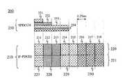
- FIG. 1shows one exemplary embodiment of the invention in the context of wireless data transmission according to the 1xEV-DV air interface standard (evolution of the cdma2000-1x standards) for third generation (3G) wireless systems. More specifically, FIG. 1 shows a simplified block diagram of a communication channel format 100 wherein a forward packet data channel (F-PDCH) 110 is used for transmitting encoder packets, according to well-known techniques, and wherein forward secondary packet data control channel (SPDCCH) 150 is used for transmitting control information associated with the data transmission in F-PDCH 110 , again according to well-known techniques.
- F-PDCHforward packet data channel
- SPDCCHforward secondary packet data control channel
- communication channel 100is divided into eight (8) time slots 111 - 118 of equal duration, e.g., 1.25 milliseconds, according to the well-known cdma2000 standard. As shown, each of times slots 111 - 118 is further sub-divided into two (2) half-slots (sub-slots) 120 and 121 . It should be noted that time slots 111 - 118 can be sub-divided into any integer number of sub-slots or resource units, e.g., four (4) quarter-slots, etc., and such sub-division is a matter of design choice.
- code division multiple accesscan be used for transmitting information within each of sub-slots 120 and 121 using well-known code multiplexing techniques.
- each of time slots 111 - 118is divided into two sub-slots 120 and 121 in the code domain, e.g., the total number of Walsh codes allocated to F-PDCH 110 can be equally or unequally divided between the two sub-slots 120 and 121 .
- time slot 111 - 118is sub-divided into multiple sub-slots (e.g., more than two) by allowing different sub-slots to use different chips within a given time slot 111 - 118 .
- userscan be allocated transmission resources within communication channel 100 on two different levels, e.g., time slots 111 - 118 in the time domain as well as sub-slots 120 - 121 , within one or more of the time slots, in the code domain.
- time slots 111 - 118 and sub-slots 120 - 121can be used to effectively provide a variable transmission feature using a fixed time period base, e.g., fixed length frames of 1.25 millisecond duration.
- userscan be allocated a prescribed number of sub-slots 120 - 121 starting in any of time slots 111 - 118 .
- FIG. 1shows transmission allocations over one-half (0.5) sub-slot (transmission 125 ), one-and-a-half (1.5) contiguous sub-slots (transmission 127 ), two-and-a-half (2.5) contiguous sub-slots (transmission 129 ), and three-and-a-half (3.5) contiguous sub-slots (transmission 130 ).
- each of transmissions 125 , 127 , 129 , and 130corresponds to separate transmissions occurring within communication channel 100 .
- these separate transmissionscould each be for separate users or could be separate transmissions for the same user.
- these examplesare meant to be illustrative only.
- time slots 111 - 118can be sub-divided into any number of sub-slots and any of time slots 111 - 118 could carry multiple transmissions within a single time slot, e.g., each separate transmission would be separately coded and simultaneously transmitted in a respective one or more sub-slots within such time slot.
- the transmissionscan start in any of time slots 111 - 118 and in either of sub-slots 120 or 121 , and the sub-slots and time slots carrying a particular transmission would be contiguous as shown by the examples of FIG. 1 .
- F-PDCHforward packet data channel
- SPDCCHforward packet data control channel
- a 5-bit pointeris used to indicate the number of 32-ary Walsh codes allocated to F-PDCH 110 .
- a predefined rulecan be used to determine the codes allocated to each sub-slot.
- the codescan be equally divided between sub-slots 120 and 121 .
- the number of codes in the first sub-slot 120can be (n+1)/2 while the number of codes in the second sub-slot 121 can be (n ⁇ 1)/2, where n is the total number of 32-ary Walsh codes allocated to F-PDCH 110 .
- the transmissions supported by the hybrid format shown in FIG. 1are not limited to just an integer number of time slots since a finer amount of data rate granularity is achieved by sub-dividing time slots into separate code-multiplexed sub-slots.
- the hybrid multiplexing schemeprovides efficient support for shorter packet transmissions since the minimum number of resources that can be allocated to a user can be smaller than one full time slot.
- the finer data rate granularityenables rate adaptation to the current channel conditions for any data block size and allows for a large number of modulation and coding schemes for the same data block size.
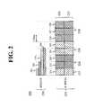
- FIG. 2shows another exemplary embodiment of the invention in which communication channel format 200 includes forward packet data channel (F-PDCH) 210 for transmitting encoder packets according to well-known techniques, and forward secondary packet data control channel (SPDCCH) 250 for transmitting control information associated with the data transmission in F-PDCH 210 , again according to well-known techniques. More specifically, FIG. 2 illustrates a signaling technique that can be used for the hybrid transmission scheme according to the principles of the invention.
- F-PDCHforward packet data channel
- SPDCCHforward secondary packet data control channel
- SPDCCH 250As is well-known, the use of SPDCCH 250 is set forth in appropriate standards for wireless communications. For example, those skilled in the art will understand that SPDCCH 250 includes fields such as EPS (3 bits), ACID (2 bits), SPID (2 bits), MAC ID (6 bits) and CRC (8 bits). According to the principles of the invention, an additional signaling field is required in SPDCCH 250 when F-PDCH 210 is carrying transmissions that are both time and code multiplexed. According to one embodiment, SPDCCH 250 is used to convey a start position for a transmission within F-PDCH 210 , e.g., a bit for identifying whether a transmission starts in sub-slot 220 or 221 in one of time slots 211 - 218 .
- the sub-slot startwith the particular SPDCCH 250 used for carrying the control information for the particular transmission in F-PDCH 210 .
- the particular SPDCCH 250used for carrying the control information for the particular transmission in F-PDCH 210 .
- the userreceives control information on the first SPDCCH 250 , this would indicate that the transmission starts in the first sub-slot in a particular time slot.
- the control informationis received on the second SPDCCH 250 , the user will know that the transmission starts in the second sub-slot.
- SPDCCH 250is also used to convey the total number of contiguous sub-slots and time slots allocated for a particular transmission, e.g., one or more bits for identifying the total number of sub-slots 220 and 221 that carry the particular transmission.
- Table 1shows one exemplary implementation of a 3-bit signaling field that can be used in SPDCCH 250 according to the principles of the invention.
- sub-slot startSSS ‘0xx’ - start in the first half slot [1 bit] ‘1xx’ - start in the second half slot sub-slot count (SSC) ‘x00’ - 1 sub-slot allocated [2 bits] ‘x01’ - 2 sub-slots allocated ‘x10’ - 3 sub-slots allocated ‘x11’ - 4 sub-slots allocated
- the first bitis a sub-slot start bit (SSS) that is set to either “0” or “1” to indicate whether the transmission in F-PDCH 210 starts in the first sub-slot 220 or the second sub-slot 221 , respectively.
- SSSsub-slot start bit
- the remaining two bitsare the sub-slot count (SSC) which, in conjunction with the length of the particular SPDCCH as will be described below, denotes the number of sub-slots 220 and 221 allocated for a transmission in F-PDCH 210 , e.g., indicating one, two, three, or four of sub-slots 220 and 221 in this example.
- SSCsub-slot count
- SPDCCH 250includes separate signaling blocks 251 - 254 for each corresponding separate transmission 227 - 230 , respectively, in F-PDCH 210 in communication channel 200 .
- the length of the particular SPDCCH 251 - 254in conjunction with the use of initial-state of registers in the well-known cyclic redundancy check (CRC) coding, can be used to provide a large set of sub-slot allocations with the 2-bit sub-slot count (SSC) field.
- CRCcyclic redundancy check
- a length of one (1) slotsuch as in SPDCCH 251
- SPDCCH 252would indicate that the transmission in F-PDCH 210 starts and ends in the same time slot, e.g., transmission 227 in time slot 211 .
- a length of two (2) time slotssuch as SPDCCH 252
- SPDCCH 252would indicate that the transmission in F-PDCH 210 can extend from one (1) to three (3) time slots.
- transmission 228spans 4 sub-slots in two (2) time slots 212 - 213 .
- the differentiation between SPDCCH 253 and 254each covering four (4) time slots, can be accomplished in one exemplary embodiment using well-known CRC techniques.
- an “all 0's” CRC statewould denote transmission in F-PDCH 210 from three (3) to five (5) time slots
- an “all 1's” CRC statewould denote transmission in F-PDCH 210 from five (5) to eight (8) time slots.
- transmission 125is a one-half (0.5) slot transmission that would have a 3-bit sub-slot field of “000” since the transmission starts in sub-slot 120 and since the transmission starts and ends within one time slot 111 .
- transmission 127is a one-and-a-half (1.5) slot transmission starting in sub-slot 121 and would therefore have a sub-slot field of “101”.
- Transmission 129is a two-and-a-half (2.5) slot transmission starting in sub-slot 120 and would therefore have a 3-bit sub-slot field of “010”, while transmission 130 is a three-and-a-half (3.5) slot transmission starting in sub-slot 121 and would therefore have a 3-bit sub-slot field of “101”.
- transmissions 127 and 130would have the same sub-slot field “101” using this signaling technique, differentiation between the two transmissions would be done based on the length of SPDCCH 150 , e.g., two (2) time slots 111 - 112 for SPDCCH 150 in the case of transmission 127 in F-PDCH 110 and four (4) time slots 115 - 118 for SPDCCH 150 in the case of transmission 130 in F-PDCH 110 .
- SPDCCH 150e.g., two (2) time slots 111 - 112 for SPDCCH 150 in the case of transmission 127 in F-PDCH 110 and four (4) time slots 115 - 118 for SPDCCH 150 in the case of transmission 130 in F-PDCH 110 .
- signaling implementationse.g., using a different number of bits and so on, would also be suitable for use in the foregoing embodiments and are therefore contemplated by the teachings herein.
- the length of SPDCCH ( 150 , 250 ), the CRC state, the sub-slot start bit (SSS), and the sub-slot count (SSC)together determine how the sub-slots are used for a subpacket transmission in accordance with the principles of the invention.
- SPDCCHthe CRC state
- SSSsub-slot start bit
- SSCsub-slot count
- each time slot( 111 - 118 , 211 - 218 ) is divided into two sub-slots ( 120 - 121 , 220 - 221 ) referred hereinafter generically as the “upper” sub-slot and “lower” sub-slot.
- the upper sub-slotwhich corresponds to the even numbered sub-slots in Table 3 below, uses W-Floor [WIK] codes, where W is the total number of 32-ary Walsh codes available for the F-PDCCH ( 110 , 210 ) at the current time, and K is a configurable (e.g., semi-static) integer that indicates the manner in which the available Walsh space is apportioned between the upper and lower sub-slots.
- the lower sub-slotwhich corresponds to the odd numbered sub-slots in Table 3 below, uses Floor [W/K] codes. As shown in the sub-slot map of Table 3, each sub-slot is numbered starting at time slot 0.
- N wis the total number of 32-ary Walsh codes used for the given combination of SPDCCH length, CRC state, SSS field, and SSC field.
- FIG. 3illustrates a method for sending acknowledgements (ACKs) and negative acknowledgements (NACKs) to account for the multiple transmissions that may occur within a given time slot. For example, when a new transmission and a retransmission or two new transmissions to the same user ends in the same time slot, a two-level ACK/NACK is needed.
- ACKsacknowledgements
- NACKsnegative acknowledgements
- a communication channelis shown in which some of time slots 311 - 318 carry new transmissions (NTX) or retransmissions (RTX) according to well known techniques.
- NTXnew transmissions
- RTXretransmission
- a new transmission (NTX) 305 for the same useroccurs in lower sub-slot of time slot 311 .
- NTXnew transmission
- a new transmission (NTX) 310 for user Awhich started in the upper sub-slot of time slot 313 , ends in the upper sub-slot of time slot 315 while a retransmission (RTX) 320 for user A occurs in the lower sub-slot of time slot 315 .
- simultaneous ACK/NACKs 350 and 351are sent from the receiver to the transmitter to account for the aforementioned transmissions.
- ACK/NACK 350includes an acknowledgement (ACK) for user A's previous retransmission, e.g., in time slot 311 , and a negative acknowledgement (NACK) for user A's transmission from time slot 311 .
- ACK/NACK 351includes an acknowledgement (ACK) for user A's previous transmission, e.g., which started in the upper sub-slot of time slot 313 and ended in the upper sub-slot of time slot 315 , and an acknowledgement (ACK) for user A's retransmission from time slot 315 .
- This two-level ACK/NACKis therefore advantageous for handling multiple transmissions that end within the same time slot.
- the receivercan use a 2-bit ACK/NACK feedback format.
Landscapes
- Engineering & Computer Science (AREA)
- Computer Networks & Wireless Communication (AREA)
- Signal Processing (AREA)
- Mobile Radio Communication Systems (AREA)
- Time-Division Multiplex Systems (AREA)
Abstract
Description
| TABLE 1 | |
| sub-slot start (SSS) | ‘0xx’ - start in the first half slot |
| [1 bit] | ‘1xx’ - start in the second half slot |
| sub-slot count (SSC) | ‘x00’ - 1 sub-slot allocated |
| [2 bits] | ‘x01’ - 2 sub-slots allocated |
| ‘x10’ - 3 sub-slots allocated | |
| ‘x11’ - 4 sub-slots allocated | |
| TABLE 2 | ||
| SPDCCH (251-254) | Effective Transmission | |
| Length | Length in F-PDCH 210 | |
| [Time Slots] | Sub-Slot Count (SSC) | [Time Slots] |
| 1 | Number of sub-slots | 0.5, 1 |
| allocated in the | ||
| 1sttime slot. | ||
| 2 | Number of sub-slots | 1, 1.5, 2.0, 2.5, 3.0 |
| allocated in the 2nd | ||
| and 3rdtime slots. | ||
| 4 with all ‘0’s CRC | Number of sub-slots | 3.0, 3.5, 4.0, 4.5, 5.0 |
| state | allocated in the 4thand | |
| 5thtime slots. | ||
| 4 with all ‘1’ CRC | Number of sub-slots | 5, 5.5, 6, 6.5, 7, 7.5, 8 |
| state | allocated in the 6th | |
| slot or number of full | ||
| slots from the 7thand 8th | ||
| time slots. | ||
| TABLE 3 | ||||||||
| Sub-slot | 0 | 2 | 4 | 6 | 8 | 10 | 12 | 14 |
| number | 1 | 3 | 5 | 7 | 9 | 11 | 13 | 15 |
| Time Slot | Slot 0 | Slot 1 | Slot 2 | Slot 3 | Slot 5 | Slot 6 | Slot 7 | |
| number | ||||||||
| TABLE 4 | |||||
| Slots used for | |||||
| sub-packet | |||||
| transmission - | |||||
| SPDCCH | CRC | SSS + | partially or fully | Sub-slot | |
| length | state | SSC | (see Table 3) | usage map | Nw |
| 1 | 0 | 000 | 0 | 0 | WU |
| 1 | 0 | 001 | 0 | 0 to 1 | W |
| 1 | 0 | 010 | N/A | N/A | N/A |
| 1 | 0 | 011 | N/A | N/A | N/A |
| 1 | 0 | 100 | 0 | 1 | WL |
| 1 | 0 | 101 | N/A | N/A | N/A |
| 1 | 0 | 110 | N/A | N/A | N/A |
| 1 | 0 | 111 | N/A | N/A | N/A |
| 2 | 0 | 000 | 0 to 1 | 0 to 2 | W + WU |
| 2 | 0 | 001 | 0 to 1 | 0 to 3 | 2W |
| 2 | 0 | 010 | 0 to 2 | 0 to 4 | 2W + WU |
| 2 | 0 | 011 | 0 to 2 | 0 to 5 | 3W |
| 2 | 0 | 100 | 0 to 1 | 1 to 2 | W |
| 2 | 0 | 101 | 0 to 1 | 1 to 3 | W + WL |
| 2 | 0 | 110 | 0 to 2 | 1 to 4 | 2W |
| 2 | 0 | 111 | 0 to 2 | 1 to 5 | 2W + WL |
| 4 | 0 | 000 | 0 to 3 | 0 to 6 | 3W + WU |
| 4 | 0 | 001 | 0 to 3 | 0 to 7 | 4W |
| 4 | 0 | 010 | 0 to 4 | 0 to 8 | 4W + WU |
| 4 | 0 | 011 | 0 to 4 | 0 to 9 | 5W |
| 4 | 0 | 100 | 0 to 3 | 1 to 6 | 3W |
| 4 | 0 | 101 | 0 to 3 | 1 to 7 | 3W + WL |
| 4 | 0 | 110 | 0 to 4 | 1 to 8 | 4W |
| 4 | 0 | 111 | 0 to 4 | 1 to 9 | 4W + WL |
| 4 | 1 | 000 | 0 to 5 | 0 to 10 | 5W + WU |
| 4 | 1 | 001 | 0 to 5 | 0 to 11 | 6W |
| 4 | 1 | 010 | 0 to 6 | 0 to 13 | 7W |
| 4 | 1 | 011 | 0 to 7 | 0 to 15 | 8W |
| 4 | 1 | 100 | 0 to 5 | 1 to 10 | 5W |
| 4 | 1 | 101 | 0 to 5 | 1 to 11 | 5W + WL |
| 4 | 1 | 110 | 0 to 6 | 1 to 13 | 6W + WL |
| 4 | 1 | 111 | 0 to 7 | 1 to 15 | 7W + WL |
Claims (13)
Priority Applications (3)
| Application Number | Priority Date | Filing Date | Title |
|---|---|---|---|
| US09/982,317US8289933B2 (en) | 2001-10-18 | 2001-10-18 | Hybrid transmission method for wireless communications |
| EP02253061AEP1306985A1 (en) | 2001-10-18 | 2002-04-30 | A hybrid transmission method for wireless communications |
| JP2002298527AJP2003188852A (en) | 2001-10-18 | 2002-10-11 | Hybrid transmission method for wireless communications |
Applications Claiming Priority (1)
| Application Number | Priority Date | Filing Date | Title |
|---|---|---|---|
| US09/982,317US8289933B2 (en) | 2001-10-18 | 2001-10-18 | Hybrid transmission method for wireless communications |
Publications (2)
| Publication Number | Publication Date |
|---|---|
| US20030096613A1 US20030096613A1 (en) | 2003-05-22 |
| US8289933B2true US8289933B2 (en) | 2012-10-16 |
Family
ID=25529032
Family Applications (1)
| Application Number | Title | Priority Date | Filing Date |
|---|---|---|---|
| US09/982,317Active2027-07-02US8289933B2 (en) | 2001-10-18 | 2001-10-18 | Hybrid transmission method for wireless communications |
Country Status (3)
| Country | Link |
|---|---|
| US (1) | US8289933B2 (en) |
| EP (1) | EP1306985A1 (en) |
| JP (1) | JP2003188852A (en) |
Cited By (1)
| Publication number | Priority date | Publication date | Assignee | Title |
|---|---|---|---|---|
| US11190862B1 (en) | 2020-11-16 | 2021-11-30 | Rockwell Collins, Inc. | Enhanced high frequency avalanche relay protocol |
Families Citing this family (17)
| Publication number | Priority date | Publication date | Assignee | Title |
|---|---|---|---|---|
| CN100590991C (en)* | 2002-01-30 | 2010-02-17 | Lg电子株式会社 | Method for scrambling packet data using variable slot length and apparatus therefor |
| US7826471B2 (en)* | 2003-03-11 | 2010-11-02 | Nortel Networks Limited | Multi-beam cellular communication system |
| EP1623540A1 (en)* | 2003-05-13 | 2006-02-08 | Nokia Corporation | A traffic management method that divides time slots into sub-blocks for real time and non-real time traffic |
| FI20030712A0 (en) | 2003-05-13 | 2003-05-13 | Nokia Corp | Traffic management method and network element |
| US7539507B2 (en)* | 2003-11-21 | 2009-05-26 | Qualcomm Incorporated | Peer-to-peer communications |
| US8804609B2 (en)* | 2004-11-02 | 2014-08-12 | Apple Inc. | Systems and methods for use with orthogonal frequency division multiplexing |
| US8638771B2 (en)* | 2005-08-12 | 2014-01-28 | Qualcomm Incorporated | Transmission structure supporting multi-user scheduling and MIMO transmission |
| KR100946901B1 (en) | 2006-02-07 | 2010-03-09 | 삼성전자주식회사 | Resource allocation method and system in communication system |
| KR20070095728A (en)* | 2006-03-22 | 2007-10-01 | 삼성전자주식회사 | Packet data transmission and reception apparatus and method in mobile communication system |
| EP1855424B1 (en)* | 2006-05-12 | 2013-07-10 | Panasonic Corporation | Reservation of radio resources for users in a mobile communications system |
| US8554236B2 (en)* | 2007-06-18 | 2013-10-08 | Intel Mobile Communications GmbH | Method for transmitting data and transmitter |
| US7855997B2 (en)* | 2007-08-01 | 2010-12-21 | Harris Corporation | Long range scheduling for directional antenna manet networks |
| US20090061885A1 (en)* | 2007-08-27 | 2009-03-05 | Motorola, Inc. | System and method for contagious virtual carrier sense |
| US8532066B2 (en)* | 2007-10-18 | 2013-09-10 | Qualcomm Incorporated | Transmission structure supporting multi-user scheduling and MIMO transmission |
| US20120021755A1 (en)* | 2010-07-23 | 2012-01-26 | Tom Chin | Resource allocation in a multiple usim mobile station |
| CN108632886B (en) | 2017-03-21 | 2020-11-06 | 华为技术有限公司 | A business processing method and device |
| CN111511022B (en)* | 2019-01-31 | 2024-08-02 | 中兴通讯股份有限公司 | Method, device and system for transmitting customer service |
Citations (22)
| Publication number | Priority date | Publication date | Assignee | Title |
|---|---|---|---|---|
| US4763322A (en)* | 1985-07-31 | 1988-08-09 | U.S. Philips Corp. | Digital radio transmission system with variable duration of the time slots in the time-division multiplex frame |
| EP0538546A2 (en) | 1986-03-25 | 1993-04-28 | Motorola Inc. | Method and apparatus for controlling a TDM communication device |
| EP0633671A2 (en) | 1993-07-08 | 1995-01-11 | Nokia Mobile Phones Ltd. | A multiple access radio system |
| EP0680168A2 (en) | 1994-04-28 | 1995-11-02 | AT&T Corp. | System and method for optimizing spectral efficiency using time-frequency-code slicing |
| EP0841763A1 (en) | 1996-10-25 | 1998-05-13 | Nokia Mobile Phones Ltd. | Method for radio resource control |
| US5790549A (en)* | 1996-02-29 | 1998-08-04 | Ericsson Inc. | Subtractive multicarrier CDMA access methods and systems |
| JPH11243380A (en) | 1998-02-26 | 1999-09-07 | Atr Kankyo Tekio Tsushin Kenkyusho:Kk | Channel assignment device for wireless networks |
| EP0980153A2 (en) | 1998-08-12 | 2000-02-16 | Lucent Technologies Inc. | A method for formatting and conveying information in a wireless telecommunication system |
| US6031827A (en) | 1996-10-25 | 2000-02-29 | Nokia Mobile Phones Limited | Method for radio resource control |
| EP1059740A1 (en) | 1999-06-09 | 2000-12-13 | Lucent Technologies Inc. | Time-slot partitioning in a TDMA system |
| WO2001022742A2 (en) | 1999-09-23 | 2001-03-29 | Winrich Hoseit | Telephone communication system based on dual-tone multi-frequency signaling |
| WO2001033742A1 (en) | 1999-11-03 | 2001-05-10 | Ericsson Inc | Methods and apparatus for allocating resources in hybrid tdma communications systems |
| US20030039204A1 (en)* | 2001-06-07 | 2003-02-27 | Tiedemann Edward G. | Method and apparatus for walsh space assignment in a communication system |
| US6535503B1 (en)* | 1996-10-15 | 2003-03-18 | Nokia Telecommunications | Channel allocation method and radio system using a combination of TDMA and CDMA |
| US6665309B2 (en)* | 2001-09-20 | 2003-12-16 | Nokia Corporation | Apparatus, and associated method, for generating assignment information used pursuant to channel allocation in a radio communication system |
| US6721294B1 (en)* | 1998-03-25 | 2004-04-13 | Siemens Aktiengesellschaft | Method and device for allocating channels in a CDMA radiocommunications system |
| US6791994B1 (en)* | 2000-04-19 | 2004-09-14 | Rockwell Collins, Inc. | Method and apparatus for assigning receive slots in a dynamic assignment environment |
| US6804220B2 (en)* | 2001-05-07 | 2004-10-12 | Qualcomm Incorporated | Method and apparatus for generating control information for packet data |
| US6952454B1 (en)* | 2000-03-22 | 2005-10-04 | Qualcomm, Incorporated | Multiplexing of real time services and non-real time services for OFDM systems |
| US6952410B2 (en)* | 2001-02-26 | 2005-10-04 | Lucent Technologies Inc. | Semi-static code space division for multiple shared packet data channels in high bandwidth mixed service CDMA systems |
| US6996082B2 (en)* | 2001-05-14 | 2006-02-07 | Interdigital Technology Corporation | Method and apparatus for minimizing the amount of data necessary to signal code and timeslot assignments |
| US7167461B2 (en)* | 2001-10-15 | 2007-01-23 | Qualcomm Incorporated | Method and apparatus for processing shared subpackets in a communication system |
- 2001
- 2001-10-18USUS09/982,317patent/US8289933B2/enactiveActive
- 2002
- 2002-04-30EPEP02253061Apatent/EP1306985A1/ennot_activeCeased
- 2002-10-11JPJP2002298527Apatent/JP2003188852A/enactivePending
Patent Citations (26)
| Publication number | Priority date | Publication date | Assignee | Title |
|---|---|---|---|---|
| US4763322A (en)* | 1985-07-31 | 1988-08-09 | U.S. Philips Corp. | Digital radio transmission system with variable duration of the time slots in the time-division multiplex frame |
| EP0538546A2 (en) | 1986-03-25 | 1993-04-28 | Motorola Inc. | Method and apparatus for controlling a TDM communication device |
| EP0633671A2 (en) | 1993-07-08 | 1995-01-11 | Nokia Mobile Phones Ltd. | A multiple access radio system |
| US5577024A (en)* | 1993-07-08 | 1996-11-19 | Nokia Mobile Phones Ltd. | Multiple access radio system |
| US6018528A (en) | 1994-04-28 | 2000-01-25 | At&T Corp | System and method for optimizing spectral efficiency using time-frequency-code slicing |
| EP0680168A2 (en) | 1994-04-28 | 1995-11-02 | AT&T Corp. | System and method for optimizing spectral efficiency using time-frequency-code slicing |
| US6064662A (en)* | 1994-04-28 | 2000-05-16 | At&T Corp | System and method for optimizing spectral efficiency using time-frequency-code slicing |
| US5790549A (en)* | 1996-02-29 | 1998-08-04 | Ericsson Inc. | Subtractive multicarrier CDMA access methods and systems |
| US6535503B1 (en)* | 1996-10-15 | 2003-03-18 | Nokia Telecommunications | Channel allocation method and radio system using a combination of TDMA and CDMA |
| US6031827A (en) | 1996-10-25 | 2000-02-29 | Nokia Mobile Phones Limited | Method for radio resource control |
| EP0841763A1 (en) | 1996-10-25 | 1998-05-13 | Nokia Mobile Phones Ltd. | Method for radio resource control |
| JPH11243380A (en) | 1998-02-26 | 1999-09-07 | Atr Kankyo Tekio Tsushin Kenkyusho:Kk | Channel assignment device for wireless networks |
| US6721294B1 (en)* | 1998-03-25 | 2004-04-13 | Siemens Aktiengesellschaft | Method and device for allocating channels in a CDMA radiocommunications system |
| EP0980153A2 (en) | 1998-08-12 | 2000-02-16 | Lucent Technologies Inc. | A method for formatting and conveying information in a wireless telecommunication system |
| EP1059740A1 (en) | 1999-06-09 | 2000-12-13 | Lucent Technologies Inc. | Time-slot partitioning in a TDMA system |
| WO2001022742A2 (en) | 1999-09-23 | 2001-03-29 | Winrich Hoseit | Telephone communication system based on dual-tone multi-frequency signaling |
| WO2001033742A1 (en) | 1999-11-03 | 2001-05-10 | Ericsson Inc | Methods and apparatus for allocating resources in hybrid tdma communications systems |
| US6631124B1 (en)* | 1999-11-03 | 2003-10-07 | Ericsson Inc. | Methods and apparatus for allocating resources in hybrid TDMA communication systems |
| US6952454B1 (en)* | 2000-03-22 | 2005-10-04 | Qualcomm, Incorporated | Multiplexing of real time services and non-real time services for OFDM systems |
| US6791994B1 (en)* | 2000-04-19 | 2004-09-14 | Rockwell Collins, Inc. | Method and apparatus for assigning receive slots in a dynamic assignment environment |
| US6952410B2 (en)* | 2001-02-26 | 2005-10-04 | Lucent Technologies Inc. | Semi-static code space division for multiple shared packet data channels in high bandwidth mixed service CDMA systems |
| US6804220B2 (en)* | 2001-05-07 | 2004-10-12 | Qualcomm Incorporated | Method and apparatus for generating control information for packet data |
| US6996082B2 (en)* | 2001-05-14 | 2006-02-07 | Interdigital Technology Corporation | Method and apparatus for minimizing the amount of data necessary to signal code and timeslot assignments |
| US20030039204A1 (en)* | 2001-06-07 | 2003-02-27 | Tiedemann Edward G. | Method and apparatus for walsh space assignment in a communication system |
| US6665309B2 (en)* | 2001-09-20 | 2003-12-16 | Nokia Corporation | Apparatus, and associated method, for generating assignment information used pursuant to channel allocation in a radio communication system |
| US7167461B2 (en)* | 2001-10-15 | 2007-01-23 | Qualcomm Incorporated | Method and apparatus for processing shared subpackets in a communication system |
Non-Patent Citations (2)
| Title |
|---|
| Oguz Sunay, "C502000-0918-014 1xEV-DV Forward Channel Structure", Announcement Lucent, Sep. 20, 2000, pp. 1-29. |
| Ojanpera et al., "Comparison of Multiple Access Schemes for UMTS", Vehicular Technology Conference, 1997, IEEE 47thPhoenix, AZ, USA May 4-7, 1997, pp. 490-494. |
Cited By (1)
| Publication number | Priority date | Publication date | Assignee | Title |
|---|---|---|---|---|
| US11190862B1 (en) | 2020-11-16 | 2021-11-30 | Rockwell Collins, Inc. | Enhanced high frequency avalanche relay protocol |
Also Published As
| Publication number | Publication date |
|---|---|
| JP2003188852A (en) | 2003-07-04 |
| EP1306985A1 (en) | 2003-05-02 |
| US20030096613A1 (en) | 2003-05-22 |
Similar Documents
| Publication | Publication Date | Title |
|---|---|---|
| US8289933B2 (en) | Hybrid transmission method for wireless communications | |
| US10701683B1 (en) | Communication system | |
| US6970438B2 (en) | Method and device for downlink packet switching | |
| US7508804B2 (en) | Shared signaling for multiple user equipment | |
| US7304971B2 (en) | Flexible transmission method for wireless communications | |
| US8693383B2 (en) | Method and apparatus for high rate data transmission in wireless communication | |
| RU2343635C1 (en) | Method and device for transmitting and receiving downlink control information in mobile communications system, supporting up-link data packet transfer service | |
| CN1331364C (en) | Method for transmitting-receiving information about orthogonal variable spread spectrum factor code | |
| US9106379B2 (en) | Method for transmitting control signal using efficient multiplexing | |
| JP2009118535A (en) | Physical channel configuration signaling procedure | |
| US8369361B2 (en) | Early termination of low data rate traffic in a wireless network | |
| US20050271027A1 (en) | Apparatus and method for multiplexing packets for broadcast services in a mobile communication system based on orthogonal frequency division multiplexing | |
| US20050195849A1 (en) | Early termination of low data rate traffic in a wireless network | |
| CN102088344B (en) | Method and equipment for transmitting ACK/NACK information | |
| US7664140B2 (en) | Early termination of low data rate traffic in a wireless network | |
| II | Das et a].(45) Date of Patent: Oct. 16, 2012 | |
| KR100800814B1 (en) | Packet data control channel information transmission device in mobile communication system | |
| WO2002078236A2 (en) | A communication system |
Legal Events
| Date | Code | Title | Description |
|---|---|---|---|
| AS | Assignment | Owner name:LUCENT TECHNOLOGIES, INC., NEW JERSEY Free format text:ASSIGNMENT OF ASSIGNORS INTEREST;ASSIGNORS:DAS, ARNAB;KHAN, FAROOQ ULLAH;REEL/FRAME:012284/0497 Effective date:20011017 | |
| FEPP | Fee payment procedure | Free format text:PAYOR NUMBER ASSIGNED (ORIGINAL EVENT CODE: ASPN); ENTITY STATUS OF PATENT OWNER: LARGE ENTITY | |
| AS | Assignment | Owner name:ALCATEL-LUCENT USA INC., NEW JERSEY Free format text:MERGER;ASSIGNOR:LUCENT TECHNOLOGIES INC.;REEL/FRAME:028748/0040 Effective date:20081101 | |
| AS | Assignment | Owner name:ALCATEL LUCENT, FRANCE Free format text:ASSIGNMENT OF ASSIGNORS INTEREST;ASSIGNOR:ALCATEL-LUCENT USA INC.;REEL/FRAME:028787/0981 Effective date:20120814 | |
| STCF | Information on status: patent grant | Free format text:PATENTED CASE | |
| AS | Assignment | Owner name:CREDIT SUISSE AG, NEW YORK Free format text:SECURITY AGREEMENT;ASSIGNOR:LUCENT, ALCATEL;REEL/FRAME:029821/0001 Effective date:20130130 Owner name:CREDIT SUISSE AG, NEW YORK Free format text:SECURITY AGREEMENT;ASSIGNOR:ALCATEL LUCENT;REEL/FRAME:029821/0001 Effective date:20130130 | |
| AS | Assignment | Owner name:ALCATEL LUCENT, FRANCE Free format text:RELEASE BY SECURED PARTY;ASSIGNOR:CREDIT SUISSE AG;REEL/FRAME:033868/0001 Effective date:20140819 | |
| FPAY | Fee payment | Year of fee payment:4 | |
| AS | Assignment | Owner name:NOKIA TECHNOLOGIES OY, FINLAND Free format text:ASSIGNMENT OF ASSIGNORS INTEREST;ASSIGNOR:ALCATEL LUCENT;REEL/FRAME:047271/0246 Effective date:20180702 | |
| MAFP | Maintenance fee payment | Free format text:PAYMENT OF MAINTENANCE FEE, 8TH YEAR, LARGE ENTITY (ORIGINAL EVENT CODE: M1552); ENTITY STATUS OF PATENT OWNER: LARGE ENTITY Year of fee payment:8 | |
| MAFP | Maintenance fee payment | Free format text:PAYMENT OF MAINTENANCE FEE, 12TH YEAR, LARGE ENTITY (ORIGINAL EVENT CODE: M1553); ENTITY STATUS OF PATENT OWNER: LARGE ENTITY Year of fee payment:12 |