US8289821B1 - Method and system for pulsing EAMR disk drives - Google Patents
Method and system for pulsing EAMR disk drivesDownload PDFInfo
- Publication number
- US8289821B1 US8289821B1US12/973,957US97395710AUS8289821B1US 8289821 B1US8289821 B1US 8289821B1US 97395710 AUS97395710 AUS 97395710AUS 8289821 B1US8289821 B1US 8289821B1
- Authority
- US
- United States
- Prior art keywords
- laser
- eamr
- write
- signal
- clock recovery
- Prior art date
- Legal status (The legal status is an assumption and is not a legal conclusion. Google has not performed a legal analysis and makes no representation as to the accuracy of the status listed.)
- Active, expires
Links
- 238000000034methodMethods0.000titleclaimsabstractdescription24
- 238000011084recoveryMethods0.000claimsabstractdescription87
- 230000001360synchronised effectEffects0.000claimsdescription8
- 230000007704transitionEffects0.000claimsdescription6
- 230000001934delayEffects0.000description6
- 238000013021overheatingMethods0.000description6
- 238000010586diagramMethods0.000description5
- 230000003287optical effectEffects0.000description3
- 239000000725suspensionSubstances0.000description1
Images


Classifications
- G—PHYSICS
- G11—INFORMATION STORAGE
- G11B—INFORMATION STORAGE BASED ON RELATIVE MOVEMENT BETWEEN RECORD CARRIER AND TRANSDUCER
- G11B5/00—Recording by magnetisation or demagnetisation of a record carrier; Reproducing by magnetic means; Record carriers therefor
- G11B5/02—Recording, reproducing, or erasing methods; Read, write or erase circuits therefor
- G—PHYSICS
- G11—INFORMATION STORAGE
- G11B—INFORMATION STORAGE BASED ON RELATIVE MOVEMENT BETWEEN RECORD CARRIER AND TRANSDUCER
- G11B20/00—Signal processing not specific to the method of recording or reproducing; Circuits therefor
- G11B20/10—Digital recording or reproducing
- G11B20/10009—Improvement or modification of read or write signals
- G11B20/10222—Improvement or modification of read or write signals clock-related aspects, e.g. phase or frequency adjustment or bit synchronisation
- G—PHYSICS
- G11—INFORMATION STORAGE
- G11B—INFORMATION STORAGE BASED ON RELATIVE MOVEMENT BETWEEN RECORD CARRIER AND TRANSDUCER
- G11B5/00—Recording by magnetisation or demagnetisation of a record carrier; Reproducing by magnetic means; Record carriers therefor
- G11B2005/0002—Special dispositions or recording techniques
- G11B2005/0005—Arrangements, methods or circuits
- G11B2005/0021—Thermally assisted recording using an auxiliary energy source for heating the recording layer locally to assist the magnetization reversal
- G—PHYSICS
- G11—INFORMATION STORAGE
- G11B—INFORMATION STORAGE BASED ON RELATIVE MOVEMENT BETWEEN RECORD CARRIER AND TRANSDUCER
- G11B5/00—Recording by magnetisation or demagnetisation of a record carrier; Reproducing by magnetic means; Record carriers therefor
- G11B5/48—Disposition or mounting of heads or head supports relative to record carriers ; arrangements of heads, e.g. for scanning the record carrier to increase the relative speed
- G11B5/58—Disposition or mounting of heads or head supports relative to record carriers ; arrangements of heads, e.g. for scanning the record carrier to increase the relative speed with provision for moving the head for the purpose of maintaining alignment of the head relative to the record carrier during transducing operation, e.g. to compensate for surface irregularities of the latter or for track following
- G11B5/60—Fluid-dynamic spacing of heads from record-carriers
- G11B5/6005—Specially adapted for spacing from a rotating disc using a fluid cushion
- G11B5/6011—Control of flying height
- G11B5/607—Control of flying height using thermal means
- G—PHYSICS
- G11—INFORMATION STORAGE
- G11B—INFORMATION STORAGE BASED ON RELATIVE MOVEMENT BETWEEN RECORD CARRIER AND TRANSDUCER
- G11B5/00—Recording by magnetisation or demagnetisation of a record carrier; Reproducing by magnetic means; Record carriers therefor
- G11B5/48—Disposition or mounting of heads or head supports relative to record carriers ; arrangements of heads, e.g. for scanning the record carrier to increase the relative speed
- G11B5/58—Disposition or mounting of heads or head supports relative to record carriers ; arrangements of heads, e.g. for scanning the record carrier to increase the relative speed with provision for moving the head for the purpose of maintaining alignment of the head relative to the record carrier during transducing operation, e.g. to compensate for surface irregularities of the latter or for track following
- G11B5/60—Fluid-dynamic spacing of heads from record-carriers
- G11B5/6005—Specially adapted for spacing from a rotating disc using a fluid cushion
- G11B5/6011—Control of flying height
- G11B5/6076—Detecting head-disk contact
Definitions
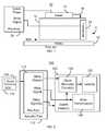
- FIG. 1depicts a side view of portion of a conventional energy assisted magnetic recording (EAMR) disk drive 10 .
- the EAMR disk drive 10includes an EAMR head 11 including a slider 12 and a transducer 20 .
- THE EAMR disk drive 10also includes a laser/light source 14 , optics 16 for directing light from the laser 14 , media 18 , a transducer 20 , and preamplifier and associated circuitry 30 .
- the laser 14is typically a laser diode. Although shown as mounted on the slider 11 , the laser 14 may be coupled with the slider 11 in another fashion. For example, the laser 11 might be mounted on a suspension (not shown in FIG. 1 ) to which the slider 11 is also attached.
- the media 18may include multiple layers, which are not shown in FIG. 1 for simplicity.
- the EAMR head 11includes an EAMR transducer 20 .
- the EAMR head 11may also include a read transducer (not shown in FIG. 1 ).
- the read transducermay be included if the EAMR head 11 is a merged head.
- the EAMR transducer 20includes optical components (not shown in FIG. 1 ) as well as magnetic components (not shown in FIG. 1 ).
- the pre-amplifier 30is typically located remote from the slider 12 .
- the pre-amplifiermay reside on a flexible printed circuit board (actuator flex).
- the actuator flexprovides mechanical and electrical connection between a system on a chip (SOC) including other electronics and the slider 12 , which is typically mounted on the actuator flex.
- SOCsystem on a chip
- the conventional pre-amplifier 30provides DC power for the conventional laser diode 14 and power for the transducer 20 .
- the pre-amplifier 30may be connected by two lines for a fly height sensor that helps determine the distance between the ABS and the media, one to two lines for a fly height control heater and ground, two lines for read data, and two lines for the write data.
- the pre-amplifier 30provides a constant power signal to the laser 14 during writing.
- the laser 14remains on throughout the write operations.
- the laser 14provides a constant source of energy, which is used to heat small regions of the media 18 .
- the pre-amplifier 30also provides write signals to the transducer 20 .
- the write signalsselectively energize one or more coils (not shown in FIG. 1 ). These coils energize a write pole (not shown in FIG. 1 ).
- the transducer 20then magnetically writes to the media 18 in the heated region.
- the conventional EAMR disk drive 10functions, it is desirable to reduce power consumption of the EAMR disk drive 10 . Electrical connectivity is still desired to be made to the EAMR transducer 20 . Further, smaller components are desired to be used to support higher density magnetic recording.
- the disk driveincludes a magnetic recording media, a pre-amplifier, an EAMR head, and at least one clock recovery circuit.
- the pre-amplifierprovides a write current signal and a write gate signal for providing power to the EAMR head.
- the EAMR headincludes at least one write transducer and at least one laser.
- the write transducer(s)are coupled with the pre-amplifier and include at least one writer coil.
- the write current signal from the pre-amplifierdrives the writer coil(s).
- the clock recovery circuit(s)are coupled with the laser(s).
- the clock recovery circuit(s)receive the write current signal and the write gate signal and output laser control signal(s) that energize the laser(s) such that the laser(s) are energized synchronously with the writer coil(s).
- FIG. 1is a diagram depicting a portion of a conventional energy assisted magnetic recording disk drive.
- FIGS. 2-3are diagrams depicting an exemplary embodiment of an EAMR disk drive.
- FIG. 4is a depicting an exemplary embodiment of an EAMR disk drive.
- FIG. 5is a depicting another exemplary embodiment of an EAMR disk drive.
- FIGS. 6-7are diagrams depicting an exemplary embodiment of an EAMR disk drive.
- FIG. 8is a depicting an exemplary embodiment of an EAMR disk drive.
- FIG. 9is a depicting another exemplary embodiment of an EAMR disk drive.
- FIG. 10is a flow chart depicting another exemplary embodiment of a method for using the EAMR head.
- FIG. 11is a graph depicting an exemplary embodiment of data signals for the EAMR transducer and laser.
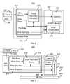
- FIGS. 2-3depict one embodiment of an EAMR disk drive 100 .
- FIG. 2is a diagram depicting a portion of an EAMR disk drive 100 .
- FIG. 2is not to scale.
- the disk drive 100is depicted in the context of particular components other and/or different components may be used. Further, the arrangement of components may vary in different embodiments.
- the EAMR disk drive 100includes an actuator flex 110 having a preamplifier 112 , EAMR head(s) 120 , an SOC 142 having a clock 144 , and media 150 .
- the laser 122is a laser diode. Although shown as mounted on the slider 121 , the laser 122 may be coupled with the slider 121 in another fashion.
- the media 150may include multiple layers, which are not shown in FIG. 2 for simplicity.
- the EAMR head(s) 120includes a slider 121 , a laser/light source 122 , clock recovery circuit(s) 130 , and an EAMR transducer 140 .
- the EAMR head 120may also include a read transducer (not shown in FIG. 2 ).
- the read transducermay be included if the EAMR head 120 is a merged head.
- the EAMR transducer 140includes optical components (not shown in FIG. 2 ) as well as magnetic components (not shown in FIG. 2 ).
- the pre-amplifier 112resides on the actuator flex 110 and has as an input the clock signal from the clock 144 . Although shown as residing in the SOC 142 , the clock 144 may be at another location.
- the pre-amplifier 112provides multiple signals to the EAMR head 120 . In the embodiment shown, the pre-amplifier 112 provides a write signal.
- the write signalis provided to writer coil(s) (not shown in FIGS. 2-3 ) for energizing the pole (not shown) of the EAMR transducer 140 to write to the media 150 .
- the write gate signalmay also include power for the components on the EAMR head 120 .
- the write signalis also provided to the clock recovery circuit(s) 130 .
- the pre-amplifier 140also provides a write gate signal to the clock recovery circuit(s) 130 .
- the write gate signal from the preamplifier 112may also drive associated electronics for the laser 122 .
- the pre-amplifier 112may also provide other signals to the EAMR head(s) 120 .
- signalsmay be provided to a fly height sensor and a heater for fly height control. In other embodiments, fewer, other and/or additional signals might be provided by the pre-amplifier to the EAMR head(s) 120 .
- the clock recovery circuit(s) 130are used to drive the laser 122 . Although only one clock recovery circuit 130 and laser 122 are shown, multiple may be included in the EAMR head(s) 120 . In the embodiment shown, the clock recovery circuit(s) 130 reside in proximity to the laser 122 . In some embodiments, the clock recovery circuit 130 may be part of the laser diode 122 . In other embodiments, the clock recovery circuits(s) 130 may reside on another portion of the slider 121 . The clock recovery circuit(s) 130 utilize the write signal(s) and the write gate signal from the pre-amplifier to drive the laser 122 . In particular, the clock recovery circuit(s) 130 synchronizes the laser with the writing of the EAMR transducer 140 .
- the clock recovery circuit 130outputs at least one laser control signal that energizes the laser 122 such that the laser is energized synchronously with the writer coil.
- the laser control signaldrives the laser 122 such that the laser 122 is synchronized with the write coil(s) that energize the pole of the EAMR transducer 120 .
- the laser 122can be driven synchronously with the write coils of the EAMR transducer 140 .
- the clock recovery circuit(s) 130account for, among other issues, differences in the delay of the clock signal from the clock 144 to the EAMR transducer 130 and the clock signal from the clock 144 to the laser 122 .
- the laser 122may be pulsed in time with the write signal instead of driven continuously. As a result, a higher peak energy may be used with lower average power, without overheating the laser 122 . Consequently, performance of the EAMR disk drive 100 may be enhanced.
- FIG. 4depicts In an EAMR disk drive 100 ′.
- the EAMR disk drive 100 ′is analogous to the EAMR disk drive 100 .
- the EAMR disk drive 100 ′thus includes components having an analogous structure and function to components in the EAMR disk drive 100 .
- the EAMR disk drive 100 ′thus includes a pre-amplifier 112 ′, EAMR head(s) 120 ′, laser(s) 122 ′, clock recovery circuit(s) 130 ′, and EAMR transducer 140 ′ that are analogous to pre-amplifier 112 , EAMR head(s) 120 , laser(s) 122 , clock recovery circuit(s) 130 , and EAMR transducer 140 , respectively.
- Selected portions of the EAMR transducer 140 ′are also shown.
- coil(s) 142 , read sensor(s) 144 , fly height control heater(s) 146 , and fly height sensor(s) 148are shown. Additional components, such as poles, shields, and/or other structures are not shown for clarity.
- SOC 142 , clock 144 , and actuator flex 110 shown in FIG. 3have been omitted in FIG. 4 .
- the clock recovery circuit(s) 130 ′include components 132 and 134 .
- the clock recovery circuit(s) 130 ′include a phase detector 132 and phase resettable oscillator 134 .
- the phase detector 132 and phase resettable oscillator 134form a phase locked loop.
- the phase detector 132includes inputs for the write gate signal, the laser control signal(s) generated by the clock recovery circuit 100 ′, and the write gate signal(s).
- the phase detector 132outputs a phase signal to the phase resettable oscillator 134 .
- the phase resettable oscillator 134receives an input from the write gate signal and the phase signal from the phase detector 132 .
- the phase resettable oscillator 134outputs the laser control signal to the laser 122 ′.
- the laser control signalis also fed back to the phase detector 132 .
- a phase locked loopis formed in the clock recovery circuit 130 ′.
- the proposed number of lines between the pre-amplifier 112 ′ and the EAMR head(s) 120 ′may be used.
- the write gate signal and any power providedmay be carried on one line.
- the write signaluses two lines to carry write data.
- the read datamay also be carried on two lines.
- the heater signal and ground returns for the fly height control heater(s) 146may be carried on one or two lines.
- the fly height/touchdown sensor datais provided from the fly height sensor 148 on two lines.
- phase lock loop formed by the phase detector 132 and phase resettable oscillator 134synchronizes the laser 122 ′ with the write signal to the coil(s) 142 .
- the laser 122 ′may be pulsed in time with the coil(s) 142 instead of driven continuously.
- higher peak energymay be used, without overheating the laser 122 ′. Consequently, performance of the EAMR disk drive 100 ′ may be enhanced.
- FIG. 5depicts In an EAMR disk drive 100 ′′.
- the EAMR disk drive 100 ′′is analogous to the EAMR disk drives 100 and 100 ′.
- the EAMR disk drive 100 ′′thus includes components having an analogous structure and function to components in the EAMR disk drive 100 .
- the EAMR disk drive 100 ′′thus includes a pre-amplifier 112 ′′, EAMR head(s) 120 ′′, laser(s) 122 ′′, clock recovery circuit(s) 130 ′′, and EAMR transducer 140 ′′ that are analogous to pre-amplifier 112 , EAMR head(s) 120 , laser(s) 122 , clock recovery circuit(s) 130 , and EAMR transducer 140 , respectively.
- Selected portions of the EAMR transducer 140 ′′are also shown.
- coil(s) 142 ′, read sensor(s) 144 ′, fly height control heater(s) 146 ′, and fly height sensor(s) 148 ′are shown. Additional components, such as poles, shields, and/or other structures are not shown for clarity.
- SOC 142 , clock 144 , and actuator flex 110 shown in FIG. 3have been omitted in FIG. 5 .
- the clock recovery circuit(s) 130 ′′include phase resettable oscillator 134 ′.
- the phase detector 132 shown in FIG. 4has been omitted from the embodiment shown in FIG. 5 .
- the phase resettable oscillator 134 ′may be used alone in embodiments in which some downstream timing errors are acceptable. In some embodiments, a buffer or other means for introducing a delay may be used in the clock recovery circuit 130 ′′ or elsewhere.
- the phase resettable oscillator 134 ′receives an input from the write gate signal and from the write signal.
- the phase resettable oscillator 134 ′outputs the laser control signal to the laser 122 ′.
- the proposed number of lines between the pre-amplifier 112 ′′ and the EAMR head(s) 120 ′′may be used.
- the write gate signal and any power providedmay be carried on one line.
- the write signaluses two lines to carry write data.
- the read datamay also be carried on two lines.
- the heater signal and ground returns for the fly height control heater(s) 146 ′may be carried on two lines.
- the fly height/touchdown sensor datais provided from the fly height sensor 148 ′ on two lines.
- the phase resettable oscillator 134 ′synchronizes the laser 122 ′ with the write signal to the coil(s) 142 ′.
- the laser 122 ′′may be pulsed in time with the coil(s) 142 ′ instead of driven continuously.
- higher peak energymay be used without overheating the laser 122 ′′. Consequently, performance of the EAMR disk drive 100 ′′ may be enhanced.
- FIGS. 6-7depict another embodiment of an EAMR disk drive 200 .
- FIG. 6is a diagram depicting a portion of an EAMR disk drive 200 .
- FIG. 7is not to scale.
- the EAMR disk drive 200includes an actuator flex 210 having a preamplifier 212 , EAMR head(s) 220 , an SOC 242 having a clock 244 , and media 250 .
- the laser 222is a laser diode. Although shown as mounted on the slider 221 , the laser 222 may be coupled with the slider 221 in another fashion.
- the media 250may include multiple layers, which are not shown in FIG. 7 for simplicity.
- the EAMR head(s) 220includes a slider 221 , a laser/light source 222 , clock recovery circuit(s) 230 , and an EAMR transducer 240 .
- the EAMR head 220may also include a read transducer (not shown in FIG. 6 ).
- the read transducermay be included if the EAMR head 220 is a merged head.
- the EAMR transducer 240includes optical components (not shown in FIG. 6 ) as well as magnetic components (not shown in FIG. 6 ).
- the pre-amplifier 212resides on the actuator flex 210 and has as an input the clock signal from the clock 244 . Although shown as residing in the SOC 242 , the clock 244 may be at another location.
- the pre-amplifier 212provides multiple signals to the EAMR head 220 . In the embodiment shown, the pre-amplifier 212 provides a write signal.
- the write signalis provider to writer coil(s) (not shown in FIGS. 6-7 ) for energizing the pole (not shown) of the EAMR transducer 240 to write to the media 250 .
- the write gate signalmay also include power for the components on the EAMR head 220 .
- the write signalis also provided to the clock recovery circuit(s) 230 .
- the pre-amplifier 240also provides a write gate signal to the clock recovery circuit(s) 230 .
- the write gate signal from the preamplifier 212may also drive associated electronics for the laser 222 .
- the pre-amplifier 212may also provide other signals to the EAMR head(s) 220 .
- signalsmay be provided to a fly height sensor and a heater for fly height control. In other embodiments, fewer, other and/or additional signals might be provided by the pre-amplifier to the EAMR head(s) 220 .
- the clock recovery circuit(s) 230are used to drive the laser 222 . Although only one clock recovery circuit 230 and laser 222 are shown, multiple may be included. However, in the embodiment shown, the clock recovery circuit(s) 230 reside in the pre-amplifier 212 . Thus, a single clock recovery circuit 230 may drive multiple EAMR heads 220 . Further, the clock recovery circuit(s) 230 may still be considered to reside in proximity to the laser 222 in that the cock recovery circuit 230 resides on one of the actuator flex 210 and the EAMR head(s) 220 . The clock recovery circuit(s) 230 utilize the write signal(s) and the write gate signal from the pre-amplifier to drive the laser 222 .
- the clock recovery circuit(s) 230synchronizes the laser with the writing of the EAMR transducer 240 . Consequently, the clock recovery circuit 230 outputs at least one laser control signal that energizes the laser 222 such that the laser is energized synchronously with the writer coil. Stated differently, the laser control signal drives the laser 222 such that the laser 222 is synchronized with the write coil(s) that energize the pole of the EAMR transducer 220 .
- the EAMR disk drive 200is analogous to the EAMR disk drive 100 . Consequently, similar benefits may be attained.
- the laser 222can be driven synchronously with the write coils of the EAMR transducer 240 .
- the laser 222may be pulsed in time with the instead of driven continuously. Higher peak energy may thus be used, without overheating the laser 222 . Consequently, performance of the EAMR disk drive 200 may be enhanced.
- the clock recovery circuit(s) 230reside in the pre-amplifier 230 , instead of on the EAMR head(s) 220 . Thus, a single clock recovery circuit 230 may be used to drive multiple lasers 222 on multiple EAMR heads 220 .
- the repetition of electronics used in driving the circuitry (such as the laser 222 ) on the EAMR head(s)may be reduced.
- delays between the clock recovery circuitry 230 and the laser 222are matched with delays between the pre-amplifier 212 and the EAMR transducer 240 .
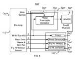
- FIG. 8depicts In an EAMR disk drive 200 ′.
- the EAMR disk drive 200 ′is analogous to the EAMR disk drive 200 .
- the EAMR disk drive 200 ′thus includes components having an analogous structure and function to components in the EAMR disk drive 200 .
- the EAMR disk drive 200 ′thus includes a pre-amplifier 212 ′, EAMR head(s) 220 ′, laser(s) 222 ′, clock recovery circuit(s) 230 ′, and EAMR transducer 240 ′ that are analogous to pre-amplifier 212 , EAMR head(s) 220 , laser(s) 222 , clock recovery circuit(s) 230 , and EAMR transducer 240 , respectively.
- Selected portions of the EAMR transducer 240 ′are also shown.
- coil(s) 242 , read sensor(s) 244 , fly height control heater(s) 246 , and fly height sensor(s) 248are shown. Additional components, such as poles, shields, and/or other structures are not shown for clarity.
- SOC 242 , clock 244 , and actuator flex 210 shown in FIGS. 6-7have been omitted in FIG. 8 .
- the clock recovery circuit(s) 230 ′include components 232 and 234 .
- the clock recovery circuit(s) 230 ′include a phase detector 232 and phase resettable oscillator 234 .
- the phase detector 232 and phase resettable oscillator 234form a phase locked loop.
- the phase detector 232includes inputs for the write gate signal, the laser control signal(s) generated by the clock recovery circuit 200 ′, and the write gate signal(s).
- the phase detector 232outputs a phase signal to the phase resettable oscillator 234 .
- the phase resettable oscillator 234receives an input from the write gate signal and the phase signal from the phase detector 232 .
- the phase resettable oscillator 234outputs the laser control signal to the laser 222 ′.
- the laser control signalis also fed back to the phase detector 232 .
- a phase locked loopis formed in the clock recovery circuit 230 ′.
- a buffer or other means for introducing a delaymay be used in the clock recovery circuit 230 ′ or elsewhere to match between the clock recovery circuit 230 ′ and the laser 222 ′ and the preamplifier 212 ′ and the writer coil(s) 242 .
- the laser control signalmay be carried on two lines from the pre-amplifier 212 ′ to the laser 222 ′. These lines may be a differential pair carrying pulses to the laser 222 ′ at twice the data rate of the write signal.
- the write signaluses two lines to carry write data.
- the read datamay also be carried on two lines.
- the heater signal and ground returns for the fly height control heater(s) 146may be carried on one or two lines.
- the fly height/touchdown sensor datais provided from the fly height sensor 148 on two lines.
- the phase lock loop formed by the phase detector 232 and phase resettable oscillator 234synchronizes the laser 222 ′ with the write signal to the coil(s) 242 .
- the laser 222 ′may be pulsed in time with the coil(s) 242 instead of driven continuously.
- higher peak energymay be used, without overheating the laser 222 ′. Consequently, performance of the EAMR disk drive 200 ′ may be enhanced.
- a single clock recovery circuit 200 ′may drive multiple EAMR heads 220 ′. Thus, less circuitry may be used per head 220 ′.
- delays between the clock recovery circuitry 230 ′ and the laser 222 ′are matched with delays between the pre-amplifier 212 ′ and the write coil(s) 242 .
- FIG. 9depicts In an EAMR disk drive 200 ′′.
- the EAMR disk drive 200 ′′is analogous to the EAMR disk drives 200 and 200 ′.
- the EAMR disk drive 200 ′′thus includes components having an analogous structure and function to components in the EAMR disk drive 200 .
- the EAMR disk drive 200 ′′thus includes a pre-amplifier 212 ′′, EAMR head(s) 220 ′′, laser(s) 222 ′′, clock recovery circuit(s) 230 ′′, and EAMR transducer 240 ′′ that are analogous to pre-amplifier 212 , EAMR head(s) 220 , laser(s) 222 , clock recovery circuit(s) 230 , and EAMR transducer 240 , respectively. Selected portions of the EAMR transducer 240 ′′ are also shown. For example, coil(s) 242 ′, read sensor(s) 244 ′, fly height control heater(s) 246 ′, and fly height sensor(s) 248 ′ are shown. Additional components, such as poles, shields, and/or other structures are not shown for clarity. For simplicity, SOC 242 , clock 244 , and actuator flex 210 shown in FIGS. 6-7 have been omitted in FIG. 9 .
- the clock recovery circuit(s) 230 ′′include phase resettable oscillator 234 ′.
- the phase detector 232 shown in FIG. 8has been omitted from the embodiment shown in FIG. 9 .
- the phase resettable oscillator 234 ′may be used alone in embodiments in which some downstream timing errors are acceptable.
- the phase resettable oscillator 234 ′receives an input from the write gate signal and from the write signal.
- the phase resettable oscillator 234 ′outputs the laser control signal to the laser 222 ′.
- a buffer or other means for introducing a delaymay be used in the clock recovery circuit 230 ′′ or elsewhere to match between the clock recovery circuit 230 ′′ and the laser 222 ′′ and the preamplifier 212 ′′ and the writer coil(s) 242 ′.
- the proposed number of lines between the pre-amplifier 212 ′′ and the EAMR head(s) 220 ′′may be used.
- the write gate signal and any power providedmay be carried on one line.
- the write signaluses two lines to carry write data.
- the read datamay also be carried on two lines.
- the heater signal and ground returns for the fly height control heater(s) 246 ′may be carried on two lines.
- the fly height/touchdown sensor datais provided from the fly height sensor 248 ′ on two lines.
- the phase resettable oscillator 234 ′synchronizes the laser 222 ′ with the write signal to the coil(s) 242 ′.
- the laser 222 ′′may be pulsed in time with the coil(s) 242 ′ instead of driven continuously.
- higher peak energymay be used without overheating the laser 222 ′′. Consequently, performance of the EAMR disk drive 200 ′′ may be enhanced.
- delays between the clock recovery circuitry 230 ′′ and the laser 222 ′′are matched with delays between the pre-amplifier 212 ′′ and the write coil(s) 242 ′.
- FIG. 10is a flow chart depicting an exemplary embodiment of a method 300 for writing to a media in an EAMR disk drive. Although certain steps are shown, some steps may be omitted, interleaved, performed in another order, and/or combined.
- the method 300is described in connection with the EAMR disk drives 100 and 200 . However, the method may be used with other disk drives including but not limited to the disk drives 100 ′, 100 ′′, 200 ′, and 200 ′′
- a write current signalis provided to the EAMR head 120 / 220 using a pre-amplifier 112 ′ 212 , via step 302 .
- the write signalhas a data rate and is used for energizing the writer coil(s) such as the coils 142 , 142 ′, 242 , and/or 242 ′.
- FIG. 11is a graph 310 depicting write signal 312 used to drive the EAMR transducer 140 / 240 and a laser control signal 314 used in driving the laser(s) 122 / 222 .
- the signals 312 and 314 shownare for explanatory purposes only and are not intended to represent a particular data set or embodiment. Referring to FIGS. 10 and 11 , the write data 312 may be bi-directional so that the coil(s) 142 / 142 ′/ 242 / 242 ′ may energize the pole in the desired direction.
- a write gate signalis provided to the EAMR head 120 / 220 using the pre-amplifier 112 / 212 , via step 304 .
- the write gate signalis used to drive the laser(s) 122 / 222 and to provide power to the EAMR head 120 / 220 .
- Laser control signal(s)are generated using clock recovery circuit(s) 130 / 230 coupled with the laser 122 / 222 , via step 306 .
- One embodiment of the laser control signal 314is shown in FIG. 11 . Because of the clock recovery circuit 130 / 230 , the laser control signal 314 is synchronized with the write current signal 312 . Stated differently, the laser control signal 314 energizes the laser 122 / 222 such that the laser 122 / 22 is energized synchronously with the writer coil(s) 142 / 142 ′/ 242 / 242 ′. As can be seen in the embodiment shown in FIG. 11 , the laser 122 / 222 is energized during the transitions of the write signal 312 .
- the data rate of the laser control signal 314is approximately twice that of the write signal 312 . Further, the laser control signal 314 straddles the transitions of the write signal 312 .
- the laser control signalmay be generated by a phase locked loop in the clock recovery circuit 130 ′/ 230 ′ or by a phase resettable oscillator 134 ′/ 234 .
- the laser 122 / 222may be driven synchronously with the coil(s) 142 / 142 ′/ 242 / 242 ′.
- higher peak energymay while maintaining or reducing heat generated. Consequently, performance of the EAMR disk drive 100 / 200 may be enhanced.
Landscapes
- Engineering & Computer Science (AREA)
- Signal Processing (AREA)
- Digital Magnetic Recording (AREA)
- Recording Or Reproducing By Magnetic Means (AREA)
- Magnetic Heads (AREA)
Abstract
Description
Claims (20)
Priority Applications (1)
| Application Number | Priority Date | Filing Date | Title |
|---|---|---|---|
| US12/973,957US8289821B1 (en) | 2010-12-21 | 2010-12-21 | Method and system for pulsing EAMR disk drives |
Applications Claiming Priority (1)
| Application Number | Priority Date | Filing Date | Title |
|---|---|---|---|
| US12/973,957US8289821B1 (en) | 2010-12-21 | 2010-12-21 | Method and system for pulsing EAMR disk drives |
Publications (1)
| Publication Number | Publication Date |
|---|---|
| US8289821B1true US8289821B1 (en) | 2012-10-16 |
Family
ID=46981770
Family Applications (1)
| Application Number | Title | Priority Date | Filing Date |
|---|---|---|---|
| US12/973,957Active2030-12-23US8289821B1 (en) | 2010-12-21 | 2010-12-21 | Method and system for pulsing EAMR disk drives |
Country Status (1)
| Country | Link |
|---|---|
| US (1) | US8289821B1 (en) |
Cited By (147)
| Publication number | Priority date | Publication date | Assignee | Title |
|---|---|---|---|---|
| US20120250180A1 (en)* | 2011-03-30 | 2012-10-04 | Kabushiki Kaisha Toshiba | Magnetic head |
| US20130083430A1 (en)* | 2011-09-30 | 2013-04-04 | Andrew Chiu | Multiple-sense thermo-resistive sensor for contact detection of read-write heads |
| US20130201577A1 (en)* | 2012-02-03 | 2013-08-08 | Seagate Technology Llc | Actively synchronizing magnetic responses of a shield and a write pole |
| US8830628B1 (en) | 2009-02-23 | 2014-09-09 | Western Digital (Fremont), Llc | Method and system for providing a perpendicular magnetic recording head |
| US8873201B2 (en) | 2012-02-03 | 2014-10-28 | Seagate Technology Llc | Low-recess write pole coil near shield at media-facing surface |
| US8879207B1 (en) | 2011-12-20 | 2014-11-04 | Western Digital (Fremont), Llc | Method for providing a side shield for a magnetic recording transducer using an air bridge |
| US8883017B1 (en) | 2013-03-12 | 2014-11-11 | Western Digital (Fremont), Llc | Method and system for providing a read transducer having seamless interfaces |
| US8891341B1 (en) | 2013-03-11 | 2014-11-18 | Western Digital Technologies, Inc. | Energy assisted magnetic recording disk drive using modulated laser light |
| US8917581B1 (en) | 2013-12-18 | 2014-12-23 | Western Digital Technologies, Inc. | Self-anneal process for a near field transducer and chimney in a hard disk drive assembly |
| US8923102B1 (en) | 2013-07-16 | 2014-12-30 | Western Digital (Fremont), Llc | Optical grating coupling for interferometric waveguides in heat assisted magnetic recording heads |
| US8929180B1 (en) | 2013-04-25 | 2015-01-06 | Western Digital Technologies, Inc. | Energy-assisted magnetic recording device having laser driving signal and magnetic write signal sharing same electrical conductor |
| US8947985B1 (en) | 2013-07-16 | 2015-02-03 | Western Digital (Fremont), Llc | Heat assisted magnetic recording transducers having a recessed pole |
| US8953422B1 (en) | 2014-06-10 | 2015-02-10 | Western Digital (Fremont), Llc | Near field transducer using dielectric waveguide core with fine ridge feature |
| US8958272B1 (en) | 2014-06-10 | 2015-02-17 | Western Digital (Fremont), Llc | Interfering near field transducer for energy assisted magnetic recording |
| US8971160B1 (en) | 2013-12-19 | 2015-03-03 | Western Digital (Fremont), Llc | Near field transducer with high refractive index pin for heat assisted magnetic recording |
| US8970988B1 (en) | 2013-12-31 | 2015-03-03 | Western Digital (Fremont), Llc | Electric gaps and method for making electric gaps for multiple sensor arrays |
| US8976635B1 (en) | 2014-06-10 | 2015-03-10 | Western Digital (Fremont), Llc | Near field transducer driven by a transverse electric waveguide for energy assisted magnetic recording |
| US8982508B1 (en) | 2011-10-31 | 2015-03-17 | Western Digital (Fremont), Llc | Method for providing a side shield for a magnetic recording transducer |
| US8980109B1 (en) | 2012-12-11 | 2015-03-17 | Western Digital (Fremont), Llc | Method for providing a magnetic recording transducer using a combined main pole and side shield CMP for a wraparound shield scheme |
| US8988812B1 (en) | 2013-11-27 | 2015-03-24 | Western Digital (Fremont), Llc | Multi-sensor array configuration for a two-dimensional magnetic recording (TDMR) operation |
| US8984740B1 (en) | 2012-11-30 | 2015-03-24 | Western Digital (Fremont), Llc | Process for providing a magnetic recording transducer having a smooth magnetic seed layer |
| US8988825B1 (en) | 2014-02-28 | 2015-03-24 | Western Digital (Fremont, LLC | Method for fabricating a magnetic writer having half-side shields |
| US8995087B1 (en) | 2006-11-29 | 2015-03-31 | Western Digital (Fremont), Llc | Perpendicular magnetic recording write head having a wrap around shield |
| US8993217B1 (en) | 2013-04-04 | 2015-03-31 | Western Digital (Fremont), Llc | Double exposure technique for high resolution disk imaging |
| US9001467B1 (en) | 2014-03-05 | 2015-04-07 | Western Digital (Fremont), Llc | Method for fabricating side shields in a magnetic writer |
| US8997832B1 (en) | 2010-11-23 | 2015-04-07 | Western Digital (Fremont), Llc | Method of fabricating micrometer scale components |
| US9001628B1 (en) | 2013-12-16 | 2015-04-07 | Western Digital (Fremont), Llc | Assistant waveguides for evaluating main waveguide coupling efficiency and diode laser alignment tolerances for hard disk |
| US9007719B1 (en) | 2013-10-23 | 2015-04-14 | Western Digital (Fremont), Llc | Systems and methods for using double mask techniques to achieve very small features |
| US9007879B1 (en) | 2014-06-10 | 2015-04-14 | Western Digital (Fremont), Llc | Interfering near field transducer having a wide metal bar feature for energy assisted magnetic recording |
| US9007725B1 (en) | 2014-10-07 | 2015-04-14 | Western Digital (Fremont), Llc | Sensor with positive coupling between dual ferromagnetic free layer laminates |
| US9013836B1 (en) | 2013-04-02 | 2015-04-21 | Western Digital (Fremont), Llc | Method and system for providing an antiferromagnetically coupled return pole |
| US9025420B1 (en)* | 2013-11-15 | 2015-05-05 | HGST Netherlands B.V. | Self-controlled laser pulsing for thermally assisted recording |
| US9042057B1 (en) | 2013-01-09 | 2015-05-26 | Western Digital (Fremont), Llc | Methods for providing magnetic storage elements with high magneto-resistance using Heusler alloys |
| US9042051B2 (en) | 2013-08-15 | 2015-05-26 | Western Digital (Fremont), Llc | Gradient write gap for perpendicular magnetic recording writer |
| US9042052B1 (en) | 2014-06-23 | 2015-05-26 | Western Digital (Fremont), Llc | Magnetic writer having a partially shunted coil |
| US9042058B1 (en) | 2013-10-17 | 2015-05-26 | Western Digital Technologies, Inc. | Shield designed for middle shields in a multiple sensor array |
| US9042208B1 (en) | 2013-03-11 | 2015-05-26 | Western Digital Technologies, Inc. | Disk drive measuring fly height by applying a bias voltage to an electrically insulated write component of a head |
| US9053735B1 (en) | 2014-06-20 | 2015-06-09 | Western Digital (Fremont), Llc | Method for fabricating a magnetic writer using a full-film metal planarization |
| US9064528B1 (en) | 2013-05-17 | 2015-06-23 | Western Digital Technologies, Inc. | Interferometric waveguide usable in shingled heat assisted magnetic recording in the absence of a near-field transducer |
| US9064507B1 (en) | 2009-07-31 | 2015-06-23 | Western Digital (Fremont), Llc | Magnetic etch-stop layer for magnetoresistive read heads |
| US9064527B1 (en) | 2013-04-12 | 2015-06-23 | Western Digital (Fremont), Llc | High order tapered waveguide for use in a heat assisted magnetic recording head |
| US9065043B1 (en) | 2012-06-29 | 2015-06-23 | Western Digital (Fremont), Llc | Tunnel magnetoresistance read head with narrow shield-to-shield spacing |
| US9064525B2 (en) | 2013-11-26 | 2015-06-23 | Western Digital Technologies, Inc. | Disk drive comprising laser transmission line optimized for heat assisted magnetic recording |
| US9070381B1 (en) | 2013-04-12 | 2015-06-30 | Western Digital (Fremont), Llc | Magnetic recording read transducer having a laminated free layer |
| US9082423B1 (en) | 2013-12-18 | 2015-07-14 | Western Digital (Fremont), Llc | Magnetic recording write transducer having an improved trailing surface profile |
| US9087534B1 (en) | 2011-12-20 | 2015-07-21 | Western Digital (Fremont), Llc | Method and system for providing a read transducer having soft and hard magnetic bias structures |
| US9087527B1 (en) | 2014-10-28 | 2015-07-21 | Western Digital (Fremont), Llc | Apparatus and method for middle shield connection in magnetic recording transducers |
| US9093639B2 (en) | 2012-02-21 | 2015-07-28 | Western Digital (Fremont), Llc | Methods for manufacturing a magnetoresistive structure utilizing heating and cooling |
| US9104107B1 (en) | 2013-04-03 | 2015-08-11 | Western Digital (Fremont), Llc | DUV photoresist process |
| US9111558B1 (en) | 2014-03-14 | 2015-08-18 | Western Digital (Fremont), Llc | System and method of diffractive focusing of light in a waveguide |
| US9111550B1 (en) | 2014-12-04 | 2015-08-18 | Western Digital (Fremont), Llc | Write transducer having a magnetic buffer layer spaced between a side shield and a write pole by non-magnetic layers |
| US9111564B1 (en) | 2013-04-02 | 2015-08-18 | Western Digital (Fremont), Llc | Magnetic recording writer having a main pole with multiple flare angles |
| US9123358B1 (en) | 2012-06-11 | 2015-09-01 | Western Digital (Fremont), Llc | Conformal high moment side shield seed layer for perpendicular magnetic recording writer |
| US9123374B1 (en) | 2015-02-12 | 2015-09-01 | Western Digital (Fremont), Llc | Heat assisted magnetic recording writer having an integrated polarization rotation plate |
| US9123362B1 (en) | 2011-03-22 | 2015-09-01 | Western Digital (Fremont), Llc | Methods for assembling an electrically assisted magnetic recording (EAMR) head |
| US9123355B1 (en) | 2013-09-16 | 2015-09-01 | Seagate Technology Llc | HAMR channel to preamp interface |
| US9123359B1 (en) | 2010-12-22 | 2015-09-01 | Western Digital (Fremont), Llc | Magnetic recording transducer with sputtered antiferromagnetic coupling trilayer between plated ferromagnetic shields and method of fabrication |
| US9135930B1 (en) | 2014-03-06 | 2015-09-15 | Western Digital (Fremont), Llc | Method for fabricating a magnetic write pole using vacuum deposition |
| US9135937B1 (en) | 2014-05-09 | 2015-09-15 | Western Digital (Fremont), Llc | Current modulation on laser diode for energy assisted magnetic recording transducer |
| US9142233B1 (en) | 2014-02-28 | 2015-09-22 | Western Digital (Fremont), Llc | Heat assisted magnetic recording writer having a recessed pole |
| US9147408B1 (en) | 2013-12-19 | 2015-09-29 | Western Digital (Fremont), Llc | Heated AFM layer deposition and cooling process for TMR magnetic recording sensor with high pinning field |
| US9147404B1 (en) | 2015-03-31 | 2015-09-29 | Western Digital (Fremont), Llc | Method and system for providing a read transducer having a dual free layer |
| US20150279430A1 (en)* | 2014-03-31 | 2015-10-01 | Seagate Technology Llc | Hamr drive fault detection system |
| US9153255B1 (en) | 2014-03-05 | 2015-10-06 | Western Digital (Fremont), Llc | Method for fabricating a magnetic writer having an asymmetric gap and shields |
| US9159349B2 (en) | 2013-08-28 | 2015-10-13 | Seagate Technology Llc | Writer core incorporating thermal sensor having a temperature coefficient of resistance |
| US9183854B2 (en) | 2014-02-24 | 2015-11-10 | Western Digital (Fremont), Llc | Method to make interferometric taper waveguide for HAMR light delivery |
| US9190085B1 (en) | 2014-03-12 | 2015-11-17 | Western Digital (Fremont), Llc | Waveguide with reflective grating for localized energy intensity |
| US9190079B1 (en) | 2014-09-22 | 2015-11-17 | Western Digital (Fremont), Llc | Magnetic write pole having engineered radius of curvature and chisel angle profiles |
| US9194692B1 (en) | 2013-12-06 | 2015-11-24 | Western Digital (Fremont), Llc | Systems and methods for using white light interferometry to measure undercut of a bi-layer structure |
| US9202480B2 (en) | 2009-10-14 | 2015-12-01 | Western Digital (Fremont), LLC. | Double patterning hard mask for damascene perpendicular magnetic recording (PMR) writer |
| US9202493B1 (en) | 2014-02-28 | 2015-12-01 | Western Digital (Fremont), Llc | Method of making an ultra-sharp tip mode converter for a HAMR head |
| US9214172B2 (en) | 2013-10-23 | 2015-12-15 | Western Digital (Fremont), Llc | Method of manufacturing a magnetic read head |
| US9214165B1 (en) | 2014-12-18 | 2015-12-15 | Western Digital (Fremont), Llc | Magnetic writer having a gradient in saturation magnetization of the shields |
| US9214169B1 (en) | 2014-06-20 | 2015-12-15 | Western Digital (Fremont), Llc | Magnetic recording read transducer having a laminated free layer |
| US9213322B1 (en) | 2012-08-16 | 2015-12-15 | Western Digital (Fremont), Llc | Methods for providing run to run process control using a dynamic tuner |
| US9230565B1 (en) | 2014-06-24 | 2016-01-05 | Western Digital (Fremont), Llc | Magnetic shield for magnetic recording head |
| US9236560B1 (en) | 2014-12-08 | 2016-01-12 | Western Digital (Fremont), Llc | Spin transfer torque tunneling magnetoresistive device having a laminated free layer with perpendicular magnetic anisotropy |
| US9245543B1 (en) | 2010-06-25 | 2016-01-26 | Western Digital (Fremont), Llc | Method for providing an energy assisted magnetic recording head having a laser integrally mounted to the slider |
| US9245545B1 (en) | 2013-04-12 | 2016-01-26 | Wester Digital (Fremont), Llc | Short yoke length coils for magnetic heads in disk drives |
| US9245562B1 (en) | 2015-03-30 | 2016-01-26 | Western Digital (Fremont), Llc | Magnetic recording writer with a composite main pole |
| US9251813B1 (en) | 2009-04-19 | 2016-02-02 | Western Digital (Fremont), Llc | Method of making a magnetic recording head |
| US9263071B1 (en) | 2015-03-31 | 2016-02-16 | Western Digital (Fremont), Llc | Flat NFT for heat assisted magnetic recording |
| US9263067B1 (en) | 2013-05-29 | 2016-02-16 | Western Digital (Fremont), Llc | Process for making PMR writer with constant side wall angle |
| US9269382B1 (en) | 2012-06-29 | 2016-02-23 | Western Digital (Fremont), Llc | Method and system for providing a read transducer having improved pinning of the pinned layer at higher recording densities |
| US9275657B1 (en) | 2013-08-14 | 2016-03-01 | Western Digital (Fremont), Llc | Process for making PMR writer with non-conformal side gaps |
| US9280990B1 (en) | 2013-12-11 | 2016-03-08 | Western Digital (Fremont), Llc | Method for fabricating a magnetic writer using multiple etches |
| US9281005B2 (en) | 2014-05-01 | 2016-03-08 | Avago Technologies General Ip (Singapore) Pte. Ltd. | Multiplexed communication in a storage device |
| US9286919B1 (en) | 2014-12-17 | 2016-03-15 | Western Digital (Fremont), Llc | Magnetic writer having a dual side gap |
| US9287494B1 (en) | 2013-06-28 | 2016-03-15 | Western Digital (Fremont), Llc | Magnetic tunnel junction (MTJ) with a magnesium oxide tunnel barrier |
| US9305583B1 (en) | 2014-02-18 | 2016-04-05 | Western Digital (Fremont), Llc | Method for fabricating a magnetic writer using multiple etches of damascene materials |
| US9312064B1 (en) | 2015-03-02 | 2016-04-12 | Western Digital (Fremont), Llc | Method to fabricate a magnetic head including ion milling of read gap using dual layer hard mask |
| US9318130B1 (en) | 2013-07-02 | 2016-04-19 | Western Digital (Fremont), Llc | Method to fabricate tunneling magnetic recording heads with extended pinned layer |
| US9336814B1 (en) | 2013-03-12 | 2016-05-10 | Western Digital (Fremont), Llc | Inverse tapered waveguide for use in a heat assisted magnetic recording head |
| US9343103B2 (en) | 2014-07-11 | 2016-05-17 | Avago Technologies General Ip (Singapore) Pte. Ltd. | Serial port communication for storage device using single bidirectional serial data line |
| US9343098B1 (en) | 2013-08-23 | 2016-05-17 | Western Digital (Fremont), Llc | Method for providing a heat assisted magnetic recording transducer having protective pads |
| US9343086B1 (en) | 2013-09-11 | 2016-05-17 | Western Digital (Fremont), Llc | Magnetic recording write transducer having an improved sidewall angle profile |
| US9343087B1 (en) | 2014-12-21 | 2016-05-17 | Western Digital (Fremont), Llc | Method for fabricating a magnetic writer having half shields |
| US9349392B1 (en) | 2012-05-24 | 2016-05-24 | Western Digital (Fremont), Llc | Methods for improving adhesion on dielectric substrates |
| US9349394B1 (en) | 2013-10-18 | 2016-05-24 | Western Digital (Fremont), Llc | Method for fabricating a magnetic writer having a gradient side gap |
| US9361914B1 (en) | 2014-06-18 | 2016-06-07 | Western Digital (Fremont), Llc | Magnetic sensor with thin capping layer |
| US9361913B1 (en) | 2013-06-03 | 2016-06-07 | Western Digital (Fremont), Llc | Recording read heads with a multi-layer AFM layer methods and apparatuses |
| US9368134B1 (en) | 2010-12-16 | 2016-06-14 | Western Digital (Fremont), Llc | Method and system for providing an antiferromagnetically coupled writer |
| US9384763B1 (en) | 2015-03-26 | 2016-07-05 | Western Digital (Fremont), Llc | Dual free layer magnetic reader having a rear bias structure including a soft bias layer |
| US9384765B1 (en) | 2015-09-24 | 2016-07-05 | Western Digital (Fremont), Llc | Method and system for providing a HAMR writer having improved optical efficiency |
| US9396742B1 (en) | 2012-11-30 | 2016-07-19 | Western Digital (Fremont), Llc | Magnetoresistive sensor for a magnetic storage system read head, and fabrication method thereof |
| US9396743B1 (en) | 2014-02-28 | 2016-07-19 | Western Digital (Fremont), Llc | Systems and methods for controlling soft bias thickness for tunnel magnetoresistance readers |
| US9406331B1 (en) | 2013-06-17 | 2016-08-02 | Western Digital (Fremont), Llc | Method for making ultra-narrow read sensor and read transducer device resulting therefrom |
| US9424866B1 (en) | 2015-09-24 | 2016-08-23 | Western Digital (Fremont), Llc | Heat assisted magnetic recording write apparatus having a dielectric gap |
| US9430148B2 (en) | 2014-05-01 | 2016-08-30 | Avago Technologies General Ip (Singapore) Pte. Ltd. | Multiplexed synchronous serial port communication with skew control for storage device |
| US9431038B1 (en) | 2015-06-29 | 2016-08-30 | Western Digital (Fremont), Llc | Method for fabricating a magnetic write pole having an improved sidewall angle profile |
| US9431032B1 (en) | 2013-08-14 | 2016-08-30 | Western Digital (Fremont), Llc | Electrical connection arrangement for a multiple sensor array usable in two-dimensional magnetic recording |
| US9431031B1 (en) | 2015-03-24 | 2016-08-30 | Western Digital (Fremont), Llc | System and method for magnetic transducers having multiple sensors and AFC shields |
| US9431039B1 (en) | 2013-05-21 | 2016-08-30 | Western Digital (Fremont), Llc | Multiple sensor array usable in two-dimensional magnetic recording |
| US9431047B1 (en) | 2013-05-01 | 2016-08-30 | Western Digital (Fremont), Llc | Method for providing an improved AFM reader shield |
| US9437251B1 (en) | 2014-12-22 | 2016-09-06 | Western Digital (Fremont), Llc | Apparatus and method having TDMR reader to reader shunts |
| US9441938B1 (en) | 2013-10-08 | 2016-09-13 | Western Digital (Fremont), Llc | Test structures for measuring near field transducer disc length |
| US9443541B1 (en) | 2015-03-24 | 2016-09-13 | Western Digital (Fremont), Llc | Magnetic writer having a gradient in saturation magnetization of the shields and return pole |
| US9449621B1 (en) | 2015-03-26 | 2016-09-20 | Western Digital (Fremont), Llc | Dual free layer magnetic reader having a rear bias structure having a high aspect ratio |
| US9449625B1 (en) | 2014-12-24 | 2016-09-20 | Western Digital (Fremont), Llc | Heat assisted magnetic recording head having a plurality of diffusion barrier layers |
| US9472216B1 (en) | 2015-09-23 | 2016-10-18 | Western Digital (Fremont), Llc | Differential dual free layer magnetic reader |
| US9484051B1 (en) | 2015-11-09 | 2016-11-01 | The Provost, Fellows, Foundation Scholars and the other members of Board, of the College of the Holy and Undivided Trinity of Queen Elizabeth near Dublin | Method and system for reducing undesirable reflections in a HAMR write apparatus |
| US9508365B1 (en) | 2015-06-24 | 2016-11-29 | Western Digital (Fremont), LLC. | Magnetic reader having a crystal decoupling structure |
| US9508363B1 (en) | 2014-06-17 | 2016-11-29 | Western Digital (Fremont), Llc | Method for fabricating a magnetic write pole having a leading edge bevel |
| US9508372B1 (en) | 2015-06-03 | 2016-11-29 | Western Digital (Fremont), Llc | Shingle magnetic writer having a low sidewall angle pole |
| US9530443B1 (en) | 2015-06-25 | 2016-12-27 | Western Digital (Fremont), Llc | Method for fabricating a magnetic recording device having a high aspect ratio structure |
| US9564150B1 (en) | 2015-11-24 | 2017-02-07 | Western Digital (Fremont), Llc | Magnetic read apparatus having an improved read sensor isolation circuit |
| US9595273B1 (en) | 2015-09-30 | 2017-03-14 | Western Digital (Fremont), Llc | Shingle magnetic writer having nonconformal shields |
| US9646639B2 (en) | 2015-06-26 | 2017-05-09 | Western Digital (Fremont), Llc | Heat assisted magnetic recording writer having integrated polarization rotation waveguides |
| US9666214B1 (en) | 2015-09-23 | 2017-05-30 | Western Digital (Fremont), Llc | Free layer magnetic reader that may have a reduced shield-to-shield spacing |
| US9697857B1 (en) | 2015-05-29 | 2017-07-04 | Seagate Technology Llc | Three dimensional data storage media |
| US9721595B1 (en) | 2014-12-04 | 2017-08-01 | Western Digital (Fremont), Llc | Method for providing a storage device |
| US9741366B1 (en) | 2014-12-18 | 2017-08-22 | Western Digital (Fremont), Llc | Method for fabricating a magnetic writer having a gradient in saturation magnetization of the shields |
| US9740805B1 (en) | 2015-12-01 | 2017-08-22 | Western Digital (Fremont), Llc | Method and system for detecting hotspots for photolithographically-defined devices |
| US9754611B1 (en) | 2015-11-30 | 2017-09-05 | Western Digital (Fremont), Llc | Magnetic recording write apparatus having a stepped conformal trailing shield |
| US9767831B1 (en) | 2015-12-01 | 2017-09-19 | Western Digital (Fremont), Llc | Magnetic writer having convex trailing surface pole and conformal write gap |
| US9786301B1 (en) | 2014-12-02 | 2017-10-10 | Western Digital (Fremont), Llc | Apparatuses and methods for providing thin shields in a multiple sensor array |
| US9799351B1 (en) | 2015-11-30 | 2017-10-24 | Western Digital (Fremont), Llc | Short yoke length writer having assist coils |
| US9799362B1 (en) | 2015-05-29 | 2017-10-24 | Seagate Technology Llc | Three dimensional data storage medium with a tuned recording layer |
| US9812155B1 (en) | 2015-11-23 | 2017-11-07 | Western Digital (Fremont), Llc | Method and system for fabricating high junction angle read sensors |
| US9842615B1 (en) | 2015-06-26 | 2017-12-12 | Western Digital (Fremont), Llc | Magnetic reader having a nonmagnetic insertion layer for the pinning layer |
| US9858951B1 (en) | 2015-12-01 | 2018-01-02 | Western Digital (Fremont), Llc | Method for providing a multilayer AFM layer in a read sensor |
| US9881638B1 (en) | 2014-12-17 | 2018-01-30 | Western Digital (Fremont), Llc | Method for providing a near-field transducer (NFT) for a heat assisted magnetic recording (HAMR) device |
| US9934811B1 (en) | 2014-03-07 | 2018-04-03 | Western Digital (Fremont), Llc | Methods for controlling stray fields of magnetic features using magneto-elastic anisotropy |
| US9953670B1 (en) | 2015-11-10 | 2018-04-24 | Western Digital (Fremont), Llc | Method and system for providing a HAMR writer including a multi-mode interference device |
| US10037770B1 (en) | 2015-11-12 | 2018-07-31 | Western Digital (Fremont), Llc | Method for providing a magnetic recording write apparatus having a seamless pole |
| US10074387B1 (en) | 2014-12-21 | 2018-09-11 | Western Digital (Fremont), Llc | Method and system for providing a read transducer having symmetric antiferromagnetically coupled shields |
| US20240331729A1 (en)* | 2023-03-30 | 2024-10-03 | Western Digital Technologies, Inc. | Data storage device with intelligent write protection for energy anomalies in energy-assisted magnetic recording |
Citations (19)
| Publication number | Priority date | Publication date | Assignee | Title |
|---|---|---|---|---|
| US4080576A (en) | 1976-01-08 | 1978-03-21 | Sperry Rand Corporation | Tow mode harmonic and nonharmonic phase detector |
| US4122501A (en) | 1976-12-13 | 1978-10-24 | Sperry Rand Corporation | System for recording and reading back data on a recording media |
| US20010055355A1 (en)* | 2000-06-26 | 2001-12-27 | Matsushita Electric Industrial Co., Ltd. | Clock recovery circuit |
| US20020003847A1 (en)* | 2000-07-06 | 2002-01-10 | Matsushita Electric Industrial Co., Ltd. | Clock recovery circuit |
| US20020006007A1 (en)* | 1999-06-02 | 2002-01-17 | Mehran Ataee | Method and apparatus for parking a read/write head during power interruptions by dynamic sequencing |
| US6801240B2 (en) | 2001-04-12 | 2004-10-05 | Ricoh Company, Ltd. | Information recording with effective pulse control scheme |
| US20060132957A1 (en)* | 2002-08-09 | 2006-06-22 | Takehiko Hamaguchi | Magnetic disk apparatus having an adjustable mechanism to compensate write or heat element for off-tracking position with yaw angle |
| US7242651B2 (en)* | 2000-12-11 | 2007-07-10 | Sanyo Electric Co., Ltd. | Disk reproduction device |
| US20070206649A1 (en) | 2006-03-03 | 2007-09-06 | Agency For Science, Technology And Research | High repetition rate laser module |
| US7317665B2 (en) | 2003-11-07 | 2008-01-08 | Hitachi, Ltd. | Optical recording method using multiplexer and plural pieces of data bits |
| US20080024896A1 (en)* | 2006-07-27 | 2008-01-31 | Tdk Corporation | Heat-assisted magnetic recording method using eddy current and head for heat-assisted magnetic recording |
| US20080037382A1 (en)* | 2001-05-14 | 2008-02-14 | Matsushita Electric Industrial Co., Ltd. | Optical Recording Medium Having a Control Layer |
| US20080107423A1 (en)* | 2006-11-06 | 2008-05-08 | Electronics And Telecommunications Research Institute | Optical transceiver and method of controlling optical output jitter using the same |
| US20090003835A1 (en)* | 2007-06-28 | 2009-01-01 | Oki Electric Industry Co., Ltd. | Optical clock recovery apparatus and method and birefringent medium |
| US7538978B2 (en) | 2004-12-28 | 2009-05-26 | Tdk Corporation | Heat assisted magnetic recording head and heat assisted magnetic recording apparatus for heating a recording region in a magnetic recording medium during magnetic recording |
| US20090296256A1 (en) | 2008-05-29 | 2009-12-03 | Fujitsu Limited | Thermal-assist magnetic recording device and thermal-assist magnetic storage device |
| US20100232053A1 (en)* | 2009-03-13 | 2010-09-16 | Kabushiki Kaisha Toshiba | Method and apparatus for controlling head with spin-torque oscillator in a disk drive |
| US20110116184A1 (en)* | 2009-11-17 | 2011-05-19 | Hitachi Global Storage Technologies Netherlands B.V. | Magnetic head having a multilayer magnetic film and method for producing the same |
| US20110228653A1 (en)* | 2010-03-22 | 2011-09-22 | Tdk Corporation | Light source unit for thermally-assisted magnetic recording capable of monitoring of light output |
- 2010
- 2010-12-21USUS12/973,957patent/US8289821B1/enactiveActive
Patent Citations (19)
| Publication number | Priority date | Publication date | Assignee | Title |
|---|---|---|---|---|
| US4080576A (en) | 1976-01-08 | 1978-03-21 | Sperry Rand Corporation | Tow mode harmonic and nonharmonic phase detector |
| US4122501A (en) | 1976-12-13 | 1978-10-24 | Sperry Rand Corporation | System for recording and reading back data on a recording media |
| US20020006007A1 (en)* | 1999-06-02 | 2002-01-17 | Mehran Ataee | Method and apparatus for parking a read/write head during power interruptions by dynamic sequencing |
| US20010055355A1 (en)* | 2000-06-26 | 2001-12-27 | Matsushita Electric Industrial Co., Ltd. | Clock recovery circuit |
| US20020003847A1 (en)* | 2000-07-06 | 2002-01-10 | Matsushita Electric Industrial Co., Ltd. | Clock recovery circuit |
| US7242651B2 (en)* | 2000-12-11 | 2007-07-10 | Sanyo Electric Co., Ltd. | Disk reproduction device |
| US6801240B2 (en) | 2001-04-12 | 2004-10-05 | Ricoh Company, Ltd. | Information recording with effective pulse control scheme |
| US20080037382A1 (en)* | 2001-05-14 | 2008-02-14 | Matsushita Electric Industrial Co., Ltd. | Optical Recording Medium Having a Control Layer |
| US20060132957A1 (en)* | 2002-08-09 | 2006-06-22 | Takehiko Hamaguchi | Magnetic disk apparatus having an adjustable mechanism to compensate write or heat element for off-tracking position with yaw angle |
| US7317665B2 (en) | 2003-11-07 | 2008-01-08 | Hitachi, Ltd. | Optical recording method using multiplexer and plural pieces of data bits |
| US7538978B2 (en) | 2004-12-28 | 2009-05-26 | Tdk Corporation | Heat assisted magnetic recording head and heat assisted magnetic recording apparatus for heating a recording region in a magnetic recording medium during magnetic recording |
| US20070206649A1 (en) | 2006-03-03 | 2007-09-06 | Agency For Science, Technology And Research | High repetition rate laser module |
| US20080024896A1 (en)* | 2006-07-27 | 2008-01-31 | Tdk Corporation | Heat-assisted magnetic recording method using eddy current and head for heat-assisted magnetic recording |
| US20080107423A1 (en)* | 2006-11-06 | 2008-05-08 | Electronics And Telecommunications Research Institute | Optical transceiver and method of controlling optical output jitter using the same |
| US20090003835A1 (en)* | 2007-06-28 | 2009-01-01 | Oki Electric Industry Co., Ltd. | Optical clock recovery apparatus and method and birefringent medium |
| US20090296256A1 (en) | 2008-05-29 | 2009-12-03 | Fujitsu Limited | Thermal-assist magnetic recording device and thermal-assist magnetic storage device |
| US20100232053A1 (en)* | 2009-03-13 | 2010-09-16 | Kabushiki Kaisha Toshiba | Method and apparatus for controlling head with spin-torque oscillator in a disk drive |
| US20110116184A1 (en)* | 2009-11-17 | 2011-05-19 | Hitachi Global Storage Technologies Netherlands B.V. | Magnetic head having a multilayer magnetic film and method for producing the same |
| US20110228653A1 (en)* | 2010-03-22 | 2011-09-22 | Tdk Corporation | Light source unit for thermally-assisted magnetic recording capable of monitoring of light output |
Non-Patent Citations (3)
| Title |
|---|
| W. A. Challener, et al, "The Road to HAMR", Magnetic Recording Conference, Jan. 2009, APMRC '09, Asia-Pacific, 14-16. |
| W. Don Huber and David A. Schmidt, "High Data Rate Magneto-Optical Recording", May 14, 2000-May 17, 2000, p. 126-128, Optical Data Storage 2000, Conference Digest. |
| W. Don Huber, et al, "Advanced Interconnect Design for High Data Rate Perpendicular Magnetic Recording", IEEE Trans. Mag., Jan. 2008, p. 175-180, vol. 44, No. 1. |
Cited By (171)
| Publication number | Priority date | Publication date | Assignee | Title |
|---|---|---|---|---|
| US8995087B1 (en) | 2006-11-29 | 2015-03-31 | Western Digital (Fremont), Llc | Perpendicular magnetic recording write head having a wrap around shield |
| US8830628B1 (en) | 2009-02-23 | 2014-09-09 | Western Digital (Fremont), Llc | Method and system for providing a perpendicular magnetic recording head |
| US9251813B1 (en) | 2009-04-19 | 2016-02-02 | Western Digital (Fremont), Llc | Method of making a magnetic recording head |
| US9064507B1 (en) | 2009-07-31 | 2015-06-23 | Western Digital (Fremont), Llc | Magnetic etch-stop layer for magnetoresistive read heads |
| US9202480B2 (en) | 2009-10-14 | 2015-12-01 | Western Digital (Fremont), LLC. | Double patterning hard mask for damascene perpendicular magnetic recording (PMR) writer |
| US9245543B1 (en) | 2010-06-25 | 2016-01-26 | Western Digital (Fremont), Llc | Method for providing an energy assisted magnetic recording head having a laser integrally mounted to the slider |
| US9672847B2 (en) | 2010-11-23 | 2017-06-06 | Western Digital (Fremont), Llc | Micrometer scale components |
| US8997832B1 (en) | 2010-11-23 | 2015-04-07 | Western Digital (Fremont), Llc | Method of fabricating micrometer scale components |
| US9159345B1 (en) | 2010-11-23 | 2015-10-13 | Western Digital (Fremont), Llc | Micrometer scale components |
| US9368134B1 (en) | 2010-12-16 | 2016-06-14 | Western Digital (Fremont), Llc | Method and system for providing an antiferromagnetically coupled writer |
| US9123359B1 (en) | 2010-12-22 | 2015-09-01 | Western Digital (Fremont), Llc | Magnetic recording transducer with sputtered antiferromagnetic coupling trilayer between plated ferromagnetic shields and method of fabrication |
| US9123362B1 (en) | 2011-03-22 | 2015-09-01 | Western Digital (Fremont), Llc | Methods for assembling an electrically assisted magnetic recording (EAMR) head |
| US8553358B2 (en)* | 2011-03-30 | 2013-10-08 | Kabushiki Kaisha Toshiba | Magnetic head |
| US20120250180A1 (en)* | 2011-03-30 | 2012-10-04 | Kabushiki Kaisha Toshiba | Magnetic head |
| US8854764B2 (en)* | 2011-09-30 | 2014-10-07 | HGST Netherlands B.V. | Multiple-sense thermo-resistive sensor for contact detection of read-write heads |
| US20130083430A1 (en)* | 2011-09-30 | 2013-04-04 | Andrew Chiu | Multiple-sense thermo-resistive sensor for contact detection of read-write heads |
| US8982508B1 (en) | 2011-10-31 | 2015-03-17 | Western Digital (Fremont), Llc | Method for providing a side shield for a magnetic recording transducer |
| US9087534B1 (en) | 2011-12-20 | 2015-07-21 | Western Digital (Fremont), Llc | Method and system for providing a read transducer having soft and hard magnetic bias structures |
| US8879207B1 (en) | 2011-12-20 | 2014-11-04 | Western Digital (Fremont), Llc | Method for providing a side shield for a magnetic recording transducer using an air bridge |
| US8873201B2 (en) | 2012-02-03 | 2014-10-28 | Seagate Technology Llc | Low-recess write pole coil near shield at media-facing surface |
| US8804280B2 (en)* | 2012-02-03 | 2014-08-12 | Seagate Technology Llc | Actively synchronizing magnetic responses of a shield and a write pole |
| US20130201577A1 (en)* | 2012-02-03 | 2013-08-08 | Seagate Technology Llc | Actively synchronizing magnetic responses of a shield and a write pole |
| US9093639B2 (en) | 2012-02-21 | 2015-07-28 | Western Digital (Fremont), Llc | Methods for manufacturing a magnetoresistive structure utilizing heating and cooling |
| US9940950B2 (en) | 2012-05-24 | 2018-04-10 | Western Digital (Fremont), Llc | Methods for improving adhesion on dielectric substrates |
| US9349392B1 (en) | 2012-05-24 | 2016-05-24 | Western Digital (Fremont), Llc | Methods for improving adhesion on dielectric substrates |
| US9123358B1 (en) | 2012-06-11 | 2015-09-01 | Western Digital (Fremont), Llc | Conformal high moment side shield seed layer for perpendicular magnetic recording writer |
| US9269382B1 (en) | 2012-06-29 | 2016-02-23 | Western Digital (Fremont), Llc | Method and system for providing a read transducer having improved pinning of the pinned layer at higher recording densities |
| US9065043B1 (en) | 2012-06-29 | 2015-06-23 | Western Digital (Fremont), Llc | Tunnel magnetoresistance read head with narrow shield-to-shield spacing |
| US9412400B2 (en) | 2012-06-29 | 2016-08-09 | Western Digital (Fremont), Llc | Tunnel magnetoresistance read head with narrow shield-to-shield spacing |
| US9213322B1 (en) | 2012-08-16 | 2015-12-15 | Western Digital (Fremont), Llc | Methods for providing run to run process control using a dynamic tuner |
| US9396742B1 (en) | 2012-11-30 | 2016-07-19 | Western Digital (Fremont), Llc | Magnetoresistive sensor for a magnetic storage system read head, and fabrication method thereof |
| US8984740B1 (en) | 2012-11-30 | 2015-03-24 | Western Digital (Fremont), Llc | Process for providing a magnetic recording transducer having a smooth magnetic seed layer |
| US8980109B1 (en) | 2012-12-11 | 2015-03-17 | Western Digital (Fremont), Llc | Method for providing a magnetic recording transducer using a combined main pole and side shield CMP for a wraparound shield scheme |
| US9042057B1 (en) | 2013-01-09 | 2015-05-26 | Western Digital (Fremont), Llc | Methods for providing magnetic storage elements with high magneto-resistance using Heusler alloys |
| US9042208B1 (en) | 2013-03-11 | 2015-05-26 | Western Digital Technologies, Inc. | Disk drive measuring fly height by applying a bias voltage to an electrically insulated write component of a head |
| US8891341B1 (en) | 2013-03-11 | 2014-11-18 | Western Digital Technologies, Inc. | Energy assisted magnetic recording disk drive using modulated laser light |
| US9336814B1 (en) | 2013-03-12 | 2016-05-10 | Western Digital (Fremont), Llc | Inverse tapered waveguide for use in a heat assisted magnetic recording head |
| US8883017B1 (en) | 2013-03-12 | 2014-11-11 | Western Digital (Fremont), Llc | Method and system for providing a read transducer having seamless interfaces |
| US9111564B1 (en) | 2013-04-02 | 2015-08-18 | Western Digital (Fremont), Llc | Magnetic recording writer having a main pole with multiple flare angles |
| US9013836B1 (en) | 2013-04-02 | 2015-04-21 | Western Digital (Fremont), Llc | Method and system for providing an antiferromagnetically coupled return pole |
| US9104107B1 (en) | 2013-04-03 | 2015-08-11 | Western Digital (Fremont), Llc | DUV photoresist process |
| US8993217B1 (en) | 2013-04-04 | 2015-03-31 | Western Digital (Fremont), Llc | Double exposure technique for high resolution disk imaging |
| US9070381B1 (en) | 2013-04-12 | 2015-06-30 | Western Digital (Fremont), Llc | Magnetic recording read transducer having a laminated free layer |
| US9064527B1 (en) | 2013-04-12 | 2015-06-23 | Western Digital (Fremont), Llc | High order tapered waveguide for use in a heat assisted magnetic recording head |
| US9245545B1 (en) | 2013-04-12 | 2016-01-26 | Wester Digital (Fremont), Llc | Short yoke length coils for magnetic heads in disk drives |
| US8929180B1 (en) | 2013-04-25 | 2015-01-06 | Western Digital Technologies, Inc. | Energy-assisted magnetic recording device having laser driving signal and magnetic write signal sharing same electrical conductor |
| US9431047B1 (en) | 2013-05-01 | 2016-08-30 | Western Digital (Fremont), Llc | Method for providing an improved AFM reader shield |
| US9064528B1 (en) | 2013-05-17 | 2015-06-23 | Western Digital Technologies, Inc. | Interferometric waveguide usable in shingled heat assisted magnetic recording in the absence of a near-field transducer |
| US9431039B1 (en) | 2013-05-21 | 2016-08-30 | Western Digital (Fremont), Llc | Multiple sensor array usable in two-dimensional magnetic recording |
| US9263067B1 (en) | 2013-05-29 | 2016-02-16 | Western Digital (Fremont), Llc | Process for making PMR writer with constant side wall angle |
| US9361913B1 (en) | 2013-06-03 | 2016-06-07 | Western Digital (Fremont), Llc | Recording read heads with a multi-layer AFM layer methods and apparatuses |
| US9406331B1 (en) | 2013-06-17 | 2016-08-02 | Western Digital (Fremont), Llc | Method for making ultra-narrow read sensor and read transducer device resulting therefrom |
| US9287494B1 (en) | 2013-06-28 | 2016-03-15 | Western Digital (Fremont), Llc | Magnetic tunnel junction (MTJ) with a magnesium oxide tunnel barrier |
| US9318130B1 (en) | 2013-07-02 | 2016-04-19 | Western Digital (Fremont), Llc | Method to fabricate tunneling magnetic recording heads with extended pinned layer |
| US8947985B1 (en) | 2013-07-16 | 2015-02-03 | Western Digital (Fremont), Llc | Heat assisted magnetic recording transducers having a recessed pole |
| US8923102B1 (en) | 2013-07-16 | 2014-12-30 | Western Digital (Fremont), Llc | Optical grating coupling for interferometric waveguides in heat assisted magnetic recording heads |
| US9431032B1 (en) | 2013-08-14 | 2016-08-30 | Western Digital (Fremont), Llc | Electrical connection arrangement for a multiple sensor array usable in two-dimensional magnetic recording |
| US9275657B1 (en) | 2013-08-14 | 2016-03-01 | Western Digital (Fremont), Llc | Process for making PMR writer with non-conformal side gaps |
| US9042051B2 (en) | 2013-08-15 | 2015-05-26 | Western Digital (Fremont), Llc | Gradient write gap for perpendicular magnetic recording writer |
| US9343098B1 (en) | 2013-08-23 | 2016-05-17 | Western Digital (Fremont), Llc | Method for providing a heat assisted magnetic recording transducer having protective pads |
| US9159349B2 (en) | 2013-08-28 | 2015-10-13 | Seagate Technology Llc | Writer core incorporating thermal sensor having a temperature coefficient of resistance |
| US9679598B2 (en) | 2013-08-28 | 2017-06-13 | Seagate Technology Llc | Writer core incorporating thermal sensor having a temperature coefficient of resistance |
| US9343086B1 (en) | 2013-09-11 | 2016-05-17 | Western Digital (Fremont), Llc | Magnetic recording write transducer having an improved sidewall angle profile |
| US9123355B1 (en) | 2013-09-16 | 2015-09-01 | Seagate Technology Llc | HAMR channel to preamp interface |
| US9441938B1 (en) | 2013-10-08 | 2016-09-13 | Western Digital (Fremont), Llc | Test structures for measuring near field transducer disc length |
| US9042058B1 (en) | 2013-10-17 | 2015-05-26 | Western Digital Technologies, Inc. | Shield designed for middle shields in a multiple sensor array |
| US9349394B1 (en) | 2013-10-18 | 2016-05-24 | Western Digital (Fremont), Llc | Method for fabricating a magnetic writer having a gradient side gap |
| US9214172B2 (en) | 2013-10-23 | 2015-12-15 | Western Digital (Fremont), Llc | Method of manufacturing a magnetic read head |
| US9830936B2 (en) | 2013-10-23 | 2017-11-28 | Western Digital (Fremont), Llc | Magnetic read head with antiferromagentic layer |
| US9007719B1 (en) | 2013-10-23 | 2015-04-14 | Western Digital (Fremont), Llc | Systems and methods for using double mask techniques to achieve very small features |
| US9025420B1 (en)* | 2013-11-15 | 2015-05-05 | HGST Netherlands B.V. | Self-controlled laser pulsing for thermally assisted recording |
| US20150138937A1 (en)* | 2013-11-15 | 2015-05-21 | HGST Netherlands B.V. | Self-controlled laser pulsing for thermally assisted recording |
| US9064525B2 (en) | 2013-11-26 | 2015-06-23 | Western Digital Technologies, Inc. | Disk drive comprising laser transmission line optimized for heat assisted magnetic recording |
| US8988812B1 (en) | 2013-11-27 | 2015-03-24 | Western Digital (Fremont), Llc | Multi-sensor array configuration for a two-dimensional magnetic recording (TDMR) operation |
| US9194692B1 (en) | 2013-12-06 | 2015-11-24 | Western Digital (Fremont), Llc | Systems and methods for using white light interferometry to measure undercut of a bi-layer structure |
| US9280990B1 (en) | 2013-12-11 | 2016-03-08 | Western Digital (Fremont), Llc | Method for fabricating a magnetic writer using multiple etches |
| US9001628B1 (en) | 2013-12-16 | 2015-04-07 | Western Digital (Fremont), Llc | Assistant waveguides for evaluating main waveguide coupling efficiency and diode laser alignment tolerances for hard disk |
| US9082423B1 (en) | 2013-12-18 | 2015-07-14 | Western Digital (Fremont), Llc | Magnetic recording write transducer having an improved trailing surface profile |
| US8917581B1 (en) | 2013-12-18 | 2014-12-23 | Western Digital Technologies, Inc. | Self-anneal process for a near field transducer and chimney in a hard disk drive assembly |
| US9147408B1 (en) | 2013-12-19 | 2015-09-29 | Western Digital (Fremont), Llc | Heated AFM layer deposition and cooling process for TMR magnetic recording sensor with high pinning field |
| US8971160B1 (en) | 2013-12-19 | 2015-03-03 | Western Digital (Fremont), Llc | Near field transducer with high refractive index pin for heat assisted magnetic recording |
| US8970988B1 (en) | 2013-12-31 | 2015-03-03 | Western Digital (Fremont), Llc | Electric gaps and method for making electric gaps for multiple sensor arrays |
| US9305583B1 (en) | 2014-02-18 | 2016-04-05 | Western Digital (Fremont), Llc | Method for fabricating a magnetic writer using multiple etches of damascene materials |
| US9183854B2 (en) | 2014-02-24 | 2015-11-10 | Western Digital (Fremont), Llc | Method to make interferometric taper waveguide for HAMR light delivery |
| US9202493B1 (en) | 2014-02-28 | 2015-12-01 | Western Digital (Fremont), Llc | Method of making an ultra-sharp tip mode converter for a HAMR head |
| US9142233B1 (en) | 2014-02-28 | 2015-09-22 | Western Digital (Fremont), Llc | Heat assisted magnetic recording writer having a recessed pole |
| US9396743B1 (en) | 2014-02-28 | 2016-07-19 | Western Digital (Fremont), Llc | Systems and methods for controlling soft bias thickness for tunnel magnetoresistance readers |
| US8988825B1 (en) | 2014-02-28 | 2015-03-24 | Western Digital (Fremont, LLC | Method for fabricating a magnetic writer having half-side shields |
| US9001467B1 (en) | 2014-03-05 | 2015-04-07 | Western Digital (Fremont), Llc | Method for fabricating side shields in a magnetic writer |
| US9349393B2 (en) | 2014-03-05 | 2016-05-24 | Western Digital (Fremont), Llc | Magnetic writer having an asymmetric gap and shields |
| US9153255B1 (en) | 2014-03-05 | 2015-10-06 | Western Digital (Fremont), Llc | Method for fabricating a magnetic writer having an asymmetric gap and shields |
| US9135930B1 (en) | 2014-03-06 | 2015-09-15 | Western Digital (Fremont), Llc | Method for fabricating a magnetic write pole using vacuum deposition |
| US9934811B1 (en) | 2014-03-07 | 2018-04-03 | Western Digital (Fremont), Llc | Methods for controlling stray fields of magnetic features using magneto-elastic anisotropy |
| US9495984B2 (en) | 2014-03-12 | 2016-11-15 | Western Digital (Fremont), Llc | Waveguide with reflective grating for localized energy intensity |
| US9190085B1 (en) | 2014-03-12 | 2015-11-17 | Western Digital (Fremont), Llc | Waveguide with reflective grating for localized energy intensity |
| US9111558B1 (en) | 2014-03-14 | 2015-08-18 | Western Digital (Fremont), Llc | System and method of diffractive focusing of light in a waveguide |
| US20150279430A1 (en)* | 2014-03-31 | 2015-10-01 | Seagate Technology Llc | Hamr drive fault detection system |
| US9318153B2 (en)* | 2014-03-31 | 2016-04-19 | Seagate Technology Llc | HAMR drive fault detection system |
| US9430148B2 (en) | 2014-05-01 | 2016-08-30 | Avago Technologies General Ip (Singapore) Pte. Ltd. | Multiplexed synchronous serial port communication with skew control for storage device |
| US9281005B2 (en) | 2014-05-01 | 2016-03-08 | Avago Technologies General Ip (Singapore) Pte. Ltd. | Multiplexed communication in a storage device |
| US9135937B1 (en) | 2014-05-09 | 2015-09-15 | Western Digital (Fremont), Llc | Current modulation on laser diode for energy assisted magnetic recording transducer |
| US8976635B1 (en) | 2014-06-10 | 2015-03-10 | Western Digital (Fremont), Llc | Near field transducer driven by a transverse electric waveguide for energy assisted magnetic recording |
| US8958272B1 (en) | 2014-06-10 | 2015-02-17 | Western Digital (Fremont), Llc | Interfering near field transducer for energy assisted magnetic recording |
| US9007879B1 (en) | 2014-06-10 | 2015-04-14 | Western Digital (Fremont), Llc | Interfering near field transducer having a wide metal bar feature for energy assisted magnetic recording |
| US9311952B2 (en) | 2014-06-10 | 2016-04-12 | Western Digital (Fremont), Llc | Interfering near field transducer for energy assisted magnetic recording |
| US8953422B1 (en) | 2014-06-10 | 2015-02-10 | Western Digital (Fremont), Llc | Near field transducer using dielectric waveguide core with fine ridge feature |
| US9159346B1 (en) | 2014-06-10 | 2015-10-13 | Western Digital (Fremont), Llc | Near field transducer using dielectric waveguide core with fine ridge feature |
| US9508363B1 (en) | 2014-06-17 | 2016-11-29 | Western Digital (Fremont), Llc | Method for fabricating a magnetic write pole having a leading edge bevel |
| US9361914B1 (en) | 2014-06-18 | 2016-06-07 | Western Digital (Fremont), Llc | Magnetic sensor with thin capping layer |
| US9214169B1 (en) | 2014-06-20 | 2015-12-15 | Western Digital (Fremont), Llc | Magnetic recording read transducer having a laminated free layer |
| US9053735B1 (en) | 2014-06-20 | 2015-06-09 | Western Digital (Fremont), Llc | Method for fabricating a magnetic writer using a full-film metal planarization |
| US9042052B1 (en) | 2014-06-23 | 2015-05-26 | Western Digital (Fremont), Llc | Magnetic writer having a partially shunted coil |
| US9230565B1 (en) | 2014-06-24 | 2016-01-05 | Western Digital (Fremont), Llc | Magnetic shield for magnetic recording head |
| US9343103B2 (en) | 2014-07-11 | 2016-05-17 | Avago Technologies General Ip (Singapore) Pte. Ltd. | Serial port communication for storage device using single bidirectional serial data line |
| US9190079B1 (en) | 2014-09-22 | 2015-11-17 | Western Digital (Fremont), Llc | Magnetic write pole having engineered radius of curvature and chisel angle profiles |
| US9007725B1 (en) | 2014-10-07 | 2015-04-14 | Western Digital (Fremont), Llc | Sensor with positive coupling between dual ferromagnetic free layer laminates |
| US9087527B1 (en) | 2014-10-28 | 2015-07-21 | Western Digital (Fremont), Llc | Apparatus and method for middle shield connection in magnetic recording transducers |
| US9786301B1 (en) | 2014-12-02 | 2017-10-10 | Western Digital (Fremont), Llc | Apparatuses and methods for providing thin shields in a multiple sensor array |
| US9721595B1 (en) | 2014-12-04 | 2017-08-01 | Western Digital (Fremont), Llc | Method for providing a storage device |
| US9111550B1 (en) | 2014-12-04 | 2015-08-18 | Western Digital (Fremont), Llc | Write transducer having a magnetic buffer layer spaced between a side shield and a write pole by non-magnetic layers |
| US9236560B1 (en) | 2014-12-08 | 2016-01-12 | Western Digital (Fremont), Llc | Spin transfer torque tunneling magnetoresistive device having a laminated free layer with perpendicular magnetic anisotropy |
| US9705072B2 (en) | 2014-12-08 | 2017-07-11 | Western Digital (Fremont), Llc | Spin transfer torque tunneling magnetoresistive device having a laminated free layer with perpendicular magnetic anisotropy |
| US9881638B1 (en) | 2014-12-17 | 2018-01-30 | Western Digital (Fremont), Llc | Method for providing a near-field transducer (NFT) for a heat assisted magnetic recording (HAMR) device |
| US9286919B1 (en) | 2014-12-17 | 2016-03-15 | Western Digital (Fremont), Llc | Magnetic writer having a dual side gap |
| US10553241B2 (en) | 2014-12-17 | 2020-02-04 | Western Digital Technologies, Inc. | Near-field transducer (NFT) for a heat assisted magnetic recording (HAMR) device |
| US9741366B1 (en) | 2014-12-18 | 2017-08-22 | Western Digital (Fremont), Llc | Method for fabricating a magnetic writer having a gradient in saturation magnetization of the shields |
| US9214165B1 (en) | 2014-12-18 | 2015-12-15 | Western Digital (Fremont), Llc | Magnetic writer having a gradient in saturation magnetization of the shields |
| US10074387B1 (en) | 2014-12-21 | 2018-09-11 | Western Digital (Fremont), Llc | Method and system for providing a read transducer having symmetric antiferromagnetically coupled shields |
| US9343087B1 (en) | 2014-12-21 | 2016-05-17 | Western Digital (Fremont), Llc | Method for fabricating a magnetic writer having half shields |
| US9437251B1 (en) | 2014-12-22 | 2016-09-06 | Western Digital (Fremont), Llc | Apparatus and method having TDMR reader to reader shunts |
| US9449625B1 (en) | 2014-12-24 | 2016-09-20 | Western Digital (Fremont), Llc | Heat assisted magnetic recording head having a plurality of diffusion barrier layers |
| US9123374B1 (en) | 2015-02-12 | 2015-09-01 | Western Digital (Fremont), Llc | Heat assisted magnetic recording writer having an integrated polarization rotation plate |
| US9312064B1 (en) | 2015-03-02 | 2016-04-12 | Western Digital (Fremont), Llc | Method to fabricate a magnetic head including ion milling of read gap using dual layer hard mask |
| US9754613B2 (en) | 2015-03-24 | 2017-09-05 | Western Digital (Fremont), Llc | Method for AFC shields for multiple sensor magnetic transducers and magnetic transducers having multiple sensors and AFC shields |
| US9431031B1 (en) | 2015-03-24 | 2016-08-30 | Western Digital (Fremont), Llc | System and method for magnetic transducers having multiple sensors and AFC shields |
| US9443541B1 (en) | 2015-03-24 | 2016-09-13 | Western Digital (Fremont), Llc | Magnetic writer having a gradient in saturation magnetization of the shields and return pole |
| US9384763B1 (en) | 2015-03-26 | 2016-07-05 | Western Digital (Fremont), Llc | Dual free layer magnetic reader having a rear bias structure including a soft bias layer |
| US9922672B1 (en) | 2015-03-26 | 2018-03-20 | Western Digital (Fremont), Llc | Dual free layer magnetic reader having a rear bias structure having a high aspect ratio |
| US9449621B1 (en) | 2015-03-26 | 2016-09-20 | Western Digital (Fremont), Llc | Dual free layer magnetic reader having a rear bias structure having a high aspect ratio |
| US9245562B1 (en) | 2015-03-30 | 2016-01-26 | Western Digital (Fremont), Llc | Magnetic recording writer with a composite main pole |
| US9263071B1 (en) | 2015-03-31 | 2016-02-16 | Western Digital (Fremont), Llc | Flat NFT for heat assisted magnetic recording |
| US9147404B1 (en) | 2015-03-31 | 2015-09-29 | Western Digital (Fremont), Llc | Method and system for providing a read transducer having a dual free layer |
| US9697857B1 (en) | 2015-05-29 | 2017-07-04 | Seagate Technology Llc | Three dimensional data storage media |
| US9799362B1 (en) | 2015-05-29 | 2017-10-24 | Seagate Technology Llc | Three dimensional data storage medium with a tuned recording layer |
| US9911446B1 (en) | 2015-05-29 | 2018-03-06 | Seagate Technology Llc | Three dimensional data storage media |
| US9508372B1 (en) | 2015-06-03 | 2016-11-29 | Western Digital (Fremont), Llc | Shingle magnetic writer having a low sidewall angle pole |
| US9508365B1 (en) | 2015-06-24 | 2016-11-29 | Western Digital (Fremont), LLC. | Magnetic reader having a crystal decoupling structure |
| US9530443B1 (en) | 2015-06-25 | 2016-12-27 | Western Digital (Fremont), Llc | Method for fabricating a magnetic recording device having a high aspect ratio structure |
| US10242700B2 (en) | 2015-06-26 | 2019-03-26 | Western Digital (Fremont), Llc | Magnetic reader having a nonmagnetic insertion layer for the pinning layer |
| US9842615B1 (en) | 2015-06-26 | 2017-12-12 | Western Digital (Fremont), Llc | Magnetic reader having a nonmagnetic insertion layer for the pinning layer |
| US9646639B2 (en) | 2015-06-26 | 2017-05-09 | Western Digital (Fremont), Llc | Heat assisted magnetic recording writer having integrated polarization rotation waveguides |
| US9431038B1 (en) | 2015-06-29 | 2016-08-30 | Western Digital (Fremont), Llc | Method for fabricating a magnetic write pole having an improved sidewall angle profile |
| US9666214B1 (en) | 2015-09-23 | 2017-05-30 | Western Digital (Fremont), Llc | Free layer magnetic reader that may have a reduced shield-to-shield spacing |
| US9472216B1 (en) | 2015-09-23 | 2016-10-18 | Western Digital (Fremont), Llc | Differential dual free layer magnetic reader |
| US9384765B1 (en) | 2015-09-24 | 2016-07-05 | Western Digital (Fremont), Llc | Method and system for providing a HAMR writer having improved optical efficiency |
| US9424866B1 (en) | 2015-09-24 | 2016-08-23 | Western Digital (Fremont), Llc | Heat assisted magnetic recording write apparatus having a dielectric gap |
| US9595273B1 (en) | 2015-09-30 | 2017-03-14 | Western Digital (Fremont), Llc | Shingle magnetic writer having nonconformal shields |
| US9484051B1 (en) | 2015-11-09 | 2016-11-01 | The Provost, Fellows, Foundation Scholars and the other members of Board, of the College of the Holy and Undivided Trinity of Queen Elizabeth near Dublin | Method and system for reducing undesirable reflections in a HAMR write apparatus |
| US10381029B2 (en) | 2015-11-10 | 2019-08-13 | Western Digital (Fremont), Llc | Method and system for providing a HAMR writer including a multi-mode interference device |
| US9953670B1 (en) | 2015-11-10 | 2018-04-24 | Western Digital (Fremont), Llc | Method and system for providing a HAMR writer including a multi-mode interference device |
| US10037770B1 (en) | 2015-11-12 | 2018-07-31 | Western Digital (Fremont), Llc | Method for providing a magnetic recording write apparatus having a seamless pole |
| US9812155B1 (en) | 2015-11-23 | 2017-11-07 | Western Digital (Fremont), Llc | Method and system for fabricating high junction angle read sensors |
| US9564150B1 (en) | 2015-11-24 | 2017-02-07 | Western Digital (Fremont), Llc | Magnetic read apparatus having an improved read sensor isolation circuit |
| US9799351B1 (en) | 2015-11-30 | 2017-10-24 | Western Digital (Fremont), Llc | Short yoke length writer having assist coils |
| US9754611B1 (en) | 2015-11-30 | 2017-09-05 | Western Digital (Fremont), Llc | Magnetic recording write apparatus having a stepped conformal trailing shield |
| US10121495B2 (en) | 2015-11-30 | 2018-11-06 | Western Digital (Fremont), Llc | Magnetic recording write apparatus having a stepped conformal trailing shield |
| US9740805B1 (en) | 2015-12-01 | 2017-08-22 | Western Digital (Fremont), Llc | Method and system for detecting hotspots for photolithographically-defined devices |
| US9858951B1 (en) | 2015-12-01 | 2018-01-02 | Western Digital (Fremont), Llc | Method for providing a multilayer AFM layer in a read sensor |
| US9997177B2 (en) | 2015-12-01 | 2018-06-12 | Western Digital (Fremont), Llc | Magnetic writer having convex trailing surface pole and conformal write gap |
| US9767831B1 (en) | 2015-12-01 | 2017-09-19 | Western Digital (Fremont), Llc | Magnetic writer having convex trailing surface pole and conformal write gap |
| US20240331729A1 (en)* | 2023-03-30 | 2024-10-03 | Western Digital Technologies, Inc. | Data storage device with intelligent write protection for energy anomalies in energy-assisted magnetic recording |
Similar Documents
| Publication | Publication Date | Title |
|---|---|---|
| US8289821B1 (en) | Method and system for pulsing EAMR disk drives | |
| US8027118B2 (en) | Method and apparatus for controlling head with spin-torque oscillator in a disk drive | |
| US8593914B2 (en) | Method and system for optically coupling a laser with a transducer in an energy assisted magnetic recording disk drive | |
| US8891340B2 (en) | Heat source management in data storage device | |
| US8233230B2 (en) | Method and apparatus for controlling head with spin-torque oscillator in a disk drive | |
| US8310901B1 (en) | Method and system for providing separate write and optical modules in an energy assisted magnetic recording disk drive | |
| JP4450032B2 (en) | Thermally assisted magnetic head, head gimbal assembly, and hard disk drive | |
| US8107325B2 (en) | Near-field light generating element comprising surface plasmon antenna with surface or edge opposed to waveguide | |
| US8274867B2 (en) | Method for aligning the light source unit and the slider of thermally-assisted magnetic recording head | |
| US8045422B2 (en) | Near-field light generating element comprising surface plasmon antenna and waveguide with groove | |
| EP2613317B1 (en) | Heat assisted magnetic recording system | |
| CN101673552B (en) | Magnetic recording disk drive | |
| US8804280B2 (en) | Actively synchronizing magnetic responses of a shield and a write pole | |
| US20120275279A1 (en) | Systems and Methods for Laser Write Control | |
| US8134792B2 (en) | Preamplifier and method for synchronization with bit patterned media | |
| US20140022876A1 (en) | Systems and Methods for Data Write Loopback Based Timing Control | |
| US8891341B1 (en) | Energy assisted magnetic recording disk drive using modulated laser light | |
| JP2008059694A (en) | Heat assisted magnetic head | |
| JP2008059697A (en) | Heat assisted magnetic head, head gimbal assembly, and hard disk drive | |
| JP2010020857A (en) | Magnetic recording head, magnetic head assembly and magnetic recording system | |
| US8611034B2 (en) | Microwave-assisted magnetic recording device and method using non-constant microwave | |
| JP2008210452A (en) | Thermal assist magnetic head, head gimbal assembly, and hard disk drive | |
| US8310902B1 (en) | Signal-extraction laser-pulse system architecture for thermally-assisted magnetic recording | |
| JP2013048001A (en) | Magnetic recording device | |
| US9245553B2 (en) | Submount-integrated photodetector for monitoring a laser for a heat-assisted magnetic recording head |
Legal Events
| Date | Code | Title | Description |
|---|---|---|---|
| AS | Assignment | Owner name:WESTERN DIGITAL (FREMONT), LLC, CALIFORNIA Free format text:ASSIGNMENT OF ASSIGNORS INTEREST;ASSIGNOR:HUBER, WILLIAM D.;REEL/FRAME:025536/0114 Effective date:20101221 | |
| STCF | Information on status: patent grant | Free format text:PATENTED CASE | |
| FPAY | Fee payment | Year of fee payment:4 | |
| AS | Assignment | Owner name:JPMORGAN CHASE BANK, N.A., AS COLLATERAL AGENT, IL Free format text:SECURITY AGREEMENT;ASSIGNOR:WESTERN DIGITAL (FREMONT), LLC;REEL/FRAME:038710/0845 Effective date:20160512 Owner name:JPMORGAN CHASE BANK, N.A., AS COLLATERAL AGENT, IL Free format text:SECURITY AGREEMENT;ASSIGNOR:WESTERN DIGITAL (FREMONT), LLC;REEL/FRAME:038744/0755 Effective date:20160512 Owner name:U.S. BANK NATIONAL ASSOCIATION, AS COLLATERAL AGEN Free format text:SECURITY AGREEMENT;ASSIGNOR:WESTERN DIGITAL (FREMONT), LLC;REEL/FRAME:038744/0675 Effective date:20160512 | |
| AS | Assignment | Owner name:WESTERN DIGITAL (FREMONT), LLC, CALIFORNIA Free format text:RELEASE BY SECURED PARTY;ASSIGNOR:U.S. BANK NATIONAL ASSOCIATION, AS COLLATERAL AGENT;REEL/FRAME:045501/0158 Effective date:20180227 | |
| AS | Assignment | Owner name:WESTERN DIGITAL TECHNOLOGIES, INC., CALIFORNIA Free format text:ASSIGNMENT OF ASSIGNORS INTEREST;ASSIGNOR:WESTERN DIGITAL (FREMONT), LLC;REEL/FRAME:050450/0582 Effective date:20190508 | |
| MAFP | Maintenance fee payment | Free format text:PAYMENT OF MAINTENANCE FEE, 8TH YEAR, LARGE ENTITY (ORIGINAL EVENT CODE: M1552); ENTITY STATUS OF PATENT OWNER: LARGE ENTITY Year of fee payment:8 | |
| AS | Assignment | Owner name:WESTERN DIGITAL TECHNOLOGIES, INC., CALIFORNIA Free format text:RELEASE OF SECURITY INTEREST AT REEL 038710 FRAME 0845;ASSIGNOR:JPMORGAN CHASE BANK, N.A.;REEL/FRAME:058965/0445 Effective date:20220203 Owner name:WESTERN DIGITAL (FREMONT), LLC, CALIFORNIA Free format text:RELEASE OF SECURITY INTEREST AT REEL 038710 FRAME 0845;ASSIGNOR:JPMORGAN CHASE BANK, N.A.;REEL/FRAME:058965/0445 Effective date:20220203 | |
| AS | Assignment | Owner name:JPMORGAN CHASE BANK, N.A., ILLINOIS Free format text:PATENT COLLATERAL AGREEMENT - A&R LOAN AGREEMENT;ASSIGNOR:WESTERN DIGITAL TECHNOLOGIES, INC.;REEL/FRAME:064715/0001 Effective date:20230818 Owner name:JPMORGAN CHASE BANK, N.A., ILLINOIS Free format text:PATENT COLLATERAL AGREEMENT - DDTL LOAN AGREEMENT;ASSIGNOR:WESTERN DIGITAL TECHNOLOGIES, INC.;REEL/FRAME:067045/0156 Effective date:20230818 | |
| FEPP | Fee payment procedure | Free format text:MAINTENANCE FEE REMINDER MAILED (ORIGINAL EVENT CODE: REM.); ENTITY STATUS OF PATENT OWNER: LARGE ENTITY | |
| FEPP | Fee payment procedure | Free format text:11.5 YR SURCHARGE- LATE PMT W/IN 6 MO, LARGE ENTITY (ORIGINAL EVENT CODE: M1556); ENTITY STATUS OF PATENT OWNER: LARGE ENTITY | |
| MAFP | Maintenance fee payment | Free format text:PAYMENT OF MAINTENANCE FEE, 12TH YEAR, LARGE ENTITY (ORIGINAL EVENT CODE: M1553); ENTITY STATUS OF PATENT OWNER: LARGE ENTITY Year of fee payment:12 |