US8289808B2 - System and method to estimate compressional to shear velocity (VP/VS) ratio in a region remote from a borehole - Google Patents
System and method to estimate compressional to shear velocity (VP/VS) ratio in a region remote from a boreholeDownload PDFInfo
- Publication number
- US8289808B2 US8289808B2US12/463,796US46379609AUS8289808B2US 8289808 B2US8289808 B2US 8289808B2US 46379609 AUS46379609 AUS 46379609AUS 8289808 B2US8289808 B2US 8289808B2
- Authority
- US
- United States
- Prior art keywords
- borehole
- frequency
- wave
- source
- sources
- Prior art date
- Legal status (The legal status is an assumption and is not a legal conclusion. Google has not performed a legal analysis and makes no representation as to the accuracy of the status listed.)
- Active, expires
Links
Images


Classifications
- G—PHYSICS
- G01—MEASURING; TESTING
- G01V—GEOPHYSICS; GRAVITATIONAL MEASUREMENTS; DETECTING MASSES OR OBJECTS; TAGS
- G01V1/00—Seismology; Seismic or acoustic prospecting or detecting
- G01V1/40—Seismology; Seismic or acoustic prospecting or detecting specially adapted for well-logging
- G01V1/44—Seismology; Seismic or acoustic prospecting or detecting specially adapted for well-logging using generators and receivers in the same well
- G—PHYSICS
- G01—MEASURING; TESTING
- G01V—GEOPHYSICS; GRAVITATIONAL MEASUREMENTS; DETECTING MASSES OR OBJECTS; TAGS
- G01V1/00—Seismology; Seismic or acoustic prospecting or detecting
- G01V1/003—Seismic data acquisition in general, e.g. survey design
- G01V1/006—Seismic data acquisition in general, e.g. survey design generating single signals by using more than one generator, e.g. beam steering or focusing arrays
- G—PHYSICS
- G01—MEASURING; TESTING
- G01V—GEOPHYSICS; GRAVITATIONAL MEASUREMENTS; DETECTING MASSES OR OBJECTS; TAGS
- G01V2210/00—Details of seismic processing or analysis
- G01V2210/10—Aspects of acoustic signal generation or detection
- G01V2210/12—Signal generation
- G01V2210/125—Virtual source
- G—PHYSICS
- G01—MEASURING; TESTING
- G01V—GEOPHYSICS; GRAVITATIONAL MEASUREMENTS; DETECTING MASSES OR OBJECTS; TAGS
- G01V2210/00—Details of seismic processing or analysis
- G01V2210/10—Aspects of acoustic signal generation or detection
- G01V2210/12—Signal generation
- G01V2210/127—Cooperating multiple sources
- G—PHYSICS
- G01—MEASURING; TESTING
- G01V—GEOPHYSICS; GRAVITATIONAL MEASUREMENTS; DETECTING MASSES OR OBJECTS; TAGS
- G01V2210/00—Details of seismic processing or analysis
- G01V2210/50—Corrections or adjustments related to wave propagation
- G01V2210/58—Media-related
- G01V2210/588—Non-linear media
Definitions
- the present inventionrelates generally to seismic interrogation of rock formations and more particularly to creating three-dimensional images of non-linear properties and the compressional to shear velocity ratio in a region remote from a borehole using a combination of sources in a borehole configured to provide elastic energy, and receiving and analyzing a resultant third wave formed by a three wave mixing process.
- a Logging While Drilling tooldesigned to detect rock formation boundaries, with two acoustic source arrays emitting from a borehole generating a third wave by assumed non-linear mixing in rocks at the location of intersection of the acoustic signals.
- the third waveis scattered by heterogeneities in subsurface properties, and the scattered signal is detected by sensors in the logging tool.
- the source arraysare merely disclosed to be directional without any further description.
- a method for creating three-dimensional images of non-linear properties in a region remote from a borehole using a conveyed logging toolincludes arranging with a specific spatial configuration a first source in the borehole and generating a steerable primary beam of elastic energy at a first frequency; arranging a second source in the borehole and generating a steerable primary beam of elastic energy at a second frequency, such that the two steerable beams intercept at a location away from the borehole; receiving by an array of sensors at the borehole the arrival of the third elastic wave, created by a three wave mixing process in the rock formation, with a frequency equal to a difference between the first and second primary frequencies, that propagates back to the borehole in a specific direction; locating the three wave mixing region based on the arrangement of the first and second sources and on the properties of the third wave signal; and creating three-dimensional images of the non-linear properties using data recorded by repeating the generating, receiving and locating steps at a plurality of
- a method for creating three-dimensional images of non-linear properties in a region remote from a borehole using a conveyed logging toolincludes arranging with a specific spatial configuration a first source in the borehole and generating a primary wave of elastic energy at a first frequency; arranging a second source in the borehole and generating a primary wave of elastic energy at a second frequency; receiving by an array of three component sensors at the borehole the arrival of the third elastic wave created by a three wave mixing process, with a frequency equal to a difference between the first and second primary frequencies, that propagates back to the borehole; determining the propagation direction of the third wave from the signals received by the sensor array; imaging the locus of the three wave mixing region based on the arrangement of the first and second sources and the propagation direction of the third wave; and creating three-dimensional images of the non-linear properties using data recorded by repeating the generating, receiving, determining and imaging steps at a plurality of azimuths, inclin
- further methods for creating three-dimensional images of non-linear properties in a region remote from a borehole using a conveyed logging toolare disclosed. These share the common configuration of two sources and an array of sensors in the borehole, but differ in that the one or other of the sources may generate a steerable beam or a wave of elastic energy, and the sensor units in the array may be a combination of non-directional and three component devices.
- the methodincludes arranging with a specific spatial configuration a first source in the borehole and generating either a steerable primary beam of elastic energy or a primary wave of elastic energy at a first frequency; arranging a second source in the borehole and generating either a steerable primary beam of elastic energy or a primary wave of elastic energy at a second frequency, such that the energy from the two sources mixes at locations away from the borehole; receiving by a sensor array at the borehole the direct arrival of the third elastic wave, created by a three wave mixing process, with a frequency equal to a difference between the first and second primary frequencies, that propagates back to the borehole in a specific direction; locating the three wave mixing region based on the arrangement of the first and second sources and on properties of the third wave signal; and creating three-dimensional images of the non-linear properties using data recorded by repeating the generating, receiving and locating steps at a plurality of azimuths, inclinations and longitudinal locations within the borehole.
- three dimensional images of the non-linear properties of the formations surrounding the boreholeare transformed to reservoir properties using appropriate relations between formation non-linearity and said properties.
- the imagesmay be of properties at the time of logging, or may represent changes between two logging runs separated by the passage of time.
- methods to create three dimensional images of the ratio of compressional to shear acoustic velocity of rocks surrounding the boreholeare disclosed. These methods are variations of the methods for creating three dimensional images of non-linear properties discussed above.
- an apparatus for creating three-dimensional images of non-linear properties and the compressional to shear velocity ratio of the rock formations remote from a borehole using a conveyed logging toolincludes a first source arranged in the borehole and configured to generate a steerable beam or a wave of elastic energy at a first frequency; a second source arranged in the borehole and configured to generate a steerable beam or a wave of elastic energy at a second frequency, such that the beams or waves at the first frequency and the second frequency intercept at a location away from the borehole; and a non-directional or three component sensor array configured to receive a third elastic wave if that the non-linear properties of the region of interest result in the creation of the third elastic wave by a three wave mixing process having a frequency equal to a difference of the first and the second frequencies and a specific direction of propagation back to the borehole; a first processor arranged in the borehole to control source firing and recording of the third elastic wave; a device configured
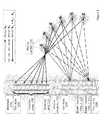
- FIG. 1shows a configuration for creating three-dimensional images of non-linear properties in a region remote from a borehole in accordance with various aspects of the disclosure
- FIG. 2shows a configuration for creating three-dimensional images of non-linear properties in a region remote from a borehole in accordance with aspects of the disclosure.
- FIG. 3shows a configuration for creating three-dimensional images of non-linear properties in a region remote from a borehole in accordance with aspects of the disclosure.
- FIG. 4shows a flow chart for creating three-dimensional images of non-linear properties in a region remote from a borehole in accordance with various aspects of the disclosure.
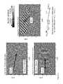
- FIGS. 5 a , 5 b and 5 cshows a numerical simulation of selection rule 1 for a beam-beam interaction of Table 1 when the two primary waves are beams.
- FIG. 6illustrates the geometry of the generation of the difference frequency third wave by non-linear mixing of two primary acoustic waves as governed by the non-linear mixing selection rule.
- FIG. 7shows an application of aspects of the disclosure for imaging using a beam and broad beam or plane wave.
- FIG. 1shows one of several possible configurations for creating three-dimensional images of non-linear properties and the compressional to shear velocity ratio in a region remote from a borehole in accordance with various aspects of the disclosure.
- First source 105is arranged in borehole 110 to generate a steerable primary beam of acoustic energy at a first frequency f 1 .
- Second source 115is also arranged in borehole 110 to generate a steerable primary beam of acoustic energy at a second frequency f 2 .
- both first source 105 and second source 115may be a phased array of sources and may be configured to generate either compressional or shear steerable beams.
- first source 105is arranged on first tool body 120 and second source 115 is arranged on second tool body 125 .
- first tool body 120 and second tool body 125may also be arranged together on a common tool body (not shown).
- Tool bodies 120 and 125are arranged to be independently moveable within bore hole 110 in at least two degrees of freedom including translation along the longitudinal axis 150 of borehole 110 and rotation 155 in azimuth about the longitudinal axis of borehole 110 .
- First source 105may be arranged above or below second source 115 in borehole 110 .
- Tool bodies 120 and 125may be arranged on a conveyed logging tool (not shown) within borehole 110 .
- the beam generated by second source 115 and the beam generated by first source 105are configured such that the beams converge and intercept in a mixing zones 130 remote from borehole 110 .
- the mixing zones 130move in the plane defined by the beams and the longitudinal borehole axis 150 , while controlling the angle of interception.
- the distance of mixing zones 130 from borehole 110can range from near the edge of borehole 110 to about 300 meters into the surrounding subsurface rock formation.
- the phase difference and/or time delays between adjacent elements in the source arraymay be modified to focus the acoustic energy of the primary beams at a particular mixing zone.
- the non-linear properties of the earth at the location between the two wavesresult in the generation of a third elastic wave.
- the third elastic waveis a result of a three-wave mixing process that occurs in nonlinear materials, in this case, rock formations.
- two converging non-collinear waves of different frequencies, f 1 and f 2also called primary waves, mix to form additional waves at the harmonic and intermodulation frequencies f 1 ⁇ f 2 , f 1 +f 2 , 2 ⁇ f 1 ; and 2 ⁇ f 2 , etc.
- the strength of the third waveis a function the non-linearity of the rocks in the mixing zones.
- a primary compressional (P) wave with a frequency f 1 and a primary shear (SV) wave with a frequency f 2cross in a non-linear medium
- a third compressional (P) or shear (SV) waveis generated with a frequency f 1 ⁇ f 2 .
- the third wave propagation vectoris co-planar with the propagation vectors of the two primary waves. Certain combinations of angle of intersection, f 1 /f 2 ratio and compressional to shear velocity ratio result in a third elastic wave with frequency f 1 ⁇ f 2 propagating in a specific angle relative to the primary beams back to the borehole 110 .
- Sensor or receiver array 135is arranged at specific location in borehole 110 to detect the third wave returning to the borehole 110 .
- sensor array 135comprises more than one sensor arranged as an array of sensors on sensor tool body 140 and separate from tool bodies 120 and 125 .
- Sensor 135is configured to be independently moveable within bore hole 110 along the longitudinal axis 150 of borehole 110 .
- sensor tool body 140is arranged below tool bodies 120 and 125 or arranged above and below tool bodies 120 and 125 .
- sensor tool body 140is connected to either or both tool bodies 120 and 125 .
- FIG. 2shows an arrangement similar to FIG. 1 , wherein receiver 135 is replaced by three component geophone 145 clamped to the borehole walls.
- the resultant signalis decomposed by processing into its inclination and azimuth in order to add redundancy to the system by determining the direction of the incoming third wave arrival.
- a first processorconfigured to execute machine-readable instructions (not shown) may be arranged in borehole 110 to perform various processing tasks, such as controlling source firing and compressing or filtering the data recorded by sensor array 135 .
- a second processorconfigured to execute machine-readable instructions (not shown) may be arranged outside borehole 110 to assist the first processor or perform different processing tasks than the first processor. For example, the second processor may perform part or all processing activities in creating the three-dimensional images.
- a transmitter or transceivermay be arranged in borehole 110 to transmit data up-hole through a wireline cable (not shown).
- FIG. 3shows another arrangement for creating three-dimensional images of non-linear properties in a region remote from a borehole in accordance with various aspects of the disclosure.
- the arrangement of FIG. 3is similar to the arrangement in FIG. 2 , with the primary difference being that the sources are arranged in borehole 110 to produce elastic waves instead of steerable beams.
- first source 305is arranged in borehole 110 on first tool body 320 to generate a first elastic wave of acoustic energy at a first frequency f 1 .
- Second source 315is arranged in borehole 110 on second tool body 325 to generate a second elastic wave of acoustic energy at a second frequency f 2 .
- First and second elastic waves produced by sources 305 , 315are arranged to intercept away from borehole 110 at various mixing zones 130 .
- Receiver 145is arranged within borehole 110 to receive a third wave that is produced in the mixing zones 130 by the three-wave mixing process discussed above, and further discussed below. Since the waves produced by sources 305 , 315 are essentially non-directional, mixing between the waves occurs simultaneously in the entire area of mixing zones 130 , that also extends out of the plane of the Figure, and receiver 145 tends to have directional characteristics.
- a three component geophone arraymay be used for this purpose.
- the resultant signalis decomposed by processing into multiple arrival signals at a range of inclinations and azimuths and travel times.
- FIG. 4shows a method for creating three-dimensional images of non-linear properties and the compressional to shear velocity ratio in a region remote from a borehole using a conveyed logging tool.
- the methodbegins at 405 where a first source is arranged in the borehole to generate a steerable beam elastic energy at a first frequency and a second source is arranged in the borehole to generate a steerable beam of elastic energy at a second frequency.
- the steerable beams at the first and second frequencyare arranged to intercept at a location away from the borehole.
- the second beamis generated at the same azimuth as the first beam, but at a different inclination relative to the longitudinal axis of the borehole.
- a third elastic waveis received at the borehole by a sensor array.
- the third elastic waveis created by a three wave mixing process, with a frequency equal to a difference between the first and second frequencies and a direction of propagation towards the borehole.
- a three wave mixing location away from the boreholeis determined from the arrangement of the first and second sources and properties of the third wave, by recourse to the selection rules discussed below.
- three-dimensional imagesare created of the non-linear properties using data recorded by repeating the generating of step 405 , the receiving of step 410 and the determining of step 415 at a plurality of azimuths, inclinations and longitudinal locations within the borehole.
- the received signalsare analyzed in step 425 for the compressional/shear velocity (Vp/Vs) ratio.
- Vp/Vscompressional/shear velocity
- the non-linear propertiesare transformed to physical reservoir properties such as fluid saturation, effective stress, fracture density and mineralogy.
- the first and second sourcesmay be beam or cylindrical or spherical wave sources
- the sensor arraymay be any combination of non-directional single component sensors and three component geophones.
- Alternative permutations of the component partsoffer different degrees of redundancy in signal processing and imaging.
- the selection ruleimposes a very tight restriction on the permissible crossing angles for the primary waves and a specific propagation direction of the third wave.
- the general kinematic theory for non-linear mixing of two linear plane waves and the selection rules and amplitude responseshave contributions from Jones and Kobett (1963), Rollins, Taylor et al.
- Equation 53 and 54 of Korneev, Nihei and Myershow that the mixing strength of P and SV (vertically polarized shear) plane waves is proportional to a specific combination of non-linear parameters of the rocks.
- FIGS. 5 a , 5 b and 5 cshows a numerical simulation of selection rule 1 of Table 1 when the two primary waves are beams of a beam-beam interaction.
- a 25 kHz compressional beam, shown in FIG. 5 a , and a 18 kHz shear beam, shown in FIG. 5 b , mix to form a third beam, shown in FIG. 5 c , with frequency 7 kHz25 kHz ⁇ 18 kHz.
- a third back propagating P beam with frequency (f 1 ⁇ f 2 ) at an angle of 133° to the P(f 1 ) waveis generated by nonlinear mixing in the region where the P(f 1 ) and SV(f 2 ) beams overlap.
- the kinematics of non-linear interactions of beamsresults in the generation of specific combinations of wave vectors and frequencies.
- k 1 and k 2there is a well-defined propagation wave vector k 3 of the third wave in the same plane, defined by k 1 and k 2 .
- the signal strength of the receiverwould be proportional to the strength of the non-linearity of the rocks in the mixing zone, among other factors, and reach a maximum for a receiver lying on vector k 3 . Therefore, the signal strength at the receivers can be geometrically mapped onto the non-linearity of the rocks along the beam trajectory as indicated by FIG. 1 .
- the geometrical theory of wave propagationindicates that the beam generated in each interaction zone would arrive at the borehole at a specific receiver defined by the geometry of the three wave vectors k 1 , k 2 and k 3 , after a specific time delay.
- the strength of the returning signal at a specific location in the borehole at a particular timeis dependent on the degree of non-linearity of the interaction location, and hence a time image of the relative strength of the non-linear properties of the rocks along the beam can be constructed.
- the amplitude magnitude of a returned signal at the receiversis itself indicative of certain petrophysical properties of the mixing zone.
- a localized circumferential and radial 3D image of non-linear properties of rocks surrounding the boreholecan be obtained.
- repeated 3D images of non-linear properties of rocks surrounding the boreholeare obtained.
- weighted stacks of these repeated imagesa final image of non-linear properties of rocks surrounding the entire borehole can be constructed through subsequent computer processing.
- the sources and the receiversare part of three separate tool bodies, one or two can be moved while the third one is fixed (for example, the sources are fixed while the receiver tool body is moved up and down). Alternatively, several descents into the well may be made with different spacing between the tool bodies.
- U2 ⁇ ⁇ 2 ⁇ ⁇ PS v ⁇ P ⁇ A 1 ⁇ B 2 ⁇ f 1 ⁇ f 2 ⁇ ( f 1 - f 2 ) V P 2 ⁇ V s ⁇ V PS v ⁇ P r ⁇ F PS v ⁇ P ⁇ ⁇ PS v ⁇ P ( 1 )
- Uis the displacement amplitude of the third wave received at the borehole
- a 1is the longitudinal polarization of the compressional wave
- B 2is the transverse polarization of the shear wave.
- ⁇is a function of the A, B and C parameters of Landau and Lifschitz representing the non-linearity of the rocks in the mixing zone.
- vis the volume of the mixing zone
- ris the distance from mixing zone to the receiver.
- Fis the geometric form factor of order 1 which is dependent on the geometry of the incident beams and can be numerically computed from the Korneev, Nihei, Myers theory for the particular geometry.
- Ais a selection rule form factor which is a numerically computable function of the wave vectors k 1 , k 2 and k 3 and is only significant if the interaction geometry honors the selection rules.
- the subscript PS v P in the formularefers to compressional-shear interaction generating a compressional wave.
- an image of the compressional to shear velocity ratiomay be constructed as follows.
- one of the sourcesgenerates a compressional wave (P-wave) with frequency f 1 and the other source generates an SV-wave with frequency f 2 and both waves are steered towards a specific mixing volume
- the direction of this third wavecan be determined and thereby, the in situ Vp/Vs of the mixing zone can be computed.
- the beam and plane waveare scanned in azimuth and inclination while preserving the necessary convergence angle, a localized circumferential and radial 3D image of in situ Vp/Vs ratio of rocks surrounding the borehole can be obtained.
- repeated 3D images of in situ Vp/Vs of rocks surrounding the boreholemay be obtained.
- a final image of in situ Vp/Vs of rocks surrounding the entire boreholecan be constructed through subsequent computer processing. Alternatively, several descents into the well may be made with different fixed spacing between the tool bodies.
- an alternative determination of Vp/Vs ratiois achieved through scanning the ratio of the frequencies f 1 to f 2 of the primary beams.
- FIG. 6illustrates the geometry of the interaction of two beams such as those generated in the configuration of FIG. 1 , that may be analyzed using the vector mathematics and trigonometry described above.
- the lengths k 1 and k 2 of vectors k 1 and k 2are defined by the ratio of their corresponding frequencies and velocities.
- the returning angle ⁇is a function of f 1 /f 2 , Vp/Vs ratio and the intersection angle ⁇ of the two primary beams.
- the physical selection rulesonly permit the generation of a third wave at specific combinations of f 1 /f 2 , Vp/Vs ratio and angle of interception 0, such as the example illustrated on FIG. 5 .
- the VpVs ratio of a 3D volume around the boreholeis interrogated and thereby 3D images of in situ Vp/Vs ratio of rocks surrounding the borehole may be obtained.
- the methods described aboveoffer an advantageous property in that the frequency difference f 1 ⁇ f 2 is very specific, allowing for spectral analysis to enhance the signal to noise ratio of the measurements. Moreover, if both frequencies f 1 and f 2 are simultaneously chirped proportionally, the resulting difference frequency signal f 1 ⁇ f 2 would also be a well defined chirped signal.
- the time-varying codemay include one or more of a variation in amplitude, a variation in frequency, and/or a variation in phase of the first, the second, or both the first and the second beams or waves.
- the third difference wavecan be broad band if one of the primary frequencies is swept through a range of frequencies while their frequency ratio is fixed. Thus, the resulting third beam f 2 ⁇ f 1 will be swept across a wide frequency range, while preserving the same direction. This allows for improvement in signal to noise by standard auto-correlation of the chirped or coded signal.
- the signal to noise discrimination of the recorded third wave from receivers 135can be enhanced further by employing three-component receivers in the borehole.
- the signals from the three componentscan be tuned to specific directivity by a technique, such as, hodogram analysis.
- the signal to noise ratiocan be improved by repeating the above steps with an inverse polarity (180 degrees out of phase) and adding the results together.
- the returning difference frequency signalwill add coherently as its amplitude is proportional to the product of the amplitudes of the two primary waves and therefore will not reverse polarity when the polarity of the primary source is reversed, while any linear noises generated by the primary waves in the system will reverse polarity and cancel upon addition.
- a method to generate images by computer processing of acoustic and seismic signalsincludes the follow steps. First, perform spectral analysis of the frequency content of the recorded third wave and applicable selection rules of the difference frequency signal in order to isolate the third wave signal generated by the non-linear mixing process. In the case that the sensors include three component geophones, determine the direction of the third wave impinging on the borehole using orientation techniques.
- the methodcontinues by analyzing the amplitude of the recorded third wave as a function of frequency ratios of the primary mixing waves and determining the mixing location where the third wave signals originated, from the selection rules of non-collinear mixing in non-linear media, the wavenumbers of the first and second beams and the third wave and the locations of the two beam sources and the sensor array.
- the methodcontinues by constructing seismograms determined by cross-correlation of the received signals with chirped transmitter signals for each source-receiver combination.
- the methodcontinues by performing three dimensional time or depth imaging to the entire data set, in order to obtain three dimensional images of the non-linear properties of the formation surrounding a borehole in either or both of time and distance.
- the methods for generating images from seismogramsare known, for example, Hill et al., which is hereby incorporated by reference, have provided the general methodology for the special case of imaging from beams.
- FIG. 7shows the case of interactions of a narrow 705 and a broad (wide) beam 710 .
- application of the selection rulesenables the geometric mapping of the energy detected at a receiver location 735 on to mixing zones 730 along the narrow beam.
- a time image of the non-linear propertycan thus be constructed along the narrow beam.
- a three dimensional time imagecan be constructed of a volume centered on the borehole.
- Successive repetition of the measurement at different beam inclinations, and altering the f 2 /f 1 frequency ratio ⁇yields a series of three dimensional time images. This redundancy in imaging permits the further refinement of the smooth background model and a three dimensional spatial image.
- Non-linear parameters of rockshave been found to be related to a number of important hydrocarbon reservoir parameters, such as variations with gas, oil and water saturation, effective stress, fracture density and mineralogical content. For example, see Ostrovsky and Johnson 2001, which is hereby incorporated by reference.
- the 3D images of non-linear properties constructed by this methodare transformed to provide quantitative information on the distribution of these properties around the borehole at the time of recording.
- sequential repetitions of this methodare used to detect changes in reservoir properties over time for reservoir monitoring purposes.
- the recordings of received waveformsare processed to generate an image of the non-linear characteristics of the formation.
- the directivity of the beam and the time of flightmay fix the locations where scattered waves are generated, distinguishing this device from normal sonic imaging techniques using conventional non-directional monopole and dipole sources.
Landscapes
- Physics & Mathematics (AREA)
- Life Sciences & Earth Sciences (AREA)
- Remote Sensing (AREA)
- Acoustics & Sound (AREA)
- Environmental & Geological Engineering (AREA)
- Geology (AREA)
- Engineering & Computer Science (AREA)
- General Life Sciences & Earth Sciences (AREA)
- General Physics & Mathematics (AREA)
- Geophysics (AREA)
- Geophysics And Detection Of Objects (AREA)
- Measurement Of Velocity Or Position Using Acoustic Or Ultrasonic Waves (AREA)
- Length Measuring Devices Characterised By Use Of Acoustic Means (AREA)
Abstract
Description
| 1st | 2nd | Resultant | 3rdbeam or | ||
| Rules | or wave | or wave | wave from 1st+ 2nd | ||
| 1 | P(f1) | SV(f2) | P(f1− f2) | ||
| 2 | P(f1) | SV(f2) | SV(f1− f2) | ||
| 3 | P(f1) | SH(f2) | SH(f1− f2) | ||
| 4 | P(f1) | SV(f2) | P(f1+ f2) | ||
| 5 | SV(f1) | SV(f2) | P(f1+ f2) | ||
| 6 | SH(f1) | SH(f2) | P(f1+ f2) | ||
where U is the displacement amplitude of the third wave received at the borehole, A1is the longitudinal polarization of the compressional wave and B2is the transverse polarization of the shear wave. β is a function of the A, B and C parameters of Landau and Lifschitz representing the non-linearity of the rocks in the mixing zone. v is the volume of the mixing zone, r is the distance from mixing zone to the receiver. F is the geometric form factor of
and also by the cosine rule that states k32=k12−k22−2k1k2cos θ. Combining the two equations, and substituting f1/Vp for k1and f2/Vs for k2, leads to a statement of the geometric conditions imposed by the selection rules. The quadratic equation
may be solved for r, the VpVs ratio of the mixing zone. This leads to a non-limiting alternative method for measuring in situ Vp/Vs ratio of a particular mixing region by the following sequence: a) record a standard sonic waveform log to determine Vp and Vs near the wellbore to acquire data to estimate the phase differences between adjacent elements in a phased source array to steer the beams at the approximate convergence angle for the geometry of the planned measurement; b) steer the P and SV sources to converge at a controlled angle θ and mix at a particular region in space surrounding the borehole; c) vary f2while fixing fiand measure the amplitude of the received signal at the difference frequency f1-f2at the sensors in the borehole; d) identify the frequency at which the signal each receiver in the array reaches a maximum amplitude strength; and e) determine angles θ and φ from the geometry of the sources and receivers. By sweeping the beams in inclination, rotating in azimuth, and moving the entire assembly up and down the borehole and repeating the above procedure, the VpVs ratio of a 3D volume around the borehole is interrogated and thereby 3D images of in situ Vp/Vs ratio of rocks surrounding the borehole may be obtained.
Claims (18)
Priority Applications (13)
| Application Number | Priority Date | Filing Date | Title |
|---|---|---|---|
| US12/463,796US8289808B2 (en) | 2009-04-16 | 2009-05-11 | System and method to estimate compressional to shear velocity (VP/VS) ratio in a region remote from a borehole |
| EP20100715633EP2419763B1 (en) | 2009-04-16 | 2010-04-16 | System and method to estimate compressional to shear velocity (vp/vs) ratio in a region remote from a borehole |
| CN201410849888.6ACN104698498B (en) | 2009-04-16 | 2010-04-16 | Estimate the system and method away from P-S wave velocity ratio (Vp/Vs) in well region |
| PCT/US2010/031490WO2010121202A1 (en) | 2009-04-16 | 2010-04-16 | System and method to estimate compressional to shear velocity (vp/vs) ratio in a region remote from a borehole |
| CA2758938ACA2758938C (en) | 2009-04-16 | 2010-04-16 | System and method to estimate compressional to shear velocity (vp/vs) ratio in a region remote from a borehole |
| EA201171255AEA021800B1 (en) | 2009-04-16 | 2010-04-16 | System and method to estimate compressional to shear velocity (vp/vs) ratio in a region remote from a borehole |
| JP2012505986AJP5437479B2 (en) | 2009-04-16 | 2010-04-16 | System and method for estimating compression acoustic velocity to shear acoustic velocity ratio (Vp / Vs) in a region away from a borehole |
| BRPI1014033-6ABRPI1014033B1 (en) | 2009-04-16 | 2010-04-16 | apparatus and method to estimate the rate of compression to shear in a remote region of a borehole |
| MX2011010690AMX2011010690A (en) | 2009-04-16 | 2010-04-16 | System and method to estimate compressional to shear velocity (vp/vs) ratio in a region remote from a borehole. |
| ES10715633.3TES2539597T3 (en) | 2009-04-16 | 2010-04-16 | System and method to estimate the ratio of compression speed to cutting speed (Vp / Vs) in a remote region of a hole |
| CN201080016551.7ACN102395903B (en) | 2009-04-16 | 2010-04-16 | Systems and methods for estimating compression-to-shear velocity ratio (Vp/Vs) in regions remote from a borehole |
| AU2010236139AAU2010236139B2 (en) | 2009-04-16 | 2010-04-16 | System and method to estimate compressional to shear velocity (Vp/Vs) ratio in a region remote from a borehole |
| ARP100101283AAR076325A1 (en) | 2009-04-16 | 2010-04-19 | SYSTEM AND METHOD FOR ESTIMATING THE RELATIONSHIP BETWEEN COMPRESSION SPEED AND CUTTING SPEED (VP / VS) IN A REGION DURING A PERFORATION |
Applications Claiming Priority (2)
| Application Number | Priority Date | Filing Date | Title |
|---|---|---|---|
| US17007009P | 2009-04-16 | 2009-04-16 | |
| US12/463,796US8289808B2 (en) | 2009-04-16 | 2009-05-11 | System and method to estimate compressional to shear velocity (VP/VS) ratio in a region remote from a borehole |
Publications (2)
| Publication Number | Publication Date |
|---|---|
| US20100265794A1 US20100265794A1 (en) | 2010-10-21 |
| US8289808B2true US8289808B2 (en) | 2012-10-16 |
Family
ID=42980890
Family Applications (2)
| Application Number | Title | Priority Date | Filing Date |
|---|---|---|---|
| US12/463,796Active2030-09-05US8289808B2 (en) | 2009-04-16 | 2009-05-11 | System and method to estimate compressional to shear velocity (VP/VS) ratio in a region remote from a borehole |
| US12/463,802Active2031-01-06US8345509B2 (en) | 2009-04-16 | 2009-05-11 | System and method to create three-dimensional images of non-linear acoustic properties in a region remote from a borehole |
Family Applications After (1)
| Application Number | Title | Priority Date | Filing Date |
|---|---|---|---|
| US12/463,802Active2031-01-06US8345509B2 (en) | 2009-04-16 | 2009-05-11 | System and method to create three-dimensional images of non-linear acoustic properties in a region remote from a borehole |
Country Status (13)
| Country | Link |
|---|---|
| US (2) | US8289808B2 (en) |
| EP (2) | EP2419763B1 (en) |
| JP (2) | JP5625042B2 (en) |
| CN (3) | CN102395904B (en) |
| AR (2) | AR076326A1 (en) |
| AU (2) | AU2010236139B2 (en) |
| BR (2) | BRPI1015009B1 (en) |
| CA (2) | CA2758938C (en) |
| EA (2) | EA021800B1 (en) |
| ES (2) | ES2539597T3 (en) |
| MX (2) | MX2011010690A (en) |
| MY (1) | MY184038A (en) |
| WO (2) | WO2010121200A1 (en) |
Cited By (3)
| Publication number | Priority date | Publication date | Assignee | Title |
|---|---|---|---|---|
| US10605944B2 (en) | 2017-06-23 | 2020-03-31 | Baker Hughes, A Ge Company, Llc | Formation acoustic property measurement with beam-angled transducer array |
| US20220132240A1 (en)* | 2020-10-23 | 2022-04-28 | Alien Sandbox, LLC | Nonlinear Mixing of Sound Beams for Focal Point Determination |
| US11994642B2 (en) | 2019-08-30 | 2024-05-28 | Halliburton Energy Services, Inc. | Method and apparatus for geophysical formation evaluation measurements behind casing |
Families Citing this family (52)
| Publication number | Priority date | Publication date | Assignee | Title |
|---|---|---|---|---|
| EP2433158B1 (en)* | 2009-05-11 | 2022-11-23 | Helmholtz-Zentrum Potsdam Deutsches GeoForschungsZentrum - GFZ | Method and device for the seismic evaluation of a geological formation |
| GB2484753B (en) | 2010-08-20 | 2013-01-02 | Surf Technology As | Method for imaging of nonlinear interaction scattering |
| AU2011326570C1 (en) | 2010-11-12 | 2015-12-17 | Chevron U.S.A. Inc. | System and method for generating micro-seismic events and characterizing properties of a medium with non-linear acoustic interactions |
| AU2012376236B2 (en)* | 2012-04-02 | 2014-11-13 | Landmark Graphics Corporation | VSP systems and methods representing survey data as parameterized compression, shear, and dispersive wave fields |
| US9091784B2 (en) | 2012-06-15 | 2015-07-28 | Westerngeco L.L.C. | Determining an output representing a target structure based on encoded source and receiver data |
| US9354345B2 (en)* | 2012-08-02 | 2016-05-31 | Cgg Services Sa | Method and device for dynamic control of delays in gun controller |
| CN103076629B (en)* | 2012-09-21 | 2014-05-14 | 中国石油天然气集团公司 | Oil-gas exploration method and device based on longitudinal and horizontal seismic wave velocity ratio |
| US20140116726A1 (en)* | 2012-10-25 | 2014-05-01 | Schlumberger Technology Corporation | Downhole Sensor and Method of Coupling Same to A Borehole Wall |
| EP2926167A2 (en) | 2012-11-27 | 2015-10-07 | Chevron U.S.A. Inc. | System and method for generating 3d images of non-linear properties of rock formation using surface seismic survey or surface to borehole seismic survey or both |
| CA2897858A1 (en) | 2013-02-22 | 2014-08-28 | Curevac Gmbh | Combination of vaccination and inhibition of the pd-1 pathway |
| US9823380B2 (en)* | 2013-10-03 | 2017-11-21 | Halliburton Energy Services, Inc. | Compensated borehole and pipe survey tool with conformable sensors |
| WO2015102610A1 (en)* | 2013-12-31 | 2015-07-09 | Halliburton Energy Services, Inc | Rotating sensor mechanism for seismic while drilling sensors |
| EP3116535B1 (en) | 2014-03-12 | 2019-08-07 | CureVac AG | Combination of vaccination and ox40 agonists |
| US9389330B2 (en)* | 2014-03-31 | 2016-07-12 | Baker Hughes Incorporated | Formation measurements using flexural modes of guided waves |
| US9720121B2 (en)* | 2015-01-28 | 2017-08-01 | Baker Hughes Incorporated | Devices and methods for downhole acoustic imaging |
| CN106032752B (en)* | 2015-03-18 | 2019-09-20 | 安徽惠洲地质安全研究院股份有限公司 | A kind of one man operation's earthquake coaster scanner and detection method detecting wall quality |
| MX2017013034A (en)* | 2015-06-26 | 2017-12-08 | Halliburton Energy Services Inc | Continuous beamforming while moving: method to reduce spatial aliasing in leak detection. |
| EP3565560B1 (en) | 2017-01-09 | 2024-05-29 | OnkosXcel Therapeutics, LLC | Predictive and diagnostic methods for prostate cancer |
| WO2018147939A1 (en)* | 2017-02-08 | 2018-08-16 | Philip Teague | Methods and means for azimuthal neutron porosity imaging of formation and cement volumes surrounding a borehole |
| JP6887848B2 (en)* | 2017-03-30 | 2021-06-16 | 株式会社東京精密 | Ultrasonic measuring device and ultrasonic measuring method |
| US10684384B2 (en)* | 2017-05-24 | 2020-06-16 | Baker Hughes, A Ge Company, Llc | Systems and method for formation evaluation from borehole |
| TWI626622B (en)* | 2017-07-04 | 2018-06-11 | System and method for stereoscopic imaging of underground rock formation characteristics | |
| CN112218658A (en) | 2018-03-12 | 2021-01-12 | 国家健康科学研究所 | Use of caloric restriction mimetics for enhancing chemoimmunotherapy for cancer treatment |
| WO2020048942A1 (en) | 2018-09-04 | 2020-03-12 | INSERM (Institut National de la Santé et de la Recherche Médicale) | Methods and pharmaceutical compositions for enhancing cytotoxic t lymphocyte-dependent immune responses |
| CN113396160A (en) | 2018-09-19 | 2021-09-14 | 国家医疗保健研究所 | Methods and pharmaceutical compositions for treating cancer resistant to immune checkpoint therapy |
| US20220040183A1 (en) | 2018-10-01 | 2022-02-10 | INSERM (Institut National de la Santé et de la Recherche Médicale) | Use of inhibitors of stress granule formation for targeting the regulation of immune responses |
| US20220018828A1 (en) | 2018-11-28 | 2022-01-20 | Inserm (Institut National De La Santé Et La Recherche Médicale | Methods and kit for assaying lytic potential of immune effector cells |
| WO2020115262A1 (en) | 2018-12-07 | 2020-06-11 | INSERM (Institut National de la Santé et de la Recherche Médicale) | Use of cd26 and cd39 as new phenotypic markers for assessing maturation of foxp3+ t cells and uses thereof for diagnostic purposes |
| WO2020127059A1 (en) | 2018-12-17 | 2020-06-25 | INSERM (Institut National de la Santé et de la Recherche Médicale) | Use of sulconazole as a furin inhibitor |
| EP3911670B1 (en) | 2019-01-15 | 2024-12-25 | INSERM (Institut National de la Santé et de la Recherche Médicale) | Mutated interleukin-34 (il-34) polypeptides and uses thereof in therapy |
| WO2020169472A2 (en) | 2019-02-18 | 2020-08-27 | INSERM (Institut National de la Santé et de la Recherche Médicale) | Methods of inducing phenotypic changes in macrophages |
| CN111596347B (en)* | 2019-02-21 | 2023-08-22 | 中国石油天然气集团有限公司 | Method and device for rapidly obtaining surface layer longitudinal and transverse wave speed ratio |
| EP3947737A2 (en) | 2019-04-02 | 2022-02-09 | INSERM (Institut National de la Santé et de la Recherche Médicale) | Methods of predicting and preventing cancer in patients having premalignant lesions |
| EP3952850A1 (en) | 2019-04-09 | 2022-02-16 | Institut National de la Santé et de la Recherche Médicale (INSERM) | Use of sk2 inhibitors in combination with immune checkpoint blockade therapy for the treatment of cancer |
| WO2020212484A1 (en) | 2019-04-17 | 2020-10-22 | INSERM (Institut National de la Santé et de la Recherche Médicale) | Methods and compositions for treatment of nlrp3 inflammasome mediated il-1beta dependent disorders |
| CN110531426B (en)* | 2019-08-29 | 2021-11-09 | 山东科技大学 | Device and method for realizing pseudo-rotation of underwater or underground geological structure |
| EP3800201A1 (en) | 2019-10-01 | 2021-04-07 | INSERM (Institut National de la Santé et de la Recherche Médicale) | Cd28h stimulation enhances nk cell killing activities |
| WO2021064184A1 (en) | 2019-10-04 | 2021-04-08 | INSERM (Institut National de la Santé et de la Recherche Médicale) | Methods and pharmaceutical composition for the treatment of ovarian cancer, breast cancer or pancreatic cancer |
| CN111472761B (en)* | 2020-05-07 | 2023-07-25 | 神华神东煤炭集团有限责任公司 | Main fracture structural surface determining method and monitoring equipment |
| CA3184802A1 (en) | 2020-05-26 | 2021-12-02 | Inserm (Institut National De La Sante Et De La Recherche Medicale) | Severe acute respiratory syndrome coronavirus 2 (sars-cov-2) polypeptides and uses thereof for vaccine purposes |
| MX2023005570A (en) | 2020-11-12 | 2023-05-29 | Inst Nat Sante Rech Med | Antibodies conjugated or fused to the receptor-binding domain of the sars-cov-2 spike protein and uses thereof for vaccine purposes. |
| WO2022101463A1 (en) | 2020-11-16 | 2022-05-19 | INSERM (Institut National de la Santé et de la Recherche Médicale) | Use of the last c-terminal residues m31/41 of zikv m ectodomain for triggering apoptotic cell death |
| CN112925010B (en)* | 2021-01-26 | 2022-06-10 | 云南航天工程物探检测股份有限公司 | High-precision phased array elastic wave tunnel three-dimensional geological advanced prediction method |
| US20240228659A1 (en) | 2021-04-14 | 2024-07-11 | INSERM (Institut National de la Santé et de la Recherche Médicale) | New method to improve nk cells cytotoxicity |
| EP4367269A1 (en) | 2021-07-05 | 2024-05-15 | Inserm (Institut National De La Sante Et De La Recherche Medicale) | Gene signatures for predicting survival time in patients suffering from renal cell carcinoma |
| KR20240103030A (en) | 2021-11-17 | 2024-07-03 | 인스티튜트 내셔날 드 라 싼테 에 드 라 리셰르셰 메디칼르 | Universal Sarbecovirus Vaccine |
| CN113988142B (en)* | 2021-12-27 | 2022-04-29 | 中南大学 | An acoustic identification method of tunnel lining cavity based on convolutional neural network |
| WO2024052356A1 (en) | 2022-09-06 | 2024-03-14 | Institut National de la Santé et de la Recherche Médicale | Inhibitors of the ceramide metabolic pathway for overcoming immunotherapy resistance in cancer |
| WO2024213767A1 (en) | 2023-04-14 | 2024-10-17 | Institut National de la Santé et de la Recherche Médicale | Engraftment of mesenchymal stromal cells engineered to stimulate immune infiltration in tumors |
| WO2024261302A1 (en) | 2023-06-22 | 2024-12-26 | Institut National de la Santé et de la Recherche Médicale | Nlrp3 inhibitors, pak1/2 inhibitors and/or caspase 1 inhibitors for use in the treatment of rac2 monogenic disorders |
| WO2025003193A1 (en) | 2023-06-26 | 2025-01-02 | Institut National de la Santé et de la Recherche Médicale | Sertraline and indatraline for disrupting intracellular cholesterol trafficking and subsequently inducing lysosomal damage and anti-tumor immunity |
| WO2025012417A1 (en) | 2023-07-13 | 2025-01-16 | Institut National de la Santé et de la Recherche Médicale | Anti-neurotensin long fragment and anti-neuromedin n long fragment antibodies and uses thereof |
Citations (32)
| Publication number | Priority date | Publication date | Assignee | Title |
|---|---|---|---|---|
| US3302745A (en) | 1964-02-06 | 1967-02-07 | Ikrath Kurt | Generation and reception of low frequency seismic waves |
| US3732945A (en) | 1970-05-20 | 1973-05-15 | Schlumberger Technology Corp | Switching circuit controlled steered beam transducer |
| US3872421A (en) | 1972-12-19 | 1975-03-18 | Us Navy | Standing wave acoustic parametric source |
| US3974476A (en) | 1975-04-25 | 1976-08-10 | Shell Oil Company | Highly-directional acoustic source for use in borehole surveys |
| US4253166A (en) | 1978-04-14 | 1981-02-24 | Plessey Handel Und Investments Ag | Target location systems |
| SU913303A1 (en) | 1978-07-25 | 1982-03-15 | Volzh Otdel I Geol Razrabotki | Method and device for acoustic well-logging |
| US4382290A (en) | 1977-07-11 | 1983-05-03 | Schlumberger Technology Corporation | Apparatus for acoustically investigating a borehole |
| US4509149A (en) | 1979-07-16 | 1985-04-02 | Mobil Oil Corporation | Directional long array for logging vertical boundaries |
| GB2168568A (en) | 1984-12-14 | 1986-06-18 | Raytheon Co | Improvements in magnetrostrictive transducers |
| US4646565A (en) | 1985-07-05 | 1987-03-03 | Atlantic Richfield Co. | Ultrasonic surface texture measurement apparatus and method |
| US4757873A (en) | 1986-11-25 | 1988-07-19 | Nl Industries, Inc. | Articulated transducer pad assembly for acoustic logging tool |
| US4805873A (en) | 1986-11-20 | 1989-02-21 | Societe Nationale D'etude Et De Construction De Moteurs D'aviation "S.N.E.C.M.A." | Control device for a starter valve of a turbine aero-engine |
| US5144590A (en) | 1991-08-08 | 1992-09-01 | B P America, Inc. | Bed continuity detection and analysis using crosswell seismic data |
| US5521882A (en)* | 1993-11-19 | 1996-05-28 | Schlumberger Technology Corporation | Measurement of formation characteristics using acoustic borehole tool having sources of different frequencies |
| US5719823A (en) | 1996-07-08 | 1998-02-17 | Lucent Technologies Inc. | Ground penetrating sonar |
| US6009043A (en) | 1996-08-30 | 1999-12-28 | Western Atlas International, Inc. | Cross-well connectivity mapping including separation of compressional and shear wave energy |
| US6175536B1 (en) | 1997-05-01 | 2001-01-16 | Western Atlas International, Inc. | Cross-well seismic mapping method for determining non-linear properties of earth formations between wellbores |
| US6216540B1 (en) | 1995-06-06 | 2001-04-17 | Robert S. Nelson | High resolution device and method for imaging concealed objects within an obscuring medium |
| EP1122558A1 (en) | 2000-02-01 | 2001-08-08 | Institut Francais Du Petrole | Vibrator and method for the exploration of a material medium by elastic vibrations of very low frequency |
| WO2002004985A2 (en) | 2000-07-11 | 2002-01-17 | Westerngeco, L.L.C. | Parametric shear-wave seismic source |
| US6440075B1 (en) | 2000-10-02 | 2002-08-27 | Koninklijke Philips Electronics N.V. | Ultrasonic diagnostic imaging of nonlinearly intermodulated and harmonic frequency components |
| US6597632B2 (en) | 2001-03-01 | 2003-07-22 | Nonlinear Seismic Imaging, Inc. | Mapping subsurface fractures using nonlinearity measurements |
| US6631783B2 (en)* | 2001-03-26 | 2003-10-14 | Nonlinear Seismic Imaging, Inc. | Mapping reservoir characteristics using earth's nonlinearity as a seismic attribute |
| US6704247B1 (en) | 2003-03-24 | 2004-03-09 | The United States Of America As Represented By The Secretary Of The Navy | High efficiency parametric sonar |
| GB2404983A (en) | 2003-08-13 | 2005-02-16 | Baker Hughes Inc | Generating directional low frequency acoustic signals for well logging |
| US6937938B2 (en)* | 2002-09-04 | 2005-08-30 | Stanley A. Sansone | Method and apparatus for interferometry, spectral analysis, and three-dimensional holographic imaging of hydrocarbon accumulations and buried objects |
| US7059404B2 (en)* | 1999-11-22 | 2006-06-13 | Core Laboratories L.P. | Variable intensity memory gravel pack imaging apparatus and method |
| WO2007030016A1 (en) | 2005-09-08 | 2007-03-15 | Angelsen Bjoern A J | Acoustic imaging by nonlinear low frequency manipulation of high frequency scattering and propagation properties |
| US7310580B2 (en)* | 2000-10-10 | 2007-12-18 | Exxonmobil Upstream Research Company | Method for borehole measurement of formation properties |
| WO2008094050A2 (en) | 2007-02-02 | 2008-08-07 | Statoilhydro Asa | Measurements of rock parameters |
| US20100002540A1 (en) | 2008-07-02 | 2010-01-07 | Cung Khac Vu | Device and method for generating a beam of acoustic energy from aborehole, and application thereof |
| US8116167B2 (en) | 2008-06-12 | 2012-02-14 | Chevron U.S.A. Inc. | Method and system for generating a beam of acoustic energy from a borehole, and applications thereof |
Family Cites Families (2)
| Publication number | Priority date | Publication date | Assignee | Title |
|---|---|---|---|---|
| US5212353A (en)* | 1984-12-17 | 1993-05-18 | Shell Oil Company | Transducer system for use with borehole televiewer logging tool |
| CN101354444B (en)* | 2007-07-25 | 2011-02-09 | 中国石油天然气集团公司 | Method for determining formation lithologic character and pore fluid |
- 2009
- 2009-05-11USUS12/463,796patent/US8289808B2/enactiveActive
- 2009-05-11USUS12/463,802patent/US8345509B2/enactiveActive
- 2010
- 2010-04-16BRBRPI1015009-9Apatent/BRPI1015009B1/ennot_activeIP Right Cessation
- 2010-04-16ESES10715633.3Tpatent/ES2539597T3/enactiveActive
- 2010-04-16WOPCT/US2010/031485patent/WO2010121200A1/enactiveApplication Filing
- 2010-04-16CACA2758938Apatent/CA2758938C/enactiveActive
- 2010-04-16JPJP2012505985Apatent/JP5625042B2/ennot_activeExpired - Fee Related
- 2010-04-16CNCN201080016561.0Apatent/CN102395904B/ennot_activeExpired - Fee Related
- 2010-04-16MYMYPI2011004961Apatent/MY184038A/enunknown
- 2010-04-16AUAU2010236139Apatent/AU2010236139B2/enactiveActive
- 2010-04-16CACA2758959Apatent/CA2758959C/enactiveActive
- 2010-04-16EAEA201171255Apatent/EA021800B1/ennot_activeIP Right Cessation
- 2010-04-16EPEP20100715633patent/EP2419763B1/enactiveActive
- 2010-04-16WOPCT/US2010/031490patent/WO2010121202A1/enactiveApplication Filing
- 2010-04-16ESES10715066.6Tpatent/ES2546409T3/enactiveActive
- 2010-04-16EAEA201171254Apatent/EA025019B1/ennot_activeIP Right Cessation
- 2010-04-16CNCN201080016551.7Apatent/CN102395903B/ennot_activeExpired - Fee Related
- 2010-04-16AUAU2010236226Apatent/AU2010236226B2/enactiveActive
- 2010-04-16MXMX2011010690Apatent/MX2011010690A/enactiveIP Right Grant
- 2010-04-16EPEP10715066.6Apatent/EP2419762B1/enactiveActive
- 2010-04-16JPJP2012505986Apatent/JP5437479B2/ennot_activeExpired - Fee Related
- 2010-04-16MXMX2011010553Apatent/MX2011010553A/enactiveIP Right Grant
- 2010-04-16CNCN201410849888.6Apatent/CN104698498B/ennot_activeExpired - Fee Related
- 2010-04-16BRBRPI1014033-6Apatent/BRPI1014033B1/ennot_activeIP Right Cessation
- 2010-04-19ARARP100101284Apatent/AR076326A1/enunknown
- 2010-04-19ARARP100101283Apatent/AR076325A1/enunknown
Patent Citations (35)
| Publication number | Priority date | Publication date | Assignee | Title |
|---|---|---|---|---|
| US3302745A (en) | 1964-02-06 | 1967-02-07 | Ikrath Kurt | Generation and reception of low frequency seismic waves |
| US3732945A (en) | 1970-05-20 | 1973-05-15 | Schlumberger Technology Corp | Switching circuit controlled steered beam transducer |
| US3872421A (en) | 1972-12-19 | 1975-03-18 | Us Navy | Standing wave acoustic parametric source |
| US3974476A (en) | 1975-04-25 | 1976-08-10 | Shell Oil Company | Highly-directional acoustic source for use in borehole surveys |
| US4382290A (en) | 1977-07-11 | 1983-05-03 | Schlumberger Technology Corporation | Apparatus for acoustically investigating a borehole |
| US4253166A (en) | 1978-04-14 | 1981-02-24 | Plessey Handel Und Investments Ag | Target location systems |
| SU913303A1 (en) | 1978-07-25 | 1982-03-15 | Volzh Otdel I Geol Razrabotki | Method and device for acoustic well-logging |
| US4509149A (en) | 1979-07-16 | 1985-04-02 | Mobil Oil Corporation | Directional long array for logging vertical boundaries |
| GB2168568A (en) | 1984-12-14 | 1986-06-18 | Raytheon Co | Improvements in magnetrostrictive transducers |
| US4646565A (en) | 1985-07-05 | 1987-03-03 | Atlantic Richfield Co. | Ultrasonic surface texture measurement apparatus and method |
| US4805873A (en) | 1986-11-20 | 1989-02-21 | Societe Nationale D'etude Et De Construction De Moteurs D'aviation "S.N.E.C.M.A." | Control device for a starter valve of a turbine aero-engine |
| US4757873A (en) | 1986-11-25 | 1988-07-19 | Nl Industries, Inc. | Articulated transducer pad assembly for acoustic logging tool |
| US5144590A (en) | 1991-08-08 | 1992-09-01 | B P America, Inc. | Bed continuity detection and analysis using crosswell seismic data |
| US5521882A (en)* | 1993-11-19 | 1996-05-28 | Schlumberger Technology Corporation | Measurement of formation characteristics using acoustic borehole tool having sources of different frequencies |
| US6216540B1 (en) | 1995-06-06 | 2001-04-17 | Robert S. Nelson | High resolution device and method for imaging concealed objects within an obscuring medium |
| US5719823A (en) | 1996-07-08 | 1998-02-17 | Lucent Technologies Inc. | Ground penetrating sonar |
| US6009043A (en) | 1996-08-30 | 1999-12-28 | Western Atlas International, Inc. | Cross-well connectivity mapping including separation of compressional and shear wave energy |
| US6175536B1 (en) | 1997-05-01 | 2001-01-16 | Western Atlas International, Inc. | Cross-well seismic mapping method for determining non-linear properties of earth formations between wellbores |
| US7059404B2 (en)* | 1999-11-22 | 2006-06-13 | Core Laboratories L.P. | Variable intensity memory gravel pack imaging apparatus and method |
| EP1122558A1 (en) | 2000-02-01 | 2001-08-08 | Institut Francais Du Petrole | Vibrator and method for the exploration of a material medium by elastic vibrations of very low frequency |
| WO2002004985A2 (en) | 2000-07-11 | 2002-01-17 | Westerngeco, L.L.C. | Parametric shear-wave seismic source |
| US6440075B1 (en) | 2000-10-02 | 2002-08-27 | Koninklijke Philips Electronics N.V. | Ultrasonic diagnostic imaging of nonlinearly intermodulated and harmonic frequency components |
| US7310580B2 (en)* | 2000-10-10 | 2007-12-18 | Exxonmobil Upstream Research Company | Method for borehole measurement of formation properties |
| US6597632B2 (en) | 2001-03-01 | 2003-07-22 | Nonlinear Seismic Imaging, Inc. | Mapping subsurface fractures using nonlinearity measurements |
| US6631783B2 (en)* | 2001-03-26 | 2003-10-14 | Nonlinear Seismic Imaging, Inc. | Mapping reservoir characteristics using earth's nonlinearity as a seismic attribute |
| US6937938B2 (en)* | 2002-09-04 | 2005-08-30 | Stanley A. Sansone | Method and apparatus for interferometry, spectral analysis, and three-dimensional holographic imaging of hydrocarbon accumulations and buried objects |
| US6704247B1 (en) | 2003-03-24 | 2004-03-09 | The United States Of America As Represented By The Secretary Of The Navy | High efficiency parametric sonar |
| US20050036403A1 (en) | 2003-08-13 | 2005-02-17 | Baker Hughes Incorporated | Methods of generating directional low frequency acoustic signals and reflected signal detection enhancements for seismic while drilling applications |
| GB2404983A (en) | 2003-08-13 | 2005-02-16 | Baker Hughes Inc | Generating directional low frequency acoustic signals for well logging |
| US7301852B2 (en)* | 2003-08-13 | 2007-11-27 | Baker Hughes Incorporated | Methods of generating directional low frequency acoustic signals and reflected signal detection enhancements for seismic while drilling applications |
| US7463551B2 (en) | 2003-08-13 | 2008-12-09 | Baker Hughes Incorporated | Method of generating directional low frequency acoustic signals and reflected signal detection enhancements for seismic while drilling applications |
| WO2007030016A1 (en) | 2005-09-08 | 2007-03-15 | Angelsen Bjoern A J | Acoustic imaging by nonlinear low frequency manipulation of high frequency scattering and propagation properties |
| WO2008094050A2 (en) | 2007-02-02 | 2008-08-07 | Statoilhydro Asa | Measurements of rock parameters |
| US8116167B2 (en) | 2008-06-12 | 2012-02-14 | Chevron U.S.A. Inc. | Method and system for generating a beam of acoustic energy from a borehole, and applications thereof |
| US20100002540A1 (en) | 2008-07-02 | 2010-01-07 | Cung Khac Vu | Device and method for generating a beam of acoustic energy from aborehole, and application thereof |
Non-Patent Citations (23)
| Title |
|---|
| Aas et al., 3-D Acoustic Scanner, SPE, Society of Petroleum Engineers, Sep. 23-26, 1990, pp. 725-732. |
| International Preliminary Report on Patentability for PCT International Patent Application No. PCT/US2009/047184, mailed Dec. 14, 2010. |
| International Preliminary Report on Patentability for PCT International Patent Application No. PCT/US2009/047184, mailed Dec. 23, 2010. |
| International Preliminary Report on Patentability for PCT International Patent Application No. PCT/US2009/047934, mailed Dec. 1, 2009. |
| International Preliminary Report on Patentability for PCT International Patent Application No. PCT/US2009/047934, mailed Jan. 13, 2011. |
| International Preliminary Report on Patentability for PCT International Patent Application No. PCT/US2010/031485, mailed on Oct. 27, 2011. |
| International Preliminary Report on Patentability for PCT International Patent Application No. PCT/US2010/031490, mailed on Oct. 27, 2011. |
| International Search Report and Written Opinion for PCT International Patent Application No. PCT/US2009/047184, mailed Dec. 21, 2009. |
| International Search Report and Written Opinion for PCT International Patent Application No. PCT/US2009/047934, mailed Jan. 12, 2009. |
| International Search Report and Written Opinion for PCT International Patent Application No. PCT/US2010/031485, mailed on Aug. 2, 2010. |
| International Search Report and Written Opinion for PCT International Patent Application No. PCT/US2010/031490, mailed on Sep. 14, 2010. |
| Johnson, Paul A., and Shankland, Thomas J., "Nonlinear Generation of Elastic Waves in Crystalline Rock", Journal of Geophysical Research, vol. 92, No. B5, 1987, pp. 3597-3602. |
| Johnson, Paul A., and Shankland, Thomas J., "Nonlinear Generation of Elastic Waves in Granite and Sandstone: Continuous Wave and Travel Time Observations", Journal of Geophysical Research, vol. 94, No. B12, 1989, pp. 17,729-17,733. |
| Jones, G.L. and Kobett, D.R., "Interaction of Elastic Waves in an Isotropic Solid", The Journal of the Acoustical Society of America, vol. 35, No. 1, 1963, pp. 5-10. |
| Korneev, Valeri A., Nihei, Kurt T. and Myer, Larry R., "Nonlinear Interaction of Plane Elastic Waves", Lawrence Berkeley National Laboratory Report LBNL-41914, 1998. |
| Ostrovsky. L.A., and Johnson, P.A., "Dynamic Nonlinear Elasticity in Geomaterials", Rivista del Nuovo Cimento, vol. 24, No. 7., 2001. |
| PCT International Search Report and Written Opinion for PCT International Patent Application No. PCT/US2011/035358, mailed Dec. 29, 2011. |
| PCT International Search Report and Written Opinion for PCT International Patent Application No. PCT/US2011/035595, mailed Dec. 27, 2011. |
| PCT International Search Report and Written Opinion for PCT International Patent Application No. PCT/US2011/035608, mailed Dec. 22, 2011. |
| Peter J. Westervelt; "Parametric Acoustic Array", The Journal of the Acoustical Society of America, vol. 35, No. 4, Apr. 1963, pp. 535-537. |
| Rollins, F.R., Taylor, L.H. and Todd, P.H., "Ultrasonic Study of Three-Phonon Interactions. II. Experimental Results", Physical Review, vol. 136, No. 3A, 1964, pp. 597-601. |
| Singapore Office Action for Appln. No. 201009640-2, mailed Dec. 2, 2011. |
| Tserkovnyak et al.; "Non-linear tube waves in permeable formations: Difference frequency generation", Journal of the Acoustical Society of America, Jul. 1, 2004, vol. 116, Issue 1, pp. 209-216. |
Cited By (3)
| Publication number | Priority date | Publication date | Assignee | Title |
|---|---|---|---|---|
| US10605944B2 (en) | 2017-06-23 | 2020-03-31 | Baker Hughes, A Ge Company, Llc | Formation acoustic property measurement with beam-angled transducer array |
| US11994642B2 (en) | 2019-08-30 | 2024-05-28 | Halliburton Energy Services, Inc. | Method and apparatus for geophysical formation evaluation measurements behind casing |
| US20220132240A1 (en)* | 2020-10-23 | 2022-04-28 | Alien Sandbox, LLC | Nonlinear Mixing of Sound Beams for Focal Point Determination |
Also Published As
Similar Documents
| Publication | Publication Date | Title |
|---|---|---|
| US8289808B2 (en) | System and method to estimate compressional to shear velocity (VP/VS) ratio in a region remote from a borehole | |
| US8942063B2 (en) | Data acquisition and processing system and method for investigating sub-surface features of a rock formation | |
| AU2013204299B2 (en) | System and method to estimate compressional to shear velocity (Vp/Vs) ratio in a region remote from a borehole |
Legal Events
| Date | Code | Title | Description |
|---|---|---|---|
| AS | Assignment | Owner name:CHEVRON U.S.A., INC., CALIFORNIA Free format text:CORRECTIVE ASSIGNMENT TO CORRECT THE SERIAL NUMBER FROM 12463802 TO 12463796 PREVIOUSLY RECORDED ON REEL 023037 FRAME 0143. ASSIGNOR(S) HEREBY CONFIRMS THE ASSIGNMENT;ASSIGNORS:JOHNSON, PAUL A.;VU, CUNG;TENCATE, JAMES A.;AND OTHERS;SIGNING DATES FROM 20090609 TO 20090709;REEL/FRAME:023048/0051 Owner name:LOS ALAMOS NATIONAL SECURITY, NEW MEXICO Free format text:CORRECTIVE ASSIGNMENT TO CORRECT THE SERIAL NUMBER FROM 12463802 TO 12463796 PREVIOUSLY RECORDED ON REEL 023037 FRAME 0143. ASSIGNOR(S) HEREBY CONFIRMS THE ASSIGNMENT;ASSIGNORS:JOHNSON, PAUL A.;VU, CUNG;TENCATE, JAMES A.;AND OTHERS;SIGNING DATES FROM 20090609 TO 20090709;REEL/FRAME:023048/0051 | |
| AS | Assignment | Owner name:U.S. DEPARTMENT OF ENERGY, DISTRICT OF COLUMBIA Free format text:CONFIRMATORY LICENSE;ASSIGNOR:LOS ALAMOS NATIONAL SECURITY;REEL/FRAME:024800/0537 Effective date:20100406 | |
| STCF | Information on status: patent grant | Free format text:PATENTED CASE | |
| FEPP | Fee payment procedure | Free format text:PAYOR NUMBER ASSIGNED (ORIGINAL EVENT CODE: ASPN); ENTITY STATUS OF PATENT OWNER: LARGE ENTITY | |
| FPAY | Fee payment | Year of fee payment:4 | |
| AS | Assignment | Owner name:TRIAD NATIONAL SECURITY, LLC, NEW MEXICO Free format text:ASSIGNMENT OF ASSIGNORS INTEREST;ASSIGNOR:LOS ALAMOS NATIONAL SECURITY, LLC;REEL/FRAME:047485/0173 Effective date:20181101 | |
| MAFP | Maintenance fee payment | Free format text:PAYMENT OF MAINTENANCE FEE, 8TH YEAR, LARGE ENTITY (ORIGINAL EVENT CODE: M1552); ENTITY STATUS OF PATENT OWNER: LARGE ENTITY Year of fee payment:8 | |
| MAFP | Maintenance fee payment | Free format text:PAYMENT OF MAINTENANCE FEE, 12TH YEAR, LARGE ENTITY (ORIGINAL EVENT CODE: M1553); ENTITY STATUS OF PATENT OWNER: LARGE ENTITY Year of fee payment:12 |